1
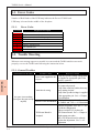
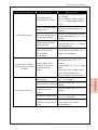
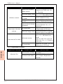
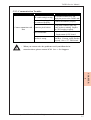
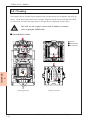
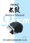
TAIKO Service Manual 5 Chapter Trouble Shooting / Maintenance 5-1. 5-2. 5-3. 5-4. 5-5. 5-6. Error Codes Trouble Shooting Test Mode (Diagnostics) Cleaning Maintenance Tool List Product Support Issue: 11/2006 TAIKO Servic e Manual 5-1. Error Codes Number of Red flashes of the LED lamp indicates the Error of TAIKO unit. LED lamp is located in the middle of the faceplate. 5-1-1. Error Codes # of Flashes 2 3 4 5 6 8 9 12 Diagnostic Description ROM error Banknote remains inside ejection slot Banknote remains inside transport path EEPROM read/write error Motor error Entrance solenoid error Exit solenoid error Fraud detected 5-2. Trouble Shooting When an error message appears or trouble is occures and the TAIKO unit does not work properly, recover the TAIKO unit following the instruction below. 5-2-1. General Troubles Recovery Action Verify the specified voltage and ground Power is not supplied to the are supplied to appropriate pins of the acceptor. interface connector. Verify if all harnesses and connectors are connected properly. Verify if the connector pin has been any Connection is wrong. bend, missing, broken. Verify if the specified voltage is supplied to the appropriate pin. See=> Chapter Acceptor is not working 2 Specifications (Acceptor does not accept Download the appropriate software to any bill) Software is not downloaded. the TAIKO unit. See=> 4-1.Download Perform Acceptance Test. See => 4-2. Test Mode (Diagnostics) If the test result is NG, replace the CPU/Sensor Board is CPU/Sensor Board. See=> Chapter 6 Corrupted. Replacement procedure After CPU/Sensor board is replaced, perform the adjustment. See=> 4-2. Adjustment CHAPTER 5 Symptom/Error Message Possible Causes © 2006 Japan Cash Machine Co.Ltd. All rights reserved. 5-2 TAIKO Service Manual Symptom/Error Message Possible Causes CHAPTER 5 Recovery Action Clean the feed or Pinch roller. See=> 6-4. Cleaning Feed or Pinch roller is If any corruption is found, replace it. spoiled with dirt or broken. See=> 6-2. Replacement of Sensor Board Verify the condition of the Feed or Feed or Pinch roller spring is Pinch roller spring and replace it as missing or loose. required. Remove the foreign objects from the JAM bill occurs often. There is any foreign objects transport path and clean. See=> 5-4. is on the transport path. Cleaning Change the faceplate guide depending Faceplate does not match on the bill width. See=> 3-3. Replace with the bill width. of Faceplate Guide The bill width is 83mm or Use the only acceptable bills. See=> larger or 62mm or less. Chapter 2 Specifications (Out of TAIKO Specifications) Remove the foreign object and clean the entrance sensor. See=> 5-4. Cleaning Entrance Sensor is not Acceptor is not working. Perform Aging. See=> 5-2-6. Aging working or there is any (Acceptor does not accept details foreign object at the any bills.) If any sensor error is found, replace entrance. the CPU/Sensor board. See=> Chapter 6 Replacement Procedure Rollers, belts and lenses is Clean the rollers, belts and lenses. soiled with dirt. See=> 5-4. Cleaning Adjust the TAIKO unit. See=> 5-4. Sensor needs to be adjusted. Cleaning After disassembled, the Adjust the TAIKO unit. See=> 5-4. TAIKO has not been Acceptance rate is low. Cleaning adjusted. Download the latest software program. The software revision is old. See=> 4-1. Download Verify if the denomination, issued year The bill that software program is not supported is is appropriate in the software information sheet. inserted. © 2006 Japan Cash Machine Co.Ltd. All rights reserved. 5-3 TAIKO Servic e Manual Symptom/Error Message Possible Causes Recovery Action Download the appropriate software Software does not match program to the TAIKO unit. See=> with the currency. 4-1. Download Set the accepting setting properly. DIP Switch setting is wrong. See=> 2-7-3. Denomination Setting The command from Host is All bills are returned. Set the command to accept. set to inhibit. CPU/Sensor failure is Replace CPU/Sensor Board. See=> occurred. Chapter 6 Replacement Procedure. Clean all sensors. See=> Cleaning Sensor needs to be cleaned Perform adjustment See=>4-2. and adjusted. Adjustment Replace the CPU board. See=> 6CPU board failure Motor rotates a few times 1. Replacement of CPU board and stop. Set the DIP Switch No.1 ON and DIP Switch setting is wrong. supply the power to the TAIKO unit. Perform the DIP Switch TEST. See=> 5-3-3. DIP Switch Test Details DIP Switch is broken. If the test result is NG, replace the Cannot enter the Test Mode. CPU board. See=> 6-1. Replace of CPU board Replace the CPU board. See=>6-1. CPU board failure Replacement of CPU board 5-2-2. Adjustment Troubles CHAPTER 5 Symptom/Error Message Possible Causes Reference paper is wrong. Adjustment Error CPU/Sensor board failure. Recovery Action Use the reference paper (KS-070) for TAIKO. Replace the CPU/Sensor board. See=> Chapter 6 Replacement Procedure © 2006 Japan Cash Machine Co.Ltd. All rights reserved. 5-4 TAIKO Service Manual 5-2-3. Communication Troubles Symptom/Error Message Possible Causes Recovery Action Set all DIP Switches OFF and DIP switch setting is wrong. supply the power to the TAIKO unit. Connector is unplugged or is Connect all connector properly. not connected properly. Verify if the connector pin is any Cannot communicate with Connector pin is broken. bend, broken or missing. Replace Host the CPU board as required. Replace the CPU board. See=> 6CPU board failure 1. Replacement of CPU board Verify if the interface is appropriate Interface is wrong. with Host. If wrong, set the interface properly. See=> 2-7. DIP Switch - When you cannot solve the problem even if you follow the instruction above, please contact JCM. See => 5-6. Support CHAPTER 5 © 2006 Japan Cash Machine Co.Ltd. All rights reserved. 5-5 TAIKO Servic e Manual 5-3. Test Mode (Diagnostics) TAIKO has the diagnostics function. TAIKO can be specified the part of the error using the diagnostic funktion. 5-3-1. DIP Switch Setting List Test Items SW1 SW2 ON ON DIP Switch Test Transport Motor Forward Rotation Test ON OFF Transport Motor Reverse Rotation Test ON ON ON OFF Sensor Test ON ON Solenoide Test ON OFF Accepting Test ON OFF Entrance Flapper Test ON ON Exit Flapper Test SW3 ON OFF OFF ON ON OFF OFF OFF SW4 ON OFF OFF OFF ON OFF ON ON SW5 ON OFF OFF OFF OFF ON ON ON SW6 ON OFF OFF OFF OFF OFF OFF OFF SW7 ON OFF OFF OFF OFF OFF OFF OFF SW8 ON OFF OFF OFF OFF OFF OFF OFF 5-3-2. DIP Switch Test Procedure Test the DIP switches. 1. Set all DIP switches ON and then supply the power to the TAIKO uit. 2. Set the switch No.1 OFF to start the test. Set the switch Nos.3, 5 and 7 OFF and verify if the LED lamp lights Green. 3. Then set the switch Nos.2, 4, 6 and 8 OFF and verify the LED lamp lights Blue. - IIf TAIKO’s red LED lights, the DIP Switch has a problem. CHAPTER 5 5-3-3. Transport Motor Forward Rotation Test Procedure Test the condition of the Transport Motor forward rotation. 1. Set the switch No.1 ON and supply the power to the TAIKO unit. 2. Set the switch No.1 OFF to start the test. The transport motor rotates forward. 3. If the Blue LED lamp blinks despite the number, the test is completed. No error is found. - If TAIKO’s red LED lamp lights, the Transport Motor has a problem. © 2006 Japan Cash Machine Co.Ltd. All rights reserved. 5-6 TAIKO Service Manual 5-3-4. Transport Motor Reverse Rotation Test Procedure Test the condition of the Transport Motor reverse rotation. 1. Set the switch No.1 and 2 ON and supply the power to the TAIKO unit. 2. Set the switch No.1 OFF to start the test. Ther transport motor rotates reverse. 3. If the Blue LED lamp blinks despite the number, the test is completed. No error is found. - If TAIKO’s red LED lamp lights, the Transport Motor has a problem. 5-3-5. Aging Procedure 1. Set the switch Nos.1, 2 and 4 ON and supply the power to the TAIKO unit. Set the switch No. 1 OFF to start the test. 2. TAIKO unit repeates the following operation. LED lamp lights => Motor rotates foward => Motor rotates reverse 3. If an sensor error is found while aging, the TAIKO stop the operation. You can specified the error of the sensor with the number of the LED lamp blinks. Sensor Position Enterance Sensor Right Enterance Sensor Left Upper Transit Sensor Lower Transit Sensor Enterance Solenoid Sensor Exit Solenoid Sensor VEND Lever Sensor Encoder Sensor Penetration (Upper to Lower) Right IR Penetration (Upper to Lower) Left IR Penetration (Upper to Lower) Right RED Penetration (Upper to Lower) Left RED Penetration (Upper to Lower) Right NIR Penetration (Upper to Lower) Left NIR Penetration (Upper to Lower) Right BLUE Penetration (Upper to Lower) Left BLUE Penetration (Lower to Upper) Right IR Penetration (Lower to Upper) Left IR Penetration (Lower to Upper) Right RED Penetration (Lower to Upper) Left RED Penetration (Lower to Upper) Right NIR Penetration (Lower to Upper) Left NIR Penetration (Lower to Upper) Right BLUE Penetration (Lower to Upper) Left BLUE CHAPTER 5 # of Flashes 1 2 3 4 5 6 7 8 1 2 3 4 5 6 7 8 1 2 3 4 5 6 7 8 © 2006 Japan Cash Machine Co.Ltd. All rights reserved. 5-7 TAIKO Servic e Manual 5-3-6. Solenoid Test Procedure Test the condition of the solenoids. 1. Set the switch Nos.1, 2, 3 and 4 ON and turn ON the power to the TAIKO unit. 2. Set the switch No.1 OFF to start the test. Then the TAIKO unit repeates the following operation. Entrance Flapper On/Off => Exit Flapper On/OFF 3. If the Blue LED lamp lights, no error is found. - If TAIKO’s red LED lights, the Solenoid has a problem. 5-3-7. Accepting Test Procedure Test the condition of the acceptance of the bils. 1. Set the switch No.1 and 5 ON and supply the power ON. 2. Set the switch No.1 OFF to start the test. Then insert the bill to the TAIKO unit. 3. If the bill is returned, the LED flashes depending on the reason for the reterning. CHAPTER 5 # of Flashes 2 3 4 5 6 8 9 12 1 4 5 7 8 9 13 14 15 Diagnostic Description ROM Error JAM inside Acceptor Bill remains inside transport path Adjustment Error Motor Error Entrance Solenoid Error Exit Solenoid Error Sensor operation at the abnormal timing Reject by slant insertion X-rate Error Bill Transportation Error Pattern Error Photo Level Error Reject by Inhibit Setting Bill Length Error Ir/Red Error Reject by counterfeiting currency © 2006 Japan Cash Machine Co.Ltd. All rights reserved. 5-8 TAIKO Service Manual 5-3-8. Entrance Flapper Test Procedure Test the entrance flapper. 1. Set the switch Nos.1, 4 and 5 ON and turn the power to the TAIKO unit. 2. Set the switch No.1 OFF to start the test. Then the entrance flapper repeates open/ close operation. 3. If the Blue LED lamp lights, no error is found. - If TAIKO’s red LED lamp lights, the Entrance Flapper has a problem. 5-3-9. Exit Flapper Test Procedure Test the exit flapper. 1. Set the switch Nos.1, 2, 4 and 5 ON and turn ON the power to the TAIKO unit. 2. Set the switch No.1 OFF to start the test. Then the exit flapper repeates open/close operation. 3. If the Blue LED lamp lights, no error is found. - If TAIKO’s red LED lamp lights, the Exit Flapper has a problem. CHAPTER 5 © 2006 Japan Cash Machine Co.Ltd. All rights reserved. 5-9 TAIKO Servic e Manual 5-4. Cleaning If the paper dust or foreign object spotted in the acceptor parts, the acceptance rate may go down. Clean the acceptor parts once a month. Wipe out on the sensor with lint-free cloth or cotton bud. Remove the paper dust or foreign object completely on the rollers. - DO NOT use the organic solvent such as thinner or benzin, when wiping the TAIKO unit. Sensor/Roller Location CHAPTER 5 Sensor Pinch Roller Feed Roller Open Upper Lid Open Lower Lid © 2006 Japan Cash Machine Co.Ltd. All rights reserved. 5-10 TAIKO Service Manual 5-5. Maintenance Tool List When maintenace or adjust TAIKO unit, the following parts need to be parchased. Items EDP# Part# Power Supply Unit 116125 VM-30 TAIKO Harness A 127527 3280-05-54 TAIKO Harness B 116488 3280-03-11 Clone Harness 124528 3280-05-52 Reference Paper 119581 KS-070 Description This unit is to supply the power to TAIKO unit. This harness is to connect with TAIKO unit ant Power Supply Unit. This harness is to connect with PC and TAIKO unit when downloding or connecting with palm. This harness is to connect with a master TAIKO and a slave TAIKO when cloning. This is a reference paper to adjust TAIKO unit. CHAPTER 5 © 2006 Japan Cash Machine Co.Ltd. All rights reserved. 5-11 TAIKO Servic e Manual 5-6. Product Support If you happen to experience any problems or errors with your TAIKO unit, or have any inquiries regarding your unit, consult with your nearest JCM contact as shown below. Please be sure to make a note of the problem points andy symptoms, or the content of your inquiry, prior to making contact. Japan Japan Cash Machine Co. Ltd. (Headquarters) 3-15, Nishiwaki 2-Chome, Hirano-ku, Osaka 547-0035 Japan Phone: +81-66-703-8406 Fax: +81-66-704-7843 URL: www.jcm-hq.co.jp Americas, Oceania JCM American Corporation 925 Pilot Road, Las Vegas, NV 89119 U.S.A. Phone: +1-702-651-0000 Fax: +1-702-644-5512 e-mail: [email protected] URL: www.jcmamerican.com CHAPTER 5 Europe, Russia, Middle East, Africa Japan Cash Machine Germany GmbH Mündelheimer Weg 60 D-40472 Düsseldorf Germany Phone: +49-211-530645-60 Fax: +49-211-530645-85 e-mail: [email protected] URL: www.jcm-germany.com UK, Ireland JCM United Kingdom Ltd. Unit B, Third Avenue, Denbigh West Business Park Bletchley, Milton Keynes, Buckinghamshire MK1 1EJ, UK Phone: +44-870-770-2863 Fax: +44-190-837-7834 e-mail: [email protected] URL: www.jcm-uk.com Asia (other than Japan) JCM Gold (HK) Ltd. Unit 1-7, 3F., Favor Industrial Centre 2-6 Kin Hong Street, Kwai Chung, N.T. Hong Kong Phone: +852-2429-7187 Fax: +852-2929-7003 e-mail: [email protected] URL: www.jcmgold.com.hk © 2006 Japan Cash Machine Co.Ltd. All rights reserved. 5-12