1
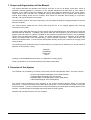
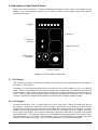
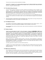
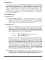
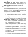
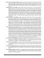
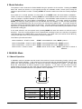
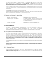
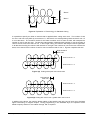
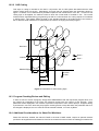
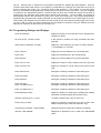
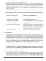
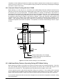
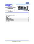
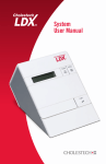
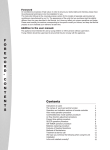
Cox & Wright Ltd.
LC30, LC30S and LC30AS Mk. II Auto Press
Operation & Servicing
July 1992
(Reflects Software Version 3.01)
Prepared by:
Colin H. C. Machin
Mandator Control Systems Limited
31 Dalkeith Road
Sutton Coldfield
West Midlands
B73 6PW
UK.
for:
Cox & Wright Limited
PO Box 27
Sanders Lodge Industrial Estate
Rushden,
Northamptonshire
NN10 9BD
UK.
© 1987, 1988, 1992 - Cox & Wright Ltd.
1 Scope and Organisation of this Manual
This manual describes the operation and first-line servicing of the Cox & Wright LC-30 Mk II series of
Automatic Presses primarily by reference to the operator dialogues that take place at each stage of
operation of the machine and the messages that occur when faults are detected by the control system.
Three models of the LC30 Mk II are considered, namely the standard LC30, the LC30S, which features a
manual sheet loading facility and the LC30AS, which allows for automatic sheet loading in conjunction,
normally, with a pick and place feed system.
The first section gives an overview of the structure of the system showing the interplay between the various
electronic modules.
The second section deals with the control panel and the use of the keypad together with servicing
information on the panel.
The third section deals with switching on the machine and the messages that are encountered in normal and
abnormal start-up situations. In addition, this section deals with the emergency and other failure conditions
together with brief notes on operator remedies for the problems reported where these are not immediately
obvious from the displayed message. Further, this sections attempts to give an indication of the possible
causes of problems that cannot be dealt with by normal operator intervention. Within this section, any
instructions labelled with a '+' must be read and followed carefully as they are critical to the integrity of the
cutting medium.
The remaining sections describe machine mode selection in general and in detail the four normal modes of
operation of the machine, namely
MANUAL
PROGRAM
KNIFE SET
AUTO
including in the PROGRAM mode section a consideration of cutting styles.
Finally, the operation of the machine Maintenance Mode is discussed.
2 Overview of the System
The LC30 Mk II is controlled by a number of units each with their own particular tasks. The main units are:
•
•
•
•
Z-80 microprocessor based Main Control PCB (Colmac)
Programmable Controller (PLC) sub-system
Mandator DMC-124 Digital Motion Control PCB (DMC)
C&W Depth/Daylight Control PCB (DDC)
The Colmac board handles the main operation of the system including operator dialog and machine
sequencing. It passes commands to the DMC board, which then in turn looks after the motion of the head
and feed systems. The PLC provides some of the press interfacing and looks after the safety aspects of the
machine. The C&W Depth and Daylight board looks after the cutting stroke.
Separate manuals describe each unit of the system.
Cox & Wright LC30, LC30S and LC30AS Mk II Operation and Servicing
©1987, 1988, 1992 Cox & Wright, Ltd.
1
3 Description of the Control Panel
Figure 1 shows the control panel. It may be considered as having six zones, namely (1) the display, (2) the
keypad, (3) the knife setting controls, (4) the manual controls, (5) the safety controls and (6) the
maintenance mode key.
COX & WRIGHT
1. Display
2. Keypad
3. Knife Set
Controls
4. Manual Controls
6. Maintenance
Mode Key
5. Safety Controls
Figure 1 LC-30 Mk II Main Control Panel
3.1 The Display
This is where the operator is informed of the status of the machine and is invited to provide information to
the machine control system.
The display is a self-contained module that is connected to the Colmac system via part of a Z-80 PIO
(IC25). There are eight data lines, a strobe line (output from Colmac) and a busy/ready status line back
from the display. If the system is observed to be working but no display is present, check the display for a
cursor. If this is present, assume that the display is functioning and replace the Z-80 PIO at IC25. If there is
no cursor, check the +5V supply to the display and if this is present, change the display module.
3.2 The Keypad
The keypad consists of a set of numeric keys and a set of control keys. Within the numeric set are two
special keys. The Clear key causes the number currently on the display during number entry to be cleared.
The Enter key causes the number currently on the display during number entry to be accepted. In certain
situations during programming and when running the machine in automatic mode, the machine will ask for
some number to be entered. The machine will attempt to guess the number that is most likely to be entered
and will display this. The displayed number may be accepted by simply pressing Enter, thus making certain
parts of the dialog very fast indeed. If the displayed number is not that required, the operator may simply
"overwrite" that number by entering a new one. In this case there is no need to first press Clear.
Cox & Wright LC30, LC30S and LC30AS Mk II Operation and Servicing
©1987, 1988, 1992 Cox & Wright, Ltd.
2
The use of the control keys will be described as necessary.
The keypad is interfaced to the Colmac system through part of a Z-80 PIO (IC26) and is scanned by
software. If no response can be obtained from the keypad, check its connections and if these are seen to
be correct, change the Z-80 PIO at IC26.
3.3 The Knife Setting Controls
The use of these controls is described in the section dealing with the KNIFE SET mode of operation of the
machine. The KNIFE SET procedure sets the position of the machine's depth sensor and the backup
physical depth stop. In normal cutting, the sensor detects the completion of a downstroke and takes the
appropriate action (normally initiating an upstroke). In the event of a failure of this sub-system, the physical
stop prevents damage to the cutting medium by limiting the downward travel of the tool.
Once KNIFE SET mode has been selected and the Colmac board has set the LOW PRESSURE signal, the
remainder of the operation of this feature is taken over by the C&W Depth and Daylight board (see separate
manual).
As this sub-system is responsible for preventing damage to the cutting medium, servicing of this part of the
machine must be referred to Cox & Wright or a competent agent.
3.4 The Manual Controls
The operation of the machine in MANUAL mode is achieved through the use of these controls. This is
described fully in the section dealing with the MANUAL mode of operation of the machine.
The manual traverse and feed controls and the clamp controls are interfaced to the Colmac board as part
of the keypad.
3.5 Safety Controls
There are two buttons within this section of the control panel. Pressing the EMERGENCY STOP button
causes all machine operation to cease. The machine responds by displaying EMERGENCY STOP: Check
Cause and Rectify. Once the problem has been dealt with, the EMERGENCY STOP button, which will have
locked down, may be released by rotating it in a clockwise direction. The machine will respond with
RESTART - Select MODE. The machine is then in the same state as it was at start-up. If, however, the
machine was cutting in AUTO mode, it will be possible to restart cutting at the last complete row by simply
entering AUTO mode in the usual manner, accepting the displayed die reference and number of cuts (see
section dealing with AUTO mode).
Before commencing any operations requiring motion of the head or feed mechanisms or performing a
downstroke, the machine must be in a ready state. If this is not the case, the machine will ask the operator
to Press RESET to Continue. The machine will not be in the ready state after switch-on or if the
EMERGENCY STOP button has been pressed.
The safety signals are interfaced to the Colmac board via the PLC.
In addition to the controls mentioned above, the Colmac system has a Watchdog that will trip the Colmac
system and drop out the safety interlock if the software should fail to "bop" the watchdog within the
prescribed intervals.
3.6 Maintenance Mode Key
This is located at the Auxiliary Function are of the control panel and is used to select the machine start-up
mode. With the key in the extreme anti-clockwise direction, the machine operates normally. The key
should be removed in this position. With the key in its extreme clockwise direction, Maintenance Mode is
selected. This mode is described in the section dealing with Maintenance Mode.
Cox & Wright LC30, LC30S and LC30AS Mk II Operation and Servicing
©1987, 1988, 1992 Cox & Wright, Ltd.
3
4 Switching On
Turn on the machine using the main switch situated on the left-hand side door. The pump will start and
after a short delay one of the start-up messages (see below) will be displayed. If this does not occur,
examine the display. If there is a flashing cursor in the bottom left hand part of the display, then it can be
assumed that the +5V power supply is active. If the cursor does not show, proceed to check out the power
supply. Unless a major failure has occurred, the operator will be invited to Select MODE under normal
operation. If Maintenance Mode has been selected by means of the Maintenance Mode switch, a different
message will appear. This is dealt with in the section on Maintenance Mode. The section on mode
selection describes how to proceed from here, but it is recommended that the reader should gain familiarity
with the failure and hold-up messages that may occur by reading the section that follows rather than
skipping directly to mode selection.
5 Start-up Messages
5.1 Normal Start-up
Cox & Wright LC30-2 Auto - Select MODE - This is the normal start-up message which is to be expected
if all is well. Press MODE to cycle through the allowable modes. Note that the "-2" indicates a 2axis machine. If the display indicates "-3", check the axes select link in the option jumper area of
the Colmac board. "S" will follow the axes indicator if the manual sheet feed option has been
selected or "AS" will follow if the automatic sheet feed option has been selected.
5.2 Abnormal Start-up
n data items lost - Select MODE - Some of the cutting sequence data stored in the battery-backed
memory on the Colmac board has been corrupted. The number of suspect sequences is shown in
this message. Re-entry of missing programs will be required. This is due to either a failure of the
battery (or its associated circuitry) that holds the memory or due to a failure in the control system
that has caused the software to execute program that has overwritten the memory in some way.
First try re-programming a few tools. Due to the way in which data is stored and duplicated, the
approximate distribution of program data to RAM chips is as follows:
main copy:
backup copy:
IC15
IC16
IC17
IC18
die references 1 - 360
die references 361 - 700 (nominal maximum)
die references 1 - 360
die references 361 - 700
Now switch off for a few minutes. Upon switch-on, look for the normal start-up message. If this
appears, assume all is well. If the data lost message occurs again, check the state of the battery
with the power turned off again. The nominal voltage of the battery is 3.6V although this can rise to
something over 4V when it has just come off charge. A voltage lower than 3.6V or a higher voltage
that is seen to be falling when observed on an accurate meter is a sign of a failed battery. Replace
battery. If the battery appears to be functioning properly, check the voltage on each of the battery
backed RAM chips - ICs15-18, pins 14 (0V) and 28 (+5V) with the power off. The battery voltage
should be present here. If this is not the case, check that the battery back-up links are in place
adjacent to the RAM chips that are to be battery backed. If any are missing, re-install them and
check the voltage on the appropriate chip again. If all looks well at this stage, try re-programming a
few tools and then switch off for a few minutes and try again. If the normal start-up message
appears, then assume all is well. If there are still problems, attempt to isolate an area of die
references that are giving trouble in an attempt to locate a faulty RAM chip. If programs for dies in
IC15 remain whilst those in IC16 cause problems, replace IC16, etc.
SYSTEM ERROR - Contact Cox & Wright - An unexpected internal condition has been detected. This
message occurs when the control system software has detected a fault in the EPROM containing
the software. If a serious fault has developed in the EPROM, it is unlikely that the software will
even manage to get as far as displaying this message. Change the EPROM and try again.
Cox & Wright LC30, LC30S and LC30AS Mk II Operation and Servicing
©1987, 1988, 1992 Cox & Wright, Ltd.
4
6 Emergency Stop
EMERGENCY STOP: Check Cause and Rectify - Displayed after Emergency Stop caused by
Emergency Stop button being pressed or side gates being opened. Upon clearing condition,
machine displays a RESTART message (below). If this condition occurs without any obvious
reason, check the switches and contacts on the side gates, as these will also trip the emergency
stop feature.
RESTART - Select MODE - Appears when the Emergency Stop condition has been cleared.
7 Failures and Hold-ups
This section lists the messages which might appear during operation of the machine in either of the modes
of normal machine operation (MANUAL or AUTO) that involve motion of the head or feed mechanisms or
cutting. When a condition marked as fatal occurs, the machine will suspend all further operations and wait
for the operator to press START. This will release the machine and return it to the Select MODE condition.
The alternative is that the machine continues after fixing. In this case it will wait for the operator to fix the
reported problem and will then continue. References to the DMC are concerned with the motion control
sub-system installed in the machine. The main control system carefully checks communication with and
operation of this sub-system and any failures associated with the DMC are fatal.
Press RESET to Continue - The main safety circuit has been tripped and needs to be reset by pressing
the main RESET button. If the RESET button fails to do this, check the master relay and its
connections followed by its signalling to the Colmac board. First check that the signal is reaching
the connector block. If this is the case, look for the input to be turning on the appropriate indicator
LED. If the LED does not light, replace the opto-isolator serving this input. If the LED does light,
replace the Z-80 PIO serving this input.
Please close front guard - Machine cannot be operated in AUTO mode or allow certain MANUAL mode
operations whilst the front guard is lifted. If this message appears even though the front guard is
closed, check the guard closed switch and its connections followed by its signalling to the Colmac
board. First check that the signal is reaching the connector block. If this is the case, look for the
input to be turning on the appropriate indicator LED. If the LED does not light, replace the optoisolator serving this input. If the LED does light, replace the Z-80 PIO serving this input.
FRONT GUARD VIOLATION - Select MODE - The front guard has been lifted and further operation is
suspended until it is restored. If this message appears even though the front guard is closed, check
the guard closed switch and its connections followed by its signalling to the Colmac board. First
check that the signal is reaching the connector block. If this is the case, look for the input to be
turning on the appropriate indicator LED. If the LED does not light, replace the opto-isolator serving
this input. If the LED does light, replace the Z-80 PIO serving this input.
Downstroke failure: Press START to reset - A downstroke has not occurred when commanded by the
control system or its completion was not detected by the control system (fatal). Check to see if the
downstroke is actually being performed or not. If the buffer does not come down, check the output
from the Colmac board. If it is present (note that the LED for the output is driven separately from
the output itself) and can be seen at the connector block, contact Cox & Wright or a competent
agent for service to the depth/daylight control board. If the output is not present but the LED lights,
change the Darlington driver associated with this output and re-try. If the output is not present and
the LED fails to light, change the Z-80 PIO associated with this output. If the buffer comes down
and returns, check the signalling of the completion of the downstroke from the depth/daylight
controller to the Colmac board. First check that the signal is reaching the connector block. If it is
but the LED does not light, change the associated opto-isolator. If the LED does light, change the
associated Z-80 PIO.
Depth Control Fault - Call Cox & Wright - A fault has been detected by the depth/daylight control system
(fatal). Further operation of the machine is locked out. Since this is a self-contained unit and
further operation may result in damage to the cutting medium, Cox & Wright or a competent agent
must be consulted if this message appears.
Datum failure: Press START to reset - The machine was unable to find the datum point within the timeout time (fatal). Check that traverse motion is taking place in the correct direction and if this is the
case, check the datum switch and its signalling to the Colmac board as detailed for the downstroke
above.
Cox & Wright LC30, LC30S and LC30AS Mk II Operation and Servicing
©1987, 1988, 1992 Cox & Wright, Ltd.
5
DMC Comms. failure: Press START to reset - An internal communications failure has occurred (fatal).
Communication between the Colmac board and the DMC has failed after a number of retries. The
Colmac board sends a command and then checks for a response. The response has not come
back from the DMC within the time-out time. Change the DMC board and retry. If this is
unsuccessful, change IC5 and IC6 on the Colmac board. If this is unsuccessful, change IC4 and
then IC31.
DMC Start failure: Press START to reset - Head or feed motion failure (fatal). The Colmac software has
signalled the DMC to start motion but has not received a signal back from the DMC within the
specified time-out time to say that motion has started. This may be caused by a failure in the drive
amplifier or motor or in the analog circuits feeding the amplifier. Retry the operation observing the
analog signal (test point MC on the DMC board) and check that its level changes. This indicates
that the DMC is outputting the analog signal to the amplifier. If the analog signal is not present,
change the DMC board and retry. If this is unsuccessful, change IC5 and IC6 on the Colmac board.
If this is unsuccessful, change IC4 and then IC31. If the analog signal is present, check that the
analog signal is reaching the amplifier and that the amplifier is powered via the appropriate
contactors and/or relays. If all these conditions hold and motion still does not take place, change
the amplifier.
DMC Drive failure: Press START to reset - Head or feed motion failure (fatal). The DMC has been
commanded to start motion and has signalled that it has done so. The Colmac software is
expecting a signal back from the DMC to say that motion is complete but this has not occurred
within the specified time-out time. This may be caused by a failure in the drive amplifier or motor or
in the analog circuits feeding the amplifier. Retry the operation observing the analog signal (test
point MC on the DMC board) and check that its level changes. This indicates that the DMC is
outputting the analog signal to the amplifier. If the analog signal not is present, change the DMC
board and retry. If this is unsuccessful, change IC5 and IC6 on the Colmac board. If this is
unsuccessful, change IC4 and then IC31. If the analog signal is present, check that the analog
signal is reaching the amplifier and that the amplifier is powered via the appropriate contactors
and/or relays. If all these conditions hold and motion still does not take place, change the amplifier.
Sheet feed failure: Press START to reset - The auto sheet feeder has failed to provide a new sheet of
material within the specified time (fatal). The auto feed system is handled by the PLC sub-system.
Upon detecting the end of a sheet of material (rows per sheet has been counted down to zero), the
Colmac board passes a sheet request signal to the PLC. The PLC then starts an external timer that
the operator has set to allow sufficient time to clear the cut pieces from the final row of the sheet.
At the expiry of this timer, the PLC drops the load position bar and then requests the Colmac board
to feed the LC30 belt, simultaneously feeding the feed system belt. This state of affairs continues
until the PLC either detects material at the load position bar (by means of a microswitch) or a timeout occurs. In either case the motion of both belts is stopped and in the latter case a time-out signal
is passed from the PLC to the Colmac. An unexpected condition here is likely to be caused by
either the failure of the PLC to detect the material at the load bar or by a signalling fault between
the PLC and the Colmac. If a signalling failure is suspected, check the PLC outputs and Colmac
inputs associated with this area in the manner detailed for downstroke and other failures.
Head overtravel - Select MODE - In spite of data checking, the head has traversed too far right or left in
AUTO mode. Check that the datum has not been set too far to the right. If this is not the cause,
this condition is probably due to a failure in the DMC.
If the message appears when the head
mechanism is not on the limit, check the signalling to the DMC board.
Feed overtravel - Select MODE - In spite of data checking, the belt has fed too far forward in AUTO
mode. Probably caused by a failure in the DMC or in the feed encoder or feed encoder switching.
If the message appears when the feed mechanism is not on the limit, check the signalling to the
DMC board.
Fixed Clamps problem - Please fix - The fixed clamps have not opened fully (continues after fixing). If it
can be established that the fixed clamps are operating properly, check that the Colmac is driving
the solenoids and then check the signalling to the Colmac both as detailed for the downstroke
problem.
Moving Clamps problem - Please fix - The moving clamps have not returned to their rest position
(continues after fixing). If it can be established that the moving clamps are operating properly,
check that the Colmac is driving the solenoids and then check the signalling to the Colmac both as
detailed for the downstroke problem.
Cox & Wright LC30, LC30S and LC30AS Mk II Operation and Servicing
©1987, 1988, 1992 Cox & Wright, Ltd.
6
8 Mode Selection
The operator is often instructed to Select MODE during the operation of the machine. Pressing the MODE
button will cause the machine to cycle logically through the available modes, at each point inviting the
operator to press START to select. Pressing START will cause the machine to enter the currently displayed
mode.
From switch-on in normal operation, the first press of the MODE button will cause Mode is MANUAL START to select to be displayed. Pressing START will cause MANUAL mode to be entered. This might be
used, for example, to position material for a cutting run. Once MANUAL mode has been left, the next press
of the MODE button will cause Mode is PROGRAM to be displayed. This mode, entered by pressing
START, will allow the cutting sequence for the selected tool to be entered, if it has not been previously.
Upon leaving PROGRAM mode, the next mode to be offered will be KNIFE SET. This mode causes the
machine to execute an automatic depth set procedure. The knife clearance is operated by a timer, which is
adjusted by the appropriate front panel control. Finally, AUTO mode is offered allowing the operator to start
an automatic cutting job.
If the mode offered is not the required mode, pressing MODE will cause the machine to offer the next in
sequence. Thus if the cutting sequence for the selected die is already known to the machine, the operator
could skip directly to the KNIFE SET or even AUTO mode. In the latter case, the machine will not allow any
cutting to take place until a knife set operation has been completed.
The modes cycle as shown below:
Mode is MANUAL - START to select
START selects MANUAL mode; MODE cycles to ...
Mode is PROGRAM - START to select START selects PROGRAM mode; MODE cycles to ...
Mode is KNIFE SET - START to select START selects KNIFE SET mode; MODE cycles to ...
Mode is AUTO - START to select
START selects AUTO mode;
MODE cycles back to Mode is
MANUAL ...
9 MANUAL Mode
9.1 Manual Operation
In MANUAL mode, the operator has full control of the machine in terms of traversing, feeding, cutting, head
rotation and clamp operation. If the machine is of the type that may be operated manually with the front
guard open, then two-handed operation is required for traverse, downstroke and rotation. The table blow
shows the combinations of buttons required for each operation. In all cases, the two buttons must be
pressed within one second of each other and held pressed until the required operation is complete. Both
buttons must be released before the next operation can be requested.
A
D
B
Operation
C
A
B
C
D
Traverse right
Traverse left
Downstroke
Rotate 180°
Cox & Wright LC30, LC30S and LC30AS Mk II Operation and Servicing
©1987, 1988, 1992 Cox & Wright, Ltd.
7
The material feed mechanism is operated by means of the FWD and REV buttons on the main control
panel. The clamps may be operated by use of the clamp MOVING and FIXED button pairs on the main
control panel as signified by the arrow legends. The clamps will be operated and sequenced as appropriate
during feed operations in order to maintain material integrity.
A knife set operation must have been performed before any manual downstroke is allowed. If the machine
is fitted with a tool change key, no further knife set operation will be required unless the key is removed with
the guard lifted.
Pressing STOP causes the machine to leave manual mode.
The buffer buttons are interfaced to the Colmac board via PIO inputs. The manual feed and clamp control
buttons are interfaced to the Colmac board as part of the keypad matrix.
9.2 Message and Displays in Manual Mode
MANUAL: Press STOP to exit
Displayed upon entry to MANUAL mode
Knife set required - Select MODE
A manual downstroke has been requested and the
machine suspects that the tool has been changed since
the last knife set operation
Aborted - Select MODE
Displayed as exit is made from MANUAL mode
10 PROGRAM Mode
The first part of this section deals with the general aspect of LC30 Mk II programming as applied to all
models in the range. Users of the S and AS models will need to refer to section 10.3 (Additional
Considerations for Sheet Fed Machines LC30S and LC30AS) for instructions peculiar to these models.
10.1 Program Creation and its Terminology
This is where the operator is able to instruct the machine on how to cut for a particular die. Each die is
known to the machine by its Die Reference. Distances for traverse, feed, interlock and other parameters
(see figure 2) are supplied by the operator in the units selected for the machine. The units are selected by a
one of the option links on the Colmac board and are set to the customer's requirements prior to despatch.
These units are either tenths of millimetres (mm/10) or thousands of an inch (thou). For example, in metric
units, a traverse distance of 200mm would be entered as 2000. In imperial units, a traverse distance of 7"
would be entered as 7000.
Pressing STOP during programming will cause an exit from PROGRAM mode without affecting the selected
program.
There are two basic cutting styles, namely standard and CAD. The style for a given Die Reference is
selected as the first step in the programming of a cutting sequence. These two cutting styles are described
separately below.
10.2.1 Standard Cutting
There are notionally two rows of cutting, row 1 and row 2 and the buffer moves to the right whilst cutting row
1 and cuts row 2 as it returns, having fed the material. It then returns to the datum point again and cuts
(another) row 1 and so on (figure 3).
Cox & Wright LC30, LC30S and LC30AS Mk II Operation and Servicing
©1987, 1988, 1992 Cox & Wright, Ltd.
8
Feed
Direction of Feed
Datum Point
Interlock
"Row 2"
"Row 1"
Traverse
Figure 2 Explanation of Terminology for Standard Cutting
It is possible to specify an offset or interlock that is applied before cutting each row 2. The number of cuts
for row 1 and row 2 may differ by a maximum of 1, with that for row 2 always being less than that for row 1 if
it is not the same. The machine checks for this latter condition and if it does not hold, will transpose the
number of cuts for the two rows. The precise cutting pattern is determined by whether or not the number of
cuts for the two rows is the same or not. In left to right cutting, the machine will always interlock rightwards.
In bi-directional cutting the machine will interlock to the right if the numbers of cuts for the two rows are the
same, but to the left if the number of cuts for row 2 is less than that for row 1. Figures 3 explains this also.
Right interlock
after row 1
Cuts in row 2 = 5
Cuts in row 1 = 5
Figure 3(a) Cutting with equal cuts in both rows
Left interlock
after row 1
Cuts in row 2 = 4
Cuts in row 1 = 5
Figure 3(b) Cutting with cuts in row 1 greater than cuts in row 2
In addition to the above, the machine allows rotation of the head by 180° at the end of each row to facil itate
tighter interlocking of irregular shapes. During programming in the Standard Style, the operator will be
asked to specify whether or not rotation through 180° is required.
Cox & Wright LC30, LC30S and LC30AS Mk II Operation and Servicing
©1987, 1988, 1992 Cox & Wright, Ltd.
9
10.2.2 CAD Cutting
This style of cutting is intended to be used in conjunction with a CAD system that determines the best
regular cutting layout for the die. Alternatively, this style may be selected when the dimensions shown in
figure 4, overleaf, can be determined by detailed inspection and measurement of the die. In order for this
cutting style to be applied, the machine needs to know the normal width of material in use. The normal
material will be requested during programming but will be confirmed when the cutting sequence is selected
in AUTO mode. This feature allows the width of the standard material to be made known to the machine,
but for different width material to be used without the need for changing the stored program.
Row feed
Centre of
rotation
Row 2
Interfeed
Row 1
Material Edges
x
y
Direction
of feed
Row offset
Intertraverse
Traverse
Figure 4 Parameters for CAD Cutting Style
10.3 Program Checking/Review and Editing
In order to check or review a program, simply select PROGRAM mode and request the program which is to
be checked by responding to the Enter die reference prompt with the number of that program. Each
parameter will be displayed in turn if Enter is pressed in response to each further prompt. Program editing
is performed in much the same way as program checking/review except that when the parameter that is to
be changed is displayed, the new value should be entered followed, of course, by Enter.
10.4 Additional Considerations for Sheet Fed Machines
Sheet fed machines, whether the manual LC30S or the auto LC30AS model, require an optional material
pre-feed to be supplied that will determine how far the material is to be fed from the loading point before the
Cox & Wright LC30, LC30S and LC30AS Mk II Operation and Servicing
©1987, 1988, 1992 Cox & Wright, Ltd.
10
first cut. Entering zero in response to this question will defeat the material pre-feed operation. With the
LC30S manual sheet feed machine, the operator is responsible for informing the LC30 when the end of a
sheet is reached (see section 12.1 concerning AUTO mode operation). The LC30AS, on the other hand,
has to be informed during programming of how many rows may be cut from each sheet. This item, supplied
in response to the appropriate question, controls the point at which the LC30AS will request a new sheet of
material from the automatic sheet loader during AUTO mode operation. On the LC30AS, the material is
automatically fed from the load point to a point in the centre of the cutting tool. Thus the pre-feed distance
supplied during programming is usually specified as just greater than half the front to back depth of the tool.
This will bring the material to a point where the first row will be cut just inside the leading edge of the sheet.
For the LC30S, the user will need to determine the feed distance required to bring the material from the
load point to a position at which the first row will be cut.
10.5 Programming Dialogue and Displays
Enter die reference
Supply the reference of the die that is to be programmed,
reviewed or edited
No such die ref. - Please re-enter
A die reference outside the range permitted has been
specified
Select style [1=Standard; 2=CAD]:
Supply the code relating to the style of cutting required '1' for standard or '2' for CAD
Enter Traverse:
Supply the traverse distance in the units specified
Enter Feed:
Supply the feed distance in the units specified
Enter Interlock:
Supply the interlock distance in the units specified
Enter Cuts 1st. row:
Supply the number of cuts to make in the first of two rows
Enter Cuts 2nd. row:
Supply the number of cuts to make in the second of two
rows
Enter Intertraverse:
See figure 4 relating to details of CAD cutting style
Enter Row offset:
See figure 4 relating to details of CAD cutting style
Enter Interfeed:
See figure 4 relating to details of CAD cutting style
Enter Row feed:
Enter Tool Dimension X
See figure 4 relating to details of CAD cutting style
See figure 4 relating to details of CAD cutting style
Enter Tool Dimension Y
See figure 4 relating to details of CAD cutting style
Enter Material pre-feed
Supply the distance to feed (zero to defeat) after loading
new sheet of material (sheet fed machines only)
Rotation required (0=no; 1=yes)?
Is rotation required at the end of each row?
Enter Rows per sheet
Supply the number of rows that are to be cut from each
sheet of material (auto sheet fed machines only)
Programming complete - Select MODE
All data has been accepted and verified successfully
Aborted - Select MODE
Displayed as premature exit is made from PROGRAM
mode
Cox & Wright LC30, LC30S and LC30AS Mk II Operation and Servicing
©1987, 1988, 1992 Cox & Wright, Ltd.
11
10.6 Programming Errors
The data provided by the operator during programming is checked, as far as is possible, for consistency.
Any inconsistencies detected are reported to the operator who is then invited to Select MODE. It is
recommended that the program in question is checked/reviewed and corrected before proceeding. The
program is again checked before being used in AUTO mode.
None of these errors have any implications as far as servicing is concerned.
Single traverse too large - Select MODE
A traverse distance was specified exceeding the
maximum allowed.
Total traverse too large - Select MODE
The total traverse (plus interlock if specified and
rightwards) exceeds the operating width of the machine.
Interlock exceeds traverse - Select MODE
The interlock is not allowed to exceed the traverse
distance (it is typically half the traverse distance).
Int'trav exceeds traverse - Select MODE
The intertraverse is not allowed to exceed the traverse
distance (see figure 4).
Row o'set exceeds traverse - Select MODE
The row offset is not allowed to exceed the traverse
distance (see figure 4).
Zero traverse not allowed - Select MODE
A zero traverse was specified and this is not allowed.
Feed distance too large - Select MODE
A feed distance was specified that exceeds the moving
clamp range.
Zero feed not allowed - Select MODE
A zero feed was specified and this is not allowed.
Zero cuts not allowed - Select MODE
Zero was specified for the number of cuts in at least one
of the rows and this is not allowed.
Cuts per row inconsistent - Select MODE
The number of cuts specified for rows 1 and 2 differ by
more than 1.
Too many rows per sheet - Select MODE
The maximum number of rows per sheet that can be
specified is 255 (auto sheet fed machines only).
11 KNIFE SET Mode
This mode is used to set the depth of cut that is to be used during MANUAL or AUTO cutting. The
procedure is totally automatic and is controlled by the depth/daylight controller PCB. The CLEARANCE
control may be used to set the die clearance after cut. Turning the control in a clockwise direction increases
the clearance. The effect of any changes to this control will not be seen until the next downstroke is
performed.
If extra depth is required, this can be added in small quantities by turning the knurled wheel on the face of
the buffer. In order to turn this wheel, the brake must be released by pressing the button immediately below
it. Turning the wheel in a clockwise direction increases depth whilst turning it in an anticlockwise direction
reduces depth.
IMPORTANT NOTE: It should be understood that this operation moves the physical depth stop and
that repeated increases in depth may compromise the integrity of the depth control sub-system and
endanger the cutting medium.
Certain materials require extra cutting pressure rather than extra depth. In order to accommodate this, a
dwell on depth feature is included. This instructs the depth control sub-system to hold the buffer at depth for
a short time to allow pressure to build up. The HOLD PRESSURE control is used to achieve this, turning
Cox & Wright LC30, LC30S and LC30AS Mk II Operation and Servicing
©1987, 1988, 1992 Cox & Wright, Ltd.
12
the control in a clockwise direction to increase the pressure.
The machine will require a knife set operation to be performed before any operation that involves a
downstroke - MANUAL or AUTO. The tool change key, if fitted to the machine, must be in place during the
knife set operation. Once a knife set has been performed, any removal of the tool change key with the front
guard in its raised position will cause the machine to require another knife set operation. This prevents the
operator from changing the tool and neglecting to perform a knife set operation for the new tool. If a tool
change key is not fitted, any lifting of the front guard, other than in AUTO hold will cause the machine to
require a new knife set.
Pressing the STOP button will cause the machine to exit KNIFE SET mode, but the knife set operation will
be deemed incomplete.
Once KNIFE SET mode has been selected and the Colmac board has signalled the C&W Depth and
Daylight board, the remainder of the operation of this feature is taken over by that board (see separate
manual).
KNIFE SET: Press STOP to exit
Displayed on entry to KNIFE SET mode
Please replace tool change key
The tool change key must be locked in place during the
knife set operation
Knife set in progress - please wait
An automatic knife set is in progress
Knife set complete - Select MODE
The knife set operation has been successfully completed
Please replace tool change key
The tool change key must be locked in place during the
knife set operation
Depth Control Fault - Call Cox & Wright
A fault has been detected by the depth/daylight control
system. Further operation of the machine is locked out.
Since this is a self-contained unit and further operation
may result in damage to the cutting medium, Cox &
Wright must be consulted if this message appears.
Aborted - Select MODE
Displayed as exit is made from KNIFE SET mode
12 AUTO Mode
In automatic mode, the machine will proceed to cut a whole job using a single, specified cutting pattern.
Once started, the job may be interrupted (held) for attention to material or for some other reason, or it may
be stopped permanently. If the job is held, by pressing the HOLD key, the operator is able to operate the
machine in a semi-manual mode. In this case, the manual feed and clamp controls become active to allow
the material to be changed or repositioned. The job may then be restarted or stopped by following the
instructions on the display. The options available for restarting the machine differ depending upon whether
the machine is a sheet fed machine or a roll fed machine as shown in the explanation of messages below.
If the job is to be stopped whilst the machine is running, the STOP key is pressed. In this case, the machine
will complete the current row and will then feed the material to clear the most recently cut pieces.
In section 10.1 on programming, it was mentioned that all cutting takes place from the datum point. This is
defined by the position of a datum switch above the front guard. To cause the machine to start cutting
further to the left or the right, simply move the switch in the desired direction.
Pressing STOP before the job is actually started will cause the machine to exit AUTO mode and will require
the operator to re-select the required mode. Pressing STOP once the job has started will cause the job to
stop after the current row has been completed as detailed above.
12.1 Manual Sheet Feeding with the LC30S
For a manually fed sheet machine, the material will always feed by the specified pre-feed distance before
cutting commences. In order to allow material changing to take place, the HOLD key should be pressed
when the end of the sheet is reached. The machine will then allow manual feed and clamp operation (the
semi-manual mode detailed above) to facilitate the loading of a new sheet. Pressing the START key at the
Cox & Wright LC30, LC30S and LC30AS Mk II Operation and Servicing
©1987, 1988, 1992 Cox & Wright, Ltd.
13
completion of sheet loading will allow the LC30S to pre-feed the material from the load point to a position in
which the first row may be cut. Thus the operator simply proceeds as instructed by the displayed messages
(as shown in section 12.4 below).
12.2 Automatic Sheet Feeding with the LC30AS
Before starting to cut the first row of a new sheet, the LC30AS always feeds the material forward from the
load bar by an amount that will bring the leading edge of the sheet to the centre line of the cutting head plus
the amount given for the selected die. This latter distance is normally, as discussed in the section on
programming the LC30AS, just greater than half the front to back depth of the tool. The LC30AS then cuts
the number of rows given during programming for the sheet in question - rows per sheet - before requesting
the automatic sheet feeder to supply a new sheet of material. During the automatic feed operation, the
LC30AS monitors the condition of the feeder and keeps the operator informed through messages on the
display. If the automatic sheet feeder fails to deliver a new sheet within a pre-specified and fixed time, it
will abort the operation and inform the operator. The operation of automatic sheet feeding is shown in figure
5 below.
Head and Tool
Load
Position Bar
Head
Tool
Load
Position Bar
Fixed pre-feed (set by Cox & Wright)
Pre-feed determined by tool dimensions
and set by operator
Figure 5 Automatic Sheet Feeding on the LC30AS Mk II
12.3 Additional Safety Features Operating During AUTO Mode Cutting
Before allowing a program to be started, the machine checks the data for the selected program. Thus if an
error was reported during programming but was ignored, the machine will not allow that program to be
selected for an automatic run. Re-programming is required before the program can be used.
The front guard must be in place before automatic cutting can commence. This condition will be enforced
by the machine and the operator will be asked to restore the front guard if it is not in place. If the front
guard is lifted during automatic cutting, the machine will stop and AUTO mode will need to be reselected.
If the machine suspects that the tool has been changed since the last knife set operation, automatic cutting
will not be allowed.
Cox & Wright LC30, LC30S and LC30AS Mk II Operation and Servicing
©1987, 1988, 1992 Cox & Wright, Ltd.
14
12.4 AUTO Mode Dialogue and Displays
Aborted - Select MODE
STOP was pressed before the job was started
Knife set required - Select MODE
Auto mode cannot be entered if the machine suspects
that the tool has been changed since the last knife set
operation
Please close front guard
The machine cannot be operated in AUTO mode whilst
the front guard is lifted
Enter die reference
Supply the reference of the die that is being used
No such die ref. - Please re-enter
A die reference outside the range permitted has been
specified
No Program for Die Ref. - Select MODE
A cutting program has not been supplied for this die
reference
Enter number of cuts for this job:
Specify the number of pieces that are required from this
run
Material width for job:
Specify the with of material actually in use (only when
cutting in CAD style)
AUTO: START to Go or STOP to Abort
Data retrieved, machine is waiting to start run
START to Continue or STOP to Abort
The front guard was lifted and then restored after
entering AUTO mode; machine is waiting to restart
Material pre-feed...
Machine is pre-feeding new sheet of material prior to first
cut (sheet fed machines only)
Awaiting material ...
Machine is waiting for a signal from the auto sheet feeder
indicating that a new sheet is in position (auto sheet fed
machines only)
Squaring sheet and datuming ...
A new sheet of material has been supplied from the auto
sheet feeder and is now being positioned whilst the
cutting head is seeking the datum point (auto sheet fed
machines only)
Re-establishing datum - please wait ...
In the CAD cutting style, no reference is normally made
to datum after the first row has been cut and so the
machine re-checks the datum position periodically
Cuts made: 726 Cuts remaining: 274
A record is kept and displayed of how the job is
progressing
HOLD requested - Please wait
HOLD key was pressed, current operation is being
completed
Job held: START to Go or STOP to Abort
Job in hold, machine is waiting to restart run (roll fed and
auto sheet fed machines only)
HOLD=release; START=new sheet; or STOP
Job in hold, machine is waiting to restart run. HOLD will
restart from the current position, START will pre-feed the
new sheet and then start cutting from the datum point
(manual sheet fed machines only)
Auto hold: START to Go or STOP to Abort
Replaces above message after a problem has been
encountered and fixed
STOP requested - Completing this row ...
STOP key was pressed, machine completes current row
before stopping
Aborted - Select MODE
Displayed as premature exit is made from AUTO mode
Job stopped - Select MODE
Machine exits AUTO mode when row is complete after
STOP
Job complete - Select MODE
Machine exits AUTO mode when job is complete
Cox & Wright LC30, LC30S and LC30AS Mk II Operation and Servicing
©1987, 1988, 1992 Cox & Wright, Ltd.
15
13 MAINTENANCE Mode
Maintenance mode is primarily provided to allow the service engineer to test various machine functions. In
addition, access to the MemPak memory module is provided in this mode. Maintenance mode is selected
in one of two ways, both of which rely upon the Maintenance Mode keyswitch at the Auxiliary Function
position on the front panel. This key must be turned to its fully clockwise extent before Maintenance mode
can be entered. If the machine is switched on with the key in this position, Maintenance mode is entered
directly. If the key is turned whilst the machine is running in normal mode, pressing the MODE button at a
Select MODE prompt will cause Maintenance mode to be entered. The machine will not allow Maintenance
mode to be entered unless the operator can provide the current password (in fact a five digit number). This
is preset to the default "12345" during manufacture but may be changed later.
Maintenance mode offers four options, namely:
MEMORY SAVE
MEMORY LOAD
MACHINE TEST
CHANGE PASSNO.
Mode selection is performed in the same manner as for normal operation. Pressing MODE cycles through
the modes and pressing START selects the currently displayed mode. Each mode is now described.
13.1 MEMORY SAVE
The machine will require that the MemPak is connected and then the START key should be pressed in
accordance with the displayed instruction. The saving process will then start, followed by a verification
process. If the contents of the MemPak is the same as the main memory, the machine will report that the
save operation is complete. If the verification reveals any differences, the save will be retried up to five
times. If the save operation is not completed, the machine will report the fact.
13.2 MEMORY LOAD
During loading, the choice is given to allow the sequences stored in the MemPak to completely overwrite
the sequences stored in the machine or to simply replace only sequences that are known to be faulty within
the machine. These options are described as overwrite and merge respectively. Verification takes place
during the loading operation and any persistent faults are reported. At the end of the load operation, the
machine reports success or failure.
13.3 MACHINE TEST
This is a procedure normally used during initial machine configuration and set-up or when service has been
required. The machine is put through a cyclic series of tests in order to prove all functions of the machine.
The display provides information on the current phase of the test cycle.
13.4 CHANGE PASSNO.
This allows the password (in fact a five digit number) that controls access to Maintenance mode to be
changed for security reasons. The machine requests that the new password be keyed twice so that any
keying errors do not result in a password that is not reproducible. The new password will be accepted only if
the two entries agree.
Cox & Wright LC30, LC30S and LC30AS Mk II Operation and Servicing
©1987, 1988, 1992 Cox & Wright, Ltd.
16
Index
Amplifier, motion control sub-system
AUTO mode
Axes selection
7
14
5
Battery, memory back-up
Bi-directional cutting
5
10
Checking, program
Clamps, fixed, problem
, moving, problem
, operation
C (clear) key
CLEARANCE control
Close clamp switch
Colmac
Colmac/PLC protocol
Control panel
11
7
7
9
3
13
9
1
7
2
Data loss
Datum
, failure
DDC
Depth and daylight board
DEPTH control
Die data distribution, memory
Die Reference
Display
, fault
, start-up
DMC
Drive, motion control sub-system
Downstroke
, buttons
, failure
5
7, 9. 14
7
1
1, 3, 6, 13, 14
13
5
4, 5, 9, 11, 16
3
5
5
1, 7
7
6
8, 9
6
E (enter) key
Editing, program
EMERGENCY STOP button
EMERGENCY STOP procedure
EPROM, program
Errors, programming
2, 11
11
4
4, 6
5
13
Feed
Feed, manual
Feed request
Feed operation
FORWARD button
Front Guard
9, 10, 11
4
4, 7
9
9
6
HOLD key
Hold operation, LC30
, LC30S
, LC30AS
14
14
14
15
Interlock
10
Keypad
KNIFE SET mode
Knife Setting Controls
Knife Setting procedure
2
13
3
13
Cox & Wright LC30, LC30S and LC30AS Mk II Operation and Servicing
©1987, 1988, 1992 Cox & Wright, Ltd.
17
Links, battery back-up
Left to right cutting
LOW PRESSURE signal
5
9
4
Manual Controls
MANUAL mode
Manual feed
Manual traverse
Material pre-feed, automatic sheet loading
, manual sheet loading
MC test point
Memory, battery back-up
, die data distribution
, EPROM
Messages
Aborted - Select MODE
Auto hold: START to Go or STOP to Abort
AUTO: START to Go or STOP to Abort
Awaiting material …
Cuts made: 726 Cuts remaining: 274
Cuts per row inconsistent - Select MODE
Cox & Wright LC30-2 Auto - Select MODE
n data items lost - Select MODE
Datum failure: Press START to reset
Depth Control Fault - Call Cox & Wright
DMC Comms. failure: Press START to reset
DMC Drive failure: Press START to reset
DMC Start failure: Press START to reset
Downstroke failure: Press START to reset
EMERGENCY STOP: Check Cause and Rectify
Enter Cuts 1st. row:
Enter Cuts 2nd. row:
Enter die reference
Enter Feed
Enter Interlock:
Enter Intertraverse
Enter Material pre-feed
Enter number of cuts for this job:
Enter Row Feed
Enter Row Offset
Enter Rows per sheet
Enter Traverse:
Enter Tool Dimension X
Enter Tool Dimension Y
Feed distance too large - Select MODE
Feed overtravel - Select MODE
Feed position error - Select MODE
Fixed Clamps problem - Please fix
FRONT GUARD VIOLATION - Select MODE
Head overtravel - Select MODE
Head position error - Select MODE
HOLD requested - Please wait
HOLD=release; START=new sheet; or STOP
Int'trav exceeds traverse - Select MODE
Interlock exceeds traverse - Select MODE
Job complete - Select MODE
Job held: START to Go or STOP to Abort
Job stopped - Select MODE
KNIFE SET: Press STOP to exit
Knife set in progress - please wait
Knife set required - Select MODE
4, 8, 9
8
4, 9
4, 8
15
14
7
5
5
5
Cox & Wright LC30, LC30S and LC30AS Mk II Operation and Servicing
9, 12, 14, 16
16
16
16
16
13
5
5
7
6, 14
7
7
7
6
4, 6
12
12
11, 12, 16
12
12
12
12
16
12
12
12
12
14
14
13
7
9
7
6
7
9
16
16
13
13
16
16
16
14
14
9, 16
©1987, 1988, 1992 Cox & Wright, Ltd.
18
Knife set complete - Select MODE
MANUAL: Press STOP to exit
Material pre-feed...
Material width for job:
Mode is AUTO - START to select
Mode is MANUAL - START to select
Mode is KNIFE SET - START to select
Mode is PROGRAM - START to select
Moving Clamps problem - Please fix
No Program for Die Ref. - Select MODE
No such die ref. - Please re-enter
PLC Comms. failure: Press START to reset
Please close front guard
Please replace tool change key
Press RESET to Continue
Programming complete - Select MODE
Re-establishing datum - please wait …
RESTART - Select MODE
Rotation required (0=no; 1=yes)?
Row o'set exceeds traverse - Select MODE
Select style [1=Standard; 2=CAD]:
Sheet feed failure: Press START to reset
Single traverse too large - Select MODE
Squaring sheet and datuming …
START to Continue or STOP to Abort
STOP requested - Completing this row ...
SYSTEM ERROR - Contact Cox & Wright
Too many rows per sheet
Total traverse too large - Select MODE
Upstroke failure: Press START to reset
Zero cuts not allowed - Select MODE
Zero feed not allowed - Select MODE
Zero traverse not allowed - Select MODE
mm/10
MODE key
Mode Selection
Modes
AUTO
KNIFE SET
MANUAL
PROGRAM
14
9
16
16
8
8
8
8
7
16
12, 16
7
6, 16
14
4, 6
12
16
4, 6
12
13
12
7
13
16
16
16
5
13
13
7
13
13
13
9
8
8
14
13
8
9
Open clamp switch
Overtravel, feed
, head
9
7
7
PLC
communications
PLC/Colmac protocol
Pre-feed, sheet material, automatic
, manual
Program checking
Program editing
PROGRAM mode
Programming errors
Protocol, PLC/Colmac
1, 7
7
7
11, 12, 15
11, 12, 14
11
11
9
13
7
RAM
RAM, battery back-up
RAM, die data distribution
READY, display
machine
5
5
5
2
4
Cox & Wright LC30, LC30S and LC30AS Mk II Operation and Servicing
©1987, 1988, 1992 Cox & Wright, Ltd.
19
PLC protocol signal
RESET button
REVERSE button
Row organisation
Rows per sheet
7
4, 6
9
10, 11
12, 15
Safety Controls
Sheet Material pre-feed, automatic
, manual
Side gates, Emergency stop
START key
STOP key
4
11, 12, 15
11, 12, 14
6
6, 8
9, 14
thou
Traverse
Traverse buttons
Traverse, manual
9
11
8
3, 4, 8
Units, operation
9
Watchdog
4
Cox & Wright LC30, LC30S and LC30AS Mk II Operation and Servicing
©1987, 1988, 1992 Cox & Wright, Ltd.
20