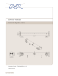
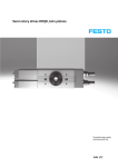
1
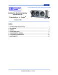
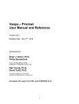
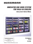
COLMAC COIL When you want Quality, specify COLMAC! Manufacturing Inc. Installation, Operation, and Maintenance ENG00018005 Rev B SPR SPIRAL TOWER COIL Contents 1. SAFETY INSTRUCTIONS .......................................................................................................... 1 2. INSTALLATION .......................................................................................................................... 3 3. PIPING......................................................................................................................................... 4 4. ELECTRICAL .............................................................................................................................. 8 5. GENERAL OPERATION............................................................................................................. 9 6. HOT GAS DEFROST OPERATION............................................................................................ 9 7. WATER DEFROST OPERATION ............................................................................................. 11 8. WATER AND HOT GAS DEFROST OPERATION .................................................................. 13 9. ELECTRIC DEFROST OPERATION ........................................................................................ 13 10. AIR DEFROST OPERATION .................................................................................................. 14 11. MAINTENANCE ...................................................................................................................... 15 12. TROUBLESHOOTING ............................................................................................................ 16 Air Defrost Electric Defrost Hot Gas Defrost Water Defrost Water and Hot Gas Defrost Low Temperature (less than 20°F [-6.7°C] Medium Temperature (+20°F [-6.7°C] and up) High Temperature (+40°F [7.2°C] and up) COLMAC 1. SAFETY INSTRUCTIONS To avoid serious personal injury, accidental death, or major property damage, read and follow all safety instructions in the manual and on the equipment. Maintain all safety labels in good condition. If necessary, replace labels using the provided part numbers. This is the safety alert symbol. It is used to alert you to potential personal injury hazards. Obey all safety messages that follow this symbol to avoid possible injury or death. DANGER indicates a hazardous situation which, if not avoided, will result in death or serious injury. WARNING indicates a hazardous situation which, if not avoided, could result in death or serious injury. CAUTION indicates a hazardous situation which, if not avoided, could result in minor or moderate injury. NOTICE indicates instructions that pertain to safe equipment operation. Failure to follow these instructions could result in equipment damage. PUR00019535 PUR00019560 PUR00019561 1 ENG00018005 Rev B, 10-6-15 COLMAC PUR00019536 PUR00019634 PUR00019628 PUR00019628 2 ENG00018005 Rev B, 10-6-15 COLMAC 2. INSTALLATION 2.1. Inspection 2.1.1. Damage or Shortage – Upon receipt of equipment, inspect for shortages and damage. Any shortage or damage found during initial inspection should be noted on delivery receipt. This action notifies the carrier that you intend to file a claim. Any damaged equipment is the responsibility of the carrier, and should not be returned to Colmac Coil without prior notification. If any shortage or damage is discovered after unpacking the unit, call the deliverer for a concealed damage or shortage inspection. The inspector will need related paperwork, delivery receipt, and any information indicating his liability for the damage. 2.1.2. Specified Equipment – Check unit nameplate for: Electrical specifications to ensure compatibility with electrical power supply. Model Nomenclature and other information to match original order. 2.2. Mounting and Rigging 2.2.1. The unit(s) must be mounted level for proper performance and refrigeration oil return. 2.2.2. Individual towers may be moved with a forklift utilizing the shipping skid. Once uncrated, forklifts can be used to lift units into place with the lifting angle provided at the base of the coil. Lifting angles should be removed upon final installation for hygienic reasons. It may be necessary to cut lifting angle into sections for removal. See Figures 1, 2, and 3 for more information. 2.2.3. Unit may be lifted with hangers, provided a spreader bar is used with proper attachment to the hangers. See Figures 4 and 5 for more information. 2.2.4. NOTICE: Do not place forks or lifting straps in direct contact with drainpan. 2.2.5. CAUTION: Where the finned surface of the coil is exposed, extreme care should be taken to avoid contact with the sharp edges of the fins to minimize the chance of injury. 2.3. Flashing Installation 2.3.1. Due to the large number of freezer configurations, it is not feasible to detail all of the flashing installation details in this installation manual. Each tower coil order, however, includes a copy of custom flashing assembly drawings. Each flashing part is labeled with a letter which corresponds to its actual installation location on the field assembly drawings. If these drawings cannot be located with your unit, please consult factory. 2.4. Defrost Selection 2.4.1. Determination of defrost should be based on several variables. Energy costs, availability of sufficient supply of water or hot gas, system first cost considerations, and last but not least, the refrigerated spaces operating temperature. Air defrost can certainly not be applied in cold storage applications with temperatures below 40°F. Likewise, the use of a hot gas system in a +42°F (5.6°C) room may be overkill. Table 1 shows recommended guidelines for defrost system selection relative to refrigerated room temperature. 3 ENG00018005 Rev B, 10-6-15 COLMAC Table 1 Recommended Room Temperature Ranges for Different Defrost Types Hot Gas Water Water and Hot Electric Defrost Defrost Gas Defrost Defrost YES YES* YES* YES Temperature Range Low Temp (<20°F [-6.7°C]) Air Defrost YES** Medium Temp (<40°F and >20°F [-6.7°C]) YES YES YES YES YES** High Temp (>40°F [7.2°C]) N/A YES YES N/A YES *Not recommended for use on sequential defrost freezers or continuous operation freezers. **Batch processes only. 3. PIPING 3.1. Refrigerant Piping 3.1.1. Ammonia Install all refrigeration and piping components in accordance with the IIAR Ammonia Refrigeration Piping Handbook and other applicable local and national codes. Piping practices for ammonia are also described in the “System Practices for Ammonia Refrigerant” chapter in the ASHRAE Refrigeration Handbook. Coil connections are aluminum flanges supplied with dielectric bushings, gasket, bolts, and mating steel socket weld flanges. For maintaining leak-free joints, be sure to support supply and return piping independent of the coil and re-assemble dielectric flange unions as shown in Figure 8. Always re-check flanges for tightness prior to system startup. Units equipped with bimetallic coupling connections can be welded directly to system piping after removal of the factory welded cap. Remove cap so that at least 4” of the connection stub remains. Do not weld within 4” of the bimetallic coupler (see Figure 9). Note: Evaporators with liquid feed orifices for liquid overfeed must have liquid refrigerant supplied to the coil inlet at a pressure 5 psig (35 kPa) above saturated suction pressure, and at a temperature not exceeding 30°F (-1.1°C) above saturated suction temperature. Please consult factory if conditions exceed the aforementioned recommendations. 3.1.2. Halocarbon Use good practices as described in the “System Practices for Halocarbon Refrigerants” chapter in the ASHRAE Refrigeration Handbook, or other industry publications. Coil connections are copper “sweat” connections. 3.2. Hot Gas Defrost Piping 3.2.1. With this method of defrost, some of the hot discharge gas from the compressor is routed into the evaporator instead of the condenser. During hot gas defrost, the coil temperature should be high enough to melt frost and ice on the coil, but low enough so that heat and steam loss to the refrigerated space are minimized. 4 ENG00018005 Rev B, 10-6-15 COLMAC 3.2.2. Only 1/3 of the evaporators in a system should be defrosted at one time. Example: if total evaporator capacity is 100 tons (352 kW), then evaporators with no more than 33 tons (116 kW) of capacity should be defrosted at once. Consult factory if your system does not permit this. 3.2.3. Suggested methods of piping can be seen in Figure 10 thru 13. To maintain uninterrupted gas flow and a clear, fully drainable condensing surface, hot gas is always fed through the evaporator from the top down. For a bottom feed coil, this involves feeding the suction header with hot gas, as is seen in Figure 10. For a top feed coil, like in a Top Feed Recirculated or a Direct Expansion evaporator, the liquid header/distributor is fed with hot gas. This can be seen in Figure 11 for Top Feed Recirculated and in Figure 12 for Direct Expansion. Figure 13 shows hot gas piping for gravity flooded evaporators. 3.2.4. Colmac Coil recommends the use of forward-cycle for hot gas defrost. With this method, hot gas is piped in series through the tower coil, first through the hot gas drainpan loop, and then through the coil. This method requires the use of a third line to the air unit to supply hot gas. All of the piping diagrams mentioned in the previous paragraph show a forward-cycle implementation. Consult the Factory for information regarding reverse-cycle hot gas defrost. 3.2.5. For evaporators with cooling capacity 15 tons and greater, a soft start solenoid valve is recommended (See Figures 10 through 13). Soft Start uses a secondary, smaller solenoid capable of letting a reduced amount of hot gas into the defrost system at the beginning of defrost, while the main hot gas solenoid remains closed. Once the system is up to a pre-designated pressure (~40 psig), the main hot gas solenoid is opened, allowing the system to approach it’s normal operating pressure. The Soft Start system eases the tower coil into the defrost cycle, limiting unwanted problems like check valve chatter, pipe movements, and most of all, liquid hammer. This system is particularly useful on larger systems. 3.2.6. All Hot Gas piping located in cold spaces should be insulated, as well as all Hot Gas piping located outdoors in cold climates. 3.2.7. The amount of hot gas supplied will depend on the inlet pressure of the hot gas, and the capacity of the tower coil. 3.2.8. Ammonia - Hot gas is typically supplied to evaporators by one of two methods: Install a pressure regulator in the compressor room at the hot gas takeoff. Set the regulator to approximately 100 psig (689.5 kPa), then size the piping to achieve 75 to 85 psig (517 to 586 kPa) condensing pressure at the evaporators, accordingly. In branches leading to each evaporator from the main hot gas line, install a pressure regulator set at approximately 75 to 85 psig (517 to 586 kPa), then size the branches accordingly. 3.2.9. Halocarbon – Hot gas piping is typically sized to accommodate twice the normal refrigerant mass flow from the evaporator. Pressure drop is not as critical for the Halocarbon defrost cycle, so refrigerant velocity can be used as the criterion for line size. It is suggested that hot gas lines are sized for the refrigerant velocity between 1000 to 2000 ft/min (5 to 10.2 m/s). 5 ENG00018005 Rev B, 10-6-15 COLMAC 3.3. Water Defrost Piping (Supply Water) 3.3.1. Water defrost and wash-down consists of distributing water over the coil surface for a pre-determined period of time. Upon defrost (wash-down) termination, sufficient time must be given to allow the water to drain from the piping before the freezer is reactivated. 3.3.2. Figures 6 and 7 show the water defrost and drain piping layout for the two different tower installation configurations. A solenoid valve in the water supply line to one or more defrost units, opens under control of an automatic timer to allow water to the units. Approximate water volume may be found on the unit submittal drawing. Water flow to the unit water distribution pans is metered by the water distribution header. The water distribution pans can be easily removed for cleaning and should be cleaned routinely. A slope of 1/2 in per foot is recommended for all supply lines to maintain adequate drainage. 3.3.3. For normal conditions, Table 2 may be used to select water supply sizes. However, if supply water pressure is lower than 30 psig (207 kPa), then the supply piping should be sized larger. 3.3.4. The following procedure should be used when sizing supply water piping: Choose a preliminary pipe size from Table 2. List the equivalent lengths of all fittings and valves given in Table 3. Add the sum of all equivalent lengths, to the lengths of all straight pipe runs. Divide the total length from step 3 by 100. Obtain the Pressure Loss per 100 feet of pipe from Table 6. Multiply this by the number obtained in Step 4. (This is the pressure loss through the pipe, valves and fittings due to length and flow impedances) List the change in elevation (+ is up, - is down) of all vertical pipe runs and determine pressure losses in pipe from the gain in elevation from Table 4. The sum of Step 5, Step 6 plus a 5 psig allowance, is the total pressure loss through pipe valves and fittings, and must not exceed the water pressure in the supply main. If it does exceed supply pressure, recalculate steps 2 though 7 with a larger pipe. Table 2 Recommended Pipe Size, Water Defrost Supply Pipe Size (IPS, inches) 1 1-1/4 1-1/2 2 2-1/2 3 4 Schedule 40 Steel GPM L/s 3 to 7 (0.2 to 0.4) 8 to 15 (0.5 to 0.9) 15 to 22 (1.0 to 1.4) 23 to 40 (1.5 to 2.5) 41 to 70 (2.6 to 4.4) 71 to 130 (4.5 to 8.2) 131 to 250 (8.3 to 15.8) Copper & Plastic GPM L/s 3 to 7 (0.2 to 0.4) 8 to 12 (0.5 to 0.8) 13 to 20 (0.9 to 1.3) 21 to 45 (1.4 to 2.8) 46 to 80 (2.9 to 5.0) 81 to 130 (5.1 to 8.2) 131 to 270 (8.3 to 17.0) * Based on pressure loss of 1 to 4 ft / 100 ft (100 to 400 Pa/m) 6 ENG00018005 Rev B, 10-6-15 COLMAC Table 3 Equivalent Length of Water Defrost Pipe Fittings, Feet Pipe Size, (IPS, inches) Solenoid 90° Elbow Tee Coupling or Gate Valve Globe Valve Angle Valve 1 15.0 5.2 6.6 0.8 29.0 17.0 1-1/4 16.0 6.6 8.7 1.1 37.0 18.0 1-1/2 16.0 7.4 9.9 1.2 42.0 18.0 2 18.0 8.5 12.0 1.5 54.0 21.0 2-1/2 18.0 9.3 13.0 1.7 62.0 22.0 3 20.0 11.0 17.0 1.9 79.0 28.0 4 -13.0 21.0 2.5 110.0 38.0 Add equivalent length of all fittings to length of same straight pipe to obtain total length for use on Table 8. Table 4 Pressure Loss Due to Elevation 5 2 Elevation, (ft) Pressure Loss, (psi) 7 3 9 4 12 5 16 7 23 10 35 15 46 20 60 26 275 6 550 8 Table 5 Water Defrost Recommended Drain Line Sizes Water Flow, (GPM) Pipe Size, (IPS, inches) 15 2 25 2.5 42 3 63 3.5 89 4 170 5 Table 6 Water Capacity, GPM Sch 40 Pipe Pipe Size (IPS, Inches) 1 1-1/4 1-1/2 2 2-1/2 3 4 2 8 17.4 25.9 51.4 80.9 144.3 292 5 12.8 26.9 41 79.6 127.6 227.6 469.6 Pressure Loss Per 100 ft, psi 10 15 20 30 19.1 24 27.8 33.9 29.7 49.5 57.4 70 60 74.1 85.5 106.5 116.7 144.7 166.9 203.2 186 229 264.6 330.8 331.6 407.2 467.7 575.4 671.8 826.8 961.7 -- 50 44.5 91.9 140 268 390 --- ** For SCH 40 steel pipe. Multiply psig values by 0.86 for PVC or Copper Pipe. Notes: If the water supply pressure is unknown, it may be measured by installing a gauge and valve at the “takeoff” point. The pressure should be measured with water flowing near the desired rate. 7 ENG00018005 Rev B, 10-6-15 COLMAC In some instances, (as with 2” pipe), it may be desirable to use a solenoid valve to fit the next size smaller pipe. (As with all valves and fittings, determine the correct equivalent length to calculate pressure loss) 3.4. Defrost Drain Piping 3.4.1. Typical drain connections will be piped to the pitched floor of the freezer (see Figure 7). This will consolidate all of the drain lines into one large freezer drain. If you are going to pipe the drains to the floor, please skip to the next section (Connection Sizes). 3.4.2. Observe the following guidelines if you are going to pipe the coil drain connections through the refrigerated space (see Figure 6). Drain connections from the drainpan should be individually trapped. Individual trapping prevents warm air from being drawn back through the drain pipes of non-defrosting units. Drain line size should be at least equivalent to the unit drain connection size. For Water Defrost, use Table 5 for sizing defrost drain line sizes. Note: Water defrost is not recommended for sequential defrost systems. Within the refrigerated space, the drain line should be pitched sharply down, at least 1/2 in/ft (4 cm/m) and be as short as possible. It should also be insulated along its entire length. Traps should be located in a warm area outside of the refrigerated space. Any traps or extensive lengths of pipe located outdoors must be heated and insulated to prevent freeze up. Any such heater should be connected for continuous operation. Standard industry practice is for 20 Watts / linear foot of pipe @ 0°F (-17.8°C) and 30 Watts / linear foot of pipe @ -20°F (28.9°C). Drainpan and drain lines should be inspected and cleaned routinely. See the Troubleshooting chart for information regarding the diagnosis of freezing drainpans and drain lines. 3.5. Connection Sizes 3.5.1. Refrigerant, defrost supply, and defrost drain connection sizes are pre-determined by the factory and the customer. Connection sizes are automatically selected through the use of our proprietary Coldware unit cooler and tower coil selection software. More information on connection sizing can be found in the ASHRAE Refrigeration Handbook. 4. ELECTRICAL 4.1. Standard motors for SPR tower units do not include internal thermal overload protection except on some fractional horsepower motors (consult factory for more information). Motors will usually require external overload protection. 4.2. Select feeder circuit protection, branch circuit protection, motor contactors, overload relays, and wire sizes in accordance with applicable local and national codes. 4.3. Field wiring connections are made to individual motors through waterproof, non-metallic junction boxes typically found on the face of the fan box. 4.4. Basic motor wiring diagrams are shown in Figure 14. 8 ENG00018005 Rev B, 10-6-15 COLMAC 4.5. Defrost termination and fan delay switches are provided on the return end of the air cooler. Sensing bulbs are factory installed on a refrigerant circuit return bend. The maximum operating temperature for this control device is -30°F. 5. GENERAL OPERATION 5.1. Before Startup Make sure unit voltage agrees with supply voltage. Make sure system is wired correctly. Check torque on all electrical connections. Make sure all piping is done completely and in accordance with the guidelines laid out in this IOM, as well as in accordance with standard good practice. Make sure that liquid supply suction and hot gas supply (as applicable) service valves are open. Make sure unit is mounted securely, and is level. Make sure that all fan set screws are tight. Check drainage of drain pan and drain piping by pouring water into drainpan. Check water defrost distribution – see “Regulating Water Flow Rate”. (Water Defrost units only) 5.2. After Startup Check the compressor for possible overload immediately after start up. Check fan rotation of all fans to make sure air is moving in proper direction. Check the air unit operation for proper refrigerant charge. Heavy moisture loads are usually encountered with non-packaged products. This will cause rapid frost buildup on the unit. During the initial operation we suggest that the frost buildup be monitored and that the unit be defrosted as often as required. 6. HOT GAS DEFROST OPERATION 6.1. Condition of Operation - Hot Gas Defrost can be used for any design criteria, including Low-Temp and Medium-Temp. 6.2. Proper hot gas defrost operation is entirely dependent on hot refrigerant latent condensation during the defrost operation. This requires hot gas to be delivered to the evaporator at a saturation pressure necessary for condensation to occur during defrost. Typical design hot gas saturation temperatures run between 50°F (10°C) to 60°F (15.6°C). Table 7 shows the equivalent saturation pressures, for a variety of refrigerants, required at the evaporator to accommodate this temperature range. Table 7 Hot Gas Pressures for Various Refrigerants Refrigerant R22 Ammonia (R717) R507a R404a Hot Gas Pressure @ Evaporator ~85 to100 psig (~688 to 791 kPa) ~75 to 90 psig (~619 to 722 kPa) ~105 to 125 psig (~826 to 964 kPa) ~105 to 125 psig (~826 to 964 kPa) 6.3. Hot Gas Supply line pressure should be maintained at less than the system condensing pressure. This serves two purposes; the first being decreased energy losses due to excessive heat gain, and the second being that condensing pressure has a tendency to fluctuate with ambient conditions and with the load. Maintaining the Hot Gas Supply 9 ENG00018005 Rev B, 10-6-15 COLMAC pressure at less than the system condensing pressure helps insure a constant Hot Gas pressure at the evaporator. 6.4. Sequence of Hot Gas Defrost Operation 6.4.1. Recirculated Bottom Feed Evaporators (See Figure 10) Close Liquid Solenoid and continue operating fan motors. Pump down liquid refrigerant from coil for a period of approximately 15 minutes (or as long as required). Any cold liquid refrigerant remaining in the coil at the beginning of defrost will greatly reduce the effectiveness of the hot gas defrost operation and can extend the time required for defrost. Evidence of residual liquid refrigerant can be seen in the form of uneven melting or the absence of melting on the lower tubes of the evaporator coil. Stop fan motors. Open Hot Gas Pilot Solenoid to close Gas-Powered Suction Stop Valve. On Coils of 15 tons cooling capacity and larger, open Soft Start Hot Gas Solenoid to gradually bring coil up to near defrost pressure. Open Hot Gas Solenoid to start defrost. Duration of defrost should be long enough to clear coil and pan. Extending the defrost period longer than this is not necessarily better. Close Hot Gas Solenoid (and Soft Start Hot Gas Solenoid if applicable) to end defrost. Open Equalizing Bleed Valve to gradually bring evaporator back down to suction pressure. Close Hot Gas Pilot Solenoid to open the Gas-Powered Suction Stop Valve. At the same time, open the Liquid Solenoid to start cooling the coil. After a delay to refreeze remaining water droplets on the coil, restart the fans. 6.4.2. Recirculated Top Feed and Direct Expansion Evaporators (See Figure 11 and 12) Close Liquid Solenoid and continue operating fan motors. Pump down liquid refrigerant from coil for a period of approximately 15 minutes (or as long as required). Any cold liquid refrigerant remaining in the coil at the beginning of defrost will greatly reduce the effectiveness of the hot gas defrost operation. Evidence of residual liquid refrigerant can be seen in the form of uneven melting or the absence of melting on the lower tubes of the evaporator coil. Stop fan motors. Open Hot Gas Pilot Solenoid to close Gas-Powered Suction Stop Valve. On Coils of 15 tons cooling capacity and larger, open Soft Start Hot Gas Solenoid to gradually bring coil up to near defrost pressure. Open Hot Gas Solenoid to start defrost. Duration of defrost should be long enough to clear coil and pan. Extending the defrost period longer than this is not necessarily better. Close Hot Gas Solenoid (and Soft Start Hot Gas Solenoid if applicable) to end defrost. Energize the Defrost Relief Regulator to the wide open position to gradually bring the evaporator back down to suction pressure (equalize). Close Hot Gas Pilot Solenoid to open the Gas-Powered Suction Stop Valve. At the same time, de-energize the Defrost Regulator Valve. Open the Liquid Solenoid to start cooling the coil. After a delay to refreeze remaining water droplets on the coil, restart the fans. 10 ENG00018005 Rev B, 10-6-15 COLMAC 6.4.3. Gravity Flooded Evaporators (See Figure 13) Close Liquid Solenoid and stop fan motors. Open Hot Gas Pilot Solenoid to close the two Gas-Powered Stop Valves in the coil liquid and suction lines. On Coils of 15 tons cooling capacity and larger, open Soft Start Hot Gas Solenoid to gradually bring coil up to near defrost pressure. Open Hot Gas Solenoid to start defrost. Duration of defrost should be long enough to clear coil and pan. Extending the defrost period longer than this is not necessarily better. Close Hot Gas Solenoid (and Soft Start Hot Gas Solenoid if applicable) to end defrost. Energize the Defrost Relief Regulator to the wide open position to gradually bring the evaporator back down to suction pressure (equalize). Close Hot Gas Pilot Solenoid to open the Gas-Powered Suction Stop Valves. At the same time, de-energize the Defrost Regulator Valve. Open the Liquid Solenoid. After a delay to refreeze remaining water droplets on the coil, restart the fans. 6.4.4. Setting Hot Gas Defrost Timer. Time periods should be set as follows: Length of defrost should be set to the minimum time necessary to melt all frost. Defrost operation beyond this point will convert liquid water to steam, leading to secondary condensation and freezing on non-heated areas of the tower coil and introduced unwanted heat gain into the controlled space. Depending on frost loading conditions, defrost duration can typically last anywhere from 12 to 20 minutes, and in most cases, should never exceed 30 minutes. Actual defrost times must be determined from careful observation of defrost operation and adherence to the previously mentioned guidelines. Frost is usually heaviest on the air-entering side of the coil, and inspection of fins on this side can usually be used to determine if complete defrost has occurred. Periodic observation of the defrost cycle throughout the year is necessary to maintain a properly operating defrost system. NOTICE: Once frost turns to ice, the amount of time required to melt increases. Incomplete defrosting may allow excessive ice to build up which could damage the machinery. Allowing ice to build up on the fan blades will result in excessive vibration which could lead to catastrophic failure. It is imperative that the end user inspect the unit coolers regularly for proper defrosting. Manual defrosting may be required to remove ice buildup. 7. WATER DEFROST OPERATION 7.1. Condition of Operation - Water Defrost can be used for Medium-Temp and High-Temp installations only, within the range of standard municipal water temperatures. Special considerations may be made for operation at less than Medium-Temp conditions if elevated water temperatures are used. Consult factory for clarification. 7.2. Sequence of Water Defrost Operation Stop refrigeration by closing liquid solenoid. Pump down liquid refrigerant from coil for a period at least equal to 15 minutes. Any liquid refrigerant that may remain in the coil during defrost will greatly reduce the effectiveness of the defrost operation. Evidence of residual liquid refrigerant during defrost can be seen in the form of uneven melting or the absence of melting on the lower tubes of the evaporator coil. 11 ENG00018005 Rev B, 10-6-15 COLMAC Stop fan motors. Open water valve for the necessary time of defrost. Allow water to drain from fins. Bleed evaporator pressure back down to normal suction pressure. Start refrigeration to cool the evaporator. Restart fan motors. 7.3. Setting Water Defrost Timer 7.3.1. Instructions for adjustment of Defrost Timer should be shown in the Timer User’s Manual. 7.3.2. Time periods should be set as follows: The delay period for pump down and fan stoppage is approximately 1 minute. With very large coils where time for pump-down after shutting the refrigerant solenoid valve may be longer, the delay period may be longer. Set the delay accordingly. Set the water spray to five minutes, initially. In actual practice, it may take as little as three minutes to clear frost from the coil, and only in rare instances would it take as long as fifteen minutes. Additional time may be required for washdown, please check with USDA guidelines. Actual defrost times must be determined from careful observation of defrost operation and adherence to the previously mentioned guidelines. Frost is usually heaviest on the air-entering side of the coil, and inspection of fins on this side can usually be used to determine if complete defrost has occurred. Periodic observation of the defrost cycle throughout the year is necessary to maintain a properly operating defrost system. If more than fifteen minutes is required to completely remove frost, it is an indication that something may be wrong, such as inadequate water supply. Set drain period for two minutes. This should be ample time for water to drain off of the coil before starting up the fans. The frequency of defrosting will vary greatly with each product. Please check with your freezer manufacturer for defrost information. NOTICE: Once frost turns to ice, the amount of time required to melt increases. Incomplete defrosting may allow excessive ice to build up which could damage the machinery. Allowing ice to build up on the fan blades will result in excessive vibration which could lead to catastrophic failure. It is imperative that the end user inspect the unit coolers regularly for proper defrosting. Manual defrosting may be required to remove ice buildup. 7.4. Specifying Water Defrost Temperature 7.4.1. Adequate temperature of the water defrost supply must be maintained throughout the defrost to guarantee adequate defrost under varying room temperature conditions. Recommended water temperatures as a function of room temperature are found in Table 8. 12 ENG00018005 Rev B, 10-6-15 COLMAC Table 8 Recommended Water Defrost Temperatures Room Temperature 20°F to 30°F (-6.7°C to -1.1°C) 30°F to 32°F (-1.1°C to 0°C) 32°F (0°C) and up Water Temperature At least 50°F (10°C) At least 45°F (7.2°C) At least 40°F (4.4°C) 7.5. Regulating Water Flow Rate 7.5.1. Water flow rate is controlled by adjusting the balancing valve at each unit. Adjust flow rate to fully saturate the coil fin surfaces in defrost water, making sure not to overflow the distribution pan, which can result in undesirable splashing. In some areas, the water pressure may become very low during daytime hours due to usage in the same building or neighborhood. In such instances, it may be necessary to set the timer to defrost when adequate water pressure is available. Proper water distribution will require a water supply pressure of around 10 psi at the coil inlet connection. 8. WATER AND HOT GAS DEFROST OPERATION 8.1. Condition of Operation - This defrost may be used in any freezer which is routinely completely shut down and cleaned during defrost. Such operation will eliminate icebuildup on coil blocks and drainpans. This defrost cannot be used for continuous operation sequential defrost freezers running below freezing. Please consult factory for more information. 8.2. Sequence of Water and Hot Gas Defrost Operation 8.2.1. Follow guidelines for water AND hot gas defrost as detailed above. 8.2.2. Setting Defrost Timer - Instructions for adjustment of Defrost Timer should be shown in the Timer User’s Manual. 8.2.3. Time periods should be set as follows: Water and hot gas combination defrost is typically designed to quickly defrost and clean the coil surface at the same time. Minimum defrost duration should be long enough to satisfy wash down requirements or completely defrost the coil, whichever is longer. Specifying Water Defrost Temperature and Regulating Water Flow Rate See water defrost section above. Follow Hot Gas Defrost guidelines detailed above. NOTICE: Once frost turns to ice, the amount of time required to melt increases. Incomplete defrosting may allow excessive ice to build up which could damage the machinery. Allowing ice to build up on the fan blades will result in excessive vibration which could lead to catastrophic failure. It is imperative that the end user inspect the unit coolers regularly for proper defrosting. Manual defrosting may be required to remove ice buildup. 9. ELECTRIC DEFROST OPERATION 9.1. Condition of Operation - Electric Defrost can be used for any design criteria, including Low-Temp, Medium-Temp, and High-Temp Applications. 13 ENG00018005 Rev B, 10-6-15 COLMAC 9.2. Sequence of Electric Defrost Operation Stop refrigeration by closing liquid solenoid. Pump down liquid refrigerant from coil for a period at least equal to 15 minutes. Any liquid refrigerant that may remain in the coil during defrost will greatly reduce the effectiveness of the electric defrost operation. Evidence of residual liquid refrigerant during defrost can be seen in the form of uneven melting or the absence of melting on the lower tubes of the evaporator coil. Stop fan motors. Energize power to electric defrost heating elements for the necessary time of defrost. De-energize power to heating elements when defrost is complete. Start refrigeration to cool the evaporator. Restart fan motors. 9.3. Setting Electric Defrost Timer - Time periods should be set as follows: Length of defrost should be set to the minimum time necessary to melt all frost. Defrost operation beyond this point will convert liquid water to steam, leading to secondary condensation and freezing on non-heated areas of the tower coil and introduced unwanted heat gain into the controlled space. Average defrost times can vary anywhere from fifteen to twenty minutes, and in most cases, should never exceed thirty minutes. Actual defrost times must be determined from careful observation of defrost operation and adherence to the previously mentioned guidelines. Frost is usually heaviest on the air-entering side of the coil, and inspection of fins on this side can usually be used to determine if complete defrost has occurred. Periodic observation of the defrost cycle throughout the year is necessary to maintain a properly operating defrost system. NOTICE: Once frost turns to ice, the amount of time required to melt increases. Incomplete defrosting may allow excessive ice to build up which could damage the machinery. Allowing ice to build up on the fan blades will result in excessive vibration which could lead to catastrophic failure. It is imperative that the end user inspect the unit coolers regularly for proper defrosting. Manual defrosting may be required to remove ice buildup. 10. AIR DEFROST OPERATION 10.1. Condition of Operation - Air Defrost can be used for High-Temp installations only. 10.2. Sequence of Air Defrost Operation Pump down liquid refrigerant from coil for a period at least equal to 15 minutes. Any liquid refrigerant that may remain in the coil during defrost will greatly reduce the effectiveness of the air defrost operation. Evidence of residual liquid refrigerant during defrost can be seen in the form of uneven melting or the absence of melting on the lower tubes of the evaporator coil. Allow fans to continue operating for the necessary time of defrost. Re-introduce refrigerant into evaporator and re-start refrigeration to cool the evaporator. 10.3. Setting Air Defrost Timer - Time periods should be set as follows: 10.3.1. Time to defrost should be just long enough to melt all frost. 14 ENG00018005 Rev B, 10-6-15 COLMAC 11. MAINTENANCE 11.1. System Maintenance Schedule (recommended maximum time periods) 11.1.1. Every month Check for proper defrosting and proper defrost timing.* *The system should be periodically checked for proper defrosting and defrost timing due to variations in the quantity and pattern of frost. Frost accumulation is dependent on the following: temperature of the space, type of product stored, product loading rate, traffic, moisture content of air entering conditioned space, etc. It may be necessary to periodically adjust number of defrost cycles or duration of each defrost cycle to accommodate these varying conditions. 11.1.2. Every 6 months Check refrigeration system for charge level, oil level, and any evidence of leaks. Tighten all electrical connections. Check operation of control system and proper functioning of defrost solenoids, drain line heaters, thermostats, etc. Check that all safety controls are operating appropriately. 11.2. Evaporator Maintenance Schedule (recommended maximum time periods) 11.2.1. Every 6 months (or as required by USDA guidelines). Clean the coil surface.* Inspect defrost drain pan. Clean if necessary. Check for proper drainage. For Water Defrost, inspect water defrost distribution pans. Clean if necessary. Inspect all insulated supply and drain lines. Check all wiring. Check all motors and fans, tightening when necessary all motor mounting bolts and fan set screws. *NOTICE: Do not use alkaline detergents on Aluminum coil surfaces, as corrosion may result and cause refrigerant containment failure. 11.3. Replacement Parts 11.3.1. Replacement parts which are covered under the conditions of Colmac Coil’s warranty (see Limited Warranty) will be reimbursed at the part cost only. For replacement parts, warranted or otherwise, contact Colmac Coil directly. When contacting Colmac Coil with the explanation of failure, have the complete model number, serial number, date of installation, and date of failure at hand. 15 ENG00018005 Rev B, 10-6-15 COLMAC 12. TROUBLESHOOTING SYMPTOM 1. Coil not clearing of frost during defrost cycle. POSSIBLE CAUSE 1. Insufficient number of defrost cycles. 2. Insufficient time for each defrost cycle. 3. Hot Gas refrigerant pressure too low. 4. Defective timer or pressure regulator. 5. Excessive air/moisture infiltration resulting in unreasonably high frost load. 1. 2. 3. 4. 5. 6. Fan still operating during defrost. 6. 2. Ice building in drainpan. 1. 2. 3. 4. 5. 6. 7. 8. 3. Uneven coil frosting. 1. 2. 3. 4. 5. 6. Drain line plugged. Drain line not sloped as required. Unit Cooler not level. Drain line heater not operating adequately. Defective defrosting timer/thermostat/pressure regulator. Hot Gas Piping not adequately supported, forcing hot gas loop away from drainpan. Improper piping and/or inadequate flow of hot gas to pan. Steam created during defrost is condensing above unit and dripping/freezing onto unheated areas of evaporator. Unit Cooler located too close to door or other room opening. Unit Cooler not level, causing uneven loading. Defrost cycle time too short. Fans not operating correctly. Liquid supply not sufficient to properly feed unit. Liquid control device not open or large enough. 1. 2. 3. 4. POSSIBLE SOLUTION Adjust timer for more defrost cycles. Adjust for increased defrost duration. Adjust pressure regulator/back pressure regulator for increased pressure. Check condenser fans/pumps for proper operation. Replace timer/regulator. Consider some form of air/moisture infiltration mitigation, i.e. dock conditioning, air curtains, improved doors Cycle fans off during defrost. Check defrost timer or other fan control device for proper operation. Clean drain line. Adjust as necessary. Adjust as necessary. Repair or replace as necessary. 5. Repair or replace as necessary. 6. Add additional hot gas piping support. 7. Increase hot gas flow to drain pan. 8. See Symptom #4 below. 1. Relocate as necessary. 2. Adjust as necessary. 3. Increase duration of each defrost cycle. 4. Check fans and fan motors for proper operation. Replace or repair as needed. 5. Increase refrigerant supply to unit cooler. Check strainers, expansion valves, etc. 6. Correct or replace as necessary. 16 ENG00018005 Rev B, 10-6-15 COLMAC SYMPTOM 4. Ice accumulating on ceiling above evaporator or in air section or around motors, fans, and fan venturis. POSSIBLE CAUSE 1. Defrost cycle time too long, “overcooking” the unit. 2. Too many defrosts cycles during a 24-hour period. 3. Defective defrosting timer/thermostat/pressure regulator. 5. Elevated Room Temperature 1. Room thermostat set incorrectly. 2. Low refrigerant charge. 3. Airflow restricted to evaporator. 4. Undersized evaporators for required heat load. 5. Fan motors not operating. 6. Insufficient refrigerant flow. 6. Frequent Fan and/or Motor Failure 7. Insufficient Airthrow 1. Unit cycling too frequently, causing excessive fatigue related wear and tear. 2. Check quality of power supply. 1. Unit too close to wall, product, etc. for proper return air supply to fan. 2. Unit obstructed with ice blockage. 3. No airthrow straightener specified with unit purchase. 4. Fan and/or fan motors not operating correctly. 5. VFD fan speed too low. POSSIBLE SOLUTION 1. Decrease duration of each defrost cycle. 2. Decrease number of defrost cycles. 3. Repair or replace as necessary. 1. Check thermostat and adjust appropriately. 2. Add refrigerant. 3. Check evaporator for airflow blockage, including ice buildup, foreign matter, etc. Clean as necessary. 4. If heat load exceeds design conditions, evaporator operating conditions may have to be changed, or evaporators will need to be added to the conditioned space. 5. Check fans and fan motors for proper operation. Replace or repair as needed. 6. Check strainers, hand expansion valves, etc. 1. Limit number of cycles, whether it is for capacity control or defrost operation. 2. Install power conditioning equipment, phase failure relays, etc. 1. Relocate unit to allow for unobstructed airflow. 2. See Symptoms 1-4 above. 3. Purchase optional airthrow straighteners from evaporator manufacturer. 4. Check fans and fan motors for proper operation. Replace or repair as needed. 5. Increase fan speed. 17 ENG00018005 Rev B, 10-6-15 COLMAC Figure 1 REMOVE COIL FROM SKID STEP 2: LIFT COIL FROM SKID WITH FORKLIFT OR CRANE (SEE CRANE RIGGING BELOW) STEP 1: REMOVE LAG BOLTS HOLDING COIL TOWER TO WOOD SHIPPING SKID Figure 2 MOVING COIL TOWER WITH FORKLIFT FORKLIFT LIFTING ANGLE REMOVE LIFTING ANGLE AFTER COIL PLACEMENT NOTE: NEVER LIFT COIL WITH DRAINPAN, USE SUPPLIED LIFTING ANGLES 18 ENG00018005 Rev B, 10-6-15 COLMAC Figure 3 STACKING MULTIPLE COILS BOLT COILS TOGETHER AT EACH LEG AFTER COIL PLACEMENT COIL MAY NEED TO BE SECURED TO FORKLIFT TO AVOID TIPPING Figure 4 CRANE RIGGING INSTRUCTIONS COILS WITHOUT LIFTING DEVICES NEVER EXCEED 45° TO AVOID DAMAGE TO COIL TOP PAN DO NOT LIFT UNIT WITHOUT SPREADER BAR NYLON STRAP DO NOT PLACE STRAPS IN DIRECT CONTACT WITH DRAINPAN POSITION STRAPS WITHIN THREE INCHES OF TUBESHEETS 19 ENG00018005 Rev B, 10-6-15 COLMAC Figure 5 CRANE RIGGING INSTRUCTIONS COILS WITH LIFTING DEVICES DO NOT LIFT UNIT WITHOUT SPREADER BAR 20 ENG00018005 Rev B, 10-6-15 COLMAC Figure 6 WATER DEFROST PIPING SPR TOWER COIL OPTION A MASTER BALANCING VALVE GATE VALVE FLEXIBLE COUPLER SUPPLY/DRAIN LINES PITCHED 1/2" PER FOOT SOLENOID VALVE UNITS INDIVIDUALLY TRAPPED TO PREVENT DRAWBACK OF WARM AIR TO DRAIN 21 ENG00018005 Rev B, 10-6-15 COLMAC Figure 7 WATER DEFROST PIPING SPR TOWER COIL OPTION B MASTER BALANCING VALVE GATE VALVE FLEXIBLE COUPLER SUPPLY/DRAIN LINES PITCHED 1/2" PER FOOT SOLENOID VALVE TO DRAIN TO DRAIN 22 ENG00018005 Rev B, 10-6-15 COLMAC Figure 8 DIELECTRIC FLANGE UNION STEEL HEX NUT, 3/4-10 Weld flanges in accordance with ASME B31.5 SAE FLAT WASHER STEEL FLANGE GASKET ALUMINUM FLANGE SYSTEM DIELECTRIC HOLE LINER COIL SAE FLAT WASHER GRADE 5 HEX BOLT Figure 9 DIELECTRIC FLANGE UNION WELDED PLUG SYSTEM PIPING DO NOT WELD IN THIS AREA BIMETALLIC COUPLING COIL BLOCK 4.0000 23 ENG00018005 Rev B, 10-6-15 COLMAC Figure 10 HOT GAS DEFROST PIPING RECIRCULATED BOTTOM FEED EVAPORATOR A S HAN D E XPAN SION VAL VE GLOBE V ALVE 1 /2” B GAS-POWER ED SUC TION STOP VALV E L TRS S C SOLE NOID VA LVE S DEFR OST PRE SSU RE R EGUL ATOR 1/2” CH EC K VAL VE STRA IN ER , BL OW-OFF D UN IT C OOLER DR AIN HGD E C OOLING C OIL S LTR L LT RS LT RL A B C D E F G F H OT GAS LOOP S H GD HOT GAS DE FR OST SUP PLY LOW-TEM P REC IRC UL ATED S UCTION LOW-TEM P REC IRC UL ATED L IQU ID PILOT SOLE NOID VA LVE (S 8 OR HS 8) GAS-POWER ED SUC TION STOP VALV E (CK 2 OR HC K2) EQUA LIZING BLE ED VA LVE (S 8 OR HS 8) DEFR OST RE LIEF R EGU LATOR ( A4AK OR HA4 AK) LIQUID SOLEN OID (S4 A OR HS 4A) HOT GAS SOLE NOID (S 4A OR H S4A ) SOFT S TA RT HOT GAS SOLE NOID (S 8 OR HS 8) (RE COMM END ED FOR E VAPOR ATORS OF 15 TON S OR GREA TE R C OOL ING CAP ACITY) HOT GAS FLOW SATU RATED LIQUID FL OW SATU RATED LIQUID & V APOR FLOW G S 1 /2” 24 ENG00018005 Rev B, 10-6-15 COLMAC Figure 11 HOT GAS DEFROST PIPING RECIRCULATED TOP FEED EVAPORATOR A S HAND EXPANSION VALVE LTRL GLOBE VALVE GAS-POWERED SUCTION STOP VALVE B S S SOLENOID VALVE DEFROST PRESSURE REGULATOR UNIT COOLER C 1/2” CHECK VALVE STRAINER, BLOW-OFF LTRS DRAIN COOLING COIL HGD D LTRS LTRL A B C D E HOT GAS LOOP S E HGD F F S 1/2” HOT GAS DEFROST SUPPLY LOW-TEMP RECIRCULATED SUCTION LOW-TEMP RECIRCULATED LIQUID LIQUID SOLENOID (S4A OR HS4A) PILOT SOLENOID VALVE (S8 OR HS8) GAS-POWERED SUCTION STOP VALVE (CK2 OR HCK2) DEFROST RELIEF REGULATOR W/ WIDE OPENING FEATURE FOR EQUALIZING (A4AB OR HA4AB) HOT GAS SOLENOID (S4A OR HS4A) SOFT START HOT GAS SOLENOID (S8 OR HS8) (RECOMMENDED FOR EVAPORATORS OF 15 TONS OR GREATER COOLING CAPACITY) HOT GAS FLOW SATURATED LIQUID FLOW SATURATED LIQUID & VAPOR FLOW NOTE 1: DEFROST PRESSURE REGULATOR OPERATES WIDE-OPEN DURING NORMAL OPERATION, AND OPERATED AS REGULATOR DURING DEFROST. 25 ENG00018005 Rev B, 10-6-15 COLMAC Figure 12 HOT GAS DEFROST PIPING DIRECT EXPANSION EVAPORATOR A B HAND EXPANSION VALVE S LTL GLOBE VALVE GAS-POWERED SUCTION STOP VALVE S C SOLENOID VALVE S DEFROST PRESSURE REGULATOR THERMAL EXPANSION VALVE UNIT COOLER D 1/2” CHECK VALVE STRAINER, BLOW-OFF LTS COOLING COIL E DRAIN HGD LTL F HOT GAS LOOP S A B C D E HGD F G G S 1/2” HOT GAS DEFROST SUPPLY LOW-TEMP SUCTION LOW-TEMP LIQUID LIQUID SOLENOID (S4A OR HS4A) THERMAL EXPANSION VALVE PILOT SOLENOID VALVE (S8 OR HS8) GAS-POWERED SUCTION STOP VALVE (CK2 OR HCK2) DEFROST RELIEF REGULATOR W/ WIDE OPENING FEATURE FOR EQUALIZING (A4AB OR HA4AB) HOT GAS SOLENOID (S4A OR HS4A) SOFT START HOT GAS SOLENOID (S8 OR HS8) (RECOMMENDED FOR EVAPORATORS OF 15 TONS OR GREATER COOLING CAPACITY) HOT GAS FLOW SATURATED LIQUID FLOW SUPERHEATED VAPOR FLOW NOTE 1: DEFROST PRESSURE REGULATOR OPERATES WIDE-OPEN DURING NORMAL OPERATION, AND OPERATED AS REGULATOR DURING DEFROST. 26 ENG00018005 Rev B, 10-6-15 COLMAC Figure 13 HOT GAS DEFROST PIPING GRAVITY FLOODED EVAPORATOR B LTS A HAND EXPANSION VALVE S SURGE DRUM LTL GLOBE VALVE GAS-POWERED SUCTION STOP VALVE S C UNIT COOLER SOLENOID VALVE DEFROST PRESSURE REGULATOR C CHECK VALVE COOLING COIL STRAINER, BLOW-OFF DRAIN HGD LTS LTL D HOT GAS LOOP S HGD A B C D E E S F 1/2” F S HOT GAS DEFROST SUPPLY LOW-TEMP SUCTION LOW-TEMP LIQUID LIQUID SOLENOID (S4A OR HS4A) DEFROST RELIEF REGULATOR W/ WIDE OPENING FEATURE FOR EQUALIZING (A4AB OR HA4AB) GAS-POWERED SUCTION STOP VALVES (CK2 OR HCK2) HOT GAS SOLENOID (S4A OR HS4A) SOFT START HOT GAS SOLENOID (S8 OR HS8) (RECOMMENDED FOR EVAPORATORS OF 15 TONS OR GREATER COOLING CAPACITY) PILOT SOLENOID VALVE (S8 OR Hs8) HOT GAS FLOW SATURATED LIQUID FLOW SATURATED LIQUID & VAPOR FLOW 1/2” 27 ENG00018005 Rev B, 10-6-15 COLMAC Figure 14 ELECTRICAL DIAGRAM MOTORS Three Phase Motor T1 MOTOR T2 T3 Single Phase Motor MOTOR T1 Capacitor (Internal) T2 28 ENG00018005 Rev B, 10-6-15 COLMAC 29 ENG00018005 Rev B, 10-6-15 COLMAC COIL Manufacturing Inc. Colmac reserves the right to change product design and specifications without notice. For more information on Colmac products call us at 1-800-845-6778 or visit us online at: WWW.COLMACCOIL.COM