1
SERVICE MANUAL
LCD Color Television
52XV645U
Ver. 1.00
LEAD-FREE SOLDER
This product is manufactured using lead-free solder as a part of a movement within the
consumer products industry at large to be environmentally responsible. Lead-free solder must be
used in the servicing and repair of this product.
WARNING: This product is manufactured using lead free solder.
DO NOT USE LEAD BASED SOLDER TO REPAIR THIS PRODUCT!
The melting temperature of lead-free solder is higher than that of leaded solder by 86ºF to 104ºF
(30ºC to 40ºC). Use of a soldering iron designed for lead-based solders to repair product made
with lead-free solder may result in damage to the component and or PCB being soldered. Great
care should be made to ensure high-quality soldering when servicing this product especially
when soldering large components, through-hole pins, and on PCBs as the level of heat required
to melt lead-free solder is high.
SAFETY INSTRUCTION
WARNING: BEFORE SERVICING THIS CHASSIS, READ THE "SAFETY PRECAUTION"
AND "PRODUCT SAFETY NOTICE" INSTRUCTIONS BELOW.
Safety Precaution
WARNING: SERVICING SHOULD NOT BE ATTEMPTED BY ANYONE UNFAMILIAR WITH
THE NECESSARY PRECAUTIONS ON THIS RECEIVER. THE FOLLOWING ARE THE
NECESSARY PRECAUTIONS TO BE OBSERVED BEFORE SERVICING THIS CHASSIS.
1. An isolation transformer should be connected in the power line between the receiver and
the AC line before any service is performed on the receiver.
2. Always disconnect the power plug before any disassembling of the product. It may result in
electrical shock.
3. When replacing a chassis in the cabinet, always be certain that all the protective devices
are put back in place, such as nonmetallic control knobs, insulating covers, shields,
isolation resistor-capacitor network, etc.
4. Always keep tools, components of the product, etc away from the children, These items
may cause injury to children.
5. Depending on the model, use an isolation transformer or wear suitable gloves when
servicing with the power on, and disconnect the power plug to avoid electrical shock when
replacing parts. In some cases, alternating current is also impressed in the chassis, so
electrical shock is possible if the chassis is contacted with the power on.
6. Always use the replacement parts specified for the particular model when making repairs.
The parts used in products require special safety characteristics such as inflammability,
voltage resistance, etc. therefore, use only replacement parts that have these same
characteristics. Use only the specified parts when the
mark is indicated in the circuit
diagram or parts list.
7. Parts mounting and routing dressing of wirings should be the same as that used originally.
For safety purposes, insulating materials such as isolation tube or tape are sometimes
used and printed circuit boards are sometimes mounted floating. Also make sure that
wirings is routed and clamped to avoid parts that generate heat and which use high
voltage. Always follow the manufactured wiring routes / dressings.
8. Always ensure that all internal wirings are in accordance before re-assembling the external
casing after a repairing completed. Do not allow internal wiring to be pinched by cabinets,
panels, etc. Any error in reassembly or wiring can result in electrical leakage, flame, etc.,
and may be hazardous.
9. NEVER remodel the product in any way. Remodeling can result in improper operation,
malfunction, or electrical leakage and flame, which may be hazardous.
10. Always perform an AC leakage current checking on the exposed metallic parts of the
cabinet such as antennas, terminals, screw heads, metal overlays, control shafts and etc.
to be sure that the set is safe to operate without any dangerous of electrical shocks before
returning the set to the customer.
11. The leakage current checking. (After completing the work, measure the leakage current to
prevent an electrical shock.)
Plug the AC line cord directly into a 120V AC outlet. Do not use an isolation transformer for
this check.
Use an AC voltmeter having 5000 ohms per volt or more sensitivity in the following manner.
Connect a 1500 ohm 10 watt resistor, paralleled by a 0.15 µF, AC type capacitor, between a
known good earth ground (water pipe, conduit, etc.) and the exposed metallic parts, one at a
time. Measure the AC voltage across the combination of 1500 ohm resistor and 0.15 µF
capacitor. Reverse the AC plug at the AC outlet and repeat AC voltage measurements for
each exposed metallic part. Voltage measured must not exceed 0.3 volts rms. This
corresponds to 0.2 milliamp. AC. Any value exceeding this limit constitutes a potential shock
hazard and must be corrected immediately.
SAFETY INSTRUCTION
Product Safety Notice
Many electrical and mechanical parts in this chassis have special safety-related characteristics.
These characteristics are often passed unnoticed by a visual inspection and the protection
afforded by them cannot necessarily be obtained by using replacement components rated for
higher voltage, wattage, etc. Replacement parts which have these special safety characteristics
are identified in this manual and its supplements; electrical components having such features are
identified by the international hazard symbols on the schematic diagram and the parts list.
Before replacing any of these components, read the parts list in this manual carefully. The use of
substitute replacement parts which do not have the same safety characteristics as specified in
the parts list may create electrical shock, fire, or other hazards.
SAFETY INSTRUCTION
Handling the LCD Module
Safety Precaution
In the event that the screen is damaged or the liquid crystal (fluid) leaks, do not breathe in or
drink this fluid.
Also, never touch this fluid. Such actions could cause toxicity or skin irritation. If this fluid should
enter the mouth, rinse the mouth thoroughly with water. If the fluid should contact the skin or
clothing, wipe off with alcohol, etc., and rinse thoroughly with water. If the fluid should enter the
eyes, immediately rinse the eyes thoroughly with running water.
Precautions for Handling the LCD Module
CAUTION: The metal edges of the LCD module are sharp, handle it with care.
The LCD module can easily be damaged during disassembly or reassembly; therefore, always
observe the following precautions when handling the module.
1. When attaching the LCD module to the LCD cover, position it appropriately and fasten at
the position where the display can be viewed most conveniently.
2. Carefully align the holes at all four corners of the LCD module with the corresponding holes
in the LCD cover and fasten with screws. Do not strongly push on the module because any
impact can adversely affect the performance. Also use caution when handling the polarized
screen because it can easily be damaged.
3. If the panel surface becomes soiled, wipe with cotton or a soft cloth. If this does not remove
the soiling, breathe on the surface and then wipe again.
If the panel surface is extremely solied, use a CRT cleaner as a cleaner. Wipe off the panel
surface by drop the cleaner on the cloth. Do not drop the cleaner on the panel. Pay
attention not to scratch the panel surface.
4. Leaving water or other fluids on the panel screen for an extended period of time can result
in discoloration or stripes. Immediately remove any type of fluid from the screen.
5. Glass is used in the panel, so do not drop or strike with hard objects. Such actions can
damage the panel.
6. CMOS-LSI circuitry is used in the LCD module, so avoid damage due to static electricity.
When handling the module, use a wrist ground or anchor ground.
7. Do not expose the LCD module to direct sunlight or strong ultraviolet rays for an extended
period of time.
8. Do not store the LCD module below the temperature conditions described in the
specifications. Failure to do so could result in freezing of the liquid crystal due to cold air or
loss of resilience or other damage.
9. Do not disassemble the LCD module. Such actions could result in improper operation.
10. When transporting the LCD module, do not use packing containing epoxy resin (amine) or
silicon resin (alcohol or oxim). The gas generated by these materials can cause loss of
polarity.
PANEL TCON
PE0720 KEY
PJ730
POWER-KEY
ADC-IN2
GND
ADC-IN1
CN730
POWER-KEY
ADC-IN2
GND
ADC-IN1
PE0748 Main
1
2
3
4
5
6
7
8
9
10
11
12
13
14
15
16
17
18
19
20
21
22
23
24
25
26
27
28
29
30
31
32
33
34
35
36
37
38
39
40
41
42
43
44
45
46
47
48
49
50
51
CN651
VLCD
VLCD
VLCD
VLCD
VLCD
GND
GND
GND
GND
GND
TE2P
TE2N
TD2P
TD2N
GND
TCLK2P
TCLK2N
GND
TC2P
TC2N
TB2P
TB2N
TA2P
TA2N
GND
GND
TE1P
TE1N
TD1P
TD1N
GND
TCLK1P
TCLK1N
GND
TC1P
TC1N
TB1P
TB1N
TA1P
TA1N
GND
OPC_ON/OFF
BITSEL
BL_PWM_OUT
LVDS_SEL
NC
50/60
NC
GND
GND
GND
1
2
3
4
5
6
7
8
9
10
11
12
13
14
15
16
17
18
19
20
21
22
23
24
25
26
27
28
29
30
31
32
33
34
35
36
37
38
39
40
41
CN652
GND
GND
TE4P
TE4N
TD4P
TD4N
GND
TCLK4P
TCLK4N
GND
TC4P
TC4N
TB4P
TB4N
TA4P
TA4N
GND
GND
TE3P
TE3N
TD3P
TD3N
GND
TCLK3P
TCLK3N
GND
TC3P
TC3N
TB3P
TB3N
TA3P
TA3N
GND
GND
GND
GND
VLCD
VLCD
VLCD
VLCD
VLCD
CN503
(OPEN)
CN860
VON (5V)
GND
PWM
VBR (0V-3.3V)
BL_DET
GND
PWM_SW
CN710
(OPEN)
10
9
8
7
6
5
4
3
2
1
CN91
1
2
3
4
5
6
7
8
7
8
CN102
(OPEN)
CN701
(OPEN)
1
2
3
4
5
6
7
POWER_PROTECT
POWER_SIG
AC_DETECT
POWER_LCD
GND
GND
12V_LCD
12VLCD
12V_LCD
12VLCD
1
2
3
4
5
6
7
8
9
10
11
12
13
14
CN90
GND
GND
18V
18V
24V_LNB
GND
POWER_TV
GND
12V
12V
12V
GND
5V1
GND
1
2
3
4
CN30
R-_AMP
R+_AMP
L-_AMP
L+_AMP
1
2
3
4
5
6
7
8
9
10
11
12
13
14
LED (PROGRAM YOYAKU)
P861 (OPEN)
GND INV
GND INV
GND INV
GND INV
GND INV
24V INV
24V INV
24V INV
24V INV
24V INV
POWER_PROTECT
POWER_SIG
AC_DETECT
POWER_LCD
GND
GND
12V_LCD
12VLCD
PE0702
Power
PJ90
GND
GND
18V
18V
24V_LNB
GND
POWER_TV
GND
12V
12V
12V
GND
5V1
GND
P801A
(AC cable)
CN72
1 9V
2 LED_CONTROL
1
2
3
4
5
6
7
8
9
10
11
12
13
14
15
CN740
RMT_IN
IR OUT
GND
5V1 (5V)
3.3_TVM
OP_IN/RGB SDA
RGB SCL
GND
3.3_TVM
POWER ON LED
Stand by LED
On Timer
Program timer R
Program timer O
HDD LED
B200 Logo Illumination
PE0721 RMT
PJ740
GND
3.3V_TVM
LED (POWER ON)
LED (STAND BY)
LED (ON TIMER)
LED (PROGRAM REC)
10
9
8
7
6
5
4
3
2
1
PJ91
1
2
3
4
5
6
7
8
PE0721 LED
1
2
3
4
5
6
7
8
P860
GND INV
GND INV
GND INV
GND INV
GND INV
24V INV
24V INV
24V INV
24V INV
24V INV
PANEL INVERTER
1
2
3
4
PANEL INVERTER
1
2
3
4
1
2
3
4
5
6
6
PJ741
RMT_IN
IR OUT
GND
5V1 (5V)
3.3_TVM
OP_IN/RGB SDA
(SCL)/POWER
HDD
Speaker
Speaker
T-Con
CN651
CN652
LVDS
LVDS
CN730
CN653
P860
P861
PJ90
K
e
y
b
o
a
r
d
CN91
CN90
PJ91
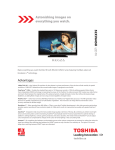
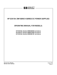
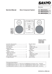
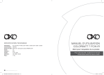
Plug positioning and orientation
on the power supply PCB may vary
slightly from model to model but
pin outs and plug numbers will
remain the same.
CN30
CN720
CN740
Main PCB
P801A
Power Supply PCB
SMART2009-LCD909-V5 Page 2 of 14
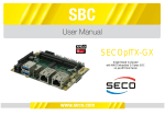
Interconnect CN730
1. Power Key
2. ADC In2
3. Gnd.
4. ADC In1
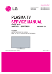
CN651
CN652
LVDS
LVDS
1-5 12V
Vcc LCD
37-41 12V
Vcc LCD
CN653
To Inv.
CN91
Main
Key:
Pin 1
Flow:
>-Out
<-In
** Indicates Standby
CN90
CN30
To Spkrs.
CN720
Logo Pwr.
7. NU
6. GND Inv.
5. BL Det. 0V<
4. NU
3. PWM>
2. Dim SW (0-3.3V)>
1. BL On/Off 3.3v>
8. Vcc 12V LCD<
7. Vcc 12V LCD<
6. Gnd.
5. Gnd.
4. Pwr. LCD3.3V>
3. AC Det. 3.2V<
2. Pwr. Sig. 3.3V>
1. Pwr. Prot. 3.2V<**
14. Gnd.
13. 5V1<**
12. Gnd.
11. 12V<
10. 12V<
9. 12V<
8. Gnd.
7. C Pwr TV (RY3.3V)>
6. Gnd.
5. NC
4. 18V Aud.
3. 18VAud.
2. Gnd.
1. Gnd.
Inverter(s)
Master
Slave
Slave not used on some models
P860
1. 24V
2. 24V
3. 24V
4. 24V
5. 24V
6. Gnd. Inv
7. Gnd. Inv
8. Gnd. Inv
9. Gnd. Inv
10. Gnd. Inv
P861
PJ90
Power Supply
PJ91
AC In
N
P801A
L
Plug positioning and orientation on the power
supply PCB may vary slightly from model to model
but pin outs and plug numbers will remain the
same.
4. L+ Amp
3. L- Amp
2. R+ Amp
1. R- Amp
2. On/Off
1. VCC 5V>
CN740
To IR Rec
and LEDs
15. Gnd.
14. Gnd.
13. Gnd.
12. On Timer LED> 3.3V
11. Stand By LED>
10. Pwr. On LED> 3.3V
9. 3.3V TVM (IR/LED)
8. Gnd.
7. NU
6. NU
5. 3.3V TVM (IR/LED)
4. 5V1>
3. Gnd.
2. IR Out>
1. Rmt. In<
SMART2009-LCD909-V5 Page 3 of 14
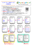
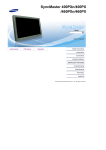
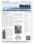
Dead Set No
Sound/ No
Picture
Yes
Yes
Yes
Does
the secondary
12 volt source appear
at pins 9, 10, and 11 of
CN90 when the on/off
button is
pressed?
Does a blink code
appear when the unit is
turned on?
No
Suspect a
problem with the
Main module.
Does
a 3.3 volt DC
level appear at pin 2
of CN91 when the on/
off button is
pressed?
Is
5 VDC present
at pin13 of CN90 on the
main module when AC is
applied?
No
Suspect a problem with
the power supply module.
No
Suspect a problem with
the power supply module.
No
No
No
Yes
Is a
power protect
level (3.2 VDC)
present at pin 1 of
CN91 when AC
is applied?
Yes
Does
3.2 volts (AC
Detect) appear at pin
3 of CN91 when
power is
pressed?
Yes
Use the blink code chart to help diagnose the
problem. Over voltage( Mode 20) indicates
power supply problems and bus line problems
(Mode 19) indicates a defective main module.
Suspect a problem
with the SYSCON
circuit located on the
Main module.
SMART2009-LCD909-V5 Page 4 of 14
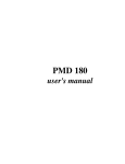
No or distorted
video
YES
NO
Does
the back light function
normally when the unit
is turned on?
YES
Is the
screen discolored
or have streaks as
shown in the example or
are dark areas
present ?
NO
YES
Troubleshoot for
backlight problelms.
Replace
the Main
Module.
This signal viewed from
the twisted cable pairs at
the LVDS connectors
while referencing cold
ground.
Examples
If the LCD Control
Board is available, try it.
If this does not help,
replace the LCD display
panel. ***
When
the input button
is pressed on the
receiver or remote, is
the on screen
display clear and
normal?
YES
NO
Using the
power distribution
diagram, are the voltages
normal at pins 9, 10, and
11 of CN90 and pins
7 and 8 of
CN91?
Check for LVDS activity at
CN651 and CN652. If it is present,
suspect a problem with the display
control board (Tcon). If it is not
present, replace the
main PCB.
NO
Suspect the
power supply
module.
SMART2009-LCD909-V5 Page 5 of 14
Backlight
Troubleshooting
NO
NO
Replace the
Power supply
module.
NO
Is
24 VDC
at pins 1 through 5
of P860 and 12VDC at
pins 7 and 8 of CN91
present while
the unit
is on?
Remove
AC, and unplug the
LVDS cable(s) as well as
P860, and P861. Do both
voltages return when AC is
reapplied and
the unit is turned
on?
YES
Replace the
display. ***
Does
the back light
function and then
turn off or is there a
dark horizontal area
on the
screen?
YES
If it is
available , try one or both
inverters. If this does not
help, replace the LCD
display. ***
YES
Is 3.3VDC
present at pin 1 of
CN653 shortly (.5 sec)
after the unit is
turned on?
YES
NO
Replace the
Main module.
SMART2009-LCD909-V5 Page 6 of 14
No Audio
NO
Using
the remote or
the manual keyboard,
access the audio menu to
assure the speakers are on
and the input selection is a
known good source.
Will this restore
audio?
YES
Problem
solved.
NO
Replace the
power supply
module.
Does the
power supply
generate the audio
supply voltages (18 VDC)
at pins 3 and 4 of CN90
when the
unit is turned
on?
YES
Replace the
Main module
SMART2009-LCD909-V5 Page 7 of 14
ADJUSTMENT
Service Mode
Entering to Service Mode
1. Press MUTE button twice on the Remote
Control.
↓
2. Press MUTE button again and hold button
down.
↓
Service Mode display
3. While holding the MUTE button, press MENU
button on the TV.
ADJUSTMENT
Service Mode
Displaying Adjustment Menu
Press MENU button on the TV.
Service Mode
Press ↑ ↓ Press
Adjustment Mode
ADJUSTMENT
Service Mode
Key Function in Service Mode
The following key entry during display of adjustment menu provides special functions.
Test signal selection
button (on Remote)
Selection of the adjustment items Channel
Change of the data value
Volume
(on TV or Remote)
+/- (on TV or Remote)
Adjustment menu mode ON/OFF MENU button (on TV)
"RCUT" selection
1 button
"GCUT" selection
2 button
"BCUT" selection
3 button
"CNTX" selection
4 button
"COLC" selection
5 button
"UVTT" selection
6 button
Self diagnostic display ON/OFF
9 button
ADJUSTMENT
Service Mode
Selecting the Adjusting Item
Every pressing of CHANNEL button in Service Mode changes the adjustment items in the
order of table below. ( button for reverse order)
SETTING & ADJUSTING DATA
[ SERVICE MODE ]
ADJUSTING ITEMS AND DATA IN SERVICE MODE:
Data
Item
Name of adjustment
40XV645U 46XV645U 52XV645U
R-CUT R CUTOFF
0FH
0FH
0FH
(a)
G-CUT G CUTOFF
00H
00H
00H
(a)
B-CUT B CUTOFF
00H
00H
00H
(a)
R-DRV R DRIVE
7CH
7CH
7CH
(a)
G-DRV G DRIVE
78H
78H
78H
(a)
B-DRV B DRIVE
86H
86H
86H
(a)
BRTC BRIGHTNESS CENTER 74H
74H
74H
(a)
COLC COLOR CENTER
A4H
A4H
A4H
(a)
UVTT BASE BAND TINT
7BH
7BH
7BH
(a)
CNTX CONTRAST MAX
7FH
7FH
7FH
(a)
OPT1 TV SET OPTION 1
00H
00H
00H
(b)
OPT2 TV SET OPTION 2
00H
00H
00H
(b)
OPT3 TV SET OPTION 3
E0H
E0H
E0H
(b)
OPT4 TV SET OPTION 4
6EH
6AH
6BH
(b)
OPT5 TV SET OPTION 5
00H
00H
00H
(b)
8CH
8DH
8EH
(b)
SET-ID MODEL ID
(a) Seine Data
(b) TV-Micro Data
ADJUSTMENT
Service Mode
Adjusting the Data
Pressing of VOLUME
+/- button will change the value of data in the range from 00H to FFH.
The variable range depends on the adjusting item.
Service Mode
Setting Panel Option and Model-ID Data
Panel Maker
Model
OPT3 OPT5 Model-ID
TOP
XV645U
OPT4
Size
Running change TOP Running change
40
SAMSUNG
-
6EH
-
E0H
00H
8CH
46
SAMSUNG
-
6AH
-
E0H
00H
8DH
52
SAMSUNG
-
6BH
-
E0H
00H
8EH
Exit from Service Mode
Pressing POWER button to turn off the TV once.
ADJUSTMENT
Service Mode
Flow Chart of Replacing Main Board
ADJUSTMENT
Service Mode
INITIALIZATION OF MEMORY DATA
After replacing Main board, the following initialization is required.
1. Enter Service Mode.
2. Select "SET-ID" by pressing CHANNEL or CHANNEL button during display of
adjustment menu in Service Mode.
3. Change the data to Model ID of the TV set by pressing VOLUME
+ or
-.
4. While holding RECALL button on Remote Control, press CHANNEL button on the TV.
The TV goes to standby mode.
5. Turn on power of the TV, then the initialization is completed.
6. Enter Service Mode and select Version Check Mode. Confirm if the model name and
MODEL ID is correct. If not, repeat from 1. again.
Note:
If wrong MODEL ID was set, abnormal display might appear.
ADJUSTMENT
Service Mode
Self Diagnostic Function
1. Press "9" button on Remote Control during display of adjustment menu in Service Mode.
The diagnosis will begin to check if interface among IC's is executed properly.
2. During diagnosis, the following displays are shown.
Explanation
Data Format
1 Version information of TV-MICRO
Display 1 byte data.
2 Version information of TV-MICRO EEPROM
Display 1 byte data.
3 Total brightness hour of TV
Display 4 bytes data.
4 V-MICRO System status
not used.
5 IIC-BUS status
None is normal.
"SCL-GN" (Red indication)
SCL-GND short circuit
"SDA-GND" (Red indication)
SDA-GND short circuit
ADJUSTMENT
Service Mode
Version Check Mode
1. Press "9" button twice on Remote Control during display of adjustment menu in Service
Mode. Press cursor button and then the version of main MPU will begin to check.
2. During Version Check, the following displays are shown.
Explanation
Data Format
1 TV model name
Display model name strings
2 TV model ID value
Display 1 byte data.(Hex)
3 Image Verification File
name
Display directory path and file name of Image Verification file
4 Boot Code version strings
Display version strings
5 Core SW version value
Display *.*.*.* format (* is decimal)
6 Seine SW Version
Display *.*.*.* format (* is decimal)
7 Version information of TVMICRO
Display 1 byte data.
8 Version information of TVMICRO EEPROM
Display 1 byte data.
9 EDID Checksum
Pass/Fail Result Listed for HDMI 1-4 (left to right)
10 Global Data Version
Display version strings
11 LCD Panel Opt
Panel Option (OPT4) Data: Display 1 byte data. (Please see
page 8, SETTING PANEL OPTION and MODEL-ID DATA)
12 Factory Test Status
Optional Data Bits that can be used by factory
ADJUSTMENT
Service Mode
LED Indication
The green and red LED lights on the TV indicate the TV's status, as described below:
LED
Combinations
Mode3
LED1
LED2
PowerOn/Standby
OnTimer
TV Conditions
Green/Red/
Green/Red/
Orange (G+R)
Orange (G+R)
Green
Green
Power ON
OnTimer is set
Program Timer is NOT set
Power ON
Mode6
Green
Off
OnTimer is NOT set
Program Timer is NOT set
Power OFF (Standby)
Mode13
Orange
Green
Power-On Mode: Fast
OnTimer is set
Program Timer is NOT set
Mode14
Mode15
Power OFF (Standby)
Power-On Mode: Fast
Orange
Off
Off
Green
OnTimer is NOT set
Program Timer is NOT set
Power OFF (Standby)
Power-On Mode: Saving
OnTimer is set
Program Timer is NOT set
Power OFF (Standby)
Mode16
Off
Off
Power-On Mode: Saving
OnTimer is NOT set
Program Timer is NOT set
Mode18
Mode19
Mode20
Mode21
Mode22
Mode23
Mode24
Mode25
Green Blink
(3 Times)
Off
Booting (Transition from Standby to
On)
For Service
Green Blink
Red Blink
Off
IIC BUS Error
Off
For Service
Power Protect Error
For Service
Off
Orange Blink
Green Blink
Off
Fan Stop Error
For Service
Back Light Error
For Service
Orange
Green
SW Upgrade in Progress
For Service
Red
Green
Off
SW Upgrade Failed
Off
For Service
SW Upgrade Successful
ADJUSTMENT
Service Mode
Update of SEINE SOFTWARE
1. Turn off power of the TV.
2. Prepare a USB memory storing the update software data.
3. Insert the USB device into the USB terminal at the right side of the TV.
4. Turn on power of the TV while holding Menu button on the TV.
5. LED indication is displayed as following,
Mode18 → Mode23 → Mode25 (If update is failed, Mode24 is shown.)
Refer "LED Indication" for each mode.
6. Turn off power of the TV.
7. Remove the USB memory from the USB terminal.
8. Turn on power of the TV.
9. Perform reset of the TV.
9-1. Press Menu key. ("MENU" is displayed.)
9-2. Select "SETUP Menu".
9-3. Select "Reset TV" and press the ENTER key. ("Reset TV Menu" is displayed)
9-4. Select "YES" and press the ENTER key. (Reset operation starts.)
10. The TV goes to standby mode after the reset opration is completed.
11. Turn on power of the TV.
12. Software update is completed.