1
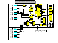
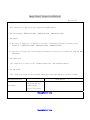
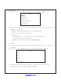
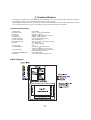
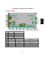
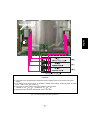
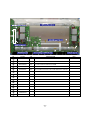
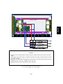
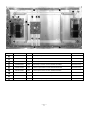
+5V Power Supply (Vcc)
LVDS (Signal Input)
Va Power Supply
Vs Power Supply
External Power Supply (5V, Va, Vs)
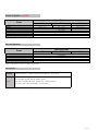
<Caution>
(1) The power of the signal generator should be turned on before turning on the power of DC power
supply.
(2) The voltage of DC power supply, in standard of Module input voltage, should be preset as below.
(Vs : 190V, Va : 60V)
(3) The power of power supply must turned on by this sequence. Reverse direction When turning off.
* Module on : 5V Va Vs, * Module off : Va Vs 5V
(4) Signal generator should be selected with 1366 x 768(Fall in with 60X5A)mode.
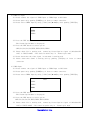
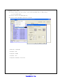
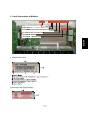
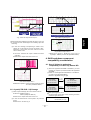
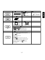
(Fig. 1) Connection diagram of measuring instrument
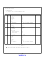
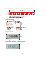
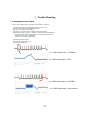
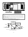
1'st SF
The V set_up setup voltage
and the Waveform voltage
never coincide
(Setup voltage 260V)
V set_up Waveform
Voltage : 240V
Vs Voltage :
190V
GND
-Vy voltage : -65V
180 sec
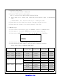
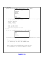
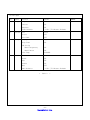
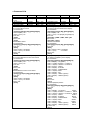
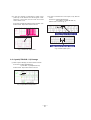
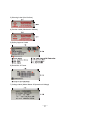
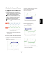
The voltage waveform of the above figure must be adjusted in the Full White screen.
(Fig. 2) Y SUS Adjustment Waveform
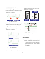
Vscvoltage : 100V