1
. Adjustment
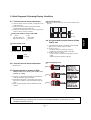
This standard is applied to the PDP42X3#### PDP Module
which is manufactured of PDP promotion department or
elsewhere.
2. Notes
(1) Without any special specification, the Module should be at
the condition of preliminaries more than 10minutes before
adjusting.
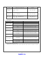
Service signal : 100% Full White signal
Service DC voltage : Vcc : 5V, Va : 60V, Vs : 180V
DC/DC Pack voltage : Vsc : 120V, Vzb : 100V, -Vy : -200V
Preliminaries environment : Temp (25 5°C), Relative
humidity (65 10%)
(2) Aging shall be performed of module in order for
characteristics stabilization after completion of assembling
adjustment. Conditions of aging are as follows.
Service signal : 100% Full White, Red, Green, Blue pattern
signal(Service time of each pattern : within 5minutes/cycle)
Service DC voltage : Match the voltage with the set up
voltage in the first adjustment.
Aging time : More than 4Hrs
Aging environment : Temp (25 2°C), Relative humidityLess than 75%
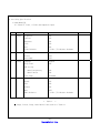
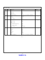
(3) Module adjustment should be followed by below sequence.
Initial voltage setting.(Vs : 180V, Va : 60V, Vcc : 5V)
Vscan Voltage adjustment (120V)
-Vy Voltage adjustment (200V)
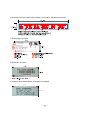
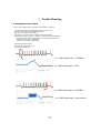
Y set_up Waveform adjustment.
Y set_down Waveform adjustment.
Vzb Voltage adjustment (100V)
But the above item may be altered by consideration of
mass productivity.
(There shall be consultation and agreement of Research
Office / Development Office / QA / Production
Department in case when altering sequence order.)
(4) Without any special specification, you should adjust the
Module in the environment of Temp (25 5°C) and
Relative humidity (65 10%)
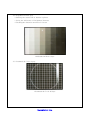
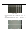
Caution) If you let the still image more than 10 minutes(especially
The Digital pattern or Cross Hatch Pattern which has
clear gradation), after image can be presented in the
black level part of screen.
3. Adjustment after Assembling
3-1. Using Tools
Conditions of aging are as follows.
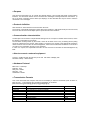
(1) Digital oscilloscope : More than 200MHz
(2) DVM(Digital Multimeter) : Fluke 187 or similar one
(3) Signal generator : VG-828 or similar one
(4) DC power supply
- DC power supply for Vs (1) : Should be changeable
between 0V to 200V/ more than 10A
- DC power supply for Va (1) : Should be changeable
between 0V to 100V/ more than 5A
- DC power supply for 5V (1) : Should be changeable
between 0V to 10V/ more than 10A
- DC-DC Convertor Jig(1) : Vs, Va, 5V Jig with
corresponding output to each voltage Pin arrangement of
PDP42X3#### Module after the input of voltage.
- Voltage stability of power supply : Within 1% for Vs/Va,
within 3% for 5V
3-2. Connection diagram of measuring
instrument and setting up the initial
voltage
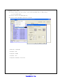
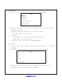
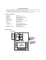
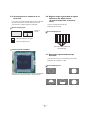
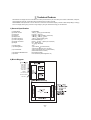
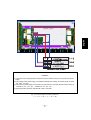
(1) The Connection diagram
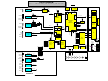
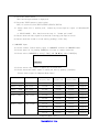
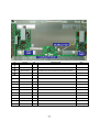
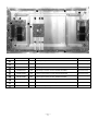
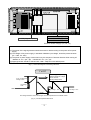
Refer to (Fig.1) Connection diagram of measuring instrument.
(2) Setting up the initial voltage : Refer to Voltage Label
Vcc : 5V, Va : 60V, Vs : 180V
But, Initially setting up voltage can be changed by the set
up range according to the Module’s characteristic.
3-3. How to Adjust
1. Connect the measuring instrument to be (Fig.1).
2. How to adjust Y SUS( Adjustment should be done
after setting Vs/Va to the set voltage)
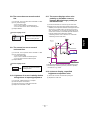
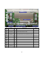
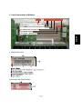
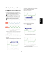
(1) -Vy Voltage adjustment
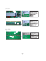
Measure and adjust the voltage between -Vy TP on top
of the DD_pack on theY SUS B/D .
Turn the variable resistor of -Vy DD_pack(PS101) on
Y SUS B/D to set to (-200 ±0.5V).
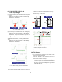
(2) Vscan Voltage adjustment
Measure and adjust the voltage between Vsc TP on
right of the P4 on the Y SUS B/D .
Turn the variable resistor of Vscan DD_pack(PS102) on
Y SUS B/D to set to (120 ±0.5V).
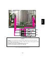
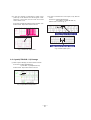
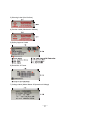
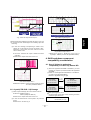
(3) Connect the oscilloscope probe Waveform
point on Y DRV B/D and the GND.
English
1. Application Object