1
SERVICE MANUAL
T-500
SERIES
T-524
T-582
T-546
T-595
NOTE: For all
other T-Series
serv ice n formal ion, ref e r
i
to
H 000 -000431
CAUTION
SEE SAFETY NOTICE ON
INSIDE COVEH SHEET
HOOO-001270
SECTION
I
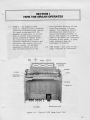
HOW THE ORGAN OPERATES
1-1
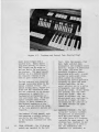
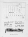
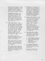
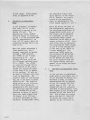
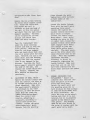
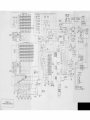
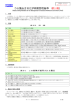
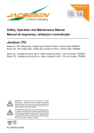
GENERAL - The Hammond T-500
Organ J-s completely self-contained,
requiring no external tone cabinet.
The organ is equipped with two
manuals, or keyboards^ of ^A keys
each, a 13-note pedal keyboard,
and an eKpression (swell) pedal
Eor controlling output volume.
Seventeen adjustable tonebara and
six preset tabs enable selection
An automatic
of tone colors.
1-2
programable rhythm unit with
auto chording feature is the
,i(5stf
™ebu^
Mfnni
diatinsuishing function of this
organ froio previous T-Seriea
organs. The reroainine musical
variations are controlled by
tablets and knobs provided. A
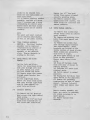
switch (See figure 1-1 .) controls
power to all motor and electronic
circuits in the organ. A pilot
lighc indicates when the
instrument is powered,
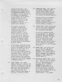
TONE SOURCE - All tones of the
organ originate as electrical
cnmiBtwas
inrTfffHTCBWTEHinm
1 PBAl ILEKT
vmt
Ul
laEBIE
HULLIL
ciuanE
PtH.EFlfCT& b
LOVER UNJJL
ntn
lErsihWD
Figure 1-1.
EVPHlSSKll CONIROL
VHUHt
Typical T-500 Organ Front View
I-l
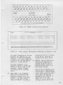
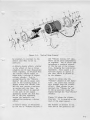
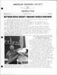
VIBRATO Lirtf BOX
mUTQ
DfrUPI
IU>HHIR
AUTO CHOAD BOARD
TREMOLi} Uhir
POHIB TERMINAL
PAnEL
CHOSSCrtfi NETWORB
EXPflESSia* PEDAL
ENCtOSED
REVCftBESATICM UNIT
TRtMOO PlUG
TONE CABINET ITECEFTAClE
'fVCiS EHAT IG N £
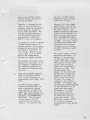
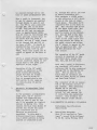
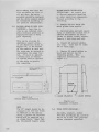
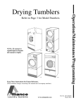
Figure 1-2,
Typical T-500 Organ, Rear View
signals In the tone generator
assembly.
It contains 74 tone
^rfieels having various numbers of
teeth, with suitable gears for
driving them at various speeds from
a main shafc extending along the
center.
Each pair of tone wheels
is mounted on a shaft and between
them is a bakellte gear held by a
coil spring forming a mechanical
vibration filter. As the gear is
not rigidly attached to the shaft,
any pair of wheels which may be
stopped accldently will not
interfere with the operation of
the others
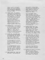
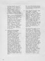
Adjacent to each tone «heel is a
magnetized rod with a pick-up
coll wound on it. These magnets
extend through the front and back
1-2
POWa AAI FlIFER
of the generator, and are held by
set screws which can be loosened
in case adjustment is ever
necessary^
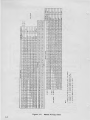
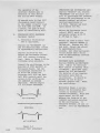
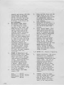
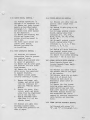
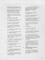
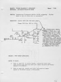
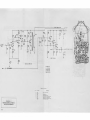
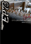
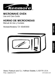
Figure 1-3 shows where
to find the magnet for any frequency number.
In this drawing the
dotted lines indicate frequencies
^ose tone wheels are on the same
shaft.
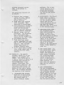
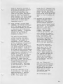
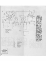
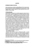
On top of the tone generator assembly are small transformers and
condensers, forming tuned filters
for the higher frequencies.
They
are not likely to need replacing.
In case one filter becomes inoperative, both the transformer and
condenser must be replaced with a
matched set from the factory.
Figure 1-^ shows the location of
these filters.
e^
^
e
§)
'^ '^ \o A@ \e V® \® \& \@ IQ
r^
issi
rSii
sSi'
«i> et»
'^,'1
^
1
^
e e e e e e e e
ei
tnfpDF UtdPiTVi
l'P«CHH»4<A
"
}^
/iSi
i^l"
-
t7^
:?)
'^"^
f^'l
'^ ^
^\
®\ ®\
@\ @\ /^
@\ 1^
r^"<
/^Ti
^
^ ^63) ^
7
DOITID lllUt 1-*M 'fHaCMTia
Figure 1-3,
I
1
^
'^
^
^
&n
"HOt
Ep)C
tnOLI JK
Um ^-UTT
Q»J
Magnet Location on Tone Generator
^
aKH
IVKbl^n
l.iXiiiJi.i^
*l li
Figure
-fl
l-'i.
-^
t
iiHIi
ii
it
H
*i !t ^'
U'liaSEin
ta
ii
kr
r-
!• t<
"
I* .f
ii
i*
Jf
^
It
H
4.
1-
n
:t
W
ip
*1
u
[a
n H
H J>
ip
4
^^
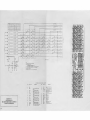
Filter Location and Frequency Termlnatilon on Generator Cover
The output frequencies of the cone
generator are numbered^ for convenlence^ in order of increasing
frequency. The lowest^ number IS,
1-i
is about 87 Hz, and the highest,
number 91, Is about 6000 Hz.
The output terminals of the
generator consist of solder lugs
mounted on the back edge of the
generatorFigure 1-i shows
the terminations by frequency
number.
1-3
*
Bi l' is ••
PEDAL TONES - The fundamental
pedal tones are derived from
generator frequencies nos. 25
through 37 by means of dividers
mounted on the Pedal Divider
board, 124-000178. The derived
frequencies are nos. 1 through
13 for the 16' pitch and 13
through 25 for the 8' pitch.
MAJIUALS - Musical frequencies
from the tone generator go
through the manual cable to
terminal strips on the two
manuals and from them to the
key contact springs.
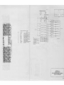
Each of the two manuals has 44
playing keys, or approximately
The two manuals
3 1/2 octaves.
do not cover e^tactly the same
pitch range, but they are
arranged so that the keys of
like pitch are in line.
Middle "C" is the first C on
Che upper manual and the key
1-3
in line with it on the lower
ttsaual.
Under each key are a numbex
of contact springs (foe the
fundamental and harmonics of
Chat key) which touch an equal
number of bus bars when the key
(Some keys at the
is pressed.
end
of
each
manual have
right
fewer springs, as noted in
Fleure 1-5) All contact springs
and bus bars have precious metal
contact surfaces to avoid corrosloo, and the manuals are sealed to
ejcclude dust so far as possible.
In case a contact becomes dirty in
spite of these precautions, a bus
bar shifter is provided in each
manual to slide the bus bars
endwise and thus provide a fresh
con tact surf a ce
The busbar shifting mechanism
for the lower manual will be
found by looking on the underside left-hand end of Che
manual.
A black wood end
block will be observed.
One-haLf inch from the front of
this block is a drilled hole.
Within this drilling is a
GENERftTOR
KHEffUEHCT
^PRINtS
PEOAL
^EYER
DARDS
PFll*L
SWITCHED
COhNECTOR
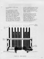
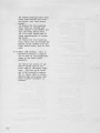
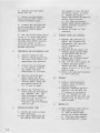
Figure 1-6.
Pedal Keyboard
1-5
Figure 1-7.
Tonebars and Contrcl Tabs (Partial View)
small petal tongue with a
Using either
puisched hole.
pliers,
or a hook,
long ngse
this toague can be moved In
and out and It in turn moves
The upper manual
Che busbars.
shifter 1b in a similar place
but requires removal of the
back to gain access to it.
The key contacts are connected
through resistance wires to the
manual terminal strips- The
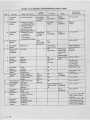
manual wiring chart, Figure 1-5
shows how the contacts of each
key are connected to the proper
frequencies to supply fhe
fundamental and harmonics of
The blank
that particular key.
spaces indicate that no key
contact is used, inasmuch as
the highest harmonics of the
highest keys are above the range
of the tone generator and are not
required.
The busbars of each manual, each
one carrying a certain harmonic,
are fed to bus amplifiers, then
to the harmonic tonebars for that
manual
1-5
1-6
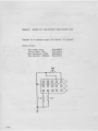
PEDAL KEYBOARD - The 13 playing
pedals are operated by the left
foot. Like the manuals* they
have light and dark keys
arranged in the standard octave
pattern.
Figure 1-6 identifies
the pedals and shows the
generator frequency number
associated with each. A pedal
contact on each pedal closes
when a pedal is pressed,
allowing the correct generator
frequency to reach the pedal
tonebar amplifier. As the
pedal switches are in a series
arrangement, only one pedal
If two pedals
plays at a time.
are pressed* only the lower
pedal will speak. When the
pedal Is released, the last
played pedal note continues to
sound for a length of time,
determined by the position of
the PEDAL SUSTAIN and PEDAL
LEGATO tabs.
1-6
HARMOMIC TONEBARS - The left
group of 7 harmonic tonebars
(Figure 1-7) is associated
with the lower manual, and
the right group of 9 tonebars
controls the upper manual. By
sliding these tonebars in and
out, the organist is able to
miK the fundamental and
harmonics (or overtones) in
various proportions- The
distance a bar Is pulled out
determines the strength of the
corresponding hamonic; and if
a tonebar is set all the uay In,
the harraontc it represents
is not present in the mixture.
Neither manual will play
unless at least one of its
ronebars is pulled out part
of the way, with the
TONEBARE tab pressed, or a
preset tab Is pressed.
1-a
The conebars slide over
9 busbars, representing
intensity levels, and each
tonebar "has two contacts
connected together by a
5600 ohm resistor.
As the
tonebar moves, at least one
of the contacts is touching
some busbar at all tinies» and
therefore there is no "dead
spot" in the tonebar motion.
The 5600 ohm resistor avoids
fin actual sho^t circuit between
adjacent busbars.
1-9
These busbars extend the length
of the tonebar assembly but are
split in the mtddle to form two
groups of 9 (see Figure 5-1.)
Those in the left group,
under the lower manual tonebars
are connected to the base of the
transistor Q-351. Those on Che
right group, under the upper
manual tonebars, are connected
to the base of transistor Q-85^
through the upper manual TONEBAR
& PERCUSSION tablet.
1-7
PEDAL TONEBAR - The center
tonebar adjust the volume of the
pedals by sliding over 9 busbars
mechanically segregated from the
upper and lower manual busbars.
The output from this busbar is
fed in parallel with the
signal from the lower manual to
the base of transistor q-S51,
EXPRESSION PEDAL - The "expression" pedal, sometimes called
"swell" pedal (Figure 1-1), is
operated by the player's right
foot and varies the volume of
both manuals and pedals together
When the pedal is tilted back
(closed) by pushing on the
player^s heel, the music is
softest, and when pushed
forward (opened) by the player's
toe, the music is loudest.
CONTROL TABS - There are 23 tabs
OQ tlie T-5O0 series Instrument,
each providing some change in
the instrument's operation.
To have the instrument sound
after turning it on, tabs such
as THEATER BRASS and ENSEMBLE
will place the upper and lower
manuals in operation. A tab
is in use when in the down
position.
Functions of the
various tabs from left tft right,
as they appear on the Instrument, are given in the following
paragraphs
1-10 PRESET TABS - Two preset tabs
ate provided for the lower
manual; namely, TONEEAES and
ENSEMBLE.
Four preset tabs are
provided for the upper manual;
namely, TONEBARE and PERCUSSION,
STRINGS S', FULL TIBIAS 16',
THEATER BRASS 16'
1-11 PERCUSSION CONTROL TABS - There
are 7 tabs lAich control percussion. These operate in either
the up or down position of
the upper manual TONEBARS fi
PERCUSSION tab. When the
TONEBARS & PERCUSSION tab Is
up, percussion only is played
on the upper manual; when the
tab is down, tonebar effects and
percussion are played
simultaneously.
For tonebar
1-7
bass pedals, a normal decay
and attack axe heard when the
pedal tonebar is pulled out.
Either IS' or 3' pitch ia
available by means of the
PEDAL a'/l&' cablet.
effects alone on the upper
manual^ Che seven percussion
tabs must be in up posttton,
and the TONEBAES & PERCUSS I CW
Cah muac be down.
1-12 VIBRATO TABS - The T-Series
instruments are equipped with
four Vibrato tabs to vary the
An additional
Vibrato effect
tab (VIBRATO ON) to the left
of Che vibrato group permits
the vibrato effect to be
introduced inimediately.
Various vibrato effects are
available by use of the Cabs>
Vibrato Celeste III la
achieved by depressing both
VIBRATO CELESTE I AND II Cabs.
Use of the PEDAL LEGATO
tablet provides a very slow
pedal decay which many beginners
find useful, as the pedal last
played sounds until the next one
PEDAL SUSTAIN
Is played,
causes the pedal tone to decay
slowly.
PEDAL MUTE gives
added deep tone to the pedals
when desired. Further Information concerning
electrical function Is given
In paragraph 2-5.
.
1-13 REVERBERATION - Three degrees
of reverberation are obtained
by the use of either or both
tabs labeled REVERB I and
REVERB II. These tabs. In
addition to Cuming this
feature on, govern the loudness
or amount o£ reverberation.
1-H
VOLUME SOFT, BRILLIANCE TAB,
AND REITERATION RATE CONTROL
The VOLUME SOFT tab controls
the overall volume of the
organ and Is useful uhen
playing might disturb others.
The BRILLIANCE tab in the up
position bypasses a portion of
the higher frequencies to
ground, making the organ sound
deeper.
The REITERATION RATE control,
as the name Implies, adjusts
the rate or speed of reiteraclon when used in conjunction
uith the percussion tabs aad
reiterate cab.
1^15 ?£DAL ROCKER TABS, LOWER LEFT
END BLOCK - Upon playing the
1-3
1-16 TREMOLO ROCKER TABS, lower
LEFT EHD BLOCK The TREMOLO
ON/OFF Cab connects the
organ signal to the Tremolo
speakers when "on". The
TREMOLO SLOW/FAST tab controls
the speed of the Tremolo, which
runs whenever the organ is "on".
,
1-17 AUTO CHORD BOARD (12i-000179)
The Auto Chord Board contains
the gating circuits for lower
manual and Hi/Low Bass of the
pedals.
This board is not
independent functioning as it
needs keying or gating pulses
from the Rhythm III unit.
The different auto chord modes
are selected by the Rhythm III
switching circuitry.
If the Auto Chord Board is
removed the pedal and lower
manual voicing is silenced
1-lB CASSETTE 121-000139 & 121-000165
This unit is 1/3 track
monaural cassette transport
deck..
It features controlled
electronic speed regulation
and automatic level control
patterns. Two or ffiore
rhythm patterns may be
played simultaneously
if desitedj including
3/4 and 4/4 time rhythm
patterns
mtnizing distorted recordings, A microphone is
Included.
The operational features are
as follows
A. Keyboard type transport
B.
C.
D.
E.
F.
G.
contiol for Stop» Rewind^
Fast Forward S Play/
Record functions
Thumb wheel type playback
level adjustment. (Nonfunctional in record mode)
Electromechanical accidental
erasure-prevention system
keyed with Eecord/Play
controls and rear knock-out
tabs on cassette cartridge.
External access jack for
Microphone. The microphone
has a motor start-stop
switch and when plugged in,
disconnects the "Aux." Input.
Lid loading cassette.
Thumb wheel type speed
control adjustment with red
mark on knob denoting center
position.
This red mark
allows rapid return to
standard cassette speed,
In the record mode of operatlon^ output signal must be
disconnected from output
terminals
1-19 RHYTHM III - The inbuilt
automatic Rhythm III is contained in one assembly 125000082. This rhythm unit is
a step-up version of Khythm 11-A
containing such features as
Auto -Accompaniment output
signals, Touch-Start, Foot
Switch Preset capability, and
four play-a-long voices. All
player-operated controls are
mounted on the Inbuilt Rhythm
Unit. The following describes
the function of the controls.
A.
PROt^LAMMED PUSH BUITOHS,
There are 15 interlocking
push buttons mounted on
the control panel to
select different rhythm
Bi SILENT/SOUND - The Silent/
Sound tablet is used to
silence the audio output
fat the automatic rhythm
voices (but not the
follow-the-player voices)
and reset the timing
generator when it is moved
to the Sound position.
C. CONTINUOUS /TOUCH START -
The Continuous /Touch
Start switch allows the
player to start the
rhythm unit from either
the lower manuals or pedals
by first placing this
tablet in the Touch Start
position, second, move
the Silent /Sound rocker
switch to its Sound
position, and then depress
either a lower manual or
pedal key
D.
FOOT SWITCH RESET - The
Foot Switch Reset tablet
allows the player to
either just silence the
audio output (Including
Che follow-the-piayer
voices) when the food
switch is depressed or,
lAen the Foot Switch
reset position, to
also reset the generator
when the foot switch Is
released.
E. AlJrO ACCOMPANIHENT -
The Auto Accompaniment
suitch when placed in the
"on" position, provides
gating signals for the
lower manual and for high
and low pedal gates.
If
Reset
the Foot Switch
is
in the "off" position,
the foot switch does not
1-9
aiiect Auto Accompaniment.
If Che Foot Switch Reset is
In the "on" position, the
foot swicch silences Che
Iou?r manual and pedals,
because the pulsing cracks
are not available Co
operate the 3 gates.
Turning "on" the Auto
Accoinpaniment swi C ch
disables Che Pedal Sustain
Tab and the Pedal l6Va' Tab.
F. TEMPO LAMP - The Tempo Lamp
blinks beats (4 beats per
Dteasure) when the rhythm
unlc is silent and blinks
nteaaures «hen the rhythm
unlc Is "on". If the Foot
SwiCch Reset is in che "off"
posiclon, Che £oot switch
does not affect Che blinking
lamp.
If Che Foot Switch
Reset is in the "on" posicion
the foot switch operation
causes Che lamp Co blink at
che beat race.
1-10
G.
TEMPO CONTROL - The tempo
knob concrols che rate of
the rhyChm unit from 48 Co
300 beats per minute. The
cempo knob also has a Lamp
Off posicion to turn off
the Tempo Lamp when che
rhyChm unit is not in use.
U.
VOLUME CONTROL - The
Volume Control is a dual
contral which varies the
output level of both the
high frequency and the low
frequency output channels
simulCaneously
I.
BASS DRUM & CYMBAL - The
Bass Drum and Cymbal
Cablecs allow the player to
activate these voices by
depressing a pedal key on
che organ.
These voices are
controlled by che volume and
can be silenced by the
expression pedal kick switch.
^^
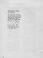
SAFETY NOTICE
Gr«ii care
Jiaa
»eri lehen
Bfioch Fiozarfl BkljlH
iHi arty
Jn irts
deAiQn ana TiAru'ftciure oi rhig prodiM;! id anura inai no
rrktlal cam. internal ssrvKa Dpareriani cin «ipo3a II10
a'poHd
lacTiniGJan in rtaiaiOoui Lfna vDiiagn irid Kcidgr>iaiiy cbum inaH vaitagn lo aaoev on
uposaa matai pvisdurJriQrfipdirtM-raBEBambiyai proaudcoTicwnanii. To preveni ihia. wofh
ih«e prwiLicts irtc^uid oniY
pfirTmrnad Dy rhue wj^d an iFLcrouDhiy lomiiiHT Miin ir>«
pracBulluiia noHuary fhan naii<\nQ on in Is lyp« ol ^guLpmBn.
»
n
To
proiocr ihouior,
thvir criglnil
tfM Qianar
Pliil]
ihft
it li
rtquirvd ihai
condU^vn *vf FIm
akiranr •rrl»
AC
Tramlormsf
Ilr4
ill
iDllafrlng
rtcraaurt parii ind Mftiy Inivriocti bi rHinrwi
iHtk b« p«rlarm*d balort rtlurnlnfl lli« piodLKE
u
Id
Dfi4raTlD(l.
cord dlfoclly Into P iJia voliaae AC roceptacJe |do nol uh ar> miallon
fMi] and lurn H>fl prMud on, Cormoci ifiB HBiirfirK (aa an&*n belo") In
lor ihia
H»poMdmaiBipArt9irid«hrio»rieariharaunaaucnasa waitrplpoor cunduJIUaaan AC VOM ol S.om onms p«i voltoi hiaheraanHlilvll, to rnusure IM^ voU^ge ijrapacaaa
TtM nfllworK. Uove 1^ noiwork connBcilan To Mcn a^pMO-J moial pan imaFal tHaaaps, icraw
hea^s, Knoos and conifoi aha'iB. aacurcnson, erc.i una rneaaura iha vniiag* flrop acrou tno
noiwurk RavorM iris Una pikio and rop»t ifvB rnHaHuramenla An, rewlng 0' * woUa HW5 or
puiemiHi artock nutrd wnich musi ub cwracEoa bafora
mora la aicauive and indicaiH
serieiwiriiart
nlufnlng Uie proiJucl lolEie uui
CVmFCTtD TO
El FTTH ERDUHfl
Tfl
[JPDSEl
iEUL
fl.»TS
#Dn
SECTION II
THEORY OF OPERATION
M*tihtT
"^St^^
OUTPUT
VI0H4TQ SHALL TABLET"'
IP4PUT
iO-liOlS Of VIBJ9A10 LINE
e:
V3BHATO
OtOAA'
T.^B^
Figure 2-2.
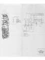
FmidaJnental Diagram of Vibrato System
the output frequency
the average remaining equal to Che
input frequency.
»
The exact amount of frequency
shift depends not only on the
amount of phase shift in the
line but also on the scanning
Figure 2-3.
2-2
rate. This race, however, la
constant because the scanner is
driven by the synchronous running motor of the organ.
The 'Vibrato Small" tab varies
the amount of frequency shift by
causing one half of the line Co
Vibrato Line Box
Figure 2-4,
Typical Drum Scannei:
be scanned, in contrast to the
entire line when In the up
position
A vibrato chorus effect, similar
to the effect of ti*io or three
slightly out-of-tune frequencies
mixed together, is obtained when
the vibrato output signal is
mixed with a portion of signal
without vibrato. This is
accomplished by the "Vibrato
Chorus" tab, which causes only
part of the incoming signal to
appear across the vibrato line
and the rest across a resistor
la aeries with the line.
As
the vibrato effect is applied
to the pa.rt of the signal
appearing across the line but
not to the part appearing
across the resistor, the
combinaticn producer a chorus
effect.
A celeste effect Is obtainable
by the use of "Vibrato Celeste I"
,
and "Vibrato Celeste II" tabs.
These can be used Independently
or together.
Use of these tabs
introduces a resistor network
at the far end of the vibrato
llne» changing the termination
impedance. This causes a re-^
flective signal to appear in
the line, which Is picked up
by the scanner.
Figure 2-2 shows only the
"vibrato" channel of the amplifier.
All tones sent through
this channel have the vibrato
effect. When vibrato is not
desired, the "Vibrato On" tab
in the up position feeds the
signal through the "non-vibrato'
channel
Figure 2-3 shows the vibrato
line box.
It is mounted on the
rear of the upper manual.
The scanner Is mounted on the
left end of the generator and
2-3
The voice mesh mentioned selects
the proper concent and ampllcude
of each harmonic necessary for a
particular voice.
is driven directly via an "O"
ring from Che tone generator
Clin motor.
It is a raultl-pole
variable capacitor with 16
equal stationary aegmenta and
a rotor. Connection to the
segments are made by 16 snapFigure 2-i shows
on contacts
construction
of the scanner.
the
2-5
^
Signals coming from the vibrato
line appear on the stationary
segments and are picked up, one
at a time, by the rotor.
Connection to Che rotor is made
by graphite brushes as shown
in Figure 2-4.
When assembled,
graphite brushes iniEt be no
closer Chan 1/16" from outer
end of contact pin or brass
sleeve. Adjustment may be made^
if necessary, by bending legs
of the brush lug.
Brushes
should not concacc each other
In operation.
2-4
2-4
MANUAL BUS BAR AMFLIFTEES^
124-000015 S 124-000016
(See figures 5-3 & 5-4)
The busbar amplifiers for both
manuals are located to the
rear of the control panel.
The lower tnanual board
contains one amplifier for
each of the seven harmonic
bus bars. The outputs of
these amplifiers are routed
to the tonebars and voice
The upper manual board
mesh.
contains one amplifier for
each of the nine harmonics.
Amplified signals are fed to
Che tonebars and three preset
voice meshes.
All the amplifiers have a response curve designed to decrease the amount of
key transientA typical bus
amplifier receives its input
signal from the busbar. The
signal is amplified and sent to
the proper tonebar and/or voice
mesh.
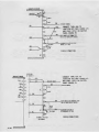
PEDAL KEYBOARD AND SWITCH, FEDAL
KEYER BOARDS, 124-000025.
124-000026, 124-000027 (See
Figure 5-6) - The pedal keyboard
and switch assembly is located
under the power and reverberation
amplifier. Three pedal keyer
boards. No. I, 2 and 3, are also
mounted on Che switch assembly.
Board 1 contains the keyers for
the five lowest pedal notes
(25 through 29).
Board 2
contains Che keyers for the pedal
frequencies #30 through ff33 and
Board 3, the keyers for frequencies #34 throu^ tf37. This
provides one keyer for each
pedal note
,
All pedal keyers operate In the
same manner.
Following is a
typical function, involving the
lowest pedal (C)
Switch S-751
is closed, placing +15V on C-751.
This voltage forward biases Q-753
through resistors E-756 and B-757.
This allows the generator signal,
present at pin 6 to pass to the
eoimltter.
All emitters are
common on the boards and provide
the input signal to the high
pass active filter network
located on pedal keyer board ff3.
Board rfl also contains an erase
circuit and buffer stage, working
In conjunction with all pedals.
Whan any pedal is pressed, a
negative pulse is coupled
across C-750 to the base of
q-750.
This negative pulse
reverse biases Q-750, causing a
positive pulse to appear at the
collector. The positive
pulse passes through D-750 and
forward biases Q-75]
resulting in a negative going
.
'
,
pulse to ground at the base of
Q-752 and the cathodes o£ pedal
diodes D-751 through D-763,
This is the erase pulse and
turns off any pedal keyer which
does not have its associated
pedal pressed. The buffer stage
Q-752 transfers the positive DC
signal from the keyer and the
erase pulse to other organ
functions at pin 8.
2-6
PEDAL DIVIDER & FILTER BOARD
ASSEMBLY. 12^--00017& (See Figure
5-7) - The Pedal Divider and
Filter Board Assembly is located
on the power and reverberation
amplifier diassls.
It provides
aiDplificaCion, shaping and
division by four bistable
frequency dividers.
The amplifier and shaping
circuit receives its input
signals from the pedal keyer
circuitryThe signal Is
amplified by Q-70i, q-702 and
Q-703.
Shaping is accomplished
by q-70A and Q-705, uhich
furnishes a +12V square wave at
the Input frequency to the first
divider bi-scable, Q-706 and
Q-707 make up the first bi-stable
The
or flip-flop configuration
Input slgna] is divided by 2 and
appears at the collector of
q-707. This signal will become
the 8* component of the pedal
signal uhen called for by the
positive DC signal from the
Auto Chord hoard. The DC signal
forvard biases D-702 which
allows the signal to pass
to output pin ffl2.
The signal
at the collector of Q-707 also
becomes the input to the
second bistable.
.
(J-70& and Q-709 make up the
second divider.
The signal Is
again divided by 2, and will
appear at the collector of
Q-709.
This signal will
become
called
signal
board
biases
signal
2-7
the 16' component when
for by the positive DC
from the Auto Chord
The DC signal forward
D-701 which allows the
to pass to output pin
RECOVERY AND fJON-VlBRATO
BOARD, 12^-000014 (See
Figure 5-A) - The recovery
and non-vibrato board is
located on the control panel
and consists of two recovery
amplifiers. One recovery
amplifier handles the
sigjials from the pedal
tonebar, lower manual
tonebars and presets. The
other handles the signals
from the upper manual tonebars, and presets. The
board also contains the
non-vibrato amplifier and
intermediate amplifier
(with click filter) which
drives t:he main amplifier.
The recovery amplifier
receives its signal from
input pins 6 or 8.
The
signal is amplified by
Q-851 or Q-852. and the
outputs appear at pins 5
and 7.
These outputs are
tied together and sent to
the "Vibrato On" tablet
located on the control
panelf where the "Vibrato
or Won-Vibrato" mode will
be determined.
With the "Vibrato On"
switch in the Off position
the pedal and both manual
signals appear at pin A,
The signal is amplified by
q-e53 and sent to the
intermediate ampllfer
and click filter.
The Intennediate ampll-
2-5
fler receives iC3 signal
from pin 9 in the vibrato
mode or from R-S60 in the
non-vibrato mode. It Is
amplified by q-354.
The remai-nde r of
the circuitry acts as a
click filter with the
output appearing at pin 3.
The output of the entire
board is controlled by
potentiometer R.-S70
that also serves as
"system" volume
adjuatraent
2-8
Vl&EATO BOARD ASSEMBLY,
124-000018 (See Figure
5-6) - The vibrato board
assembly Is alao located
on the control panel.
It controls the vibrato
drive and vibrato
recovery amplifiers.
The vibrato drive amplifier receives its signal
at pin 1 from the "Vibrato
On" switch. This signal
is amplified by a low
noise transistor Q-SOl,
followed by further
amplification by Q-802,
and q-803 (the latter an
emitter follower).
Final
amplification is by q-804
and transformer T-801.
Output to the phase shift
is from pin 4.
The vibrato recovery
circuit receives its
input signal at pin 3
from the vibrato scanner-
The emitter follows Q-e05
Q-806 and Q-807, present
3 high reactive impedance
to the scanner with the
output appearing on pin 7.
2-9
SWELL PEDAL CIRCUITRY The main organ signal
input to the Rower Amplifier board (124-000017)
is at pin S. Pin 10 of the
board is connected to the
LDR located on the Swell
Pedal assembly (133-000004).
The LDR provides a variable resistance to ground
to vary the amplitude of
the input signal.
2-LO POWER AND REVERBERATION AMPLIFIER ASSEMBLY - The power and
reverberation amplifier assembly is DKiunted on the pedal
keyboard and switch assemblyIt contains the power supplies
the swell pedal circuitry, the
main amplifier, the reverberation drive and recovery, and
the previously mentioned pedal
divider and filter board
assembly.
MAIN AMPLIFIER, 124-000176
(See Figure 5-8) - The resulting signal at C-601 is amplified
by Q-601 passed to the base of
Q-602. The signal is then
amplified by Q-602 and transferred
to the primary of T-601 tbrougb the
Darlington configuration emitter
follower Q-603 and q-604. q-605
and Q-606 Is an "AB" type
amplifier and the output to the
speakers appears on pin 19.
REVERBERATIOT DRIVE
The
reverberation drive gets its
3-6
signal from the emitter of Q-601.
The signal is amplified by Q-607
and Q-608 and transferred to the
primary of T-602
Q-609 and
Q-610 is an "AE" type amplifier
and the output appears at pin 2&,
,
REVERBERATION KECOVERY. The
output from the reverberation
unit appears on pin 4,
The
signal is amplified by Q-611
and Q-612 and appears at pin 6.
The reverberacton signal then
goes through the reverberation
tab circuitry and appears as an
input at pin 12
2-11 POWER SUPPLY CIRCUIT - Power
supply components are located in
Che power supply chassis assembly (127-000176 thru -000178).
All necessary DC supply voltages
for the rhythm jnit are supplied
by this chassis.
The voltages
are +15V DC, +1SV DC, +23V DC,
+25V DC and -25U DC. 120V AC
50/60 Ha is supplied to the
power transformer from an
external source. The secondary
AC voltage Is 27V RMS,
D601 & D602 rectify the
secondary voltage C615 filters
it and -25V DC appear at the
oucpuc of this circuit.
2-12 PHONE JACK - T-500 organs are
equipped with an earphone
jack, which will give pleasing
results.
Use headsets such
as Clark 200, Koss 3P-3XC, or
Sharp HA-10
When earphones
are plugged in speakers are
disconnected for listening
privacy. Tremolo effects are
not heard in earphones.
,
2-13 SPECIAL POWER SOURCES - T-500
organs are made to operate on
the voltage and frequency
specified on the nameplate.
They are available for
117V/60 cycle - 117V/50
cycle - 23iV/50 cycle and
234V/60 cycle.
If the
unit is moved to an
area having voltages or
frequencies other than those
specified on the nameplate,
consult your local dealer
concerning changes required
foe conversion.
2-14 PERCUSSION BOARD ASSEMBLY
(124-000170) - The following inter-related circuits
are located on this board
(See Figure 5-10)
1.
2.
3.
D603
D604 rectify the secondary voltage C6i6, R644 filter
+25V DC. 15V zener D608, R645,
C117 regulate and filter the
+15V DC supply,
&
4.
1 1/i Harmonic Generator
Normal Percussion Keying
Reiteration Keying and
Triggering
Main and Alternate
Channel Gates
f-
D605 & D606 rectify the secondary voltage and the combination
of C618, L601, C619A, R643, and
C619B filter the supply voltages
of +25V DC, +23V DC, and
A.
1 1/4 HARMONIC GENERATOR
The output of this circuit
is used only aa part of the
chimes voice.
The circuit receives its
input at pin 11 from the
+18V DC,
2-7
upper manual 5ch hacmonic
buss amplifier.
The signal
is amplified by Q514, Q515
and q5l6. The resultant
square wave output provides
the Input to IC501,
IC501
is a *J-K Flip Flop integrated circuit.
The collector
supply voltage for the IC
and Q51fc Is a result of the
action of D12, a 5 vole
Zener diode
The output from 1C501, pin 8
±3 coupled to a uaveshaping
network and to the output
pin 14.
*J-K Flip Flop - IC 510 is a
single package two stage bistable divider.
Failure of
one stage requires the
replacment of the IC package.
Several pins of the IC package are not used in this
circuit application.
B.
2-e
NOKMAL PERCUSSION KEYING In the fionnal percussion
mode, when a key is depressed
on the upper manual, 220K
ohms of resistance are
connected between pin 15 and
ground. As a result, the
positive voltage at pin 15
is reduced.
This negative
change is differentiated by
C517 and applied to the
base of Q512 (normally on).
The resulting positive pulse
at Q512 collector Is coupled
to Q513, turning it on.
The
negative change, at the
collector of Q513, is coupled
by C510, forward biasing D509
and D510.
C511 is also
charged.
Since the pulse used
to charge C511 is momentary,
C511 begins to discharge
immediately
With the Guitar and Chimea
switch in the off position^
pin 10 is grounded- The
discharge path of C511 is
split.
One path is through
D510, R537, and the combination of Q510 and q5ll.
The
other is through D511 and
R5i6 to ground. This provides for the short decay
time. When either the
Chimes or Guitar switch is
depressed, the ground is
removed from pin 10 and the
second discharge path is
opened. The result is a
longer decay tlrue.
The entire action will be
rekeyed when an additional
key Is depressed.
The voltage
at the input will drop in
increments with each key depressed and result in an
output pulse fed Co Q5i0 and
Q511.
This type of keying
is referred to as Legato
type percussion,
REITERATIOM KEYING AND
TRIGGEEIWG - When Che
reiteration tab is depressed,
the percussion keying busbar
in the upper mariuaJ is connected to pin 2. With
normal percussion, it was
connected to pin 15,
When an upper manual key is
depressed, a 220K resistor
connects pin 2 to ground.
This causes the base of
transistor Q501 (normally
off) to drop from +23 volts
to approximately +22,5 volts
which causes it to conduct.
The collector of Q501 rises
to +23 volts.
The +23 volts
is routed to pin 4, which
is connected to the reiter-
atlon rate control on the
control panel, and also to
the top of R506.
the base of Q507 supply
sufficient bias co cause
conduction of Q511,
Pin 4» through to the
wiper of the telteration
coi>trol, which is connected
to pin 18, Che voltage is
fed to R508 and R509. The
varying voltage applied to
pin 18 causes the astable
multivibrator (Q506 and
(J507> to vary tn frequency.
Through Q511, two signal
paths exist, one for the
gating signal and one for
The
the music signal.
usable portion of the music
signal passes through the
base collector junction of
q5ll, through R556 (Main
Null Control), to the base
of Q509
The music signal
is amplified by Q509 and
controlled as to amount
of output by the setting
of R557 (Percussion Level
Control).
Froin
.
The positive 23 volts applied
CO E506 causes D502 to be
forward biased. This action
brings the junction of R506
and D502 to a positive 15
volt level. This 15 volts
causes D503 to be forward
biased and subsequently
becomes the supply voltage.
The outputs are taken alternately from the bases of the
multivibrator transistors.
The negative pulses drive
Che main and alternate gate
circuits.
D.
MAIH Am ALTERNATE CHANNEL
GATES - The main channel
gate circuit consists of
transistors Q50e, Q509 Q510,
Q311.
,
As Q506 and q507 (MulCivibrator transistors) conduct alternately pulses
from Che base of Q507 are
supplied to the emitter of
Q511, the gating transistor^
and Q510, a grounded base
amplifier. The AC signal
on the base of Q511 is
Insufficient for qSll to
The pulses from
conducts
»
The gating signal, as was
mentioned previously, is
applied to the emitters
of qSlO and Q511. The
signal which goes through
Q511 appears at the collector with the music
signal and is applied to
the base of Q509
The
gating signal also
appears aC the collector
of q510 and is directly
coupled to the base of
q503.
From the emitter
of qSOS, the signal is
coupled to the emitter
of Q509.
The signal from
the emitter of Q509 appears
at the collector out of
phase with the signal
impressed on its base.
As a result, the two
gating signals are out
of phase and cancellation takes place- The
Main Null Control (R556)
Is to affect maximum
cancellation of the gating
pulses.
.
2-9
The operation of the
alternate channel gate is
identical as that described for Che main channel.
Of special note is that R557
(Percussion Level Control)
is the oommon collector load
As
for both Q502 and Q509.
a result, the gain of both
gates Is controlled by R557.
E.
PERCUSSION SETLC? PfiDCEDURE
Equipment Needed:
1,
Tektronics Oscilloscope
503 or equivalent.
Depress the "REITERATE" tab
and set Reiterate Rate control
at approximately mid poaltioo.
Depress and hold key tf25.
Rotate the Percussion control
R557 full counter clockwise
Refer to Figure 5-10 for
(up)
folloulng setup procedure.
PERCUSSION AND REITERATION GAIN
Depress "CELESTA" tab, depress
"REITERATE" tab and place control In approximate lald position
Connect the oscilloscope to the
speaker terminal and adjust
vertical sensitivity to
1.0 V/cm.
Depress end hold
upper manual key fl25.
Adjust the Percussion Level
control (R557) until the
percussion output is 10. 5U
+ .3V Peak to Peak.
Return all tabs to their "off"
position.
Depress CHI^TES or
GUITAR tab. Depress Key tf 25
And hold. Decay time should
be approximately three
seconds. All other percussion
voices should have a decay
time of approximately one-half
to one second.
.
Connect the oscilloscope to the
junction of C503 and fi527 on
Percussion Board, Set the
oscilloscope sensitivity to
10 [nv/cm and rotate the
Alternate Null R519 and Main
Hull R556 controls until the
pulses on the oscilloscope
are adjusted to minimuia
amplitude.
Observe Figure
2-5 for proper waveshape.
4
i-
KOT flCCtPTflBLE
ACCEPTaeiE
h-t
mi
2-10
flccEPToeiE
Figure 2-5
Percussion Null Adjustment
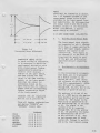
REITERATE RATE ADJUSTMEHT
Depress CELESTA and REITERATE
tabs.
Adjust the Reiterate
Rate control to maximum {full
clockwise). Hold down upper
manual key fl25 and measure
the duration of one complete
percussion wave form on
oscilloscope. It should be
between 45 and 65 milliseconds (Figure 2-6). Reset
the oscilloscope.
Horizontal Sweep .1 sec/cni.
Adjust the Reiteration Rate
control to minimum (full
counter-clockwise)
Hold down
upper manual key fr25 and
measure the duration of one
complete percussion waveform
on the oscilloscope.
It
should be between .10 and .45
seconds. Turn off REITERATION
.
tab,
*NOTE
There will be a mismatch In chimes.
The 1 1/4 harmonic present in the
upper Dianual chimes voice is not
available in the lower manual Tonebar registration.
Ey disconnecting
the orange lead at pin ffl4 (1 1/4
haimonic output) on the Percussion
Board (12A-000170), a perfect
match should be obtained.
2-15 AUTO CHORD BOAED (124-000179)
A.
SLOU RATE
Figure 2-6
Percussion Decay AdjustmenC
'^^
PERCUSSION PRESET VOICES
To check voicing of percussion,
it Is necessary to match the
upper loanual percussion voice
with a lower manual Tonebar
registration by playing a
chord in shore staccato
fashion on the upper manual^
and then playiag the same
chord, in the same staccato
manner, on the lower manual.
Note that the output for
percussion voices on the
upper manual will be slightly
higher than the corresponding
Tonebar registration output
of the lower maniial.
Tonebars that are registered
will be set at position flS.
Clear all tonebar regist rations
and depress "CELESTA" and
"TOHEBARS" (lower) tabs.
TOHEEAHS
VOICE
CELESTE
CHIMES *
GUITAR
MARIMBA
XYLOPHOHE
BANJO
12
3 4 5 6 7
8
8 8 8
3 8 8 8
8
8
8
8
S
1.
Non-Autochord Manual Mode
The lower manual input signals
are connected to pin 4, through
C? to base of common emitter Ql.
For a 5inv input signal* approximately X5niv appear on the
collector Ql. This signal is
fed through C3 to the base of
transistor Q5, which is part
of the gate and differential
amplifier circuit consisting
of Q2.
2.
HOn-Automatic Accompaniment
Mode
In the non-automat ic accoropani-ment Diode, pin 11 is grounded
by a switch contact in the
Rhythm III unit. This causes
the collector of QIO to switch
from OV to approMimately -19VDC.
This DC level is connected
through R37, D2, RIS, RU to the
emitters of gates Q4 and Q5The emitters
£
Q4 and Q5 are
now at --5VDC due to the emitter
base junction and Q4 and Q5 are
turned on. The signal on the
base of Q5 is amplified by Q5
and fed through Rll to the base
of q3.
The signal on the
emitter of Q3 is connected
through R18, R6 to the emitter
of Q2.
Q2 aniplifies the signal
to approximately ?00 mv P-P
on Che collector of Q2.
This
is fed through part of level
control R5, through C4 and R12,
and to the lower manual preamp
S
8 8 8
2-11
the amplified signal once
again appears at the output
pin 6, however the output
occurs at the repetitive
rate» as determined by the
track signal applied to pin 7.
Lower manual
in Che organlevel is adjusted by R5.
,
B.
Autoniatle Accompaniment
Hode
Since Q2 and q3 are part of
the differential amplifier,
the resulting undesirable DC
change which could occur at
the output can be adjusted
Co a minimum, so that only
the desired audio signal
variation can be seen at the
output collector of QZ.
Also,
each time a key is depressed
the resulting DC level change
at pin 9 is fed through CIO
to the base of Q9, which is
The
a pulse amplifier.
resulting -20VDC pulse on
the collector of Q8 is fed
through pin 10 and is used
by Che Rhythm III unit for
the touch response mode and
for legato keying from Che
manual of the Brush and Snare
Drum voices-
In the automatic accompaniment mode, pic II is not
connected to ground in the
Rhythm III unit. The
appropriate track, differentiated ouCput is connected
to pin 7 of the Autochofd PUB.
This is approximately 1 ms
wide -5V P-P spike, which is
connected through £24 to the
base of q?.
When Che player depresses a
lower manual key, pin 9
becomes connected to ground
through a 220K resistor.
The -20VDC at pin 9 rises
approximately 2V. This
changes the bias of Q8 and
its collector switches from
OV to -20VDC, The -20VDC
is connected through K23 to
the collectoc of Q7, which
allows the repetitive spike
on the base of Q7 to appear
on its emitter.
Q7 acts as
an emitter follower each time
The
a key is depressed.
negative spike is fed through
R21, D3 Co Che base of pulse
amplifier Q6. The positive
going spike at Che collector
of Q6 ia fed through C6,
integrated by R15 and C5 and
the resulting negative pulse
is fed Through R14 to the
emitters of gates Q4 and Q5,
Since Che input signal from
the manual Is at the base
of Q5 (as described in uonautomacic accompaniroenc mode),
2-12
C.
^
1.
Hpn-AutQ Accompaniment Pedal
Mode
In the non-auto accompaniment
pedal mode of operation, pin 15
is not grounded by Rhythm 111;
and when a pedal is played,
approximately +9V is applied
to pin 19, through DIO, R49
and to base of Q16, QI6 is
Cumed off and its collector
switches to approximately -15V.
This signal is fed through R46
Co base of Q15 and turns off
Q15.
Q15 is used as a ooise
gate, and when it turns off
it allows any signal which
appears on its collector to
20, through R52 and to the base
of switch transistor Q17.
This produces a +15VDC pulse
on the collector of Q17, which
occurs at the rate of input
track pulse. The pulse is DC
coupled by R55 to the base of
Qie,
This switches Q13 on-off
at the input track rate, and
the resulting
to 15 volt
positive pulse is fed through
C13, D12 and R58 to the base
of Q19.
QX9 turns "on" and
"off" at the input track rate
and this biases the diode iiL
the pedal circuit and allows
the 8' signal to appear at the
base of amplifier Q20. C13
and R57 determine the "on"
time period.
be coupled tKrougli C15 to the
base of pedal preamplifier Q20.
When a ptdal Is depressed, the
8' and 16' signals are applied
through diodes to pins 21 and
13.
The +9V is also connecced
tbroueh R50» D13 co the base
of Q19, This positive voltage
turns on Q19 and its emitter
rises to approxtmatiely +SVDC.
This DC level is fed through R59
and it provides forward bias for
the diode from the pedal S'
divideri and the 8' pedal signal
is fed through Ii60 and CL5 to
It should be
the base of Q20.
remembered that Q15 noise gate
was also turned "off" by the
+9VDC, which thus allows the 8'
signal to appear at the base of
Q20.
,
The operation of the 16" pedal
circuit is identical to that
described above except that
Q12, Q13, and qi4 are used.
Q20 is a common emitter amplifier,
and its collector output is connected back to the pedal preamplifier in the organ.
Operation of the 16' pedal
circuit is identical to the
above stated description,
except <31i must be turned
"on" by bias on diode D7.
This is accomplished by the
16/S switch in the organ as
it connects pins 15 and 14
Each time a pedal is depressed
the resulting -20V pulse on
collector Q16 Is also connected
through R51 to the Rhythm III
unit.
This is used in the
Touch Dtode of operation and
used for pedal keying of Cymbal
and Bass Drum Voices'
tog^Cher.
2.
Automatic Accompaniment Pedal
Mode
In the automatic accompaniment
pedal mode, the 8' and 16'
signals are connected once
again to pins 21 and 18, but
pin 15 is grounded by a switch
contact In Rhythm 111.
This
removes the bias from diodes D7
and Iil3 but allows the noise
gate transistor Q15 to
function as previously
described. In this mode a
differentiated track (depending on which pattern is being
played) is connected to pin
The collector of Qll is connected to the sustain circuit of
the console.
When operating
Rhythm HI in the Auto
Accompaniment Mode, Qll is
turned "on" and removes the
15 volts from the sustaining
circuit. This disables the
Pedal Sustain rocker switch.
2-16 CASSETTE 121-000139 & 121-000165
Performance Specifications
(Electrical)
A,
Record/Play Response:
With 70 m v applied to "Auh.
Input", record 50 Hz followed
by 6K Hz using Philips TC-R
2-13
D,
cassette and using a 100 ohms
load resistor at playback
output^ with volume level
set for 1.0 volt* the 50 He
and the 6K H3 output shall
be within -6 db using IK Hz
as a refecence.
ALC Dynamic Range OutpuC
and Hgrmonic Distortioni
1.
Uith 40 mv at 1 K Hz
applied to "Aux. Input" and
using Philips TC-R or equivalent cassette and using
100 ohms load resistor at
playback output, record for
approximately 1 minute.
Adjust playback level for 1,0
volt; the total hainfonic distortion shall not exceed 5%.
With 1.2 volts at 1 K Hz
2,
applied to "Au>i, Input^' and
using Philips TC-R or
equivalent cassette and
using 100 ohms load resistor
at playback output, record
for approximately 1 minute.
Adjust playback level for
1,0 volt; the total harmonic
distortion shall not
exceed 5%.
Signal to Noise Ratio an.d
Apply
Miniinuni Output Level:
215 m V at IK Hz to "AuKInput" and connect 100 ohms
load resistor to playback
Using Philips TC-R
output.
or equivalent cassette,
record for approximately
Adjust level
1 minute.
control during playback for
1.0 volt rms.
Output level
rust drop a minimum of i*0 db
at end of recording.
Power Supply: Use -6VUC
supply + 10%
E.
150
175
175
200
B.
Play
Record
Fast Forward
Rewind
.
2-U
.
.
,
.
.
.
.
.
.
ma
ma
ma
ma
Nominal
F.
G.
Noise and Hum: Noise and Hum
output shall be less than
.06V on playback with volume
at maximum with cassette
cartridge in play mode with
tape stopped.
Erase Head Efficiency:
Minimum of -35 db erasure of
AOO Yiz saturated recording
with 60 ma of erase head
current
Speed Control Range: With
speed control mid position
fred mark on knob) the tape
speed of standard cartridge
Philips TCFL3 or equivalent
shall be 1-7/8 ips +3%.
With speed control in
maximum counter-clockwise
position^ the tape speed
+3%.
shall be -10
With
speed control in maximum
clockwise position^ the tape
speed shall be +10 +3%.
Slowly turning the speed
control through the entire
range shall provide a smooth
change in speed.
2-17 RHYTHM III - Theory of Operation
A.
MASTER OSCILLATOR - The master
oscillator is a relaxation
oscillator controlled by a
programm-^ble unijunction transistor (PUT). The rate is
controlled by varying the
charging current for CI
through the control panel
mounted potentiometer. The
output of the oscillator
drives a buffer transister,
which in turn drives the
first stage of a five-stage
counter.
COUNTER - The five stage
counter is made up of 3 dual
J-K, DTL flip-flops. Onehalf of IC 3 is used to
provide pulses (at a beat
rate) to the lamp one-shot
only when stages 2 chrough
5 of the counter are reset
by Q3 and Q6.
The fivestage counter normally
counts to 32 before
When either
restarting.
the Waits or the Slow Rock
rhythm patterns are called
for, Che output of the fourth
divider is fed back to the
third divider through q6.
This feedback pulse will
cause the counter to restart
after a count of 24. The
output of the fourth divider
is also used to trigger a
one-shot through R21 and C34,
which drives the tempo lamp
at a measure rate.
C
.
TOUCH STAET CONTROL - The
Touch Start circuit is a
set-reset bistable comprised
of transistors Q8 and Q9 and
reelacors RSii through R7i,
The output of transistor QS
provides signals for voice
gates on the Voicing Board
(124-000180) and also for
generator gating circuits
controlled by transistors
Q7 and QIO.
When a positive input pulse ia
applied to Jl-2 (reset input),
transistor Q8 provides a
ground signal that turns
off the voic^e gating circuits
(Jl-B) , and Is inverted by
transistor Q7. Transistor
Q7 provides a positive signal
to transistors Q3 and Q6
which reset counter stage 2
through 6 and enable the beat
rate divider (Fin 9 of IC 3),
When a positive pulse is
applied to any one of the
three "start" inputs (Jl-1,
Jl-11, Jl-12), the set-reset
bistable changes state, which
enables the voice gates to
open, reiaoves the reset
signals from the counter
stages 2 through 5, turns
off the beat rate divider,
and provides a reset pulse to
the first stage of the counter
through capacitor C4.
D.
DIODE MATRIX - The outputs
from the counter are decoded
and differentiated by a
diode/capicitor matri^t to
form specific pulse sequences.
The diode matrix has 21 output
tracks wlilch are fed to the
Rhythm Selector Board.
E»,
fiHYTHM VOICES - There are
eight rhythm voices used in
this rhythm unit. They are
Bass Drum, Lo\i Conga, High
Conga, Claves, Snare Drum,
Brush, Cymbal and Maracas.
The Brush, Cymbal, Maracas,
and the high frequency part
of the Snare Drum are
generated by shaping and
formanting the output of a
vAiite noise source.
The
White noise is generated by
a reverse biased transistor.
The outputs of the white
noice voices are combined and
fed to a high frequency preamplifier whose output appears
on J4 pin 2.
The remaining voices are
generated by R-C oscillators
uhich are turned on by pulse
amplifiers that provide the
bias current for the oscillators.
The outputs of all of the R-C
oscillators are mixed together
and then fed into a low frequency
pre-ampllf ier whose output
appears on Ji pin I,
The outputs
of both pre-amplifiers are
connected to a dual volume
2-15
control, and the outputs of
the volume control go Co the
on t put conne ct o r
F,
PLAY-A-LONG VOICES - There
are tuo pulse inverter circuits,
which invert input signals from
the lower manual legato trigger
circuit and also from the pedal
touch mode trigger circuit.
The output of the lower manual
inverter (J4-1A) can be
switched to either the Brush
input (J4-14) or the Snare
flrum input (J4-7) by front
panel tabs. The output of
the pedal inverter (J<1-13)
can he switched to either
the Bass Druin input (J 4-20)
or the Cymbal input (J4-i)
by front panel tabs*
2-16
^
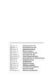
T-500C
TABLE OF CONTENTS
PAGE
INTRO DUCT ION
1
SPECIFICATIONS
iv
SECTION I - HOW THE ORGAN OPERATES
—
1-1
1-2
1-3
General
Tope Source
Pedsa Tones
1-5
1-6
Pedal Keyboard
Harmon! Tonebars
1-8
1-9
1-10
1-11
1-12
1-13
1-1^
1-15
1-16
1-17
1-18
1-19
Expression Pedal
1-7
Control Tabs
1-7
Preset Tabs
1-7
-^
—
1-7
Percussion Control Tabs
Vibrato Tabs
1-8
Reverberation
1-8
Volume Soft, Brilliance Tab, and Reiteration Rate Control— 1-8
Pedal Rocker Tab, Lower Left End Block
1-3
Tremolo Rocker Tabs, Lower Left End Block
1-8
Auto Chord
1-8
1-3
Cassette
Rliythm III
1-9
——-
1-1
1-1
1-3
1-6
1-6
—
—— —
—
SECTION II - THEORY OF OPERATION
2-1
2-2
2-3
2-4
2-5
2-6
2-7
2-'&
2^9
2-10
2-11
2-12
2-13
2-14
2-15
General
Tone Generator
Vibrato System
Manual Bus Bar Amplifiers
Pedal Keyboard and Switch Pedal Keyet Boards
Pedal Divider & Filter Board Assembly
Recovery and Non-Vibrato Board
Vibrato Board Assembly
Expression Pedal Circuitry
Power and Reverberation Amplifier Assembly
Power Supply Circuit
Phone Jack
Special Power Sources
Percussion Board Assembly
Auto Chord Board
2-17 Rhythm 111
—
—
—
—
—— —
—
2-1
2-1
2-1
2-i
2-i
2-5
2-5
2-6
2-6
2-6
2-7
2-7
2-7
-^-^2-7
— 2-11
2-14
TABLE OF CONTEBTS (cont'd)
PAGE
SECTION III - DISASSEMBLY
3-1
3-2
3-3
3-4
3-5
3-6
3-7
3-S
3-9
3-10
3-11
3-12
3-13
3-14
3-15
3-1
General
3-1
Removal of Organ Top
—- —3-1
Upper Manual Key Removal
3-1
Removal
Lower Manual Key
3-1
Assembly
Removal
(Entire
or
Partial)
Tonebar
^-^-3-2
Pedal Tonebar Assembly Removal
3-2
Lower Manual End Block. Semoval
^
-—
_—
—3-2
Caaaetce Kensoval
-^3-2
Upper Manual Removal
—3-3
Lower Manual Removal
-^
^—
3-3
Tone Generator Removal
3-3
Power Amplifier Removal
'3"3
Pedal Sustain Keyer Removal
______—— 3^3
Pedal Switch Assembly Removal
-""'
3-4
Music Lamp Removal
—
^— —
———
—
'
~—
—
——
'
'•
SECTION IV - PRACTICAL SERVICE SUGGESTIONS
4-1
4-2
4-3
4-4
4-5
4-6
—
General
Vibrato Drive and Recovery Board
Tab Replacement —
Tremolo Speaker Maintenance
Raising Organ On Deep Pile Carpet
Overall Organ Level Adjustment
~
———
4-1
^-1
4-1
4-3
4-6
4-6
SECTION V - DIAGRAMS
5-1
SECTION VI
6-1
—5-1
General
-
PARTS LIST
Parts Llac Index
—
PWB Parts List
—~—~—
—^-1
6-15
THRU
6-lS
APPENDIX (Not Included at this time)
A-1
11
Appendlj: IndiK
A-1
'S^
LIST OF ILLUSTRATIONS
FIGURE
1-1
1-2
1-3
1-i*
1^5
1-6
1-7
2-1
2-2
2-3
2'A
2-5
2-6
4-1
4-2
5-1
5-2
5-3
5-A
,^,
5-5
5-6
5-7
5-S
5-9
5-10
5-11
5-12
5-13
5-14
5-15
5-16
5-17
5-18
5-19
5-20
5-21
PAGE
Typical T-5O0 Organ Front View
1-1
Typical T-500 Organ Rear View
1-2
1-3
Magnet Location on Tone Generator
Filter Location and Frequency Temilnation on Generator
1-3
Manual Wiring Chart
1-4
Pedal Keyboard
1-5
1-6
Tonebars and Control Tabs (Partial View)
—
2-1
Typical Tone Generator
^_^_2-2
Fundamental Diagram of Vibrato System
2-2
Vibrato Line Bok
2-3
Typical Drum Scanner
Percussion Null Adjustment
2-10
^Percussion Decay Adjustment <-—
2-11
4-6
Bottom Rail Construction
Placeioeiit of Glides
4-6
5-2
Logic Block Diagram
Lower Manual Bus Amplifier Board
124-000016, Layout and Schematic
5-3
Upper Manual Bus Amplifier Board
124-000015, Layout and Schematic
5-'*
Recovery and Non-Vibrato Board
124-000014, Layout and Schematic
5-5
Vibrato Board 124-000018, Layout and Schematic
5-6
Pedal Keyer Boards 124-000025, 124-O0OO26
124-000027 Layout and Schematic
5-7
Pedal Divider and Filter Board
124-000178, Layout and Schematic
5-8
Power and Reverberation Ajapltfier Board
124-000176, Layout and Schematic
5-9
Power Supply Chasals 124-000176-173, Schematic
5-10
Percussion Board 124-000170, Layout and Schematic
5-11
Auto Chord Board 124-000179, Layout and Schematic
5-12
Special Effects End Block 125-000073, Layout
5-13
Expression Pedal 123-000061, Layout
5-13
Drum Scanner, 066-042874
5-14
Cassette Recorder Assembly, 121-000139 i 121-000165,
Schematic
5-15
Rhythm TIT Block Logic Diagram (125-000082)
—5-16
Rhythm III Generator and Track Gate Board
124-000214, Layout and Schematic
5-17
Rhythm III Selector Switch Board
124-000196, Layout and Schematic
5-18
Rhythm III Voicing Board 124-000130 Layout and Schematic
5-19
Rhythm III Cable Assembly
5-20
Rhythm 111 Output Matrix Timing Chart, and
Voicing Pattern Chart
______5_2i
—
—
—
—
—
—
—
——
——
iii
TNTBDDUCTTON
This tpsnual contains service InEormatlon covering the T-500 Hammond
Organ.
Features of the T^500 are explained in Section I.
Rhythm 111 with Auto Chording of the lower manual and pedal 8' fi 16
voicing are the special features of this instrument. Service
information for Rhythm II and Auto Chording are included in this
service manual.
For convenience in locating desired information,
this manual Is divided Into the sections Hated below.
I
H
111
IV
V
VI
How the Organ Operates
Theory of Operation
Disassembly
Practical Service Suggestions
Diagrams
Parts List
AppendiJC
SPECIFICATIONS
CA£IHET SIZE
45" Wide
25" Deep
44V High uich Music Rack
Weight with Bench
235 lbs.
Power Input
1.2 Amps,
Music Power Out
34 Watts
(Per EIA Standards - RS-234)
tv
SECTION
III
DISASSEMBLY
3-1
3-2
GENERAL - This section
contains instructions for
removal of specific subassemblies from the organ*
as required,
3-4
(a) Remove two mounting bolts
from rear of upper manual end
blocks.
(b) Remove one screw which
passes through angle bracket
into upper manual. This
bracket is located on the
inside surface of the cheek
block on the left side.
This screw is accessible
from the front of organ,
(c) Tile upper manual up
and back.
<d> To remove a Black key,
loosen its key mounting
screw and lift from rearTo remove a White key,
loosen its key mounting
screw and those of adjacent
black keys as required.
REf^OVAL OF ORGAN TOP -
After removing rear panel,
remove two Ecrews from
underside of rear rail
near each end of organ.
Lift organ top at fJEORt to
disengage spring fasteners
on inside of each cheek
panel.
Before lifting top,
disengage plug and ground
wire from Rhythm HI unit,
also plug for music light.
3-3
UPPER MANUAL KEY REMOVAL (a) Remove four screua which
secure metal cover on control
pane 1 ass emb ly
(b) Unsolder Violet and Black
tuisted pair wires, as well as
Yellow and Black twisted pair
Vdlres, terminating directly
behind lower drawbar Cab, which
are connected to drawbar assembly.
(c) Remove two large studs
located on ends of control
panel which secure it to upper
manual
(d) Fold control assembly so
that it rests on shelf,
(e) To remove a Black key,
loosen its key mounting screw
and lift from rear.
-
To remove a White key, loosen
its key mounting screw and
those of adiacent Bl^rk k^vs
LOWER MANUAL KEV REMOVAL -
3-5
TONEBAR ASSEMBLY REMOVAL
(ENTIRE OR PARTIAL) Perform steps "a" through
"d" of Paragraph 3-3.
(aj Unsolder wire from
tonebar contact spring to
be replaced.
Remove fiber
stop retaining screw.
NOTE:
Be certain that thin
insulator is between contact
spring and drawbar.
Replace
contact, stop, and screw
and resolder ulren
(b) To replace tonebar or
tonebar knob; proceed as
above, but do not unsolder
wire. This will permit
3-1
slider to be removed front
front for Its replacement, or
tpob replacement
(c) To remove (Complete tonebar
assernbiy
unsolder all wires
from 17 tonebars and 6 wires
terminating on control panel.
Hemove three hex head screws
toward either end of tonebar
assembly.
Remove two 1/4" hex head
screws from center o£ metal
cassette mounting plate,
(c) Remove cassette cable
connections from console^ tip
front strip for clearance and
remove cassette.
»
NOTE
The upper asid lower tonebars
can be removed individually,
as well as the pedal tonebar.
3-6
PEDAL TONEBAR ASSEMBLY
REMOVAL - The Pedal Tonebar
AssfiTHbly can be replaced
Independently by removal of
two screws securing the
assembly to the phenolic
plate.
Remove assembly by
sliding CO the rear.
3-7
LOWER
frt^NUAL
END BLOCK
fiEHOUAL <a) For left end block,
remove two round head screws
that pass through left side
of lower manual top cover
one inch inside end block.
(b) Remove screw that passes
through angle bracket into
end black.
(c) For right-hand block.
Remove two round head screws
that pass through right-hand
side of lower manual top
cover into end block.
3-3
CASSETTE REMOVAL <a) Remove six (6) philllps
head screws from upper manual
front strip.
(b) Remove one 1/i" hex head
screw from recessed hole in
left front rail trim block.
3-2
3-9
UPPER MANUAL EtEMOVAL (a) Remove four screws that
retain metal caver on control
panel assembly.
(b) Remove two mounting rear
bolts from upper manual end
blocks
(c) Remove two screws that
pass through angle brackets
into upper manual.
These
brackets are located on the
inside surface of cheek blocks
These screws are accessible
from front of organ.
(d) Tilt upper manual up and
block in this position.
Remove upper manual front
strip.
(e) Snap off harness clamp
from left side of manual by
pulling forward.
(f) Unsolder all wires from
terminal strips
(g) Return manual to normal
position.
(h) Unplug bus bar wires from
upper manual at bus amplifier,
(i) Remove all grounding
terminations on rear of upper
manual.
Release 3 plastic
cable clamps and remove line
boK.
Remove tonebar assembly and
base, as a unit, by removing
six screws securing it to
upper manual.
(j) Remove manual from
casework.
3-10 LOWER MANUAL REMOVAL (a) Perform operations "a
Chrough d" In Paragraph 3-S»
(b) Remove two Lower control
panels as described under
Paragraph 3-7. Unplug bus
bar wires from lower manual
at bus amplifier.
(c) Keanove two mountiTig end
blocks and loosen four
screws attaching manual to
front rail.
(d) Raise upper okannal and
remove lower manual.
Reverse procedure for
re-ina Calling.
3-11 TONE GENERATOR REMOVAL (a) Unsolder all harness
connections from the generator terminal strip.
(b) Ranove heavy ground ulre
In center of generator.
(c) Remove the AC cover panel
and unsolder the five wires
from harness.
(d) Remove the four bolts
which secure tone generator
to support brackets.
(e) Remove control panel
cover by removing 4 screws.
1.
2.
3.
Remove the brown, red,
orange, and yellow wires
from the terminals behind the "Vibrato Small"
switch.
Remove the green, blue,
violet, grey, and white
wires from the right-hand
end of the line box.
Unplug shielded cable
from pins 2 & 3 of the
vibrato board.
3-12 POWER AMPLIFIER REMOVAL
(a) Release all cable ties and
plastic cable clamps from
chassis.
(b) Unplug 12-pole plug on top
of chassis.
(c) On large printed circuit
board, unplug wires from
terminals 3-^, 5-6, 7-8,
9-10, 11-12, 19. 20, 27-28,
29-30, 31.
(d) On small printed circuit
board, unplug wires from
terminals 1, 2, 3, i*, 6 (two
wires), 7, S, 9, 10.
(e) Unplug all wires from tenlug terminal strips near
small printed circuit board.
(f) Remove four screws securing
amplifier - two at each end.
3-13 PEDAL SUSTAIN KEYER REMOVAL Pedal Sustain Keyers are
located beneath Power Amplifier Chassis
<a) Release all f!able ties In
the speaker area to the right
of the speaker.
(b) Release cable tie at righthand side of Reverb Unit
(obtain as much slack in
Expression pedal cable as
possible)
( c )
Remove the f ou r sc rews
securing power ar^lifier to
pedal switch base and tilt
back power amplifier chassis.
(d) Pedal Sustain Keyers are
now accessible and can be
removed by removing appropriate
cable harness and mounting
bolts.
3-lA PEDAL SWITCH ASSEMBLY REMOVAL
Release all cable ties
securing scanner leads,
(g) Slide tone generator out
rear of organ.
<f)
(a) Proceed with steps "a",
"d", and "f" of Paragraph 3-11.
3-3
(b) Remove mounCing bolts from
pedal keyer boards {six from
end board, four from center
board)
(c) Kenxove the tuo mounting
bolts which go through the
lower cabinet croas member and
Into the Pedal Switch Base.
(d) TlXt Pedal Ewicch end of
organ approximately 12 Inches
and block.
(e) Remove the four mounting
bolts which come up through the
botCom of Che cabinet Into the
Pedal Switch Base, (two ac each
end)
3-15 MUSIC LAMP REJ*)VAL - When it
becomes necessary to replace
one or more of the incadescent
lamps in the Hualc Light
Assembly.
(a) Remove two pieces of adhesive backed felt at the
front edge of the mualc light
lens.
Tip lens up at front
and slide forward to remove.
(b> To remove lasip or lamps,
depress lamp into socket and
twist counter-clockwiEe to
release.
3-4
SECTION IV
PRACTICAL SERVICE SUGGESTIONS
4^1
GENERAL - This section concalns
maintenance and practical servicing infoEniation. Peculia.r
Cechniques are explained In
detaii.
Procedures which
should be obvious are not
discussed.
4-2
VIBRATO DRIVE AND KECOVERTf
BOARD, P/N 124-000018 The R821 potentiometer is sec
at Che facCory, and will
normally require no adjuscinent.
Do not actempt to
adjust unless absolucely
necessary.
See following
paragraphs
Press down VIBRATO and
BRILLIANCE tabs. Play
upper manual key ffS, Note
voltage on meter. If
voltage is within + 2 db
of reading obtained in
step 2, make no adjustment.
If voltage is at more than
2 db variance with step 2
reading, adjust R821 to
obtain reading identical
to step 2,
i-3
TAB EEPLACE^ffiNT - In the
T-Series organs che tabs
ate suspended on three
pivot rods
However, che
joints becween sections of
rod are concealed by plastic
sleeves, so that to the uninitiated, che appearance
Is that of one continuous
.
Whenever any of che vibrato
circuitry has been serviced,
proceed according to the
following
rod.
Connect a VTVM across
main speaker leads. Press
down the TONEBARS and PERCUSSION tab. All other tabs
should be up. Swell pedal
at full volunte.
1.
'
The rod ends are butted in two
places:
1.
In the space becween
VIBRATO ON and REITERATE
tabs.
Pull upper oianual 8'
tonebar Co position S> Play
key tfS on upper manual.
Note voltage on mecer
(about l.iV rms)
2.
Return 8' tonebar to
position 0.
3.
Pull upper manual i'
tonebar Co poslcion 8.
4.
In che space between
THEATER BRASS 16' and
CHIMES tabs.
2,
PREPARATORY OPERATIONS To prepare the control
assembly for replacement
of a tab, remove external
parts of console as required for access and proceed according to the
following:
4-1
1,
Loosen the control
assembly by removing the
large he>:agDn head screws
and Lockuashers at the
bottoin of the assembly at
either end.
2.
Place protective
material between ends of
control assembly and
console end walls to
protect finish.
Apply end of 1/8 inch
driving rod and hammer rod
until it has passed through
the tab to be rentoved.
2.
Raise control assembly and support by means
of wooden blocks inserted
under the ends.
3.
Loosen power switch and
suing aside.
4.
Pull pilot lamp, with
shield » from its socket.
5»
Reioove screws from top
of switch assembly associated
with tab to be replaced.
Remove spring clip from
end of pivot rod nearest to
tab being replaced.
Use
small light hammer to drive
pivot rod as far as possible
toward tab to be removed.
3,
Suggestion; Measure distance
from end of control assembly
to £ar side of tab.
Mark
corresponding length on
driving tod. End of rod will
be concealed by plastic
sleeves and cannot be
observed.
Pull back driving rod
sufficiently to permit
removal of tab
A.
6»
Suing aside switch assembly.
This completes preparation.
TAB REPLACEMENT OPERATIONS
k 1/8 inch steel rod of
sufficient length to reach
from the near end of the
control assentbLy to beyond
the cab to be replaced is
required^
To replace a tabj
proceed according to the
following:
Note position of spring
dips and plastic sleeves.
Clips and sleeves must be
returned to original positions
on pivot rod when work Is
completed.
1.
4-2
NOTE
Black rubber spacers on
pivot rod must be saved, and
returned to original positions when inserting new tab.
Pull tab asECDibly toward
rear of control assembly to
Temove.
5.
CAUTION
'Save tab actuating springs
for re-use,
INSERTION OF NEW TAB - To
Insert a new tab proceed
according to the following;
Insert tab assembly from
rear of control. Position
tab so chat driving rod can
1.
be pushed through tab, and
push or drive cod to meet
original pivot rod.
and positions of springs.
Take necessary corrective
measures
NOTE
Reinstall any rubber spacers
and plastic sleeves previously
removed.
COMPLETION OF WORK - After
ascertaining that tab Is
operating properly, reattach
associated switch assembly.
Be sure that switch contact
arms are properly seated
above and below actuating
edges of tabs.
2.
Drive original pivot rods
back to original positions,
3.
Reattach spring clips to
ends of pivot rods-
Reattach two tab actuating
springs according to the
following:
Reassemble organ by reversing
order of disassembly.
A.
Note condition of spring.
Open ends must be well separated.
Bend spring to shape if
necessary,
(b)
insert double "U" bend of
spring into end of a small
drive socket or other similar
convenient tool
(i2>
By means of the tool,
place spring with closed end
toward tab assembly, so that
closed end engages extruelon
in tab bracket.
(d)
With the aid of the tool,
position Open end of spring
to engage extrusion in bottom
of control,
When both ends of spring
(e)
are properly engaged, remove
tool.
If the foregoing steps
have been performed properly,
the spring will appear as two
parallel arms.
(f)
When both springs have
been attached, operate tab a
few times to assure that
action is correct. If action
Is not correct
check shape
(a)
»
4-4
TREMOLO SPEAKER MAINTENANCE
A.
LUBRICATIC^l - Motor and
rotor shafts should be oiled
once a year.
For lubrication it is necessary to remove the Tremolo unit from
the console. Hanunond
generator Oil can be used as
a lubricant.
»OT0R (DRUM) SHAFT - The
outside bearing in the rotor
support may be lubricated by
applying a few drops of oil
to the felt pad around the
bearing.
The Inside bearing may be
lubricated the same way and
is accessible through the
throat of the drum.
BE
CAREFUL NOT TO DRIP OIL OH
THE DRIVE FULLY OR SPEAKER
CONE.
M:>T0R - An oiling hole is
provided in the front plate
of the large motor to
facilitate lubrication of
the front bearing. This
4-3
Is accessible through a
large hole in the rear of
the Tremolo speaker assembly.
Lubrication of Che rear
beating o£ the large motor
will require the removal of
the small motor and the
drive wheel.
Lubrication of Che sioall
motor bearings is accomplished by applying oil to
the shafts and felt pads
at each end of the motor.
BE SURE THAT THE PORTION OF
THE TOTOR EHAET THAT MAKES
COWTACT WITH THE DRIVE
miEEL IS FREE OF OIL.
E.
SPEAKER REPLACEMEHT Remove the Tremolo
speaker assembly from
conso le
1.
not necessitate disconnecting
the motor power and speaker
leads. Thus
the operation
of Che unit may be fully
observed as adjust[aents are
being made.
»
BELT TEHSION ADJUSTMENT Correct tension £or the rocor
drive belt Is extremely
ImporCantExcessive slack.
will cause slow starting and
slow operating speed, whereas
excessive tension will cause
noisy operation. A properly
adjusted belt will slip very
slightly when starting, but
will be sufficiently eight
to bring the rotor up to
full speed In about 5 seconds.
Remove four screws
securing speaker to baffle.
To set belt tension, loosen
the adjusting wing-nut which
is readily accessible through
the back, of the unit. By
means of this wing-nut the
entire motor assembly may be
moved as required; toward
rotor reduces belt tension,
away from rotor increases
belt tension.
Most routine service operations are outlined on a card
located on the unit. They
are alao reproduced below.
Once the motor is positioned
to provide the correct belt
tension, Che wing-nut should
be securely tightened.
The belt tension may be
adjusted without removing
unit from console. For belt
replacement, however^ or for
motor lubrication and servicing, the unit should be taken
out of Che organ console.
This may be done quite easily
BELT REPLACEMENT - After
several years of normal usage
a belt may become frayed or
worn, and therefore noisy in
its operation.
Such a belt
should be replaced, and to
accomplish this the entire
tremolo unit should be
removed from the organ console
Remove back cover by
removing nine flat head
wood screws.
2.
3.
Remove acoustical
materlal4.
4-4
by removing the (4) Tpounting
screws i^lch secure the unit
In the console.
Removal of
the unit from the console does
plate through the motor
laminations, with locknuts
on both sides of che
laminations-
and placed on the floor, back
down,
Reioove the two screws holding
the frooc rotor support asaemGragp the rotor with
bly.
both hands and pull it
straight up from the body o£
the unit Co free the pulley
and shaft from the back rotor
The belt
support assembly.
can be slipped off of both
pulleys and pulled from
under the motor bracket.
Loosen the inside locknut
Then, with Che small motor
operating (slow speed
tremolo ON) tighten the
outside locknuc until the
motor shaft no longer
touches the rubber-tired
driue wheel.
Next, while
holding Che rotor so chat
it cannot turn, loosen the
outside locknut until motor
shaft engages drive wheel
just enough to turn the
rotor drive pulley under
(Too much pressChe belt.
ure on Che drive wheel will
cause excessive wear on che
tire).
When this opcimum
adjustuienC has been
attained, it should be
secured by tightening the
inside locknuc. Make sure
also chat any oil and dirt
have been removed from the
mocor shaft and from the rubber
Pass the replacement belt
under Che motor mounting
bracket and hook, it over the
motoE pulley. Holding the
rotor by its front support
with one hand, place belt over
the rotor pulley with the oCher
Reinsert che end o£ the
hand.
rotor shaft into the bearing,
taking care that the speaker
cone is not damaged in the
Position the front
process.
rotor support properly against
the body of Che unit^ and
replace Che screws which hold
Finally, readjust che
It.
belC tension as described
previously.
Clre.
T.
E.
ADJUSTMENT OF EhtALL MOTOR Remove Che entire Creraolo uniC
from Che conaole, but keep it
in upri^it position wiCh all
Make sure
plugs connected.
the sroall motor's armature
is withdrawn to its "off"
position, so that the drive
shaft does not touch the
rubber-tired drive wheel.
Check for correct belt
tension, adjuating as
necessary, according to
instructions given previously. LocaCe the motor
positioning bolt, which
extends from the mounting
RUBBER (NEOPRENE) TIRE
REPLACEMENT - Remove the
coroplece unit from Che console and place it on the
floor with back down.
Detach the small motor and
its mounting plate (iC is
held in place by four screws)
so Chac che drive wheel will
be fully accessible. Replace the tire on the wheel,
caking care chat it is not
twisted, but it is properly
seated tn the wheel's outside groove. The molding
seam on Che tire should be
Che poinC of conCacC with che
small mocor drive shaft.
4-5
GLIDER /SPACER INSTALLATION
INSTRUCTIONS - Be careful not
to disrupt generator mounting
or other electrical components^
Proceed according to the
following;
After makitig sure that the
tire and wheel are free of
oil and dirt, the motor
assembly should be replaced
and the drive tension should
be readjusted according to
the previous inacruccions.
4-5
1.
Remove and sec aside Che
metal glides from console.
RAISING ORGAU ON DEEP FILE
CARPETING - From time to
time ue are inforined that
pedal keyboard operation is
impaired because of deep
pile carpeting.
Securely glue and nail spacer
strip to underside of each end of
cabinet and remount (A) metal
glides to spacer strips, approximately 1 inch from each end.
2.
This can be overcome by
applying a spacer scrip
of the dimensions shown in
Figure A-6, to the bottom
of the console at each end.
The strip nay be stained to
approximate the organ finish.
If stain is applied^
a sealer such as shellac
or varnish must be applied
to the strip to protect
the carpeting.
piPtm
Insert (2) plastic glides
into legs.
(Care must be taken
not to split leg).
3.
4.
Remove (4) metal glides on
bench and install the (i)
remaining glides. This
completes installation. See
Figure 4-7.
0- (4| D[niiia.T.
ELJW t
VtCCTb
\
^
-
-
d^EI
—
P-
GLIDE (METAL)
GLIDE (PLASTIC)
Figure 4-1
Bottom Rail Construction
Figure 4-2
Placement of Glides
NOTE
The 14" length should be increased to 15 3/4" for T^222.
In addition to the spacer
strips 6 glides are required
which will be supplied on a
no charge basis.
Order Pare
No. 032'04146& Plastic Glide.
4-6
4-6
ORGAH SETUP PROCEDURE All tabs tonebars rocker
switches and Rhythm III controls
are to be In the "off" position
unless otherwise specified.
,
^
Turn off
place Rhythm
maximum, and
Sound switch
position.
waxlnitJTn posispecified
otherwise
tion unless
EKpressloTi pedal
5.
Pedals and keys are called for
by number, Number 1 being the
key or pedal at the lowest
frequency side of the manual
Depress lower manual
"Tonebars" tab,
6.
Connect oscilloscope and AC
VTVM across stationary speaker
output.
7.
Pull out lower manual
Tonebar to position B.
B.
Depress upper Toanual "Tone1.
bars and Percussion" tab.
Pull out upper manual
Tonebar and play Key *8.
8'
Depress lower manual key ff20
and adjust R5 on Autochord
control PUB for output of 4.0
volts peak to peak (+.3 volts).
UPPER MANUAL ADJUSTMENT
2.
AuCo-Accompaniinent
III volume to
place Silent/
to Silent
8'
Adjust BS70 (On PWB 12A000014) for 4.0 volts peak to
peak (+,3volc)-
Turn "off" lower manual
"Tonebars" tab and push in S'
Tonebar,
S.
3.
C.
PEDAL LEVEL
1.
Push in 8' Tonebar and pull
out 4' Tonebar-
Pull out pedal l6'/3'
Tonebar to position 8.
4.
2.
Depress pedal
ffl
and note
5.
Place the expression pedal
in minimum position.
that the output is between 17V
and 32V peak to peak.
Play Key tfS and observe the
output to be less than .3 volts
peak to peak, but that it remaine audible.
Depress "Pedal Sustain"
switch and play each pedal and
note that the sound will sustain
for approximately 1 1/4 seconds
(sustain only when pedal is
depressed)
3.
6.
Push in 4' Tonebar and return
expression pedal to position,
7.
Depress the l6'/3' switch
to the "on position <8')
Play pedal ^6 and note chat
the B' sound is approximately
twice the frequency of the 16
sound
4.
B.
LOWER MANUAL ADJUSTMENT
1.
Place Rhythm III in AutoAccompaniment mode.
Rhythm III volume to minimum (off)
2.
.
Depress Rock push button
and place Silent/Sound tab to
Sound position.
D.
PERCUSSION AND REITERATION
NULL ADJUSTMENT
3.
Depress any lower manual
key and adjust Rll for minimum
audible output*
4.
Depress the "Reiterate"
tab and set the Reiteration
Rate control at approximately
mid position.
1.
4-7
2.
Depress and hold upper
manual Key ^&.
Rotace Che Percussion
3.
Level control K557 full
councec- clockwise (up)
,
Connect the oacilloscope
to the junction of C503 and
fi527 on Percussion Board
1Z4-0O0170,
4.
Set Che oscilloscope sensitivity to 10 mv/cm and roCate
the Alternate Hull (R519) and
Che Main Null (R556) controls
until the pulses on the
oscilloscope are adjusted Co
mlnimuiQ amplicude.
5.
3,
G.
VIBRATO LEVEL AND CONTROLS
1.
2.
PERCUSSION AND REITERATICW GAIN
1.
2.
3.
4.
5.
F,
Depress "Celesta" Tab,
Depress "ReiCeratlon" tab,
and place rate control in
approximate mid position.
Depress and hold down
upper manual key flS,
Adjust Percussion Level
control (R557) until the
percussion output is
7+ .3V peak to peak-
Return the "Celesca" to
"off" position and depress
the "Marimba" tab.
The
high percussion signal
shall be 5.0V (-1.5V +2V)
peak to peak. The low
frequency shall be between
3.0V to 6.2V.
PERCUSSION DECAY TIME
Return all tabs Co their
"off" posiClon.
2, Play upper manual Key flS
and observe for each tab
1,
4-3
3.
^.
Connect the oscilloscope
to the speaker cerminal
and adjust vertical
sensicivicy to 1.0 V/cm.
5i
H.
the lengCh of time for each
percussion signal to decay.
Chimes and Guitar
a.
decay time should be approximately three seconds.
b.
All other percussion
voices should decay approximately one-balf second to
one second.
Return all tabs to "off"
position.
Depress the "Vibrato on
Upper" tab "Tonebar and
Percussion" tab, and pull
the 3' tonebar to
position 8.
Play Key flS and adjust the
vibrato level control R821
on 124-000018 PWB for 4V
(+.3V) peak to peak^
Depress the "Vibrato Lower"
and"Tonebar3" tabs.
Pull out the louer manual S'
tonebar and play louer
manual key #20, Note the
output to be 4V (+ IV -1.3V)
peak to peak.
Return all tabs and tonebars
to "off" position
TREMOLO
1. Connect oscilloscope to
tremolo input on baffle
terminal strip.
2. Depress "Tonebars and Percussion" tab and pull out
3' tonebar to position 8.
3. Turn on "Tremolo On" tab
and play Key *S and note the
output to be 4V (+1.5 -1.2)
peak to peak.
I.
RHYTHM III
1.
High frequency level adjust
and legato keying test.
a.
Turn on Snare Dmra
switch and volume maxiDium.
b.
Play any lower manual
key approKimately 5 times
per second and adjust R129
of Khychin HI Voicing PWB
£or output of becueen
1.2V and 1.5V peak Co peak.
2. Low frequency level adjustment.
a.
Turn Rhythm III tempo
c^Mitrol to maxlDLum.
b.
Turn Silent/Sound switch
Co Sound and notice bass drum
is heard.
(No rhythm patterns switches depressed).
c.
Adjust R116 for 30V + 2V
peak CO peak on oscilloscope.
J.
HUH
1.
2.
Hum reading should be taken
with the control panel cover
shield^ music lamp installed,
and Tremolo tablet in SLOW
position.
Organ nrust meet
Hum requirements with AC plug
in either direction.
Place all other cabs, tonebars, and Rhythm III switches
In the "o£f'* position and
depress the following tabs:
Tonebars & Percussion
Brilliance
Turn on Music Lamp
Hum level should be less
than .120 volts RMS uith and
without scanner rotating.
a.
T-500C - with Che recorder
play button depressed, recorder volume in maximum position
(without tape), hum Level
shall be less than 70 mv RMS
without scanner rotation.
b.
Depress the Revert I and
II tabs.
Hum level should be
less than ,070 volts RMS
c.
without scanner rotation.
i-9
CHART 4-1 ALIGNMENT fi PEBFORMA^CE CHECK
Step
T-500C
SUBJECT: TRIGGER ReilABILITV IMPROVEMEKT
REFERENCE: 124-000170 PERCUSSION BOARD
Intermittent Ik harmonic divider IC-501 Crisgerlng.
monic iB part of chime voice on percussion)
SYHPTOM:
CORRECTION:
T-500
Model
iVj.
Har-
Replace R559 (100 ohm) with Jumper.
Change C513 from .00^7 to .015.
J
il r-F
CHiHIKj
iH^-^^C).
IHIT r-F
'"Om O-EI^DO O-HinK)
0-{I>n>0 0-{I^T£>o
SH
luii
Mr
iciBi}
CKHHhO
o^iPo ^„r*0
lit
o-
r^
SUBJECT:
PART NUMBER CORRECTIONS
NATURE OF CHANGE;
i.
Refer to page 6-5, of service manual, console-top front view.
Lower manujl right hand end block pa^t number should be 025-0^6747
Instead of 025-028A07.
Z.
Refer to pjJ?;e 6-6, console rear view, top connector number
should be C05-'0i3363 instead of 005-0^330^.
-4-11
SUBJECT;
ttHYTHJ^
1X1 C12i-0O00S2> SUBSTITUTION PLUG
Purpose Is to operate organ with Rhythm III removed,
PatrCE needed:
One Female Plug
Seven Female Pins
,Two Resistors (8,2K)
One Resistor (ISOfiSU)
00^-030973
007-03073^
600-020711
60A-O7O121
V\AA
@ Q
5) ® ©
© ® ® © ®
13)
)
(5)
(i)
e.?K
4-12
HaTDTTiond Service
News
Mode!
SUBJECT:
CASSETTE
i<IT
T-500
INSTALLATION
Previous installation Instructions called for the connection of Cassette
signal output to the Junction of C-202 (2?00 pf) and R-347 (15K). Upon
In other cases,
investigation we find that excessive loading cakes place.
connecting the unit to the opposite side of R-347 (15K) causes reduction of
the Rhythm output level-
RECOMMENDATION
On Later units of the T-500, a 68K resistor is located on component panel
Connect the Cassette signal output to the open end of the 68K resistor
fl6.
The 6eK resistor should be installed in
as shown in logic schematic below.
Complete
Cassette connections are indicated
instruments not having same.
on reverse side of this sheet.
W
w
RE^R TO
CJ
:
_[i_[|gg©@|
LOGICi PAGE 5'2i T-500 SERVICE MANUAL
4-13
HBHCflaEjH
SPfAriEPTEnillNiVL
CONNECT THRU 63K TO
JUNCTION OF C303 <2200 Pf)
AND H343 t27K) ON SWITCH
PANEL BOARD #6
BlCur iVWDIQLUGTiltmALSrHkP
PIN
NC5 OF
GBQUmnG
HMUAL
POWSUmr CHASES
«M Of
lUS
LEFT SIOE
UPPEIf
CONSOLE COWECTIONS
ID PIN MO.
cteamiziowBS
ofoissitie
SHIO
o
CLD
4
^
YIELDED CAKF
GRM
CONNECT THRU 6EK TO
JUNCTION OF C303 (2200 pf
Ai-JD R343 (27K) ON SVITCH
PANEL BOARD i''t
SPEAK EftTERUiMl
I
3
tfitn
?
I
»ICHE HJIMO iDLUe iCftHIHllL STRIP
PIN6 OF POWEH SUf^LT OlASSlS
I
I
lUCREAR OF
UPPER MfllUL IE ET&LClE
GffQUflDIWE
i
ffiLi
TTITHIIUL STRIP
0&3-CH8S39
4_2j
^^s^ss^ 5
AS^
CONSOII CONNECTIONS
SECTION V
DIAGRAMS
5-1.
^^^
section contains diagrams which illustrdte the foregoing text and provide
information necessary to proper organ servicing.
GENERAL. -This
lOWEfl PilAHU4LTgHCQ#Aa
pCl'OOCHiS CAESfTE
'RECORDER PLfll^P
e/B
LESLIE ^PCAriER
I500SEfiie5D*JL'.
EZr-Mp03p_^_
RED
-L-eBQpr
ufii
EXPRESSION
I
6«K
PEPflL
i23-D0oaei
I
I
le?
I
I
R42aB
HlfOjV
too
I
I
^
J
l2StEAri[fl
|l^"sP£A«Eft
0I4-C?;33
0*4-02^397
:fi^
1
6S
I
I
,0017
T
47K
^
U
^^
|@|
-L
I
BLENT RWm»J
5TT
*"-*
I
I
P6QI
:r
f
H3I2
EH
a9K
JT^'
U
033
^
^
IBK
lOOK
20
2!
—rji^,—
020
Iffl'OODOl*
-en
fr35l«
RNS 4.r
»35i
fl40
O
3
POWIRB
REVEHfi AUPBO
<23
fj
nirrTiiirJiT
390
QUID CMQPD
CONTHOL PW&
]7
154-000179
l«
1
'2sr
IS
II
10
7
^9
PSSfl
13
m^ER
PtUNUdL rgrVEBARS
^
[^ EE
'psan
15 K
Toia/Bswircn
10 «/6 StVlTCH
it
PEI>BLSUBIiUH
1;
Ep
-9
T
IS
E2C0bl
—R547
,wi-||_
J«
S
r
VieitfTD avyii
a
RECOVER-.
I
rSK
*
%
PBE9
124-OOaJlf
PfOALSi/flTCh
-a—a
9D
1^4-000035
re
I
L^OrfT
11^-
WHT/BPK29
WlfT'RE
WHT
-
—
10..
'3'
-
91
-
©0<D®
|®©@®.
10
)
PILOT
•12
BO s
IE4 -000026
WD
_PqBiER_5UPPLV
AC
9
4|—
J_
LiP*
©^
a
^IV
GBfi.
WHT
FnDlll^o^£
.?SV
EENEHA1CP
IXHAEP
...w^L
UAtKML AUTDCHOAD
f« f5
4-s -e—27a—?4a—»
3
31
23
H
3D
BD 3
I24-00COZ7
S4
UUW LiMPS*lTOM
<^L
PEDAL ^MlCH
KEVIH«
lift
11
I'D
•"O? R40J
4700 aiK
CC403
^EHO
llQWVPf
MMVI*-
l^lVU-DIUJ^Efl
*SWPP
Bi
PLIEHHFJ
'-L
qOHVPP
l24-rJD017fl
ftQMVPP
aetftpp
jaw^"
II
4:
.JEUtf££.
g
3
PEDfli-KEYftG
UK
'"fc^p"
III.AUP3
-A-^lW»-
T
T
T
T
IE4-H>0L7O
I9K
^>l^>Sl"i^^^
09*-0463M
SH la2 WVC-C
rr
X(MT
W35T
Tni
nJ-r
r
E4ICL
]
1
P3
[cnnn*!
FIGURE 5-1
LOGIC BLOCK DIAGRAM
5-2
Luujr
r
LfT
j
IS P?
tjr
f bNH
REIT
RATE
I
CUrCur Kim
iiDcanniTaB
1
I
TUfQ. -IB-bl
(5~C
^
)
i<h:i::zk>
qotim
^\
Wo »^
(p^TT^
<>{mIl-o O-CED-e
»9^
Lffl/Efl.
ni#
rScTTS)
HTTTH) 040-©
c
(STTT^
CHEiiK)
C§cijjg)
QfFT^>e
O-EIhO
n]-o &{OEi-©
«<^
©.^
«*
P4
o-aiIH> •
MrtHDAL BUS AMPLIFIER SOftED
(I?ft-000016)
i
J
TERHLHanCH
BE
W
1>-
M OA
ijmr tiy' \r' hecoe^if
^
PIH
1
z
o
HlEL COLOP
TKBMIHATItW
i^humb
tq i\tai'o
'm
fjy
.
^ 50VPP
OUTPUT TO VIBKTO UHl BOX
22V
h
l^dHVPP
^OVPf
CS07
azz
J3H
CJO«
I
€)•"
4
>
]i|
5
5VDC
"T^MPF
cm
INPUT FBDH
VIBBAIQ TUB
Oto;
HMtf P-P
ceo9
4
3VDC
1
750IIVPP
4
'
W^
^
M?0
I'SIS
<330t
iirePJtTO
VIIRJITO
CtBIVE
AflPLIFkEI
094-0350S?-9ll
\vtw
p- p
O-
INPUT FROM SCAintR
(JI
— 001
0ilO7O
0:5-M]-0?]]33
fl4— 001-0?i2M
W*oi-oziia?
VURjMO BOAB 02^-000010)
EFl
FIGURE 5-5
VIBRATO BOARD 124-000018,
LAYOUT & SCHEMATIC
9
BECOVlJtY
1
^o
DUlPur
^DHV
P-P PCT A' M>i
g
o-f^s"^7i-o
2
o-CEllll-o
oHI«^IKj_o-IhlII-o
1-
P6JW1L KEVeH
pia
v
ROAM
fll
a2'i-OD00251
micfs^ [MHft-iSE inciinD-
470
©Bh
4-I5V
TERMINAL ON PRINTED WIPING BOiRD
WAVthORMS P'PJNDICATIONS OBTAINED WITH
LOW C PEDAL DEPRESSED
0701
001-02(070
Q70?lhrii7O5 OOI-02IP33
0706fhru710 001-0^1132
PETJAL
Pin 1
mVIDm
IDJUIP (124-000173)