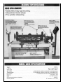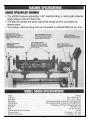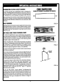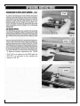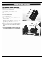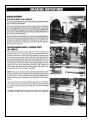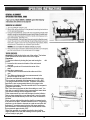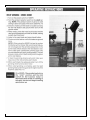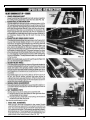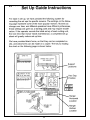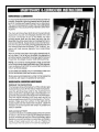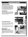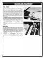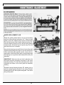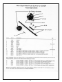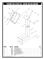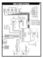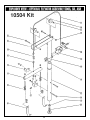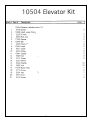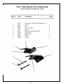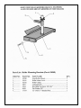
1
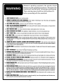
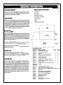
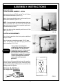
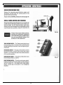
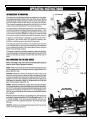
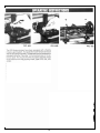
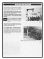
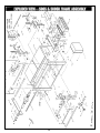
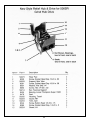
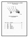
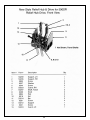
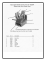
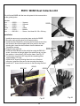
MODEL 500
MODULAR MOWER
SHARPENING SYSTEM
Patent No. 5,321,912
Please complete the following:
Serial #
Date Purchased
Purchased From
Phone #
Neary Technologies
1173 Benson Street
River Falls, WI 54022
1
Manual No. 50300 (3-01)
Thank you for choosing Neary Technologies as your supplier of sharpening equipment. Neary Technologies
machinery is for sharpening reel and rotary mower blades and bedknives. It is our goal to provide equipment
that makes your job easier. Please read the manual for information regarding safety, set up and proper operation of this equipment. In the future it may be necessary to order service parts for this machine. Please record
the serial number and purchase information on this page as ready reference when ordering parts.
Warranty Registration, please complete the warranty registration included with this manual and return it to
the factory. We use these records to advise you of additional information about this machine as well as for
tracking warranty information.
Model 500
The Model 500 is a modular design offered with several levels of features as well as different electrical voltages. This manual addresses the entire family of Models:
2
TABLE OF CONTENTS
ASSEMBLY .............................................................. Page 5 - 6
NEARY GRINDERS ................................................. Page 7 - 8
OPERATION ............................................................ Page 9 - 21
SET UP .................................................................... Page 22 - 24
MAINTENANCE & SERVICE ................................... Page 25 - 28
TROUBLE SHOOTING ........................................... Page 29 - 35
PARTS LISTS ........................................................ Page 36 - 58
3
WARNING
Whenever operating equipment, the operator should
always use safe operating procedures. Throughout the
manual you’ll see the Neary Technologies warning sign.
These warning signs should be strictly adhered to
before proceeding with the operations.
4
PACKING LIST
Part No. & Description
500S
500SR
09877 ....... Small Hex Key Set
1
1
09789 ....... Large Hex Key Set
1
1
50300 ....... Manual
1
1
50014 ....... Wrench for Wheel Hubs
1
1
50081 ....... Eccentric Pins for 55117
3
3
50505 ....... Front Roller Kit
1
1
50523 ....... Taper Checker
1
1
50541 ....... Shaft Drive Adapter, Male
1
1
50542 ....... Shaft Drive Adapter, Female
1
1
55117 ....... Drive Plate
1
1
55509 ....... Table Mount Diamond Dresser 1
1
09735 ....... Knob
1
Optional
05710 ....... Grinding Wheel, spare
05711 ....... Relief Grinding Wheel, spare
09816 ........ Mounting Rod for Jacobson Greensking 22-1/4”
10504 ........ Elevator
50129 ........ Ransomes Drive Adapter
50171 ........ John Deere Fairway Adapter
50176 ........ Toro Turf Pro 84 Adapter
50900 ........ Equipment Cover
55506 ........ Reel Mounting Kit
55528 ........ Enclosure
55577 ........ Dust Collection System
55903 ........ Lift Table
5
ASSEMBLY INSTRUCTIONS
MOUNT OPTIONAL
ELEVATOR WINCH ASSEMBLY -- #50104
Spray a dry lubricant or WD-40, onot the Top 4 to 5 inches
of the elevatro shaft base. (See FIG. 3)
Mount the pre-assembled elevator winch assembly onto
the elevator shaft base. (See FIG. 4)
NOTE: If you purchased the optional elevator winch assembly at another time, then mount the elevator shaft
base to the left side frome with the supplied angle brackets and hardware provided.
Mount the chain and bar assembly onto the end of the
cable. (See FIG. 4)
FIG. 3
ELECTRICAL REQUIREMENTS
The unit has be prewired at the factory and no additional
wiring is needed.
The unit requires a standard grounded 115V 20 amp
circuit for operation. Your outlet and plug should look
like the dawings in FIG. 5 & 6.
WARNING
Your grinder must always be
connected to a properly grounded
circuit. DO NOT run the unit on a
long extension cord. An improperly
grounded grinder can cause an
electrical shock and in turn serious
injurty to the operator. If necessary,
contact a qualified electricaian to
insure your unit is properly
grounded.
FIG. 4
Your unit is now fully assembled and ready for operation.
However, before operating your unit, review the following specifications pages and familiarize yourself with the
working parts of the grinder.
115 Volts 20 AMP Circuit
12 Guage Wire Mininmum
FIG. 6
6
7
8
OPERATING SECTION
PLEASE READ THE FOLLOWING
INFORMATION ON THIS PAGE
BEFORE PROCEEDING ON WITH
THE OPERATING SECTION.
Because of the unique modular design of the 500 Series grinders, the
operating instructions of the 500 and 500SR are combined together on the
following pages. This may be a little confusing to follow at first, but as you
upgrade from a 500S to 500SR, you will begin to appreciate why we have
combined instructions into one manual. You won’t have to start from scratch
and learn “new” equipment in a “new” operating manual. You will just come
back to your basic set of instructions and build on what you already have
learned.
The most important part of this manual is the next five pages. Basic spin
and relief grinding operations are very simple on Neary Technologies equipment. So the most important task at hand is to familiarize yourself with the
controls and switches on your model of grinder. You are encouraged to
turn on the controls and view its operation, and in no time you will be
grinding with ease!
Service and training are very important to us at Neary Technologies. Please
call with questions or comments. Thanks for buying our equipment and we
look forward to working with you in the years ahead.
9
10
A diamond dresser attachment No. 55509
(FIG. 25) is an option for the 500S and the
500 SR. It is mounted to the machine as
shown in FIG. 25.
11
12
13
14
15
16
17
Assembly: Install the foot to the end of the caliper. The bottom
of the foot should be flush with the end of the caliper.
Operation:
1. Zero the indicator by closing the jaws and turning the
dial
to zero.
2. Locate the foot across two blades of the reel toward
one end.
3. Extend the probe until it contacts the center of the
shaft.
4. Note the measurement.
5. Take the same measurement at the other end of the
reel.
6. The difference between the tow measurements is the
amount of taper in the reel.
Follow the manufacturer’s specifications for allowable taper.
Tor’s maximum allowable reel diameter taper is .040 - .060”.
This gauge measures from one side. Therefore, the diffence
between the two measuements taken by this gauge is the
difference in the radius. Take this number times 2 to compare to
a diameter specification.
Tip: There are many places to take the reading on a reel. You
may wish to mark the places where measurements were taken
so that later readings can be compared to them.
If tthe measurement you took with the taper checker indicates
that you have a tapered or cone shaped reel. Lower the grinding shaft (with the handwheel) on the end of the mower that is
smallest.
Once you have adjusted the grinding shaft for a tapered reel or
if the reel has no taper. Set both indicators to zero. The grinding
shaft can now be raised or lowered an equal amount within the
indicators 2” operating range by having the same reading on
both indicators or use the scribe lines on the handwheel. Each
line represents approximately .005”.
When this operation is complete the grinding wheel will be
aligned parallel to the reel shaft making it a true cylinder. Now
you are ready to spin grind.
18
FIG. 48
19
20
This page left intentionally blank for note taking purposes.
21
22
23
24
25
26
27
WHEEL REPLACEMENT S, SR
Raise the grinding wheel shaft to its top most position
and then lower the right end about 1/4”. Remove shaft
guard on the 500. Support the pivot arm and then back
the left infeed screw away from the bearing housing. Remove the bearing housing on SR, and the relief grinding
restraint shaft should be moved up and away from the
grind shaft as far as is feasible.
Now with the bearing removed lift the left end of the shaft
and slide the grinding wheel (spin or spin and relief) hubs
off the shaft. Using the spanner wrench, remove and replace wheel. Place wheel hubs back on the grinding shaft
and making sure to get them back between the drive yoke
assembly.
IMPORTANT: Make sure the spin hub is placed on the
shaft with the same orientation as shown on the frame
assembly drawing. The relief hub should have the same
orientation as shown on the relief grind hub assembly
drawing.
Reinstall bearing (bearing housing SR, making sure to
get the bearing housing located on the pins). Reinstall
restraint shaft on SR, then replace shaft guard. Then home
the grinding shaft.
28
29
30
31
32
33
34
35
36
50523 TAPER CHECKER
Parts List: 50523 Taper includes 50524 Caliper and 50525 Foot.
37
38
39
40
41
Item
No.
Part Part
No. Name
Qty
1 ........... 09441 .. Up - Down Decal .................................... 2
2 ........... 09001 .. Hex Jam Nut 1/2 - 13” ............................ 4
3 ........... 50116 .. Handwheel ............................................. 2
4 ........... 09492 .. Thrust Bearing ........................................ 2
5 ........... 50591 .. Cap Assembly ........................................ 2
6 ........... 09068 .. Spring Washer ....................................... 6
7 ........... 09023 .. Hex Nut Nylok 1/2 - 13” .......................... 2
8 ........... 50092 .. Vertical Adjustment Screw ..................... 2
9 ........... 09261 .. Socket Cap Screw 10 - 24 x 3/8” ............ 4
10 ......... 55294 .. Vertical Column ...................................... 2
11 ......... 09501 .. Socket BHCS 1/2 - 13 x 1” ..................... 2
12 ......... 09299 .. Socket BHCS 1/2 - 13 x 2-1/2 ................ 2
13 ......... 50095 .. Mount Block ........................................... 2
14 ......... 55336 .. Finger Pivot ............................................ 2
15 ......... 09221 .. Socket Set Screw 6- 32 x 1/8” ................ 2
16 ......... 55532 .. Tube, Scale Actuator RH, Threaded, for
.......................... “S & “SR ................................................. 1
............. 55533 .. Tube, Scale Actuator LH, Threaded, for
“S” & “SR” ................................................ 1
17 ......... 09526 .. Socket FHCS 3 x 0.5 x 6.0 mm .............. 6
18 ......... 55337 .. Gage Mount Plate .................................. 2
19 ......... 09294 .. Rollpin 1/8 x 1/2” .................................... 2
20 ......... 09707 .. Digital Scale ........................................... 2
21 ......... 09258 .. Scoket Cap Screw 8-32 x 3/8” ................ 4
22 ......... 09013 .. Hex Nut 1/2 - 13 .................................... 4
23 ......... 09064 .. Locking Washer 1/2” .............................. 4
24 ......... 55231 .. Dial Indicator Drive ................................. 2
25 ......... 09488 .. Dial Indicator 2” Drive ............................. 2
26 ......... 50155 .. Mounting Block ....................................... 2
27 ......... 09261 .. Socket Cap Screw 10 -24 x 3/8” ............. 4
28 ......... 09064 .. Locking Washer 1/2” .............................. 2
29 ......... 55295 .. Vertical Adjustment Shaft ....................... 2
31 ......... 50114 .. Pointer .................................................... 2
32 ......... 55226 .. Bracket Modified .................................... 2
33 ......... 09533 .. 10 -32 x 3/4” Socket HCS ....................... 2
42
43
44
Rear Roller Clamp 50254
45
3
12
46
47
48
49
50
51
52
53
54
55
56
57
55578 500SR Dust Collection Kit
This kit fits the 500SR with the two rail system for the traverse dirve
for the grinding hubs.
Includes:
One ............ 09818............... Vacuum
50253
Two ............ 50252............... Collector
One ............ 50253............... Tee
Three .......... 80035............... Clamp
One ............ 55243............... Bracket
One ............ B251201 .......... Screw - Hex Head 1/4 -20 x 3/4 long
Installation
80035
1. Install the vacuum at a convenient place under the 500SR.
2. Move the main grinding shaft to its lowest position.
3. Install the dust collectors by removing the two back screws from
the aluminum block that supports the drive yoke for the main
grinding hub. Insert the dust collector from the bottom and
reinstall the screws.
Screw to remove
4. Repeat for the relief hub.
and reinstall
5. Install the 55243 Bracket to the switch bar using the B251201
screw. It must be on the right side of the switch bar as you face
the machine. It should be 3-5/8”from the frame. See Fig. 97
6. Cut the hose, two pieces 28” long with the remaining piece
approximately 57” Long.
7. Install the 28” hoses by twisting them into one of the dust
collectors. Install the other end to the tee using the clamps.
8. Install the 57” hoses from the vacuum to the tee using the third
clamp.
B251201
Fig. 94
Fig. 95
55243
50252
Fig. 97
58
Fig. 96