1
Single Pump Dis-Assembly & Re-Assembly
Dis-Assemble Single Pump:
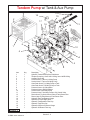
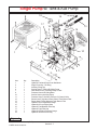
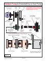
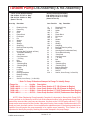
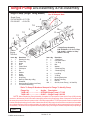
(For item numbers See Figure 17)
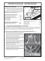
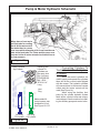
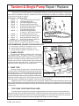
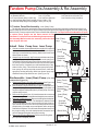
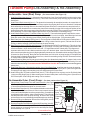
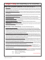
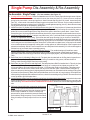
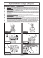
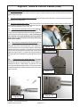
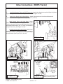
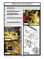
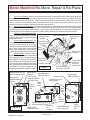
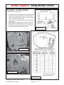
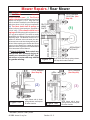
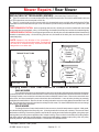
1. Clamp Single Pump in Vice with Jaw Protectors. (See Figure 15) Single pump can be clamped in vice or it can
be disassembled while on work bench
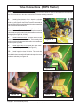
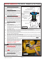
2. Remove Back Plate (Item 2). The backplate is mounted with
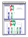
Single Pump Assembly
six hex head bolts (item 9), remove these six bolts. It will
require a small amount of force to free the backplate loose from
Pressure Port
pump housing. Use soft faced hammer, tap sides of backplate.
Suction
This will break the backplate loose from pump housing, do not
hit back plate with excessive force it will damage backplate
Port
and pump housing.
3. Remove O-Ring from Backplate. Remove the O-Ring Seal
Vice Jaw
123
(item 8) from backplate (item 2).
123
123
Protective
123
123
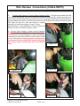
4. Remove Complete Piston Block Assembly (item 1) from Pump
Pads
Housing (item 4). Lift Piston Block asy upward and out of pump
housing, It will require you to remove pump from vice and dump
Bench Vice
Piston Block asy out. Catch the block with hand don't let it fall
out on floor or bench. DO NOT remove the spring snap Ring
(item 1K) from piston block assembly as spring (item 1H) has
Figure 18
compression on it, this compression will require relieving
before snap ring is removed, this can be done later.
5. Remove the Piston Assembly (item 19A) from the Piston Block (item 1D). The piston assembly will pull upward
and out of piston block.
6. Remove Spider (item 1B) and Pivot (item 1C) . The spider (item 1B) will be left lying on the piston block when
the piston assembly is removed. The Pivot (item 1C) will also be left on the piston block and can be removed.
7. Piston Block Dis-Assembly (item 1D). The Piston block assembly need not be dis-assembled unless the
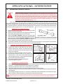
pins (item 19F) or the Spring (item 1H) is damaged. CAUTION ! The following procedure should be used if the
spring is to be removed from the piston block. The spring (item 19H) is highly compressed and the snap ring (item
1K) should NOT be removed without compressing the spring.
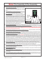
The following parts will be needed to dis-assemble the piston block
2 ea. 3/8" ID X 1-1/8" OD Flatwasher
1 ea. 3/8"-NC X 3-1/4" Bolt, Hex Head
1 ea. 3/8"-NC Hex Nut
Place one flatwashers over 3/8" X 3-1/4 bolt , place this through center of piston block. Place other flatwasher
over t bolt and let it rest on the three pins (item 1F). Screw the nut on and compress the spring inside piston block.
Use snap ring pliers and remove the internal snap ring (item 1K). Unscrew bolt, nut and two washers, this will
release pressure on spring (item 1H). Remove spring (item 1K), three pins (item 1F) and the pin keeper (item 1E).
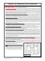
8. Remove Cam Plate Insert (item 7) from housing (item 4). The cam plate (item 7) should be lying inside the housing
(item 4). Reach into the housing and the cam plate (item 7) should pull out without much effort. In some cases
because of the oil creating suction it may require that housing be tilted up and cam plate dumped out of housing,
if this is the case catch the cam plate do not let it drop.
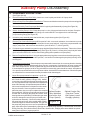
9. Remove Snap Ring (item 11). Using internal snap ring pliers remove internal snap ring (item 11) from front side
of housing (item 4).
10. Remove Input Seal (item 6) from housing (item 4). The input seal will be remove from the housing using a seal
puller. Use caution when removing the input seal so you don't scratch or damage the interior seal seat area.
11. Remove Seal Washer (item 10) which is located behind input seal. It may require to lift the housing and dump
the washer out.
12. Remove Driveshaft (item 3) from housing (item 4). The driveshaft must be pulled out of housing to the front side.
The driveshaft will have the retaining rings (item 12) and thrust race and bearing (item 5) still on it when it is pulled
out of housing.
13. Remove Snap Ring (item 12) and Thrust Race & Bearing (item 5) from drive shaft. Use Snap Ring Pliers to remove
the outer snap ring (item 12) from the end of the driveshaft. Slide the Trust Race & Bearing (item 5) from the
driveshaft. Remove the second snap ring (item 12) from the driveshaft using snap ring pliers.
Interstater - Service Manual (03/06)
© 2006 Alamo Industrial
Section 5 - 24