1
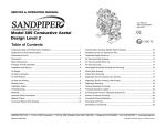
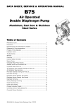
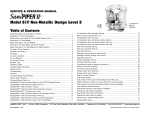
SERVICE & OPERATING MANUAL
Models 85627, 85628, 85629
1" Aluminum Air-Powered Diaphragm Pump
Table of Contents
U.S. Patent #
5,996,627
6,241,487
Other U.S. Patents
Applied for
CE
Engineering Data and Temperature Limitations .................................................. 1
Available Service and Conversion Kits .............................................................. 10
Performance Curve ............................................................................................... 2
Composite Repair Parts List .............................................................................. 11
Dimensions ........................................................................................................... 3
Air Distribution Valve Assembly Drawing and Parts List .................................... 12
Metric Dimensions ................................................................................................ 4
Air Distribution Valve Servicing .......................................................................... 13
Principle of Pump Operation ................................................................................ 5
Pilot Valve Assembly Drawing and Parts List ..................................................... 14
Installation and Start-Up ....................................................................................... 5
Pilot Valve Servicing ........................................................................................... 15
Air Supply ............................................................................................................. 5
Actuator Plunger Servicing ................................................................................. 15
Air Valve Lubrication ............................................................................................. 5
Diaphragm Service Drawing, with Overlay ........................................................ 16
Air Line Moisture .................................................................................................. 5
Diaphragm Service Drawing, Non-Overlay ....................................................... 16
Air Inlet and Priming ............................................................................................. 5
Diaphragm Servicing .......................................................................................... 17
Between Uses ...................................................................................................... 5
Overlay Diaphragm Servicing ............................................................................ 17
Installation Guide .................................................................................................. 6
Check Valve Servicing ........................................................................................ 18
Troubleshooting .................................................................................................... 7
Check Valve Drawing ......................................................................................... 18
Warranty ............................................................................................................... 7
Pumping Hazardous Liquids .............................................................................. 19
Recycling .............................................................................................................. 8
Converting Pump for Piping Exhaust Air ............................................................ 19
Important Safety Information ................................................................................ 8
Converted Exhaust Illustration ........................................................................... 19
Composite Repair Parts Drawing ...................................................................... 10
Section - B5
Page - 28
LINCOLN® • One Lincoln Way, St. Louis, MO 63120-1578 • Customer Service (314) 679-4300
520-357-000
12/01 Revision A
Form # 403161
Models 85627,
85628, 85629
CE
Air Inlet Side View
Air Exhaust Side View
1" Aluminum Air-Powered
Diaphragm Pump
U.S. Patent #
5,996,627
6,241,487
Other U.S. Patents
Applied for
ENGINEERING, PERFORMANCE
& CONSTRUCTION DATA
INTAKE/DISCHARGE PIPE SIZE
CAPACITY
AIR VALVE
SOLIDS-HANDLING
HEADS UP TO
DISPLACEMENT/STROKE
1" NPT(internal)
0 to 45 gallons per minute
(0 to 170 liters per minute)
No-lube, no-stall
design
Up to .25 in. (6mm)
125 psi or 289 ft. of water
(8.6 Kg/cm2 or 86 meters)
.11 Gallon / .42 liter
CAUTION! Operating temperature limitations are as follows:
Maximum*
Operating TTemperatures
emperatures
Minimum*
Optimum**
Buna General purpose, oil-resistant. Shows good solvent, oil, water and hydraulic fluid resistance.
Should not be used with highly polar solvents like acetone and MEK, ozone, chlorinated
hydrocarbons and nitro hyrdrocarbons.
190°F
88°C
-10°F
-23°C
50° to 140°F
10°C to 60°C
Neoprene All purpose. Resistant to vegetable oil. Generally not affected by moderate chemicals,
fats, greases and many oils and solvents. Generally attacked by strong oxidizing acids, ketones,
esters, nitro hydrocarbons and chlorinated aromatic hydrocarbons.
170°F
77°C
-10°F
-23°C
50° to 130°F
10°C to 54°C
Santoprene® Injection molded thermoplastic elastomer with no fabric layer. Long mechanical flex
life. Excellent abrasion resistance.
212°F
100°C
-10°F
-23°C
50° to 212°F
10°C to 100°C
V irgin PTFE Chemically inert, virtually impervious. Very few chemicals are known to react chemically with
PTFE: molten alkali metals, turbulent liquid or gaseous fluorine and a few fluoro-chemicals such as
chlorine trifluoride or oxygen difluoride which readily liberate free fluorine at elevated temperatures.
212°F
100°C
-35°F
-37°C
50°F to 212°F
10°C to 100°C
Polypropylene
150°F
65°C
-40°F
-40°C
Polyethylene
180°F
82°C
-40°F
-40°C
50°F to 140°F
10°C to 60°C
Hytrel®
190°F
-10°F
50°F to 140°F
88°C
-23°C
10°C to 60°C
Materials
520-357-000
12/01 Revision A
Page 1
BAR
PSI
Performance Curve
7
100
5(00)
100
6
25(00)
Head
3
60
60 PS
ar)
I (4.0
40
30(51)
.4 4 B
8 Bar
40 PS
I (2.72
35(00)
40(68)
Bar)
2
20
20 PSI (1.3
6
1
0
0
Bar) Air Inle
0
5
0
20
30
25
20
15
10
5
9.1
7.6
6
4.5
3
1.5
)
t Pressure
10
40
15
20
25
30
U.S. Gallons per minute
60
80
100
35
120
40
140
NPSHR
SI (5
5
METERS
80 P
FEET
80
4
10(17)
PSI
15(00)
(6.8
Bar
20(34)
)
45
160
Liters per minute
Capacity
520-357-000
12/01 Revision A
Page 2
Dimensions:
Dimensions in Inches
Dimensional Tolerance:±1/8"
DISCHARGE PORT
1" NPT
SUCTION PORT
1" NPT
STANDARD ENCAPSULATED MUFFLER
1" NPT EXHAUST PORT
FOR OPTIONAL MUFFLER
STYLES OR PIPING EXHAUST
AIR IN SUBMERGED
APPLICATIONS.
STANDARD PUMP SHOWN
WITH ENCAPSULATED MUFFLER
DIMENSION
Standard Pump
Mesh Muffler
A
10 3/8"
12 7/8"
AIR INLET
1/2" NPT
520-357-000
12/01 Revision A
Page 3
Metric Dimensions:
Dimensions in Millimeters
Dimensional Tolerance:± 3mm
DISCHARGE PORT
1" NPT
SUCTION PORT
1" NPT
STANDARD ENCAPSULATED MUFFLER
1" NPT EXHAUST PORT
FOR OPTIONAL MUFFLER
STANDARD PUMP SHOWN
STYLES OR PIPING EXHAUST
WITH ENCAPSULATED MUFFLER
AIR IN SUBMERGED
APPLICATIONS.
DIMENSION
Standard Pump
Mesh Muffler
520-357-000
12/01 Revision A
A
264mm
327mm
Page 4
PRINCIPLE OF PUMP OPERATION
This ball type check valve pump is
powered by compressed air and is a 1:1
ratio design. The inner side of one
diaphragm chamber is alternately
pressurized while simultaneously
exhausting the other inner chamber. This
causes the diaphragms, which are
connected by a common rod secured
by plates to the centers of the
diaphragms, to move in a reciprocating
action. (As one diaphragm performs the
discharge stroke the other diaphragm
is pulled to perform the suction stroke
in the opposite chamber.) Air pressure
is applied over the entire inner surface
of the diaphragm while liquid is
discharged from the opposite side of the
diaphragm. The diaphragm operates in
a balanced condition during the
discharge stroke which allows the pump
to be operated at discharge heads over
200 feet (61 meters) of water.
For maximum diaphragm life, keep
the pump as close to the liquid being
pumped as possible. Positive suction
head in excess of 10 feet of liquid (3.048
meters) may require a back pressure
regulating device to maximize
diaphragm life.
Alternate pressurizing and
exhausting of the diaphragm chamber
is performed by an externally mounted,
pilot operated, four way spool type air
distribution valve. When the spool shifts
to one end of the valve body, inlet
pressure is applied to one diaphragm
chamber and the other diaphragm
chamber exhausts. When the spool
520-357-000
12/01 Revision A
shifts to the opposite end of the valve
body, the pressure to the chambers is
reversed. The air distribution valve spool
is moved by a internal pilot valve which
alternately pressurizes one end of the
air distribution valve spool while
exhausting the other end. The pilot valve
is shifted at each end of the diaphragm
stroke when a actuator plunger is
contacted by the diaphragm plate. This
actuator plunger then pushes the end of
the pilot valve spool into position to
activate the air distribution valve.
The chambers are connected with
manifolds with a suction and discharge
check valve for each chamber,
maintaining flow in one direction through
the pump.
INSTALLATION AND START-UP
Locate the pump as close to the
product being pumped as possible. Keep
the suction line length and number of
fittings to a minimum. Do not reduce the
suction line diameter.
For installations of rigid piping, short
sections of flexible hose should be
installed between the pump and the
piping. The flexible hose reduces
vibration and strain to the pumping
system. A surge suppressor is
recommended to further reduce pulsation
in flow.
AIR SUPPLY
Air supply pressure cannot exceed
125 psi (8.6 bar). Connect the pump air
inlet to an air supply of sufficient capacity
and pressure required for desired
performance. When the air supply line
is solid piping, use a short length of
flexible hose not less than ½" (13mm)
in diameter between the pump and the
piping to reduce strain to the piping. The
weight of the air supply line, regulators
and filters must be supported by some
means other than the air inlet cap. Failure
to provide support for the piping may
result in damage to the pump. A pressure
regulating valve should be installed to
insure air supply pressure does not
exceed recommended limits.
AIR VALVE LUBRICATION
The air distribution valve and the pilot
valve are designed to operate WITHOUT
lubrication. This is the preferred mode of
operation. There may be instances of
personal preference or poor quality air
supplies when lubrication of the
compressed air supply is required. The
pump air system will operate with
properly lubricated compressed air
supply. Proper lubrication requires the
use of an air line lubricator set to deliver
one drop of SAE 10 non-detergent oil for
every 20 SCFM (9.4 liters/sec.) of air the
pump consumes at the point of operation.
Consult the pump’s published
Performance Curve to determine this.
from the compressed air supply and
alleviates the icing or freezing problems.
AIR INLET AND PRIMING
To start the pump, open the air valve
approximately ½ to ¾ turn. After the
pump primes, the air valve can be opened
to increase air flow as desired. If opening
the valve increases cycling rate, but does
not increase the rate of flow, cavitation
has occurred. The valve should be closed
slightly to obtain the most efficient air
flow to pump flow ratio.
BETWEEN USES
When the pump is used for materials
that tend to settle out or solidify when
not in motion, the pump should be flushed
after each use to prevent damage.
(Product remaining in the pump between
uses could dry out or settle out. This
could cause problems with the
diaphragms and check valves at restart.)
In freezing temperatures the pump must
be completely drained between uses in
all cases.
AIR LINE MOISTURE
Water in the compressed air supply
can create problems such as icing or
freezing of the exhaust air, causing the
pump to cycle erratically or stop
operating. Water in the air supply can
be reduced by using a point-of-use air
dryer to supplement the user’s air drying
equipment. This device removes water
Page 5
INSTALLATION GUIDE
Top Discharge Ball Valve Unit
1
1 Surge Suppressor
2
Filter/Regulator
3
Lubricator
CAUTION
The air exhaust should be
piped to an area for safe
disposition of the product
being pumped, in the event
of a diaphragm failure.
2
520-357-000
12/01 Revision A
3
Page 6
TROUBLESHOOTING
Possible Symptoms:
• Pump will not cycle.
• Pump cycles, but produces no flow.
• Pump cycles, but flow rate is
unsatisfactory.
• Pump cycle seems unbalanced.
• Pump cycle seems to produce
excessive vibration.
What to Check: Excessive suction lift
in system.
Corrective Action: For lifts exceeding
20 feet (6 meters), filling the pumping
chambers with liquid will prime the pump
in most cases.
What to Check: Excessive flooded
suction in system.
Corrective Action: For flooded
conditions exceeding 10 feet (3 meters)
of liquid, install a back pressure device.
What to Check: System head exceeds
air supply pressure.
Corrective Action: Increase the inlet air
pressure to the pump. Most diaphragm
pumps are designed for 1:1 pressure
ratio at zero flow.
What to Check: Air supply pressure or
volume exceeds system head.
Corrective Action: Decrease inlet air
pressure and volume to the pump as
calculated on the published
PERFORMANCE CURVE. Pump is
cavitating the fluid by fast cycling.
What to Check: Undersized suction
line.
520-357-000
12/01 Revision A
Corrective Action: Meet or exceed
pump connection recommendations
shown on the DIMENSIONAL
DRAWING.
What to Check: Restricted or
undersized air line.
Corrective Action: Install a larger air
line and connection. Refer to air inlet
recommendations shown in your pump’s
SERVICE MANUAL.
What to Check: Check ESADS, the
Externally Serviceable Air Distribution
System of the pump.
Corrective Action: Disassemble and
inspect the main air distribution valve,
pilot valve and pilot valve actuators. Refer
to the parts drawing and air valve section
of the SERVICE MANUAL. Check for
clogged discharge or closed valve before
reassembly.
What to Check: Rigid pipe connections
to pump.
Corrective Action: Install flexible
connectors and a surge suppressor.
What to Check: Blocked air exhaust
muffler.
Corrective Action: Remove muffler
screen, clean or de-ice and reinstall.
Refer to the Air Exhaust section of your
pump SERVICE MANUAL.
What to Check: Pumped fluid in air
exhaust muffler.
Corrective Action: Disassemble pump
chambers. Inspect for diaphragm rupture
or loose diaphragm plate assembly. Refer
to the Diaphragm Replacement section
of your pump SERVICE MANUAL.
for disassembly instructions.
What to Check: Suction side air
leakage or air in product.
Corrective Action: Visually inspect all
suction side gaskets and pipe
connections.
What to Check: Entrained air or vapor
lock in one or both pumping chambers.
Corrective Action: Purge chambers
through tapped chamber vent plugs.
PURGING THE CHAMBERS OF AIR
CAN BE DANGEROUS! Contact the
Customer Service Department before
performing this procedure. Any model
with top-ported discharge will reduce or
eliminate problems with entrained air.
If your pump continues to perform
below your expectations, contact your
local Distributor or factory Customer
Service Department for a service
evaluation.
What to Check: Obstructed check
valve.
Corrective Action: Disassemble the wet
end of the pump and manually dislodge
obstruction in the check valve pocket.
Refer to the Check Valve section of the
pump SERVICE MANUAL for
disassembly instructions.
What to Check: Worn or misaligned
check valve or check valve seat.
Corrective Action: Inspect check valves
and seats for wear and proper seating.
Replace if necessary. Refer to Check
Valve section of the pump SERVICE
MANUAL for disassembly instructions.
Warranty
This pump is warranted for a period
of five years against defective material
and workmanship.
What to Check: Blocked suction line.
Corrective Action: Remove or flush
obstruction. Check and clear all suction
screens and strainers.
What to Check: Blocked discharge line.
Corrective Action: Check for
obstruction or closed discharge line
valves.
What to Check: Blocked pumping
chamber.
Corrective Action: Disassemble and
inspect the wetted chambers of the
pump. Remove or flush any obstructions.
Refer to the pump SERVICE MANUAL
Page 7
RECYCLING
Many components of LINCOLN
AODD pumps are made of recyclable
materials (see chart on page 10 for
material specifications). We encourage
pump users to recycle worn out parts
and pumps whenever possible, after any
hazardous pumped fluids are thoroughly
flushed.
IMPORTANT SAFETY
INFORMATION
IMPORTANT
Read these safety warnings
and instructions in this
manual completely, before
installation and start-up
of the pump. It is the
responsibility of the purchaser to retain this
manual for reference. Failure to comply with
the recommendations stated in this manual will
damage the pump, and void factory warranty.
WARNING
Take action to prevent
static sparking. Fire or
explosion can result,
especially when handling
flammable liquids. The
pump, piping, valves, containers or other
miscellaneous equipment must be grounded.
WARNING
This pump is pressurized
internally with air pressure
during operation. Always
make certain that all bolting
is in good condition and that
all of the correct bolting is reinstalled during
assembly.
CAUTION
Before pump operation,
inspect all gasketed
fasteners for looseness
caused by gasket creep.
Re-torque loose fasteners
to prevent leakage. Follow recommended
torques stated in this manual.
WARNING
When used for toxic or
aggressive fluids, the pump
should always be flushed
clean prior to disassembly.
WARNING
WARNING
Before maintenance or
repair, shut off the compressed air line, bleed the
pressure, and disconnect
the air line from the pump.
The discharge line may be pressurized and
must be bled of its pressure.
WARNING
In the event of diaphragm
rupture, pumped material
may enter the air end of the
pump, and be discharged
into the atmosphere. If
pumping a product which is hazardous or toxic,
the air exhaust must be piped to an appropriate
area for safe disposition.
520-357-000
12/01 Revision A
Before doing any maintenance on the pump, be
certain all pressure is
completely vented from the
pump, suction, discharge,
piping, and all other openings and connections.
Be certain the air supply is locked out or made
non-operational, so that it cannot be started while
work is being done on the pump. Be certain that
approved eye protection and protective clothing
are worn all times in the vicinity of the pump.
Failure to follow these recommendations may
result in serious injury or death.
WARNING
Airborne particles and loud
noise hazards.
Wear ear and eye protection.
Page 8
520-357-000
12/01 Revision A
Page 9
Composite Repair Parts Drawing
AVAILABLE SERVICE AND CONVERSION KITS
271811
271813
271812
520-357-000
WET END KIT
Buna Diaphragms, Buna Balls, and
UHMW Polyethylene Seats.
WET END KIT
Hytrel Diaphragms, Hytrel Balls and
UHMW Polyethylene Seats.
WET END KIT
Neoprene Diaphragms, PTFE
Overlay Diaphragms, PTFE Balls and
PTFE Seats.
12/01 Revision A
Page 10
Composite Repair Parts List
ITEM
DESCRIPTION
QTY
MODEL 85627
MODEL 85628
MODEL 85629
1
2
3
4
5
6
7
8
9
10
11
12
13
14
15
16
17
18
19
20
21
23
24
25
26
27
28
29
30
Air Valve Assembly
Ball, Check
Bearing, Sleeve
Pilot Valve Assembly
Bracket, Intermediate
Bumper
Bushing, Plunger
Cap, Air Inlet
Capscrew, Hex Head 5/16-18UNC x .88
Capscrew, Hex Head 5/16-18 x 1.25
Capscrew, Hex Head 5/16-18UNC x 1.75
Capscrew, Socket Head 3/8-16UNC x 2.50
Chamber, Outer
Diaphragm
Diaphragm, Overlay
Gasket, Air Valve
Gasket, Pilot Valve
Gasket, Air Inlet
Manifold, Suction
Manifold, Discharge
O-Ring
Plate, Inner Diaphragm
Plate, Outer Diaphragm
Plunger, Actuator
Ring, Retaining
Rod, Diaphragm
Seal, U-Cup
Seat, Check Valve
Washer, Flat
1
4
2
1
1
2
2
1
16
16
4
4
2
2
2
1
1
1
1
1
2
2
2
2
2
1
2
4
4
271773
271814
240720
271782
271817
240727
252901
271818
271819
240731
271820
271821
271822
240983
271773
271815
240720
271782
271817
240727
252901
271818
271819
240731
271820
271821
271822
240873
240749
271795
271796
271797
271823
271824
240655
240729
240728
271825
240717
271826
240721
271827
271810
271773
271816
240720
271782
271817
240727
252901
271818
271819
240731
271820
271821
271822
240730
520-357-000
12/01 Revision A
271795
271796
271797
271823
271824
240655
240729
240728
271825
240717
271826
240721
271827
271810
271795
271796
271797
271823
271824
240655
240729
240728
271825
240717
271826
240721
271827
271810
Page 11
Air Valve Assembly Drawing, Parts List
1-J
1-H
1-G
1-D
1-G
1-E
1-C
1-F
1-A
1-A
ITEM
1
1-A
1-B
1-C
1-D
1-E
1-F
1-G
1-H
1-J
AIR VALVE ASSEMBLY PARTS LIST
PART NUMBER
DESCRIPTION
271773
Air Valve Assembly
271774
Sleeve and Spool Set
271775
Body, Air Valve
271776
Bumper
271777
Cap, Muffler
271778
Cap, End
271779
Muffler
271780
O-Ring
271781
Ring, Retaining
240932
Screw, Self-tapping
QTY
1
1
1
2
1
2
1
8
2
4
1-B
1-C
1-E
1-G
1-H
520-357-000
12/01 Revision A
Page 12
AIR DISTRIBUTION VALVE
SERVICING
To service the air valve first shut off
the compressed air, bleed pressure from
the pump, and disconnect the air supply
line from the pump.
STEP #1: See COMPOSITE REPAIR
PARTS DRAWING.
Using a 5/16" Allen wrench, remove
the four hex socket capscrews (item 12)
and four flat washers (item 30). Remove
the air valve assembly from the pump.
Remove and inspect gasket (item 16)
for cracks or damage. Replace gasket if
needed.
STEP #2: Disassembly of the air
valve.
To access the internal air valve
components first remove the two retaining
rings (item 1-H) from each end of the air
valve assembly using clip ring pliers.
Next remove the two end caps (item
1-E). Inspect the o-ring (item 1-G) for cuts
or wear. Replace the o-rings if necessary.
Remove the spool (part of item 1-A)
from the sleeve. Be careful not to scratch
or damage the outer diameter of the
spool. Wipe spool with a soft cloth and
inspect for scratches or wear.
520-357-000
12/01 Revision A
Inspect the inner diameter of the
sleeve (part of item 1-A) for dirt,
scratches, or other contaminants. Remove
the sleeve if needed and replace with a
new sleeve and spool set (item 1-A).
STEP #3: Reassembly of the air valve.
Install one end cap (item 1-E) with
an o-ring (item 1-G) into one end of the
air valve body (item 1-B). Install one
retaining ring (item 1-H) into the groove
on the same end.
Remove the new sleeve an spool set
(item 1-A) from the plastic bag. Carefully
remove the spool from the sleeve. Install
the six o-rings (item 1-G) into the six
grooves on the sleeve. Apply a light
coating of grease to the o-rings before
installing the sleeve into the valve body
(item 1-B), align the slots in the sleeve
with the slots in the valve body. Insert
the spool into the sleeve. Be careful not
to scratch or damage the spool during
installation. Push the spool in until it
touches the bumper on the opposite end.
Install the remaining end cap with oring and retaining ring.
Fasten the air valve assembly (item
1) and gasket (item 16) to the pump.
Connect the compressed air line to
the pump. The pump is now ready for
operation.
IMPORTANT
Read these instructions
completely, before installation and start-up. It
is the responsibility of
the purchaser to retain
this manual for reference. Failure to
comply with the recommendations stated
in this manual will damage the pump, and
void factory warranty.
Page 13
Pilot Valve Assembly Drawing, Parts List
PILOT VALVE ASSEMBLY PARTS LIST
ITEM
4
4-A
4-B
4-C
4-D
4-E
4-F
520-357-000
12/01 Revision A
PART NUMBER
271782
271783
271784
252935
252936
252937
252938
DESCRIPTION
Pilot Valve Assembly
Body, Pilot Valve
Bushing
Ring, Retaining
Spacer
Spool, Pilot
Wiper
QTY
1
1
2
2
5
1
6
Page 14
PILOT VALVE SERVICING
To service the pilot valve first shut off
the compressed air supply, bleed the
pressure from the pump, and disconnect
the air supply line from the pump.
Step #1: See PUMP ASSEMBLY
DRAWING.
Using a ½" wrench or socket,
remove the four capscrews (items 11).
Remove the air inlet cap (item 8) and
air inlet gasket (item 18). The pilot valve
assembly (item 4) can now be removed
for inspection or service.
Step #2: Disassembly of the pilot
valve.
Remove the pilot valve spool (item
4-E). Wipe clean, and inspect for dirt,
scratches or wear. Replace the spool if
necessary.
Remove the two retaining rings
(items 4-C) from each end of the pilot
valve body.
Remove the two pilot valve bushings
(items 4-B), five spacers (items 4-D),
and six spool wipers (items 4-F) by
pushing gently from other end of the
pilot valve body. Inspect the wipers for
cuts and/or wear. Replace any wipers
as necessary.
Step #3: Re-assembly of the pilot
valve.
First install a retaining ring to one
end of the pilot valve. Install one bushing
making sure the step side faces toward
the wiper. Apply a light coating of grease
to the outside diameter of each wiper.
520-357-000
12/01 Revision A
Next, gently push in the wipers and
spacers until they are against the
installed retaining ring and bushing in
the opposite end of the pilot valve body.
Install the remaining bushing making
sure the step side faces the wiper. Install
the remaining retaining ring.
Apply a light coating of grease to the
inner diameter of each wiper. Also apply
a light coating of grease to the outer
diameter of the pilot valve spool and
gently push the spool through each wiper.
Step #4: Inspect the actuator
plungers.
See ILLUSTRATION AT RIGHT.
The actuator plungers (items 25) can
be reached through the pilot valve cavity
in the intermediate assembly (item 5).
Remove the plungers (item 25) from
the bushings (item 7) in each end of the
cavity. Inspect the installed o-ring (items
21) for cuts and/or wear. Replace the orings if necessary. Apply a light coating
of grease to each o-ring and re-install
the plungers in to the bushings. Push
the plungers in as far as they will go.
To remove the bushings (item 7), first
remove the retaining rings (item 26) by
using a flat screwdriver. NOTE: It is
recommended that new retaining rings
be installed.
Step #5: Re-install the pilot valve
assembly into the intermediate assembly.
Be careful to align the ends of the
stem between the plungers when
inserting the stem of the pilot valve into
the cavity of the intermediate.
Re-install the gasket (item 18), air
inlet cap (item 8) and capscrews
(item 11).
Connect the air supply to the pump.
The pump is now ready for operation.
IMPORTANT
Read these instructions
completely, before installation and start-up. It
is the responsibility of
the purchaser to retain
this manual for reference. Failure to
comply with the recommendations stated
in this manual will damage the pump, and
void factory warranty.
ACTUATOR PLUNGER
SERVICING
25
21
7
26
5
Page 15
Diaphragm Service Drawing,
with Overlay
520-357-000
12/01 Revision A
Diaphragm Service Drawing,
Non-Overlay
Page 16
DIAPHRAGM SERVICING
To service the diaphragms first shut off
the suction, then shut off the discharge
lines to the pump. Shut off the compressed air supply, bleed the pressure
from the pump and disconnect the air
supply line from the pump. Drain any
remaining liquid from the pump.
Step #1: See the pump assembly
drawing and the diaphragm servicing illustration.
Using a 1/2” wrench or socket, remove the 16 capscrews (item 9) that fasten the manifolds (items 19 & 20) to the
outer chambers (item 13).
Step #2: Removing outer chambers.
Using a 1/2” wrench or socket,
remove the 16 capscrews (item 10), that
fasten the outer chambers (item 13),
diaphragms (item 14) and intermediate
(item 5) together.
Step #3: Removing the diaphragms
and diaphragm plates.
Use a 7/8” wrench or six point
socket to remove the outer diaphragm
plate assemblies (item 24), diaphragms
(item 14) and inner diaphragm plates
(item 23) from the diaphragm rod (item
27) by turning counterclockwise. Inspect
the diaphragm for cuts, punctures, abrasive wear or chemical attack. Replace
the diaphragms if necessary. DO NOT
USE A WRENCH ON THE DIAPHRAGM
ROD. FLAWS ON THE SURFACE MAY
DAMAGE BEARINGS AND SEALS.
Step #4:
520-357-000
diaphragm and diaphragm plates to the
diaphragm rod.
Push the threaded stud of one outer
diaphragm plate assembly through the
center of one diaphragm and through one
inner diaphragm plate. Install the diaphragm with the natural bulge facing
away from the diaphragm rod and make
sure the radius on the inner diaphragm
plate is towards the diaphragm, as indicated on the diaphragm servicing illustration. Thread the assembly onto the
diaphragm rod, leaving loose.
Step #5: Installing the diaphragm
and rod assembly to the pump.
Make sure the bumper (item 6) is
installed over the diaphragm rod. Insert
rod into pump.
On the opposite side of the pump,
pull the diaphragm rod out as far as possible. Make sure the second bumper is
installed over the diaphragm rod.
Push the threaded stud of the other
outer diaphragm plate assembly through
the center of the other diaphragm and
through the other inner diaphragm plate.
Make sure the radius on the inner diaphragm plate is towards the diaphragm.
Thread the assembly onto the diaphragm
rod. Use a 7/8” wrench or socket to hold
one outer diaphragm plate. Then, use a
torque wrench to tighten the other outer
diaphragm plate to the diaphragm rod to
500 in. lbs. (56.5 Newton meters).
Align one diaphragm with the intermediate and install the outer chamber
to the pump using the 8 capscrews.
Tighten the opposite diaphragm plate
until the holes in the diaphragm align with
the holes in the intermediate. Then, install the other outer chamber using the
8 capscrews.
Step #6: Reinstall the manifolds
to the pump using the 16 capscrews.
The pump is now ready to be reinstalled, connected and returned to
operation.
IMPORTANT
Read these instructions
completely, before installation and start-up. It
is the responsibility of
the purchaser to retain
this manual for reference. Failure to
comply with the recommendations stated
in this manual will damage the pump, and
void factory warranty.
OVERLAY DIAPHRAGM SERVICING
The overlay diaphragm (item 15)
is designed to fit over the exterior of the
standard diaphragm (item 14).
Follow the same procedures
described for the standard diaphragm
for removal and installation, except
tighten the outer diaphragm plate
assembly, diaphragms and inner diaphragm plate to the diaphragm rod to 500
in. lbs. (56.5 Newton meters).
Assembling the
12/01 Revision A
Page 17
CHECK VALVE SERVICING
Before servicing the check valve
components, first shut off the suction line
and then the discharge line to the pump.
Next, shut off the compressed air supply,
bleed air pressure from the pump, and
disconnect the air supply line from the
pump. Drain any remaining fluid from the
pump. The pump can now be removed
for service.
To access the check valve
components, remove the manifold
(item 20 or item 19 not shown). Use a
1
/2" wrench or socket to remove the
fasteners. Once the manifold is removed,
the check valve components can be
seen.
Inspect the check balls (items 2) for
wear, abrasion, or cuts on the spherical
surface. The check valve seats (item 29)
should be inspected for cuts, abrasive
wear, or embedded material on the
surfaces of both the external and internal
chambers. The spherical surface of the
check balls must seat flush to the
surface of the check valve seats for the
pump to operate to peak efficiency.
Replace any worn or damaged parts as
necessary.
Re-assemble the check valve
components. The seat should fit into the
counter bore of the outer chamber.
The pump can now be reassembled,
reconnected and returned to operation.
520-357-000
12/01 Revision A
Check Valve Drawing
20
9
2
29
Page 18
PUMPING HAZARDOUS LIQUIDS
When a diaphragm fails, the pumped
liquid or fumes enter the air end of the
pump. Fumes are exhausted into the
surrounding environment. When pumping
hazardous or toxic materials, the
exhaust air must be piped to an
appropriate area for safe disposal. See
illustration #1 at right.
This pump can be submerged if the
pump materials of construction are
compatible with the liquid being pumped.
The air exhaust must be piped above the
liquid level. See illustration #2 at right.
Piping used for the air exhaust must not
be smaller than 1" (2.54 cm) diameter.
Reducing the pipe size will restrict air
flow and reduce pump performance.
When the pumped product source is at
a higher level than the pump (flooded
suction condition), pipe the exhaust
higher than the product source to prevent
siphoning spills. See illustration #3 at
right.
CONVERTING THE PUMP FOR
PIPING THE EXHAUST AIR
The following steps are necessary to
convert the pump to pipe the exhaust air
away from the pump.
Use a #8 Torx or flat screwdriver
to remove the four self-tapping screws
(item 1-J).
Remove the muffler cap and muffler
(items 1-D and 1-F). The air distribution
valve body (item 1-B) has 1" NPT threads
for installation of alternate mesh or sound
dampening mufflers or piped exhaust.
IMPORTANT INSTALLATION
NOTE: The manufacturer recommends
installing a flexible hose or connection
between the pump and any rigid
plumbing. This reduces stresses on the
molded plastic threads of the air exhaust
port. Failure to do so may result in
damage to the air distribution valve body.
Any piping or hose connected to the
pump’s air exhaust port must be
physically supported. Failure to support
these connections could also result in
damage to the air distribution valve body.
CONVERTED EXHAUST ILLUSTRATION
PUMP INSTALLATION AREA
SAFE AIR
EXHAUST
DISPOSAL
AREA
1" DIAMETER AIR
EXHAUST PIPING
MUFFLER
Illustration #1
MUFFLER
LIQUID
LEVEL
1" DIAMETER AIR
EXHAUST PIPING
SUCTION
LINE
Illustration #2
MUFFLER
LIQUID
LEVEL
1" DIAMETER AIR
EXHAUST PIPING
SUCTION
LINE
Illustration #3
520-357-000
12/01 Revision A
Page 19