1
7
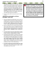
INTERMEDIATE (OVER-BOTTOM) PRESSURE TEST
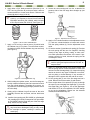
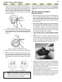
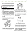
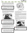
1. Depress the second stage purge to determine once
again that the system is not pressurized. While holding
the hex nut (27) of the second stage secure with a 13/16”
open-end wrench, apply an 11/16” open-end wrench to
the female fitting of the IP hose. Turn the fitting counterclockwise to loosen and remove the hose from the
second stage.
2. Connect the intermediate pressure test gauge to the female fitting of the IP hose, and tighten the hose fitting by
hand until finger tight.
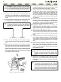
3. While holding the IP test gauge positioned facing away
from you, pressurize the system by slowing turning the
H.A.B.D. valve to the “ON” position. Check the H.A.B.D.
pressure gauge assembly once again to ensure that it
indicates the cylinder is filled with at least 2,500 psi.
4. Note the intermediate (over-bottom) pressure indicated
by the test gauge, and briefly open and shut the bleed
valve of the test gauge to ensure that lockup is achieved
without “creeping” or fluctuating back and forth.
5. If the intermediate pressure “creeps” up or otherwise fluctuates after cycling the regulator, wait for it to stabilize (if
possible) before noting the final intermediate pressure.
NOTE: Correct intermediate pressure for the
H.A.B.D. is 140 ± 5 psi, with an inlet pressure between 2,500 - 3,000 psi.
6. P
artially open the bleed valve of the test gauge to empty
the H.A.B.D. cylinder very slowly. DO NOT fully open the
test gauge bleed valve to empty the cylinder, as this may
cause condensation of moisture to form inside the first
stage and hose, as well as the cylinder itself. If the cylinder of valve becomes cold to the touch while preforming
this step, the air has been relieved too rapidly.
CAUTION: Use only a plastic or brass O-ring removal tool (PN 944022) when removing O-rings
to prevent damage to the sealing surface. Even
a small scratch across an O-ring sealing surface
could result in leakage. Once an O-ring sealing
surface has been damaged, the part must be replaced with new. DO NOT use a dental pick, or any
other steel instrument.
FIRST STAGE DISASSEMBLY
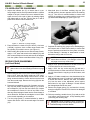
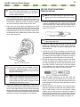
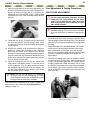
1. A
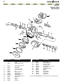
pply an 11/16” open-end wrench to the flats of the pressure gauge assembly (14), and turn the gauge counterclockwise to loosen and remove from the first stage. Remove and discard the O-ring (13), and set the pressure
gauge assembly aside.
2. Apply a 1/2” open-end wrench to the safety plug (11c),
and turn counterclockwise to loosen and remove. Discard the safety plug, and do not attempt to reuse.
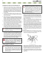
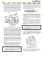
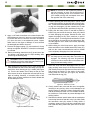
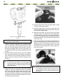
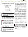
3. Check to ensure that the H.A.B.D. valve is closed to the
“OFF” position. While holding a shop rag over the first
stage to cover the open HP port of the safety plug, direct
low pressure air (120-140 psi) through the open HP port
to dislodge the safety disc (11b) and gasket (11a) of the
safety burst disc assembly (11). (See Figure 4). Remove
the shop rag to allow the safety disc and gasket to fall
out of the first stage body. Discard these items and do
not reuse.
3a.Alternate method: Pierce the safety disc with the pointed o-ring tool. Remove disc, and discard gasket. Use
caution not to damage the seating surface.
WARNING: Failure to completely empty the
H.A.B.D. of air prior to performing any disassembly may cause the sudden separation of
components or ejection of parts, and may result in serious personal injury.
Disassembly Procedures
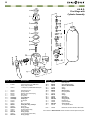
NOTE: Before performing any disassembly, refer to
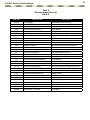
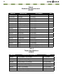
the schematic drawing, which references all mandatory replacement parts. These parts should be
replaced with new, and must not be reused under
any circumstances - regardless of the age of the
regulator or how much use it has received since it
was last serviced.
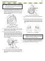
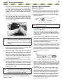
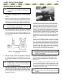
4. A
pply external circlip pliers (PN 111100) to the retaining
ring (20) which holds the IP hose (19) in place. Spread
the retaining ring and remove from the IP port swivel (17).
Discard the retaining ring and do not attempt to reuse.
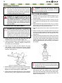
5. F
irmly grasp the banjo fitting of the IP hose and pull
it straight off the port swivel. Set the hose and second
stage aside.