1
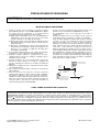
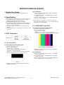
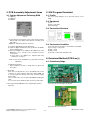
Internal Use Only
website:http://biz.LGservice.com
PLASMA TV
MANUAL DE SERVICIO
CHASIS : PP81A
MODELO : 42PG20R
42PG20R-MA
ATENCIÓN
Antes de dar servicio al chasis, lea las PRECAUCIONES DE SEGURIDAD
en este manual.
INPUT
MENU
ENTER
VOL
CH
CONTENIDO
CONTENIDO ............................................................................................................................ 2
PRECAUCIONES DE SEGURIDAD .........................................................................................3
INSTRUCCIONES DE AJUSTE ...............................................................................................4
DIAGRAMA EN BLOQUE ......................................................................................................12
VISTA EN DESPIECE .............................................................................................................14
LISTA DE VISTA EN DESPIECE.............................................................................................15
DIAGRAMA ESQUEMÁTICO......................................................................................................
TABLERO DE CIRCUITO IMPRESO ..........................................................................................
Copyright©2007 LG Electronics. Inc. All right reserved.
Only for training and service purposes
- 2 -
LGE Internal Use Only
PRECAUCIONES DE SEGURIDAD
ADVERTENCIA: Antes de dar servicio a este chasis, lea "PRECAUCIONES RESPECTO A RADIACION POR RAYOS X",
"INSTRUCCIONES DE SEGURIDAD" y "AVISO SOBRE SEGURIDAD DE PRODUCTOS"
INSTRUCCIONES DE SEGURIDAD
1. Cuando el receptor está en operación, se producen voltajes
potencialmente tan altos como 25,000-29,000 voltios. Operar
el receptor fuera de su gabinete o con la tapa trasera
removida puede causar peligro de choque eléctrico.
(1) Nadie debe intentar dar servicio si no está debidamente
familiarizado con las precauciones que son necesarias
cuando se trabaja con un equipo de alto voltaje.
(2) Siempre descargue el ánodo del tubo de la imagen a tierra
para evitar el riesgo de choque eléctrico antes de remover
la tapa del ánodo.
(3) Descargue completamente el alto potencial del tubo de
imagen antes de manipularlo. El tubo de la imagen es de
alto vacío y, si se rompe, los fragmentos de vidrio salen
despedidos violentamente.
2. Si se quemara algún fusible de este receptor de televisión,
reemplácelo con otro especificado en la lista de partes.
3. Cuando reemplace tableros o plaquetas de circuitos,
cuidadosamente enrolle sus alambres alrededor de las
terminales antes de soldar.
4. Cuando reemplace un resistencia de vataje (resistor de
película de óxido metálico) en el Tablero o Plaqueta de
circuitos, mantenga la resistencia a un mínimo de 10mm de
distancia.
5. Mantenga los alambres lejos de componentes de alto voltaje
o de alta temperatura.
6. Este receptor de televisión debe conectarse a una fuente de
100 a 240 V AC.
7. Antes de devolver este aparato al cliente, haga una
verificación de fuga de corriente sobre las partes metálicas
del gabinete expuestas, tales como antenas, terminales,
cabezas de tornillos, tapas de metal, palancas de control etc.,
para estar seguro de que el equipo funciona sin peligro de
choque eléctrico. Enchufe el cordón directamente al
tomacorriente de la línea de AC 100-240V.
No utilice una línea aislada de transformador durante esta
verificación. Use un voltímetro de 1000 Ohmios por voltio
de sensibilidad o más, en la forma que se describe a
continuación.
Cuando la unidad está ya conectada a la AC, pulse el
conmutador primero poniéndolo en "ON" (encendiendo) y
luego en "OFF" (apagando), mida desde un punto de tierra
conocido, tal como una (cañería de metal, una manija
metálica, una tubería etc.) a todas las partes metálicas
expuestas del receptor de televisión (antenas, manijas de
metal, gabinetes de metal, cubiertas de metal, palancas de
control etc.,) especialmente cualquiera de las partes
metálicas expuestas que puedan ofrecer un camino hacia el
chasis. Ninguna medición de corriente eléctrica debe exceder
de 0.5 miliamperios. Repita la prueba cambiando la posición
del enchufe en el tomacorriente. Cualquier medición que no
esté dentro de los límites especificados aquí representan un
riesgo potencial de choque eléctrico que debe ser eliminado
antes de devolver el equipo al cliente.
La lectura SHOULD
no debe
(READING
exceder
0.5mA
NOT BEde
ABOVE
0.5mA)
LEAKAGE
Probador
CURRENT
de fuga de
corriente
TESTER
Aparato
DEVICE
bajo
UNDER
TEST
examen
+Pruebe
todas
TEST
ALL
METAL
lasEXPOSED
superficies
SURFACES
metálicas
2-WIRE CORD
Tambien pruebe cón
ALSO
TEST WITH
los enchufes
al reves
PLUG REVERSED
(utilizando
adaptador
(USING
AC ADAPTER
en caso
PLUG
ASnecesario)
REQUIRED)
Tierra
EARTH
suelo
GROUND
AVISO SOBRE SEGURIDAD DE PRODUCTOS
Muchas de las partes, electricas y mecánicas en este chasis tienen caracteristicas relacionadas con la seguridad. Estas
caracteristicas frecuentemente pasan desapercibidas en las inspecciones visuales y la proteccion que proporcionan contra la
RADIACION DE RAYOS-X no siempre necesariamente se obtiene al mismo grado cuando se reemplazan piezas o componentes
diseñados para voltajes o vatajes mayores, etc. Las piezas que tienen estas caracteristicas de seguridad se identifican por la
marca
impresa sobre el diagrama esquematico. Antes de reemplazar alguno de esos componente, lea cuidadosamente la
lista de este manual. El uso de partes de reemplazo que no tengan las mismas caracteristicas de seguridad, como se especifica
en la lista de partes, puede crear Radiacion de Rayos-X.
Copyright©2007 LG Electronics. Inc. All right reserved.
Only for training and service purposes
- 3 -
LGE Internal Use Only
INSTRUCCIONES DE AJUSTE
(2) Confirmation
1. Application Range
1) We confirm whether “0xB6(RGB)” address of EEPROM
“0xA2” is “0xAA” or not.
2) If “0xB6(RGB)” address of EEPROM “0xB2” isn’t “0xAA”,
we adjust once more
3) We can confirm the ADC values from “0xB0~0xB5(RGB)”
addresses in a page “0xA2”
This spec. sheet is applied to all of the PP81A Chassis.
2. Specification
(1) Because this is not a hot chassis, it is not necessary to use
an isolation transformer. However, the use of isolation
transformer will help protect test instrument.
(2) Adjustment must be done in the correct order.
(3) The adjustment must be performed in the circumstance of
25±5cC of temperature and 65±10% of relative humidity if
there is no specific designation.
(4) The input voltage of the receiver must keep 100~240V,
50/60Hz.
(5) Before adjustment, execute Heat-Run for 30 minutes at RF
no signal.
[ Manual ADC process using Service Remocon. After enter
Service Mode by pushing “ADJ” key, execute “ADC Adjust” by
pushing “G” key at “Adjust-RGB”.
3-2. COMPONENT input ADC
(1) Component Gain/Offset Adjustment
1) Convert to Component in Input-source
2) Signal equipment displays
Impress Resolution 720P
MODEL : 216 in Pattern Generator(720P Mode)
PATTERN : 33 in Pattern Generator( MSPG-925 SERISE)
3. ADC calibration
3-1. PC input ADC
(1) Auto RGB Gain/Offset Adjustment
1) Convert to PC in Input-source
2) Signal equipment displays
Output Voltage : 700 mVp-p
Impress Resolution XGA (1024 x 768 @ 60Hz)
Model : 60 in Pattern Generator
Pattern : 54 in Pattern Generator (MSPG-925 SERISE)
[1/2 Black & White Pattern (Refer below picture)].
Adjustment pattern (COMPONENT)
3) Adjust by commanding AUTO_COLOR_ADJUST(0xF1)
0x00 0x02 instruction
(2) Confirmation
1) We confirm whether “0xC8(720P)” address of EEPROM
“0xA2” is “0xAA” or not.
2) If “0xC8(720P)” address of EEPROM “0xA2” isn’t “0xAA”,
we adjust once more
3) We can confirm the ADC values from “0xB9~0xBE(480i)/
0xC2~(1080i)” addresses in a page “0xA2”
<Fig. 1>
3) Adjust by commanding AUTO_COLOR_ADJUST(0xF1)
0x00 0x02 instruction.
Copyright©2007 LG Electronics. Inc. All right reserved.
Only for training and service purposes
- 4 -
LGE Internal Use Only
4. PCB Assembly Adjustment Items
5. S/W Program Download
4-1. Option Adjustment Following BOM
5-1. Profile
Tool Option1
Tool Option2
Area Option
This is for downloading the s/w to the flash memory of the
IC803
5-2. Equipment
(1) PC
(2) ISP_tool program
(3) Download jig
5-3. Connection Structure
<Fig. 2>
* Profile: Must be changed the option value because being
different with some setting value depend on module, inch
and market
* Equipment : Adjustment Remote Controller
5-4. Connection Condition
(1) Push the IN-START key in the Adjust R/C.
(2) Input the Option Number that was specified in the BOM,
into the Shipping area.
(3) Select “Tool Option1/ Tool Option2/ Area Option” by using
D / E (CH+/-) key, and press the number key(0~9)
consecutively
ex) If the value of Tool Option1 is 7, input the data using
number key “7” (Fig. 2)
Caution: Don’t Push “IN-STOP” key after PCB assembly
adjustment.
(1) IC name and circuit number : Flash Memory and IC803
(2) Use voltage : 3.3V (5 pin)
(3) SCL : 15 pin
(4) SDA : 12 pin
(5) Tact time : about 2min and 30seconds
6. Download Method (PCB Ass’y)
6-1. Preliminary Steps
(4) Adjustment method
Before PCBA check, have to change the Tool option and
Area option
[ About PDP
After done all adjustments, Press IN-START button and
compare Tool option and Area option value with its BOM, if it
is correctly same then Change “RF mode” and then unplug
the AC cable.
If it is not same, then correct it same with BOM and unplug AC
cable.
For correct it to the model°Øs module from factory JIG model.
(1) Connect the download jig to D-sub jack
[ Don’t push The IN-STOP KEY after completing the function
inspection.
(2) Connect the PC to USB jack
Copyright©2007 LG Electronics. Inc. All right reserved.
Only for training and service purposes
- 5 -
LGE Internal Use Only
6-2. Download Steps
(1) Execute ‘ISP Tool’ program in PC, then a main window will
be opened
7. EDID(The Extended Display
Identification Data) / DDC
(Display Data Channel) Download
[ Caution
- Use the proper signal cable for EDID Download
- Never connect HDMI & D-SUB Cable at the same time.
- Use the proper cables below for EDID Writing
7-1. Profile: To be possible for plug and play
7-2. Equipment
(1) Adjusting PC with S/W for writing EDID Data.(S/W: EDID
TESTER Ver.2.5)
(2) A Jig for EDID Download
(3) Cable : Serial(9Pin or USB) to D-sub 15Pin cable, D-sub
15Pin cable, DVI to HDMI cable.
(2) Click the connect button and confirm “Dialog Box”.
7-3. Connection Structure
(3) Read and write bin file
Click “(1)Read” tab, and then load download file(XXXX.bin)
by clicking “Read”.
<Fig. 3> Connection Diagram of DDC Download
Caution: Never connect HDMI & D-SUB Cable at the same time.
7-4. EDID Data
(4) Click “Auto(2)” tab and set as below
(5) Click “Run(3)”.
(6) After downloading, check “OK(4)” message.
O
Copyright©2007 LG Electronics. Inc. All right reserved.
Only for training and service purposes
- 6 -
XGA EDID DATA
<Analog : 128bytes>
LGE Internal Use Only
<HDMI 1 : 256bytes>
O
Detail EDID Options are below (ⓐ, ⓑ, ⓒ, ⓓ, ⓔ)
ⓐ Product ID
ⓑ Serial No
=> Controlled on production line
ⓒ Month, Year
=> Controlled on production line:
ex) Monthly: ‘11’ -> ‘0B’
Year: ‘2007’ -> ‘11’
<HDMI 2 : 256bytes>
ⓓ Model Name(Hex)
ⓔ Checksum
=> Changeable by total EDID data
1) 42inch Model
2) 50/60inch Model
<HDMI 3 : 256bytes>
Copyright©2007 LG Electronics. Inc. All right reserved.
Only for training and service purposes
- 7 -
LGE Internal Use Only
(4) Push the “Write Data & Verify” button. And confirm “Yes”.
7-5. Preparation for Adjustment
(1) As above Fig. 3, Connect the Set, EDID Download Jig,,
PC & Cable
(2) Turn on the PC & EDID Download Jig. And Execute the
S/W : EDID TESTER Ver.2.5
(3) Set up the S/W option
Repeat Number : 5
Device Address : A0
PageByte : 8
(5) If the writing is finished, you will see the “OK” message.
(4) Power on the Set
1) Sequence of Adjustment
1. DDC data of Analog-RGB
(1) Init the data
(2) Load the EDID data.(Open File).
8. HDCP(High-Bandwidth Digital Contents Protection)
(1) Connect D-sub Signal Cable to D-Sub Jack
(2) Input HDCP key with HDCP-key- in-program
(3) HDCP Key value is stored on Main M-STAR
IC(LGE6891DD) which is 0x80~0x90 addresses of
0x00~0x01 page(EEPROM MAP PAGE0~PAGE1 / START
:A080)
(4) Play the Equipment(DVD Player) included HDCP Key and
confirm whether picture is displayed or not of using DVD
Player.
(5) HDCP Key value is different among the sets
(3) Set the S/W as below.
Copyright©2007 LG Electronics. Inc. All right reserved.
Only for training and service purposes
- 8 -
LGE Internal Use Only
9. Adjustment of White Balance
9-1. Purpose and Principle for Adjustment
of the Color Temperature
(1) Purpose: Adjust the color temperature to reduce the
deviation of the module color temperature.
(2) Principle : To adjust the white balance without the
saturation, Fix the one of R/G/B gain to C0 and decrease
the others.
(3) Adjustment mode: Two modes of Cool and Warm
(Cool data is automatically calibrated by the Medium data)
9-2. Required Equipment
(1) Remote controller for adjustment
(2) Color Analyzer : CA-100+ or CA-210 or same product
- PLASMA TV(ch : 10)
(1) Enter the adjustment mode of the white balance
- Enter the white balance adjustment mode at the same time
heat-run mode when pushing the power on by power only
key
- Maintain the white balance adjustment mode with same
condition of Heat-run
- Maintain after AC off/on in status of Heat-run pattern display
(2) Release the white balance adjustment mode
- Release the adjust mode after AC off/on or std-by off/on in
status of finishing the Hear-run mode
- Release the Adjust mode when receiving the aging off
command(F3 00 00) from adjustment equipment)
(3) Enter the adjust mode of white balance
- Enter the white balance adjustment mode with aging
command(F3, 00, FF)
(3) Auto W/B adjustment instrument(only for Auto adjustment)
- Do the white balance adjustment under the 10LUX
O
Color Temperature & Color Coordinates Setting
- When adjusting the Color Temperature, Color Analyzer CA210(Matrix should be corrected through CH10 of CS-1000)
should be used. When CA-210 have used, it don’t need to fit
the CH10.
- Adjust the Color Temperature based below adjustment color
coordinates.
O
Target Value CA-210(LCD : CH 9, PDP : CH10), CA-100(PDP)
(Standard color coordinate and temperature when using the
CA-100+ or CA210 equipment)
[ Notice: When using the Color Analyzer with PDP,
recommend the CA-100 more than CA-210.
If CA-100 can not available, it is also good to use the CA-210.
(4) PC (for communication through RGB)
(5) Pattern Generator (MSPG-925FA etc.)
-Before white balance, press the ADJ key 2times and do
the reset like Fig. 4
-To enter White-balance mode, press the ADJ key 2times.
[ Caution: System control Host should be “DDC” for adjustment.
O
Synchronization relation between PSM and CSM
PSM
CSM
Vivid
Cool
Mild
Warm
<Fig. 4>
9-3. Connecting Diagram of Equipment for
Measuring (For Automatic Adjustment)
Copyright©2007 LG Electronics. Inc. All right reserved.
Only for training and service purposes
- 9 -
LGE Internal Use Only
O
DDC Adjustment Command Set
Adjustment
Adjustment
Adjustment
[ R/G/B GAIN max value : C0
Copyright©2007 LG Electronics. Inc. All right reserved.
Only for training and service purposes
- 10 -
LGE Internal Use Only
Caution: Each PCB assembly must be checked by check JIG set.
(Because power PCB Assembly damages to PDP
Module, especially be careful)
9-4. Adjustment of White Balance for
Manual Adjustment
Adjustment mode: Two modes of Medium(Vivid) and Warm
(Cool data is automatically calibrated by the Medium data)
- Equipment : 1) Color analyzer(CA100+, CA210) should be
used in the calibrated ch by CS-1000(.(LCD :
CH9, PDP : CH10)
2) Adjustment remocon
- For manual adjustment, it is also possible by the following
sequence.
Operate the zero-calibration of the CA-100+ or CA-210, then
stick sensor to the module when adjusting.
10. POWER PCB Assy Voltage
Adjustment(Va, Vs voltage Adjustment)
10-1. Test Equipment: D.M.M 1EA
10-2. Connection Diagram for Measuring
Refer to Fig. 5
10-3. Adjustment Method
(1) Va Adjustment
(1) Select white pattern of heat-run by pressing “POWER ON”
key on remote control for adjustment then operate heat run
longer than 15 minutes. (recommend)
(If not executed this step, the condition for W/B will be
different)
(2) Changing to the AV mode by remote control.(Push frontAV)
(3) Input external pattern(85% white pattern).
(4) Stick sensor to center of the screen and select each items
(Red/Green/Blue Gain and Offset) using D/E(CH +/-) key
on R/C..
(5) Adjust R/ G/B Gain using F/G(VOL +/-) key on R/C.
(6) Adjust two modes of Medium(Vivid) and Warm as below
figure.
(Fix the one of R/G/B and change the others)
1) Default : Medium(Vivid)
2) Push the “VOL +” key twice : Warm
1) After receiving 100% Full White Pattern, HEAT RUN.
2) Connect + terminal of D. M..M. to Va pin of P812,
connect -terminal to GND pin of P812.
3) After turning VR901,voltage of D.M.M adjustment as
same as Va voltage which on label of panel right/top
(deviation; ±0.5V)
(2) Vs Adjustment
1) Connect + terminal of D. M..M. to Vs pin of P812,
connect -terminal to GND pin of P812.
2) After turning VR951 401, voltage of D.M.M adjustment
as same as Vs voltage which on label of panel right/top
( deviation ; ±0.5V)
[ Refer to the below case to know what value is fixed.
[CASE]
First adjust the coordinate much away from the target value(x, y).
1. x, y > target
1) Decrease the R, G.
2. x, y < target
1) First decrease the B gain,
2) Decrease the one of the others.
- In case of decreasing the x, decreasing the R : fix G
- In case of decreasing the y , decreasing the G : fix R
<Fig. 7> Connection Diagram of Power Adjustment for Measuring
3. x > target , y < target
1) First decrease B, so make y a little more than the target.
2) Adjust x value by decreasing the R
4. x < target , y > target
1) First decrease B, so make x a little more than the target.
2) Adjust x value by decreasing the G
(7) When adjustment is completed, Exit adjustment mode
using EXIT key on R/C.
Copyright©2007 LG Electronics. Inc. All right reserved.
Only for training and service purposes
- 11 -
LGE Internal Use Only
Copyright©2007 LG Electronics. Inc. All right reserved.
Only for training and service purposes
- 12 -
USB
HDMI3
HDMI2
HDMI1
RS-232C
PC Audio
in
RGB in
(D/L)
Comp2 in
Comp1 in
SideAV in
(AV2 in)
AV out
AV1 in
RF
(Tuner)
DDC/HPD/CEC
+5V
BD2041
Protect IC
TMDS351PAG
HDMI MUX
CVBS IN
Y/C IN
DDR MEM SERIAL
FLASH
LM324
X4 AMP
656 IN
I2S IN
MPEG RX/TX
TMDS(HDMI in)
DDC/HPD/CEC
[CEC not through HDMI MUX, direct JACK to MAIN IC]
HDMI_SEL
UART_Rx/Tx
LINE IN
LINE_MUTE
LINE OUT
LINE IN
DSUB_DDC
AUDIO_SW
S_VIDEO_DET
MC74HC4066
Audio SW
x4
MPEG RESET
EDID NVM
DDC
EDID NVM
DDC
DDC/HDP/CEC
Zoran
VADDIS-966XD
MPEG Decoder
USB(AV I/O, Data I/O)
DDC/HPD/CEC
x0.55
TMDS(HDMI in)
TMDS(HDMI in)
TMDS(HDMI in)
x0.55
x0.55
x0.55
LINE OUT
x0.55
ROM_I2C
LINE IN
LINE IN
CVBS OUT
LINE IN
SIF IN
CVBS IN
EDID NVM
EDID NVM DDC
Rx/ Tx MX3232
R/G/B/HS/VS IN
LINE IN
Y/Pb/Pr IN
Y/Pb/Pr IN
LINE_MUTE
LINE IN
TUNER_I2C
CVBS IN
Block Diagram (In/Out)
x4
ROM_I2C
EN
PART_I2C
LVDS
DISPLAY MODULE
CVBS OUT
SW_RESET
656 IN
TW9910
Sub Decoder
PART_I2C
NTP3000A
SW_RESET Digital
I2S OUT Audio AMP
PART_I2C
Mstar
Romeo
LGE6891CD
SERIAL
FLASH
DDR MEM
PART_I2C
MAIN NVM
DIAGRAMA EN BLOQUE
LGE Internal Use Only
Copyright©2007 LG Electronics. Inc. All right reserved.
Only for training and service purposes
- 13 -
LGE Internal Use Only
USB
HDMI3
HDMI2
HDMI1
RS-232C
PC Audio
in
RGB in
(D/L)
Comp2 in
Comp1 in
SideAV in
(AV2 in)
AV out
AV1 in
RF
(Tuner)
SIF IN
CVBS IN
CVBS IN
x0.55
+5V
BD2041
Protect IC
CVBS IN
Y/C IN
LM324
X4 AMP
LINE
IN
LINE_MUTE
LINE OUT
656 IN
I2S IN
MPEG RX/TX
TMDS(HDMI in)
DDC/HPD/CEC
[CEC not through HDMI MUX, direct JACK to MAIN IC]
HDMI_SEL
LINE
IN
UART_Rx/Tx
DSUB_DDC
AUDIO_SW
S_VIDEO_DET
MC74HC4066
Audio SW
x4
MPEG RESET
EDID NVM
TMDS351PAG
HDMI MUX
DDR MEM SERIAL
FLASH
Zoran
VADDIS-966XD
MPEG Decoder
USB(AV I/O, Data I/O)
DDC
EDID NVM
DDC/HPD/CEC
DDC
DDC/HPD/CEC
TMDS(HDMI in)
DDC/HDP/CEC
TMDS(HDMI in)
EDID NVM
x0.55
x0.55
x0.55
LINE OUT
x0.55
ROM_I2C
LINE
IN
LINE
IN
LINE
IN
CVBS OUT
EDID NVM DDC
TMDS(HDMI in)
Rx/ Tx MX3232
LINE
IN
R/G/B/HS/VS IN
Y/Pb/Pr IN
Y/Pb/Pr IN
LINE_MUTE
LINE
IN
TUNER_I2C
Block Diagram (I2C & Communication Line)
DDR MEM
x4
DISPLAY MODULE
EN
ROM_I2C
PART_I2C
LVDS
CVBS
OUT
SW_RESET
656 IN
TW9910
Sub Decoder
NTP3000A
SW_RESET Digital
I2S OUT Audio AMP
PART_I2C
PART_I2C
Mstar
Romeo
LGE6891CD
SERIAL
PART_I2C FLASH
MAIN NVM
VISTA EN DESPIECE
300
305
302
306
200
304
303
206
201
250
202
602
520
204
240
205
203
601
260
270
571
120
590
603
501
560
400
570
301
580
561
A2
900
Copyright©2007 LG Electronics. Inc. All right reserved.
Only for training and service purposes
- 14 -
LGE Internal Use Only
LISTA DE VISTA EN DESPIECE
No.
120
Description
Part No.
EAB42609901
Speaker,Full Range G1640501 FERRITE 10W 8OHM 82DB 100HZ 150X40 TRACK LUG EMSONIC
200
EAJ41970710
PDP,Module-XGA PDP42G10001.ADLGB XGA 42INCH 1024X768 16/9 PDP DIVISION
201
EBR39594901
PCB Assembly,CTRL ASS’Y 42 G1
202
EBR39712601
PCB Assembly,YDRV ASS’Y 42 X5
203
EBR39595001
PCB Assembly,XRLB ASSY 42 G1
204
EBR39595101
PCB Assembly,XRRB ASSY 42 G1
205
EBR39706801
PCB Assembly,YSUS ASS’Y 42 G1
206
EBR41668901
PCB Assembly,ZSUS ASS’Y 42 X5
240
AJJ35680107
Supporter Assembly,42PG1/2/3, Vertical Supp. Top Assy(Right), SKD
250
AJJ35680108
Supporter Assembly,42PG1/2/3, Vertical Supp. Top Assy(Left), SKD
260
AJJ35680203
Supporter Assembly,42PG3/6, Vertical Supp. Bottom Assy(Right), SKD
270
AJJ35680204
Supporter Assembly,42PG3/6, Vertical Supp. Bottom Assy(Left), SKD
300
ABJ35121804
Cabinet Assembly,42PG20R-MA H5 42 CABINET ASSEMBLY C/SKD
301
ABA36825001
Bracket Assembly,WOOFER PDP - 42 50 60 WOOFER SPEAKER BRACKET ASSY
302
AJJ35122402
Supporter Assembly,42PG2 Supp. Filter Top Assy WITH PACKING
303
AJJ35122502
Supporter Assembly,42PG2 Supp. Filter Bottom Assy With Packing
304
AJJ35122602
Supporter Assembly,42PG2 Supp. Filter Right Side Assy With Packing
305
MDJ42350902
Filter,CUTTING ACRYL GLASS FILTER PDP 42 SSC NORMAL (SPUTTER)
306
AJJ35122702
Supporter Assembly,42PG2 Supp. Filter Left Side Assy with packing
400
ACQ35123204
Cover Assembly,Rear 42PG1/2 H5 CSKD 42 BACK COVER ASSEMBLY
501
MJH40272402
Supporter,PRESS EGI 1.6 GUIDE EGI 42PG6 Supp_module_guide, SKD, With Pemnut
520
EBR42642003
PCB Assembly,Main PP81A 42PG20R-MA H5(NO USB_NO SIDE HDMI) SKD
560
EBR43074901
PCB Assembly,Sub PP81A 42/50PG20R H5 LOCAL KEY HAND INSERT
561
MBG41119901
Button,Control MOLD HIPS 7 keys hips . 42_50PG2 CONTROL BUTTON 7KEYS
570
EBR43075201
PCB Assembly,Sub PP81A 42PG20R H5 PREAMP ASSY
571
ABA36967701
Bracket Assembly,POWER 42PG6 NON 42PG2/3/6/7 POWER BUTTON ASSY
580
EAY41360401
SMPS,AC/DC LPX54 100VTO240V 420W 50Hz TO 60Hz UL/CSA/TUV PDP 42INCH HD-class CI Model
590
EAM35012711
Filter,AC Line IF2-E06DEW1
601
ABA35619211
Bracket Assembly,50PG6 AB H5,MIDDLE
602
MGJ41163806
Plate,PRESS SBHG 0.8 AV SPTE PLATE MAIN CHASSIS CENTER(MIDDLE) 121.5, H5, CSKD
603
MGJ41164510
Plate,PRESS SBHG 0.8 AV SPTE 42 SUPPORTER MAIN CHASSIS COMMON(SIDE A/V) 121.5 FOR
900
AAN36825103
Base Assembly,STAND 42PG2 PP81A SWIVEL STAND ASSY SKD
A2
MKJ42519602
Remote Controller,MOLD ABS HF380 PA81A 42PG20R-MA H5
Copyright©2007 LG Electronics. Inc. All right reserved.
Only for training and service purposes
- 15 -
LGE Internal Use Only
Copyright © 2007 LG Electronics. Inc. All right reserved.
Only for training and service purposes
LGE Internal Use Only
Copyright © 2007 LG Electronics. Inc. All right reserved.
Only for training and service purposes
LGE Internal Use Only
Copyright © 2007 LG Electronics. Inc. All right reserved.
Only for training and service purposes
LGE Internal Use Only
MAIN(TOP)
CONTROL(TOP)
CONTROL(BOTTOM)
PRE-AMP(TOP)
MAIN(BOTTOM)
PRE-AMP(BOTTOM)
Copyright © 2007 LG Electronics. Inc. All right reserved.
Only for training and service purposes
LGE Internal Use Only
P/NO : MFL41859302
Jan., 2008
Printed in Korea