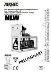
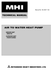
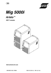
1
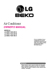
SERVICE MANUAL
MULTI CONTROL
EN
IT
MultiControl_Specifiche_SAT_Ed1
Revision
Servizio Regolazione e Controllo
File
MultiControl_Specifiche_SAT_Ed1
1
Author
SAT
Date
23 October 2012
Page 1/54
Tipo
Specification SAT
Summary INTRODUCTION .......................................................................................................................................................... 3 Hardware Architecture ........................................................................................................................................... 3 SYSTEM STRUCTURE ................................................................................................................................................ 4 TYPES OF SYSTEMS ................................................................................................................................................... 5 VMF-CRP FOR THE MULTICONTROL SYSTEM ................................................................................................ 7 Connections of VMF CRP 1 (control of 3-way valves and sensors) ....................................................................... 8 Connections of VMF CRP 2 (control of immersion heater for domestic hot water)............................................... 9 Connections of VMF CRP 3 (remote controls) ..................................................................................................... 10 SERIAL CONNECTION MULTI CONTROL ......................................................................................................... 11 USER INTERFACE PANEL MULTI CONTROL ................................................................................................... 12 MAIN SCREEN ........................................................................................................................................................... 13 HEAT PUMP MONITOR SCREEN .......................................................................................................................... 14 FUNCTIONS ................................................................................................................................................................ 15 BASIC USE PROCEDURES ......................................................... ERRORE. IL SEGNALIBRO NON È DEFINITO. MAIN SCREEN SELECTION ................................................................................................................................... 16 UNIT OVERVIEW: MAIN SCREEN 1.0 .................................................................................................................. 17 UNIT OVERVIEW: PARAMETERS SCREEN 1.1 ................................................................................................. 18 UNIT OVERVIEW: TIME-CLOCK PROGRAMMING SCREEN 1.2 ................................................................. 19 DOMESTIC HOT WATER OVERVIEW: MAIN SCREEN 2.0 ............................................................................ 20 DOMESTIC HOT WATER OVERVIEW: TIME-CLOCK PROGRAMMING DHW 2.1 .................................. 21 DOMESTIC HOT WATER OVERVIEW: ANTI-LEGIONELLA MENU 2.2 ..................................................... 21 USER MENU SELECTION 3.0 .................................................................................................................................. 22 DATE AND TIME MENU: SETTING THE TIME 3.1.1 ........................................................................................ 22 DATE AND TIME MENU: SETTING THE DATE 3.1.2 ........................................................................................ 23 SEASON MENU: SETTING THE SEASON 3.2.1 ................................................................................................... 24 DISPLAY MENU: SETTING THE LANGUAGE 3.3.1 ........................................................................................... 24 DISPLAY MENU: SETTING THE CONTRAST 3.3.2 ............................................................................................ 25 DISPLAY MENU: SETTING THE SCREEN SAVER 3.3.3 ................................................................................... 25 ALARM HISTORY 4.0 ............................................................................................................................................... 26 SETUP MENU 5.0 ........................................................................................................................................................ 27 SETUP MENU: PASSWORD SCREEN 5.1 .............................................................................................................. 27 SYSTEM SETUP MENU: NUMBER OF UNITS 5.1.1.0 ......................................................................................... 28 SYSTEM SETUP MENU: STANDBY UNIT 5.1.1.1 ................................................................................................ 29 SYSTEM SETUP MENU: TYPE OF ROTATION 5.1.1.2 ...................................................................................... 29 SYSTEM SETUP MENU: TYPE OF CONTROL 5.1.1.3 ........................................................................................ 31 DELTA T Control ................................................................................................................................................. 32 FREE Control ....................................................................................................................................................... 33 LOAD Control ...................................................................................................................................................... 34 SYSTEM SETUP MENU: ON/OFF DELAY 5.1.1.4 ................................................................................................ 34 Revision
Servizio Regolazione e Controllo
File
MultiControl_Specifiche_SAT_Ed1
1
Author
SAT
Date
23 October 2012
Page 2/54
Tipo
Specification SAT
SYSTEM SETUP MENU: CAPACITY ON/OFF CHILLERS 5.1.1.5 .................................................................... 35 SYSTEM SETUP MENU: ON TEMPERATURE 5.1.1.6 ........................................................................................ 36 SYSTEM SETUP MENU: OFF TEMPERATURE 5.1.1.7 ...................................................................................... 36 UNIT SETUP MENU: HEATING SETPOINT 5.1.2.1 ............................................................................................. 38 UNIT SETUP MENU: COOLING SETPOINT 5.1.2.2 ............................................................................................ 38 UNIT SETUP MENU: SETPOINT COMPENSATION 5.1.2.3............................................................................... 39 UNIT SETUP MENU: TYPE OF UNIT 5.1.2.4......................................................................................................... 40 DHW SETUP MENU: NUMBER OF HEAT PUMP UNITS FOR DHW 5.1.3.0 .................................................. 41 DHW SETUP MENU: SIMULTANEOUS LOADS 5.1.3.1 ...................................................................................... 42 DHW SETUP MENU: DELAY START IMMERSION HEATER 5.1.3.2 ............................................................. 43 DHW SETUP MENU: VALVE ROTATION 5.1.3.3 ................................................................................................ 44 DHW SETUP MENU: ON/OFF RANGE 5.1.3.4 ...................................................................................................... 44 DHW SETUP MENU: HYSTERESIS DELTA 5.1.3.5 ............................................................................................. 45 DHW SETUP MENU: DEFROST POSITION 5.1.3.7 ............................................................................................. 46 SYSTEM SETUP MENU: REMOTE CONTROL 5.1.4.0 ....................................................................................... 47 SYSTEM SETUP MENU: BAUD RATE 5.1.4.1 ....................................................................................................... 53 SYSTEM SETUP MENU: SERIAL ADDRESS 5.1.4.2 ............................................................................................ 53 SYSTEM SETUP MENU: EXPANSION PRESENT 5.1.4.3 ................................................................................... 53 Revision
Servizio Regolazione e Controllo
File
MultiControl_Specifiche_SAT_Ed1
1
Author
SAT
Date
23 October 2012
Page 3/54
Tipo
Specification SAT
INTRODUCTION
The Multicontrol is a control system dedicated to simultaneously manage several refrigeration units to:
Control starting, stopping and operating setpoint of a maximum of four units in autonomous mode or as
slaves in a system controlled by a BMS or supervisory system.
Remote control where the controls and information of a refrigeration unit/heat pump unit are centralised.
Hardware Architecture
The Multicontrol system hardware is characterised by the combination of electronic components:
Multicontrol board, with part number 9118368.
VMF-CRP expansion boards, with part number 9113073
Serial interface board for ModBus and supervisor systems or BMS (optional).
Sensor to locate in the DHW tank.
Sensor to locate at the inlet (SIW) or outlet (SUW) of the hydraulic parallel circuit SPLW.
External air sensor KSAE.
Revision
Servizio Regolazione e Controllo
File
MultiControl_Specifiche_SAT_Ed1
1
Author
SAT
Date
23 October 2012
Page 4/54
Tipo
Specification SAT
SYSTEM STRUCTURE
SUPERVISOR
VMF
SYSTEM
MULTICONTROL
OR BMS
RS485 serial for BMS
RS485 serial for VMF-Multichiller system
VMF
VMF
VMF
CRP1
CRP2
CRP3
Figure 1: System structure for controlling multiple chillers in parallel
SUPERVISOR
SYSTEM
OR BMS
VMF
MULTICHILLER
RS485 serial for BMS
RS485 serial for VMF-Multichiller system
Figure 2: System structure as remote panel to chiller
Revision
Servizio Regolazione e Controllo
File
MultiControl_Specifiche_SAT_Ed1
1
Author
SAT
Date
23 October 2012
Page 5/54
Tipo
Specification SAT
TYPES OF SYSTEMS
The VMF-Multichiller system is developed to manage the type of systems with configurations like the examples
shown below:
SUW
System load
Decoupler
SIW
Primary circuit
Secondary circuit
Figure 3: System with four chillers for producing the system water
Revision
Servizio Regolazione e Controllo
File
MultiControl_Specifiche_SAT_Ed1
1
Author
SAT
Date
23 October 2012
Page 6/54
Tipo
Specification SAT
Figure 4: System with four chillers for the production of system water and domestic hot water
VMF-CRP (1) Accessory module for the control of:
•
3-way diverting valve
•
System water inlet and outlet sensors (SIW, SUW)
•
Domestic hot water tank sensor (SAS)
•
Accessory KSAE for external air temperature sensor (SAE)
VMF CRP (2) Accessory module for the control of:
•
Electric immersion heater in the domestic hot water tank
VMF CRP (3) Accessory module for the remote control of several functions:
•
System On/Off, Alarm reset, Season changeover (through inputs)
•
System alarms present, System status (ON/OFF), System season status (HEATING/COOLING), Alarm
present in one of the units
Revision
Servizio Regolazione e Controllo
File
MultiControl_Specifiche_SAT_Ed1
1
Author
SAT
Date
23 October 2012
Page 7/54
Tipo
Specification SAT
VMF-CRP for the MULTICONTROL system
POWER SUPPLY
•
The alternating current power installation must use a transformer with voltage output of 24 Vac with safety
Class II with at least 15 VA rating, for the power supply of only one expansion module, between terminals
G and G0.
•
The power supply is functionally isolated from all the I/O and serial interfaces.
•
A protective fuse of 800 mA is required for the power supply.
•
It is recommended to keep apart the power supply of the expansion board pCOE from the rest of the
electrical devices (contactors and other electromechanical components) within the electrical panel.
•
It is necessary to use a ferrite (type KITAGAWA part. n. RI 18-28-10 c0o7d8. 7C7aAreXlX 0) through which
the power supply cable must be twice wound round.
•
The minimum cable cross section for the power supply cable must be 1mm.
EXAMPLE ADDRESS 1
EXAMPLE ADDRESS 5
LED signal description
LED red
LED yellow
LED green
description
on
on
Communication active and functioning
on
on
flashing
Sensor error
Software error, contact Aermec
on
Loss of communication (check addresses, cables)
Awaiting system initialisation from the master (max. 30 s)
Revision
Servizio Regolazione e Controllo
File
MultiControl_Specifiche_SAT_Ed1
1
Author
SAT
Date
23 October 2012
Page 8/54
Tipo
Specification SAT
Connections of VMF CRP 1 (control of 3-way valves and sensors)
Code
SIW
SUW
AE
AS
Component
Primary hydraulic circuit INLET water sensor
Secondary hydraulic circuit OULET water sensor
External air sensor
Domestic hot water tank sensor
Code
3VD (1)
3VD (2)
3VD (3)
3VD (4)
Valve controller
3-way diverting valve unit 1
3-way diverting valve unit 2
3-way diverting valve unit 3
3-way diverting valve unit 4
Input to enable the sensor
ID1 (CLOSED) on terminal J4
ID2 (CLOSED) on terminal J4
ID3 (CLOSED) on terminal J4
ID4 (CLOSED) on terminal J4
Output
J5
J6
J7
J8
Available as
Accessory SPLW (1)
Accessory SPLW (2)
Accessory KSAE
Accessory SDHW
Available as
Component NOT supplied
Component NOT supplied
Component NOT supplied
Component NOT supplied
Revision
Servizio Regolazione e Controllo
File
MultiControl_Specifiche_SAT_Ed1
1
Author
SAT
Date
23 October 2012
Page 9/54
Tipo
Specification SAT
Connections of VMF CRP 2 (control of immersion heater for domestic hot water)
Code
RAS
Component
Control electric immersion heater for domestic hot water
Code
ARE
PRE
Component
Heater alarm present input ID1 CLOSED= No alarm / ID1 OPEN= Alarm
Enable heater present CLOSED= Heater present in system / OPEN= No heater in system
Output
J5
Available as
Component NOT supplied
Input
J4
J4
Available as
Component NOT supplied
Component NOT supplied
Revision
Servizio Regolazione e Controllo
File
MultiControl_Specifiche_SAT_Ed1
1
Author
SAT
Date
23 October 2012
Page 10/54
Tipo
Specification SAT
Connections of VMF CRP 3 (remote controls)
Output Code
J5 ASG
J6 SGS
J7 SSI
J8 ASM
Function
General System Alarm (system alarm present)
General System Status
System Season Status
Unit System Alarm (an alarm present in one of the units)
Input Code
ID1 AGI
ID2 RGS
ID3 CCS
General System Enable
Reset General System
Control Season Change
Function
Status
Closed = System alarm
Closed = System is ON
Closed = WINTER
Closed = Alarm present
Status
Closed = System enabled
Closed = Reset system
Closed = WINTER setting
Status
Open = No system alarm
Open = System is OFF
Open = SUMMER
Open = No alarm present
Status
Open = System disable
Open = SUMMER setting
Revision
Servizio Regolazione e Controllo
File
MultiControl_Specifiche_SAT_Ed1
1
Author
SAT
Date
23 October 2012
Page 11/54
Tipo
Specification SAT
Serial connection MULTI CONTROL
WARNING: If the Multicontrol is installed in a system controlled through the VMF system any control of the
production of domestic hot water must be done by the Multicontrol (the accessory VMF-ACS is not compatible with
the Multicontrol accessory, hence both cannot be present in the same system).
Revision
Servizio Regolazione e Controllo
File
MultiControl_Specifiche_SAT_Ed1
1
Author
SAT
Date
23 October 2012
Page 12/54
Tipo
Specification SAT
User interface panel MULTI CONTROL
The accessory MULTICONTROL allows the control and management of up to four chillers (fitted with the
MODUCONTROL electronic board); through this accessory the user can control:
•
ON/OFF of the unit (based on the selected logic)
•
Reading of chiller parameters (temperatures, pressures, setpoints, etc.)
•
Time-clock control (up to two daily settings for each day of the week)
•
Control of domestic hot water (production DHW, time-clock control of DHW, anti-legionella cycle, etc.)
•
Control of operating mode (cooling or heating mode operation)
•
Alarm history (the systems allows the recording of the last 10 system alarms).
Warning: to use some of the system functions it is necessary to use one or more VMF-CRP modules, as shown in
the system schematic.
Key
Function
A
ON/OFF key
B
C
D
Multi-function keys; the associated
functionality changes based on which
screen is shown on the display
E
F
Key to select and confirm (Enter)
G
Key to decrease value (-)
H
Key to increase value (+)
I
White back-lit LCD display128 x 64 pixel
L
LED not used
M
LED not used
N
LED red when signalling alarm present
Revision
Servizio Regolazione e Controllo
File
MultiControl_Specifiche_SAT_Ed1
1
Author
SAT
Date
23 October 2012
Page 13/54
Tipo
Specification SAT
MAIN SCREEN
Main screen where the principal parameters of the refrigeration units is shown. From this point all other sub-menus
can be accessed. The following describes the icons displayed:
Operating
Chiller status
season
General
On/Off
Unit number
Alarm present
(U1, U2, U3, U4, MIX)
System leaving water
Time-clock
temperature
present
System entering water
temperature
Day, date, time
External air
temperature
Figure 5: Main screen
In the “Chiller status” the chillers present in the system are identified and for each of these the following displays
are possible:
•
indicates that the chiller is OFF from local or remote control
•
indicates that the chiller is in standby mode
•
indicates the chiller circulator is active
•
indicates that the chiller compressor + circulator is active
•
indicates that the chiller is not communicating with the ModBus network
•
indicates a chiller fault is present
•
indicates that the chiller is in defrost mode
Revision
Servizio Regolazione e Controllo
File
MultiControl_Specifiche_SAT_Ed1
1
Author
SAT
Date
23 October 2012
Page 14/54
Tipo
Specification SAT
MAIN
System
On/Off
PAGE
Change tab to show
unit data
To sub-menu of application
Heat pump monitor screen
In this screen the characteristics of the heat pump thermostat controllers is summarised.
Icon indicating the heat
pump status
Chiller number
Demand (%) of each
Entering water
chiller thermostat
temperature each chiller
Capacity (%) actually required
Leaving water
for compressor of each chiller
temperature each chiller
Revision
Servizio Regolazione e Controllo
File
MultiControl_Specifiche_SAT_Ed1
1
Author
SAT
Date
23 October 2012
Page 15/54
Tipo
Specification SAT
FUNCTIONS
MAIN SCREEN
LEGEND:
User 101
SELECTION MENU
HEAT PUMP MONITOR
Technician 303
UNIT OVERVIEW
DOMESTIC HOT WATER
OVERVIEW
USER SUB-MENU
ALARM HISTORY
PASSWORD SCREEN
UNIT PARAMETERS
DHW TIMER SCHEDULE
CHILLER TIMER SCHEDULE
ANTI-LEGIONELLA
SETUP MENU
SET
TIME
SET
SEASON
SET
DATE
SET
LANGUAGE
SET
CONTRAST
SET
SCREENSAVER
NUMBER
CHILLERS 303
HEAING SETPOINT
101
NUMBER OF HEAT PUMP
UNITS FOR DHW 303
ENABLE REMOTE
CONTROL 101
STANDBY CHILLER
PRESENT
COOLING SETPOINT
SIMULTANEOUS LOADS
BAUD RATE
TYPE OF ROTATION
SETPONT COMPENSATION
DELAY STARTING
IMMERSION HEATER
SERIAL ADDRESS
TYPE OF CONTROL
TYPE OF UNIT
VALVE ROTATION
PRESENCE
SENSORS/VALVES
ON/OFF CHILLERS DELAY
TIMER
ON/OFF RANGE
PRESENCE I/O
% CAPACITY CHILLERS
FOR ON/OFF
DIFFERTIAL START NEXT
HEAT PUMP UNIT
RS485 NETWORK STATUS
START TEMP CHILLERS
TYPE OF DEFROST
STOP TEMP CHILLERS
Figure 6: Application menu structure
Revision
Servizio Regolazione e Controllo
File
MultiControl_Specifiche_SAT_Ed1
1
Author
SAT
Date
23 October 2012
Main screen selection
From this screen it is possible to see the required menu.
Line
identifying
the
selected menu
Keys used to select the
menu
Figure 7: Menu selection
From the selections of the main screen the following can be accessed:
•
UNIT OVERVIEW
•
DHW OVERVIEW (displayed if enabled in the system)
•
•
•
USER MENU
SETUP MENU
ALARM HISTORY
Page 16/54
Tipo
Specification SAT
Revision
Servizio Regolazione e Controllo
File
MultiControl_Specifiche_SAT_Ed1
1
Author
SAT
Date
23 October 2012
Page 17/54
Tipo
Specification SAT
Unit overview: main screen 1.0
From the unit overview the operating status of each unit in the system can be seen.
Index of chiller being
displayed
Leaving unit temperature
macchina
Operating
Setpoint temperature
Unit status
Unit enabling
If a chiller alarm is present the unit overview screen becomes:
Active alarm code
Present alarm reset key
To change the index value of the chiller to be displayed follow this procedure:
1. Press the key
2. With the keys
and
3. Press the key
to confirm the data
Through the keys
and
increase/decrease the index, range 1 to 4
the display passes between the previous or next screen of the application.
Revision
Servizio Regolazione e Controllo
File
MultiControl_Specifiche_SAT_Ed1
1
Author
SAT
Date
23 October 2012
Page 18/54
Tipo
Specification SAT
Unit overview: parameters screen 1.1
From the chiller overview main screen the screen for reading the parameters of the chiller can be accessed.
Line that identifies
Parameter
the parameter
Keys to select the
parameter to display
The parameters that can be displayed are:
ANR
Parameter
Description
ANL
ANLi
ANF
ANL-C
WRL
SRP
TYPE
Type of unit
TIA
Water inlet temperature
TUA
Water outlet temperature
TSB
Coil temperature
TGP
Discharge gas temperature
SIWH
Water inlet temperature (condenser)
SUWH
Water outlet temperature (condenser)
TAE
External air temperature
AP
High pressure
BP
Low pressure
HC0
Primary circuit compressor operating hours
SP0
Primary circuit compressor number of starts
REL
PRIMARY software version
BLD
SECONDARY software version
SET
Unit control setpoint
HC1
Secondary circuit compressor operating hours
SP1
Secondary circuit compressor number of starts
STF
Cooling setpoint
STC
Heating setpoint
SAS
Domestic hot water setpoint
PT
Capacity percentage requested by the thermostat
PO
Capacity provided by the unit (on/off units) or operating frequency (units
with inverter compressors)
Through the keys
and
the display passes between the previous or next screen of the application.
ANKi
Revision
Servizio Regolazione e Controllo
File
MultiControl_Specifiche_SAT_Ed1
1
Author
SAT
Date
23 October 2012
Page 19/54
Tipo
Specification SAT
Unit overview: time-clock programming screen 1.2
For each chiller it is possible to enable the time-clock programming. This allows a maximum of two daily settings for
each day of the week.
It is possible to have chillers with time-clock programmes in a system (the same for each) and other chillers
enabled and operating without any daily restriction. This is all at the discretion of the system user.
Chiller/heat
pump
index
First
Programme day
daily
time-clock
Second daily timeclock
Copy programme key
for every days of the
week
Key to enable time-clock
Key to change day of the
programme for the specific
week
chiller
OFF
ON
OFF
ON
Time-clock 1
On 1
00:00
OFF
Time-clock 2
Stop 1
On 2
Stop 2
23:59
To utilise the two time-clock programmes set all the parameters for the first and second daily time-clock
programmes.
OFF
ON
OFF
Time-clock 1
00:00
On 1
Stop 1
23:59
To utilise just one time-clock programme leave the parameters as 00:00 in the second time-clock programme.
Revision
Servizio Regolazione e Controllo
File
MultiControl_Specifiche_SAT_Ed1
1
Author
SAT
Date
23 October 2012
Page 20/54
Tipo
Specification SAT
To set the time-clock programme follow this procedure:
1. Press the key
2. With the keys
and
3. Press the key
to confirm and save the data
increase/decrease the hour/minutes fields selected
4. Repeat the procedure from step 2 until the field for the minutes to STOP the second time-clock.
Through the keys
and
the display passes between the previous or next screen of the application.
Domestic hot water overview: main screen 2.0
From the domestic hot water overview the relevant parameters for the production of domestic hot water are
displayed.
DHW
Storage
temperature
overview
DHW setpoint
tank
Manual enabling
immersion
heater
Enabling DHW production
In this screen the required temperature for the domestic hot water can be set and can also be linked to the
maximum operating temperature of the heat pump unit present in the system, or not linked from this limit if there is
installed an immersion heater/boiler for DHW.
To change the value of “DHW temperature” follow this procedure:
1. Press the key
2. With the keys
and
3. Press the key
to confirm and save the data
Through the keys
and
increase/decrease the value, range 20.0 to 70.0 °C
the display passes between the previous or next screen of the application.
Revision
Servizio Regolazione e Controllo
File
MultiControl_Specifiche_SAT_Ed1
1
Author
SAT
Date
23 October 2012
Page 21/54
Tipo
Specification SAT
Domestic hot water overview: time-clock programming DHW 2.1
In this screen the production of hot water time-clock can be programmed. This menu is very similar to that of the
chiller: for further information refer to that section.
Through the keys
and
the display passes between the previous or next screen of the application.
Domestic hot water overview: anti-legionella menu 2.2
Start time of anti-legionella
cycle
Day anti-legionella cycle is
enabled
Enabling antilegionella cycle
To programme the parameters of the anti-legionella cycle:
1. Press the key
2. With the keys
and
increase/decrease the value of the hour or whether it is enabled/disabled the
day of the week
to confirm and save the data
3. Press the key
4. Repeat the procedure from item 2 until the last field (DOM)
Through the keys
and
the display passes between the previous or next screen of the application.
Revision
Servizio Regolazione e Controllo
File
MultiControl_Specifiche_SAT_Ed1
1
Author
SAT
Date
23 October 2012
Page 22/54
Tipo
Specification SAT
The anti-legionella cycle brings the temperature of the domestic hot water storage tank up 65 °C for 3 minutes. To
do this the system begins the phase by starting the heat pump units available for heating the water up to their
maximum working temperature. Reaching the end temperature of the cycle is achieved by a second step by
activating the immersion electrical heater fitted in the tank.
User menu selection 3.0
From this screen the user menu to be displayed can be selected.
Line showing the user
menu selected
Keys to select the user
menu
From the selection of user menu access is made to:
•
date/time menu
•
display menu
•
operating season menu
Date and time menu: setting the time 3.1.1
In this screen the time can be set for the system panel.
To change the hour follow this procedure:
Revision
Servizio Regolazione e Controllo
File
MultiControl_Specifiche_SAT_Ed1
1
Author
SAT
Date
23 October 2012
Page 23/54
Tipo
Specification SAT
1. Press the key
2. With the keys
and
3. Press the key
to confirm and save the data
increase/decrease the value
4. Repeat the procedure from item 2 until the seconds are modified
Through the keys
and
the display passes between the previous or next screen of the application.
Date and time menu: setting the date 3.1.2
In this page the date of the system can be set.
To change the date and day follow this procedure:
1. Press the key
2. With the keys
and
3. Press the key
to confirm and save the data
increase/decrease the value or the line
4. Repeat the procedure from item 2 until the modification of the day
Through the keys
and
the display passes between the previous or next screen of the application.
Revision
Servizio Regolazione e Controllo
File
MultiControl_Specifiche_SAT_Ed1
1
Author
SAT
Date
23 October 2012
Page 24/54
Tipo
Specification SAT
Season menu: setting the season 3.2.1
In this screen the operating season of the system can be set.
To change the season follow this procedure:
1. Press the key
2. With the keys
and
3. Press the key
to confirm and save the data
Through the keys
and
select from the two options: SUMMER, WINTER
the display passes between the previous or next screen of the application.
Display menu: setting the language 3.3.1
In this screen the reference language for the lines shown on the system can be set.
To change the language follow this procedure:
1. Press the key
2. With the keys
and
3. Press the key
to confirm and save the data
Through the keys
and
select from the five options: Italian, English, French, German, Spanish
the display passes between the previous or next screen of the application.
Revision
Servizio Regolazione e Controllo
File
MultiControl_Specifiche_SAT_Ed1
1
Author
SAT
Date
23 October 2012
Page 25/54
Tipo
Specification SAT
Display menu: setting the contrast 3.3.2
In this screen the LCD contrast can be set to improve the visibility of the screens.
To change the value of the contrast follow this procedure:
1. Press the key
2. With the keys
and
3. Press the key
to confirm and save the data
Through the keys
and
increase/decrease the value of the contrast, range: 0 to 100 %
the display passes between the previous or next screen of the application.
Display menu: setting the screen saver 3.3.3
In this screen the functionality of the screen saver can be set. This function allows the user to set a timer for the
application to force the display of the main screen.
To change the value of the screen saver follow this procedure:
1. Press the key
2. With the keys
and
3. Press the key
to confirm and save the data
increase/decrease the screen saver timer, range: 0 to 60 minutes
The icon present in the screen will be shown as:
Revision
Servizio Regolazione e Controllo
File
MultiControl_Specifiche_SAT_Ed1
1
Author
SAT
•
Date
23 October 2012
Page 26/54
Tipo
Specification SAT
for screen saver values greater than 0 (screen saver active)
•
for screen saver value equal to 0 (screen saver not active)
Through the keys
and
the display passes between the previous or next screen of the application.
Alarm history 4.0
In this screen the last (maximum 10) system alarms can be seen.
Line that identifies the system
element that generated the
alarm
Index of the
alarm
Line that identifies the
history
type of alarm
Alarm history
Time and date of
reset key
alarm event
Alarm source
System
Unit
Alarm name
Description
Eeprom error
Initialisation error of the Multicontrol memory
Not connected
Unit not connected to the RS485 network of the VMF-Multichiller
AL xxx (alarm code given by the unit: see the
Alarm defined by the unit
alarm code generated by the board)
No anti-legionella
DHW
The anti-legionella cycle did not terminate correctly
No hot water
The DHW production cycle did not terminate correctly
DHW setting error
The operating setpoint is greater than the maximum working
Expansion not connected
Expansion not connected to RS485 network of VMF-Multichiller
temperature of the heat pump unit and there is no immersion heater
VMF CRP 1
VMF CRP 2
VMF CRP 3
SUW sensor faulty
Leaving mixed water temperature sensor faulty
SIW sensor faulty
Entering mixed water temperature sensor faulty
SSAN sensor faulty
DHW sensor faulty
SAMB sensor faulty
External air temperature sensor faulty
Expansion not connected
Expansion not connected to RS485 network of VMF-Multichiller
Heater faulty
Immersion heater faulty
Expansion not connected
Expansion not connected to RS485 network of VMF-Multichiller
Revision
Servizio Regolazione e Controllo
File
MultiControl_Specifiche_SAT_Ed1
1
Author
SAT
Date
23 October 2012
Page 27/54
Tipo
Specification SAT
Setup menu 5.0
In this screen the specific installation/setup menu can be selected.
The user can access the following from this menu:
•
system setup
•
setup chillers/heat pump units
•
setup DHW
•
system setup.
Setup menu: password screen 5.1
To access the menus below insert the password relevant to the level of access.
With password:
•
101 (user): only the parameters accessible to the user are displayed
•
303 (technician): displays all the parameters
Field to insert
the password
Line that shows the application
software version
Revision
Servizio Regolazione e Controllo
File
MultiControl_Specifiche_SAT_Ed1
1
Author
SAT
Date
23 October 2012
Page 28/54
Tipo
Specification SAT
To enter the password follow this procedure:
1. Press the key
2. With the keys
and
3. Press the key
to confirm the data
increase/decrease the selected digit
4. Repeat item 2 of the procedure until the third digit
System setup menu: number of units 5.1.1.0
In this screen the number of chillers/heat pump units present in the system are shown. Access level: technician
303.
To show the number of units present in the system follow this procedure:
1. Press the key
2. With the keys
and
3. Press the key
to confirm the data
Through the keys
and
Legend:
increase/decrease the data, range 0 to 4
the display passes between the previous or next screen of the application.
Unit 1
Unit 2
Unit 3
Unit 4
Address underlined shows
any standby unit
Number of chillers
Address
Address
Address
Address
1
200
//
//
//
2
//
201
//
//
3
//
//
202
//
4
//
//
//
203
Table 1: ModBus addresses of the units present in the system
Revision
Servizio Regolazione e Controllo
File
MultiControl_Specifiche_SAT_Ed1
1
Author
SAT
Date
23 October 2012
Page 29/54
Tipo
Specification SAT
System setup menu: standby unit 5.1.1.1
In this screen the presence of any standby chiller/heat pump unit is shown. Access level: technician 303.
Systems with a standby unit have available a unit that is only activated if there is a fault with the main group. The
standby unit is identified in the system with the highest modbus address (see Table 1).
To select the presence of a standby chiller follow this procedure:
1. Press the key
2. With the keys
3.
and
to confirm the data
Press the key
Through the keys
select the line “PRESENTE” (present) or “ASSENTE” (absent)
and
the display passes between the previous or next screen of the application.
System setup menu: type of rotation 5.1.1.2
In this menu the choice of how the units will be activated or deactivated during the control of the system can be
made. Access level: technician 303.
To select the type of rotation follow this procedure:
1. Press the key
2. With the keys
3.
Press the key
and
select the line “FISSA” (fixed) or “EQUILIBRATA” (balanced)
to confirm the data
Revision
Servizio Regolazione e Controllo
File
MultiControl_Specifiche_SAT_Ed1
1
Author
SAT
Date
Through the keys
23 October 2012
and
Page 30/54
Tipo
Specification SAT
the display passes between the previous or next screen of the application.
FISSA (fixed): With fixed type of rotation the switch on and switch off sequence is determined as shown in the
figure:
C2
C1
T0 start
C3
C4
Figure 8: Fixed starting sequence
C3
C4
C2
C1
T0 stop
Figure 9: Fixed stopping sequence
EQUILIBRATA (balanced): This logic balances the operating hours of the units; practically the unit with the least
operating hours is started first, following this logic with the subsequent units.
For example:
C4
Compressor operating hours
C1
C2
T0 start
C3
Revision
Servizio Regolazione e Controllo
File
MultiControl_Specifiche_SAT_Ed1
1
Author
SAT
Date
23 October 2012
Page 31/54
Tipo
Specification SAT
Whilst the stopping sequence the unit with the highest operating hours is stopped first, following the same logic
with subsequent units. This type of rotation ensures that the units are enabled and disabled in a manner to ensure
equal operating hours.
For example:
C2
Compressor operating hours
C3
C1
C4
T0 stop
Note:
The parameter “Tipo di rotazione” (type of rotation) is not considered during the production of domestic hot water.
In this mode the rotation control rule is FIFO (first in first out) and is tied to the index (ModBus serial number) of the
unit.
C4
C3
C2
T start DHW
C1
T stop DHW
Figure 10: Start/stop sequence during the production of domestic hot water
System setup menu: type of control 5.1.1.3
In this screen the control mode required for the system use is selected. Access level: technician 303.
To select the type of control follow this procedure:
Revision
Servizio Regolazione e Controllo
File
MultiControl_Specifiche_SAT_Ed1
1
Author
SAT
Date
23 October 2012
Page 32/54
Tipo
Specification SAT
Press the key
1. With the keys
2.
and
select the line “CARICO” (load), “DELTA T” or “LIBERO” (free)
to confirm the data
Press the key
and
Through the keys
the display passes between the previous or next screen of the application.
DELTA T Control
With “DELTA T” control the type of hydraulic system used has to be defined, which can be:
•
Single circuit [
•
Double circuit [
]
]
Specifically, the menu “Tipo di regolazione” (type of control) is shown as in the following figure:
Icon
defining
the
type of system
Key to change
system type
With the control for “DELTA T” the units are controlled in relation to the operating season and the entering and
leaving temperature of the units. To use this control method the expansion module VMF-CRP1 has to be
installed. In this mode for each unit it is determined:
Enabling in relation to the system
Enabling in relation to the operating season
Switch on in relation to the trend of water temperature produced by the units and accordingly dictated by
the type of rotation
Operating setpoint (fixed or with compensation)
Unit diagnostics
As noted before, the installer must set the system type for this mode of control (single/double circuit). This
parameter is fundamental for the correct control of the units.
Revision
Servizio Regolazione e Controllo
File
MultiControl_Specifiche_SAT_Ed1
1
Author
SAT
Date
23 October 2012
Page 33/54
Tipo
Specification SAT
For double circuit systems and specifically for systems where the secondary circuit water flow is by an independent
pump, the SUW sensor must accurately read the liquid temperature to ensure the correct control operation. In
these types of system all the units (and their circulators) can be switched off once the load is met.
For single circuit systems the water flow (and hence reading of the sensor SUW) is ensured by the circulators
present in the units. In these types of systems at least one unit must be operating, even when the load is
met. To configure the correct mode of operation for the units the following parameters must be set for this mode:
On/Off Delay
Temperature On
Temperature Off
Type of installation
The DELTA T mode requires the following:
VMF-CRP1 present
SUW sensor active
SIW sensor active
If any one of these is missing the system will change to the FREE mode.
FREE Control
With the “LIBERA” (free) control the units are controlled independently, and for each is determined:
Enabling in relation to the system
Operating setpoint (fixed or with compensation)
Unit diagnostics
In this mode the units are not forced start/stop in relation to the load, and the units control autonomously in relation
to their own thermostat.
An example of this type of control is four pipe systems (producing simultaneous cold ad hot water).
Revision
Servizio Regolazione e Controllo
File
MultiControl_Specifiche_SAT_Ed1
1
Author
SAT
Date
23 October 2012
Page 34/54
Tipo
Specification SAT
LOAD Control
With the “CARICO” (load) control are controlled in relation to the operating season and the effective load demand
determined analysing the unit thermostats for the running units. For each is determined:
Enabling in relation to the system
Enabling in relation to the operating season
Enabling in relation to the load demand and according to the sequence determined by the type of rotation
Operating setpoint (fixed or compensation)
Unit diagnostics
To correctly configure the unit operation in this mode the following parameters must be set:
On/Off Delay
On/Off Capacity
System setup menu: ON/OFF delay 5.1.1.4
In this screen the start and stop delay timers for the chillers can be selected according to the selected control logic
(for Load or Delta T).
Access level: user 101.
Delay start timer: shows the required
time that must pass from the system
capacity request to the enabling of the
required unit
Delay stop timer: shows the
require time that must pass from the
system reaching requested capacity
to stopping of the required unit
To select the delay times follow this procedure:
1. Press the key
2. With the keys
3.
and
increase/decrease the value, range 0 to 300 s
to confirm and save the data
Press the key
4. Repeat the procedure from item 2 until the ON->OFF field
Through the keys
and
the display passes between the previous or next screen of the application.
File
MultiControl_Specifiche_SAT_Ed1
1
Author
SAT
Date
23 October 2012
Page 35/54
Tipo
Specification SAT
SUW
Revision
Servizio Regolazione e Controllo
CHILLER
ON/OFF
[s]
CHILLER
STATUS
[s]
Delay ON → OFF
Delay OFF → ON
[s]
System setup menu: capacity ON/OFF chillers 5.1.1.5
In this screen the capacity percentages (obtained from the thermostats of the various refrigeration units) can be set
for the levels to start or stop the next chiller. These parameters are used when Type of control is set as load.
Access level: user 101.
Capacity level needed to stop a
further unit: shows the maximum
percentage value that must be
required from each thermostat of
running units before stopping the
last unit. The capacity of the first
units must reach 40% before
stopping the second
Capacity level needed to start a
further unit: shows the minimum
percentage value that must be
required from each thermostat of
running units before starting the
next unit. The capacity of the first
unit must reach 80% before starting
the second
To set the ON/OFF capacities follow this procedure:
1. Press the key
2. With the keys
3.
and
Press the key
increase/decrease the value, range 0 to 100 %
to confirm and save the data
4. Repeat the procedure from item 2 until the ON->OFF Next field
Through the keys
and
the display passes between the previous or next screen of the application.
Revision
Servizio Regolazione e Controllo
File
MultiControl_Specifiche_SAT_Ed1
1
Author
SAT
Date
23 October 2012
Page 36/54
Tipo
Specification SAT
System setup menu: ON temperature 5.1.1.6
In this screen the start temperature (referring to the system SUW sensor) can be set for the various units in the
system. This parameter is used when the Control type is set as DELTA T.
Access level: user 101.
Unit active season setting:
shows
which
season
the
displayed setpoint refers to
Unit active setting: shows the temperature
read by sensor SUW in the secondary circuit
as activation threshold for the units
(depending on the season the demand is
activated above or below the threshold set in
this parameter)
Change parameter for the
operating season
To set the chiller ON temperature follow this procedure:
1. Press the key
2. With the keys
3.
and
to confirm and save the data
Press the key
Through the keys
increase/decrease the value, range -10.0 to 70.0 [°C]
and
the display passes between the previous or next screen of the application.
System setup menu: OFF temperature 5.1.1.7
In this screen the stop temperature (referring to the system SIW sensor) can be set for the various units in the
system. This parameter is used when the Control type is set as DELTA T.
Access level: user 101.
Shows the season the
unit refers to
Unit selected
Unit disabling setting: shows the temperature
(sensor SIW) of the primary circuit return water
considered the stop threshold of the
corresponding unit (depending on the season the
demand is activated above or below the
threshold set in this parameter)
Keys to increase/decrease the chiller index
Change parameter for the
operating season
To set the chiller OFF temperature follow this procedures:
Revision
Servizio Regolazione e Controllo
File
MultiControl_Specifiche_SAT_Ed1
1
Author
SAT
Date
23 October 2012
Page 37/54
Tipo
Specification SAT
1. Press the key
2. With the keys
3.
and
to confirm and save the data
Press the key
Through the keys
increase/decrease the value, range -10.0 to 70.0 [°C]
and
the display passes between the previous or next screen of the application.
STOP C4
SIW
SUW
STOP C3
STOP C2
STOP C1
START
CHILLER1
[S]
CHILLER2
[S]
CHILLER3
[S]
CHILLER4
[S]
[S]
The temperature control of the chillers/heat pump units can only be carried out with the presence in the system of
the VMF-CRP1 expansion board which monitors the sensors SUW and SIW.
SUW
SECONDARY
SIW
Revision
Servizio Regolazione e Controllo
File
MultiControl_Specifiche_SAT_Ed1
1
Author
SAT
Date
23 October 2012
Page 38/54
Tipo
Specification SAT
Unit setup menu: heating setpoint 5.1.2.1
In this screen the heating mode leaving water setpoint of the heat pump unit can be set.
Access level: user.
Unit index being
configured
Keys to change
values
To set the heating setpoint follow this procedure:
1. Press the key
2. With the keys
3.
and
to confirm and save the data
Press the key
Through the keys
increase/decrease the value, range 10.0 to 70.0 [°C]
and
the display passes between the previous or next screen of the application.
Unit setup menu: cooling setpoint 5.1.2.2
In this screen the cooling mode leaving water setpoint of the chiller can be set.
Access level: user.
To set the cooling setpoint follow this procedure:
1. Press the key
2. With the keys
3.
and
to confirm and save the data
Press the key
Through the keys
increase/decrease the value, range -10.0 to 20.0 [°C]
and
the display passes between the previous or next screen of the application.
Revision
Servizio Regolazione e Controllo
File
MultiControl_Specifiche_SAT_Ed1
1
Author
SAT
Date
23 October 2012
Page 39/54
Tipo
Specification SAT
Unit setup menu: setpoint compensation 5.1.2.3
In this screen the external ambient based setpoint compensation for the chillers/heat pump units can be set. The
sensor to read the external air temperature can be:
1. Sensor S AMB
2. The average of the sensors installed in the units if the S AMB sensor is not present or faulty. Access level:
technician.
Shows the minimum external air temperature for compensation:
depending on operating mode (cooling or heating) this value will be
connected to the minimum or maximum leaving water value setpoint, as
shown in the graphs below
Shows the minimum or maximum operating
setpoint (based on heating or cooling mode)
connected to the MINIMUM air temperature
Show whether the data refers
to the compensation in cooling
or heating mode
Icon that represents the
Shows the maximum external air temperature
for compensation: depending on operating
mode (cooling or heating) this value will be
connected to the minimum or maximum
leaving water value setpoint, as shown in the
graphs below
slope of the curve
Key to select summer or
winter curve
Enabling key for the
compensation setpoint of
the unit
Shows the minimum or maximum operating
setpoint (based on heating or cooling mode)
connected to the MAXIMUM temperature
TWout [°C]
Tua2
35°C
Tua1
12°C
Tua1
40°C
Tua2
7°C
Tae1
-0.5°C
Tae2
15°C
TAext [°C]
Tae1
30°C
Tae2
35°C
To set the compensation setpoint for the chillers/heat pumps units follow this procedure:
1. Press the key
2. With the keys
3.
and
increase/decrease the value, range +20.0 to 70.0 [°C]
to confirm and save the data
Press the key
4. Repeat the procedure from item 2 until the Tua2 field
Through the keys
and
the display passes between the previous or next screen of the application.
Revision
Servizio Regolazione e Controllo
File
MultiControl_Specifiche_SAT_Ed1
1
Author
SAT
Date
23 October 2012
Page 40/54
Tipo
Specification SAT
Unit setup menu: type of unit 5.1.2.4
In this screen the type of unit installed in the system can be set. Access level: technician.
To set the unit type follow this procedure:
1. Press the key
2. With the keys
and
select one of the lines: SOLO FREDDO (cooling only), SOLO CALDO
(heating only), POMPA DI CALORE (heat pump unit)
3.
to confirm and save the data
Press the key
Through the keys
and
the display passes between the previous or next screen of the application.
This parameter is fundamental for systems with different unit types (cooling only, heating only, heat pump units).
Revision
Servizio Regolazione e Controllo
File
MultiControl_Specifiche_SAT_Ed1
1
Author
SAT
Date
23 October 2012
Page 41/54
Tipo
Specification SAT
DHW setup menu: number of heat pump units for DHW 5.1.3.0
In this screen the number of units used for the production of domestic hot water is selected. This parameter also
includes any standby unit (if it has been specified in the relevant parameter System setup menu: standby chiller).
Access level: technician.
To set the number of heat pump units for the production of hot water:
1. Press the key
2. With the keys
and
3. Press the key
to confirm and save the data
Through the keys
and
increase/decrease the data, range 0 to 4
the display passes between the previous or next screen of the application.
WARNING: to correctly set the unit control for the production of DHW the following instructions must be followed:
Unit modbus address: the units must have a specific modbus address to be correctly controlled by the
MULTICONTROL accessory. This address can only be set on the panel of the unit. The addresses to set depend
on the number and functions of the units in the system. To determine the correct addresses to apply to the units for
the production of DHW refer to the summary table on the next page.
Type of unit: in the event that there is a standby chiller in the system this unit will have the highest modbus
address and all the units have to be enabled for DHW production, hence they must all the heat pump units or
heating only units.
Type of system for DHW production: In this type of system, where a standby unit is required also for the
domestic hot water, it is required that ALL the units controlled from the MULTICONTROL are units suitable for the
production of domestic hot water (HEAT PUMP UNITS or HEATING ONLY UNITS). The standby unit is always the
last unit and the unit with the highest serial address number. This unit is not activated during the production of
domestic hot but will operate only if one or more of the main group are not available.
Revision
Servizio Regolazione e Controllo
File
MultiControl_Specifiche_SAT_Ed1
1
Author
SAT
Date
23 October 2012
System with 4 heat pump units
Page 42/54
Tipo
System with 3 heat pump units
Specification SAT
System with 2 heat pump
System with 1 heat
units
pump unit
Number of
units for
DHW
Add:200
Add:201
Add:202
Add:203
4
3
Add:201
Add:202
Add:200
Add:201
Add:200
//
//
//
//
//
//
//
//
//
//
2
1
Legend:
Add:200
//
DHW standby unit.
//
//
//
//
//
//
//
//
//
DHW unit
Type of system for the production of DHW without standby chiller:
The first three types of systems have one or more units for the production of DHW, although there can be other
cooling only chillers. In this case it is mandatory that the units and any cooling only chillers are set with the
remaining available serial addresses.
DHW setup menu: simultaneous loads 5.1.3.1
In this screen simultaneous system loads can be set as enabled (ON) or disabled (OFF).
Access level: user.
To enable or disable simultaneous loads:
1. Press the key
2. With the keys
and
3. Press the key
to confirm and save the data
Through the keys
and
select the ON or OFF line
the display passes between the previous or next screen of the application.
Revision
Servizio Regolazione e Controllo
File
MultiControl_Specifiche_SAT_Ed1
1
Author
SAT
Date
23 October 2012
Page 43/54
Tipo
Specification SAT
If “abilitazione carichi” (loads enabled) is ON the system can consider the case of simultaneous operation between
heat pump unit (intended as compressor and/or supplementary heater mounted on the refrigeration unit) and
immersion heater mounted in the domestic hot water. This method of operation can be used if there are no
electrical power supply limits.
If there are electrical power supply limits, or if electrical consumption is to be minimised, the “abilitazione carichi”
(loads enabled) is set to OFF.
DHW setup menu: delay start immersion heater 5.1.3.2
In this screen the delay start for the immersion heater in the domestic hot water storage tank can be set.
Access level: user.
To set the immersion heater delay start:
1. Press the key
2. With the keys
and
3. Press the key
to confirm and save the data
Through the keys
and
increase/decrease the data, range 0 to 60 [m]
the display passes between the previous or next screen of the application.
This parameter is used whilst the heat pump unit produces domestic hot water. During this whole cycle a timer is
present which increases in value if the liquid temperature inside the storage tank drops or remains constant. If the
value of “ritardo accensione R.A.S.” (immersion heater delay start) reaches the set value the system starts the
operation of the immersion heater to make up any deficiency from the heat pump unit.
To disable the immersion heater it is sufficient to set the delay parameter to “0”.
Revision
Servizio Regolazione e Controllo
File
MultiControl_Specifiche_SAT_Ed1
1
Author
SAT
Date
23 October 2012
Page 44/54
Tipo
Specification SAT
DHW setup menu: valve rotation 5.1.3.3
In this screen the time required for the diverting/mixing valve to switch can be set.
Access level: technician.
To set the valve rotation parameter:
1. Press the key
2. With the keys
and
3. Press the key
to confirm and save the data
Through the keys
and
increase/decrease the data, range 0 to 120 [s]
the display passes between the previous or next screen of the application.
This parameter is used when the heat pump unit is enabled for the production of domestic hot water. It is a delay
timer in which the unit is disabled during the time the valve switches to avoid a unit trip through reduction of flow
rate.
DHW setup menu: on/off range 5.1.3.4
In this screen the “Banda On/Off” (on/off range) can be seen or modified, which represents the hysteresis between
maximum and minimum temperatures for the domestic hot water. Access level: user.
To set the on/off range ON/OFF:
1. Press the key
2. With the keys
and
3. Press the key
to confirm and save the data
increase/decrease the data, range 0 to 10.0°C
Revision
Servizio Regolazione e Controllo
File
MultiControl_Specifiche_SAT_Ed1
1
Author
SAT
Date
Through the keys
23 October 2012
and
Page 45/54
Tipo
Specification SAT
the display passes between the previous or next screen of the application.
This parameter is used in conjunction with the “Temperatura acqua” (water temperature) to determine the switch on
and switch off threshold for the production of domestic hot water.
DHW SETPOINT - RANGE
DHW SETPOINT + RANGE
DHW setup menu: hysteresis delta 5.1.3.5
In this screen the operating hysteresis for the various heat pump units enabled for the production of domestic hot
water can be set.
Access level: technician.
To set the hysteresis parameter:
1. Press the key
2. With the keys
and
3. Press the key
to confirm and save the data
Through the keys
and
increase/decrease the data, range 0 to10.0°C
the display passes between the previous or next screen of the application.
The sixth screen of the DHW SETUP allows the setting of a delta to be applied for the domestic hot water setpoint
for the units used in the production of domestic hot water. This function permits (in the case there are several units
for the production of domestic hot water) to off-load the units delegated to the production of DHW, moving the
setpoint of these units by the value specified in this parameter.
Revision
Servizio Regolazione e Controllo
File
MultiControl_Specifiche_SAT_Ed1
1
Author
SAT
Date
23 October 2012
Page 46/54
Tipo
Specification SAT
In practice this activates in cascade the heat pump units in relation to the effective heating load demand. If the
“delta hysteresis) is set to 0 all the unit will follow the same routine during the production of domestic hot water
cycle.
DHW setup menu: defrost position 5.1.3.7
In this screen the defrost direction which is only by reversing cycle can be set.
SYSTEM: the water flow is directed towards the system. In this case the flow proving check will be disabled for the
time specified in the relevant parameter, to avoid flow switch alarms during the rotation of the valve.
DHW: the flow remains in the DHW circuit.
Access level: technician.
To set the defrost position parameter:
1. Press the key
2. With the keys
and
3. Press the key
to confirm and save the data
select the line IMPIANTO (system) or SANITARIO (DHW)
Revision
Servizio Regolazione e Controllo
File
MultiControl_Specifiche_SAT_Ed1
1
Author
SAT
Date
Through the keys
23 October 2012
and
Page 47/54
Tipo
Specification SAT
the display passes between the previous or next screen of the application.
System setup menu: remote control 5.1.4.0
This screen of the SYSTEM SETUP allows the setting of the type of remote control (if present) to be applied to the
MULTICONTROL. Access level: user.
To set the remote control parameter:
1. Press the key
2. With the keys
and
select the line NON PRESENTE (not present), DA SERIALE MODBUS (from
Modbus serial line), DA MODULO VMF CRP 3 (from module VMF CRP3)
to confirm and save the data
3. Press the key
Through the keys
and
the display passes between the previous or next screen of the application.
The values available for this parameter are:
FROM MODULE VMF CRP3: Shows that the remote control is from the VMF CRP3 accessory module installed.
For further information refer to the installation section of this manual
FROM MODBUS SERIAL LINE: Shows that the system is controlled by a BMS supervisory system. This system is
defined from the list of variables specified in the following pages.
NOT PRESENT: no remote control is present.
Revision
Servizio Regolazione e Controllo
File
MultiControl_Specifiche_SAT_Ed1
1
Author
SAT
Date
23 October 2012
Page 48/54
Tipo
Specification SAT
Remote control from MODBUS SERIAL LINE
ModBus supervisor
ModBus local network
SUPERVISOR
OR
BMS
Supervisor serial expansion
board.
The
–Multichiller
controller is a slave of the
supervisor serial network.
A B GND
Revision
Servizio Regolazione e Controllo
File
MultiControl_Specifiche_SAT_Ed1
1
Author
SAT
Date
23 October 2012
Page 49/54
Tipo
Specification SAT
MODBUS VARIABLES FOR VMF‐MULTICHILLER CONTROLLER (SYSTEM SETTINGS) ModBus Variable Address Access type Min Value Max Value Unit of measurement ModBus
Control Description 0x03 0x06 0x10 PLANT_ON 0 R/W 0 1 // Si Si Si General system On‐Off UNITA1_EN 1 R/W 0 1 // Si Si Si Enabling unit 1 UNITA2_EN 2 R/W 0 1 // Si Si Si Enabling unit 2 UNITA3_EN 3 R/W 0 1 // Si Si Si Enabling unit 3 UNITA4_EN 4 R/W 0 1 // Si Si Si Enabling unit 4 ACS_EN 5 R/W 0 1 // Si Si Si Enabling domestic hot water production ACS_RAS_EN 6 R/W 0 1 // Si Si Si Forced enabling immersion heater for DHW ACS_SET 7 R/W 200 700 /10 °C Si Si Si Temperature setpoint for domestic hot water ACS_EN_LEG 8 R/W 0 1 // Si Si Si Enabling anti‐legionella cycle STAGIONE_FUNZ 9 R/W 0 1 // Si Si Si System operating season SET_CALDO_M1 10 R/W 200 700 /10 °C Si Si Si Heating setpoint for unit 1 SET_FREDDO_M1 11 R/W ‐100 300 /10 °C Si Si Si Heating setpoint for unit 1 SET_CALDO_M2 12 R/W 200 700 /10 °C Si Si Si Heating setpoint for unit 2 SET_FREDDO_M2 13 R/W ‐100 300 /10 °C Si Si Si Heating setpoint for unit 2 SET_CALDO_M3 14 R/W 200 700 /10 °C Si Si Si Heating setpoint for unit 3 SET_FREDDO_M3 15 R/W ‐100 300 /10 °C Si Si Si Heating setpoint for unit 3 SET_CALDO_M4 16 R/W 200 700 /10 °C Si Si Si Heating setpoint for unit 4 SET_FREDDO_M4 17 R/W ‐100 300 /10 °C Si Si Si Heating setpoint for unit 4 UNITA1_EN_PROG 18 R 0 1 // Si No No Enabling time‐clock for unit 1 UNITA2_EN_PROG 19 R 0 1 // Si No No Enabling time‐clock for unit 2 UNITA3_EN_PROG 20 R 0 1 // Si No No Enabling time‐clock for unit 3 UNITA4_EN_PROG 21 R 0 1 // Si No No Enabling time‐clock for unit 4 ACS_EN_LEG_DAY 22 R 0 127 // Si No No Days enabling the anti‐legionella cycle ON_OF_LEG 23 R 0 5947 // Si No No Start time anti‐legionella cycle ACS_EN_PRG 24 R 0 1 // Si No No Enabling time‐clock for production of DHW SEL_LINGUA 25 R 0 4 // Si No No Display language CONTRASTO_LCD 26 R 0 100 % Si No No LCD contrast SCREEN_SAVER 27 R 0 60 s Si No No Screen saver NUM_MACCHINE 28 R 0 4 // Si No No Number of units present in the system PRES_RISERVA 29 R 0 1 // Si No No Standby unit present TIPO_ROTAZIONE 30 R 0 1 // Si No No Rotation type selected for the units TIPO_REGOLAZIONE 31 R 0 2 // Si No No Control type selected for the units RIT_ON 32 R 0 360 s Si No No Delay start for next unit RIT_OFF 33 R 0 360 s Si No No Delay stop for the unit POT_ON 34 R 0 100 % Si No No Capacity percentage threshold for starting next unit POT_OFF 35 R 0 100 % Si No No Capacity percentage threshold for stopping next unit T_START_C 36 R ‐100 300 /10 °C Si No No Start temperature in cooling mode during operation "Regolazione per Delta T" T_START_H 37 R 200 700 /10 °C Si No No Start temperature in heating mode during operation "Regolazione per Delta T" T_STOP_C1 38 R ‐100 300 /10 °C Si No No Stop temperature in cooling mode of the first unit during operation "Regolazione per Delta T" Revision
Servizio Regolazione e Controllo
File
MultiControl_Specifiche_SAT_Ed1
1
Author
SAT
Date
23 October 2012
Page 50/54
Tipo
Specification SAT
T_STOP_H1 39 R 200 700 /10 °C Si No No Stop temperature in heating mode of the first unit during operation "Regolazione per Delta T" T_STOP_C2 40 R ‐100 300 /10 °C Si No No Stop temperature in cooling mode of the second unit during operation "Regolazione per Delta T" T_STOP_H2 41 R 200 700 /10 °C Si No No Stop temperature in heating mode of the second unit during operation "Regolazione per Delta T" T_STOP_C3 42 R ‐100 300 /10 °C Si No No Stop temperature in cooling mode of the third unit during operation "Regolazione per Delta T" T_STOP_H3 43 R 200 700 /10 °C Si No No Stop temperature in heating mode of the third unit during operation "Regolazione per Delta T" T_STOP_C4 44 R ‐100 300 /10 °C Si No No Stop temperature in cooling mode of the fourth unit during operation "Regolazione per Delta T" T_STOP_H4 45 R 200 700 /10 °C Si No No Stop temperature in heating mode of the fourth unit during operation "Regolazione per Delta T" TAE1_E 46 R ‐200 700 /10 °C Si No No External air temperature threshold Px1 during summer operation TUA1_E 47 R ‐200 700 /10 °C Si No No Leaving water temperature threshold Py1 during summer operation TAE2_E 48 R ‐200 700 /10 °C Si No No External air temperature threshold Px2 during summer operation TUA2_E 49 R ‐200 700 /10 °C Si No No Leaving water temperature threshold Py2 during summer operation TAE1_I 50 R ‐200 700 /10 °C Si No No External air temperature threshold Px1 during winter operation TUA1_I 51 R ‐200 700 /10 °C Si No No Leaving water temperature threshold Py1 during winter operation TAE2_I 52 R ‐200 700 /10 °C Si No No External air temperature threshold Px2 during winter operation TUA2_I 53 R ‐200 700 /10 °C Si No No Leaving water temperature threshold Py2 during winter operation ENABLE_CLIMATICA 54 R 0 1 // Si No No Enabling ambient based curve TIPO_MACCHINA_M1 55 R 0 2 // Si No No Type of unit 1 TIPO_MACCHINA_M2 56 R 0 2 // Si No No Type of unit 2 TIPO_MACCHINA_M3 57 R 0 2 // Si No No Type of unit 3 TIPO_MACCHINA_M4 58 R 0 2 // Si No No Type of unit 4 NUM_MAC_ACS 59 R 0 4 // Si No No Number of units for the production of domestic hot water CONTEMPOR_CAR 60 R 0 1 // Si No No Simultaneous loads RIT_ACC_RAS 61 R 0 60 m Si No No Delay start immersion heater DELAY_VALV 62 R 0 120 s Si No No Valve rotation time BANDA_SET_ACS 63 R 20 100 /10 °C Si No No DHW operating setpoint range DELTA_SET_ACS 64 R 0 50 /10 °C Si No No DHW operating setpoint delta TIPO_SBRINAMENTO 65 R 0 1 // Si No No Type of defrost ABILIT_COMAN_SER 66 R 0 2 // Si No No Enabling remote control BAUD_RATE 67 R 0 3 // Si No No Baud rate ADDR_BMS 68 R 0 200 // Si No No Address MODULO_1 69 R 0 1 // Si No No Presence of expansion module1 MODULO_2 70 R 0 1 // Si No No Presence of expansion module2 MODULO_3 71 R 0 1 // Si No No Presence of expansion module3 Revision
Servizio Regolazione e Controllo
File
MultiControl_Specifiche_SAT_Ed1
1
Author
SAT
Date
23 October 2012
Page 51/54
Tipo
Specification SAT
MODBUS VARIABLES FOR VMF‐MULTICHILLER CONTROLLER (UNIT and SYSTEM DATA) ModBus Variable Address Access type Min Value Max Value 0 1 ‐200 700 ModBus Control Unit of measure
ment 0x03 0x06 0x10 // Si Si No Forced reset of the units present in the system /10 °C Si No No Leaving water temperature Description RESET_ALL_UNITA 100 W TUA_M1 101 R TIA_M1 102 R ‐200 700 /10 °C Si No No Entering water temperature TAE_M1 103 R ‐200 700 /10 °C Si No No External air temperature TGP_M1 104 R ‐30 150 /10 °C Si No No Discharge gas temperature TSB_M1 105 R ‐30 150 /10 °C Si No No Coil temperature AP_M1 106 R 0 42 bar Si No No High Pressure BP_M1 107 R 0 42 bar Si No No Low Pressure PT_M1 108 R 0 100 % Si No No Thermostat demand PO_M1 109 R 0 150 Herzt or % Si No No Inverter current frequency/power SET_REG_IST_M1 110 R ‐200 700 /10 °C Si No No Current control setpoint 6 // Si No No Unit status (0:OFF, 1:STAND_BY, 2:POMPA_ON (pump on), 3:COMPRESSORE_ON, 4:SBRINAMENTO (defrost), 5: NON CONNESSO (not connected), 6: PRESENZA ALLARME (alarms present)) 0 1 // Si No No Unit season (0:freddo (cooling), 1:caldo (heating)) 0 255 // Si No No Alarm code ‐200 700 /10 °C Si No No Leaving water temperature 700 /10 °C Si No No Entering water temperature 700 /10 °C Si No No External air temperature 150 /10 °C Si No No Discharge gas temperature ‐30 150 /10 °C Si No No Coil temperature 119 R 0 42 bar Si No No High Pressure 120 R 0 42 bar Si No No Low Pressure PT_M2 121 R 0 100 % Si No No Thermostat demand PO_M2 122 R 0 150 Herzt or % Si No No Inverter current frequency/power SET_REG_IST_M2 123 R ‐200 700 /10 °C Si No No Current control setpoint STATO_M1 111 R 0 STAGIONE_M1 112 R ALLARME_M1 113 R TUA_M2 114 R TIA_M2 115 R ‐200 TAE_M2 116 R ‐200 TGP_M2 117 R ‐30 TSB_M2 118 R AP_M2 BP_M2 STATO_M2 124 R 0 6 // Si No No Unit status (0:OFF, 1:STAND_BY, 2:POMPA_ON (pump on), 3:COMPRESSORE_ON, 4:SBRINAMENTO (defrost), 5: NON CONNESSO (not connected), 6: PRESENZA ALLARME (alarms present)) STAGIONE_M2 125 R 0 1 // Si No No Unit season (0:freddo (cooling), 1:caldo (heating)) ALLARME_M2 126 R 0 255 // Si No No Alarm code TUA_M3 127 R ‐200 700 /10 °C Si No No Leaving water temperature TIA_M3 128 R ‐200 700 /10 °C Si No No Entering water temperature TAE_M3 129 R ‐200 700 /10 °C Si No No External air temperature TGP_M3 130 R ‐30 150 /10 °C Si No No Discharge gas temperature TSB_M3 131 R ‐30 150 /10 °C Si No No Coil temperature AP_M3 132 R 0 42 bar Si No No High Pressure BP_M3 133 R 0 42 bar Si No No Low Pressure PT_M3 134 R 0 100 % Si No No Thermostat demand PO_M3 135 R 0 150 Herzt or % Si No No Inverter current frequency/power SET_REG_IST_M3 136 R ‐200 700 /10 °C Si No No Current control setpoint No Unit status (0:OFF, 1:STAND_BY, 2:POMPA_ON (pump on), 3:COMPRESSORE_ON, 4:SBRINAMENTO (defrost), 5: NON CONNESSO (not connected), 6: PRESENZA ALLARME (alarms present)) STATO_M3 137 R 0 6 // Si No Revision
Servizio Regolazione e Controllo
File
MultiControl_Specifiche_SAT_Ed1
1
Author
SAT
Date
23 October 2012
Page 52/54
Tipo
Specification SAT
STAGIONE_M3 138 R 0 1 // Si No No Unit season (0:freddo (cooling), 1:caldo (heating)) ALLARME_M3 139 R 0 255 // Si No No Alarm code TUA_M4 140 R ‐200 700 /10 °C Si No No Leaving water temperature TIA_M4 141 R ‐200 700 /10 °C Si No No Entering water temperature TAE_M4 142 R ‐200 700 /10 °C Si No No External air temperature TGP_M4 143 R ‐30 150 /10 °C Si No No Discharge gas temperature TSB_M4 144 R ‐30 150 /10 °C Si No No Coil temperature AP_M4 145 R 0 42 bar Si No No High Pressure BP_M4 146 R 0 42 bar Si No No Low Pressure PT_M4 147 R 0 100 % Si No No Thermostat demand PO_M4 148 R 0 150 Herzt or % Si No No Inverter current frequency/power SET_REG_IST_M4 149 R ‐200 700 /10 °C Si No No Current control setpoint 6 // Si No No Unit status (0:OFF, 1:STAND_BY, 2:POMPA_ON (pump on), 3:COMPRESSORE_ON, 4:SBRINAMENTO (defrost), 5: NON CONNESSO (not connected), 6: PRESENZA ALLARME (alarms present)) 0 1 // Si No No Unit season (0:freddo (cooling), 1:caldo (heating)) 0 255 // Si No No Alarm code 153 R ‐200 700 /10 °C Si No No Mixed leaving water temperature TIA_MIX 154 R ‐200 700 /10 °C Si No No Mixed entering water temperature TEMP_AE 155 R ‐200 700 /10 °C Si No No External air temperature sensor TEMP_ACS 156 R ‐200 700 /10 °C Si No No Domestic hot water temperature STATO_ACS 157 R 0 1 // Si No No Domestic hot water status (0: NON ATTIVO (not active), 1:ATTIVO (active)) PRESENZA_ALLARMI RIASSUNTO_ALLARM
E 158 R 0 0xFFFF // Si No No System alarms present 159 R 0 1 // Si No No Flag alarm summary STATO_M4 150 R 0 STAGIONE_M4 151 R ALLARME_M4 152 R TUA_MIX Remote control from MODULE ACCESSORY
If the “module accessory” remote control is enabled the system allows digital inputs and outputs to integrate with
the application.
The inputs available are:
System enabling input (On/Off)
Unit alarm reset input
Change season input
The outputs available are:
System alarm summary (units, DHW, system, expansion modules)
System status (On/Off)
System season (heating/cooling)
Alarm present in one of the unit
Revision
Servizio Regolazione e Controllo
File
MultiControl_Specifiche_SAT_Ed1
1
Author
SAT
Date
23 October 2012
Page 53/54
Tipo
Specification SAT
System setup menu: baud rate 5.1.4.1
In this screen the supervisor serial port baud rate can be set. Access level: technician.
To set the baud rate parameter:
1. Press the key
2. With the keys
and
3. Press the key
to confirm and save the data
Through the keys
and
select the lines 9600, 19200, 38400 bit/s
the display passes between the previous or next screen of the application.
System setup menu: serial address 5.1.4.2
In this screen the supervisor serial port address can be set. Access level: technician.
To set the serial port address:
1. Press the key
2. With the keys
e
3. Press the key
to confirm and save the data
Through the keys
and
increase/decrease the data, range 0 to 247
the display passes between the previous or next screen of the application.
System setup menu: expansion present 5.1.4.3
Revision
Servizio Regolazione e Controllo
File
MultiControl_Specifiche_SAT_Ed1
1
Author
SAT
Date
23 October 2012
Page 54/54
Tipo
Specification SAT
This screen of the SYSTEM SETUP allows selecting the setup for the VMF CRP accessories. There can be a
maximum of three of these and each has a particular function. Access level: technician.
To select the presence of expansion modules in the system:
1. Press the key
;
2. With the keys
and
3. Press the key
to confirm
set if the module is present (
present,
not present)
4. Repeat the selection until VMF CRP 3
to save in the eeprom.
5. Press the key
Through the keys
and
the display passes between the previous or next screen of the application.
VMF CRP1 present, shows that this accessory module is used to control:
•
Up to 4 three way diverting valves for controlling the production of hot water between the system and
domestic hot water
•
Sensors for the entering and leaving water (SIW and SUW)
•
DHW tank water sensor ACS (SAS)
•
Sensors for external air (SAE)
VMF CRP 2 present, shows that this accessory module is used to control:
•
An immersion heater for the production of domestic hot water (controls enabling, starting and alarms of the
heater)
VMF CRP 3 present, shows that this accessory module is used to control MULTICONTROL through remote
control. If installed this module offers the possibility of remote control through:
•
System On/Off (INPUT)
•
Reset alarms (INPUT)
•
Change season (INPUT)
•
Alarm summary (OUTPUT)
•
Current system status (On/Off) (OUTPUT)
•
Current system season (OUTPUT)
•
Alarms present in one unit (OUTPUT).