1
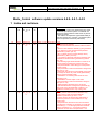
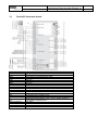
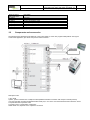
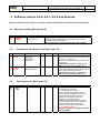
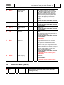
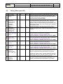
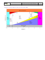
ELECTRONIC REGULATION
SERVICE MANUAL
MODUCONTROL
•
•
•
SOFTWARE VERSION SW 4.4 date 26/01/2012
SOFTWARE VERSION SW 4.4.1 date 26/06/2012
SOFTWARE VERSION SW 4.4.2 date 18/09/2012
EN
Service manual
Edition 1.5
Pag. 1/14
Technical specification Modu_control
ANR ANL ANLI ANF ANK SRP SRA WRL CL
Date 18 September 2012
Author SAT
Service manual
Edition 1.5
Pag. 2/14
Technical specification Modu_control
ANR ANL ANLI ANF ANK SRP SRA WRL CL
Date 18 September 2012
Author SAT
Modu_Control software update versions 4.4.0- 4.4.1- 4.4.2
1 Index and revisions
17
34164 02900 im 00 34163. mc43_0.s19
.00
pan1_0_1.s1
20
9
13-06-2011 Version 4.3.0
- Control WRL cooling only (water/water unit). Read
condenser input sensor in place of condenser coil
sensor and read condenser outlet sensor in place of
outdoor air sensor.
- The outdoor air temperature (optional Kit KSAE) is
read from sensor 25°C 10 kOhm connected in place
of the low pressure transducer (ratiometric).
18
34164 02900 im 00 34163. mc44_0.s19
.00
pan1_0_1.s1
20
9
19
34164 02900 im 00 34163. mc44_1.s19
.00
pan1_0_1.s1
20
9
26-01-2012 4.4.0
- Management of ANLI021,
ANLI026,ANLI040ANLI045,ANLI071,ANLI075,ANLI0
80
- Maximum time between defrosting cycle (parameter
(Y) in reference to the air exthernal temperature
(parameter (U) Menu psw 72).
- BP Low alarm never in bypass (always active)
(parameter (L) Menu psw 125)
- Low pressure value that change the discharge gas
temperature threshold alarm (parameter (n) Menu
psw 125)
- New discharge gas threshold alarm in reference to
the low pressure (parameter (o) Menu psw 125)
- New parameteter to select the type of compressor
(inverter Carel).
- New parameter to select the maximum voltage from
DCP (for CL unit)
- NO2 Carel uPC electronic board digital output used
to manage the three way water valve (plant/sanitary
tank) to produce sanitary water
- Visualization of remaining time before the next
defrosting cycle
- Visualization of DCP output in volt value
- New parameter to select the maximum voltage to
DCP (for CL unit)
- Sliding setpoint calculation every 30 minuts
- Optional transducers management: parameter (u)
Menu psw 125. If this parameter is setted 1, are
enable the transducers into only cooling units
26-06-2012 4.4.1
Solved problem with transducers absent in only
cooling units in case are present disturbs.
Addition of parameter (Y) menu = 125.
From this version are present two parameters to
control the presence of the transducers on only
cooling units.
If are present the transducers into the units where
normally aren’t provided, is necessary to modify the
parameter (U) = 1 for the high pressure transducer
and the parameter (Y) = 1 for the low pressure
transducer into the menu with password = 125.
Service manual
Edition 1.5
20
34164
.00
02900 im 00 34163. mc44_2.s19
pan1_0_1.s1
20
9
Pag. 3/14
Technical specification Modu_control
ANR ANL ANLI ANF ANK SRP SRA WRL CL
Date 18 September 2012
Author SAT
18-09-2012 4.4.2
Modified the maximum deltaP during the startup to
3.0 bar.
Bypass of low pressure and low pressure LOW (1.6
bar) during defrosting cycle and after 3 min from the
end (time parameter to bypass the low pressure).
Bypass initialization of the defrost threshold of low
pressure for 3 minutes (time parameter bypass the
low pressure) after the end of the inversion cycle.
Now the threshold of low pressure that forces the
defrost cycle by inversing cycle, does not wait the
minimum time between two reversals.
Insert of software Version 1.0B47 for Carel uPC in
case of ANLI units.
Service manual
Edition 1.5
Pag. 4/14
Technical specification Modu_control
ANR ANL ANLI ANF ANK SRP SRA WRL CL
Date 18 September 2012
Author SAT
2 Introduction
The Moducontrol electronics was introduced in 2006, to need to control the new range of air-water chillers ANL
series with refrigerant R410A and also to have a new electronic controller designed and produced by Aermec.
Since then this controller has been used on two compressor units and the ANZ (high performance heat pump unit
with R407C, sometimes accompanied with accessories like supplementary electric heating and soft start) that were
call ANR
Then the control logic for inverter units was added, known as ANLI and the condensing version ANL-C, moreover
the control logic was added for ANK units and next to last for the water-water series WRL cooling only (software
version 4.3).
The last update software version 4.4.0, 4.4.1 and 4.4.2 of this electronic is born in particular for the ANLI
new inverter Carel series and for some managements of new CL (new air-water chiller with centrifugal fan
unit); moreover to optimize other things already present in the precedent versions.
The control logic of the Moducontrol board is practically the same for the ANL,ANR, ANLI, ANF,
ANK, SRP SRA and for the WRL (water-water cooling only) series.
This document shows only the parameters relating to the control of the units ANLI new inverter
Carel series and other managements described above, then only the relevant new parameters
and features were introduced, as listed in the following paragraphs.
For the complete document of the Moducontrol electronic controller please refer to the specific
control manual ANL version 4.1.
About the particular value of parameters and dip-switches settings, check the Software
Configuration in reference to the type of unit.
Service manual
Edition 1.5
Pag. 5/14
Technical specification Modu_control
ANR ANL ANLI ANF ANK SRP SRA WRL CL
Date 18 September 2012
Author SAT
3 ANLI inverter CAREL logic
Aermec Moducontrol board: It is
the main board that contains the
algorithms to control the unit.
It manage the safety controls and
the defrosting cycles
RS485 bus
comunication from
Moducontrol and
Carel µPC:
With this
comunication, the
Moducontrol board
reads the pressure
and temperature
values, the EEV and
compressor status
from the Carel µPC
board. Then the
Moducontrol transfer
the the signals to
Carel µPC in function
of the power
requested from the
thermostat.
Carel µPC
board:. With the
bus RS485, it
manage the
communication
with the inverter
module Power
Plus and manage
the EEV
electronic
expansion valve.
It contains the
algorithms to
protect the
compressor and
operation limits.
Carel Inverter
Power Plus: It
manages and
controls the
compressor,
check the
electrical
parameters of the
compressor.
(current, voltage
and rotor speed)
Service manual
Edition 1.5
3.1
Pag. 6/14
Technical specification Modu_control
ANR ANL ANLI ANF ANK SRP SRA WRL CL
Date 18 September 2012
Author SAT
Carel µPC electronic board
DIGITAL Outputs
NO1
NO2
NO3
NO4
NO5
NO6
NO7
DIGITAL Input
ID1
ID2
ID3
ID4
ID5
ID6
ID7
ANALOG Outputs
Y1 (0-10V)
Y2 (0-10V)
Y3 (0-10V)
Carel µPC small
Description
Not used
3way sanitary valve (plant/sanitary tank)
Not used
Not used
Not used
Not used
General alarm
Description
Not used
Not used
Not used
Compressor Start/Stop (with ramp)
Compressor shut off (without ramp)
Not used
Serial comunication selection: Open = pLAN., Closed= Modbus to
comunication with Moducontrol
Description
Not used
Not used
Not used
Service manual
Edition 1.5
ANALOG Inputs
Max length 30m
B1 (NTC)
B2 (NTC)
B3 (NTC)
B4 (NTC)
B5 (NTC; 4-20 mA)
B6 (NTC)
B7 (NTC)
3.2
Pag. 7/14
Technical specification Modu_control
ANR ANL ANLI ANF ANK SRP SRA WRL CL
Date 18 September 2012
Author SAT
Description
Not used
Not used
Suction temperature probe
Discharge temperature probe- Carel HT probe
Not used
Low pressure transducer – Ratiometric transducer 0 - 5V / 0 -17.3 bar
High pressure transducer – Ratiometric transducer 0 - 5V / 0 – 50 bar
Components and accessories
The following figure illustrates the architecture of the system made up of the uPC programmable platform running the
Combo Drive application, plus all the components and accessories.
Description Code
1 μPC Small
2 pDG1, panel or wall-mounted + telephone cable (disabled if Modbus connection with 3rd part controller present)
3 3rd part controller provided with RS485 Modbus serial port, in our case is connected the Moducontrol electronic board.
4 Unipolar electronic expansion valve
5 Inverter Power+ to drive BLDC compressors
6 BMS serial card, depends on the supervisor connected
Pag. 8/14
Technical specification Modu_control
ANR ANL ANLI ANF ANK SRP SRA WRL CL
Date 18 September 2012
Author SAT
Service manual
Edition 1.5
4 Software version 4.4.0- 4.4.1- 4.4.2 new features
With the software versions 4.4.0, 4.4.1 and 4.4.2 some new features were introduced as listed below:
4.1
N
6
4.2
N
Advanced reading Menu (pwd 10)
Description
ASP
Name
Suction temperature
probe value (°C)
Meaning
Temperature value reading from the suction compressor probe.
Parameter visualized only with inverter CAREL (see the 2nd
Compressor Menu parameter 0).
Specific parameter for the ANLI units with inverter CAREL.
Compressor and Water Pump Menu (pwd 72)
U t dF
Name
Defrosting cycle
extensive
temperature
threshold
Min
Default
-30.0 -30.0
Max
10.0
y t d2
Extended time
between defrosts
0
120
4.3
N
Description
90
Meaning
Outside air temperature below which uses a
maximum time between defrost cycles longer.
See the next parameter.
Below the -4°C the humidity contains into the
air decrease.
Actually this parameter is used for the
ANLI units with inverter CAREL only.
Maximum time interval between defrost cycles
if the outside air temperature is lower than the
value of the parameter (U) above.
Actually this parameter is used for the
ANLI units with inverter CAREL only.
2nd Compressor Menu (pwd 73)
Description
0 I nU
Name
Inverter type
Min
0
Default
0
Max
2
Meaning
Type of inverter used:
0- Inverter type Longertek.
1- Inverter type APY . Having
inverter APY the frequencies setted on
menu compressor (password 72) are the
frequencies generated from inverter
modul. The frequencies showed on
readings menu parameter(P) e
parameter(q) are the frequence (rpm per
second) of compressor. These are 1/3 of
frequencies generated from inverter
modul. (from software version SW3.9).
2 – Inverter type Carel,
Specific parameter for the ANLI units with
inverter CAREL.
Pag. 9/14
Technical specification Modu_control
ANR ANL ANLI ANF ANK SRP SRA WRL CL
Date 18 September 2012
Author SAT
Service manual
Edition 1.5
3 BdC
Baudrate
0
comunication with
inverter Carel
0
1
4 SHC
Superheating
1.0
setpoint in cooling
mode
4.0
15.0
5 SHH
Superheating
1.0
setpoint in heating
mode
7.0
15.0
6 CPt
Type of
compressor
0
2
0
7 SAL
Set-point inverter
frequency to
“jump” over
0
0
120
8 BSA
“Jump over”
0
inverter frequency
band
0
100
4.4
N
4
0 – Bauderate setted to 38400 to comunicate
with serial 0 of Carel µPC control board.
1 - Bauderate setted to 9600 to comunicate
with serial 1 of BMS expansion board. It is
utilized to connect the PGD1 control panel
when is necessary check the system with a
particular diagnostic (disconnect the wire
bridge on ID7 digital input of Carel uPC
electronic board to utilize the control panel
PGD1).
Specific parameter for the ANLI units with
inverter CAREL.
Superheating setpoint calculate by EEV in
cooling mode
Specific parameter for the ANLI units with
inverter CAREL.
Superheating setpoint calculate by EEV in
heating mode
Specific parameter for the ANLI units with
inverter CAREL.
Type of compressor combined with inverter
Carel.
This parameter influenced the parameters of
the inverter Carel directly.
Specific parameter for the ANLI units with
inverter CAREL.
Is necessary contact the factory before
modifications
The inverter will stop work in the frequencies
range setted between this set + the band
“jump over” frequency (next parameter).
This parameter and the next, are used to
eliminate (“jump over”) frequencies that after
our test in factory could be generate
vibrations (in reference to the type and size of
unit where it is installed) and consequently
could be cause breakage of some critical
points in the refrigerant system.
Specific parameter for the ANLI units with
inverter CAREL.
Is necessary contact the factory before
modifications
Frequency band refering the precedent
parameter.
Specific parameter for the ANLI units with
inverter CAREL.
Is necessary contact the factory before
modifications
Maintenance Menu 2 (pwd 84)
Name
Maximum Volt
DCP
Min
2.0
Default
9.9
Max
Meaning
9.9
Maximum voltage to control the DCP or inverter fan.
Used in particular for CL units (new air-water chiller with
centrifugal fan unit)
Pag. 10/14
Technical specification Modu_control
ANR ANL ANLI ANF ANK SRP SRA WRL CL
Date 18 September 2012
Author SAT
Service manual
Edition 1.5
4.5
N
L
n
o
P
Factory Menu (pwd 125)
Name
Low pressure
threshold limit
(LOW)
Min
0
Threshold low
0
pressure to
change the high
compressor
discharge
temperature
alarm
Discharge
80.0
temperature
threshold alarm
refering to the
parameter (n)
Discharge
80.0
temperature limit
zone 1a
Default
1.6
Max
10.0
0
10.0
112.0
145.0
112.0
145.0
q
Discharge
temperature
alarm zone 1a
80.0
118.0
145.0
r
Discharge
80.0
temperature limit
zone 1b
112.0
145.0
t
Discharge
temperature
alarm 1b
80.0
118.0
145.0
U
High pressure
transducer
present on the
only cooling unit.
0
0
1
y
Optional low
pressure
transducer
presence
0
0
1
Meaning
Threshold of low pressure limit. This threshold is never bypassed
during the compressor start. Below this threshold, the unit is
considered discharge (without or lower presence)of refrigerant
gas, the compressor start is inhibited.
This limit put in off the system directly.
- If the low pressure is equal or less than this threshold, is used
the following discharge gas temperature alarm, parameter (o).
- If the low pressure reading is greater than this threshold
parameter, will be use (6) like discharge gas temperature alarm.
- With setting 0 value is only active parameter (6) as discharge
gas temperature alarm.
Remind parameter (6): Discharge gas temperature alarm (°C)
Discharge temperature value that replace the value on the
parameter (6) into this menu, refering to the parameter (n) into
this menu.
Threshold temperature of the discharge compressor gas over
which are reduced the speed of the compressor.
See the compressor envelope diagram below.
Specific parameter for the ANLI units with inverter CAREL.
Threshold temperature of the discharge compressor gas over
which the high-temperature discharge gas alarm is generated.
See the compressor envelope diagram below.
Specific parameter for the ANLI units with inverter CAREL.
Threshold temperature of the discharge compressor gas over
which are reduced the speed of the compressor.
See the compressor envelope diagram below.
Specific parameter for the ANLI units with inverter CAREL.
Threshold temperature of the discharge compressor gas over
which the high-temperature discharge gas alarm is generated.
See the compressor envelope diagram below.
Specific parameter for the ANLI units with inverter CAREL.
1= Presence of transducer into only cooling units.
More than to manage the low and high pressure alarms, it is
manage the transducers alarms like broken or not present.
Compared to software version 4.4.0 this parameter changes of
meaning and refers only to the high pressure transducer. The
next parameter is refer to the low pressure transducer.
1= Presence of optional transducer into only cooling units.
More than to manage the low and high pressure alarms, it is
manage the transducers alarms like broken or not present.
Service manual
Edition 1.5
4.6
Pag. 11/14
Technical specification Modu_control
ANR ANL ANLI ANF ANK SRP SRA WRL CL
Date 18 September 2012
Author SAT
Maintenance reading Menu (pwd 334)
This menu contains further informations about the unit functions over the informations present into the
Reading Menu.
N
Description
Name
Output in voltage (V) to
control the DCP
Meaning
Voltage otput from Moducontrol electronic board to manage the
DCP, refer to the refrigerant high pressure and outdoor temperature
measures.
0
dCP
1
SBr
Countdown defrosting
cycle time
Remaning time of next defrosting cycle. It is visualized in minutes.
The -1 value indicate that is suspend or no active causes by outdoor
temperature or condenser temperature values.
2
Sur
Superheating
Superheating value calculate by the EEV expansion valve.
See the parameter (0) into the 2nd Compressor Menu.
Specific parameter for the ANLI units with inverter CAREL.
3
UAL
Electronic expansion
valve opening
percentage
Electroni expansion valve opening in percentage.
See the parameter (0) into the 2nd Compressor Menu.
Specific parameter for the ANLI units with inverter CAREL.
4
St P
Electronic expansion
valve opening in steps
Electronic expansion valve opening in steps
See the parameter (0) into the 2nd Compressor Menu.
Specific parameter for the ANLI units with inverter CAREL.
5
I nU
Compressor envelope
zone
6
CPP
Motor power
Zones meaning: 0= Null; 1= OK; 2= Max. comp. ratio;
3= Max.disch. press.; 4= High curr.; 5= Max.suct. press.; 6= Min.
comp. ratio; 7= Low Delta press.; 8= Min. disch. press.; 9= Min.
suct. press.
See the compressor envelope diagram below.
See the parameter (0) into the 2nd Compressor Menu.
Specific parameter for the ANLI units with inverter CAREL.
Electric power of motor (KW) measured by inverter
See the parameter (0) into the 2nd Compressor Menu.
Specific parameter for the ANLI units with inverter CAREL.
7
CPS
Rotor speed of
compressor
Rotor speed of compressor in rpm
See the parameter (0) into the 2nd Compressor Menu.
Specific parameter for the ANLI units with inverter CAREL.
Service manual
Edition 1.5
Pag. 12/14
Technical specification Modu_control
ANR ANL ANLI ANF ANK SRP SRA WRL CL
Date 18 September 2012
Author SAT
Compressor envelope diagram for ANLI units with inverter CAREL
Service manual
Edition 1.5
Pag. 13/14
Technical specification Modu_control
ANR ANL ANLI ANF ANK SRP SRA WRL CL
Date 18 September 2012
Author SAT
5 Regulation
5.1
Kind of Defrost
SOFTWARE 4.4.0 NEWS:
From the 4.4.0 software version for the new ANLI inverter sizes ANLI021, ANLI026, ANLI040, ANLI045, ANLI071,
ANLI075, ANLI080, it is introduced an exthenal air temperature threshold that permit to extend the defrosting cycle in
case to have low humidity conditions (low exthernal air temperature). The exthernal air temperature threshold is possible
setted on the parameter (U) into the Compressor and Water Pump Menu (pwd 72), the interval time between the
defrosting cycle in case the exthernal air temperature is below this threshold, it is possible setted on the parameter (y)
still in the same Compressor and Water Pump Menu (pwd 72).
6 Alarms
6.1
New alarms for ANLI with Inverter Carel
Alarm
code
61
62
63
64
65
66
67
68
69
70
71
72
73
74
75
76
Prealarm
code
161
162
163
164
165
166
167
168
169
170
171
172
173
174
175
176
77
78
79
80
81
82
177
178
179
180
181
182
83
84
85
86
87
88
89
90
91
92
93
94
183
184
185
186
187
188
189
190
191
192
193
194
Meaning
Overcurrent (Inverter Carel)
Compressor overload (Inverter Carel)
Overvoltage (Inverter Carel)
Undervoltage (Inverter Carel)
Drive overtemperature (Inverter Carel)
Drive undertemperature (Inverter Carel)
Hardware overcurrent (Inverter Carel)
Compressor overtemperature (Inverter Carel)
Reserved (Inverter Carel)
CPU error (Inverter Carel)
Default parameters (Inverter Carel)
DC bus ripple. (Inverter Carel)
Comunication between Inverter and Carel uPC electronic board absent (Inverter Carel error)
Temperature drive sensor broken (Inverter Carel)
Autoconfiguration failed (Inverter Carel)
Drive inverter enabled (Inverter Carel). Check the wire bridge on the Inverter Power Plus
terminal
Motor phases error (Inverter Carel)
Cooling fan of Inverter broken (Inverter Carel)
Speed fault (Inverter Carel). Check the type of compressor setted
PFC fault (appear if the PFC is enable but the DC bus voltage is very lower)
PFC overload trip (this alarm will not present with new software firmware)
Input voltage error (appear when the power supply go down below 170 volt when the
compressor running)
Generic inverter error (Inverter Carel)
B1 probe broken (Carel uPC electronic board)
B2 probe broken (Carel uPC electronic board)
B3 probe broken (Carel uPC electronic board)
B4 probe broken (Carel uPC electronic board)
B5 probe broken (Carel uPC electronic board)
B6 probe broken (Carel uPC electronic board)
B7 probe broken (Carel uPC electronic board)
High pressure alarm (Carel uPC electronic board)
Low pressure alarm (Carel uPC electronic board)
High discharge gas temperature alarm (Carel uPC electronic board)
High-Low differential pressure lower respect the minimum requested (0,3 bar in 60sec) (Carel
uPC electronic board)
Service manual
Edition 1.5
Alarm
code
95
96
97
98
99
200
201
202
203
204
Prealarm
code
195
196
197
198
199
300
301
302
303
304
205
206
207
305
306
307
Pag. 14/14
Technical specification Modu_control
ANR ANL ANLI ANF ANK SRP SRA WRL CL
Date 18 September 2012
Author SAT
Meaning
Compressor starting failed (Carel uPC electronic board)
Exceed time of operative limits alarm (Carel uPC electronic board)
Low Super Heat alarm (Carel uPC electronic board)
MOP alarm (Carel uPC electronic board)
Low suction temperature alarm (Carel uPC electronic board)
EVD EVO evotunes alarm (Carel uPC electronic board)
EVD EVO regulation alarm (Carel uPC electronic board)
EVD EVO system alarms probe errors (Carel uPC electronic board)
Reserved (Carel uPC electronic board)
Comunication between Inverter and Carel uPC electronic board absent (Errore Carel uPC
electronic board)
Inverter model not compatible with the compressor selected (Carel uPC electronic board)
Start fail due to high DeltaP (default = 20bar) (Carel uPC electronic board
Low pressure limit. Unit discharge of refrigerant gas
AERMEC S.p.A.
37040 Bevilacqua (VR) Italy–Via Roma, 996
Tel. (+39) 0442 633111
Telefax 0442 93730–(+39) 0442 93566
www.aermec.com - [email protected]
The technical data on the following documents are not binding.
Aermec reserves the right to make any changes at any time deemed necessary for product improvement.