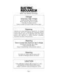
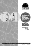
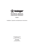
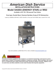
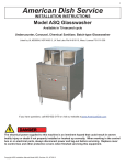
1
TECHNICAL MANUAL
For
DOOR TYPE DISHWASHING MACHINE
Commander 18-5
Commander 18-5C
Commander 18-5H
Commander 18-5CH
Installation, Operation, and Maintenance Instructions
Insinger Machine Company
6245 State Road
Philadelphia, PA 19135-2996
800.344.4802
Fax 215.624.6966
www.insingermachine.com
Thank you for purchasing this quality
Insinger product.
On the space provided below please record the
model, serial number and start-up date of this unit:
Model:__________________________________
Serial Number:___________________________
Start-Up Date:____________________________
When referring to this equipment please have this
information available.
Each piece of equipment at Insinger is carefully
tested before shipment for proper operation. If the
need for service should arise please contact your
local Authorized Insinger Service Company.
TABLE OF CONTENTS
Part 1
Technical Information
• Catalog Cut-sheet
• Introduction
• Warranty
Part 2
Installation Instructions
• Installation Drawing
Part 3
Operating Instructions
• Operation and Cleaning Instructions
• Maintenance and Repair Procedures
• Basic Service Guide
Part 4
Electrical Schematics & Replacement Parts
A Service Network Listing is provided on our web
site, www.insingermachine.com or call Insinger at
800-344-4802 for your local authorized servicer.
• Machine Wiring Diagrams
• Control Panel Layout and Component Drawing
For proper activation of the Insinger Limited
Warranty a SureFire™ Start-Up & Check-Out
Service should be completed on your machine.
Refer to the Introduction section in this manual for
an explanation of Insinger SureFire™ Start-Up &
Check-Out Program.
Part 5
Replacement Parts
• General Assembly Drawing for:
Commander 18-5, 18-5H,
Commander 18-5C,
• Drain Assembly
• Motor Assembly, 1HP
• Pump, Motor & Suction Assembly
• Level Float Installation
• Electric Heater, Diode and Level float
• Steam Injectors, Steam Coils and Steam
Booster Assembly’s
• Final Rinse Assembly
• Final Rinse Assembly (self-contained booster)
• Electric Booster Assembly
• Self Contained Booster Assembly
Please read the Insinger Limited Warranty and all
installation and operation instructions carefully
before attempting to install or operate your new
Insinger product.
To register your machine for warranty by phone,
fax or the internet or for answers to question
concerning installation, operation, or service
contact our Technical Services Department:
1-13
14-17
18
19
20-22
TECHNICAL SERVICE CONTACTS
Toll-Free 800-344-4802
Fax
215-624-6966
E-mail
[email protected]
Web
www.insingermachine.com
Door Type Series DOC COM 1.0 06
www.insingermachine.com 800-344-4802
Door Type Series DOC COM 1.0 06
1
www.insingermachine.com 800-344-4802
Door Type Series DOC COM 1.0 06
2
www.insingermachine.com 800-344-4802
Door Type Series DOC COM 1.0 06
3
www.insingermachine.com 800-344-4802
Door Type Series DOC COM 1.0 06
4
www.insingermachine.com 800-344-4802
PART 1
TECHNICAL INFORMATION
Commander 18-5 Series
INTRODUCTION
NSF 3-2003 requirements for detergent
and chemical sanitizer dispensers.
Purpose
The purpose of this technical manual is to provide
installation, operation, cleaning and maintenance
directions.
This machine must be operated with an automatic
detergent dispenser and, if applicable, an automatic
chemical sanitizer feeder, including a visual means
to verify that detergents and sanitizers are delivered or a visual or audible alarm to signal if detergents and sanitizers are not available for delivery to
the respective washing and sanitizing systems.
Please see instructions for electrical and plumbing
connections located in this manual and in the
feeder equipment manual.
A section is provided for replacement parts.
Scope
This manual contains all pertinent information to
assist in the proper installation, operation, cleaning,
maintenance, and parts ordering for Commander
18-5 series dishwashers.
The installation instructions are intended for
qualified equipment installers. The operation and
cleaning instructions are intended for the daily
users of the equipment. The maintenance and
parts sections are intended for qualified service
and/or maintenance technicians. Replacement
parts may be ordered directly from our factory
or from your local Insinger Authorized Service
Agency. You can speak to the Insinger Technical
Services Department, 800/344-4802, or e-mail us
at [email protected]. When calling
for warranty information or replacement parts
please provide the model and serial number of your
Insinger Equipment. These important numbers
should be noted in this manual on the spaces
provided on the opening page.
Definitions
Throughout this guide you will find the following
terms: WARNING, CAUTION, & NOTE.
WARNING indicates potential physical danger.
CAUTION indicates potential equipment damage.
NOTE indicates helpful operating hints or tips.
You will visually be able to identify each as
shown below:
!
Surefire™ Start-up & Check-out Program
Insinger is proud to offer our exclusive Surefire™
Start-up & Check-out Program to our commercial
customers. This service is included in the purchase
price of your new Insinger dishwasher. We will
provide an authorized factory service technician for
the initial start-up of your new Insinger dishwasher
to ensure it is running at optimum levels from the
very first pass. Please call the factory or your local
Insinger Sales Representative to schedule this
service.
þ
WARNING:
Indicates potential physical danger.
NOTE:
Indicates helpful operating hints or tips.
CAUTION:
Indicates potential equipment damage.
Door Type Series DOC COM 1.0 06
5
www.insingermachine.com 800-344-4802
PART 1
TECHNICAL INFORMATION
Door Type Dishwashing Machine
Safety Summary
The following are general safety precautions that
are not related to any specific procedures. These
are recommended precautions that personnel must
understand and apply during many phases of operation and maintenance.
Keep Away From Live Circuits
Operating personnel must at all times observe all
safety regulations. Do not replace components or
make adjustments inside the equipment with the
high voltage supply turned on. Under certain conditions, dangerous potentials may exist when the
power control is in the off position. To avoid casualties, always remove power, red tag machine and
ground a circuit before touching it.
Do Not Service or Adjust Alone
Under no circumstances should any person reach
into or enter the enclosure for the purpose of servicing or adjusting the equipment except in the
presence of someone who is capable of rendering
aid.
Resuscitation
Personnel working with or near high voltages
should be familiar with modern methods of resuscitation. Such information may be obtained from the
Bureau of Medicine and Surgery.
Door Type Series DOC COM 1.0 06
6
www.insingermachine.com 800-344-4802
PART 1
TECHNICAL INFORMATION
INSINGER MACHINE COMPANY LIMITED WARRANTY
Insinger Machine Company, Inc. (Insinger) hereby
warrants to the original retail purchaser of this
Insinger Machine Company, Inc. product, that if it
is assembled and operated in accordance with the
printed instructions accompanying it, then for a
period of either 15 months from the date of
shipment from Insinger or 1 year (12 months) from
the date of installation, that said Insinger product
shall be free from defects in material and workmanship. Whichever one of the two aforestated limited
warranty time periods is the longest shall be the
applicable limited warranty coverage time period.
the instruction booklet (operating instructions) or
for improper operation or failure to follow normal
operating instructions (as set out in the instruction
booklet). Insinger is not responsible nor liable for
any conditions of erosion or corrosion caused by
corrosive detergents, acids, lye or other chemicals
used in the washing and or cleaning process.
Service must be done by either Insinger Appointed
Service Agencies or agencies receiving prior
authorization from Insinger.
All warranty work must be done during normal
working hours, unless purchaser receives prior
authorization from Insinger.
Insinger may require reasonable proof of your date
of purchase; therefore, you should retain your copy
of invoice or shipping document.
There are no other express warrants except as set
forth herein and any applicable implied warranties
of merchantability and fitness are limited in
duration to the period of coverage of this express
written limited warranty. This limited warranty
supersedes all other express warranties, implied
warranties of merchant-ability and fitness or
limited warranties as of this date, January 1, 1998.
Some states do not allow limitation on how long
an implied warranty lasts so this limitation may
not apply to you.
This limited warranty shall be limited to the repair
or replacement of parts which prove defective under
normal use and service and which on examination
shall indicate, to Insinger’s satisfaction, they are
defective. Any part that is claimed to be defective
and covered by this limited warranty must be
returned to Insinger, this may be done through an
Authorized Service Agency. Furnish serial number
of machine with shipment and send to:
Insinger Machine Company
6245 State Road
Philadelphia, PA 19135-2996
If Insinger’s inspection confirms the defect and the
claim, Insinger will repair or replace such part
without charge and return it to you freight or postage prepaid.
Insinger is not liable for any special, indirect or
consequential damages. Some states do not allow
the exclusion or limitation of incidental or consequential damages, so this limitation nor exclusion
may not apply to you.
This limited warranty does not cover any failure or
accident, abuse, misuse, alteration, misapplication,
improper installation, fire, flood, acts of God or
improper maintenance or service, or failure to perform normal and routine maintenance as set out in
Insinger does not authorize any person or company
to assume for it any other obligation or liability in
connection with the sale, installation, use, removal,
return or replacement of its equipment: and no such
representations are binding on Insinger.
Door Type Series DOC COM 1.0 06
7
www.insingermachine.com 800-344-4802
PART 1
TECHNICAL INFORMATION
INSINGER MACHINE COMPANY LIMITED WARRANTY
COMMERCIAL MARINE USE
Insinger Machine Company, Inc. (Insinger) hereby
warrants to the original retail purchaser of this
Insinger Machine Company, Inc. product, that if it
is assembled and operated in accordance with the
printed instructions accompanying it (installation
manual), then for a period of 18 months from the
date of installation on board the vessel, that said
Insinger product shall be free from defects in
material and workmanship.
Labor will be billed to the customer at a reduced
rate of $40.00 per hour. If sailing with a vessel is
required, then an eight hour per day minimum will
apply.
This limited warranty does not cover accident,
abuse, misuse, alteration, misapplication, improper
installation, fire, flood, or improper maintenance or
service, or failure to perform normal and routine
maintenance as set out in the instruction booklet
(operating instructions) or for improper operation
or failure to follow normal operating instructions
(as set out in the instruction booklet).
Insinger may require reasonable proof of your date
of equipment install, therefore, you should retain
your copy of invoice or shipping document.
This limited warranty shall be limited to the
replacement of parts which prove defective under
normal use and service and which on examination
shall indicate, to Insinger's satisfaction, they are
defective. Any part that is claimed to be defective
and covered by this limited warranty must be
returned to Insinger. Furnish serial number of
machine with shipment and send to:
Insinger is not responsible nor liable for any conditions of erosion or corrosion caused by corrosive
detergents, acids, lye or other chemicals used in the
washing, caring and or cleaning process.
Insinger Machine Company, Inc.
6245 State Road
Philadelphia, PA 19135-2996
There are no other express warrants except as set
forth herein and any applicable implied warranties
of merchantability and fitness are limited in duration to the period of coverage of this express written
limited warranty. This limited warranty supersedes
all other express warranties, implied warranties of
merchantability and fitness or limited warranties as
the above date.
Warranty service must be done by either Insinger
Appointed Service Agencies or agencies, customers
galley engineers receiving prior authorization from
Insinger.
If Insinger's inspection confirms the defect and the
claim, Insinger will repair or replace such part
without charge and return it to you freight or postage prepaid. If part damages are not covered,
Insinger will contact the customer and advise.
Insinger does not authorize any person or company
locally or overseas to assume for it any other
obligation or liability in connection with the sale,
installation, use, removal, return or replacement of
its equipment; and no such representations are
binding on Insinger.
If a factory trained authorized technician is
required to repair or replace defective parts or material during the 18 month warranty period, the
cruise line will be responsible for the payment of
travel expense and a minimum of four hours labor.
Door Type Series DOC COM 1.0 06
8
www.insingermachine.com 800-344-4802
PART 2
INSTALLATION INSTRUCTIONS
Commander 18-5 Series & CS Series
INSTALLATION INSTRUCTIONS
A single-point electrical connection is provided for
the pumps, control circuit, and wash tank heater.
If an electric booster is provided, connect power
directly to the booster.
Placement
Carefully uncrate machine. Take caution not to
damage components which may be mounted on
the top or sides of the machine. Set unit in place
and adjust the feet to level the machine.
If the Insinger Self-Contained booster is provided
the machine comes standard with a Single-Point
Connection (to include the booster).
Fasten the tables to the load and unload side of the
machine. Most installations require fastening the
turn-down lip of the dish tables to the side of the
machine with flathead countersunk screws. The
table design should provide horizontal clearance of
30” for servicing.
CAUTION:
Connections must be made to a circuit breaker
or fused disconnect as provided by the
end-user and required by local codes.
A laminated wiring diagram is inside the control panel.
Electrical Connections
Connect electrical lines sized for the correct
voltage, current and phase of the machine. These
should agree with the machine requirements
indicated on the nameplate and labels on the control panel.
Fuse Sizing Chart
208VAC/3È
230VAC/3È
380VAC/3È
460VAC/3È
220VAC/1È
18-5(C)
steam heat
6A
6A
6A
6A
15A
18-5(C)
electric heat
15A
15A
10A
10A
30A
18-5(C)
electric heat
Insinger SCB
60A
50A
35A
25A
100A
18-5H
steam heat
15A
10A
6A
6A
25A
18-5H
electric heat
25A
25A
15A
15A
45A
18-5H
electric heat
Insinger SCB
70A
60A
40A
30A
110A
Model
Door Type Series DOC COM 1.0 06
9
www.insingermachine.com 800-344-4802
PART 2
INSTALLATION INSTRUCTIONS
Chemicals
Upon the completed installation of the dishwasher,
contact a local detergent/chemical supplier for
the correct chemicals for your soil load and
geographical area.
CAUTION:
As with any 3 phase system, an electrician must check
all motors for proper phasing, i.e., Pump motors must be
running in direction indicated by arrow on housing.
Electrical connection points for the detergent
dispenser and rinse injector are located inside the
control panel. Refer to the wiring diagram for this
machine for the proper connection points.
Mechanical Connections
Connect 140º water lines for tank fill/booster as
tagged and noted on the installation drawings. If
machine is provided with steam heat connect the
steam lines and steam condensate lines as tagged
and noted on installation drawings. Connect the
drain line.
Dispensers may be connected on either the
primary voltage side of the machine or the 24VAC
control voltage side.
CAUTION:
CAUTION:
Drain lines must be as specified on installation
drawings.
When connecting on the 24VAC control voltage side of
the transformer, total VA must not exceed 50VA.
Drain line should be properly vented and should have
fall of not less than 1/4” to the foot of proper flow.
Some area plumbing codes require drains
to flow into an open gap with an opening twice
the diameter of the pipe.
The detergent density probe should be installed in
the hole provided & labeled in the wash tank.
A switch on the control panel labeled “Wash Cycle”
is provided for de-liming the machine. When
activated, this switch will keep the machine in an
indefinite wash cycle. This feature can also be used
to wash heavily soiled ware on an extended wash
cycle.
Check with your local plumbing codes for the type of
drain connection required.
CAUTION:
Tabling
Load and unload tables should be pitched towards
the machine to return excess water into the
machine.
All lines must be flushed prior to use to remove debris.
CAUTION:
Insinger dishmachines are user-friendly, making
them easy to operate and maintain. By following
the operation procedure and general cleaning procedures your Insinger dishwasher will give you
years of trouble free service.
Do not reduce the size of lines as specified in installation
drawings. All Lines are sized to facilitate necessary
flows, pressures, etc.
HVAC
Ventilation system must be sized to provide adequate ventilation per machine specs. Refer to spec
sheet.
Door Type Series DOC COM 1.0 06
10
www.insingermachine.com 800-344-4802
PART 2
Door Type Series DOC COM 1.0 06
11
INSTALLATION INSTRUCTIONS
www.insingermachine.com 800-344-4802
PART 2
Door Type Series DOC COM 1.0 06
12
INSTALLATION INSTRUCTIONS
www.insingermachine.com 800-344-4802
PART 2
Door Type Series DOC COM 1.0 06
13
INSTALLATION INSTRUCTIONS
www.insingermachine.com 800-344-4802
PART 2
Door Type Series DOC COM 1.0 06
14
INSTALLATION INSTRUCTIONS
www.insingermachine.com 800-344-4802
PART 3 OPERATION & CLEANING INSTRUCTIONS
Insinger dishmachines are user-friendly, making
them the easiest dishmachines on the market to
operate and maintain.
WARNING:
!
By following these operating procedures your
Insinger dishwasher will give you years of trouble
free service.
OPERATION INSTRUCTIONS
1. Ensure drain overflow tube is in place. Close all
tank drain valves. One drain is provided for
each tank of the dishmachine.
9. Open doors and remove rack of clean ware.
For continuous operation repeat steps 2B19 &
2B10
2. Check for proper installation and cleanliness of
all internal, removable components such as
suction strainers, scrap screens, and spray
manifolds.
10. Upon completion of ware cleaning move the
power toggle switch to the “OFF” position.
11. Refer to the cleaning procedures for proper
clean-up of the dishmachine.
3. Ensure all water & steam lines are open.
Ensure electrical circuits are on.
12. A switch on the control panel labeled “Wash
Cycle” is provided for use when de-liming the
machine. When activated, this switch will keep
the machine in an indefinite wash cycle. This
feature can also be used to wash heavily soiled
ware on an extended wash cycle.
4. Close machine doors.
5. Move the power toggle switch to the ON position. The machine will fill the tank, run through a
complete wash/rinse cycle and shut-off.
6. When the tanks are full the tank heat will operate automatically. Proper wash tank temperature is 156ºF minimum. Proper final rinse temperature is 180ºF minimum at 20 PSI, while in
the final rinse cycle.
13. Report any unusual occurrences to qualified
service personnel.
The following cleaning procedures should be
done daily, at the end of the shift.
Cleaning Procedures, Daily
CAUTION:
1. Remove all internal removable parts including
spray manifolds, scrap screens, drain overflow
tube and suction strainer.
To ensure proper operation
of the auto tank fill feature and the tank heaters,
the tank level floats MUST be cleaned daily.
2. Remove the end caps from the spray manifolds
and clean with the brush provided. Flush the
manifolds.
7. Open doors.
8. Insert a rack of soiled dishware in machine and
lower doors. Depress the cycle start button,
machine will wash and rinse automatically.
When the rinse indicator light goes off the machine cycle is complete
3. Flush scrap screens
4. Clean drain overflow tube.
þ
CAUTION:
Overloading racks will minimize the
proper cleaning of ware.
Door Type Series DOC COM 1.0 06
Do not open the doors during the wash/
rinse cycle as hot water is being sprayed.
An interlock is provided to stop the wash/
rinse cycle if the doors are opened but hot
water may spray out if doors are opened
too quickly.
15
NOTE:
V-cup seal on the drain overflow tube may
become gummed not allowing the overflow
tube to seal. This will cause the drain to leak
water. Remove any build-up on the V-cup
seal. When the seal becomes worn, replace
with part # D2-557.
www.insingermachine.com 800-344-4802
PART 3 OPERATION & CLEANING INSTRUCTIONS
CLEANING PROCEDURES (CONTINUED)
PRESSURE ADJUSTMENT
5. Clean suction strainers of build-up.
Pressure in the final rinse must be maintained at 20
± 2 psi. Adjustment of the pressure is made with
the adjusting screw on the pressure reducing valve.
þ
NOTE:
Improper cleaning of the suction strainers
will cause the pumps to cavitate. This will
cause poor washing results.
6. Clean the tank level float with a plastic abrasive
pad (do not use steel wool).
CAUTION:
Level floats must be cleaned daily.
Build-up of grease and dirt will cause faulty operation
of the tank fill heating system.
þ
If there are flow or pressure problems with the
pressure reducing valve, CAREFULLY remove the
strainer assembly and clean the strainer screen.
Be careful not to damage the Hex nut o-ring
NOTE:
Upper & lower wash & rinse pipes are
not the same.
7. Final rinse nozzles should be cleaned of matter
clogging the jet spray.
8. A door should be left open to allow drying of
interior surfaces.
Door Type Series DOC COM 1.0 06
16
www.insingermachine.com 800-344-4802
PART 3
MAINTENANCE & REPAIR PROCEDURES
The following is a basic guide for the repair and
replacement of common dishwasher parts. Refer to
the Basic Services Guide for troubleshooting tips.
2. Remove cap on top of the coil. Remove the
coil.
3. Remove the 4 hex bolts and lift bonnet from
valve body. Note positioning of spring and
plunger.
MAINTENANCE REQUIREMENTS
Daily
1. Refer to the operations and cleaning instructions provided in this manual for daily cleaning
procedures.
4. Remove main piston.
5. Inspect for dirt, wear or lime build-up. Clean or
replace as required.
6. Reassemble in reverse of disassembly.
Weekly
1. The entire machine should be wiped down
using an industrial grade stainless steel
cleaner.
HEX NUT
2. Under the supervision of your detergent
supplier the machine interior must be properly
de-limed.
þ
STRAINER
SCREEN
NOTE:
The water quality in some areas requires
de-liming to be done more frequently.
Contact your detergent supplier for
recommended de-liming frequency.
LINE STRAINER
Liner Strainer Disassembly
1. Shut off water or steam supply.
Quarterly
1. Remove and clean the strainer screens on the
water and steam lines. If the screens cannot be
cleaned, replace.
2. Remove large hex nut on bottom of strainer
body.
2. Inspect the condition of the solenoid valve
seats, and diaphragms. Replace where necessary.
3. Remove strainer screen. Inspect and clean or
replace as necessary.
4. Reassemble in reverse of disassembly. Water
flow must be same direction as arrow on line
strainer body. Use new gaskets to insure a tight
seal.
3. Inspect drain O-Rings for leakage. Replace
where necessary.
4. Check door spring tension and adjust where
necessary.
Pump Disassembly
1. Before disassembling pump ensure there are
no obstructions in the pump intake. Remove
and clean the suction strainer (inside tank). See
dwg. SK-2456 & SK-2923
5. Check wash and rinse hub bushing/bearing and
replace where necessary.
MAINTENANCE PROCEDURES
Solenoid Valve Disassembly
(See dwg. SK-4692)
1. Disconnect the power supply to the machine.
Turn off the water supply.
Door Type Series DOC COM 1.0 06
þ
17
NOTE:
It is not necessary to remove the pump
housing from the machine to disassemble
www.insingermachine.com 800-344-4802
PART 3
MAINTENANCE & REPAIR PROCEDURES
Pump Disassembly (Continued)
2. Remove the pump motor and impeller by
removing the 4 hex bolts attaching them to the
pump housing.
3. Repair or replace the pump parts as required.
4. Reassemble in reverse of disassembly.
Immersion Heater Replacement
See dwg. #SK-4703
1. The immersion heater MUST be completely
submerged at all times. If this is not the case
contact a qualified service technician. The
heated surface should never be in contact with
sludge. See dwg. SK-4703.
2. Remove the housing covering the wiring terminations. Disconnect the immersion heater
wires.
3. Remove the immersion heater by loosening
and removing the large hex nut.
þ
NOTE:
Troubleshooting Tank Temperatures
Use plumbers putty as gasketing around
the immersion heater to minimize leaks.
Electric Heat
1. If temperature does not change check the temperature control board (P/N DE9-251) proper
operation. If the temperature control board is
faulty, replace.
Tank Heat Temperature Adjustment
1. A temperature control board is provided in the
control panel for easy adjustment of tank temperature. Though tank temperature is adjusted
during the machines factory test it is sometimes
necessary to re-adjust the temperature at startup.
2. Verify tank heat contactor is working correctly.
If not, replace.
3. Verify all immersion heaters are working properly and not limed. If not, replace.
2. Locate the temperature control board. Use the
control panel layout drawing located in Section
4, Electrical Schematic and Replacement Parts.
Steam Heat
1. If temperature does not change check the temperature control board (P/N DE9-251) proper
operation. If the temperature control board is
faulty, replace.
3. Adjust the tank temperature to the desired temperature by turning the potentiometer located
on the temperature control board. An arrow on
the potentiometer indicates increase.
2. Verify steam pressure per machine specifications.
4. If the temperature does not change refer to
Troubleshooting Tank Temperatures in the
next section.
Door Type Series DOC COM 1.0 06
3. Verify steam trap is not clogged. If so, replace.
18
www.insingermachine.com 800-344-4802
PART 3
MAINTENANCE & REPAIR PROCEDURES
Motor Overloads
All motors used on Insinger Machines are provided
with motor overloads. Motor overloads are adjusted
when the machines are factory tested. Should it be
necessary to adjust the motor overloads in the field
first verify the motor current draw for the voltage
the machine is using.
Level System
The level control system consists of one overfill
timer (P/N DE7-35) and one level float (P/N DEF60) per tank.
Using the Control Panel Component Layout Dwg.
located in Section 3 to identify the overload adjust
by turning the dial to the appropriate AMP draw.
When the level float is actuated, the overfill timer
begins to time-out and continues the filling process
until the tank(s) is full.
When the system is powered-up, the tank(s) will
begin to fill (assuming no water is in the tanks).
Liquid Level Timer DE7-35
Sk-4698
þ
þ
Door Type Series DOC COM 1.0 06
19
NOTE:
The overfill timer MUST be adjusted during
initial start-up. Adjustment depends on water fill pressure. The water level MUST be
1/4” below the lip of the overflow tube. Adjust by increasing or decreasing the potentiometer on the level timer.
NOTE:
Dirty level floats will cause the tank heat to
energize with no water in the tanks.
LEVEL FLOATS MUST BE CLEANED
DAILY.
www.insingermachine.com 800-344-4802
PART 3
MAINTENANCE & REPAIR PROCEDURES
Cycle Timers
The board labeled with a ‘W” is for the wash cycle,
the ‘R’ represents the rinse cycle, and the ‘L’
stands for the dwell cycle – the time at the end of
the wash cycle where the amber light is on for a
few seconds to ensure the dishes are sanitized and
to prevent dishmachine operators from getting
splashed with water still flinging off the wash and
rinse arms at the end of the cycle. Do not open the
machine before the light goes out.
If your machine is controlled by timing boards instead
of a PLC, timing boards are used to determine wash
time, rinse time and dwell time.
See drawing SK-3490, item no. 8. The potentiometer
control – see below – increases or decreases the
sequence time. Turn the potentiometer with a small
slotted screwdriver clockwise to increase time and
counterclockwise to decrease time.
Door Type Series DOC COM 1.0 06
20
www.insingermachine.com 800-344-4802
PART 3
Door Type Series DOC COM 1.0 06
MAINTENANCE & REPAIR PROCEDURES
21
www.insingermachine.com 800-344-4802
PART 3
Door Type Series DOC COM 1.0 06
MAINTENANCE & REPAIR PROCEDURES
22
www.insingermachine.com 800-344-4802
PART 3
Door Type Series DOC COM 1.0 06
MAINTENANCE & REPAIR PROCEDURES
23
www.insingermachine.com 800-344-4802
PART 3
Door Type Series DOC COM 1.0 06
MAINTENANCE & REPAIR PROCEDURES
24
www.insingermachine.com 800-344-4802
PART 4
Door Type Series DOC COM 1.0 06
25
ELECTRICAL SCHEMATICS
& REPLACEMENT PARTS
www.insingermachine.com 800-344-4802
PART 4
Door Type Series DOC COM 1.0 06
26
ELECTRICAL SCHEMATICS
& REPLACEMENT PARTS
www.insingermachine.com 800-344-4802
PART 4
Door Type Series DOC COM 1.0 06
27
ELECTRICAL SCHEMATICS
& REPLACEMENT PARTS
www.insingermachine.com 800-344-4802
PART 4
Door Type Series DOC COM 1.0 06
28
ELECTRICAL SCHEMATICS
& REPLACEMENT PARTS
www.insingermachine.com 800-344-4802
PART 4
Door Type Series DOC COM 1.0 06
29
ELECTRICAL SCHEMATICS
& REPLACEMENT PARTS
www.insingermachine.com 800-344-4802
PART 4
Door Type Series DOC COM 1.0 06
30
ELECTRICAL SCHEMATICS
& REPLACEMENT PARTS
www.insingermachine.com 800-344-4802
PART 4
Door Type Series DOC COM 1.0 06
31
ELECTRICAL SCHEMATICS
& REPLACEMENT PARTS
www.insingermachine.com 800-344-4802
PART 4
Door Type Series DOC COM 1.0 06
32
ELECTRICAL SCHEMATICS
& REPLACEMENT PARTS
www.insingermachine.com 800-344-4802
PART 4
Door Type Series DOC COM 1.0 06
33
ELECTRICAL SCHEMATICS
& REPLACEMENT PARTS
www.insingermachine.com 800-344-4802
PART 5 REPLACEMENT PARTS
Door Type Series DOC COM 1.0 06
34
www.insingermachine.com 800-344-4802
PART 5 REPLACEMENT PARTS
Door Type Series DOC COM 1.0 06
35
www.insingermachine.com 800-344-4802
PART 5 REPLACEMENT PARTS
Door Type Series DOC COM 1.0 06
36
www.insingermachine.com 800-344-4802
PART 5 REPLACEMENT PARTS
Door Type Series DOC COM 1.0 06
37
www.insingermachine.com 800-344-4802
PART 5 REPLACEMENT PARTS
Door Type Series DOC COM 1.0 06
38
www.insingermachine.com 800-344-4802
PART 5 REPLACEMENT PARTS
Door Type Series DOC COM 1.0 06
39
www.insingermachine.com 800-344-4802
PART 5 REPLACEMENT PARTS
Door Type Series DOC COM 1.0 06
40
www.insingermachine.com 800-344-4802
PART 5 REPLACEMENT PARTS
Door Type Series DOC COM 1.0 06
41
www.insingermachine.com 800-344-4802
PART 5 REPLACEMENT PARTS
Door Type Series DOC COM 1.0 06
42
www.insingermachine.com 800-344-4802
PART 5 REPLACEMENT PARTS
Door Type Series DOC COM 1.0 06
43
www.insingermachine.com 800-344-4802
PART 5 REPLACEMENT PARTS
Door Type Series DOC COM 1.0 06
44
www.insingermachine.com 800-344-4802
PART 5 REPLACEMENT PARTS
Door Type Series DOC COM 1.0 06
45
www.insingermachine.com 800-344-4802
PART 5 REPLACEMENT PARTS
Door Type Series DOC COM 1.0 06
46
www.insingermachine.com 800-344-4802
PART 5 REPLACEMENT PARTS
Door Type Series DOC COM 1.0 06
47
www.insingermachine.com 800-344-4802
PART 5 REPLACEMENT PARTS
Door Type Series DOC COM 1.0 06
48
www.insingermachine.com 800-344-4802
PART 5 REPLACEMENT PARTS
Door Type Series DOC COM 1.0 06
49
www.insingermachine.com 800-344-4802
PART 5 REPLACEMENT PARTS
Door Type Series DOC COM 1.0 06
50
www.insingermachine.com 800-344-4802
PART 5 REPLACEMENT PARTS
Door Type Series DOC COM 1.0 06
51
www.insingermachine.com 800-344-4802
PART 5 REPLACEMENT PARTS
Door Type Series DOC COM 1.0 06
52
www.insingermachine.com 800-344-4802
6245 State Road
Philadelphia, PA 19135-2996
800.344.4802
Fax 215.624.6966
www.insingermachine.com