1
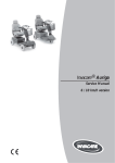
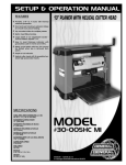
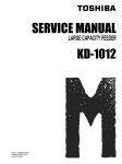
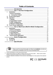
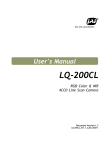
Invacare® Auriga
Service Manual
9
Maintenance and repair
9.1.
Chassis
9.1.1 Front wheel frame (3-wheeler)
Note:
When servicing the chassis, if deformations or faulty welding seams are found, then the complete chassis
should be replaced.
1.39
1.30
1.41
1.38
1.1
1.37
1.35
1.32
1.23
1.2
1.23
1.01
1.45
Pos
Qty
Part-No.
Part Description
1,1
1,01
1,2
1,23
1,30
1,32
1,35
1,37
1,38
1,39
1,41
1,45
1
1
1
1
1
2
1
1
1
1
2
1
1421011
1421012
1421013
1421014
1421015
1421016
1421017
1421019
1421020
1421024
1421027
1421029
FRONT FRAME ASSY., (3 WHEELER)
FRONT FRAME, (3 WHEELER)
FRONT BUMPER ASS’Y.,3W
FORK BEARING SET,
8 PCS/SET
SUPPORTING BRACKET, REAR SHROUD
SPACER, FRONT FRAME AND REAR FRAME ASSEMBLY
ASSEMBLY HOOK, FRAME, 3W/4W
ASSEMBLY LEVER, FRAME
BLACK TIP
PIN WITH TIE, RD. 8x50L
BATTERY STRAP, 50x660L
MAIN LOOM, FRAME,
3W/4W
Page 15
Invacare® Auriga
Service Manual
9.1.2 Front wheel frame (4-wheeler)
1.37
1.38
1.39
1.35
1.30
1.45
1.41
1.32
1.01
1.23
1.2
1.1
1.10
1.23
1.25
1.03
1.43
1.26
1.09
1.3
1.2
1.04
1.4
Pos
Qty
Part-No.
Part Description
1,1
1,01
1,2
1,03
1,04
1,09
1,10
1,3
1,4
1,23
1,25
1,26
1,30
1,32
1,35
1,37
1,38
1,39
1,41
1,43
1,45
1
1
1
2
4
1
1
1
1
1
2
1
1
2
1
1
1
1
2
1
1
1421031
1421030
1421032
1421033
1421034
1421035
1421036
1421037
1421038
1421014
1421040
1421241
1421015
1421016
1421017
1421019
1421020
1421024
1421027
1421249
1421029
FRONT FRAME ASS’Y.,(4 WHEELER)
FRONT FRAME ONLY, 4W
FRONT SUSPENSION SYSTEM, 4W
BUFFER, RUBBER BUSHING
BALL BEARING, STEM
FRONT AXLE SET, LH
FRONT AXLE SET, RH
CONNECTING ROD SET, LONG RD. 10 X 350 L
CONNECTING ROD SET, RD. 10 X 150 L, SHORT
FORK BEARING SET, 8 PCS/SET
BUFFER, RUBBER BLOCK, M10 X 30 L
FRONT BUMPER, 4W
SUPPORTING BRACKET, REAR SHROUD
SPACER, FRONT FRAME AND REAR FRAME ASSY
ASSEMBLY HOOK, FRAME, 3W/4W
ASSEMBLY LEVER, FRAME
BLACK TIP
PIN WITH TIE, RD. 8 X 50 L
BATTERY STRAP, 50 X 660 L
STEERING PEDESTAL ASS’Y.
MAIN LOOM, FRAME, 3W/4W
Page 16
Invacare® Auriga
Service Manual
9.1.3 Rear frame assembly (3+4-wheelers)
1.53
1.5
1.66
1.49
1.6
1.48
1.5
Pos
Qty
Part-No.
Part Description
1,48
1,49
1,53
1,5
1,6
1,66
1
1
1
2
1
1
1421251
1426314
1421253
1421254
1421255
1421256
REAR FRAME ONLY, 3W/4W
SHOCK ABSORBERS
MOUNTING CLAMP, TRANSAXLE
ANTI-TIPPER WHEEL ASS’Y
RELEASE LEVER ASS’Y., TRANSAXLE, 3W/4W
MOUNTING BASE
Page 17
Invacare® Auriga
9.2
Service Manual
Drive Unit
6.01
6.02
Pos
Qty
Part-No.
Part Description
6,01
6,02
1
2
1416109
1421275
TRANSAXLE ASS’Y., M33D
CARBON BRUSH
Page 18
Invacare® Auriga
Service Manual
9.2.1 Replacing the drive unit
•
•
•
Remove the seat and the rear shroud (see chapter 9.3.5).
Pull the de-clutching lever and jack up the vehicle.
Remove the screw that connects the release lever
to the drive unit.
•
Loosen the bolts that hold the wheels and
remove them, if necessary using a special tool to
remove wheels (see notes on page 24).
•
•
Release the clamps that hold the drive unit.
Disconnect the cable that connects the drive unit
and the electronic system, and remove the drive unit.
Reassembly is done in reverse order.
6.01
6.02
9.2.2 Replacing the carbon brushes
•
•
•
•
Remove the seat and the rear shroud (see chapter 9.3.5).
Remove the spray guard of the charger.
Remove all four screws on the charger
and remove the charger.
Remove both plastic screws from the drive unit
and replace the brushes.
Reassembly is done in reverse order.
Page 19
Invacare® Auriga
9.3
Service Manual
Shroud
9.3.1 Front shroud (3-wheeler)
2.05
2.1
2.03
Pos
Qty
Part-No.
Part Description
2,1
2,1
2,03
2,05
1
1
2
1
1421257
1421258
1421259
1421260
FRONT SHROUD ASS’Y., RUBY RED, 3W
FRONT SHROUD ASS’Y., SAPPHIRE BLUE, 3W
SIDE TRIM, 16 X 640 L
CARPET, GREY, 3W
Page 20
Invacare® Auriga
Service Manual
9.3.2 Front shroud (4-wheeler)
2.05
2.06
2.06
2.1
2.03
Pos
Qty
Part-No.
Part Description
2,1
2,1
2,03
2,05
2,06
1
1
2
1
2
1421261
1421262
1421263
1421264
1421265
FRONT SHROUD ASS’Y., RUBY RED, 4W
FRONT SHROUD ASS’Y., SAPPHIRE BLUE, 4W
SIDE BUMPER, 25 X 380 L
MAIN CARPET, GREY, 4W
SMALL CARPET, GREY, 4W
Page 21
Invacare® Auriga
Service Manual
9.3.3 Rear shroud (3+4-wheelers)
2.2
2.12
2.13
2.14
2.20
2.28
RE
CA
A
NV
I
2.18
2.17
Pos
Qty
Part-No.
Part Description
2,2
2,2
2,12
2,13
2,14
2,17
2,18
2,20
2,21
2,28
1
1
1
1
1
2
2
2
1
1
1421266
1421267
1421268
1421269
1421270
1421271
1421272
1421273
1426324
1421274
REAR SHROUD ASS’Y.,RUBY RED, 3W/4W
REAR SHROUD ASS’Y.,SAPPHIRE BLUE, 3W/4W
RUBBER BOOT, SEAT POST
CAP, CHARGER SOCKET
WIRE OF CHARGER PLUG
SIDE RUBBER PAD, 25 X 125 L
REFLECTOR, YELLOW
REAR LAMP / LH
REAR LAMP / RH
TAIL/INDICATOR LIGHT CONNECTING WIRE
Page 22
Invacare® Auriga
Service Manual
9.3.4 Removing and re-fitting the front shroud (3+4-wheelers)
•
•
•
•
Remove the seat and the rear shroud (see chapter 9.3.5).
•
Remove the steering column by turning and pulling
it upwards.
•
•
Remove all four screws under the foot mat.
Tilt the steering column towards the rear.
Roll up the rubber sleeve.
Loosen and remove the clamping lever, and
disconnect the cable.
Carefully detach the front shroud from the velcro strips,
and remove by pulling upwards.
Reassembly is done in reverse order.
9.3.5 Removing and re-fitting the rear shroud
Note:
When removing the rear shroud, first detach the velcro fasteners on the sides, then pull the shroud up and
off. When re-fitting the shroud, first position both of the openings for the seat post and the de-clutching lever.
Then fit the two tabs on the front of the shroud into the corresponding slots, push the shroud down, and
firmly press the velcro fasteners together.
•
•
Pull the lever that releases the seat.
Rotate the seat a quarter of a revolution in either direction
and remove the seat.
•
Carefully release the rear shroud from the velcro
fasteners.
•
Disconnect the cables that go to the lighting system and
the on-board charger, and remove the rear shroud.
Reassembly is done in reverse order.
Page 23
Invacare® Auriga
9.4.
Service Manual
Wheels
Note:
When replacing worn or damaged wheels and / or tyres, you may need to use special tools, such as a wheel
removal tool, or let the work be performed by an authorised dealer.
9.4.1 Front wheel assembly (3-wheeler)
5.05
5.07
5.06
5.02
5.1
5.01
Pos
Qty
Part-No.
Part Description
5,1
5,01
5,02
5,05
5,06
5,07
1
1
1
1
1
2
1421276
1421277
1421278
1421279
1421280
1421281
FRONT WHEEL ASS’Y., 3.00-4 (260 X 85)
TYRE, 3.00-4
INNER TUBE, 3.00-4
FORK, 10” WHEEL
HUB, FRONT WHEEL
PRECISION BEARING, 6003 ZZ
Page 24
Invacare® Auriga
Service Manual
9.4.2 Front wheel assembly (4-wheeler)
5.2
5.21
5.22
Pos
Qty
Part-No.
Part Description
5,2
5,21
5,22
2
1
1
1421284
1421277
1421283
REAR WHEEL ASS’Y., 3.00-4, W/INVACARE LOGO
TYRE, 3.00-4
INNER TUBE ONLY, 3.00-4
9.4.3 Rear wheel assembly (3+4-wheelers)
5.04
5.1
5.01
5.02
Pos
Qty
Part-No.
Part Description
5,1
5,01
5,02
5,04
2
1
1
2
1421282
1421277
1421283
1421281
FRONT WHEEL ASS’Y., 3.00-4, W/INVACARE LOGO
TYRE, 3.00-4
INNER TUBE ONLY, 3.00-4
PRECISION BEARING, 6003 ZZ
Page 25
Invacare® Auriga
Service Manual
Caution:
Either jack up the vehicle, and use appropriate supports (such as blocks of wood) to prop it up, or tilt
it over on its side. Make sure the front wheel(s) can revolve freely. Secure the vehicle against sliding or
falling over. Danger of injury!
9.5 Assembling / disassembling the front wheel (3-wheeler)
•
Pull the de-clutching lever, jack up the vehicle, and
remove both bolts, which hold the wheel.
•
Remove the wheel from the fork.
Reassembly is done in reverse order.
9.5.1 Assembling / disassembling the front fork (3-wheeler)
•
•
•
•
•
Remove the seat and the rear shroud (see chapter 9.3.5).
Remove the steering column (see chapter 9.3.4).
Remove front shroud (see chapter 9.3.4).
Remove the eight-sided nut, the metal Gusset,
and the second eight-sided nut underneath it.
Lift the crash guard and pull the fork down and out.
Reassembly is done in reverse order.
9.5.2 Replacing the bearings (3-wheeler)
•
•
•
•
•
•
Remove the seat and the rear shroud (see chapter 9.3.5).
Remove the steering column (see chapter 9.3.4).
Remove the front shroud (see chapter 9.3.4).
Remove the eight-sided nut, the metal Gusset,
and the second eight-sided nut underneath it.
Lift the crash guard and pull the fork down and out.
Pull the fork down and out, and replace the bearings.
Reassembly is done in reverse order.
Page 26
Invacare® Auriga
Service Manual
9.6 Assembling / disassembling the front wheel (4-wheeler)
•
•
Pull the de-clutching lever and jack up the vehicle.
Remove the nut and the washer underneath it,
and remove the front wheel.
Reassembly is done in reverse order.
9.6.1 Assembling / disassembling the front suspension (4-wheeler)
•
•
Remove the seat and the rear shroud (see chapter 9.3.5).
Remove the steering column and the front shroud (see
Chapter 9.3.4).
•
•
Pull the de-clutching lever and jack up the vehicle.
•
•
Pull the front wheel suspension out towards the front.
•
Remove the front wheel (see above).
Remove the Allen screws and the nuts of the
front wheel suspension from the chassis.
Remove both steering rods from the front wheel suspension.
Reassembly is done in reverse order.
9.6.2 Replacing the bearings (4-wheeler)
•
•
Remove the seat and the rear shroud (see chapter 9.3.5).
Remove the steering column and the front shroud (see
Chapter 9.3.4).
•
•
Pull the de-clutching lever and jack up the vehicle.
•
•
•
Pull the front wheel suspension out towards the front.
Remove the Allen screws and the nuts of the
front wheel suspension from the chassis.
Remove the connecting nut and gusset
Pull the fork down and out, and replace the bearings.
Reassembly is done in reverse order.
Page 27
Invacare® Auriga
Service Manual
9.6.3 Assembling / disassembling the steering column tube (4-wheeler)
•
•
Remove the seat and the rear shroud (see chapter 9.3.5).
Remove the steering column and the front shroud (see
Chapter 9.3.4).
•
•
Pull the de-clutching lever and jack up the vehicle.
•
•
•
Pull the front wheel suspension out towards the front.
Remove the Allen screws and the nuts of the
front wheel suspension from the chassis.
Remove the connecting nut and gusset
Remove the steering column tube from the steering rods.
Reassembly is done in reverse order.
9.6.4 Assembling / disassembling the rear wheels (3+4-wheelers)
•
•
Pull the de-clutching lever and jack up the vehicle.
Remove the nut in the centre of the wheel, and
pull off the rear wheel, you may need
to use a special wheel removal tool (see notes on p.24).
Reassembly is done in reverse order.
Page 28
Invacare® Auriga
9.7.
Service Manual
Electronic system
Caution:
Be careful not to short-circuit the battery poles with a tool!
Take into account the heavy weight of the batteries!
Danger of injury!
9.7.1 Batteries, electronic system, charger and connections
6.26
6.27
6.16
6.24
6.28
6.13
6.21
6.22
6.23
6.15
6.11
POS
Qty
Part-No.
Part Description
6,11
6,13
6,15
6,16
6,21
6,22
6,23
6,24
6,26
6,26
6,27
6,28
1
1
1
1
1
1
1
1
2
2
2
2
1421606
1421607
1421608
1421609
1421610
1421611
1421612
1421613
P50029
PG50988
1421614
1421615
CONTROLLER, RHINO DS72K01
ELECTRONIC COVER
CHARGER, ON-BOARD, HAMPTON 24V/3A OB7
WATERPROOF COVER
MAIN LOOM, CONTROLLER
WIRE CONNECTING, MOTOR/CONTROLLER
CONNECTING WIRE, POWER SEAT
WIRE CONNECTING, CONTROLLER
BATTERY 12V / 31 AH
BATTERY MK 12V / 40 AH
WIRE CONNECTING WITH 40A FUSE, BATTERY
FUSE, 60A
Page 29
Invacare® Auriga
Service Manual
9.7.2 Replacing the charger
•
•
Remove the seat and the rear shroud (see chapter 9.3.5).
•
Remove all four screws and the charger.
Disconnect the cable that goes from the electronics to the
charger, and remove the charger spray guard.
Reassembly is done in reverse order.
Note:
Make sure that both batteries are charged (24V), if necessary, charge them completely. Check the charge
levels of both batteries individually!
9.7.3 Replacing the batteries
•
•
•
Remove the seat and the rear shroud (see chapter 9.3.5).
Remove the battery cable (C) from the electronics.
Open the belts that hold the batteries and remove the
batteries.
•
Disconnect the battery cable contacts from the
batteries.
•
After replacing with new or charged batteries, re-connect
the contacts of the battery cables to the batteries.
Make sure to connect the cables to the correct poles!
Reassembly is done in reverse order.
9.7.4 Replacing the electronics
•
•
Remove the seat and the rear shroud (see chapter 9.3.5).
•
•
Remove all four screws from the charger shroud.
•
•
Remove the electronics box (see above).
Remove the battery cables (C), the main cable
loom (A) of the steering column, and the drive unit
cable (B) from the electronic system
Remove the 8, 6 and 4 pronged plugs from the electronic
system.
Remove all three screws and take out the electronics.
Reassembly is done in reverse order.
Page 30
Invacare® Auriga
Service Manual
9.7.5 Replacing a fuse
•
•
Remove the seat and the rear shroud (see chapter 9.3.5).
Open the fuse holder on the battery cable and replace the
fuse.
Reassembly is done in reverse order.
9.7.6 Hand-held programmer
•
The hand-held programmer serves to diagnose faults,
and to adjust driving parameters.
•
The set consists of the hand-held programmer and an
adapter cable.
•
For more information on programming and fault
diagnosis, please use the hand-held programmer’s User
Guide.
Part # 1421661
Page 31
Invacare® Auriga
9.8
Service Manual
Tiller linking assembly / control panel
9.8.1 Steering column
4.72
4.67
4.7
4.65
4.51
4.8
4.73
4.8
4.6
4.71
Pos
Qty
Part-No.
Part Description
4,6
4,51
4,7
4,7
4,8
4,8
4,65
4,67
4,71
4,72
4,73
1
1
1
1
1
1
1
2
1
1
1
1421039
1421242
1421243
1421244
1421245
1421246
1421247
1421248
1421250
1421616
1426337
TILLER LINKING MECH. ASS’Y., 3W/840
HEIGHT ADJ. LOCK MECH., 230L
REAR TILLER SHROUD SET, CANDY APPLE RED, 3W/4W
REAR TILLER SHROUD SET, BLUE, 3W/4W
FRONT TILLER SHROUD SET, CANDY APPLE RED, 3W/4W
FRONT TILLER SHROUD SET, BLUE, 3W/4W
KEY SWITCH W/CONNECTING WIRE, 3W/4W
MOUNTING BASKET SPCC 2.5 T
LOWER RUBBER BOOT
BASKET, WIRE MESH
SET COLLAR
Page 32
Invacare® Auriga
Service Manual
9.8.2 Tiller
4.1
4.28
4.38
4.3
4.03
4.05
4.04
4.21
4.02
4.23
4.42
4.17
4.43
4.2
4.45
4.5
4.07
4.08
4.06
4.02
4.34
4.37
4.36
4.4
4.2
Pos
4.1
4,1
4,02
4,03
4,04
4,05
4,06
Qty
1
1
2
1
1
1
1
Part-No.
1421619
1421619
1421620
1421621
1421622
1421623
1421624
Part Description
TILLER ASS’Y RED, 3W/4W
TILLER ASS’Y., BLUE, 3W/4W
FOAM SLEEVE, RD. 30 X 20 X 355 L
LEVER BRAKE, LH
CABLE CASING, 450L, LONG
WIRE, RD. 1.5 X 540 L
STOPPER
Page 33
Invacare® Auriga
Service Manual
Pos.
Qty
Part-No.
Part Description
4,07
4,08
4,2
4,17
4,21
4,23
4,3
4,3
4,28
4,34
4,4
4,4
4,37
4,38
4,38
4,5
4,42
4,43
4,45
1
1
1
1
1
1
1
1
1
1
1
1
1
1
1
1
2
1
1
1421625
1421626
1421627
1421628
1421629
1421630
1421631
1421632
1421633
1421634
1421635
1421636
1421637
1421638
1421639
1421640
1421641
1421642
1421643
SCREW, M5 X 8 L
ALUM. WIRE END CAP
THROTTLE ASS’Y., 3W/4W
POTENTIOMETER
CONNECTING WIRE, POT
CONNECTING WIRE, SPEED POT
UPPER DASH BOARD SET, CANDY APPLE RED, 3W/4W
UPPER DASH BOARD SET, BLUE, 3W/4W
TOUCH PANEL, KEYPAD, 3W/4W
MAIN LOOM, TILLER, 3W
LOWER DASH BOARD SET, CANDY APPLE RED, 3W/4W
LOWER DASH BOARD SET, BLUE, 3W/4W
CHARGER SOCKET WITH WIRE
BACK MIRROR, RH
BACK MIRROR, LH
HEAD LIGHT WITH WIRE ASS’Y.
BULB, 24V/5W, INDICATOR LIGHT
BULB, 24V/18W
CONNECTING WIRE, HEAD LIGHT
9.9 Replacing the keypad and the control panel
•
Remove the plastic caps from the screws on the left
and right sides on top of the control panel, remove the
screws, and disconnect the circuit board.
•
•
•
Remove the control panel.
•
Lift the 2-ply keypad on one corner with a flat tool
and pull it off.
•
Remove any remnants of adhesive left over after
removing the foil.
Remove the cap from the knob and remove the knob.
Remove the control circuit board and disconnect and
remove the keypad.
Reassembly is done in reverse order.
9.9.1 Assembling / disassembling the steering column shroud
•
•
•
•
Remove the screws that hold the basket.
Remove the screws from the steering column shroud.
Remove the control panel (see above).
Disconnect the key switch with its cable from the
control circuit board, and remove the shroud.
Reassembly is done in reverse order.
Page 34
Invacare® Auriga
Service Manual
9.9.2 Replacing the Bowden cable
•
•
Remove the rear shroud from the steering column.
•
Remove the screw on the steering column completely
pull out the Bowden cable.
Remove the screw at the end of the Bowden
cable from the stopper, and pull the Bowden cable out.
Reassembly is done in reverse order.
9.9.3 Replacing the throttle lever
•
•
•
Remove the control panel (see chapter 9.9).
Remove the screws from the potentiometer.
Remove the Allen screws on both sides and
pull the throttle lever down and out.
Reassembly is done in reverse order.
9.9.4 Replacing the potentiometer
•
•
•
Remove the control panel (see chapter 9.9)
Remove the screw from the potentiometer.
Loosen the Allen screws on the side and pull the
potentiometer up and out.
•
Remove some of the insulation material from the wires that
are connected to the potentiometer, and use a soldering
iron to melt the soldered connections.
•
•
Remove the spring, the nut and the washer.
Fit the new potentiometer and centre it (see notes below).
Reassembly is done in reverse order.
Note:
When fitting a new potentiometer, it is of upmost importance to make sure the potentiometer, as well as
the throttle lever are correctly centred. Danger of accidents! The potentiometer has a standard value of
approximately 5 kOhm. Check the potentiometer with a digital multimeter to make sure that it returns exactly
the same value from the right and left connections to the neutral centre position.
Page 35
Invacare® Auriga
Service Manual
9.9.5 Replacing the light bulbs in the front
•
•
Remove the control panel (see chapter 9.9).
•
•
Tilt the head light upwards and take it out.
Remove the screw that holds the head light, located
underneath the lens (see fig. 9.9.7).
Remove the fixture with the bulb from the rear of the
head light by twisting and pulling it out. Replace the bulb.
Reassembly is done in reverse order.
9.9.6 Replacing the light bulbs in the rear
•
•
Remove the seat and the rear shroud (see chapter 9.3.5).
Remove the light fixture from the inside of the rear shroud
by twisting it, and replace the bulb.
Reassembly is done in reverse order.
9.9.7 Replacing the head light
•
•
Remove the control panel (see chapter 9.9).
•
Tilt the head light upwards and take it out. Remove the
light fixture from the rear of the head light.
Remove the screw that holds the head light, located
underneath the lens (see fig. 9.9.7).
Reassembly is done in reverse order.
Page 36