1
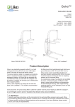
Likorall 242
Instruction Guide
English
7EN120108-02
2008-11-20
Applies to the following models:
Likorall 242 ES
Prod. No. 3122005-3122006
Likorall 242 ES R2R
Prod. No. 3122007-3122008
Likorall 242 S
Prod. No. 3122009-3122010
Likorall 242 S R2R
Prod. No. 3122011-3122012
Likorall 242 ES
Likorall 242 ES R2R
Product Description
Likorall is a stationary lift, often referred to as an
"overhead lift". Likorall is mounted on Liko's rail systems, which are adapted to the room(s) they are to
be used in. The rail system can be built as a Straight
rail, with or without curves, a Traverse system or a
Room-to-room system. Liko's rail systems consist of
hundreds of components and each part is specifically
selected so that every installation is adapted to the
room(s) they are to be installed in. The rail system
can be either a stationary installation or a freestanding
installation, such as the FreeSpan.
Likorall must be installed by authorized personnel and
in accordance with installation instructions provided by
Liko.
Likorall is intended for lifting and transferring patients;
e.g., from the bed to the wheelchair; to and from the
floor; for visits to the lavatory and bath; for walking,
standing, gait and balance training; for weighing, and
for lifting in combination with a stretcher.
The Likorall R2R model (room-to-room) enables transfer of patients between two independent overhead rail
systems in separate rooms and without the need for
openings above doorways.
Model 242 ES is prepared for wireless handcontrol (IR).
Likorall 242 ES can also be equipped with a Transfer
Motor, which facilitates motorized transfer along the
rail.
A large, comprehensive range of accessories including different types of lift slings in a variety of sizes and
models is available for Likorall.
In this document, the person being lifted is referred to as the ”patient” and the person helping them is referred to as
the ”caregiver”.
is a warning triangle used for situations that demand extra care and attention.
IMPORTANT!
Read instructions for the lift and accessories carefully before use. Lifting and transferring a person always
presents a potential risk. A thorough understanding of the contents of instruction guides is essential. Only
trained personnel should use the equipment. If you have questions, please contact Liko or your local Liko
representative.
Contents
Safety Instructions .............................................................................................. 2
Technical Data .................................................................................................... 3
Definitions............................................................................................................ 3
Assembly............................................................................................................. 4
Operation..........................................................................................................5-6
Charging the Batteries . ...................................................................................... 7
Room-to-room Transfers with Likorall R2R......................................................... 8
Maximum Load.................................................................................................... 9
Recommended Lift Accessories.....................................................................9-10
Simple Troubleshooting..................................................................................... 11
Care and Maintenance...................................................................................... 12
NOTE!
This instruction guide contains important information about the use of the product.
All personnel who use this product must be thoroughly familiar with the contents of this instruction guide.
Remember to keep the instructions where they are easily accessible for caregivers.
Safety Instructions
Before use make certain that:
• the lift is assembled according to the instructions;
• lifting accessories are correctly applied to the lift;
• the batteries have been charged for at least 8 hours;
• you have read and understood the instruction guides
for the lift and lifting accessories;
• personnel using the equipment have received appropriate instructions and training;
• you have selected the correct type, size, material
and design of slings and accessories to safely meet
the patient´s needs.
Before lifting always make certain that:
• the lift strap is not twisted or worn, and that it moves
easily into the power unit;
• the lifting accessories are not damaged;
• the sling is correctly and securely applied to the
patient, so that no personal injury can occur;
• the lifting accessory is correctly applied to the lifting
equipment;
• the sling´s strap loops are correctly fastened to the
slingbar hooks when the sling strap is extended, but
before the patient is lifted from the underlying surface.
Likorall 242 ES/ES R2R, 242 S/S R2R are tested by an accredited testing institute and comply with the requirements of directives for medical-technical Class I products (MDD 93/42/EEC).
Likorall complies with the requirements according to IEC 60601-1, IEC 60601-1-2, EN ISO 10535, UL-60601-1
and CAN/CSA C22.2 No.601.1.
Particular care must be taken when using strong sources of potential disturbance, such as diathermy, etc, so that
cables are not positioned on or near the lift. If you have questions, please consult the responsible assistive-device
technician or the supplier.
Equipment not suitable for use in the presence of flammable mixtures.
Maximum load: 200 kg (440 lbs.)
Likorall 242 • 7EN120108-02
w w w . l i k o . com
Technical Data
Maximum load:
200 kg / 440 lbs.
Emergency lowering:Electrical and mechanical
(not mechanical on R2R)
Batteries:Two 12 V, 2.6 Ah, valve-regulated
lead-acid gel-type batteries. New
Intermittent operation:Int. Op 10/90, active opera-
batteries are available from Liko.
tion max 6 min. Out of a
time of 100, active must
Battery charger:100-240 VAC, 40-60 Hz,
be less than 10, though not
max. 600 mA.
more than 6 min.
Lifting speed:
5 cm/s
Degree of protection: IP 43
Lifting range:200 cm/78.7 inch. (height
adjustable)
Electrical data:
24 V, 12 A
Intended for indoor use.
Lift unit dimensions: 340x250x165 mm. LxWxH
Type B, according to the degree of
13.4x9.8x6.5 inch. LxWxH
protection against electric shock.
Lift unit weight:13 kg / 28.7 lbs (S, ES)
13.2 kg / 29.1 lbs (S R2R, ES R2R)
Likorall is equipped with a Safety Drum with SFS (Single Fault Safety). The device slowly and safely controls the
descent of a patient. The lift strap has a ten-fold safety margin.
Definitions
Likorall 242 ES, 242 S
Likorall 242 ES R2R, 242 S R2R
15
15
14
13
12
11
10
14
1
2
13
3
12
1
2
4
11
3
5
6
4
5
16
9
8
7
7
8
1. Contact for Transfer Motor (not model S)/
Contact rail
9. Movable strap stop (not R2R)
2. IR receiver (not model S)
11. Emergency lowering / raising (electrical)
10. Strap stop (not R2R)
3. Lift unit
12. Emergency stop
4. SSP Limit Switch
13. End plate
5. Hang-up
14. Charging indicator
6. Emergency lowering, mechanical (not R2R)
15. Contact for handcontrol
7. Handcontrol Remote IR
16. Q-link (only R2R)
8. Handcontrol
Likorall 242 • 7EN120108-02
ww w . l i k o . com
Assembly
Likorall must be assembled and installed by qualified personnel and in accordance with installation instructions
provided by Liko.
After assembly, check to ensure that:
• lift functions correspond to markings on handcontrol.
• both the mechanical and electrical emergencylowering devices function.
• the SSP Limit Switch is functioning.
• the battery charger functions and the indicatorlamps light during charging.
• the batteries have been charged for 8 hours
before the lift is used for the first time.
NOTE! The lift equipment must always be tested with maximum load after installation.
Press the handle reinforcement marked ”Emergency
lowering” (included in the bag containing instruction
guide) onto the handle of the emergency lowering
device (not R2R).
Mounting the lift accessories (not R2R)
Most of Liko lift accessories can be used with Likorall.
For mounting, use fitted bolt Ø10x12 and locking nut
M8 (special). These are included with lift accessory.
Tighten properly.
Changing lift accessories equipped with Quickrelease Hook system
Liko's Quick-release Hook system can be used to
facilitate the exchange of lift accessories.
Read more on page 9.
Changing lift accessories, Likorall R2R
The slingbar for Likorall R2R has a double hook for
quick connection to the slingbar mount. The double
hook has a catch that prevents the slingbar from
unhooking unintentionally.
Likorall 242 • 7EN120108-02
w w w . l i k o . com
Operation
Several different handcontrols can be used with Likorall. Which handcontrol to choose depends on how the Likorall
motor and the railsystems are equipped. Special handcontrols are to be used if a transfer motor and/or rail switches
are being used or if there is a need for a wireless operation of the lift.
Operation
Likorall is operated by lightly pressing the buttons
on the handcontrol. Arrows indicate direction.
Movement ceases when buttons are released.
The handcontrol Likorall with Transfer Motor has
four buttons. Travel along the rail is regulated by
pressing the directional control buttons
and .
Likorall’s handcontrol for control of switches has
four, alternatively six, buttons. Switch direction is
controlled by the
and
buttons. In the event
of malfunction of the handcontrol the lift can be
operated by the directional buttons
and on the
end plate of the lift unit.
Handcontrol Remote IR
Prod. No. 3126060
Likorall 242 can be equipped with a wireless handcontrol. The handcontrol has six buttons and works
exactly like the cable-connected handcontrol (see
explanation to the left).
The handcontrol normally works within a radius of
2-5 metres from the lift, depending on the angle between the handcontrol and the IR receiver on the end
plate of the lift unit.
Handcontrol Remote IR is equipped with replaceable
batteries (2 pcs. AAA, LR03).
Emergency stop
To stop in case of emergency: press the red Emergency
stop button.
To reset: turn the button in the direction of the arrows
until it pops out.
The red button on the end plate of the lift unit is to be
used in case of emergency. If the button has been
pressed in, the contact between the motor and the
source of power supply will disconnect and the lifting
movement will stop.
Electrical emergency lowering
In the event of malfunction of the handcontrol or
power supply, the emergency-lowering function is
activated by pressing the directional button
on the
lift unit.
Always ensure that the patient is lowered to a bed,
wheelchair or other suitable location.
Likorall 242 • 7EN120108-02
ww w . l i k o . com
Mechanical emergency lowering (not R2R)
Move the emergency lowering handle up and down until
the patient has been safely lowered and the lift strap is
slack.
After emergency lowering has been performed, the
lifting range should be reset, see “Resetting the lifting
height”.
Always ensure that the patient is lowered to a bed,
wheelchair or other suitable location.
Emergency lowering with Likorall R2R
Emergency lowering with Likorall R2R can be done
using the buttons on the lift unit, or with the lift unit on
the adjacent rail system after transfer (see page 8).
Resetting the lifting height
Adjustment when max. lifting height is too low:
1.Lower the slingbar and place it on a firm underlying
surface, so that load is relieved from the lift strap
and it slackens.
2. Move the emergency lowering handle, marked
“Emergency lowering”, up and down with your left
hand. At the same time, apply tension to the lift
strap by turning the black knob clockwise with your
right hand. Repeat until the desired maximum lifting
height is achieved.
SSP Limit Switch
The lifting movement stops when the SSP Limit Switch
on the underside of the lift unit is touched lightly (see
illustration).
If Likorall has been run upward to the highest position,
creating a physical contact between the SSP Limit
Switch and the strap connector alt. Q-link, the SSP
Limit Switch will be activated. When the SSP Limit
Switch is activated, lifting movement is halted electrically. This protects the lift motor from mechanical strain
and also prevents squeeze injuries.
For reliable operation, during lifting, it is
important that the lift strap is as close to
vertical as possible (i.e., the lift unit is directly above the centre of gravity). The SSP
Limit Switch is intended to halt the lifting
motion if the lift strap is subjected to strain
that may damage it; e.g., if it pulls at a bias
or becomes twisted during lifting. If the SSP
Limit Switch is activated, so that lifting is
interrupted, upward motion can be resumed
when the strap is taut again (a slight delay
of lifting motion is normal in this event).
Hang-Up Handcontrol hanger
Adjustable Friction Brake
When not in use, the handcontrol
The speed at which the lift unit
travels along the rail can be regu- can be hung on the Hang-Up.
lated via the friction brake on the
carriage. Turn the brake adjustment screw clockwise to increase
resistance and counter-clockwise
to reduce resistance.
The following carriages are equipped with adjustable friction brakes:
Prod. No. 3126011 and 3126015.
Caution: Operate the lift only when tension is applied to the lift strap!
Likorall 242 • 7EN120108-02
w w w . l i k o . com
Charge indicator
Likorall has two indicators for low battery charge:
• a buzzer sounds during lifting
• a diode lights up during lifting
The battery should be charged immediately when
either of these indicators is activated.
Charging the Batteries
To ensure maximum battery life, it is important the
batteries are charged daily. We recommend charging
whenever the lift is not in use.
Maximum charge is reached after about 8 hours.
Fully charged batteries in perfect condition are good
for about 60 normal lifting cycles.
1. C
heck to ensure that the Emergency stop button is
not pressed in during charging.
2. Place the handcontrol in the socket on top of the
charger.
3. Plug the charger into a 100–240 VAC wall socket.
4. T
he green lamp lights to indicate that the charger is
connected to the power supply.
5. Charging begins automatically and the yellow lamp
indicates that charging is in progress.
6. Once the battery is fully charged, the charger shuts
off automatically and the yellow light goes out.
Green
Yellow
White
(no function)
NOTE! If the lift will not be used on a daily basis, the handcontrol should be placed in the charger unit to allow the
battery to charge. If the charger unit is not connected to a power supply, press the emergency stop button in to
prevent the battery from discharging.
Alternative charging procedure
Multi Station
Prod. No. 3126110
As an alternative to charging via the handcontrol, Likorall
can be charged with a Multi Station. In this case Likorall
needs to be equipped with a Multi-connector or a Transfer
Motor. The batteries are then charged by parking the lift
unit in the charging position at the Multi Station.
This charging procedure is also suitable when Likorall is
operated by Handcontrol Remote IR.
Old batteries are to be left at the nearest recycling station or given
to personnel authorized by Liko.
Likorall 242 • 7EN120108-02
ww w . l i k o . com
Room-to-room Transfers with Likorall R2R
Q-link
Lift 1
Lift 1
Lift 2
Lift 1
Lift 2
Quick-release Hook
Q-link
Lift 2
Safety latches
1. Move Lift 1, with the patient, as close to the doorway
as possible.
Lower the lift as far as possible, bearing in mind the
patient’s comfort.
Lift 1
2. Move Lift 2 as close to the doorway as possible.
Release a sufficient length of the lift strap from Lift 2
and connect it to the slingbar Quick-release hook.
Check to make sure that the safety latches of the
Quick-release Hook work properly.
Lift 2
3. Raise Lift 2. The patient is now moved successively
over to the next room and is then suspended in
Lift 2. When tension on the lift strap of Lift 1 has been
relieved, it is disconnected from the Quick-release
Hook and the transfer to the next room can be
completed.
NOTE! In order to unhook Q-link, it may be necessary
to release more of the lift strap from Lift 1.
Likorall 242 • 7EN120108-02
w w w . l i k o . com
Maximum Load
Different max. load limits may apply for the different products constituting the compound lift unit: lift, slingbar, sling
and other accessories. It´s always the product with the lowest maximum load that determines the max. load for the
compound lift unit. For example: A Likorall that is approved for 200 kg (440 lbs) could be equipped with a slingbar
that is approved for 300 kg (660 lbs). In this case a max. load of 200 kg (440 lbs) applies for the compound lift unit.
Study the markings of the lift and accessory or contact your Liko representative if you have any questions.
Recommended Lift Accessories
Liko’s product range includes many slingbars, slings, stretchers, scales and other accessories to meet most lifting
needs. Lifting accessories recommended for use with Likorall are described below.
For choice of appropriate slings and other lifting accessories, see e.g., the brochure ”Lifting Accessories”. For
further guidance on choosing a sling, consult the instruction guide for the respective sling model. Here, you will find
advice on suitable combinations of Liko slingbars and Liko slings.
For advice and information about new products in Liko’s product range, contact your Liko representative or visit
www.liko.com.
Slingbar Mini 220
Max. 205 kg / 450 lbs
Prod. No. 3156005
Universal Slingbar 350
Max. 300 kg / 660 lbs
Prod. No. 3156074
Universal Slingbar 450
Max. 300 kg / 660 lbs
Prod. No. 3156075
Universal Slingbar 600
Max.300 kg / 660 lbs
Prod. No. 3156076
Universal Twinbar 670
Max. 300 kg / 660 lbs
Prod. No. 3156077
Universal Side bars 450
incl. storage bag
Max. 300 kg / 660 lbs
Prod. No. 3156079
Sling Cross-bar 450
Max. 300 kg / 660 lbs
Prod. No. 3156021
Sling Cross-bar 670
Max. 300 kg / 660 lbs
Prod. No. 3156018
Quick-release Hook
Liko Quick-release Hook system enables quick and easy exchange of lift
accessories on Liko’s mobile and overhead lifts. Likorall R2R with Q-link can
be used with Quick-release Hook, which is mounted on the lift equipment.
Quick-release Hook Universal fits Universal Slingbar 350, 450 and 600
Quick-release Hook
Universal
(prod. no. 3156074-3156076). Quick-release Hook TDM (prod. no.
Prod. No. 3156508
3156502) fits Slingbar Mini 220 (prod. no. 3156005), Sling Cross-bars 450
and 670 (prod. no. 3156021 and 3156018) and Universal Twinbar 670
(prod. no. 3156077).
Quick-release Hook
TDM
Prod. No. 3156502
See "Guide to Liko´s Quick-release Hook system" which can be downloaded at our website www.liko.com. Contact Liko for more information about
the use and features of the Quick-release Hook system.
Likorall 242 • 7EN120108-02
ww w . l i k o . com
Stretchers
All Liko stretcher models can be used in combination with Likorall.
Contact Liko for more information.
Scale
When weighing persons in Likorall, we recommend the use of
LikoScale. The scale is preferably used with Adapter kit LikoScale.
Contact Liko for more information.
Support Springs
Elastic springs enable a gentler springing motion that makes
gait training easier and more natural. Springs are available in
two sizes: Short (Prod. No. 3166512) and Long (Prod. No. 3166511).
Both sizes are intented for lifting less than 70 kg (154 lbs.).
For patient weights up to 100 kg (220 lbs.) use Prod. No. 3156513
(short).
See Instruction guide for Liko MasterVest mod. 60, 64, or
Liko Lift Pants mod. 92 for more information.
Liko Bathing Chair
Contact Liko for more information.
Prod. No. 3156025
Slingbar Cover Paddy 30
(fits Universal Slingbar 350, 450 and 600 and
Slingbar Slim 350)
Prod. No. 3607001
Hang-Up Handcontrol hanger
10 pcs / set
Prod. No. 3156100
0
LikoScale 350
Prod. No. 3156228
Multi-connector
Prod. No. 3126111
The Multi-connector is assembled on the Likorall.
Together with the Multi-connector and a Multi Station,
Likorall has got a charging function and is able to
operate rail switches.
Transfer Motor
Prod. No. 3126044
Likorall 243 is prepared for use with the Transfer Motor,
which enables motorized transfer of the lift unit along the
rail.
Likorall
Modell 242, 243 & 250
Parking Panel
Parking Panel 600
Prod. No. 3126005
Parking Panel 1500
Prod. No. 3126006
Enclosed with the Parking Panel are short instructions
for the most important lift functions, a charger plate on
which to fasten the battery charger and a parking bracket
for the slingbar.
(Charger and slingbar are not included).
Användaranvisning
Svensk
4
5
2
3
1
6
242 S/ES
R2R
7
Snabbkoppling
Säkerhetsföreskrifter
• Läs bruksanvisning för både patientlyft och
lyfttillbehör före användning.
• Planera lyftmomentet noggrant.
• Innan brukaren lyfts från underlaget, men
när lyftselens band är ordentligt sträckta, är
det viktigt att kontrollera att banden är rätt
påhakade på lyftbygeln.
• Maxlast Likorall 242: 200 kg.
Maxlast Likorall 243: 230 kg.
Maxlast Likorall 250: 250 kg.
För bibehållen maxlast krävs tillbehör avsedda
för samma belastning eller mer.
VIKTIGT!
Denna användaranvisning ersätter inte
lyftens bruksanvisning, vilken kan laddas
ner från www.liko.se.
Carriage adapter LR for Quick-release Hook Prod. No. 3126029
The Carriage adapter makes it possible to easily and
without tools move a Likorall motor from one rail system
to another.
Contact Liko for more information.
Easy Switch
2-button: Prod. No. 3107010
4-button: Prod. No. 3107011
Easy Switch is developed for users / patients who may
have a problem with operating the lift with the regular
buttons on the handcontrol, due to impaired hand functions.
Easy Switch can easily be mounted on the handcontrol.
Fits with Likorall handcontrols, Prod. No. 3126034, 3126035
and 3126036.
Likorall 242 • 7EN120108-02
10
w w w . l i k o . com
Simple Troubleshooting
The lift doesn't work.
1. Check that the emergency stop button is
not pushed in (page. 5).
2. Check the battery charge (page. 7).
3. Check that the handcontrol is firmly
connected.
4. If the lift still does not work satisfactorily
contact Liko.
A repeated signal can be heard from the lift.
1. Charge the battery immediately (page. 7).
2. If the lift still does not work satisfactorily
contact Liko.
The lift stops in the elevated
position.
1. Check that the emergency stop is not
pushed in (page. 5).
2. Check the battery charge (page.7).
3. Check that the handcontrol is firmly
connected.
4. Use the indicated mechanical (page. 6) or
electrical (page. 5) emergency lowering
device to lower the patient.
5. If the lift still does not work satisfactorily
contact Liko.
The lift does not achieve
maximal lifting capacity.
1. Charge the battery (page. 7).
2. If the lift still does not work satisfactorily
contact Liko.
If you hear unusual sounds.
Contact Liko.
Likorall 242 • 7EN120108-02
11
ww w . l i k o . com
Care and Maintenance
Care and inspection
For safe and troublefree operation, a few routine procedures should be performed every day the lift is used.
• Visually inspect the lift and check for external damage or wear.
• Check that all screws and lock nuts on the slingbar are tight.
• Check the lift strap for wear and ensure that the strap is not twisted.
• Check the function of the safety latches.
• Check the control function of the lift movement.
• Check that the lifting height is properly adjusted and that the emergency lowering function is working properly.
• Charge the batteries every day the lift is used, and check charger function.
When necessary, clean the lift with a moist cloth, using common surface cleaners or disinfectants. NOTE! Do not
use cleaning products that contain phenol or chlorine, since these can eventually damage aluminum and
polyamide material.
Service
Likorall should be thoroughly inspected for wear of parts at least once per year. Inspection should be in accordance
with Liko service manual and conducted by authorized personnel.
IMPORTANT!
Repairs and maintenance may only be carried out by personnel authorized by Liko, using original Liko spare parts.
Transport and Storage
During transportation, or when the patient lift is not to be used for some time, the emergency stop button should be
pushed in. Store the lift at a temperature exceeding freezing point and at normal relative humidity (no more than
60%).
Recycling
For instructions on how Likorall should be recycled, please visit our website www.liko.com.
Product changes
Liko's products are constantly being updated and refined. Liko reserves the right to change aspects of the products
without prior notice. Contact your local Liko representative for updated information and advice.
Made in Sweden
Liko is quality certified according to ISO 9001 and its equivalence for the medical device industry, ISO 13485.
Liko is also certified according to environmental standard ISO 14001.
w w w . l i k o . com
Manufacturer:
National Distributor in USA and Canada:
Liko Distributor in UK:
Liko AB
SE-975 92 Luleå
Sweden
[email protected]
Liko North America
122 Grove Street
Franklin, MA 02038
Tel: 508-553-3993, 888-545-6671
Fax: 508-528-6642
[email protected]
Liko (UK) Ltd. • Brunel Centre,
Stroudwater Business Park,
Stonehouse, Gloucester
GL10 3RU, United Kingdom
Phone: +44 (0) 1453 827272
Fax: +44 (0) 1453 828844
[email protected]
© Copyright Liko AB 2008-11
Service agreements
Liko invites you to sign a service agreement for regular maintenance and testing of your Liko products. Contact
your local Liko representative for more information.
Golvo™
Instruction Guide
English
7EN140102-02
2008-10-22
Applies to the following models:
Golvo 7000 ES
Golvo 7007 ES
Golvo 7007 LowBase™
Golvo 7000 ES/ 7007 ES
Prod. No. 2000009
Prod. No. 2000010
Prod. No. 2000061
Golvo 7007 LowBase™
Product Description
Golvo is an electrically powered mobile lift, i.e., both
raising and lowering of the lift arm and width adjustment of the base are done with electric motors.
To ensure maximum safety for caregivers and patients,
Golvo is equipped for both mechanical and electrical
emergency lowering. All Golvo lifts are equipped with
convenient armrests, to assist both the caregiver and
the patient. If needed, the armrests can be folded down
into a support position.
Golvo is also available in a design with an extra low
base; Golvo LowBase™. This model is recommended
for lifting to and from beds/barrack-beds that have a
ground clearance of 58-110 mm (2.28-4.3 inch.).
Golvo can be used in most lifting situations: for
example, between bed/wheelchair, to/from the toilet,
in bath and shower, to/from the floor, for weighing
patients and for horizontal lifting.
A comprehensive range of accessories are available
for Golvo, including sling bars of different widths,
slings in many sizes and fabrics, and accessories
for ambulation/gait training, static weight-bearing,
weighing patients, and for emergency room use and
horizontal lifting, etc.
In this document, the person being lifted is called the ”patient” and the person helping is called the ”caregiver”.
are triangles used to warn of situations that demand extra care and attention.
IMPORTANT!
Carefully read these instructions and the instructions for the particular lifting accessory being used. Lifting
and transferring patients always presents a potential risk. It is essential to thoroughly understand the content
of these manuals, and that only trained persons use the equipment. If you have questions, please contact
Liko or your local Liko representative.
Table of Contents
Safety Instructions .......................................................................................... 2
Definitions........................................................................................................ 3
Technical Data................................................................................................. 3
Measurements................................................................................................. 4
Assembly......................................................................................................5-6
Disassembly ................................................................................................... 7
Operation....................................................................................................8-10
Transfers from Bed........................................................................................ 10
Charging the Batteries................................................................................... 11
Maximum Load.............................................................................................. 12
Recommended Lifting Accessories..........................................................12-14
Simple Troubleshooting................................................................................ 15
Care and Maintenance.................................................................................. 16
NOTE! This instruction guide contains information that is important for users of the product. A complete understanding of the contents of the instruction guide is essential, and only personnel who are well informed should use
the equipment. Remember to keep the instruction guide readily accessible for users of the product.
Safety Instructions
Before using the lift for the first time, make certain that:
• the lift is assembled according to the instructions
• the lifting equipment is correctly applied to the lift
• the batteries have been charged for at least 6 hours
• you have read the instruction guides for the lift and lifting accessories
• personnel using the equipment have received appropriate instructions and training.
Before lifting always make certain that:
• the lift strap is not twisted or worn and that it can move freely in and out of the lift unit
•you have selected the correct type, size, material, and design of slings and accessories to safely meet the
patient’s needs
• lifting accessories are not damaged
• the lifting accessory is correctly applied to the lifting equipment
• the lifting accessory is correctly and securely applied to the patient, so that no personal injury can occur
• the sling’s strap loops are correctly fastened to the slingbar hooks when the sling strap is extended, but before
the patient is lifted from the underlying surface.
Never leave a patient unattended in a lifting situation!
Golvo 7000 ES/7007 ES/7007 LowBase are tested by an accredited testing institute and comply with the requirements of the directives for medical-technical Class 1 products (MDD 93/42/EEC).
Golvo 7000 ES/7007 ES/7007 LowBase comply with the requirements according to IEC 60601-1, IEC 60601-1-2,
EN ISO 10535, UL-60601-1 and CAN/CSA C22.2 No. 606.1.
Particular care must be taken when using strong sources of electromagnetic interference, such as diathermy, etc,
so that cables are not positioned on or near the lift. If you have questions, please consult the responsible assistive-device technician or the supplier.
This equipment is not suitable for use in the presence of flammable mixtures.
Maximum load: 200 kg (440 lbs.)
Golvo • 7EN140102-02
w w w . l i k o . com
Definitions
Golvo 7000 ES / 7007 ES
Golvo 7007 LowBase™
16
1
16
15
15
14
1
2
3
14
2
3
13
13
12
12
4
4
11
11
5
5
10
10
6
6
9
9
8
8
7
7
1. Lift strap
2. Sling bar with safety latches
3. Parking bracket for sling bar
4. Foldable armrest
5. Mast with built-in motor for lifting
6. Base
7. Front wheel
8. Rear wheel with brake
9. Motor for base-width adjustment
10.Control box with emergency stop, built-in
charger and electrical emergency lowering/
raising
11. Battery box
12.Hand control
13. Manoeuvering handles
14. Emergency lowering (mechanical)
15. Product decal
16. Lift arm
Technical Data
Lifting speed:Two speed levels: 4.8 cm/s (1.9 inch./s)
and 3.2 cm/s (1.3 inch./s); both speed
levels without load.
Batteries:Two 2.9 Ah, 12 V, valve-regulated
lead-acid gel type batteries. New
batteries are available from supplier.
Battery Built-in charger for 100-240 V AC,
charger:
50-60 Hz, max 400 mA. Lift motor: 24 V, 6.5 A. Manufactured by Liko with
planetary gearing and safety nut (prevents excessive wear).
Motor for width
adjustment:
24 V, 3.5 A. Geared motor.
Wheels: Standard front: 75 mm twin wheels.
Standard rear: 75 mm lockable twinwheels.
Material:
Anodized aluminium.
Golvo • 7EN140102-02
Emergency lowering:
Intermittent operation:
Degree of
protection:
Sound level:
Mechanical and electrical.
Int. Op 10/90, active operation max 2 min. Out of a time of 100, active must be less than 10, however not more than 2 min.
IP 43
53 dB
This device is built for indoor operation.
Type B according to the degree of protection
against electric shock.
Class ll equipment.
Patented
w w w . l i k o . com
Measurements
Golvo 7000 ES/7007 ES
Golvo 7007 LowBase™
B3
B2
H2
H
Maximum load and weight in kg. Measurement in mm.
Model
Wheel Max.
L
A
diameter load Max Max
A
Min
B
B1
B²
B³
C
D
E
F
G
H H1 H2 Weight Turning
diameter
Golvo 7000 ES
75/75
200 1750 1990 1340 540 1120
-
-
670-950 530-810 960 840 600 110 23
-
42
1240
Golvo 7007 ES
75/75
200 1850 2080 1440 580 1190
-
-
750-1020 620-900 1060 940 600 110 23
-
44
1330
Golvo 7007
LowBase™
46/75
200 1850 2080 1440 580 1190 590 600 750-1020 620-900 1060 940 600 110 20 60
46
1330
Lifting range (1260 mm) is adjustable. See page 9.
Maximum load and weight in lbs. Measurement in inches.
Model
Wheel- Max.
L
A
diameter load Max Max
A
Min
B
B1
B2
B3
C
D
E
F
G
H
H1 H2 Weight Turning
diameter
Golvo 7000 ES
2.96/2.96
440
69
78
53
21
44
-
-
26-38
21-32
38
33
24 4.3
1
-
93
49
Golvo 7007 ES
2.96/2.96
440
73
82
57
23
47
-
-
30-40
24-35
42
37
24 4.3
1
-
97
52
Golvo 7007
LowBase™
1.8/2.96
440
73
82
57
23
47 23.2 23.6 30-40
24-35
42
37
24 4.3 0.8 2.4
101
52
Lifting range (49.6 inches) is adjustable. See page 9.
Golvo • 7EN140102-02
w w w . l i k o . com
Assembly
Before assembly, make sure you have the following parts and tools:
• m
ast with lift arm, motor for lift arm, control box and
sling bar with bolt and locking nut (M8)
• armrest
• base including motor for base width adjustment
• battery box, including holder for charger cable
• hand control with cable
• bag containing instruction guide, tag marked
"Emergency lowering", charger cable and extension cable
• two M6 screws
• tools: Wrench: 17 mm Allen wrench: 4, 5 and 6 mm
Lock the wheels before you begin assembling the lift.
1. Start by unscrewing the transport safety plate (metal plate) at the lower edge of the mast. Then throw away the safety plate, the screws and the red information sticker attached to the safety plate.
A)Place the mast on the center beam of the base, between the two black plastic caps.
B)Push the mast forward as shown in the illustra-
tion above until it snaps onto the center beam.
2. Secure the mast with two M6 screws (enclosed) in the upper holes on the mast.
NOTE! Do not place any screws in the lower holes!
3. A) Place the armrest unit in the bracket on the mast,
inserting it into the lower track first.
B)Lower the armrest unit, pressing on it until it
snaps onto the upper track. Note that none of the
premounted M8 screws should be completely unscrewed, although you may need to loosen some
of them.
4. Secure the armrest by tightening the two premounted M8 screws.
Golvo • 7EN140102-02
w w w . l i k o . com
5. Assemble the sling bar (or other accessory) using M8
screws and locking nut (enclosed). Make certain to
turn the screws 2 mm (0.08 inch.) past the lock function on the nut. Do not tighten so much that the sling
bar connector cannot move in relation to the locking
plate.
B
A
6. Connect the cables to the control box as follows:
- Cable for hand control to socket number 1.
- Cable for lift motor to socket number 2.
- Cable for base motor to socket number 3.
C
7. A) Connect the extension cable for the charger
cable to the control box.
B) Insert it in the tension clip on the underside of the control box.
C) Finally, connect the charger cable to the extension cable.
8. Place the battery in its holder above the control
box. Check that the battery locks into the holder
(audible click).
BATTERY
EMERGENCY
ON
CHARGE
EMERG
ENCY
ON
CHARGE
9. M
ount the holder for the
charger cable. Hook it on the
outer edge and press down
until you hear a ’click’.
10.Reset the emergency stop by turning the button in the
direction indicated by the arrows.
11. Press the tag marked ”Emer- gency” securely into place on the
emergency lowering device.
After assembly, check to ensure that:
• wheel brakes work properly
• the width adjustment of the base works properly
•the indicator lamps on the front of the control box
light during charging.
•the lifting motions correspond with the buttons on
the handcontrol
•the emergency lowering works properly
(mechanical and electrical)
Golvo • 7EN140102-02
w w w . l i k o . com
Disassembly
1. Start by loosening the sling bar or other accessory mounted on the lift.
2. Loosen the armrest holder as described below:
A. Loosen both of the M8 screws on each side of the
mast.
B. Remove the armrest holder by using two screwdrivers.
3. Release cables for the hand control, the lift motor and the motor for base adjustment.
4. Remove the mast:
When the mast is free from the base it must be supported so it does not fall.
B. Screw in the safety screws in the lower holes on
the mast. This releases the mast from the base
and it can now be taken down.
A. Remove both of the safety screws from the upper
holes on the mast.
Golvo • 7EN140102-02
w w w . l i k o . com
Operation
BATTERY
BATTERY
EMERGENCY
ON
CHARGE
EMERGENCY
ON
CHARGE
Operation
Operate the lift using the pushbuttons on the hand control.
For raising and lowering, press either of the two upper
pushbuttons. The direction in which the arrows are pointing applies when the hand control is held as shown in the
illustration. The thicker sets of arrows refer to the maximum
lifting speed. The thinner arrows refer to the lower lifting
speed. The lifting motion ends as soon as the push button
is released.
For base-width adjustment, press either of the two lower
push-buttons:
Wider
Narrower.
Emergency stop
To activate
Press in the red button on the control box.
To reset
Turn the button in the direction of the arrows.
BATTERY
EMERGENCY
ON
CHARG
Electrical emergency lowering/raising
For electrical emergency lowering/raising, use a thin
object and press into the hole marked "Emergency" on
the control box.
The object used to press must not be too sharp
since this might cause damage to the control box!
Mechanical emergency lowering
1. Emergency lowering should always take place over a
bed, wheelchair, or other appropriate place.
2. To operate, pull down the handle marked “Emergency
Lowering” and then release the handle upward. Continue
pumping the handle until the patient in the lift is on a
stable surface. Press down on the sling bar and continue
to pump the handle down and up until the sling bar is low
enough to permit the sling's strap loops to be unhooked.
Locking the wheels
The rear wheels can be locked for rotation and lateral
movement. To lock the wheels, press down the brake lever
with your foot. To release the brakes, press up the brake
lever with your foot.
During lifting, wheels should remain unlocked so that the
lift may shift to the patient’s center of gravity. The wheels
should, however, be locked if there is a risk for the lift moving into the patient, for example when lifting from the floor.
Locked wheels during lifting increases the risk of
the lift tilting over.
CAUTION! Due to the risk for injury, never use your
hands to lock the foot brake!
Golvo • 7EN140102-02
w w w . l i k o . com
Setting the lifting range
If you need to move the sling bar closer to the floor, you
can do this by using the mechanical lowering device to
extend the lift strap. Do not extend the lift strap more
than necessary since this also influences the maximum
lifting height. For example, when lifting a patient from
the floor it may be necessary to lower the lifting range
if the sling’s strap loops do not reach the hooks of the
sling bar even when the lift arm is in its lowest position.
Do the following: Hold down the red emergency lowering handle while simultaneously pulling down the sling
bar with the other hand. This extends the lift strap and
lowers the sling bar. Continue until you achieve the
needed length.
After mechanical lowering / Resetting the lifting
range
If you extend the lift strap while testing/using the emergency lowering function, the height of the lifting range is
lowered. To reset the maximum lifting height, you must
re-establish the original length of the lift strap.
Do the following:
1. Unweight the lift strap above the emergency lowering device by placing the sling bar on the lift mast or
by having another person holding up the sling bar to
keep the lift strap slack.
2. Move the emergency lowering handle down and up
with one hand, while turning the black knob clockwise
(tightening the lift strap) with your other hand. Repeat
the action until the red mark on the lift strap is slightly
above the emergency lowering device.
a
Armrest
If needed, the armrests can be folded down into a support position. The armrests have two functions: to give
the patient a greater sense of security and to make it
easier for the caregiver to move the lift.
CAUTION! When moving a patient in the lift
between different rooms, the armrests should be
placed in the support position!
Golvo • 7EN140102-02
w w w . l i k o . com
Parking the sling bar
When the lift is not being used, or when moving an
empty lift, the sling bar can be placed in the parking
bracket.
The parking bracket is intended for use with Universal
SlingBar 350, 450 and 600 (all models).
Important when using the parking position:
Never raise the lift arm while the sling bar is parked in
the parking bracket since this might cause personal
injury or damage on the lift if the sling bar suddenly
releases from the hook and swings forward.
Transfers from a bed
Always make certain that the lift strap is vertical and parallel to the mast. To achieve this, Golvo should be placed
correctly under the bed. Adjust the width and/or change the position of Golvo in relation to the base of the bed to
achieve the correct position.
Check that the lift strap is vertical during the lift.
Do not start the lift unless the sling bar is well balanced.
An unbalanced load leads to wear and tear on the lift
strap. It may also cause instability of the lift during the
lift motion.
An unbalanced load increases the risk of
the lift tilting over!
Golvo • 7EN140102-02
10
w w w . l i k o . com
Charging the batteries
For maximum battery life, batteries must be charged regularly. We recommend charging after use or each night.
Maximum charge is reached after about 6 hours. When the batteries are fully charged, the charger disconnects
automatically. NOTE! A yellow indicator lamp on the control unit lights constantly during charging. When the
batteries are fully charged, the yellow lamp shuts off. If this lamp continues to light after 8 hours, the batteries probably need to be replaced. Discontinue charging and replace batteries.
Never charge batteries in a wet area!
If the lift is not in daily use, we recommend that the emergency stop be pressed in after the lift has been used. This
breaks the current and conserves battery power. Make sure the lift is fully charged before pressing in the emergency
stop.
Battery capacity
If the battery needs charging, a beep tone will sound
and a lamp (A) is lit on the handcontrol. There is, however, enough power left in the battery for a few more lifts.
BATTERY
A display on the control box shows the current battery
capacity. When all fields of the display are black, the
battery is fully charged. When a plug symbol appears
(see illustration), the battery must be re-charged immediately.
A
EMERGENCY
ON
CHARGE
Alternative charging procedures
Alt. A
Alt. B
EMERG
ENCY
ON
CHARG
E
EMERG
ENCY
ON
CHARG
E
With built-in charger:
With wallmounted charger or table charger housing:
Plug the charger cable into a power
socket (100-240 V AC). Check that
the yellow lamp on the control box
lights (indicates charging).
If the charger cable is stretched out
it should be replaced to avoid the
risk of the cable getting caught and
tear.
Loosen the holder for the charger cable. Remove the battery box from the
control box by loosening the locking device on top of the battery box.
Alt. A. Place the battery box on the wallmounted charger. Check that the
charger is plugged into the power socket (100-240 V AC) and that the
yellow lamp on the front of the charger lights (indicates charging).
Alt. B. Place the battery box on the charger in the table charger housing.
Check that the charger is plugged into the power socket (100-240 V AC)
and that the yellow lamp on the front of the charger lights (indicates charging).
Note! The lift does not operate when the charger cable is plugged into a power socket.
Old batteries are to be left at the nearest recycling station
or given to personnel authorized by Liko.
Golvo • 7EN140102-02
11
w w w . l i k o . com
Maximum Load
Different maximum allowable loads may apply to different products on the assembled lift system: lift, sling bar, sling
and other accessories. For the total lift system, the lowest max. allowable load indicated for the respective products
on the system always applies. For example: A Golvo that is approved for 200 kg (440 lbs.) may be equipped with a
lifting accessory that is approved for 300 kg (660 lbs.). In this case, the applicable max. load is 200 kg (440 lbs.) for
the total lift system. Study markings on the lift and lifting accessories or contact your Liko representative if you have
any questions.
Recommended Lifting Accessories
Using other lifting accessories than those recommended below may induce risk.
Sling bars and accessories recommended for use with Golvo are described below.
Changing sling bars and adding extra accessories affects the maximum lifting height of the lift. Before changing
sling bars and accessories, it is important to ensure that it will still be possible to achieve the desired lifting height
for situations in which the lift will be used.
For choice of appropriate slings and other lifting accessories, see e.g., the brochure ”Lifting accessories”. For
further guidance on choosing a sling, consult the instruction guide for the respective sling model. Here you will find
advice on suitable combinations of Liko sling bars and Liko slings.
Contact your Liko representative or visit www.liko.com for advice and information on Liko’s product range.
SlingBar Mini 220
Max 205 kg / 450 lbs.
Prod. No. 3156005
Universal SlingBar 350
Prod. No. 3156074
Max 300 kg / 660 lbs.
Universal SlingBar 450
(Standard for Viking L)
Max 300 kg / 660 lbs.
Prod. No. 3156075
Universal SlingBar 600
Max 300 kg / 660 lbs.
Prod. No. 3156076
Universal TwinBar 670 Max 300 kg / 660 lbs.
Prod. No. 3156077
Sling SideBars 450
incl. storage bag
Max 300 kg / 660 lbs.
Prod. No. 3156079
Sling Cross-bar 450
Max 300 kg / 660 lbs.
Prod. No. 3156021
Sling Cross-bar 670
Max 300 kg / 660 lbs.
Prod. No. 3156018
Golvo • 7EN140102-02
12
w w w . l i k o . com
SlingBar Cover Paddy 30
Prod. No. 3607001
(fits Universal SlingBar 350, 450 and 600
and SlingBar Slim 350)
Bag for SlingBars Prod. No. 2001025
Golvo 7007 LowBase Kit Prod. No. 20090071
This reconstruction kit enables the lift to be adapted to beds
/barrack-beds with a very low ground clearance, 58-110 mm
(2.28-4.3 inch.).
Contact Liko for more informtion.
Quick-release Hook
Liko’s Quick-release Hook system enables quick and easy
exchange of lifting accessories on Liko’s mobile and stationary
lifts. Golvo requires Q-link for use with Quick-release Hook.
Quick-release Hook Universal fits Universal SlingBar 350,
450 and 600 (Prod. No. 3156074-3156076). Quick-release
Hook TDM fits Sling Cross-bar 450 and 670 (Prod. No.
3156021 and 3156018) and Universal TwinBar 670 (Prod. No.
3156077).
When a sling bar mounted with the Quick-release Hook
system is used, the lifting height will be 33 mm (1.3 inch.)
shorter than with a permanently mounted sling bar.
See ”Guide to Liko´s Quick-release Hook System”, which can
be downloaded from our website, www.liko.com, or contact
Liko for more information on the advantages and use of the
Quick-release Hook system.
Quick-release Hook
Universal
Prod. No. 3156508
Quick-release Hook
TDM
Prod. No. 3156502
Q-link
Prod. No. 3156509
Foot trays, incl. storage bag
Prod. No. 2001010
A set of foot trays are available as an accessory and can be
easily attached to the Golvo base. No tools are needed.
Using the foot trays in combination with Liko MasterVest enables transfer of the patient without requiring him/her to walk.
For more information on how to use MasterVest, see the
instruction guide for Liko MasterVest, mod. 60, 64.
Standaid Set
Prod. No. 2001020
For patients with sufficient body stability, the Standaid Set can
be used for shorter transfers, for example between a wheelchair and a toilet, or between a bed and a wheelchair. The
patient is lifted to a semi-standing position with the help of
SafetyVest or the SupportVest, behind the back and under the
arms.
Golvo • 7EN140102-02
13
w w w . l i k o . com
Stretchers
Most Liko stretcher models can be used in combination
with Golvo.
Contact Liko for more information.
Liko OctoStretch
Prod. No. 3156055
Scale
In need of weighing patients in combination with Golvo,
we recommend LikoScale 350. Max. load 350 kg (770 lbs.).
LikoScale 350 is certified according to the european directive
NAWI 90/384 (Non Automatic Weighing Instruments).
Contact Liko for more information.
0
Support Springs
Elastic springs enable a gentler springing motion, which makes
activities such as gait training easier and more natural. Springs
are available in three different designs:
Long, max. 70 kg (154 lbs.)/pair
Prod. No. 3166511
Short, max. 70 kg (154 lbs.)/pair
Prod. No. 3166512
Short, max. 100 kg (220 lbs.)/pair Prod. No. 3156513.
For more information, see instruction guide for Liko MasterVest,
mod. 60, 64, or Liko Lift Pants, mod. 92.
Leg Protector
Leg Protector Set Golvo 7000, grey Leg Protector Set Golvo 7000, black
Prod. No. 2006011G
Prod. No. 2006011
Leg Protector Set Golvo 7007, grey
Leg Protector Set Golvo 7007, black
Prod. No. 2006012G
Prod. No. 2006011
Extra Battery Box
Prod. No. 2006106
Charger for Extra Battery Prod. No. 2004106
for wall mounting or for use with Table Charger Housing
Table Charger Housing
Prod. No. 2107103
excl. battery box and charger
a table charger housing for the charger when you do not wish to
mount the charger on the wall.
Golvo • 7EN140102-02
14
w w w . l i k o . com
Simple Troubleshooting
1. Check that the emergency stop button
is not pushed in (page 8).
2. Check that the cables to the control box
are correctly connected (page 6).
3. Check that the charger cable is not connected to the power socket.
4. Check that the battery is charged
(page 11).
5. Check that the contact plates of the
battery are not defective or broken off.
6. If the lift still does not work satisfactory contact Liko.
The lift does not work up/down.
Base-width adjustment does not work.
1. Check that the emergency stop button is not pushed in (page 8).
2. Check to ensure that the power socket
is power-supplied.
3. Check that the charger cable is correctly
connected (pages 6 & 11).
4. Check that the contact plates of the battery are not defective or broken off.
5. If the lift still does not work satisfactory contact Liko.
Battery charging does not work.
1. Check that the emergency stop button
is not pushed in (page 8).
2. Use the electrical emergency lowering
to safely lower the patient (see page 8).
3. Use the mechanical emergency lowering
to safely lower the patient (page 8).
4. Check that the battery is charged
(page 11).
5. If the lift still does not work satisfactory contact Liko.
The lift stops in the elevated position.
1. Check that the correct lifting range has been set (page 9).
2. If the lift still does not work satisfactory contact Liko.
The lift does not reach its maximum
lifting height.
If you hear unusual sounds or discover
wear and tear on the strap.
Golvo • 7EN140102-02
Contact Liko.
15
w w w . l i k o . com
Care and Maintenance
Care and inspection
For safe and troublefree operation, a few routine procedures should be performed every day the lift is used.
•Visually inspect the lift and check for external damage or wear
•Check the sling bar connector
•Check the lift strap for wear and make sure it is not twisted
•Check that the safety latches work properly
•Test the operation of raising and lowering and the base-width adjustment function
•Check that the correct lifting range has been set and that the emergency lowering works properly
•Charge the battery every day the lift is being used, and check the charger function
When necessary, clean the lift with a moist cloth, using common surface cleaners or disinfectants. NOTE! Do not
use cleaning products that contain phenol or chlorine, since these can eventually damage aluminum and
polyamide material.
The lift must not be exposed to running water.
Service
Golvo must be inspected at least once per year. Pay particular attention to parts that are subject to wear.
Repairs and maintenance may only be carried out according to Liko service manual, by personnel
authorized by Liko and using original Liko spare parts.
Transportation and storage
During transportation, or when the patient lift is not to be used for some time, the emergency stop button should be
pushed in. The environment where the patient lift is transported and stored should have a temperature between
10 ˚C and 40 ˚C and a humidity between 30 % and 75 %. The air pressure should be between 700 and 1060 hPa.
Recycling
For instructions on how your Liko product should be recycled, please visit our website www.liko.com.
Product changes
Liko's products are constantly being updated and refined. Liko reserves the right to change aspects of the products
without prior notice. Contact your local Liko representative for updated information and advice.
Design and Quality by Liko in Sweden
Liko is quality certified according to ISO 9001 and its equivalence for the medical device industry, ISO 13485.
Liko is also certified according to environmental standard ISO 14001.
w w w . l i k o . com
Manufacturer:
National Distributor in USA and Canada:
Liko AB
SE-975 92 Luleå
Sweden
[email protected]
Liko North America
122 Grove Street
Franklin, MA 02038
Tel: 508-553-3993, 888-545-6671
Fax: 508-528-6642
[email protected]
Liko Distributor in UK:
Liko (UK) Ltd. • Brunel Centre,
Stroudwater Business Park,
Stonehouse, Gloucester
GL10 3RU, United Kingdom
Phone: +44 (0) 1453 827272
Fax: +44 (0) 1453 828844
[email protected]
© Copyright Liko AB 2008-10
Service agreements
Liko invites you to sign a service agreement for regular maintenance and testing of your Liko products. Contact
your local Liko representative for more information.
Sabina II
Instruction Guide
English
7EN155103-01
2008-01-02
Applies to the following models:
Sabina II EE
Sabina II EM
Prod. No. 2020003
Prod. No. 2020004
Slingbar 350
Comfort Slingbar
Sabina II EM
Sabina II EE
Product Description
The Sabina sit-to-stand lift is especially designed for
people who have difficulty in standing up on their own
from a seated position.
Sabina is intended for use with patients who are able
to actively participate in the raising motion. When
standing, they can be moved to a wheelchair or to a
toilet; this gives them standing practice when moving
around.
There are two different slingbar options for Sabina, as
well as many different sit-to-stand vests. The patient’s
overall mobility determines the choice of slingbar and
sit-to-stand vest.
The Sabina equipped with the Comfort Slingbar
combined with the Liko ComfortVest provides an
especially gentle lifting action without putting pressure
under the arms. This combination is suitable for those
who are especially sensitive to pressure under the
arms, such as people who are paralyzed on one side.
For patients with poor balance, we recommend Sabina
Side Support, which provides the patient with extra
lateral stability during the raising motion, as well as in
the standing position.
To a limited extent, Sabina can also be used for
passive lifts and transfers with patients sitting in a sling.
In this document, the person being lifted is referred to as the patient, and the person helping is referred to as the
caregiver.
is a warning triangle used for situations that demand extra care and attention.
IMPORTANT!
Read the instruction guide for both the patient lift and lifting accessories before use. Lifting and transferring
a person always involves a certain level of risk. It is important to completely understand the contents of the
instruction guide. The equipment should only be used by trained personnel. Please contact Liko in the event
of any uncertainties or questions.
Table of Contents
Safety Instructions............................................................................................... 2
Definitions, Technical Data.................................................................................. 3
Measurements . .................................................................................................. 4
Assembly.......................................................................................................... 5-6
Operation............................................................................................................. 7
Charging the Batteries......................................................................................... 8
Maximum Load.................................................................................................... 9
Recommended Lifting Accessories..................................................................... 9
Using Sabina to Assist Patients into a Standing Position............................. 10-13
Using Sabina for Lifting Situations............................................................... 13-14
Simple Troubleshooting..................................................................................... 15
Care and Maintenance ..................................................................................... 16
NOTE!
This instruction guide contains important information for the user of the product.
All those who use the product should review and completely understand the contents of the instruction guide.
Remember to keep the instruction guide in a place where it is always available to those using the product.
Safety Instructions
Before using, make sure that:
• the lift is assembled in accordance with the assembly instructions
• the lifting equipment is properly attached to the lift
• the batteries have been charged for at least 6 hours
• you have read the instruction guide for the lift and lifting accessories
• personnel using the lift are informed of the correct operation and use of the lift
• the lifting accessories are selected appropriately in terms of type, size, material and design with regard
to the patient’s needs.
Before lifting always make sure that:
• the lifting accessories are not damaged
• the lifting accessories are correctly and safely applied to the patient in order to avoid bodily injury
• the lifting accessory is correctly applied to the lifting equipment
• the sit-to-stand vest’s/sling’s straps are properly connected to the slingbar hooks when the straps
have been fully extended but before the patient is lifted from the underlying surface.
Never leave a patient unattended in Sabina!
Sabina II EM and Sabina II EE have been tested by accredited testing institutes, and comply with the requirements
for MDD Class 1 products (MDD 93/43/EEC).
Sabina II EM and Sabina II EE comply with the requirements of IEC 60601-1, IEC 60601-1-2, EN ISO 10535,
UL-60601-1 and CAN/CSA C22.2 No.601.1.
Particular care must be taken when using strong sources of potential disturbance, such as diathermy, etc, so that
cables are not positioned on or near the lift. If you have questions, please consult the responsible assistive-device
technician or the supplier.
Max. load: 200 kg (440 lbs).
Sabina II • 7EN155103-01
w w w . l i k o . com
Definitions
Sabina II EE
Sabina II EM
1
17
15
22
15
22
12
3
14
13
21
4
13
2
16
3
14
1
19
2
16
21
18
20
18
4
12
5
1
11
1
11
6
7
7
8
10
10
9
4
23
24
24
25
26
9
1. Locking handles
2. Battery pack
3. Handcontrol
4. Control box with Emergency Stop
5. Lever for base-width adjustment
6. Motor for base-width adjustment
7. Foot rest (removable)
8. Rear wheels fitted with brake
9. Base
10. Front steering wheel
11. Cable for handcontrol
12. Lower-leg support (adjustable)
13. Motor for lift arm
14. Mechanical emergency lowering
15.Holder for quick reference guide
with colour codes for sling sizes
8
16. Mast
17. Lift arm
18. Slingbar 350
19. Lifting hook
20. Safety latches
21. Comfort Slingbar
22. Cross bars (only Comfort slingbar)
23. Emergency Stop
24.Electrical emergency lowering/
emergency raising
25. Charger indicator lamp (Charge = charging in process)
26. Charger indicator lamp
(ON = connected)
Technical Data
Batteries:
2 x 12 V 2.9 Ah. Valve-regulated
lead-acid gel-type batteries.
New batteries are provided by the
supplier.
Motor for
lift arm:
24 V, 9.2 A, permanent magnetic
motor with mechanical safety
mechanism and safety nut.
Motor Base:
24 V, 5 A, permanent magnetic
motor.
Wheels:
Standard front: 75 mm / 3 inch. twin
wheel.
Standard back: 75 mm / 3 inch.
individual wheels fitted with brakes.
Battery charger:
Built-in charger for 100-240 VAC,
50-60 Hz, max 400 mA.
Material:
Powder-painted steel.
Sabina II • 7EN155103-01
Emergency
lowering:
Mechanical and electrical.
Foot rest:
Removable.
Lower-leg
support:
Adjustable in terms of height and
depth. Removable.
Intermittent
power:
Int. Op 10/90, active operation max
2 min. Only 10% of a given length
of time may be active, yet no more
than 2 min.
Protection class:
IP 43
The device is intended for use indoors.
Type B, in accordance with the electrical shock
protection class.
Class II equipment.
w w w . l i k o . com
Measurements
Sabina II EE
Max. load and weight in kg. Measurements in cm.
Slingbar
alternatives
Max.
load*
L**
Max.
L**
Min.
A**
Max.
A**
Min.
B
B¹
C
D
E
E¹
(max)
F
G***
G¹***
H¹
H²
Weight
Total
Weight
Part
Turning
diameter
Comfort
Slingbar
200
160
80
110
100
106
86
69-110
53-97
26-34
61
30-40
11/16
5/9
60
35
45,2
22,7
118
Slingbar 350
200
172
80
110
100
106
86
69-110
53-97
26-34
65
30-40
11/16
5/9
60
35
45,2
22,7
118
Max. load and weight in lbs. Measurement in inch.
Slingbar
alternatives
Max. L**
L**
A**
A**
load* Max. Min. Max. Min.
B
B¹
C
Comfort
Slingbar
440
Slingbar 350 440
D
E
E¹
F
(max)
G***
G¹***
H¹
H²
Weight Weight Turning
Total
Part
diameter
63
31.5 43.3
39.4
41.7
33.9
27.2-43.3 21-38.2 10.2-13.4 24
11.8-15.7 4.3/6.3 2/3.5
23.6 13.8 99.6
50
46.5
67.7
31.5 43.3
39.4
41.7
33.9
27.2-43.3 21-38.2 10.2-13.4 25.6
11.8-15.7 4.3/6.3 2/3.5
23.6 13.8 99.6
50
46.5
*
The maximum load for passive lifting is 150 kg / 330 Ibs.
**
Dimensions vary based on assembly options. See ”Assembly ”, page 5.
***
The first dimension applies when using standard wheels (75 mm / 3 inch. wheel diameter).
The second dimension applies when using large wheels (100 mm / 3.9 inch. wheel diameter).
Sabina II EM
Max. load and weight in kg. Measurements in cm.
Slingbar
alternatives
Max.
load*
L**
Max.
L**
Min.
A**
Max.
A**
Min.
B
B1
C
D
E
E1
(max)
F
G***
G1***
H
Weight
Total
Weight
Part
Turning
diameter
Slingbar 350
200
172
80
110
100
106
86
69-110
53-97
26-34
65
30-40
11/16
5/9
35
44,8
22,7
118
E1
(max)
F
Max. load and weight in lbs. Measurement in inch.
Slingbar
alternatives
Max. L**
L**
load* Max. Min.
Slingbar 350 440
67.7
31.5
A** A**
Max. Min.
43.3
B
39.4 41.7
B1
C
D
E
33.9
27.2-43.3
21-38.2 10.2-13.4 25.6
G***
11.8-15.7 4.3/6.3
*
The maximum load for passive lifting is 150 kg / 330 Ibs.
**
Dimensions vary based on assembly options. See ”Assembly ”, page 5.
***
The first dimension applies when using standard wheels (75 mm / 3 inch. wheel diameter).
The second dimension applies when using large wheels (100 mm / 3.9 inch. wheel diameter).
Sabina II • 7EN155103-01
G1***
H
Weight Weight
Total
Part
Turning
diameter
2/3.5
13.8
98.8
46.5
50
w w w . l i k o . com
Assembly
Before assembly, make sure you have the following parts:
• Lever for base-width adjustment
(only Sabina II EM)
• Foot rest and frame for the foot rest
• Lower-leg support
• Bag containing instruction guide, charger
connector cable, extension cord and quick
reference guide.
• Lift mast with lift arm, control box, motor for lift arm
• Slingbar with safety latches and locking handles
• Handcontrol with cable
• Battery pack incl. holder for the charging cable
• Base with locking handles (incl. motor for base-width
adjustment on Sabina II EE)
NOTE! Sabina II EM is always supplied with Slingbar 350. For Sabina II EE, the slingbar is supplied
separately, either as Slingbar 350 or the Comfort Slingbar. We show the Sabina with Comfort Slingbar
in this description.
Individual adjustment of lifting height
Patient’s height
Position
< 170 cm / 67 inch. 1
160-190 cm / 63-74.8 inch. 2
> 180 cm / 70.9 inch.
3
1. Remove the locking handle from the base.
Place the lift mast in the foot of the base.
2. When the lift mast is secured in the base, the lifting height
may be adjusted to three different levels. Choose one of the
three holes. The choice of setting depends on the height of
the patient (see illustration above). The distance between
holes is 5 cm / 2 inch. See “Measurements” on page 4. Use
the included locking handle to secure the lift mast to the
base.
A
B
3. A) Remove the locking handle from
the lift arm. Slide the slingbar
onto the lift arm with the opening
on the hooks facing upward.
(see illustration).
B) Attach the locking handle and
pull it tight.
Sabina II • 7EN155103-01
4. Place the battery pack in its
bracket above the control box.
Make sure that the battery
pack is secured (you will hear
a clicking sound).
5. Connect the cables as follows:
- Cable handcontrol to socket 1.
- Cable from the motor for lift
arm to socket 2.
- Cable motor for base-width
adjustment to outlet 3
(only Sabina II EE).
w w w . l i k o . com
A
B
C
6. A) P
lug the charger connector cable into the socket under the
control box.
B) Attach the charger connector cable to the strain relief system.
C) Plug the charger cable into the charger connector cable.
A
7. Mount the holder for the charging cable:
Seize hold of the front edge of the battery pack and push down on the back
until you hear a clicking sound.
B
8. A) C
lip the frame for the foot rest over the lift
mast’s bracket to the base. Make sure the
frame is securely in place.
B) Push the footrest into the frame.
9. Slide the lower-leg support’s bracket into the lift mast’s
bracket for the lower-leg support. Wheel A is used to
adjust the depth, i.e. the distance to the patient’s shins.
Wheel B is used to adjust the lower-leg support’s height
setting. Carefully tighten the wheels after adjustment.
BATTERY
S
MS
M
L
XL
XXL
EMERGENCY
ON
10. Place the quick reference guide in
the holder on the mast.
CHARGE
A
11. Release the Emergency
12. Mount the lever for base-width
Stop by turning the button
adjustment (only Sabina II EM):
in the direction indicated by - Push in the locking bolt by the base
the arrows on the button.
of the lift using your finger (A).
- Move the lever into place.
- Turn the lever until it locks into place
in the bracket on the lift’s base.
You will hear a clicking sound.
After assembly, make sure that:
• the base-width adjustment works
• the wheels’ brakes work
• the indicator lamps on the front of the control
box illuminate during charging.
• the motion of the lift arm corresponds to the buttons
on the handcontrol
• the emergency lowering device works (mechanically
and electrically)
Sabina II • 7EN155103-01
w w w . l i k o . com
Operation
Sabina II EE
Sabina II EM
Maneuvering
Sabina is maneuvered using push-buttons on the handcontrol.
When raising and lowering the lift arm:
Press
respectively .
The direction in which the arrows are pointing applies when the
handcontrol is held as shown in the picture.
The thicker sets of arrows refer to the maximum lifting speed.
The thinner arrows refer to the lower lifting speed. The lifting
motion ends as soon as the push button is released.
For base-width adjustment (only Sabina II EE):
press the appropriate button
Base-width adjustment
Narrowing the base.
Base-width adjustment on Sabina II EM
Widening or narrowing the base is performed manually using a
hand lever that can be placed in a variety of positions. Push the
lever back to unlock it, and push it to either side to adjust the
width. When the lever is released, the position is locked.
BATTERY
BATTERY
EMERGENCY
EMERGENCY
ON
CHARGE
ON
CHARGE
To activate the Emergency Stop:
Press the red button on the control box.
To reset the Emergency Stop:
Turn the button in the direction shown by the arrows until the
button screws out.
Locking the wheels
The rear wheels can be locked for rotation and lateral movement.
To lock the wheels, use the foot to engage the locking pedal.
To unlock the wheels, press the raised button by the wheel.
During passive/active lifting of patients, the wheels should be
unlocked so that the lift can be moved to the patient’s center of
gravity.
BATTERY
EMERGENCY
ON
CHARG
Electrical emergency lowering / emergency raising
Use a narrow object to push the buttons inside the labeled holes
on the control box.
The object used to press must not be sharp, since this
may cause damage on the control box!
Mechanical emergency lowering
Pull the red emergency lowering regulator straight up.
Mechanical emergency lowering only works when the lift arm
is under load, i.e. when a patient is standing/sitting in the lift.
The lowering motion is slightly delayed.
Never move the lift by pulling on the actuator!
Sabina II • 7EN155103-01
w w w . l i k o . com
Charging the Batteries
Sabina II EE
Sabina II EM
Battery Capacity
A
A
In the event of low battery voltage, a signal from the control box will
sound. At the same time, an indicator (A) on the handcontrol will
illuminate. When this happens the battery must be charged as soon
as possible. However, there is sufficient power for a few more lifts.
There is a display on the control box indicating current
battery capacity. When all fields are black, the battery is
fully charged. When a plug is displayed (see illustration)
the battery must be re-charged as soon as possible.
In order to ensure maximum battery life, it is important
to charge the batteries regularly. We recommend that
you charge the batteries after use or every night.
Maximum charge is achieved after approximately
6 hours. When the batteries are fully charged, the
charger will disconnect automatically.
NOTE! When charging, a yellow indicator lamp on
the control box will illuminate. The yellow lamp
turns off when the batteries are fully charged.
If the lamp has not turned off after 8 hours of
charging, the batteries probably need to be replaced.
Stop charging and replace the batteries.
Never charge batteries in a wet area.
If the lift is not used every day, we recommend that the
lift is connected to a charger, or that the Emergency Stop
is engaged in order to break the supply of power and
conserve battery life. Make sure the battery is completely
charged before the Emergency Stop is engaged.
Alternative charging procedures
Alt. A
EMERG
ON
With built-in charger:
Connect the charger cable to a wall
socket (100-240 VAC). Make sure that
both indicator lamps on the control
box are illuminated. The yellow lamp
indicates that charging is taking place,
while a green lamp indicates that
power is being supplied to the charger.
If the charger cable is beginning to
stretch, it should be replaced in order
to minimize the risk of the cable getting
stuck and breaking.
Alt. B
ENCY
CHARGE
With a wall-mounted charger or a table charger housing:
Detach the holder for the charger cable. Remove the battery pack
from the control-box by releasing the blocking bolt at the top of the
battery pack.
Alt. A. Place the battery pack on the wall-mounted charger.
Plug the charger into a wall socket (100-240 VAC). Make sure that
both indicator lamps on the charger are illuminated. The yellow
lamp indicates that charging is taking place, while a green
lamp indicates that power is being supplied to the charger.
Alt. B. Place the battery pack on the charger in the table charger
housing. Plug the charger into a wall socket (100-240 VAC).
Make sure that both indicator lamps on the charger are illuminated.
The yellow lamp indicates that charging is taking place, while a
green lamp indicates that power is being supplied to the charger.
NOTE! The lift cannot be used when the charger cable is plugged into a wall socket.
Old batteries are to be left at the nearest recycling station or given to personnel authorized by Liko.
Sabina II • 7EN155103-01
w w w . l i k o . com
Max. load
Different maximum loads may apply to different products in the assembled lift system: lift, slingbar, sit-to-stand
vest/sling and any other accessories used. For the assembled lift system the maximum load is always the lowest
maximum load rating of any of the products included in the lift system.
Study marking on the lift and lifting accessories or contact your Liko representative if you have any questions.
Recommended Lifting Accessories
The below is a general description of the recommended accessories for Sabina II sit-to-stand lift.
To select an appropriate sit-to-stand vest or sling, see e.g. the brochure ”Lifting Accessories.”
Also review the instruction guide for the respective sling model or lifting accessory for further guidance.
Contact your Liko representative or visit www.liko.com for advice and information on Liko’s product range.
Sabina Side Support
Prod. No. 2027100-1
Sabina Side Support is an accessory for patients with compromised lateral stability.
Prod. No. 2027101: can be used with Sabina II with a split lift arm
(ser. no. ≥ 402794).
Prod. No. 2027100: can be used with earlier Sabina models with a
fixed (not split) lift arm (ser. no. ≤ 402793).
Sabina Heel Support Prod. No. 2027011
Heel supports are used if the patient’s feet need to be fixed
to the foot rest. Foot straps are included.
Be aware of any decreased mobility and/or the risk
of hyperextension of the knee joints when using Heel
Support Sabina.
Seatstrap Slingbar
Prod. No. 2027007: can be used with Sabina II.
Prod. No. 2027006: can be used with earlier Sabina models,
but can also be used with Sabina II.
Prod. No. 2027007
Prod. No. 2027006
Sabina Seatstrap
Prod. No. 3591115
Seatstrap is an accessory that makes the first part of the raising
motion easier. The Seatstrap is connected to a Seatstrap Slingbar
which helps the user move the seat up when raising. In standing
position, the Seatstrap can easily be disconnected so that it is not
in the way when e.g. going to the toilet.
Battery charger,
wall-mounted
or for use with a table
charger housing
Prod. No. 2004106
Sabina II • 7EN155103-01
Extra battery
Prod. No. 2006106
Table charger
housing
excl. charger
and battery
Prod. No. 2107103
w w w . l i k o . com
Using Sabina to Assist Users into a Standing Position
There are two different slingbars available for Sabina, as well as many different sit-to-stand vests. The patient’s
overall mobility determines which slingbar and SupportVest to use. Carefully study the instruction guide for the
lifting accessories used. Before using Sabina, it is important to make a custom adjustment to the lifting height.
See page 5.
Raising a person with active lifting using Sabina with Slingbar 350
Recommended for use with this slingbar is Liko Support Vest mod. 91, or Liko SafetyVest mod. 93, 94.
When using Slingbar 350, the patient’s arms are outside the sling. Slingbar 350 combined with SafetyVest mod. 93,
94 gives the patient extra support while being helped into a standing position.
Below is a description of how to use SupportVest mod. 91.
See the instruction guide for the appropriate sit-to-stand vest for more information.
1. Place Sabina in front of the patient.
Adjust the width of the base. Place the feet in the
middle of the foot rest with the shins parallel to the
lower-leg support. Adjust the height and depth of the
lower-leg support as needed for comfortable support
below the kneecap.
2. Place the sit-to-stand vest around the patient
in accordance with the vest’s instruction guide.
Connect the sit-to-stand vest’s straps to the hooks
in the slingbar. Tighten the calf strap.
3. Raise the slingbar about 10–20 cm / 3.9-7.9 inch.
The patient grabs the slingbar. Continue the lifting
procedure. If the patient leans back during the lift, the
lifting will be made easier, preventing the vest from
sliding up. The height to which the lift should proceed
varies from person to person.
Before the patient is lifted from the underlying
surface, but after the straps have been fully
extended, make sure the straps are properly
connected to the slingbar.
4. For a more upright position, continue the lifting
motion to the topmost position. The raising motion
may feel uncomfortable to someone not used to it.
Remember that Sabina II EE has two different
speeds.
Sabina II • 7EN155103-01
For maximum comfort, the lift mast should be
affixed to the base in the best possible of the three
fastening holes. See page 5.
10
w w w . l i k o . com
Lifting a person using active lifting with Sabina with the Comfort Slingbar
For this slingbar, we recommend Liko ComfortVest mod. 95. This combination is suitable for people who are
especially sensitive to pressure under the arms, such as people who are paralyzed on one side. The ComfortVest
is designed to lift behind the back and on the outside of the arms. The Comfort Slingbar can also, to a limited
extent, be used with Liko SafetyVest mod. 93 and 94, especially for larger patients. Below is a description of how
to use ComfortVest mod. 95. See the instruction guide for the appropriate sit-to-stand vest for more information.
1. Place Sabina in front of the patient.
Adjust the base width. Place the feet in the middle of
the foot rest with the shins parallel to the lower-leg
support. Adjust the height and depth of the lower-leg
support as needed for comfortable support below the
kneecap.
2. Place the ComfortVest around the patient in
accordance with the vest’s instruction guide.
Connect the support vest’s straps to the hooks
in the slingbar. Tighten the calf strap.
3. Raise the slingbar about 10–20 cm / 3.9-7.9 inch.
The patient grabs the slingbar. Continue the lifting
procedure. If the patient leans back during the lift,
the lifting will be made easier, preventing the vest
from sliding up. The height to which the lift should
proceed varies from person to person.
Before the patient is lifted from the underlying
surface, but after the straps have been fully
extended, make sure the straps are properly
connected to the slingbar.
4. For a more upright position, continue the lifting
motion to the topmost position. The raising motion
may feel uncomfortable to someone not used to it.
Remember that Sabina II EE has two different
speeds. For maximum comfort, the lift mast should
be affixed to the base in the best possible of the
three fastening holes. See page 5.
Sabina II • 7EN155103-01
11
w w w . l i k o . com
Lifting a person using active lifting in Sabina with Sabina Side Support.
Sabina Side Support is an accessory intended for use by patients with diminished lateral balance.
See ”Recommended Lifting Accessories,” page 9. There are two different slingbar options for Sabina Side Support,
and a variety of sit-to-stand vests. The patient’s overall mobility determines the choice of slingbar and sit-to-stand
vest. Please carefully study the instruction guide for the accessories to be used. The below describes how to use
SupportVest mod. 91 with Slingbar 350.
Follow the instructions on page 11. This section includes supplementary information.
1. Mount the Side Support onto Sabina in accordance
with the Side Support’s assembly instructions.
2. Place the SupportVest around the patient in
accordance with the vest’s instruction guide.
Connect the vest’s straps to the hooks in the
slingbar. Tighten the calf strap.
3. Raise the slingbar about 10–20 cm / 3.9-7.9 inch.
The patient grabs the slingbar. Continue the lifting
procedure. If the patient leans back during the lift, the
lifting will be made easier, preventing the vest from
sliding up. The Side Support provides good support
in the half-standing position and prevents lateral
motion.
Before the patient is lifted from the underlying
surface, but after the straps have been fully
extended, make sure the straps are properly
connected to the slingbar.
4. Continue the raising motion to the height desired.
The Side Support provides good support in the
standing position.
Sabina II • 7EN155103-01
12
w w w . l i k o . com
Problems while helping a patient get to his feet
The patient does not reach a sufficiently upright position—what is to be done?
Sometimes this is due to the patient’s state of health or mobility: Weakened musculature, lack of strength and/or
diminished mobility in hip or knee joints. In order to get the best possible use out of Sabina, there are some things
to keep in mind:
1 Connect the hook into the vest using the shorter strap (B).
2 Raise the lift mast’s fastening (bracket) in Sabina’s base.
See adjustment of lifting height on page 5.
3 T
ry a smaller vest size. A smaller vest means a shorter distance to the hooks and a more upright
standing position.
The patient has a hard time participating in the first part of the raising motion —what is to be done?
Sabina Seatstrap is an accessory meant for patients who need extra help with raising the seat during the first
part of the raising motion. For more information, see “Recommended Lifting Accessories,” page 9, or read the
instruction guide for Sabina Seatstrap.
Using Sabina in Passive Lifting Situations
For passive lifting, we recommend a sling model that does not restrict the lifting height too much. Adjustment on
a case by case basis is always important to functionality and security. The patient’s overall mobility and health
determine the choice of sling model and slingbar.
Be aware that the maximum load for passive lifting is reduced from 200 kg / 440 lbs to 150 kg / 330 lbs; this is due to
the fact that during passive lifting, the foot rest does not bear any of the load.
Sabina with Slingbar 350 (bar width 350 mm / 13.8 inch.)
For this slingbar, we recommend Liko Original Sling mod. 10 and 11, Liko Lift Pants mod. 40, 41, 45 and 46,
as well as the Liko Lift Strap.
Sabina with Comfort Slingbar (bar width 600 mm / 23.6 inch.)
For this slingbar, we recommend Liko Universal Sling mod. 00 and 02, as well as Liko Original Sling mod.
10 and 11. See the respective instruction guide for the sling model for more information or contact Liko for
further guidance.
Passive lifting using Sabina with Slingbar 350
2. Apply an appropriate sling to the patient,
see above.
Follow the sling’s instruction guide.
This shows Liko Lift Pants mod. 40.
1. Disassemble the lower-leg support: Unscrew screw A.
Pull out the lower-leg support.
Disassemble the foot rest: Pull off the foot rest. Grab
the front edge of the frame. Fold it up and lift it off the
base.
Sabina II • 7EN155103-01
13
w w w . l i k o . com
3. P
ull up the lift. Connect the straps into the slingbar
hooks. The lift mast’s height setting may have to be
adjusted. See page 5.
Before the patient is lifted from the underlying
surface, but after the straps have been fully
extended, make sure the straps are properly
connected to the slingbar.
4. Raise the slingbar to the lowest height needed to
complete the transfer.
Make sure that the lifting motion is not so
high that the patient gets too near the lift mast!
NOTE!
Lifting seated persons with Sabina cannot replace lifting procedures for sitting persons using traditional
mobile lifts, e.g. using Viking, Uno, Golvo or LikoLight. The function is intended as a temporary solution
when the patient cannot manage an active raising motion using Sabina. If the need for passive lifting
persists, we recommend that you switch to one of the lifts mentioned above.
Sabina II • 7EN155103-01
14
w w w . l i k o . com
Simple Troubleshooting
The lift does not go up/down.
Base width adjustment does
not work (in/out).
1. Make sure that the Emergency Stop has
not been engaged (page 7).
2. Make sure that the cables to the control
box are connected correctly (page 5).
3. Make sure that the charging cable is not
connected to a wall socket.
4. Check the battery voltage (page 8).
5. Make sure that the battery pack’s contact
plates are not defective or broken.
6. If the lift still does not work satisfactorily,
please contact Liko.
The charger doesn’t work.
1. Make sure that the Emergency Stop has
not been engaged (page 7).
2. Make sure that the battery packs contact
plates are not defective or broken.
3. If the lift still does not work satisfactorily,
please contact Liko.
The lift is stuck in
the high position.
1. Make sure that the Emergency Stop has
not been engaged (page 7).
2. Use the selected electrical emergency
lowering device to lower the patient onto
a firm surface (page 7).
3. Use the selected mechanical emergency
lowering device to lower the patient onto
a firm surface (page 7).
4. Check the battery voltage (page 8).
5. If the problem remains, please contact Liko.
If any odd noises are heard.
Sabina II • 7EN155103-01
Contact Liko.
15
w w w . l i k o . com
Care and Maintenance
Care and inspection
For trouble-free use, certain details should be checked each day the lift is used:
• Inspect the lift and check to make sure that there is no external damage.
• Check the functionality of the locking handles.
• Check the functionality of the safety latches.
• Check the integrity of the lifting motion and the base-width adjustment.
• Check to make sure that the emergency lowering (both electrical and mechanical) works.
• Charge the batteries each day the lift is used and make sure the charger works.
When necessary, clean the lift with a moist cloth, using common surface cleaners or disinfectants and check to
ensure that the wheels are free of dirt and hair. NOTE! Do not use cleaning agents that contain phenol or
chlorine, since these can damage the polyamide material.
The lift should not be exposed to running water.
Service
Sabina should be inspected for wear at least once a year.
Repairs and maintenance may only be carried out according to Liko service manual, by personnel
authorized by Liko and using original Liko spare parts.
Transport and Storage
During transportation, or when the patient lift is not to be used for some time, the emergency stop button should be
pushed in. The environment where the patient lift is transported and stored should have a temperature between
10 ˚C and 40 ˚C and a humidity between 30 % and 75 %. The air pressure should be between 700 and 1060 hPa.
Recycling
For instructions on how your Liko product should be recycled, please visit our website www.liko.com.
Product changes
Liko's products are constantly being updated and refined. Liko reserves the right to change aspects of the products
without prior notice. Contact your local Liko representative for updated information and advice.
Made in Sweden
Liko is quality certified according to ISO 9001 and its equivalence for the medical device industry, ISO 13485.
Liko is also certified according to environmental standard ISO 14001.
w w w . l i k o . com
Manufacturer:
Liko AB
SE-975 92 Luleå
Sweden
[email protected]
Liko Distributor in USA and Canada:
Liko North America • 122 Grove Street
Franklin, Ma 02038, USA
Phone: 508-553-3993, 1-888-545-6671
Fax: 508-528-6642
[email protected]
Liko Distributor in UK:
Liko (UK) Ltd. • Brunel Centre,
Stroudwater Business Park,
Stonehouse, Gloucester
GL10 3RU, United Kingdom
Phone: +44 (0) 1453 827272
Fax: +44 (0) 1453 828844
[email protected]
© Copyright Liko AB 2008-01
Service Agreement
Liko invites you to sign a service agreement for regular maintenance and testing of your Liko product.
Guide to Liko’s Quick-release Hook system
Doc. No. 7EN160163-04
replaces 7EN160163-03
2007-06-05
31590005
Q-link
Standard on:
Likorall 242 S/ES R2R (from serial No. 422366)
Multirall (from serial No. 6500436)
Multirall Extension belt
Room to room strap (Multirall)
Carriage, adjustable (Likorall)
3156505
Fits with:
Multirall
Likorall R2R
Golvo
Likorall 243 ES
Likorall 250 ES
Adapter 22 for Quick-release Hook
Intended for:
Likorall - all models, except for R2R, 243 ES, 250 ES
Liko Masterlift - models after 1989
3156509
Q-link 13
Intended for:
Uno 102 from serial No. 31825
Uno 100
Viking 300, XL, L, M, S
LikoScale 200
LikoScale 350
3156508
Quick-release Hook Universal
Intended for:
3156074
Universal Slingbar 350 (standard on Prod. No. 3156084)
3156075
Universal Slingbar 450 (standard on Prod. No. 3156085)
3156076
Universal Slingbar 600 (standard on Prod. No. 3156086)
3156200
Stretch Leveller
3156502
Quick-release Hook TDM
Intended for:
3156001
Slingbar Standard 450 (standard on Prod. No. 3156016)
3156002
Slingbar Slim 350 (standard on Prod. No. 3156015)
3156005
Slingbar Mini 220
3156012
Slingbar Wide 670 (standard on Prod. No. 3156017)
3156010
Sling Cross-bar
3156021
Sling Cross-bar 450 (standard on Prod. No. 3156022)
3156018
Sling Cross-bar 670 (standard on Prod. No. 3156019)
3156077
Universal Twinbar 670 (standard on Prod. No. 3156087)
315603x
LikoStretch Mod 1800 - all models
315604x
LikoStretch Mod 300 - all models
315606x
LikoStretch Mod 600 IC - all models
315605x
OctoStretch - all models
3156057
FlexoStretch
3156025
Bathing Chair
© Copyright Liko AB
www.liko.com
3156508
Quick-release Hook Universal with:
2016502
Adapter 8 mm
Intended for:
315622x
LikoScale - all models
3156227
Scale 300
3156232
Adapter kit LikoScale
Consists of:
Quick-release Hook Universal
Adapter 8 mm
Q-link 13
Intended for:
315622x
LikoScale - all models
© Copyright Liko AB
3156503
Quick-release Hook for Slingbar Standard 450
Intended for:
3156002
3156005
3156012
3156010
3156021
3156018
3156225
3156227
3156503
Slingbar Slim 350
Slingbar Mini 220
Slingbar Wide 670
Sling Cross-bar
Sling Cross-bar 450
Sling Cross-bar 670
LikoScale 200 (Adapter 2016502 is required)
Scale 300 (Adapter 2016502 is required)
LikoScale 350 (Adapter 2016502 is required)
www.liko.com
HandyBelt™
Instruction Guide
English
7EN160194-01
Product Description
HandyBelt is used for transfer support. Most commonly, the belt is applied on the patient, and the caregiver then uses the belt
as an aid in the transfer. Alternatively, it can be applied on both patient and caregiver so that the patient also can use the belt as
support when transferring.
HandyBelt is equipped with a SafetyBuckle which has been strength-tested up to 200 kg (440 lbs.).
Read the instruction guide before use; it is important to thoroughly understand its contents. As caregiver, you are
always responsible for the safety of the patient. You must ensure you are informed of the patient’s ability to handle the
transfer situation. If there is something you are unclear about, please contact the manufacturer or the supplier.
Instruction guides can be downloaded free of charge from www.liko.com.
Before use, remember the following:
• Before the transfer, plan the transfer operation carefully to make it as safe and smooth as possible.
• Policy should be established to decide on a case by case basis whether one or more caregivers are needed.
•The patient should understand and follow the instructions so he/she can be guided to a natural pattern of movement during
raising.
•The patient should have head and torso stability and be able to sit upright. When gait training, it is also important that the
patient has good balance when standing and the ability to move his/her feet independently when walking.
•Before transferring, check that the HandyBelt is applied correctly.
• HandyBelt is not a lifting aid and the handles are not intended for lifting purposes.
•To minimize the strain for the caregiver, in case the patient should fall, it is important that the caregiver does not by his/her own
efforts try to keep the patient in a standing position. Instead, we recommend that the caregiver, in a smooth motion, lower the
patient to the floor. Remember to let go of the handles to avoid injuries to the caregiver’s hands caused by crushing.
• Always work ergonomically - refer to the ISO 11228 Ergonomics Manual Handling.
• Check the HandyBelt regularly. Pay special attention to wear and damage on seams, fabric, straps, handles and SafetyBuckle.
Do not use damaged transfer aids.
Application
Removal
Areas of use
Raising from sitting to standing, transfer from sitting to sitting and support for standing/walking.
Overview HandyBelt
B
A
C
D
Name
HandyBelt
Prod. No.
3760014
Size
S Small
Size Marking (A)
Orange
Number of Handles (B)
7
Length (C/D)
60/100 cm (24”/39”)
HandyBelt
3760015
M
Medium
Yellow
9
75/120 cm (30”/47”)
HandyBelt
3760016
L
Large
Blue
11
90/140 cm (35”/55”)
HandyBelt
3760017
XL Extra Large
Black
13
110/180 cm (43”/71”)
Material: polyester
Washing instructions:
Medical device Class I
HandyBelt complies with the requirements for Medical Devices Directive Class I products (MDD 93/42/EEC).
Design and Quality by Liko in Sweden
It is important to ensure that the transfer operation is not too strenuous for the caregiver. Should the patient need more support,
Liko recommends other products from our extensive range of raising and walking aids. Please visit our website www.liko.com for
further information.
Alternative products in the Liko range:
RollOn raising support
Sabina sit-to-stand lift
Liko LiftPants in combination with a patient lift
Liko MasterVest in combination with a patient lift
Liko’s products undergo continuous development, which is why we reserve the right to make product changes without prior
notice. Contact your Liko representative for advice and information about product upgrades.
Liko is quality-certified in accordance with ISO 9001 and its equivalence for the medical device industry, ISO 13485.
Liko is also certified in accordance with environmental standard ISO 14001.
w w w . l i k o . com
Manufacturer:
National Distributor in USA and Canada:
Liko Distributor in UK:
Liko AB
SE-975 92 Luleå
Sweden
[email protected]
Liko North America
122 Grove Street
Franklin, MA 02038
Tel: 508-553-3993, 888-545-6671
Fax: 508-528-6642
[email protected]
Liko (UK) Ltd. •��� Brunel Centre,
Stroudwater Business Park,
Stonehouse, Gloucester
GL10 3RU, United Kingdom
Phone: +44 (0) 1453 827272
Fax: +44 (0) 1453 828844
[email protected]
© Copyright Liko AB 2008-10
Alternative Products
ThеCarеandMaіntеnanсеоfLіkоSlіngѕ
Amеrісan
7US160132-02
2007-11-21
Check all slings regularly, particularly after laundering.
Important checkpoints:
• Fabrіс
• Straрѕ
• Sеamѕ
• Lоорѕ
Chесkallроіntѕсlоѕеlyfоrwеaranddamagе.
Laundering:
Fоllоwthеlaundryіnѕtruсtіоnѕоnthеѕlіng.
Laundеrіngtеmреraturе:140-176dеgrееѕF.
(Uрtо200dеgrееѕFоnlyіfthеѕlіnghaѕnоrеіnfоrсеmеntіn
anyрartѕоfthеѕlіngandіѕnоtmadеоfрlaѕtіс-соatеdnеt)
Oxygеn-baѕеdblеaсhrесоmmеndеdwhеnrеquіrеd.
Chlоrіnеblеaсhоvеr100ррmwіllсauѕесоlоrсhangеandmayсauѕерrеmaturе
lоngtеrmagіng.
Avоіdрurерhеnоl-baѕеddіѕіnfесtantѕ.Phеnоlісѕaltѕоf500ррmоrlеѕѕarеaссерtablе.
Tumblе-dryіng:uѕuallylоwtеmреraturе.
Dryіngсabіnеtоrhangіngрrеfеrrеd.
Dryіngоfрaddеdоrrеіnfоrсеdрartѕmaybеaссеlеratеdbyrоllіngthеmіnatоwеlandрrеѕѕіngоutthеmоіѕturе
рrіоrtооthеrdryіngmеthоdѕ.
General Advice:
Allmatеrіalѕarесоmрatіblеwіthquatеrnaryammоnіumсоmроundѕ,glutaraldеhydе,
рaraсеtісaсіd,alсоhоlѕ,hydrоgеnреrоxіdе,іоdорhоrdеtеrgеntѕandрhеnоlісѕaltѕіfсоlddіѕіnfесtіоnіѕ
nесеѕѕaryрrіоrtоѕtandardlaundеrіng.Fоllоwсhеmісalmanufaсturеrѕ’
dіѕіnfесtіоnсоntaсt-tіmеrесоmmеndatіоnѕ.
Cоttоnfabrісhaѕaѕhоrtеrlіfеѕрanthannylоnоrроlyеѕtеrfabrіс.
Thеhandlеѕfоundоnѕоmеѕlіngѕarеіntеndеdtоѕtееr,nоtlіft,рatіеntѕ.Exсеѕѕіvеfоrсеоnthеhandlеѕmay
brеakthеѕеamѕоrthеfabrіс.
FоrfurthеrіnfоrmatіоnоnthесarеandmaіntеnanсеоfLіkоѕlіngѕ,рlеaѕесоntaсtLіkо
оryоurlосalLіkоrерrеѕеntatіvе.
w w w . l i k o . com
Manufacturer:
Liko Distributor in USA and Canada:
Liko Distributor in UK:
LіkоAB
SE-97592Lulеå
Swеdеn
іnfо@lіkо.ѕе
LіkоNоrthAmеrісa • 122GrоvеStrееt
Franklіn,Ma02038,USA
Phоnе:508-553-3993,1-888-545-6671
Fax:508-528-6642
іnfо@lіkо.соm
Lіkо(UK)Ltd. • BrunеlCеntrе,
StrоudwatеrBuѕіnеѕѕPark,
Stоnеhоuѕе,Glоuсеѕtеr
GL103RU,UnіtеdKіngdоm
Phоnе:+44(0)1453827272
Fax:+44(0)1453828844
іnfо@lіkо.со.uk