1
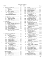
Table of Contents
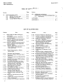
List of lllustrations
Model 608E/F
TABLE OF CONTENTS (Cont.)
Section
Page
Section
VI
6-1
6-1
6-1
6-1
6-1
vn
REPLACEABLE PARTS . . . . . • . . . .
6-1.
Introduction...............
6.3.
Replaceable Parts List. • . • • ••
6-6.
Ordering Information. • • • • • ••
6-9.
Factory Selected Parts (*). . . ..
Page
SCHEMATIC DIAGRAMS
COMPONENT LQCATION INFORMATION 7-1
7-1.
Introduction............... 7-1
APPENDIX 1. . . . . . . . . . . . . . . . . . . . . ..
1·1
APPENDIX IT. . • . . • • • . • • . • • • • • • . • . •.
IT-I
LIST OF ILLUSTRATIONS
Number
1-1.
3-3.
3-4.
4-1.
5-1.
5-2,
5-3.
5-4.
5-5.
5-6.
5-7.
5-8.
5·9.
5-10.
5-11.
5-12.
5-13.
5-14.
5-15.
5-16.
5-17.
Iv
Title
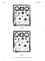
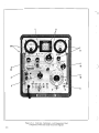
Model 608E and 608F'VHF Signal
Generators • . . . . . . . . . . . . . . . .
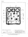
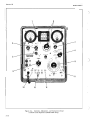
Front Panel Controls, Indicators,
and Cormectors• • . . • . . . . . . . . . .
Controls, Indicators and Connectors
Used in Operation with Internally
Generated Signals . . . . . . • . . • . • .
Controls, Indicators and Connectors
Used In Operation with Externally
Supplied Signals . . . . . . . . . . • . . .
Controls. Indicators, .:::.!:.1 ~::'''::''::::''=3
Used in Phase-Lock Operation
(Model 608F Only) . . . • . . . . . . . . .
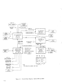
Overall Block Diagram, Models
608E and 608F
.
Fabricated Test EqUipment ...
Lubrication POints, RF 1\mer Drive
Mechanism. . . . • . . . . . . . . . . . . .
Frequency Accuracy and Resettability
Test Setup . . . • . . . . . . . . . . . . . .
Residual and inCidental FM Test Setup.
RF OutpJ.t Test Setup. . . . . • . . . . . •
Uncalibrated RF Output Test Setup ..
External Sine-Wave Modulation and
Modulation Meter Test Setup
.
Envelope Distortion Test Setup
.
Pulse Modulation Test Setup
.
RF Leakage Test Setup
.
Frequency Control Input TestSetup ..
Synchronization Test Setup
.
Location Power Supply and
Modulation Meter Adjustments . . . .
Modulation Meter Calibration Test
Setup. . . . . . . . . . . . • . . . . . . . . .
Pattern on 140 Oscilloscope at 50%
modulation
.
Location of Leveling and RF Output
Meter Adjustment
.
Location of RF Oscillator Adjustment
Page
1-0
3-2
3-6
3-8
3-10
4-0
5-3
5-4
5-5
5-6
5-7
5-8
5-"
5-10
5-10
5-11
5-11
5-12
5-13
Number
TtUe
Page
5-18. Frequency-Response Adjustments ...
5-18
5-19. Location of Frequency-Response and
Crystal-Calibrator Adjustments . . . . 5-18
5·20. Voltage and Resistance Measure
INT 1000 - Operation . . . • . . . . . . . 5-19
5-21. ALC Board Voltage and Resistance
Measurements, CW and PULSE
SET RF OUTPUT Operation
. 5-22
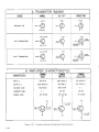
5_22. Transistor Biasing and Operating
Characteristics . . . • . . . . . . . . . . . 5-24
5·23. Location of Electron Tubes
. 5-28
5-24. Replacement of Oscillator and
Amplifier Tubes
. 5_29
5-25. Disassembly of Attenuator Drive
Cable. ,
. 5-30
5-26. Attenuator Probe, ShOWing Pickup
Loop and Impedance Matching Network 5-31
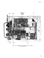
5_27. RF Generator Assembly Location of
Unlabeled Parts (Side Cover Removed) 5-32
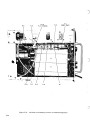
5-28. Model 608E RF Generator Assembly
ShoWing Location of Unlabeled Parts
(Top Cover Removed) . . . . . . . • . . • 5-33
5_29. Model 608F RF Generator Assembly
ShOWing Location of Unlabeled Parts
(Top Cover Removed).
. 5-34
5-30. Right Side View Showing Location of
Unlabeled Chassis Components . . . . . 5-35
5_31. Left Side View Showing Location of
Unlabeled Components
. 5-36
5-32. Rear View Showing Location of
Unlabeled Chassis Components
. 5-37
. 5-38
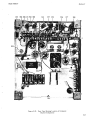
5·33. Circuit Board Parts Identification
5-14
7-1.
7-2.
7-3.
5-14
7-4.
5-15
5-16
7 -5.
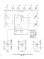
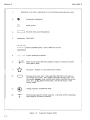
Schematic Wormation lllustration
_
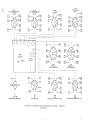
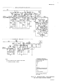
Schematic Diagram Notes
.
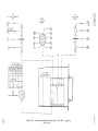
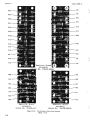
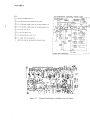
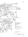
Component Identification, Modulator
and ALC Board
.
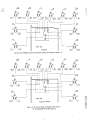
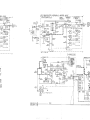
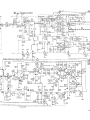
RF Generator and Modulator
Schematic Diagram
.
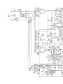
Modulation Meter, Crystal Calibration,
and Power Supply Schematic Diagram ..
)
,
7 -1
7-2
7-3
7-3
7 -5
)