1
Model 608 EI F
Section V
NOTE
Attenuator VSWR is determined by position·
ingofthe probe variable capacitor (C37) and
the relative position of the two resistors
(R58 and R59) on the end of the probe. If
replacement resistors are returned to their
original positions, the VSWR will not be
changed appreciably. However, if equipment is available for checking attenuator
VSWR, such a check is advisable following
replacement of resistors.
5-76. REMOVAL FROM HOUSING. If investigation
shows an attenuator to be defective, proceed as
follows:
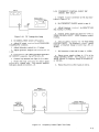
a. Turn attenuator control on front panel until probe
reaches end of its travel at rear of allenuator housing.
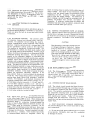
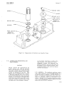
b. Remove nut and washers that hold drive cable
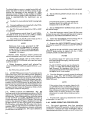
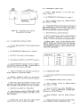
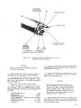
in probe drive screw (Figure 5-25) in top of attenuator probe.
c. Remove probe split drive screw from probe
body by removing inner nut and unscrewing.
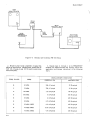
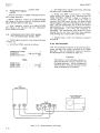
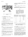
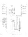
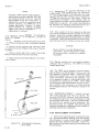
5-77. PROBE REPAIR. Capacitor C69 (Figure 5-26)
is held in place by a mounting straF and a setscrew.
To replace C69, unsolder the pickup loop at the capacitor end (ground slide of loop), loosen the setscrew,
and slide the capacitor out of the damp. Replace by
reversing this procedure. The capacitor must be
firmly seated in the hole in the end of the probe before
tightening the setscrew. Be careful when tightening
the setscrew; the capacitor ground lead can be cut in
two if the setscrew is tightened excessively.
5-78. Note location of the two resistors so that new
ones can be mounted as nearly as possible in the same
position. Install new resistors; duplicate the original
resistor mounting positions and lead lengths as closely
as possible. Make connections without excessive binding or pulling on ends of resistors as they are fragile.
CAUTION
These resistors are easily damaged by excessive heat. Use low-temperature soldering iron and solder connections as quickly
as possible.
d. Remove probe by carefuUy sliding it out of attenuator housing.
5-79. Measure resistors for any possible change tn
resistance due to soldering. The VSWR will not be
changed appreciably.
.J
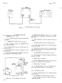
DRIVE CABLE
~
~
_
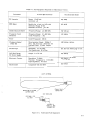
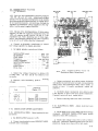
5-80. The VSWR can be checked at several frequencies on band E, and the position of rt<sistul'::, a:i" ...nd
R58 adjusted for optimum VS'NR. Adjustment on the
band E will automatically correct for minimum VSWR
on the lower bands. Laboratory test equipment, such
as an impedance bridge or reflectometer setup, will
be required for measuring the VSWR. These VSWR
checks must be made with attenuator inserted in attenuator housing in the instrument, as results obtained
will be slightly different with attenuator outside of the
housing.
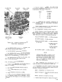
DRIVE SCREW
PR06E BOO1'
5-81. PROBE REPLACEMENT. II repair isnotpossible, both probe and cable must be replaced. Remove the RF OUTPUT connector from the front panel.
and release the cable from the clamp holding the cable
tothetopofthe side gusset. The entire probe assembly may then be removed from the instrument. Replacement probes are complete with cable and panel
connector; and require no adjustment oflhe impedancematching network upon installation.
5·82. REPLACEMENT IN HOUSING.
RF OUTPUT CABLE
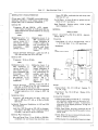
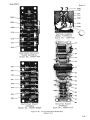
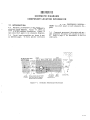
Figure 5-25.
5-30
Disassembly of Attenuator
Drive Cable
a. Insert new or repaired probe in atlenuator housing. Care must be taken in starting probe into housing,
since diameter at probe contact fingers is slightly
greater than inner diameter of hOUSing. Contact fingers should be depressed slightly while starting probe
into its housing.
•