1
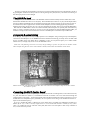
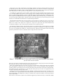
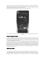
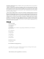
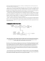
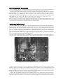
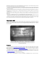
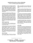
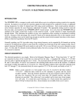
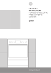
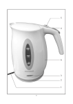
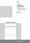
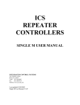
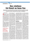
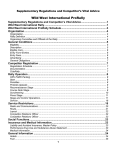
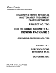
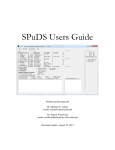
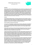
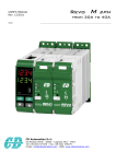
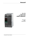
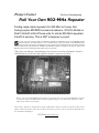
Project Corner
The Art of Homebrewing
Roll Your Own 902-MHz Repeater
Finding ready-made repeaters for 902 MHz isn't easy. But
finding surplus 800-MHz commercial radios is. W7UVH shows us
how to convert some of these units for use as 902-MHz repeaters.
A word of warning: This is NOT a beginner's project.
S
everal years ago, a friend of mine, Jon Marcinko, W7FHZ (now WR7JM), gave me an 800-MHz General
Electric (GE) Exec II Control Station to see if it could be used in any way in the 902- to 928-MHz ham band.
After converting the exciter and retuning the receiver (which can be retuned anywhere in the 902 to 928 band
without modification), I decided that the 45-MHz IF (intermediate frequency) oscillator in the receiver made it a bit
difficult to pursue any worthwhile plan (I'll explain why as we proceed).
"The project sat and only casual thoughts of its existence crossed my mind until I retired in
1986 and had to get all of my junk together and move it from my work area."
Photo A. Top view of an 800-MHz GE Exec II with receiver preamp. The receiver needs no modification to tune the
33-centimeter (902- to 928-MHz) amateur band, but significant changes are needed to make it function as a 902MHz repeater. (Photos by the author)
*Gene Colson, W7UVH, is retired from the mobile communications business. He has converted more than a dozen
surplus commercial repeaters, and he put one of the first 6-meter repeaters on the air back in the mid-1950s. Gene
lives in McCleary, Washington.
W7UVH ([email protected] )
The project sat and only casual thoughts of its existence crossed my mind until I retired in 1986 and had to get all of
my junk together and move it from my work area. Moving this big heavy unit (Photo A), I decided it was time to give
this shelved project more serious thought.
The 800-MHz band
To begin with, let's look at the scheme of the 800-MHz commercial band. Virtually all of the mobile units on this
band transmit 45 MHz below their receive frequency. With a 45-MHz IF, this offset is very easy for half-duplex radios,
since the oscillator and multipliers for the transmitter become the first injection frequency for the receiver's first IF. In
the transmit mode, audio is applied to the oscillator and the multipliers, with the resulting signal being switched to
amplifiers which bring output power up to 15 to 35 watts, depending on the radio. This is true in most 800-MHz radios.
But while this 45-MHz offset is fine for the commercial band (whose band plan was probably built around this easy
offset), it creates a problem for ham use. If you were to set up the transmitter for 902.250 MHz and add 45 MHz, you
would be receiving on 947.250-out of band! You can't have a 45-MHz split in a band that's only 26 MHz wide!
A Separate Receiver String
Well, I thought, that might be solved by having a separate receiver multiplier string. Looking closely at the multipliers,
I saw that the last multiplier is in the 400MHz band and is doubled to 800. Having previously used a GE MVP UHF
(450 to 512 MHz) exciter strip (Photo B) for a multiplier to arrive at an injection frequency for a GOES weather
satellite receiver, I thought, why not use one for the 900 MHz receiver?
Please note: The following conversion is necessary only for making a repeater out of the Exec II. Another scheme
will be used for using the Exec II as a control station or mobile, and it will be described later in this article.
Photo B. Exciter side of the GE MVP mobile radio. This exciter board can be modified to help turn an Exec II into a
33-centimeter repeater.
Converting the MVP Exciter Board
First question: where to put it? Simple enough. Lilt up the unit from the case and right there, in the bottom of the unit,
is a place lust made for it (Photo C). I mounted the board with six number 6-32 screws with washers through the
ventilation holes in the bottom ... but I'm getting ahead of myself. Before mounting the board, it's best tune it to receive
45 MHz above the multiplied frequency (remember, this is a separate receiver string, so the 45-MHz IF will have no
impact on the transmit frequency).
If we use a standard GE MVP or UHF Exec II exciter board (450 to 512 MHz), the modifications needed are as
follows (By the way, it will be extremely helpful to have a service manual and schematics available for any of these
radios -ed..). Reduce the size of L 108 and L 109 by half, then remove L113 and replace it with a loop of number 16
wire, 1/2 inch above the pc board.
(These are not very critical, because there are two helical resonators in the Exec II that will tune the circuit and
provide ample injection.) Next, some coils will require added capacitors, all of which are available in a single package
front Radio Shack, part number 272-806. I simply added these caps on the bottom of the pc board. Here's what goes
where: add 6 pF across T 105, 12 pF across T 106, 4 pF across T 107, and 3 pF across T 108.
To calculate the crystal frequency for the oscillator, simply subtract 45 from the desired receive frequency. In my
case, I use 902.250 MHz as the repeater's receive frequency, with a 25-MHz split that keeps both signals in the ham
band (see "Band Planning Problems" for more on 902-MHz repeater frequencies and offsets). Subtracting 45 from
902.25 equals 857.25 MHz. Remember that the frequency was doubled in the last multiplier stage, so divide 857.25 by
two and you get 428.625 MHz. Finally, using GE's formula, divide that number by 36, and you end up with a crystal
frequency of 11.90625 MHz. See "Resources" for crystal ordering information.
Now back to the exciter board. This conversion will be necessary in all Exec Its, whether the exciter is to be used as a
control station, a repeater, or a mobile. The following capacitors will need to be removed and replaced with the values
listed: C 127 = 22 pF; C 129 = 22 pF; C136 = 18 pF; C137 = 15 pF; C147 = 4 pF; C148 = 2 pF. On the oscillator board,
C22 should be changed to 18 pF. No other capacitors should be need or replaced, anywhere.
Now find the two helical resonators, Z101 and Z102. These are covered with copper and are wound on a very fragile
plastic. The tuning of these two stages is done by the dielectric of the plastic. Everything is very fragile. Remove these
two covers very carefully, then carefully cut 1/4 turn from each coil. Keep the wire in against the form as the tuning
portion may screw down over the coil. You don't want it to drag on the coil. On the radios
Photo C. An 800-MHz Exec II with an MVP UHF exciter board installed in the bottom
for use in the receiver section.
that I have converted, I've found that removing 1/4 turn gives the resonator a tuning range from 902 with the adjustment nearly all of the way in, and to 928 with it nearly all of the way out.
When you've finished and put the covers back on, I suggest you solder only a couple of spots until you've tuned the
unit as you might have to remove the covers a second time. In one case, I cut a 1/2 turn and had to take it apart again. I
was able to solder a 1/8-inch piece of wire across the coil from the end and it worked--I also broke one beyond repair.
From GE/Ericsson parts (see "Resources"), it was nearly $20. These parts may be on their "not supported" list, but it
can't hurt to check if they still have some in stock.
Tuning for this circuit or, for that matter, the receiver multiplier, should be done using the specific procedures set out
in the manual. I use a spectrum monitor when tuning such items. If you don't have access to one, you can also use a
receiver. By looking at the multiplication scheme, you should be able to figure the frequency of each stage and know
where to look or listen..
If the exciter is to be used for a repeater, then I would also suggest that you remove the relay, K1, and install a jumper
between pin 4, where the relay was, and ground. Also, jumper a wire between pins 1 and 3. This will put the RF out on
the receiver jack, but will keep active the "A" reading on the test set. With 10 volts permanently applied to both pins 1
and 8, you can use a pull-to-ground on pin 2 (F1) to key the transmitter.
Some additional notes: Feed the audio in on the mic line and not the on Channel Guard (CTCSS) line. The Channel
Guard line doesn't have deviation limiting and is not designed for the higher frequencies.
Photo D. A GE Mastr II 800-MHz repeater. This can also he modified to work on 902 MHz, but takes a different set of mods than
The Exec II.
Band Planning Problems
The 902- to 928-MHz band is one on which amateurs have a secondary allocation and a growing number of both
licensed and unlicensed (but legal) neighbors. Hams must avoid interfering with industrial, scientific, and medical
(ISM) devices, automatic vehicle monitoring (AVM) systems, and certain government stations. On the unlicensed side,
our most numerous neighbors are cordless phones.
What's the amateur band plan here? Well, as far as repeaters go, there really isn't one at the moment. For several
years now, the ARRL has been in the process of updating its original band plan (with 12-MHz repeater offsets) because
that plan's repeater subbands now pose potential conflicts with the AVM allocations at 904 to 921 and 918 to 926 MHz.
With the numerous (mostly non-amateur) current users of this band, I personally fail to see how a good band plan can
be adopted. At the time I selected 902.250 and 927.250 for my repeater, both frequencies were outside the AVM part of
the band and I didn't see many cordless phones in this area. Now that's changed and it seems that the entire band is
open to all kinds of services. As mentioned in the main article, I'm now hearing modulation from a cordless phone
somewhere near these frequencies.
Split Over Splits
A 25-MHz split seemed good when I first set up my repeater, as 800 MHz duplexers could be retuned to that split
with the least degradation, and I wanted to keep the mobile receive at the upper end of the band, as far away as
possible from cellular phones. Again, it now doesn't seem to make much difference. They have us surrounded. Some
thought might be given to 21.4-MHz offset, or even other splits, such as 9.4, 10.7, or 11.2 MHz (or the ARRL's
recommended 12 MHz). Experimenting with different offsets may help determine what's the best and easiest to
achieve-for a national standard.
Despite the negatives on 902 to 928, don't get discouraged. The band is ours (subject to sharing limitations) and we
should use it, even though we will suffer some problems from time to tine with other legal services. The surplus
commercial equipment is out there. Having worked in the 800-MHz services for a number of years, what I've learned
here has helped me a great deal. You'll have to learn some truths for yourself, about antennas, for instance, and about
not relying on vendors to tell you what they think their specs are. This is a band that's wide open to the experimenter
and it awaits exploring and exploiting.
Editor's Note: The ARRL hand plan sets aside 902 to 903 MHz for weak-signal operating, with 902.100
MHz as the SSB/CW calling frequency. In some parts of the country, weak-signal operation is centered on
903 MHz, with a calling frequency at 903.100. Gene's repeater transmit frequency of 902.250 seems to be far
enough away from both calling frequencies not to pose any interference problems, but anyone setting up a
repeater or other FM operation on this or any band should do everything possible to avoid interference to the
weak-signal areas. In addition (and this applies to all bands), you should check with the frequency
coordination group for your area to find out the local band plan, including repeater offsets, frequency
availability, etc.. These groups are listed in the ARRL Repeater Directory. Our publication of this article does
not constitute an endorsement of the author's frequency choices. Please note also that amateur operation
within the 904- to 921- and 918- to 926-MHz AVM windows is permitted as long as there is no interference
to AVM systems. So if there is no AVM activity in your area, or you can avoid active AVM frequencies, you
may operate within those band segments.
Parts List
MVP Exciter Board
Repeater-only Modification
(1) 3-pf capacitor
(1) 6-pf capacitor
(1) 4-pf capacitor
(1) 12-pf capacitor (all are available in a single package from Radio Shack, part #272-806) Short
length of #16 wire
All-uses Modification
Crystal (see text)
(1) 15-pf capacitor
(1) 2-pf capacitor
(1) 18-pf capacitor
(1) 4-pf capacitor
(2) 22-pf capacitor
MVP Oscillator Board
(1) 18-pf capacitor
Exec II Modification (changing IF Freq.)
(1) 34.4-MHz oscillator crystal (for 25-MHz IF and offset; frequency will change if other IF/split is
chosen; see text) (1) 4-pf capacitor (3) 33-pf capacitor
MVP Transmitter (when using MVP intact as transceiver)
(1) Crystal (1/48 of chosen transmit frequency; see text) (1)10-pf capacitor (2)12-pf capacitor (1) 15pf capacitor (1) 22-pf capacitor (1) 33-pf capacitor
Mastr II
Exciter
(1) Crystal (1/48 of chosen transmit frequency; see text) (1) 15-pf capacitor (1) 22-pf capacitor (1) 27pf capacitor (1) 39-pf capacitor
Receiver
(l) Crystal (1/48 of chosen transmit frequency; see text)
Mitrex "Maybe Amplifier"
(2) .001-µF feed-thru capacitor Teflon® coax (see text)
(1) Muffin fan
(1) 3-inch piece of 1/2–inch aluminum tubing
The output of the exciter will be around 50 to 65 milliwatts and
will drive the PA (power amplifier) to its rated power of 25 or 35
watts (depending on the specific radio you start with). My current
repeater is running 35 watts output. Finally, the high-pass filter is
not a problem, but you might gain a watt or two by carefully
spreading the coils a little or adjusting them in different ways.
This completes the conversion of the Exec II for use as a
repeater or as a control station with the 45-MHz IF left intact and
a separate oscillator/multiplier strip. For more on converting the
Exec II to a repeater, there's an excellent Web site (see
“Resources") from which you can download all the information
you’ll need.
A Different Approach
Now let's look at an alternative way of keeping the one-oscillator/multiplier method used in most 800-MHz
radios. Note that you cannot use this method for full-duplex operation (simultaneous transmitting and
receiving), so it will not work for repeaters. What we're going to do here is change the IF from 45 MHz to 25
MHz, maintaining the original circuit design of the radio, but keeping both receive and transmit frequencies
within the ham band.
Let's start by examining the radio before modification. The transmit oscillator in these radios runs all the
time, but is without modulation in the receive mode, thus generating a receiver IF of 45 MHz. From the
schematic in your manual (you do have the manual, right?) you'll see that there's an amplifier tuned on the input
and the output directly following the first mixer, followed by a 45-MHz 4pole filter. This filter provides more
than 30 dB of adjacent channel rejection.
Next we move from the filter and another tuned circuit to the second mixer. Here, A 35.6-MHz crystal
oscillator plus the second IF (9.4 MHz) equals the 45MHz first IF. Now, if we were to change the second
oscillator frequency to 34.4 MHz, then subtract the second IF (9.4 MHz), we'd end up with 25 MHz, which, as
noted above, is the split I've chosen for my repeater and which I felt at the time was a good offset for 902 to
928 MHz (again, see "Band Planning Problems" for more on offsets, etc.). If we remove the crystal filter and
pad the coils down to 25 MHz, it will work (see Figure for block diagram of this arrangement).
A side-note here: There's nothing magical about a 25-MHz split except that it works, and I've converted
several radios using that offset and don't want to start over. For those who are starting from scratch, though,
there are other possibilities. For example, there are a lot of 21.4MHz crystal filters around and, if you wanted to
keep better selectivity in a metropolitan area, you might give some thought to a 21.4-MHz offset. The second
oscillator would be 30.8 MHz and more "c" would have to be added to all of the coils. I haven't tried this
scheme, but it might be a thought. Now, back to the 25-MHz plan.
In this conversion, the receiver has not suffered in sensitivity but has given up quite a bit in adjacent channel
rejection. I can live with that, although I must admit that with a very good preamp, and without Channel
Guard, I do hear some modulation from someone using a 900-MHz cordless phone. I've noticed that most
analog phones deviate 15 kHz or more. CTCSS is desirable anyway. By the way, many cordless phones are also
using a 25-MHz offset.
Changing the Offset to 25 MHz
927.250
25 MHz
902.250
Driver
PA
Figure. Block diagram of a single oscillator/multiplier string applied to both receive and transmit. Note that the 927.250MHz received signal mixes with the 25-MHz IF to arrive at the local oscillator (and not coincidentally, transmit) frequency of
902.250 MHz. Using the radio's original 45-MHz IF would result in an out-of-band receive frequency. The local
oscillator/multiplier chain is switched between receive and transmit.
Here's how to make your Exec II or the MVP receiver operate with a 25-MHz offset--no adjustments are required
in this circuit, just a new crystal and some added capacitors. First, replace Y1, the 35.6-MHz second oscillator crystal,
with a 34.4-MHz crystal. This crystal might be available from any of the crystal manufactures, but International has the
GE part number (19B206221G3) in its inventory and will cut it to 34.4 MHz (International's catalog number is
471460). Next, remove the crystal filter, FL1, and, jumper a 4-pF capacitor from the input of where the crystal filter
was to the output side. Add a 33-pF cap from the input side to ground, and another 33-pF cap from the output side to
ground. This adds 33 pF to L2 and L4. Then add yet another 33-pF cap across L1 terminal 6 to ground. That will put
everything very close to 25 MHz.
If you first tune up the receiver to somewhere in the 902- to 928-band, it will be very easy to tune the 25-MHz stages,
as they are rather broad. Perhaps this scheme will turn on a few lights and some of you who are more knowledgeable
about synthesized radios might come up with some ideas for those units. My experience though is that many of the
newer radios went to fixed front-end filters and cut off very abruptly above 890 MHz.
MVP Transmitter Conversion
These conversions so far have covered the Exec II transceiver and the MVP receiver. Now to the MVP transmitter, in
case you're using the MVP intact as a control unit or mobile rig, rather than pulling out the exciter board.
The MVP uses the same oscillator frequency as the Exec II, and the 2C ICOM oscillator modules are interchangeable
(see "The Other ICOM" for more on these precision crystal oscillators), but the multipliers are a little bit different.
Essentially, though, you're multiplying by 48, so you'd need a crystal frequency of 18.796875 MHz to produce a
transmit frequency of 902.250 MHz (see Figure). The following capacitors need to be removed and replaced with the
following values: C 113 = 33 pF; C 114 = 22 pF; C 123 = 12 pF; C 125 = 10 pF; C 133 = 15 pF; C 135 = 12 pF.
The helical resonators, Z 101 and Z 102, are the same as in the Exec II. Carefully
Remove the copper covers and cut 1/4 turn off each. Re-install and tune. At 10 watts out, this little MVP makes a very
nice control station, even though it is kind of large for a front-mount mobile in most vehicles today. I have a small
control head that I've made and, one of these days, I'll have a trunk mount MVP.
Converting the Mastr II
The Mastr II station or repeater (Photo D) is again a bit different front the Exec II or MVP. The transmitter and
receiver are totally independent of each other, in that they each have their own oscillators. The exciter and the receive
oscillator (Photo E) each use a 1C ICOM for frequency control. The 1C is a 1 part per million oscillator only and does
not have a modulator. It's used here because the Mastr 1I is a phase-modulated FM radio. Conversion is about the same
as the Exec II or MVP, although-again-the multiplication is a little different. In the end, though, you're still multiplying
by 48. The same procedures apply to the two output resonators, Z101 and Z102. Remove 1/4 turn from each. And the
capacitors to change are as follows: C 127 = 27 pF; C 129 = 22 pF; C 136 = 39 pF; C 137 = 39 pF; C 147 = 15 pF: C
148 = 15 pF. Tuning of this exciter is easy and straightforward.
The receiver side's oscillator/multiplier is a bit different, even though the multiplication is still 48 times, and conversion is very simple. Change C404 to 33 pF and C410 to 10 pF. The two copper resonator covers and Z 401/Z 402 are of
Photo E. Close-up view of the Mastr II receiver and exciter drawer.
the same construction as the other ones, except that these are at 400 MHz, not 800. The coils are made of enamelcoated wire. In this case, carefully remove one full turn From each coil. There is no 800- or 900- MHz tuning on this
board. The helical resonators, L306 and L307, tuned by C306 and C307, will tune the output of the multiplier board for
the injection 45 MHz below the receive frequency (again, with independent transmit/ receive oscillators, there's no need
to change the IF frequency in order to operate at a split other than 45 MHz).
That's all there is to the Mastr II conversion. The 35-watt PA will deliver 25 to 35 watts. This will vary from unit-tounit, and some massaging of the output filter may increase output. If you intend to use this amp to drive a non-GE
amplifier you may have more than you need anyway. The original GE high-power amp required the full 35 watts to
obtain full power. A couple of amplifiers that I've put together, which are described below, require only 5 to 8 watts to
get 80 to 90 watts output, so even the 10-watt MVP does very well.
The Other ICOM
A few words about crystals and GE "ICOMs." These are not made by the ICOM
America with which we hams are familiar (although the company does make similar
precision crystal modules for some of its high-end radios). In this case, ICOM
is GE's abbreviation for "Integrated Crystal Oscillator Module," which is
generically known as a TCXO, or Temperature Compensated Crystal Oscillator.
Extreme heat or cold will change a crystal's frequency, so these precision
crystal oscillator modules include "temperature compensation" (heating or
cooling) to keep the crystals' frequencies within exact tolerances. The
temperature compensation feature kicks in at temperatures below 32 degrees F or
above 131 degrees F.
Each of these oscillator modules is slightly different and serves a specific
function. For example, the 1C ICOM used in the Mastr II is a high-stability
oscillator only and cannot be used in the Exec II or MVP because it does not
include a modulator. Those radios use a 2C ICOM, which has its own FM modulator
built in and cannot be used in the phase-modulated Mastr II. Finally, the EC
ICOM requires external temperature compensation. No compensation is available on
any of these three units, so the ECs are out as far as they're concerned.
As for sending ICOMs in to Ericsson for new frequencies, I've had very good
results in buying the crystals and installing them myself. I've stayed with two
of the major, long-time vendors (see "Resources"), monitor my repeater
frequencies very closely, and have had no problems. Some people may not be
comfortable working on these precision modules and may feel the expense of
having the frequency changed professionally is worthwhile. You have to do what
you feel is right for you.
A "Mitrex Maybe" Amp
At one of the ham fairs last year, a stack of 800-MHz Motorola Mitrex mobiles sat until the show was nearly over,
the price
dropping by the minute, until a friend of mine, Fred Baker, W7SIX, came over and dumped four of them on my table. I
guess he came up with a real bargain.
What to do with 800-MHz mobiles? No manuals, no information, nothing! Months later, I took one apart. The first
thing I found was that the bandpass filters would not do 900 MHz, so it looked pretty bleak. I never cared much for the
type of PAs used in the UHF radios, and these did not look any better. Maybe the transistors were good for something.
I searched the Internet and all available cross-reference books and came up with a zero all the way around.
The rest of the radio wasn't much good for 900 MHz either, so with nothing to lose, I decided to see if some of the
parts could be useful. Maybe I could build an amplifier for 902. I removed the PAs from two of the units and a driver
from one of them. I took out all of the white Teflon© coax, too. Then, from among my "someday projects," I dug out a
GE Mastr II heatsink. I drilled and tapped 4/40 screw holes to mount two of the "35-wattlooking" PAs side by side,
nearly in the middle of the heatsink. I attached a BNC connector and a short lead of 4 or 5 inches of coax to the driver
input, and I mounted the driver close enough to the PAs that I could use a quarter-wavelength of the white Teflon coax
to get to the amplifier inputs (Photo F).
The velocity factor of the coax was unknown, so I just took sort of a guess and decided maybe 2 1/4 inches would
be about right. I ran two lines in parallel from the output of the driver, one running to each PA input. The PA outputs
were too far apart for a 1/4-wave, so I made two 3/4-quarter wavelength sections, about 7 3/4 inches each. I ran these
from the output of each PA to an N connector where they both were tied together.
Next, I supplied 12 volts DC to each amplifier with a separate lead, using a ferrite bead on each amplifier close to the
board. Each power lead went through a .001 -pF feed-thru capacitor before being joined to one large power lead.
Testing the "Maybe" Amp
I set up a converted MVP on 900 MHz with tile power control turned all the way down. I must confess that I was
absolutely amazed when power was applied and I started to increase the power on the MVP-things really started to
happen on the output of the new amplifier. At 7 watts input, I had over 50 watts output.
Experimenting with may different ideas, I came up with the following to achieve roughly 90 watts of continuous
power out: Add a 2 1/4-inch piece of the Teflon coax, shorted on one end, to the point on the driver board where the
two cables go to the PAs. All of these should have a common ground point next to the center conductor. I used a short
length of heat shrink over the shorted end of the stub, made another one and connected it, in the same fashion, to the
point where the PAs and the antenna came together. At this point, a lot of heat is generated in the coax. 1 put heat
shrink tubing over these four pieces of coax and slid them into a 3-inch length of 1/2-inch aluminum tubing, then made
up a bracket to hold the tube a couple of inches up from the heatsink.
I've made two of these amplifiers and both turned out about the same. One has 95 watts out, while I could only get 85
out of the other. If I had more of these, I'd like to try a true Wilkerson divider for the PAs. Maybe someone has tried
that or will in the future.
By the way, all of the time these were being tested, I was using a spectrum monitor and watching it very closely. I
saw nothing out of the ordinary from DC to 1 GHz. Running the output power through a bandpass cavity showed only
the cavity loss.
Finally, I mounted a small Muffin fan on the amplifier. With this configuration, I've had the PA keyed at its full 90
watts for many hours with no change in power or heating. On the other hand, the 100-watt dummy load had to have a
big fan on it!
And, oh yes ... along the way, I broke one of those wonderful white ceramic type-a boards. I soldered the runs with
an extra amount of solder and, believe it or not, it worked just fine (it's a part of the 90-watt unit).
The Mitrex also has a pre-driver, and I tried using one of these in front of the driver. All that happened was that I had
to reduce drive to less than 2 watts and there was some slight instability in the pre driver. With 6 to 8 watts of input
power available from the MVP, I set that aside and stuck with the driver/dual amplifier configuration.
Got a Better Idea?
Someone might come up with a better PA from these little units, and I hope they do. I still don't know what the
transistors are or what they're rated at, nor do I have any idea what the impedances should be at some of the points in
the circuit. I guess it doesn't matter too much. I now have two high-power amps that I didn't have before ... and four
fewer boat anchors.
Photo F. The "Mitrex Maybe" amplifier. Built from two power amplifiers and a driver from
surplus Motorola Mitrex transceivers, and mounted on a GE Mastr II heatsink, the unit amazed
the author by working the firs! tittle and producing 95 watts out for about 8 in. This is one of
two amps he's built this way.
Resources
For more information on converting GE Exec II radios to amateur repeaters, Ron Wright, N9EE, has an excellent
guide on the Internet at <http://www.cdi2. com/build_it/ex2reptr.htm>. This is one of many postings on the "Amateur
Repeater Builder's Home Page" put together by Eric Homa, N6NMZ. If you're interested in the challenge of building a
repeater, check out this excellent resource at <http://www.cdi2.com/build_it/>.
GE radios are now made and supported by Ericsson. Parts may be ordered by contacting Ericsson, Attn.: Service
Parts, Mountain View Rd., Lynchburg, VA, 24502; Phone: (800) 368-3277. Additional information is available online
at <http://www.ericsson.com> or <http://www.ericsson.se>.
I order my crystals from either of the following two companies:
Bomar Crystal Co., 201 Blackford Ave., P.O. Box 10, Middlesex, NJ 088460010; Phone: (732) 356-7787; Fax:
(732) 356-7362; E-mail: <[email protected]>; Web: <http://www.bomarcrystal.com>.
International Crystals, P.O. Box 26330, Oklahoma City, OK 73126; Phone: (800) 725-1426 (orders only) or (405)
236-3741; Fax: (405) 235-1904 or (800) 322-9426; E-mail: <[email protected]>; Web: <hlttp://www.icmfg.com>.
Footnote: (kb8gvq) “ GE ET/AL” is now owned By Ma/Com Inc. a Tyco Electronics affiliate company…
UP DATED MATERIAL
The values of the caps listed in the conversion of the MVP were values used at the high end of
the band. If the conversion is for the 902 area, try tuning as is first. Some units may only require the
change in C113, C114. Since the frequency is right on the edge of its 800 mhz range, they will very
some. If the plastic dielectric tunning cups in the Z 101 and Z 102 get broken and can not be fixed, I
have soldered a brass washer and an 8-32 nut over the hole, used an 8-32 screw to tune the stage.
Some experimenting may be required.
A word of caution about omni antennas used on 902-928 MHz. One antenna that was tried and with
60 watts of RF, burned up, was an antenna made by CushCraft for 902-928. The antenna is a printed
circuit antenna with some sponge material to hold things in place. I suspect the material got soaked up
with water. Avoid ! !
I have converted several commercial 800 MHz. Antennas with fair results. If try this, don't take more
than a quarter of an inch off of anything. The best antenna so far is a Collinear design by WA6SVT,
modified for 902-928 MHz. Data can be viewed at http://www.kuggie.com/rbtip/wa6svt.html .
Values and dimensions are critical. Save yours self allot of time and work, if you intend to build one,
I will give you the details.
Gene
Sept 2000
Re-Type set and scanned/converted by Douglas Bade KB8GVQ with
the permission of Gene Colson W7UVH.
As this was a scanned edit, some errors may be present, if any are
found, please advise me at [email protected] and I will correct
them..
Thanks, Doug KB8GVQ