1
ÎÎ
GE Fanuc Automation
Programmable Control Products
MMS-Ether net Communications for the
Series 90 -70 PLC
User’s Manual
GFK-0868
May 1994
GFL–002
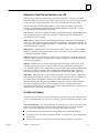
Warnings, Cautions, and Notes
as Used in this Publication
Warning
Warning notices are used in this publication to emphasize that hazardous voltages,
currents, temperatures, or other conditions that could cause personal injury exist in this
equipment or may be associated with its use.
In situations where inattention could cause either personal injury or damage to
equipment, a Warning notice is used.
Caution
Caution notices are used where equipment might be damaged if care is not taken.
Note
Notes merely call attention to information that is especially significant to understanding
and operating the equipment.
This document is based on information available at the time of its publication. While
efforts have been made to be accurate, the information contained herein does not
purport to cover all details or variations in hardware or software, nor to provide for
every possible contingency in connection with installation, operation, or maintenance.
Features may be described herein which are not present in all hardware and software
systems. GE Fanuc Automation assumes no obligation of notice to holders of this
document with respect to changes subsequently made.
GE Fanuc Automation makes no representation or warranty, expressed, implied, or
statutory with respect to, and assumes no responsibility for the accuracy, completeness,
sufficiency, or usefulness of the information contained herein. No warranties of
merchantability or fitness for purpose shall apply.
The following are trademarks of GE Fanuc Automation North America, Inc.
Alarm Master
CIMPLICITY
CIMPLICITY 90–ADS
CIMPLICITY PowerTRAC
CIMSTAR
GEnet
Genius
Genius PowerTRAC
Helpmate
Logicmaster
Modelmaster
ProLoop
PROMACRO
Series One
Series Three
Series Five
Copyright 1992 GE Fanuc Automation North America, Inc.
All Rights Reserved
Series Six
Series 90
VuMaster
Workmaster
Preface
Content of This Manual
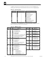
Chapter 1.
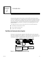
Introduction: Discusses the Ethernet Interface, the communications software, and the GEnet System Manager.
Chapter 2.
Installing the Ethernet Interface: Describes the basic features of the
Ethernet Interface, the installation and power–up of the Interface, and a
procedure for the initial checkout of the Interface on your Ethernet cable.
Chapter 3.
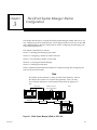
The GEnet System Manager–Station Configuration: Describes the installation and operation of the GEnet System Manager and how to configure a
Series 90–70 PLC Ethernet Station for a Basic Network.
Chapter 4.
The Station Manager: Describes how to use the Station Manager to provide interactive supervisory access to the Ethernet Interface.
Chapter 5.
General PLC Application Programming: Explains fundamental features of
the interface between the PLC application program and the LAN Interface.
Describes how to program the PLC to initiate COMMunication REQuests.
Chapter 6.
OSI COMMunication REQuest: Defines the OSI service commands and parameter descriptions, and explains how to program each communication request.
Chapter 7.
Station Manager COMMunication REQuest: Explains how to use the
COMM_REQ in the ladder logic application program to retrieve station
management information.
Chapter 8.
Tuning and Configuring Stations for an Advanced Network: Describes
the additional configuration parameters needed to configure and tune stations in an advanced network environment.
Chapter 9.
Troubleshooting: Describes troubleshooting and problem isolation for the
Ethernet Interface.
Appendix A. Glossary of Terms
Appendix B. ISO Networking Concepts
Appendix C. Protocol Implementation Conformance Statement (PICS)
Appendix D.Communications Port Characteristics
Appendix E. Soft Switch Parameters
Appendix F. Station Configuration Parameters
Appendix G.Ladder Diagrams for Network Testing
Appendix H.DOS System Initialization Files
Appendix I. Forms
Appendix J. GEnet System Manager Data Link Error Codes
iii
GFK–0868
Preface
Related Publications
t
GFK–0262
Series 90 – 70 Programmable Controller Installation and Operation
GFK–0263
Logicmaster 90
GFK–0265
GFK–0780
t Programming Software User’s Manual
Logicmaster 90t Programming Software Reference Manual
Logicmaster 90t –70 – Ethernet User’s Manual
At GE Fanuc Automation, we strive to produce quality technical documentation. After
you have used this manual, please take a few moments to complete and return the
Reader ’s Comment Card located on the next page.
We Welcome Your Comments and Suggestions
At GE Fanuc automation, we strive to produce quality technical documentation. After
you have used this manual, please take a few moments to complete and return the
Reader ’s Comment Card located on the next page.
iv
MMS-Ethernet Communications for the Series 90-70 PLC User’s Manual - May 1994
GFK–0868
Contents
Chapter 1
Chapter 2
Introduction . . . . . . . . . . . . . . . . . . . . . . . . . . . . . . . . . . . . . . . . . . . . . . .
1-1
The Ethernet Communications System . . . . . . . . . . . . . . . . . . . . . . . . . . . . . .
1-1
The Ethernet Interface . . . . . . . . . . . . . . . . . . . . . . . . . . . . . . . . . . . . . . . . . .
1-2
The GEnet System Manager (GSM) . . . . . . . . . . . . . . . . . . . . . . . . . . . . . . .
1-4
How to Make it Work . . . . . . . . . . . . . . . . . . . . . . . . . . . . . . . . . . . . . . . . . . . . .
1-5
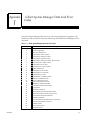
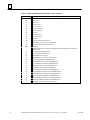
Quick Guide to the Manual . . . . . . . . . . . . . . . . . . . . . . . . . . . . . . . . . . . . . . . .
1-6
Installing the Ethernet Interface . . . . . . . . . . . . . . . . . . . . . . . . . . . . .
2-1
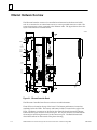
Ethernet Hardware Overview . . . . . . . . . . . . . . . . . . . . . . . . . . . . . . . . . . . . . .
2-2
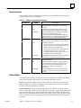
Board Indicators . . . . . . . . . . . . . . . . . . . . . . . . . . . . . . . . . . . . . . . . . . . . . . .
2-3
Restart Button . . . . . . . . . . . . . . . . . . . . . . . . . . . . . . . . . . . . . . . . . . . . . . . . .
2-3
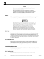
Battery . . . . . . . . . . . . . . . . . . . . . . . . . . . . . . . . . . . . . . . . . . . . . . . . . . . . . . .
2-4
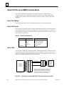
Serial Port . . . . . . . . . . . . . . . . . . . . . . . . . . . . . . . . . . . . . . . . . . . . . . . . . . . . .
2-4
AUI (Transceiver) Port . . . . . . . . . . . . . . . . . . . . . . . . . . . . . . . . . . . . . . . . . .
2-4
Default Station Address Label . . . . . . . . . . . . . . . . . . . . . . . . . . . . . . . . . . .
2-4
Serial Number Label . . . . . . . . . . . . . . . . . . . . . . . . . . . . . . . . . . . . . . . . . . .
2-4
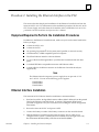
Procedure 1: Installing the Ethernet Interface in the PLC . . . . . . .
Equipment Required to Perform the Installation Procedures . . . . . . . . . . . .
2-5
Ethernet Interface Installation . . . . . . . . . . . . . . . . . . . . . . . . . . . . . . . . . . . . . .
2-5
Procedure 2: Verifying Proper Power-Up of the Interface . . . . . .
2-8
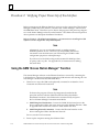
Using the GSM “Access Station Manager” Function . . . . . . . . . . . . . . . . . . . .
2-8
States of the Ethernet Interface . . . . . . . . . . . . . . . . . . . . . . . . . . . . . . . . . . . . .
2-9
Powering–Up the Interface . . . . . . . . . . . . . . . . . . . . . . . . . . . . . . . . . . . . . . . . .
2-10
Problems During Power–Up . . . . . . . . . . . . . . . . . . . . . . . . . . . . . . . . . . . . . . . .
2-11
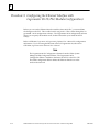
Procedure 3: Configuring the Ethernet Interface with
Logicmaster 90-70 (PLC Module Configuration) . . . . . . . . .
2-12
Procedure 4: Configuring and Downloading a Station . . . . . . . . .
2-13
Configuring a Station . . . . . . . . . . . . . . . . . . . . . . . . . . . . . . . . . . . . . . . . . . . . .
2-13
Downloading a Station . . . . . . . . . . . . . . . . . . . . . . . . . . . . . . . . . . . . . . . . . . . .
2-14
Initiating the Download . . . . . . . . . . . . . . . . . . . . . . . . . . . . . . . . . . . . . . . .
2-15
Problems During the Download . . . . . . . . . . . . . . . . . . . . . . . . . . . . . . . . .
2-16
How to Issue the LOAD Command from the Station Manager . . . . . . .
2-16
Procedure 5: Testing the Interfaces on the Network . . . . . . . . . . .
GFK–0868
2-5
2-17
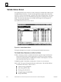
Field Network Test Utility . . . . . . . . . . . . . . . . . . . . . . . . . . . . . . . . . . . . . . . . . .
2-17
Invoking the Field Network Test Utility . . . . . . . . . . . . . . . . . . . . . . . . . . .
2-17
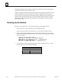
Running Field Network Test . . . . . . . . . . . . . . . . . . . . . . . . . . . . . . . . . . . . .
2-18
MMS–Ether net Communications for the Series 90–70 PLC User’s Manual – May
1994
v
Contents
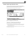
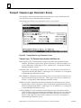
Procedure 6. Using the Example PLC Ladder Program . . . . . . . . .
Chapter 3
Loading the Example Station Configurations . . . . . . . . . . . . . . . . . . . . . . . . .
2-22
Loading the Example PLC Ladder Program . . . . . . . . . . . . . . . . . . . . . . . . . .
2-22
Executing the Example PLC Ladder Program . . . . . . . . . . . . . . . . . . . . . . . . .
2-23
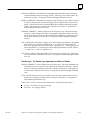
What to Do if the Program is Not Working . . . . . . . . . . . . . . . . . . . . . . . . . . .
2-25
Resuming Normal Operation After Using the Example Program . . . . . . . .
2-26
The GEnet System Manager-StationConfiguration . . . . . . . . . . . . .
3-1
What is the GSM? . . . . . . . . . . . . . . . . . . . . . . . . . . . . . . . . . . . . . . . . . . . . . . . . .
3-2
Why Does a Station Have to be Configured and Downloaded? . . . . . . . . . .
3-3
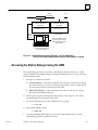
Connecting the GSM to the LAN Interface . . . . . . . . . . . . . . . . . . . . . . . . . . .
3-3
Section 1. Installing and Starting-Up the GSM . . . . . . . . . . . . . . .
GFK–0868
2-22
3-4
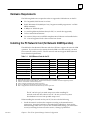
Hardware Requirements . . . . . . . . . . . . . . . . . . . . . . . . . . . . . . . . . . . . . . . . . .
3-5
Installing the PC Network Card (for Network GSM Operation) . . . . . . . . .
3-5
Installing the GEnet System Manager (GSM) Software . . . . . . . . . . . . . . . . .
3-6
Setting-Up DOS System Files . . . . . . . . . . . . . . . . . . . . . . . . . . . . . . . . . . . . . . .
3-8
Local GSM Operation (Exclusively) . . . . . . . . . . . . . . . . . . . . . . . . . . . . . . .
3-8
Network GSM Operation (or Both Local and Network) . . . . . . . . . . . . .
3-8
Unusual Procedures . . . . . . . . . . . . . . . . . . . . . . . . . . . . . . . . . . . . . . . . . . . . . . .
3-12
Updating or Adding to Existing GSM Software . . . . . . . . . . . . . . . . . . . . .
3-12
Changing the PC Network Card . . . . . . . . . . . . . . . . . . . . . . . . . . . . . . . . .
3-12
Starting-Up the GSM . . . . . . . . . . . . . . . . . . . . . . . . . . . . . . . . . . . . . . . . . . . . . .
3-13
Working Your Way through the GSM Menus . . . . . . . . . . . . . . . . . . . . . .
3-14
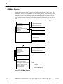
GSM Keyboard Functions . . . . . . . . . . . . . . . . . . . . . . . . . . . . . . . . . . . . . . .
3-15
GSM Menu Structure . . . . . . . . . . . . . . . . . . . . . . . . . . . . . . . . . . . . . . . . . . .
3-16
MMS–Ether net Communications for the Series 90–70 PLC User’s Manual – May
1994
vi
Contents
Section 2. Configuring a Station for a Basic Network . . . . . . . . . .
Definition of a Basic Network . . . . . . . . . . . . . . . . . . . . . . . . . . . . . . . . . . . . . .
Information Needed to Configure an Ethernet Station for a Basic Network
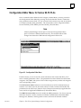
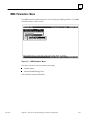
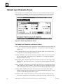
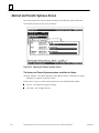
Configure a Station Screen . . . . . . . . . . . . . . . . . . . . . . . . . . . . . . . . . . . . . . . . .
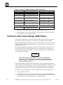
Creating a Station Configuration File . . . . . . . . . . . . . . . . . . . . . . . . . . . . .
Selecting a Station Configuration File . . . . . . . . . . . . . . . . . . . . . . . . . . . . .
Deleting a Station Configuration File . . . . . . . . . . . . . . . . . . . . . . . . . . . . .
Structure of the MAC Address . . . . . . . . . . . . . . . . . . . . . . . . . . . . . . . . . . .
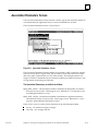
Configuration Editor Menu for Series 90-70 PLCs . . . . . . . . . . . . . . . . . . . . .
Saving Changes Before Exiting the Configuration Editor Main Menu . .
ISO Parameters Menu . . . . . . . . . . . . . . . . . . . . . . . . . . . . . . . . . . . . . . . . . . . . .
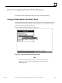
Network Layer Parameters Screen . . . . . . . . . . . . . . . . . . . . . . . . . . . . . . . . . .
Transport / Session Layer Parameters Screen . . . . . . . . . . . . . . . . . . . . . . . . . .
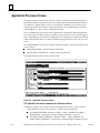
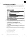
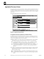
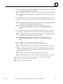
Application Processes Screen . . . . . . . . . . . . . . . . . . . . . . . . . . . . . . . . . . . . . . .
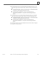
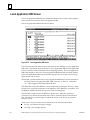
Local Application DIB Screen . . . . . . . . . . . . . . . . . . . . . . . . . . . . . . . . . . . . . . .
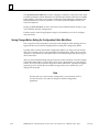
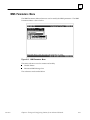
MMS Parameters Menu . . . . . . . . . . . . . . . . . . . . . . . . . . . . . . . . . . . . . . . . . . .
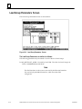
Variable Names Screen . . . . . . . . . . . . . . . . . . . . . . . . . . . . . . . . . . . . . . . . . . . .
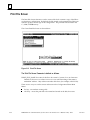
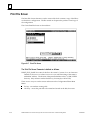
Print File Screen . . . . . . . . . . . . . . . . . . . . . . . . . . . . . . . . . . . . . . . . . . . . . . . . . .
Configuring a Non-GE Fanuc Device . . . . . . . . . . . . . . . . . . . . . . . . . . . . . . . .
Foreign Device Configuration Editor Menu . . . . . . . . . . . . . . . . . . . . . . . . . . .
Foreign Application Processes Screen . . . . . . . . . . . . . . . . . . . . . . . . . . . . . . . .
Section 3. Downloading a Station . . . . . . . . . . . . . . . . . . . . . . . . . . .
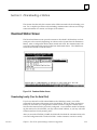
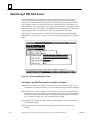
Download Station Screen . . . . . . . . . . . . . . . . . . . . . . . . . . . . . . . . . . . . . . . . . .
Downloading Locally (Over the Serial Port) . . . . . . . . . . . . . . . . . . . . . . . .
Downloading Over the Network . . . . . . . . . . . . . . . . . . . . . . . . . . . . . . . . .
Section 4. Accessing the Station Manager . . . . . . . . . . . . . . . . . . . .
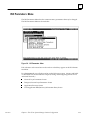
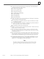
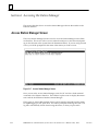
Access Station Manager Screen . . . . . . . . . . . . . . . . . . . . . . . . . . . . . . . . . . . . .
Section 5. Using the GSM Support Functions . . . . . . . . . . . . . . . .
Chapter 4
3-17
3-17
3-19
3-20
3-21
3-21
3-21
3-23
3-24
3-25
3-26
3-27
3-28
3-30
3-31
3-32
3-34
3-35
3-35
3-37
3-39
3-39
3-39
3-40
3-42
3-42
3-43
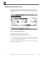
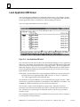
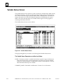
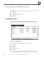
List All Stations Screen . . . . . . . . . . . . . . . . . . . . . . . . . . . . . . . . . . . . . . . . . . . .
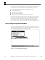
List All Configured Application DIBs Menu . . . . . . . . . . . . . . . . . . . . . . . . . . .
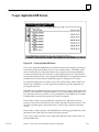
7-Layer Application DIB Screen . . . . . . . . . . . . . . . . . . . . . . . . . . . . . . . . . . . . .
Setup GSM Menu . . . . . . . . . . . . . . . . . . . . . . . . . . . . . . . . . . . . . . . . . . . . . . . . .
Changing the GSM Password Screen . . . . . . . . . . . . . . . . . . . . . . . . . . . . . . . .
Set Download Mode Screen . . . . . . . . . . . . . . . . . . . . . . . . . . . . . . . . . . . . . . . .
Set Station Manager Mode Screen . . . . . . . . . . . . . . . . . . . . . . . . . . . . . . . . . . .
Exit to DOS . . . . . . . . . . . . . . . . . . . . . . . . . . . . . . . . . . . . . . . . . . . . . . . . . . . . . .
3-43
3-44
3-45
3-46
3-46
3-47
3-47
3-47
The Station Manager . . . . . . . . . . . . . . . . . . . . . . . . . . . . . . . . . . . . . . .
4-1
Section 1: Accessing the Station Manager . . . . . . . . . . . . . . . . . . . .
4-2
Accessing the Station Manager Using the GSM . . . . . . . . . . . . . . . . . . . . . . . .
Accessing the Station Manager Using an ASCII Terminal . . . . . . . . . . . . . . .
Remote Operation of the Station Manager . . . . . . . . . . . . . . . . . . . . . . . . . . .
Accessing the Station Manager from the Local PLC . . . . . . . . . . . . . . . . . . . .
GFK–0868
3-17
MMS–Ether net Communications for the Series 90–70 PLC User’s Manual – May
1994
4-3
4-4
4-4
4-5
vii
Contents
Section 2: Using the Station Manager . . . . . . . . . . . . . . . . . . . . . . . .
GFK–0868
4-6
Using the Monitor Commands . . . . . . . . . . . . . . . . . . . . . . . . . . . . . . . . . . . . .
4-7
Using the Modify Commands . . . . . . . . . . . . . . . . . . . . . . . . . . . . . . . . . . . . . .
4-8
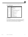
Station Manager Command Syntax . . . . . . . . . . . . . . . . . . . . . . . . . . . . . . . . .
4-10
Task Identification . . . . . . . . . . . . . . . . . . . . . . . . . . . . . . . . . . . . . . . . . . . . . . . .
4-10
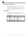
Display Data Representation . . . . . . . . . . . . . . . . . . . . . . . . . . . . . . . . . . . . . . .
4-11
Numeric Values . . . . . . . . . . . . . . . . . . . . . . . . . . . . . . . . . . . . . . . . . . . . . . .
4-11
Character Strings Values . . . . . . . . . . . . . . . . . . . . . . . . . . . . . . . . . . . . . . . .
4-11
Octet String Values . . . . . . . . . . . . . . . . . . . . . . . . . . . . . . . . . . . . . . . . . . . . .
4-11
Object Identifier Values . . . . . . . . . . . . . . . . . . . . . . . . . . . . . . . . . . . . . . . . .
4-11
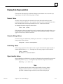
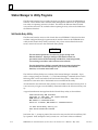
Station Manager in Utility Programs . . . . . . . . . . . . . . . . . . . . . . . . . . . . . . . . .
4-12
Soft Switch Entry Utility . . . . . . . . . . . . . . . . . . . . . . . . . . . . . . . . . . . . . . . .
4-12
Field Network Test Utility . . . . . . . . . . . . . . . . . . . . . . . . . . . . . . . . . . . . . . .
4-14
MMS–Ether net Communications for the Series 90–70 PLC User’s Manual – May
1994
viii
Contents
Section 3: Station Manager Command Descriptions . . . . . . . . . . .
GFK–0868
4-16
Command Input Processing . . . . . . . . . . . . . . . . . . . . . . . . . . . . . . . . . . . . .
4-16
ACB Command . . . . . . . . . . . . . . . . . . . . . . . . . . . . . . . . . . . . . . . . . . . . . . . .
4-17
BPS Command . . . . . . . . . . . . . . . . . . . . . . . . . . . . . . . . . . . . . . . . . . . . . . . .
4-17
CAP Command . . . . . . . . . . . . . . . . . . . . . . . . . . . . . . . . . . . . . . . . . . . . . . . .
4-18
CHBPS Command . . . . . . . . . . . . . . . . . . . . . . . . . . . . . . . . . . . . . . . . . . . . .
4-18
CHDATE Command . . . . . . . . . . . . . . . . . . . . . . . . . . . . . . . . . . . . . . . . . . .
4-18
CHLTIME Command . . . . . . . . . . . . . . . . . . . . . . . . . . . . . . . . . . . . . . . . . . .
4-19
CHSOSW Command . . . . . . . . . . . . . . . . . . . . . . . . . . . . . . . . . . . . . . . . . . .
4-19
CHTIME Command . . . . . . . . . . . . . . . . . . . . . . . . . . . . . . . . . . . . . . . . . . . .
4-21
CLEAR Command . . . . . . . . . . . . . . . . . . . . . . . . . . . . . . . . . . . . . . . . . . . . .
4-22
CLSOSW Command . . . . . . . . . . . . . . . . . . . . . . . . . . . . . . . . . . . . . . . . . . .
4-22
DATE Command . . . . . . . . . . . . . . . . . . . . . . . . . . . . . . . . . . . . . . . . . . . . . .
4-23
EXS Command . . . . . . . . . . . . . . . . . . . . . . . . . . . . . . . . . . . . . . . . . . . . . . . .
4-23
HELP Command . . . . . . . . . . . . . . . . . . . . . . . . . . . . . . . . . . . . . . . . . . . . . .
4-24
LOAD Command . . . . . . . . . . . . . . . . . . . . . . . . . . . . . . . . . . . . . . . . . . . . . .
4-25
LOG Command . . . . . . . . . . . . . . . . . . . . . . . . . . . . . . . . . . . . . . . . . . . . . . .
4-25
LOGIN Command . . . . . . . . . . . . . . . . . . . . . . . . . . . . . . . . . . . . . . . . . . . . .
4-26
LOGOUT Command . . . . . . . . . . . . . . . . . . . . . . . . . . . . . . . . . . . . . . . . . . .
4-27
LTIME Command . . . . . . . . . . . . . . . . . . . . . . . . . . . . . . . . . . . . . . . . . . . . . .
4-27
MDIB Command . . . . . . . . . . . . . . . . . . . . . . . . . . . . . . . . . . . . . . . . . . . . . .
4-28
NET Command . . . . . . . . . . . . . . . . . . . . . . . . . . . . . . . . . . . . . . . . . . . . . . . .
4-28
NODE Command . . . . . . . . . . . . . . . . . . . . . . . . . . . . . . . . . . . . . . . . . . . . . .
4-29
OK Command . . . . . . . . . . . . . . . . . . . . . . . . . . . . . . . . . . . . . . . . . . . . . . . . .
4-29
PI Command . . . . . . . . . . . . . . . . . . . . . . . . . . . . . . . . . . . . . . . . . . . . . . . . . .
4-29
REM Command . . . . . . . . . . . . . . . . . . . . . . . . . . . . . . . . . . . . . . . . . . . . . . .
4-30
REPORT Command . . . . . . . . . . . . . . . . . . . . . . . . . . . . . . . . . . . . . . . . . . . .
4-31
RESTART Command . . . . . . . . . . . . . . . . . . . . . . . . . . . . . . . . . . . . . . . . . . .
4-32
RIB Command . . . . . . . . . . . . . . . . . . . . . . . . . . . . . . . . . . . . . . . . . . . . . . . .
4-32
SHOW Command . . . . . . . . . . . . . . . . . . . . . . . . . . . . . . . . . . . . . . . . . . . . .
4-33
SOSW Command . . . . . . . . . . . . . . . . . . . . . . . . . . . . . . . . . . . . . . . . . . . . . .
4-36
STAT Command . . . . . . . . . . . . . . . . . . . . . . . . . . . . . . . . . . . . . . . . . . . . . . .
4-36
STOPT Command . . . . . . . . . . . . . . . . . . . . . . . . . . . . . . . . . . . . . . . . . . . . .
4-37
TALLY Command . . . . . . . . . . . . . . . . . . . . . . . . . . . . . . . . . . . . . . . . . . . . . .
4-37
TEST Command . . . . . . . . . . . . . . . . . . . . . . . . . . . . . . . . . . . . . . . . . . . . . . .
4-43
TIME Command . . . . . . . . . . . . . . . . . . . . . . . . . . . . . . . . . . . . . . . . . . . . . . .
4-44
TRACE Command . . . . . . . . . . . . . . . . . . . . . . . . . . . . . . . . . . . . . . . . . . . . .
4-45
VAR Command . . . . . . . . . . . . . . . . . . . . . . . . . . . . . . . . . . . . . . . . . . . . . . . .
4-47
VMD Command . . . . . . . . . . . . . . . . . . . . . . . . . . . . . . . . . . . . . . . . . . . . . . .
4-47
MMS–Ether net Communications for the Series 90–70 PLC User’s Manual – May
1994
ix
Contents
Chapter 5
Chapter 6
GFK–0868
General PLC Application Programming . . . . . . . . . . . . . . . . . . . . . .
5-1
Commands Supported Through Ladder Logic . . . . . . . . . . . . . . . . . . . . . . . .
5-1
Communications Commands . . . . . . . . . . . . . . . . . . . . . . . . . . . . . . . . . . . .
5-1
Station Manager Commands . . . . . . . . . . . . . . . . . . . . . . . . . . . . . . . . . . . .
5-2
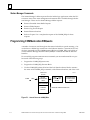
Programming COMMunication REQuests . . . . . . . . . . . . . . . . . . . . . . . . . . .
5-2
Using the COMM_REQ Instruction . . . . . . . . . . . . . . . . . . . . . . . . . . . . . . . . .
5-3
Device Independent Area . . . . . . . . . . . . . . . . . . . . . . . . . . . . . . . . . . . . . . .
5-3
Message Definition Block . . . . . . . . . . . . . . . . . . . . . . . . . . . . . . . . . . . . . . .
5-4
Programming a COMM_REQ . . . . . . . . . . . . . . . . . . . . . . . . . . . . . . . . . . . . . .
5-5
The LAN Interface Status Word . . . . . . . . . . . . . . . . . . . . . . . . . . . . . . . . . . . . .
5-7
Location of the LAN Interface Status Word . . . . . . . . . . . . . . . . . . . . . . . .
5-7
Contents of the LAN Interface Status Word . . . . . . . . . . . . . . . . . . . . . . . .
5-8
General Tips on Ladder Programming . . . . . . . . . . . . . . . . . . . . . . . . . . . . . . .
5-9
MMS COMMunications REQuests . . . . . . . . . . . . . . . . . . . . . . . . . . .
6-1
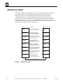
OSI Reference Model . . . . . . . . . . . . . . . . . . . . . . . . . . . . . . . . . . . . . . . . . . . . .
6-1
OSI Application Layer . . . . . . . . . . . . . . . . . . . . . . . . . . . . . . . . . . . . . . . . . .
6-1
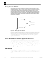
Message Flow in the OSI Model . . . . . . . . . . . . . . . . . . . . . . . . . . . . . . . . .
6-2
Series 90-70 Ethernet Interface Application Processes . . . . . . . . . . . . . . . . . .
6-2
MMS Responder . . . . . . . . . . . . . . . . . . . . . . . . . . . . . . . . . . . . . . . . . . . . . . .
6-2
Application Interface . . . . . . . . . . . . . . . . . . . . . . . . . . . . . . . . . . . . . . . . . . .
6-3
Selecting the Application Process . . . . . . . . . . . . . . . . . . . . . . . . . . . . . . . . . . .
6-4
Programming Communications COMM_REQs . . . . . . . . . . . . . . . . . . . . . . .
6-5
Association Control Block . . . . . . . . . . . . . . . . . . . . . . . . . . . . . . . . . . . . . . . . . .
6-7
General Association Status Bits . . . . . . . . . . . . . . . . . . . . . . . . . . . . . . . . . .
6-7
Request Completion . . . . . . . . . . . . . . . . . . . . . . . . . . . . . . . . . . . . . . . . . . .
6-8
Association Status Word . . . . . . . . . . . . . . . . . . . . . . . . . . . . . . . . . . . . . . . .
6-9
Association Status Word Extension . . . . . . . . . . . . . . . . . . . . . . . . . . . . . . .
6-10
MMS COMM_REQ Command Descriptions . . . . . . . . . . . . . . . . . . . . . . . . . .
6-11
Association Services . . . . . . . . . . . . . . . . . . . . . . . . . . . . . . . . . . . . . . . . . . . . . . .
6-11
Initiate Request Command - 8201 . . . . . . . . . . . . . . . . . . . . . . . . . . . . . . . .
6-11
Initiate Indication Service . . . . . . . . . . . . . . . . . . . . . . . . . . . . . . . . . . . . . . .
6-12
Examine Initiate Indication Command - 8202 . . . . . . . . . . . . . . . . . . . . . .
6-13
Initiate Response Command - 8203 . . . . . . . . . . . . . . . . . . . . . . . . . . . . . . .
6-15
Initiate Confirmation Service . . . . . . . . . . . . . . . . . . . . . . . . . . . . . . . . . . . .
6-16
Examine Positive Initiate Confirm Command - 8204 . . . . . . . . . . . . . . . .
6-17
Conclude Request Command - 8205 . . . . . . . . . . . . . . . . . . . . . . . . . . . . . .
6-18
Conclude Indication Service . . . . . . . . . . . . . . . . . . . . . . . . . . . . . . . . . . . . .
6-18
MMS–Ether net Communications for the Series 90–70 PLC User’s Manual – May
1994
x
Contents
GFK–0868
Conclude Response Command - 8206 . . . . . . . . . . . . . . . . . . . . . . . . . . . . .
6-19
Conclude Confirm Service . . . . . . . . . . . . . . . . . . . . . . . . . . . . . . . . . . . . . .
6-19
Abort Request Command - 8207 . . . . . . . . . . . . . . . . . . . . . . . . . . . . . . . . .
6-20
Abort Indication Service . . . . . . . . . . . . . . . . . . . . . . . . . . . . . . . . . . . . . . . .
6-20
Examine Association Options Command - 8300 . . . . . . . . . . . . . . . . . . . .
6-21
Memory Access Services . . . . . . . . . . . . . . . . . . . . . . . . . . . . . . . . . . . . . . . . . . .
6-24
Overview . . . . . . . . . . . . . . . . . . . . . . . . . . . . . . . . . . . . . . . . . . . . . . . . . . . . .
6-24
Read Request Command - 8322 . . . . . . . . . . . . . . . . . . . . . . . . . . . . . . . . . .
6-28
Read Indication Service . . . . . . . . . . . . . . . . . . . . . . . . . . . . . . . . . . . . . . . . .
6-30
Read Confirm Service . . . . . . . . . . . . . . . . . . . . . . . . . . . . . . . . . . . . . . . . . .
6-30
Write Request Command - 8323 . . . . . . . . . . . . . . . . . . . . . . . . . . . . . . . . . .
6-31
Write Indication Service . . . . . . . . . . . . . . . . . . . . . . . . . . . . . . . . . . . . . . . .
6-32
Write Confirm Service . . . . . . . . . . . . . . . . . . . . . . . . . . . . . . . . . . . . . . . . . .
6-33
InformationReport Request Command - 8320 . . . . . . . . . . . . . . . . . . . . . .
6-34
InformationReport Indication Service . . . . . . . . . . . . . . . . . . . . . . . . . . . . .
6-35
Examine InformationReport Indication Variable Command - 8321 . . . .
6-36
Transfer InformationReport Indication Data Command - 8330 . . . . . . . .
6-37
Discard InformationReport Indication Data Command - 8339 . . . . . . . .
6-38
Program Invocation Management Services . . . . . . . . . . . . . . . . . . . . . . . . . . .
6-39
PI Commands . . . . . . . . . . . . . . . . . . . . . . . . . . . . . . . . . . . . . . . . . . . . . . . . .
6-39
Start Request Command - 8304 . . . . . . . . . . . . . . . . . . . . . . . . . . . . . . . . . .
6-40
Start Indication Service . . . . . . . . . . . . . . . . . . . . . . . . . . . . . . . . . . . . . . . . .
6-41
Examine Start Indication Command - 8305 . . . . . . . . . . . . . . . . . . . . . . . .
6-41
Start Response Command - 8306 . . . . . . . . . . . . . . . . . . . . . . . . . . . . . . . . .
6-42
Stop Request Command - 8307 . . . . . . . . . . . . . . . . . . . . . . . . . . . . . . . . . .
6-43
Stop Indication Service . . . . . . . . . . . . . . . . . . . . . . . . . . . . . . . . . . . . . . . . .
6-43
Examine Stop Indication Command - 8308 . . . . . . . . . . . . . . . . . . . . . . . .
6-44
Stop Response Command - 8309 . . . . . . . . . . . . . . . . . . . . . . . . . . . . . . . . .
6-45
Reset Request Command - 8310 . . . . . . . . . . . . . . . . . . . . . . . . . . . . . . . . . .
6-46
Reset Indication Service . . . . . . . . . . . . . . . . . . . . . . . . . . . . . . . . . . . . . . . .
6-46
Examine Reset Indication Command - 8311 . . . . . . . . . . . . . . . . . . . . . . . .
6-47
Reset Response Command - 8312 . . . . . . . . . . . . . . . . . . . . . . . . . . . . . . . .
6-47
Resume Request Command - 8313 . . . . . . . . . . . . . . . . . . . . . . . . . . . . . . .
6-48
Resume Indication Service . . . . . . . . . . . . . . . . . . . . . . . . . . . . . . . . . . . . . .
6-49
Examine Resume Indication Command - 8314 . . . . . . . . . . . . . . . . . . . . .
6-49
Resume Response Command - 8315 . . . . . . . . . . . . . . . . . . . . . . . . . . . . . .
6-50
Set Local ProgramInvocation Processing - 8356 . . . . . . . . . . . . . . . . . . . . .
6-51
Set Local ProgramInvocation State Command - 8355 . . . . . . . . . . . . . . . .
6-52
Status Services . . . . . . . . . . . . . . . . . . . . . . . . . . . . . . . . . . . . . . . . . . . . . . . . . . .
6-53
MMS–Ether net Communications for the Series 90–70 PLC User’s Manual – May
1994
xi
Contents
Chapter 7
Chapter 8
GFK–0868
Status Request Command - 8250 . . . . . . . . . . . . . . . . . . . . . . . . . . . . . . . . .
6-53
Status Indication Service . . . . . . . . . . . . . . . . . . . . . . . . . . . . . . . . . . . . . . . .
6-54
Status Response Command - 8251 . . . . . . . . . . . . . . . . . . . . . . . . . . . . . . . .
6-54
Status Confirm Service . . . . . . . . . . . . . . . . . . . . . . . . . . . . . . . . . . . . . . . . .
6-55
Unsolicited Status Request - 8252 . . . . . . . . . . . . . . . . . . . . . . . . . . . . . . . .
6-55
Unsolicited Status Indication Service . . . . . . . . . . . . . . . . . . . . . . . . . . . . .
6-56
Examine UnsolicitedStatus Indication Command - 8253 . . . . . . . . . . . . .
6-56
Set Local VMD Status Command - 8353 . . . . . . . . . . . . . . . . . . . . . . . . . . .
6-57
Miscellaneous OSI Services . . . . . . . . . . . . . . . . . . . . . . . . . . . . . . . . . . . . . . . .
6-59
Identify Request Command - 8240 . . . . . . . . . . . . . . . . . . . . . . . . . . . . . . .
6-59
Identify Confirm Service . . . . . . . . . . . . . . . . . . . . . . . . . . . . . . . . . . . . . . . .
6-60
Cancel Request Command - 8290 . . . . . . . . . . . . . . . . . . . . . . . . . . . . . . . .
6-61
Get Remote Name List Command - 8301 . . . . . . . . . . . . . . . . . . . . . . . . . .
6-62
Error Request Command - 8350 . . . . . . . . . . . . . . . . . . . . . . . . . . . . . . . . . .
6-64
Reject Indication Service . . . . . . . . . . . . . . . . . . . . . . . . . . . . . . . . . . . . . . . .
6-65
Examine Reject Indication Command - 8351 . . . . . . . . . . . . . . . . . . . . . . .
6-65
Error Indication Service . . . . . . . . . . . . . . . . . . . . . . . . . . . . . . . . . . . . . . . . .
6-65
Examine Last Error Information Command - 8352 . . . . . . . . . . . . . . . . . .
6-66
Define Application Command - 8200 . . . . . . . . . . . . . . . . . . . . . . . . . . . . .
6-67
MMS Error Encodings . . . . . . . . . . . . . . . . . . . . . . . . . . . . . . . . . . . . . . . . . . . . .
6-68
Station Manager COMMunications REQuests . . . . . . . . . . . . . . . . .
7-1
Station Manager Ladder Requests . . . . . . . . . . . . . . . . . . . . . . . . . . . . . . . . . . .
7-1
Retrieve Extended Status Buffer Request - 8100 . . . . . . . . . . . . . . . . . . . .
7-2
Retrieve Tallies Request - 8101 . . . . . . . . . . . . . . . . . . . . . . . . . . . . . . . . . . .
7-4
Retrieve Log Events Request - 8102 . . . . . . . . . . . . . . . . . . . . . . . . . . . . . . .
7-6
Restart Ethernet Interface Request - 8103 . . . . . . . . . . . . . . . . . . . . . . . . .
7-7
Tuning and Configuring Stations for an Advanced Network . . . . .
8-1
Definition of an Advanced Network . . . . . . . . . . . . . . . . . . . . . . . . . . . . . . . . .
8-1
Using this Chapter . . . . . . . . . . . . . . . . . . . . . . . . . . . . . . . . . . . . . . . . . . . . . . . .
8-1
Configure a Station Screen . . . . . . . . . . . . . . . . . . . . . . . . . . . . . . . . . . . . . . . . .
8-2
Defining a Station . . . . . . . . . . . . . . . . . . . . . . . . . . . . . . . . . . . . . . . . . . . . . .
8-3
Selecting a Station . . . . . . . . . . . . . . . . . . . . . . . . . . . . . . . . . . . . . . . . . . . . .
8-4
Deleting a Station . . . . . . . . . . . . . . . . . . . . . . . . . . . . . . . . . . . . . . . . . . . . . .
8-4
MMS–Ether net Communications for the Series 90–70 PLC User’s Manual – May
1994
xii
Contents
Section 1: Configuring a Series 90-70 PLC Station . . . . . . . . . . . . .
Configuration Editor Main Menu for the Series 90-70 PLC . . . . . . . . . . . . . .
Saving Changes Before Exiting the Configuration Editor Main Menu . .
Menu Structure . . . . . . . . . . . . . . . . . . . . . . . . . . . . . . . . . . . . . . . . . . . . . . . .
8-5
8-6
8-6
ISO Parameters Menu . . . . . . . . . . . . . . . . . . . . . . . . . . . . . . . . . . . . . . . . . . . . .
8-7
Data Link Parameters Screen . . . . . . . . . . . . . . . . . . . . . . . . . . . . . . . . . . . . . . .
8-8
Network Layer Parameters Screen . . . . . . . . . . . . . . . . . . . . . . . . . . . . . . . . . .
8-10
Network Layer RIB Table Screen . . . . . . . . . . . . . . . . . . . . . . . . . . . . . . . . . . . .
8-12
Transport / Session Layer Parameters Screen . . . . . . . . . . . . . . . . . . . . . . . . . .
8-14
Application Processes Screen . . . . . . . . . . . . . . . . . . . . . . . . . . . . . . . . . . . . . . .
8-16
Abstract and Transfer Syntaxes Screen . . . . . . . . . . . . . . . . . . . . . . . . . . . . . . .
8-18
Association Parameters Screen . . . . . . . . . . . . . . . . . . . . . . . . . . . . . . . . . . . . . .
8-19
Local Application DIB Screen . . . . . . . . . . . . . . . . . . . . . . . . . . . . . . . . . . . . . . .
8-20
MMS Parameters Menu . . . . . . . . . . . . . . . . . . . . . . . . . . . . . . . . . . . . . . . . . . .
8-21
Variable Names Screen . . . . . . . . . . . . . . . . . . . . . . . . . . . . . . . . . . . . . . . . . . . .
8-22
Maximum MMS Message Size Screen . . . . . . . . . . . . . . . . . . . . . . . . . . . . . . . .
8-24
System Parameters Screen . . . . . . . . . . . . . . . . . . . . . . . . . . . . . . . . . . . . . . . . .
8-25
Print File Screen . . . . . . . . . . . . . . . . . . . . . . . . . . . . . . . . . . . . . . . . . . . . . . . . . .
8-28
Section 2: Configuring Network-Wide Parameters . . . . . . . . . . . .
Chapter 9
Appendix A
GFK–0868
8-5
8-29
Configure Network-Wide Parameters Menu . . . . . . . . . . . . . . . . . . . . . . . . . .
8-29
Load Group Parameters Screen . . . . . . . . . . . . . . . . . . . . . . . . . . . . . . . . . . . . .
8-30
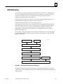
Troubleshooting . . . . . . . . . . . . . . . . . . . . . . . . . . . . . . . . . . . . . . . . . . .
9-1
Overview . . . . . . . . . . . . . . . . . . . . . . . . . . . . . . . . . . . . . . . . . . . . . . . . . . . . . . .
9-1
Using this Chapter . . . . . . . . . . . . . . . . . . . . . . . . . . . . . . . . . . . . . . . . . . . . . . . .
9-2
What to do if you Cannot Solve the Problem . . . . . . . . . . . . . . . . . . . . . . . . .
9-4
The Power-up State . . . . . . . . . . . . . . . . . . . . . . . . . . . . . . . . . . . . . . . . . . . . . . .
9-5
The Soft Switch Entry State . . . . . . . . . . . . . . . . . . . . . . . . . . . . . . . . . . . . . . . .
9-5
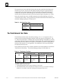
The Field Network Test State . . . . . . . . . . . . . . . . . . . . . . . . . . . . . . . . . . . . . . .
9-6
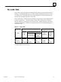
The Loader State . . . . . . . . . . . . . . . . . . . . . . . . . . . . . . . . . . . . . . . . . . . . . . . . .
9-7
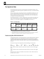
The Operational State . . . . . . . . . . . . . . . . . . . . . . . . . . . . . . . . . . . . . . . . . . . . .
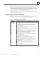
Troubleshooting When STATUS OK LED is OFF . . . . . . . . . . . . . . . . . . . .
Troubleshooting When the STATUS OK LED is ON . . . . . . . . . . . . . . . . .
Exception Log Event Error Codes . . . . . . . . . . . . . . . . . . . . . . . . . . . . . . . .
Extended Status Buffer Negative Values . . . . . . . . . . . . . . . . . . . . . . . . . .
Extended Status Buffer Errors . . . . . . . . . . . . . . . . . . . . . . . . . . . . . . . . . . .
9-8
9-8
9-9
9-10
9-27
9-27
GEnet LAN Interface Status Word . . . . . . . . . . . . . . . . . . . . . . . . . . . . . . . . . .
9-30
Glossary of Terms . . . . . . . . . . . . . . . . . . . . . . . . . . . . . . . . . . . . . . . . . .
A-1
Commonly Used Acronyms and Abbreviations . . . . . . . . . . . . . . . . . . . . . . .
A-1
Glossary of Terms . . . . . . . . . . . . . . . . . . . . . . . . . . . . . . . . . . . . . . . . . . . . . . . . .
A-3
MMS–Ether net Communications for the Series 90–70 PLC User’s Manual – May
1994
xiii
Contents
Appendix B
Appendix C
Appendix D
GFK–0868
ISO Networking Concepts . . . . . . . . . . . . . . . . . . . . . . . . . . . . . . . . . .
B-1
OSI Reference Model . . . . . . . . . . . . . . . . . . . . . . . . . . . . . . . . . . . . . . . . . . . . .
B-2
Protocols Used for GE Fanuc Control Devices . . . . . . . . . . . . . . . . . . . . . .
B-3
Implementation of the OSI Model in GE Fanuc Control Devices . . . . . .
B-4
Mapping MMS Services to ACSE and Presentation Services . . . . . . . . . .
B-4
OSI Addressing . . . . . . . . . . . . . . . . . . . . . . . . . . . . . . . . . . . . . . . . . . . . . . . . . . .
B-5
Protocol Data Transfer . . . . . . . . . . . . . . . . . . . . . . . . . . . . . . . . . . . . . . . . . . . . .
B-6
OSI Application Layer . . . . . . . . . . . . . . . . . . . . . . . . . . . . . . . . . . . . . . . . . . . . .
B-7
Locating Applications . . . . . . . . . . . . . . . . . . . . . . . . . . . . . . . . . . . . . . . . . . . . .
B-10
The Client–Server Model . . . . . . . . . . . . . . . . . . . . . . . . . . . . . . . . . . . . . . . . . .
B-10
MMS Objects and Their Attributes . . . . . . . . . . . . . . . . . . . . . . . . . . . . . . . . . .
B-11
Object Scope . . . . . . . . . . . . . . . . . . . . . . . . . . . . . . . . . . . . . . . . . . . . . . . . . .
The Virtual Manufacturing Device (VMD) Object . . . . . . . . . . . . . . . . . . .
B-12
B-12
Capability Objects . . . . . . . . . . . . . . . . . . . . . . . . . . . . . . . . . . . . . . . . . . . . .
B-17
Domain Objects . . . . . . . . . . . . . . . . . . . . . . . . . . . . . . . . . . . . . . . . . . . . . . .
B-17
Program Invocation Objects . . . . . . . . . . . . . . . . . . . . . . . . . . . . . . . . . . . . .
Variable Objects . . . . . . . . . . . . . . . . . . . . . . . . . . . . . . . . . . . . . . . . . . . . . . .
B-21
B-24
Operator Station Objects (CNC Only) . . . . . . . . . . . . . . . . . . . . . . . . . . . .
B-25
MMS Variable Mapping (Series 90-70 PLC Only) . . . . . . . . . . . . . . . . . . . . . .
B-27
Boolean Data . . . . . . . . . . . . . . . . . . . . . . . . . . . . . . . . . . . . . . . . . . . . . . . . . .
Bit String Data . . . . . . . . . . . . . . . . . . . . . . . . . . . . . . . . . . . . . . . . . . . . . . . . .
B-27
B-28
Signed and Unsigned Integers . . . . . . . . . . . . . . . . . . . . . . . . . . . . . . . . . . .
B-29
Floating Point . . . . . . . . . . . . . . . . . . . . . . . . . . . . . . . . . . . . . . . . . . . . . . . . .
B-29
Octet Strings and Visible Strings . . . . . . . . . . . . . . . . . . . . . . . . . . . . . . . . .
Object Scope . . . . . . . . . . . . . . . . . . . . . . . . . . . . . . . . . . . . . . . . . . . . . . . . . .
B-29
B-29
Series 90-70 PLC Application . . . . . . . . . . . . . . . . . . . . . . . . . . . . . . . . . . . .
B-30
Naming and Addressing . . . . . . . . . . . . . . . . . . . . . . . . . . . . . . . . . . . . . . . .
B-30
Protocol Implementation Conformance Statement (PICS) . . . . . . .
C-1
PICS for the Manufacturing Message Specification (MMS) . . . . . . . . . . . . . .
C-1
Communication Ports Characteristics . . . . . . . . . . . . . . . . . . . . . . . . .
D-1
Serial Port for Local GSM Communications . . . . . . . . . . . . . . . . . . . . . . . . . . .
D-2
Serial Port Settings . . . . . . . . . . . . . . . . . . . . . . . . . . . . . . . . . . . . . . . . . . . . .
D-2
Serial Port Pinouts . . . . . . . . . . . . . . . . . . . . . . . . . . . . . . . . . . . . . . . . . . . . .
Serial Cable . . . . . . . . . . . . . . . . . . . . . . . . . . . . . . . . . . . . . . . . . . . . . . . . . . .
D-2
D-2
Display Terminal Settings . . . . . . . . . . . . . . . . . . . . . . . . . . . . . . . . . . . . . . .
D-3
The AUI Port for the Ethernet Interface . . . . . . . . . . . . . . . . . . . . . . . . . . . . . .
D-4
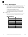
Ethernet AUI Port Pinouts . . . . . . . . . . . . . . . . . . . . . . . . . . . . . . . . . . . . . . .
AUI (Transceiver Cable) . . . . . . . . . . . . . . . . . . . . . . . . . . . . . . . . . . . . . . . . .
D-4
D-5
Transceiver Description . . . . . . . . . . . . . . . . . . . . . . . . . . . . . . . . . . . . . . . . .
D-6
MMS–Ether net Communications for the Series 90–70 PLC User’s Manual – May
1994
xiv
Contents
Appendix E
Appendix F
Appendix G
Appendix H
Soft Switch Parameters . . . . . . . . . . . . . . . . . . . . . . . . . . . . . . . . . . . . .
E-1
Station Address . . . . . . . . . . . . . . . . . . . . . . . . . . . . . . . . . . . . . . . . . . . . . . . . . . .
E-1
Load Source . . . . . . . . . . . . . . . . . . . . . . . . . . . . . . . . . . . . . . . . . . . . . . . . . . . . .
E-2
LAN Online . . . . . . . . . . . . . . . . . . . . . . . . . . . . . . . . . . . . . . . . . . . . . . . . . . . . .
E-2
Backplane Online . . . . . . . . . . . . . . . . . . . . . . . . . . . . . . . . . . . . . . . . . . . . . . . . .
E-2
Network Load Address . . . . . . . . . . . . . . . . . . . . . . . . . . . . . . . . . . . . . . . . . . . .
E-2
Modify Soft Switch Settings . . . . . . . . . . . . . . . . . . . . . . . . . . . . . . . . . . . . . . . .
E-3
Configuring Soft Switch Parameters . . . . . . . . . . . . . . . . . . . . . . . . . . . . . . . . .
E-4
Configuring Soft Switch Parameters Using the GSM . . . . . . . . . . . . . . . .
E-4
Correct Results of Soft Switch Configuration . . . . . . . . . . . . . . . . . . . . . . .
E-5
Station Configuration Parameters . . . . . . . . . . . . . . . . . . . . . . . . . . . .
F-1
Configuration Parameters via the Station Manager . . . . . . . . . . . . . . . . . . . .
F-1
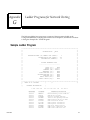
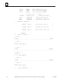
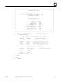
Ladder Programs for Network Testing . . . . . . . . . . . . . . . . . . . . . . . .
G-1
Sample Ladder Program . . . . . . . . . . . . . . . . . . . . . . . . . . . . . . . . . . . . . . . . . . .
G-1
Sample DOS System Files . . . . . . . . . . . . . . . . . . . . . . . . . . . . . . . . . .
H-1
Sample DOS Initialization Files . . . . . . . . . . . . . . . . . . . . . . . . . . . . . . . . . . . . .
H-2
3Com Etherlink II . . . . . . . . . . . . . . . . . . . . . . . . . . . . . . . . . . . . . . . . . . . . . .
H-2
3Com Etherlink 16 . . . . . . . . . . . . . . . . . . . . . . . . . . . . . . . . . . . . . . . . . . . . .
H-3
3Com Etherlink /MC . . . . . . . . . . . . . . . . . . . . . . . . . . . . . . . . . . . . . . . . . . .
H-4
Western Digital EtherCard PLUS, EtherCard PLUS Elite 16, EtherCard PLUS/A .
H-5
Intel 82593 . . . . . . . . . . . . . . . . . . . . . . . . . . . . . . . . . . . . . . . . . . . . . . . . . . . .
H-6
Xircom Pocket Adapter . . . . . . . . . . . . . . . . . . . . . . . . . . . . . . . . . . . . . . . . .
H-7
SMC EtherCard PLUS, EtherCard PLUS Elite 16, EtherCard PLUS/A. . .
H-8
Optimizing the GSM for Network Operation . . . . . . . . . . . . . . . . . . . . . . . . .
H-9
Appendix I
Forms . . . . . . . . . . . . . . . . . . . . . . . . . . . . . . . . . . . . . . . . . . . . . . . . . . . .
I-1
Appendix J
GEnet System Manager Data Link Error Codes . . . . . . . . . . . . . . . .
J-1
GFK–0868
MMS–Ether net Communications for the Series 90–70 PLC User’s Manual – May
1994
xv
Contents
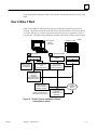
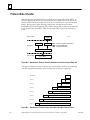
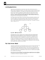
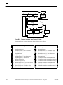
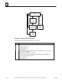
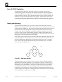
Figure 1-1. Major Components of the GEnet 802.3 LANN . . . . . . . . . . . . . . . . . . . . . . . . . . . . . . . . . . . .
1-1
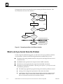
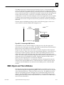
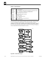
Figure 1-2. The Main Tasks for Installing the Ethernet
Communications System . . . . . . . . . . . . . . . . . . . . . . . . . . . . . . . . . . . . . . . . . . . .
1-5
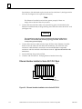
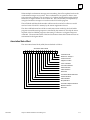
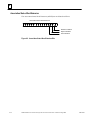
Figure 2-1. Ethernet Controller Board . . . . . . . . . . . . . . . . . . . . . . . . . . . . . . . . . . . . . . . . . . . . . . . . . . . . .
2-2
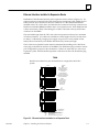
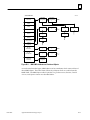
Figure 2-2. Ethernet Controller Installation in the Series 90-70 PLC . . . . . . . . . . . . . . . . . . . . . . . . . . . .
2-6
Figure 2-3. Ethernet Interface Installation in an Expansion Rack . . . . . . . . . . . . . . . . . . . . . . . . . . . . . .
2-7
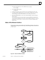
Figure 2-4. States of the Ethernet Interface . . . . . . . . . . . . . . . . . . . . . . . . . . . . . . . . . . . . . . . . . . . . . . . . .
2-9
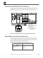
Figure 3-1. GEnet System Manager (GSM) on 802.3 LAN . . . . . . . . . . . . . . . . . . . . . . . . . . . . . . . . . . . .
3-1
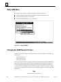
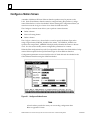
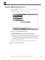
Figure 3-2. GSM Main Menu . . . . . . . . . . . . . . . . . . . . . . . . . . . . . . . . . . . . . . . . . . . . . . . . . . . . . . . . . . . . .
3-13
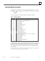
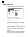
Figure 3-3. GSM Menu Structure . . . . . . . . . . . . . . . . . . . . . . . . . . . . . . . . . . . . . . . . . . . . . . . . . . . . . . . . .
3-16
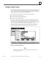
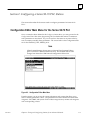
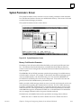
Figure 3-4. Configure a Station Screen . . . . . . . . . . . . . . . . . . . . . . . . . . . . . . . . . . . . . . . . . . . . . . . . . . . .
3-19
Figure 3-5. Configuration Editor Menu . . . . . . . . . . . . . . . . . . . . . . . . . . . . . . . . . . . . . . . . . . . . . . . . . . . .
3-23
Figure 3-6. ISO Parameters Menu . . . . . . . . . . . . . . . . . . . . . . . . . . . . . . . . . . . . . . . . . . . . . . . . . . . . . . . .
3-25
Figure 3-7. Network Layer Parameters Screen . . . . . . . . . . . . . . . . . . . . . . . . . . . . . . . . . . . . . . . . . . . . . .
3-26
Figure 3-8. Transport/Session Layer Parameters Screen . . . . . . . . . . . . . . . . . . . . . . . . . . . . . . . . . . . . . .
3-27
Figure 3-9. Application Processes Screen . . . . . . . . . . . . . . . . . . . . . . . . . . . . . . . . . . . . . . . . . . . . . . . . . . .
3-28
Figure 3-10. Local Application DIB Screen . . . . . . . . . . . . . . . . . . . . . . . . . . . . . . . . . . . . . . . . . . . . . . . . .
3-30
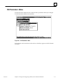
Figure 3-11. MMS Parameters Menu . . . . . . . . . . . . . . . . . . . . . . . . . . . . . . . . . . . . . . . . . . . . . . . . . . . . . .
3-31
Figure 3-12. Variable Names Screen . . . . . . . . . . . . . . . . . . . . . . . . . . . . . . . . . . . . . . . . . . . . . . . . . . . . . . .
3-32
Figure 3-13. Print File Screen . . . . . . . . . . . . . . . . . . . . . . . . . . . . . . . . . . . . . . . . . . . . . . . . . . . . . . . . . . . . .
3-34
Figure 3-14. Foreign Device Configuration Editor Menu . . . . . . . . . . . . . . . . . . . . . . . . . . . . . . . . . . . . .
3-36
Figure 3-15. Foreign Application Processes Screen . . . . . . . . . . . . . . . . . . . . . . . . . . . . . . . . . . . . . . . . . .
3-37
Figure 3-16. Download Station Screen . . . . . . . . . . . . . . . . . . . . . . . . . . . . . . . . . . . . . . . . . . . . . . . . . . . . .
3-39
Figure 3-17. Access Station Manager Screen . . . . . . . . . . . . . . . . . . . . . . . . . . . . . . . . . . . . . . . . . . . . . . . .
3-42
Figure 3-18. List All Stations Screen . . . . . . . . . . . . . . . . . . . . . . . . . . . . . . . . . . . . . . . . . . . . . . . . . . . . . . .
3-43
Figure 3-19. List All Configured Applications Menu . . . . . . . . . . . . . . . . . . . . . . . . . . . . . . . . . . . . . . . . .
3-44
Figure 3-20. 7-Layer Application DIB Screen . . . . . . . . . . . . . . . . . . . . . . . . . . . . . . . . . . . . . . . . . . . . . . .
3-45
Figure 3-21. Setup GSM Menu . . . . . . . . . . . . . . . . . . . . . . . . . . . . . . . . . . . . . . . . . . . . . . . . . . . . . . . . . . .
3-46
Figure 4-1. Station Manager Accessed Locally through the 9–pin Serial Port by a GSM
in Local Station Manager Mode (or an ASCII Terminal) . . . . . . . . . . . . . . . . . .
4-2
Figure 4-2. Station Manager Accessed Directly over the Network by a GSM
in Network Station Manager Mode . . . . . . . . . . . . . . . . . . . . . . . . . . . . . . . . . . .
4-2
Figure 4-3. Station Manager Accessed Remotely over the Network by a
GSM in Local Station Manager Mode using the REM (Remote) Command . .
4-3
Figure 5-1. General Format for COMM_REQs . . . . . . . . . . . . . . . . . . . . . . . . . . . . . . . . . . . . . . . . . . . . . .
5-2
Figure 6-1. Message Types, Time Sequence . . . . . . . . . . . . . . . . . . . . . . . . . . . . . . . . . . . . . . . . . . . . . . . . .
6-2
Figure 6-2. Association Status Word Extension Bits . . . . . . . . . . . . . . . . . . . . . . . . . . . . . . . . . . . . . . . . . .
6-10
Figure 8-1. Configure a Station Screen . . . . . . . . . . . . . . . . . . . . . . . . . . . . . . . . . . . . . . . . . . . . . . . . . . . .
8-2
Figure 8-2. Configuration Editor Main Menu . . . . . . . . . . . . . . . . . . . . . . . . . . . . . . . . . . . . . . . . . . . . . . .
8-5
GFK–0868
MMS–Ether net Communications for the Series 90–70 PLC User’s Manual – May
1994
xvi
Contents
Figure 8-3. ISO Parameters Menu . . . . . . . . . . . . . . . . . . . . . . . . . . . . . . . . . . . . . . . . . . . . . . . . . . . . . . . .
8-7
Figure 8-4. Data Link Parameters Screen . . . . . . . . . . . . . . . . . . . . . . . . . . . . . . . . . . . . . . . . . . . . . . . . . .
8-8
Figure 8-5. Network Layer Parameters Screen . . . . . . . . . . . . . . . . . . . . . . . . . . . . . . . . . . . . . . . . . . . . . .
8-10
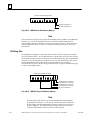
Figure 8-6. Network Layer RIB Table Screen . . . . . . . . . . . . . . . . . . . . . . . . . . . . . . . . . . . . . . . . . . . . . . .
8-12
Figure 8-7. Specifying Automatic or Static Routing . . . . . . . . . . . . . . . . . . . . . . . . . . . . . . . . . . . . . . . . . .
8-13
Figure 8-8. Transport/Session Layer Parameters Screen . . . . . . . . . . . . . . . . . . . . . . . . . . . . . . . . . . . . . .
8-14
Figure 8-9. Application Processes Screen . . . . . . . . . . . . . . . . . . . . . . . . . . . . . . . . . . . . . . . . . . . . . . . . . . .
8-16
Figure 8-10. Abstract and Transfer Syntaxes Screen . . . . . . . . . . . . . . . . . . . . . . . . . . . . . . . . . . . . . . . . . .
8-18
Figure 8-11. Association Parameters Screen . . . . . . . . . . . . . . . . . . . . . . . . . . . . . . . . . . . . . . . . . . . . . . . .
8-19
Figure 8-12. Local Application DIB Screen . . . . . . . . . . . . . . . . . . . . . . . . . . . . . . . . . . . . . . . . . . . . . . . . .
8-20
Figure 8-13. MMS Parameters Menu . . . . . . . . . . . . . . . . . . . . . . . . . . . . . . . . . . . . . . . . . . . . . . . . . . . . . .
8-21
Figure 8-14. Variable Names Screen . . . . . . . . . . . . . . . . . . . . . . . . . . . . . . . . . . . . . . . . . . . . . . . . . . . . . . .
8-22
Figure 8-15. Maximum MMS Message Size Screen . . . . . . . . . . . . . . . . . . . . . . . . . . . . . . . . . . . . . . . . . .
8-24
Figure 8-16. System Parameters Screen . . . . . . . . . . . . . . . . . . . . . . . . . . . . . . . . . . . . . . . . . . . . . . . . . . . .
8-25
Figure 8-17. Print File Screen . . . . . . . . . . . . . . . . . . . . . . . . . . . . . . . . . . . . . . . . . . . . . . . . . . . . . . . . . . . . .
8-28
Figure 8-18. Configure Network-Wide Parameters Menu . . . . . . . . . . . . . . . . . . . . . . . . . . . . . . . . . . . .
8-29
Figure 8-19. Load Group Parameters Screen . . . . . . . . . . . . . . . . . . . . . . . . . . . . . . . . . . . . . . . . . . . . . . .
8-30
Figure 9-1. Determining the State of the Ethernet Interface . . . . . . . . . . . . . . . . . . . . . . . . . . . . . . . . . .
9-4
Figure 9-2. Meaning of GEnet LAN Interface Status Inputs . . . . . . . . . . . . . . . . . . . . . . . . . . . . . . . . . . .
9-30
Figure B-1. OSI-Reference Model . . . . . . . . . . . . . . . . . . . . . . . . . . . . . . . . . . . . . . . . . . . . . . . . . . . . . . . . .
B-2
Figure B-2. Relationship between Tasks and Layers of GE Fanuc Control Devices . . . . . . . . . . . . . . .
B-4
Figure B-3. Service Access Points for the OSI Layers . . . . . . . . . . . . . . . . . . . . . . . . . . . . . . . . . . . . . . . . .
B-5
Figure B-4. Attachment of Protocol Control Information to form the Protocol Data Unit . . . . . . . . . .
B-6
Figure B-5. Attachment of Protocol Control Information throughout the ISO Stack . . . . . . . . . . . . . .
B-6
Figure B-6. Application Process Concept . . . . . . . . . . . . . . . . . . . . . . . . . . . . . . . . . . . . . . . . . . . . . . . . . . .
B-8
Figure B-7. Series 90-70 PLC Application Process Implementation . . . . . . . . . . . . . . . . . . . . . . . . . . . . .
B-8
Figure B-8. CNC Application Process Implementation . . . . . . . . . . . . . . . . . . . . . . . . . . . . . . . . . . . . . . .
B-9
Figure B-9. MMS Object Identifier . . . . . . . . . . . . . . . . . . . . . . . . . . . . . . . . . . . . . . . . . . . . . . . . . . . . . . . .
B-10
Figure B-10. Acknowledged MMS Service . . . . . . . . . . . . . . . . . . . . . . . . . . . . . . . . . . . . . . . . . . . . . . . . .
B-11
Figure B-11. MMS VMD Attributes and Contained Objects . . . . . . . . . . . . . . . . . . . . . . . . . . . . . . . . . . .
B-13
Figure B-12. Domain State Diagram . . . . . . . . . . . . . . . . . . . . . . . . . . . . . . . . . . . . . . . . . . . . . . . . . . . . . .
B-18
Figure B-13. Program Invocation State Diagram (PI State) . . . . . . . . . . . . . . . . . . . . . . . . . . . . . . . . . . . .
B-22
Figure B-14. Operator Station State Diagram . . . . . . . . . . . . . . . . . . . . . . . . . . . . . . . . . . . . . . . . . . . . . . .
B-26
Figure B-15. MMS Boolean Data Memory Mapping . . . . . . . . . . . . . . . . . . . . . . . . . . . . . . . . . . . . . . . . .
B-28
Figure B-16. MMS Bit String Data Memory Mapping . . . . . . . . . . . . . . . . . . . . . . . . . . . . . . . . . . . . . . . .
B-28
Figure B-17. MMS Object Identifier . . . . . . . . . . . . . . . . . . . . . . . . . . . . . . . . . . . . . . . . . . . . . . . . . . . . . . .
B-30
Figure D-1. Serial Cable to Connect GSM (25–Pin Connector) to Ethernet Interface . . . . . . . . . . . . . .
D-2
Figure D-2. Serial Cable to Connect GSM (9–Pin Connector) to Ethernet Interface . . . . . . . . . . . . . . .
D-3
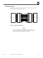
Figure D-3. Transceiver Cable Connection . . . . . . . . . . . . . . . . . . . . . . . . . . . . . . . . . . . . . . . . . . . . . . . . .
D-5
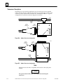
Figure D-4. 10Base2 Transceiver Configuration . . . . . . . . . . . . . . . . . . . . . . . . . . . . . . . . . . . . . . . . . . . . .
D-6
Figure D-5. 10Base5 Transceiver Configuration . . . . . . . . . . . . . . . . . . . . . . . . . . . . . . . . . . . . . . . . . . . . .
D-6
GFK–0868
MMS–Ether net Communications for the Series 90–70 PLC User’s Manual – May
1994
xvii
Contents
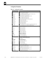
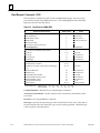
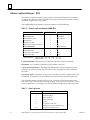
Table 2-1. Ethernet Controller Board Indicators . . . . . . . . . . . . . . . . . . . . . . . . . . . . . . . . . . . . . . . . . . . . .
2-3
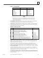
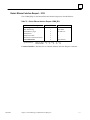
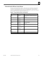
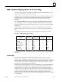
Table 3-1. 802.3/Ethernet Cards for the PC . . . . . . . . . . . . . . . . . . . . . . . . . . . . . . . . . . . . . . . . . . . . . . . . .
3-5
Table 3-2. Default PC Hardware Settings for 802.3/Ethernet Cards . . . . . . . . . . . . . . . . . . . . . . . . . . . .
3-6
Table 3-3. GSM Keyboard Functions (Alt-K) . . . . . . . . . . . . . . . . . . . . . . . . . . . . . . . . . . . . . . . . . . . . . . . .
3-15
Table 4-1. Monitor Commands . . . . . . . . . . . . . . . . . . . . . . . . . . . . . . . . . . . . . . . . . . . . . . . . . . . . . . . . . . .
4-7
Table 4-2. Modify Commands . . . . . . . . . . . . . . . . . . . . . . . . . . . . . . . . . . . . . . . . . . . . . . . . . . . . . . . . . . . .
4-9
Table 4-3. Task Identifiers . . . . . . . . . . . . . . . . . . . . . . . . . . . . . . . . . . . . . . . . . . . . . . . . . . . . . . . . . . . . . . . .
4-10
Table 4-4. Soft Switch Entry Utility Commands . . . . . . . . . . . . . . . . . . . . . . . . . . . . . . . . . . . . . . . . . . . . .
4-13
Table 4-5. Field Network Test Utility Commands . . . . . . . . . . . . . . . . . . . . . . . . . . . . . . . . . . . . . . . . . . . .
4-15
Table 4-6. Control Characters . . . . . . . . . . . . . . . . . . . . . . . . . . . . . . . . . . . . . . . . . . . . . . . . . . . . . . . . . . . .
4-16
Table 4-7. Load Source Parameters . . . . . . . . . . . . . . . . . . . . . . . . . . . . . . . . . . . . . . . . . . . . . . . . . . . . . . . .
4-20
Table 4-8. Soft Switch Default Values for the Ethernet Interface . . . . . . . . . . . . . . . . . . . . . . . . . . . . . . .
4-21
Table 4-9. Exception Log Event Definitions . . . . . . . . . . . . . . . . . . . . . . . . . . . . . . . . . . . . . . . . . . . . . . . . .
4-26
Table 4-10. Configuration Parameters . . . . . . . . . . . . . . . . . . . . . . . . . . . . . . . . . . . . . . . . . . . . . . . . . . . . .
4-34
Table 4-11. Application Layer Tallies (Tally a) . . . . . . . . . . . . . . . . . . . . . . . . . . . . . . . . . . . . . . . . . . . . . . .
4-37
Table 4-12. System Memory Tallies (Tally b) . . . . . . . . . . . . . . . . . . . . . . . . . . . . . . . . . . . . . . . . . . . . . . . .
4-38
Table 4-13. PLC Driver Tallies (Tally c) . . . . . . . . . . . . . . . . . . . . . . . . . . . . . . . . . . . . . . . . . . . . . . . . . . . . .
4-38
Table 4-14. Distributed Directory Protocol (DDP) Tallies (Tally d) . . . . . . . . . . . . . . . . . . . . . . . . . . . . . .
4-38
Table 4-15. ACSE Tallies (Tally e) . . . . . . . . . . . . . . . . . . . . . . . . . . . . . . . . . . . . . . . . . . . . . . . . . . . . . . . . . .
4-39
Table 4-16. Data Link Tallies (part of Tally l) . . . . . . . . . . . . . . . . . . . . . . . . . . . . . . . . . . . . . . . . . . . . . . . .
4-39
Table 4-17. MAC Layer Tallies (part of Tally l) . . . . . . . . . . . . . . . . . . . . . . . . . . . . . . . . . . . . . . . . . . . . . . .
4-40
Table 4-18. MMS Provider Tallies (Tally m) . . . . . . . . . . . . . . . . . . . . . . . . . . . . . . . . . . . . . . . . . . . . . . . . .
4-40
Table 4-19. Network Layer Tallies (Tally n) . . . . . . . . . . . . . . . . . . . . . . . . . . . . . . . . . . . . . . . . . . . . . . . . .
4-41
Table 4-20. Presentation Layer Tallies (Tally p) . . . . . . . . . . . . . . . . . . . . . . . . . . . . . . . . . . . . . . . . . . . . . .
4-41
Table 4-21. Session Layer Tallies (Tally s) . . . . . . . . . . . . . . . . . . . . . . . . . . . . . . . . . . . . . . . . . . . . . . . . . . .
4-41
Table 4-22. Transport Layer Tallies (Tally t) . . . . . . . . . . . . . . . . . . . . . . . . . . . . . . . . . . . . . . . . . . . . . . . . .
4-42
Table 4-23. SRTP Service Agent Tallies (Tally v) . . . . . . . . . . . . . . . . . . . . . . . . . . . . . . . . . . . . . . . . . . . . .
4-42
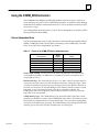
Table 5-1. Format of the COMM_REQ Device Independent Area . . . . . . . . . . . . . . . . . . . . . . . . . . . . . .
5-3
Table 5-2. Values for the CRSW Memory Type . . . . . . . . . . . . . . . . . . . . . . . . . . . . . . . . . . . . . . . . . . . . . .
5-4
Table 5-3. CRSW Interpretation . . . . . . . . . . . . . . . . . . . . . . . . . . . . . . . . . . . . . . . . . . . . . . . . . . . . . . . . . .
5-4
Table 5-4. Block Move Instruction Operands . . . . . . . . . . . . . . . . . . . . . . . . . . . . . . . . . . . . . . . . . . . . . . .
5-6
Table 5-5. The LAN Interface Status Word . . . . . . . . . . . . . . . . . . . . . . . . . . . . . . . . . . . . . . . . . . . . . . . . .
5-8
Table 6-1. Example Application Common Names . . . . . . . . . . . . . . . . . . . . . . . . . . . . . . . . . . . . . . . . . . .
6-4
Table 6-2. PLC Communications Commands . . . . . . . . . . . . . . . . . . . . . . . . . . . . . . . . . . . . . . . . . . . . . . .
6-6
Table 6-3. Association Control Block . . . . . . . . . . . . . . . . . . . . . . . . . . . . . . . . . . . . . . . . . . . . . . . . . . . . . .
6-7
Table 6-4. Initiate Request COMM_REQ . . . . . . . . . . . . . . . . . . . . . . . . . . . . . . . . . . . . . . . . . . . . . . . . . . .
6-11
Table 6-5. Examine Initiate Indication COMM_REQ . . . . . . . . . . . . . . . . . . . . . . . . . . . . . . . . . . . . . . . . .
6-13
GFK–0868
MMS–Ether net Communications for the Series 90–70 PLC User’s Manual – May
1994
xviii
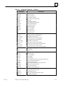
Contents
Table 6-6. Examine Initiate Indication Data . . . . . . . . . . . . . . . . . . . . . . . . . . . . . . . . . . . . . . . . . . . . . . . .
6-13
Table 6-7. Initiate Response COMM_REQ . . . . . . . . . . . . . . . . . . . . . . . . . . . . . . . . . . . . . . . . . . . . . . . . .
6-15
Table 6-8. Examine Positive Initiate Confirm Data . . . . . . . . . . . . . . . . . . . . . . . . . . . . . . . . . . . . . . . . . . .
6-17
Table 6-9. Generic Examine COMM_REQ . . . . . . . . . . . . . . . . . . . . . . . . . . . . . . . . . . . . . . . . . . . . . . . . .
6-17
Table 6-10. Conclude Request COMM_REQ . . . . . . . . . . . . . . . . . . . . . . . . . . . . . . . . . . . . . . . . . . . . . . .
6-18
Table 6-11. Conclude Response COMM_REQ . . . . . . . . . . . . . . . . . . . . . . . . . . . . . . . . . . . . . . . . . . . . . .
6-19
Table 6-12. Abort Request COMM_REQ . . . . . . . . . . . . . . . . . . . . . . . . . . . . . . . . . . . . . . . . . . . . . . . . . . .
6-20
Table 6-13. Examine Association Options Data . . . . . . . . . . . . . . . . . . . . . . . . . . . . . . . . . . . . . . . . . . . . . .
6-21
Table 6-14. Parameter Conformance Building Blocks . . . . . . . . . . . . . . . . . . . . . . . . . . . . . . . . . . . . . . . .
6-21
Table 6-15. Remote Peer Services Supported . . . . . . . . . . . . . . . . . . . . . . . . . . . . . . . . . . . . . . . . . . . . . . .
6-22
Table 6-16. Series 90-70 PLC Memory Organization . . . . . . . . . . . . . . . . . . . . . . . . . . . . . . . . . . . . . . . . .
6-25
Table 6-17. Series 90-70 PLC Symbolic Addresses . . . . . . . . . . . . . . . . . . . . . . . . . . . . . . . . . . . . . . . . . . . .
6-26
Table 6-18. Read Request COMM_REQ . . . . . . . . . . . . . . . . . . . . . . . . . . . . . . . . . . . . . . . . . . . . . . . . . . .
6-28
Table 6-19. Data Type Values . . . . . . . . . . . . . . . . . . . . . . . . . . . . . . . . . . . . . . . . . . . . . . . . . . . . . . . . . . . . .
6-29
Table 6-20. Variable Type Values . . . . . . . . . . . . . . . . . . . . . . . . . . . . . . . . . . . . . . . . . . . . . . . . . . . . . . . . . .
6-29
Table 6-21. Write Request COMM_REQ . . . . . . . . . . . . . . . . . . . . . . . . . . . . . . . . . . . . . . . . . . . . . . . . . . .
6-31
Table 6-22. InformationReport Request COMM_REQ . . . . . . . . . . . . . . . . . . . . . . . . . . . . . . . . . . . . . . .
6-34
Table 6-23. InformationReport Element Numbers . . . . . . . . . . . . . . . . . . . . . . . . . . . . . . . . . . . . . . . . . . .
6-35
Table 6-24. Examine InformationReport Indication Variable Data . . . . . . . . . . . . . . . . . . . . . . . . . . . . .
6-36
Table 6-25. Transfer InformationReport Indication Data COMM_REQ . . . . . . . . . . . . . . . . . . . . . . . . .
6-37
Table 6-26. Information Report Data . . . . . . . . . . . . . . . . . . . . . . . . . . . . . . . . . . . . . . . . . . . . . . . . . . . . . .
6-37
Table 6-27. Discard InformationReport Indication Data COMM_REQ . . . . . . . . . . . . . . . . . . . . . . . . . .
6-38
Table 6-28. Start Request COMM_REQ . . . . . . . . . . . . . . . . . . . . . . . . . . . . . . . . . . . . . . . . . . . . . . . . . . . .
6-40
Table 6-29. Examine Start/Resume Indication Data . . . . . . . . . . . . . . . . . . . . . . . . . . . . . . . . . . . . . . . . . .
6-41
Table 6-30. Start Response COMM_REQ . . . . . . . . . . . . . . . . . . . . . . . . . . . . . . . . . . . . . . . . . . . . . . . . . .
6-42
Table 6-31. Stop Request COMM_REQ . . . . . . . . . . . . . . . . . . . . . . . . . . . . . . . . . . . . . . . . . . . . . . . . . . . .
6-43
Table 6-32. Examine Stop/Reset Indication Data . . . . . . . . . . . . . . . . . . . . . . . . . . . . . . . . . . . . . . . . . . . .
6-44
Table 6-33. Stop Response COMM_REQ . . . . . . . . . . . . . . . . . . . . . . . . . . . . . . . . . . . . . . . . . . . . . . . . . . .
6-45
Table 6-34. Reset Request COMM_REQ . . . . . . . . . . . . . . . . . . . . . . . . . . . . . . . . . . . . . . . . . . . . . . . . . . .
6-46
Table 6-35. Reset Response COMM_REQ . . . . . . . . . . . . . . . . . . . . . . . . . . . . . . . . . . . . . . . . . . . . . . . . . .
6-47
Table 6-36. Resume Request COMM_REQ . . . . . . . . . . . . . . . . . . . . . . . . . . . . . . . . . . . . . . . . . . . . . . . . .
6-48
Table 6-37. Resume Response COMM_REQ . . . . . . . . . . . . . . . . . . . . . . . . . . . . . . . . . . . . . . . . . . . . . . .
6-50
Table 6-38. Set Local ProgramInvocation Processing COMM_REQ . . . . . . . . . . . . . . . . . . . . . . . . . . . .
6-51
Table 6-39. Set Local ProgramInvocation State COMM_REQ . . . . . . . . . . . . . . . . . . . . . . . . . . . . . . . . .
6-52
Table 6-40. ProgramInvocation State Values . . . . . . . . . . . . . . . . . . . . . . . . . . . . . . . . . . . . . . . . . . . . . . . .
6-52
Table 6-41. Status Request COMM_REQ . . . . . . . . . . . . . . . . . . . . . . . . . . . . . . . . . . . . . . . . . . . . . . . . . . .
6-53
Table 6-42. Status Response COMM_REQ . . . . . . . . . . . . . . . . . . . . . . . . . . . . . . . . . . . . . . . . . . . . . . . . .
6-54
GFK–0868
MMS–Ether net Communications for the Series 90–70 PLC User’s Manual – May
1994
xix
Contents
Table 6-43. Status Buffer . . . . . . . . . . . . . . . . . . . . . . . . . . . . . . . . . . . . . . . . . . . . . . . . . . . . . . . . . . . . . . . . .
6-55
Table 6-44. UnsolicitedStatus Request COMM_REQ . . . . . . . . . . . . . . . . . . . . . . . . . . . . . . . . . . . . . . . . .
6-55
Table 6-45. Examine UnsolicitedStatus Indication COMM_REQ . . . . . . . . . . . . . . . . . . . . . . . . . . . . . . .
6-56
Table 6-46. Set Local VMD Status COMM_REQ . . . . . . . . . . . . . . . . . . . . . . . . . . . . . . . . . . . . . . . . . . . .
6-57
Table 6-47. VMD Logical Status Values . . . . . . . . . . . . . . . . . . . . . . . . . . . . . . . . . . . . . . . . . . . . . . . . . . . .
6-57
Table 6-48. VMD Physical Status Values . . . . . . . . . . . . . . . . . . . . . . . . . . . . . . . . . . . . . . . . . . . . . . . . . . .
6-57
Table 6-49. Identify Request COMM_REQ . . . . . . . . . . . . . . . . . . . . . . . . . . . . . . . . . . . . . . . . . . . . . . . . .
6-59
Table 6-50. Identify Positive Confirm Data . . . . . . . . . . . . . . . . . . . . . . . . . . . . . . . . . . . . . . . . . . . . . . . . .
6-60
Table 6-51. Cancel Request COMM_REQ . . . . . . . . . . . . . . . . . . . . . . . . . . . . . . . . . . . . . . . . . . . . . . . . . .
6-61
Table 6-52. Get Remote Name List COMM_REQ . . . . . . . . . . . . . . . . . . . . . . . . . . . . . . . . . . . . . . . . . . .
6-62
Table 6-53. Object Class Values . . . . . . . . . . . . . . . . . . . . . . . . . . . . . . . . . . . . . . . . . . . . . . . . . . . . . . . . . . .
6-63
Table 6-54. Object Scope Values . . . . . . . . . . . . . . . . . . . . . . . . . . . . . . . . . . . . . . . . . . . . . . . . . . . . . . . . . .
6-63
Table 6-55. Get Remote Name List Data . . . . . . . . . . . . . . . . . . . . . . . . . . . . . . . . . . . . . . . . . . . . . . . . . . .
6-64
Table 6-56. Error Request COMM_REQ . . . . . . . . . . . . . . . . . . . . . . . . . . . . . . . . . . . . . . . . . . . . . . . . . . .
6-64
Table 6-57. Examine Reject Indication Data . . . . . . . . . . . . . . . . . . . . . . . . . . . . . . . . . . . . . . . . . . . . . . . .
6-65
Table 6-58. Examine Last Error Information Data . . . . . . . . . . . . . . . . . . . . . . . . . . . . . . . . . . . . . . . . . . .
6-66
Table 6-59. Define Application COMM_REQ . . . . . . . . . . . . . . . . . . . . . . . . . . . . . . . . . . . . . . . . . . . . . . .
6-67
Table 6-60. MMS Error Values . . . . . . . . . . . . . . . . . . . . . . . . . . . . . . . . . . . . . . . . . . . . . . . . . . . . . . . . . . . .
6-69
Table 6-61. Data Access Errors . . . . . . . . . . . . . . . . . . . . . . . . . . . . . . . . . . . . . . . . . . . . . . . . . . . . . . . . . . . .
6-70
Table 6-62. MMS Reject Values . . . . . . . . . . . . . . . . . . . . . . . . . . . . . . . . . . . . . . . . . . . . . . . . . . . . . . . . . . .
6-70
Table 7-1. Station Manager PLC Commands . . . . . . . . . . . . . . . . . . . . . . . . . . . . . . . . . . . . . . . . . . . . . . .
7-1
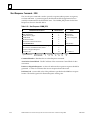
Table 7-2. Retrieve Extended Status Buffer Request COMM_REQ . . . . . . . . . . . . . . . . . . . . . . . . . . . . .
7-2
Table 7-3. Extended Status Buffer Data . . . . . . . . . . . . . . . . . . . . . . . . . . . . . . . . . . . . . . . . . . . . . . . . . . . .
7-2
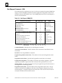
Table 7-4. Retrieve Tallies Request COMM_REQ . . . . . . . . . . . . . . . . . . . . . . . . . . . . . . . . . . . . . . . . . . . .
7-4
Table 7-5. Tallies Structure and Offsets . . . . . . . . . . . . . . . . . . . . . . . . . . . . . . . . . . . . . . . . . . . . . . . . . . . .
7-5
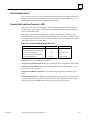
Table 7-6. Retrieve Log Events Request COMM_REQ . . . . . . . . . . . . . . . . . . . . . . . . . . . . . . . . . . . . . . .
7-6
Table 7-7. Event Log Format . . . . . . . . . . . . . . . . . . . . . . . . . . . . . . . . . . . . . . . . . . . . . . . . . . . . . . . . . . . . .
7-6
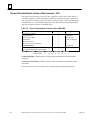
Table 7-8. Restart Ethernet Interface Request COMM_REQ . . . . . . . . . . . . . . . . . . . . . . . . . . . . . . . . . .
7-7
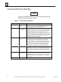
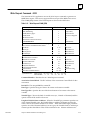
Table 9-1. Ethernet Interface Diagnostic Tools . . . . . . . . . . . . . . . . . . . . . . . . . . . . . . . . . . . . . . . . . . . . . .
9-2
Table 9-2. Power-Up State . . . . . . . . . . . . . . . . . . . . . . . . . . . . . . . . . . . . . . . . . . . . . . . . . . . . . . . . . . . . . . .
9-5
Table 9-3. Soft Switch Entry State . . . . . . . . . . . . . . . . . . . . . . . . . . . . . . . . . . . . . . . . . . . . . . . . . . . . . . . . .
9-6
Table 9-4. Field Network Test State . . . . . . . . . . . . . . . . . . . . . . . . . . . . . . . . . . . . . . . . . . . . . . . . . . . . . . .
9-6
Table 9-5. Loader State . . . . . . . . . . . . . . . . . . . . . . . . . . . . . . . . . . . . . . . . . . . . . . . . . . . . . . . . . . . . . . . . . .
9-7
Table 9-6. Operational State . . . . . . . . . . . . . . . . . . . . . . . . . . . . . . . . . . . . . . . . . . . . . . . . . . . . . . . . . . . . .
9-8
Table 9-7. Troubleshooting with ONLINE LED OFF . . . . . . . . . . . . . . . . . . . . . . . . . . . . . . . . . . . . . . . . .
9-9
Table 9-8. Troubleshooting with ONLINE LED ON . . . . . . . . . . . . . . . . . . . . . . . . . . . . . . . . . . . . . . . . .
9-10
Table 9-9. Exception Log Event Definitions . . . . . . . . . . . . . . . . . . . . . . . . . . . . . . . . . . . . . . . . . . . . . . . . .
9-10
GFK–0868
MMS–Ether net Communications for the Series 90–70 PLC User’s Manual – May
1994
xx
Contents
Table 9-10. Exception Log Event Codes . . . . . . . . . . . . . . . . . . . . . . . . . . . . . . . . . . . . . . . . . . . . . . . . . . .
9-11
Table 9-11. Negative Extended Status Buffer Values . . . . . . . . . . . . . . . . . . . . . . . . . . . . . . . . . . . . . . . . .
9-27
Table 9-12. Extended Status Buffer Error Codes and Definition . . . . . . . . . . . . . . . . . . . . . . . . . . . . . . .
9-27
Table B-1. Protocol Used for GE Fanuc Control Devices . . . . . . . . . . . . . . . . . . . . . . . . . . . . . . . . . . . . . .
B-3
Table B-2. MMS Service Mapping to ACSE and Presentation Services . . . . . . . . . . . . . . . . . . . . . . . . . .
B-4
Table B-3. Effect of VMD Logical State and CNC Mode on MMS Services . . . . . . . . . . . . . . . . . . . . . .
B-16
Table B-4. Domain Attributes . . . . . . . . . . . . . . . . . . . . . . . . . . . . . . . . . . . . . . . . . . . . . . . . . . . . . . . . . . . .
B-18
Table B-5. Domain States . . . . . . . . . . . . . . . . . . . . . . . . . . . . . . . . . . . . . . . . . . . . . . . . . . . . . . . . . . . . . . . .
B-20
Table B-6. Program Invocation Attributes . . . . . . . . . . . . . . . . . . . . . . . . . . . . . . . . . . . . . . . . . . . . . . . . . .
B-21
Table B-7. Program Invocation States . . . . . . . . . . . . . . . . . . . . . . . . . . . . . . . . . . . . . . . . . . . . . . . . . . . . .
B-23
Table B-8. Variable Access Attributes . . . . . . . . . . . . . . . . . . . . . . . . . . . . . . . . . . . . . . . . . . . . . . . . . . . . . .
B-24
Table B-9. GE Fanuc Control Device Data Types . . . . . . . . . . . . . . . . . . . . . . . . . . . . . . . . . . . . . . . . . . . .
B-25
Table B-10. Operator Station Attributes . . . . . . . . . . . . . . . . . . . . . . . . . . . . . . . . . . . . . . . . . . . . . . . . . . . .
B-25
Table B-11. MMS Variable Types and Size . . . . . . . . . . . . . . . . . . . . . . . . . . . . . . . . . . . . . . . . . . . . . . . . . .
B-27
Table C-1. PICS Series 90-70 PLC System ID Information . . . . . . . . . . . . . . . . . . . . . . . . . . . . . . . . . . . .
C-1
Table C-2. PICS Supported Services . . . . . . . . . . . . . . . . . . . . . . . . . . . . . . . . . . . . . . . . . . . . . . . . . . . . . . .
C-2
Table C-3. PICS Supported Parameters . . . . . . . . . . . . . . . . . . . . . . . . . . . . . . . . . . . . . . . . . . . . . . . . . . . .
C-3
Table C-4. PICs Range of Values . . . . . . . . . . . . . . . . . . . . . . . . . . . . . . . . . . . . . . . . . . . . . . . . . . . . . . . . . .
C-3
Table D-1. Pinouts of the Serial Port . . . . . . . . . . . . . . . . . . . . . . . . . . . . . . . . . . . . . . . . . . . . . . . . . . . . . . .
D-2
Table D-2. Pinouts of the AUI Port . . . . . . . . . . . . . . . . . . . . . . . . . . . . . . . . . . . . . . . . . . . . . . . . . . . . . . . .
D-4
Table E-1. Soft Switch Settings . . . . . . . . . . . . . . . . . . . . . . . . . . . . . . . . . . . . . . . . . . . . . . . . . . . . . . . . . . .
E-3
Table F-1. Configuration Parameters via the Station Manager . . . . . . . . . . . . . . . . . . . . . . . . . . . . . . . . .
F-1
Table I-1. MMS–Ethernet Station Configuration Data* . . . . . . . . . . . . . . . . . . . . . . . . . . . . . . . . . . . . . .
I-2
Table I-2. Foreign Device Station Configuration Data . . . . . . . . . . . . . . . . . . . . . . . . . . . . . . . . . . . . . . . .
I-3
GFK–0868
MMS–Ether net Communications for the Series 90–70 PLC User’s Manual – May
1994
xxi
restart lowapp ARestart oddapp: ARestarts for autonumbers that do not restart in
each chapter. figure bi level 1, reset table_big level 1, reset chap_big level 1, reset1
Lowapp Alwbox restart evenap:A1app_big level 1, resetA figure_ap level 1, reset
table_ap level 1, reset figure level 1, reset table level 1, reset these restarts
oddbox reset: 1evenbox reset: 1must be in the header frame of chapter 1. a:ebx, l 1
resetA a:obx:l 1, resetA a:bigbx level 1 resetA a:ftr level 1 resetA c:ebx, l 1 reset1
c:obx:l 1, reset1 c:bigbx level 1 reset1 c:ftr level 1 reset1 Reminders for
autonumbers that need to be restarted manually (first instance will always be 4)
let_in level 1: A. B. C. letter level 1:A.B.C. num level 1: 1. 2. 3. num_in level 1: 1. 2.
3. rom_in level 1: I. II. III. roman level 1: I. II. III. steps level 1: 1. 2. 3.
Chapter
1 Introduction
1
This manual describes the Ethernet Interface and the GEnett System Manager Software
(GSM), which together form a complete Ethernet Communications System for the Series
90–70 PLC. These products are members of the GEnet Factory LAN family of hardware
and software products. The GEnet family of products provides high performance solutions for interconnecting automation controllers and for integrating them into multi–
vendor networks.
This chapter provides an overview of the product and covers the following topics.
H
H
H
The Ethernet Communications System,
How to Make the System Work,
Quick Guide to the Manual.
The Ethernet Communications System
The Figure 1–1 shows the major components of the GEnet Factory LAN, along with a
third– party compatible device, together on one Ethernet cable. Note especially the two
main parts of the Ethernet Communications system, the Ethernet Interface and the GEnet
System Manager Software, and the separation of functions between them.
ÎÎÎ
Transceiver
Ethernet Cable
Network
Connection
Local
RS–232
Connection
ÎÎÎ
ÎÎÎ
ÎÎ
ÎÎ
Î
ÎÎ
Î
Î
Î
ÎÎ
ÎÎ
Î
ÎÎ
Î
Î
ÎÎ
ÎÎ
Î
ÎÎ
Î
Î
Transceiver
Ethernet
Interface
Î
Transceiver
a45339
Series 90–70
PLC
Workmaster or
IBM PC Compatible
Host Computer or
Control Device
GEnet SYSTEM MANAGER Software
GEnet SYSTEM MANAGER
– Creates Configuration Files
for Stations on the Network
– Downloads Configuration
Files and Executive Software
to Interface
– Accesses Station Manager
Software on Interface
– Network and Local Connections
Ethernet Interface
Other Ethernet Devices
– Direct Network Attachment
of PLC
– On–board Diagnostics and
Communication Software
Downloaded from GSM
– GE Fanuc CIMPLICITY
– GE Fanuc CNC
– Third Party Hosts
Figure 1-1. Major Components of the GEnet 802.3 LANN
GFK-0868
1-1
1
The Ethernet Interface allows you to directly attach the Series 90–70 PLC to an Ethernet
LAN via a user–supplied transceiver and AUI cable, and to access hosts and other control devices on the network. Using standard OSI Communications, including MMS
(Manufacturing Message Specification), this interface is compatible with other products
from within GE Fanuc, as well as from other vendors.
The communications services most important to your application are supported, including:
H
H
Data transfer, and
Status indications.
The Ethernet Interface
An operational Ethernet Interface consists of the controller board with resident firmware
and the software downloaded from the GEnet System Manager. The controller board
provides a physical connection from the PLC to the Ethernet LAN. It also is shipped
with on–board diagnostics, a download program to complement the downloader on the
GEnet System Manager, and a utility program that permits testing the cable plant. The
controller board becomes a fully functional communications interface only after downloading additional software from the GEnet System Manager.
Capabilities of the Ethernet Interface
The Ethernet interface brings to your PLC a great deal of capability. It will allow you to:
1-2
H
Directly attach your PLC to a 802.3 CSMA/CD network.
H
Transfer data to and from the PLC from another device. This transfer can occur at
high speeds, and can come from a Host computer, or from other control devices such
as CNCs and other PLCs.
H
Communicate simultaneously to multiple devices. The multiplexing capabilities of
the Ethernet network, along with Ethernet’s high capacity, allow the PLC to hold
communications with several other devices at the same time.
H
Compatibility with other GE Fanuc devices, as well as with devices from other
vendors. The GE Fanuc Series 90–70 PLC is compatible with the CNC Ethernet
Interface and the CIMPLICITYt Host Application. It is also compatible with various
Ethernet products available on DEC, HP, IBM, and other computer platforms.
H
Communicate from a Host computer (or other control device). The host can access
data within the PLC, without specific host knowledge about the PLC‘s internal data
layout. This is accomplished through the data naming that is inherent in MMS.
Data within the PLC can be rearranged without the need for reprogramming the
host.
H
Diagnose and maintain your system, using diagnostic and station management
tools. You can find problems before they become serious, and when
communications software upgrades are desired, you can use your network to
download the software to the interface.
MMS-Ethernet Communications for the Series 90-70 PLC User’s Manual - May 1994
GFK-0868
1
Attachment of the Ethernet Interface to the LAN
The AUI port provides the electrical and mechanical interface to the user–provided
IEEE 802.3 transceiver cable, which connects the AUI port to an external user–provided
transceiver. The external transceiver is directly connected to the Ethernet cable.
Various Ethernet baseband media (10 Base..) can be interconnected by appropriate
repeaters. Capabilities and limitations are defined in IEEE 802.3 Chapter 13, “System
Considerations for Multi-Segment Networks”.
The Ethernet Controller can operate on any of the following media with the appropriate
user–supplied transceiver cable and transceiver. IEEE 802.3 specifies the definitive
requirements of each medium.
10Base5 Coax: 10Base5 uses a 0.4 inch diameter 50-ohm coaxial cable. The maximum
length of a cable segment (single span of cable) is 500 meters. The distance between any
two stations must be a multiple of 2.5 meters. A maximum of 100 stations is allowed on
a thickwire Ethernet segment.
10Base2 Coax: 10Base2 uses a 0.2 inch diameter 50-ohm coaxial cable. The maximum
length of a thinwire cable segment is 185 meters. A maximum of 30 stations is allowed
on a thinwire Ethernet segment.
10BaseT: 10BaseT uses a twisted pair cable of up to 100 meters in length between each
node and a hub or repeater. Typical hubs or repeaters support 6 to 12 nodes connected
in a star wiring topology.
10BaseF: 10BaseF has two variations that both use the same type of fiberoptic cable:
10BaseFP can support up to 33 nodes at distances of up to 500 meters from a passive
star; 10BaseFL supports up to 2000 meters between a node and a repeater (a multi–port
repeater would thus constitute a star). Additionally, 10BaseFB provides a means of
interconnecting (only) repeaters by up to 2000 meters of (the same) fiber optic cable.
10Broad36: 10Broad36 uses 75–ohm coaxial cable and CATV–lik e media components
(taps, amplifiers, headend translators, etc.) to support hundreds of nodes at distances of
up to 2800 meters. Broadband cannot be connected to baseband via repeaters.
Broadband cable plant design and installation must be in accordance with IEEE 802.7
and requires special expertise. GE Fanuc recommends you contract professional
specialists for these services. Consult your GE Fanuc sales representative or field service
office for help in identifying local specialists.
The Ethernet Software
As stated above, the Ethernet Interface becomes fully functional only after additional software is downloaded from the GEnet System Manager. The downloaded software consists
of:
The Station Manager. The Station Manager provides On–Line supervisory access to the
Interface, through either the serial port on the controller board or over the Ethernet
cable. These Station Manager services on the Ethernet Interface include:
GFK0868
H
H
An interactive set of commands for interrogating and controlling the station.
H
Password security for commands that change station parameters or operation.
Unrestricted access to observe internal statistics, an exception log, and configuration
parameters.
Chapter 1 Introduction
1-3
1
Communications Software. This software consists of the 7–layer ISO protocol stack and
interface software interfacing the protocol stack with the PLC.
Configuration File. This configuration data consists largely of timing, buffer, addressing, and other parameters for each station on the network.
The GEnet System Manager (GSM)
The GEnet System Manager is a menu–driven software package that runs on a user–provided IBM PC or equivalent running DOS 5.0. The GSM provides various management
and configuration tools. The GSM can be connected to the Ethernet Interface either with a
serial RS–232 cable, or over the Ethernet cable. When used over Ethernet, one GSM can
conveniently access any of the Ethernet Interfaces on that cable.
The most essential GSM tools are:
H
H
H
The Configuration Editor
The Downloader
Access to the Station Manager on the Ethernet Interface
In addition, the GSM has the following functions:
H
H
H
Examine the list of configured Ethernet Interfaces.
Examine and modify network–wide configuration parameters.
Create and examine the application Directory Information Bases (DIBs). The GSM
also can create files containing these DIBs.
Note
Typically, there will be only one GSM on the network. It will contain
configuration information and communications software for all the
GEnet stations on the network.
The Configuration Editor
The Configuration Editor is a menu–driven software package that is part of the GSM. It is
used offline to examine and modify configuration parameters for all the GEnet Ethernet Interfaces on your network. These configuration parameters are stored in files on the PC hard
disk and subsequently downloaded to the interface using the GSM Downloader.
The Downloader
The Downloader is a utility which transfers the Communications Software and the Configuration File to the Ethernet Interface. The Downloader operates in two modes,
local (RS232) and network. The Downloader and the download mode are selected in the
main screen of the GSM.
Access to the Station Manager on the Ethernet Interface
The Ethernet Interface provides an interactive maintenance interface called the Station
Manager (described in Chapter 4). The Station Manager allows you to view current and
historical information about the operation of the Ethernet Interface. The GSM provides
access to the Ethernet Interface and Station Manager in both local and network modes.
1-4
MMS-Ethernet Communications for the Series 90-70 PLC User’s Manual - May 1994
GFK-0868
1
Access to the Station Manager and the access mode are selected in the main screen of the
GSM.
How to Make it Work
There are a number of tasks required to get your Ethernet Communications System
working. These tasks involve not only the Ethernet Interface and the GEnet System Manager Software, but also Logicmaster Configuration and depending on your applications, Programming Software. The figure below illustrates what the tasks are for each part of the system.
User supplied
IBM PC
Compatible
Î
Î
GSM Software
Install GSM Software
Î
Î
a45340
Î
Î
ÎÎ
Î
ÎÎ
Î
ÎÎ
Î
ÎÎ
ÎÎÎ
Î
ÎÎ
Î
ÎÎ
Î
ÎÎ
Î
ÎÎ
Î
ÎÎ
Î
Î
ÎÎ
Î
ÎÎ
ÎÎ
Î
ÎÎ
Î
ÎÎ
ÎÎÎ
ÎÎ
ÎÎ
ÎÎ
ÎÎÎ
ÎÎ
Î
Series 90–70 PLC
Ethernet Interface
Logicmaster Software
Install Logicmaster
Software
Install Interface in PLC
Power–Up PLC
Use Configuration
Editor to Create
Configuration
Files for Stations
Access
Station Manager
to Run
Field Network Test
Use LM90
Configuration
Package to Perform
ModuleConfiguration
Use
Downloader to
Download
Configuration
Files and Executive
Software to Interface
Access
Station Manager on
Interface to Monitor
and ManageNetwork
* Needed only if 90-70 PLC
will initiate communications.
Fully
Operational
Station
Use LM90 *
Programming Package
to Perform
COMMunications
REQuest
Figure 1-2. The Main Tasks for Installing the Ethernet
Communications System
GFK0868
Chapter 1 Introduction
1-5
1
Quick Guide to the Manual
As you can see from Figure 1–2, the tasks to install the Ethernet Communications System
take three paths.
1.
GEnet System Manager (GSM) Tasks
2.
Logicmaster Configuration and Programming Tasks
3.
Ethernet Interface Tasks
The table below breaks down these tasks and identifies where in the manual they are
described.
ÁÁÁÁÁÁÁÁÁÁÁÁ
ÁÁÁÁÁÁÁÁÁÁÁÁÁÁÁÁÁ
ÁÁÁÁÁÁÁÁÁÁÁÁ
ÁÁÁÁÁÁÁÁÁÁÁÁÁÁÁÁÁ
ÁÁÁÁÁÁÁÁÁÁÁÁ
ÁÁÁÁÁÁÁÁÁÁÁÁÁÁÁÁÁ
ÁÁÁÁÁÁÁÁÁÁÁÁ
ÁÁÁÁÁÁÁÁÁÁÁÁÁÁÁÁÁ
ÁÁÁÁÁÁÁÁÁÁÁÁ
ÁÁÁÁÁÁÁÁÁÁÁÁÁÁÁÁÁ
ÁÁÁÁÁÁÁÁÁÁÁÁ
ÁÁÁÁÁÁÁÁÁÁÁÁÁÁÁÁÁ
ÁÁÁÁÁÁÁÁÁÁÁÁ
ÁÁÁÁÁÁÁÁÁÁÁÁÁÁÁÁÁ
ÁÁÁÁÁÁÁÁÁÁÁÁ
ÁÁÁÁÁÁÁÁÁÁÁÁÁÁÁÁÁ
ÁÁÁÁÁÁÁÁÁÁÁÁ
ÁÁÁÁÁÁÁÁÁÁÁÁÁÁÁÁÁ
ÁÁÁÁÁÁÁÁÁÁÁÁ
ÁÁÁÁÁÁÁÁÁÁÁÁÁÁÁÁÁ
ÁÁÁÁÁÁÁÁÁÁÁÁ
ÁÁÁÁÁÁÁÁÁÁÁÁÁÁÁÁÁ
ÁÁÁÁÁÁÁÁÁÁÁÁ
ÁÁÁÁÁÁÁÁÁÁÁÁÁÁÁÁÁ
ÁÁÁÁÁÁÁÁÁÁÁÁ
ÁÁÁÁÁÁÁÁÁÁÁÁÁÁÁÁÁ
ÁÁÁÁÁÁÁÁÁÁÁÁ
ÁÁÁÁÁÁÁÁÁÁÁÁÁÁÁÁÁ
ÁÁÁÁÁÁÁÁÁÁÁÁ
ÁÁÁÁÁÁÁÁÁÁÁÁÁÁÁÁÁ
ÁÁÁÁÁÁÁÁÁÁÁÁ
ÁÁÁÁÁÁÁÁÁÁÁÁÁÁÁÁÁ
ÁÁÁÁÁÁÁÁÁÁÁÁ
ÁÁÁÁÁÁÁÁÁÁÁÁÁÁÁÁÁ
ÁÁÁÁÁÁÁÁÁÁÁÁ
ÁÁÁÁÁÁÁÁÁÁÁÁÁÁÁÁÁ
ÁÁÁÁÁÁÁÁÁÁÁÁ
ÁÁÁÁÁÁÁÁÁÁÁÁÁÁÁÁÁ
ÁÁÁÁÁÁÁÁÁÁÁÁ
ÁÁÁÁÁÁÁÁÁÁÁÁÁÁÁÁÁ
ÁÁÁÁÁÁÁÁÁÁÁÁ
ÁÁÁÁÁÁÁÁÁÁÁÁÁÁÁÁÁ
ÁÁÁÁÁÁÁÁÁÁÁÁ
ÁÁÁÁÁÁÁÁÁÁÁÁÁÁÁÁÁ
ÁÁÁÁÁÁÁÁÁÁÁÁ
ÁÁÁÁÁÁÁÁÁÁÁÁÁÁÁÁÁ
ÁÁÁÁÁÁÁÁÁÁÁÁ
ÁÁÁÁÁÁÁÁÁÁÁÁÁÁÁÁÁ
ÁÁÁÁÁÁÁÁÁÁÁÁ
ÁÁÁÁÁÁÁÁÁÁÁÁÁÁÁÁÁ
ÁÁÁÁÁÁÁÁÁÁÁÁ
ÁÁÁÁÁÁÁÁÁÁÁÁÁÁÁÁÁ
ÁÁÁÁÁÁÁÁÁÁÁÁ
ÁÁÁÁÁÁÁÁÁÁÁÁÁÁÁÁÁ
ÁÁÁÁÁÁÁÁÁÁÁÁ
ÁÁÁÁÁÁÁÁÁÁÁÁÁÁÁÁÁ
ÁÁÁÁÁÁÁÁÁÁÁÁ
ÁÁÁÁÁÁÁÁÁÁÁÁÁÁÁÁÁ
ÁÁÁÁÁÁÁÁÁÁÁÁ
ÁÁÁÁÁÁÁÁÁÁÁÁÁÁÁÁÁ
ÁÁÁÁÁÁÁÁÁÁÁÁ
ÁÁÁÁÁÁÁÁÁÁÁÁÁÁÁÁÁ
Tasks
GEnet System Manager (GSM)
Installing, Starting Up, and
Using the GSM
Where to go in the Manual
Chapter 3.
Chapter 4.
The GEnet System Manager
Section 1.
Installing and
Starting–Up the GSM
Appendix H Sample DOS system files
The GEnet System Manager
Section 2.
Configuring Stations for
a Basic Network
ISO Networking Concepts
ISO Networking Concepts
Tuning and Configuring Stations for
an Advanced Network
The GEnet System Manager
Section 3.
Downloading a Station
The GEnet System Manager
Section 4.
Accessing the Station Manager
The Station Manager
Chapter 5.
Chapter 6.
Procedure 7. Using the Example PLC
Ladder Program
General PLC Application Programming
OSI COMMunication REQuest
Chapter 7.
Station Manager COMMunication REQuest
Chapter 2.
Chapter 4.
Installing the Ethernet Interface
Procedure 1. Installing the Interface
Procedure 2. Verifying Proper Power–
Up of the Interface
Procedure 3. Configuring the Interface
with the Logicmaster 90–70
Configurator
Procedure 5. Testing the Interface on
the Network
The Station Manager
Chapter 9.
Troubleshooting
Configuring Stations for a Basic
Network
Chapter 3.
ISO Parameters (General Info.)
MMS Parameters
Configuring Stations for an
Advanced Network
Downloading a Station
Appendix B.
Appendix B.
Chapter 8.
Accessing the Station Manager
(Terminal Emulation Mode)
Chapter 3.
Logicmaster Programming
Using the Example PLC Ladder
Program
Programming COMMunications
REQuests
Ethernet Interface
Installing the Interface
Chapter 3.
Powering–Up the Interface
Configuring the Module
(Setting Soft Switch Configuration)
Field Network Tests
Monitoring the Station and
Managing the Network
Troubleshooting the Interface on
the Network
1-6
MMS-Ethernet Communications for the Series 90-70 PLC User’s Manual - May 1994
GFK-0868
Chapter
2 Installing the Ethernet Interface
2
section level 1 1
figure bi level 1
table_big level 1
This chapter describes the basic features of the Ethernet Interface, the installation of the
interface, and a procedure for the initial checkout of the interface on your Ethernet
cable. The chapter first provides a hardware overview of the Ethernet Interface. It is
then divided into six Installation Procedures, each providing an overview of the procedure, explaining the steps to be performed, and describing the expected results.
As you work through a procedure you may encounter references to the appendices and
other chapters in this manual. These references provide more detailed information
about the subject under discussion.
The installation procedures described in this chapter are listed below:
H
H
H
Procedure 1: Installing the Interface in the PLC Rack - Required
H
H
H
Procedure 4: Configuring and Downloading a Station - Required
Procedure 2: Verifying Proper Power-Up of the Interface - Required
Procedure 3: Configuring the Interface with the Logicmastert 90-70 Configurator Required
Procedure 5: Testing the Interfaces on the Network - Optional
Procedure 6: Using the Example PLC Ladder Program - Optional
Some of the procedures require prior cable plant design and installation.
After completing the Installation Procedures you will gain an understanding of the parts
of the network and how they fit together. You will also have confidence that your equipment is working properly.
GFK-0868
2-1
2
Ethernet Hardware Overview
The Ethernet Interface consists of a controller board mounted in the Series 90-70 PLC
rack. It is connected to an external transceiver via a user-provided transceiver cable. The
external transceiver is then connected to the Ethernet cable. The figure below shows the
layout of the Ethernet Controller board.
LEDS
RESTART
PUSHBUTTON
OPEN
REPLACEMENT
BATTERY
CONNECTOR
ÎÎ
ÎÎ
ÎÎ
ÎÎ
Î
ÎÎÎÎ
ÎÎ
Î
ÎÎ
ÎÎ
Î
ÎÎ
ÎÎ
Î
Î
ÎÎ
ÎÎ
Î
Î
ÎÎ
Î
Î
ÎÎ
Î
ÎÎ
Î
ÎÎ
Î
ÎÎ
Î
ÎÎ
Î
ÎÎ
Î
ÎÎ
Î Î
ÎÎ
Î
Î
ÎÎ
Î
ÎÎ
Î
Î
Î
ÎÎ
Î
ÎÎ
Î
Î
ÎÎ
Î
Î
Î
Î Î
ÎÎ
Î
ÎÎ Î Î
B
A
T
T
E
R
Y
a44663
Î
MODEL 70
CMM 741
MODULE OK
ONLINE
STATUS OK
CURRENTLY
ON OR BLINK= OK
INSTALLED
PUSH TO RESTART
BATTERY
LAN INTERFACE.
CONNECTOR
PUSH AND HOLD
Î
TOREQUEST
LAN INTERFACE
DOWNLOAD.
INOP
WHEN RUNNING
9–PIN
SERIAL
DIAGNOSTICS
PORT
BATTERY
CONNECTIONS
INSTALL NEW
BATTERY BEFORE
15–PIN
UNPLUGGING OLD
ETHERNET
BATTERY. USE
CONNECTOR
IC697ACC701
SERIAL
PORT
RS–232
DTE
2 TX (OUT)
3 RX (IN)
7 GND
DEFAULT
STATION
ADDRESS
LABEL
PUSH
SLIDEFROM
FRONTTO
LOCK:FROM
BACK TO
RELEASE
TRANSCEIVER
CABLE
MODULE
Î Î
ÎÎ
ÎÎ
IC697CCM741
LABEL
44A726758–117R01
GROUND
WIRE
ÎÎ
SERIAL
NUMBER
LABEL
Figure 2-1. Ethernet Controller Board
The Ethernet Controller board has several user-accessible elements.
Three LEDs are located at the top of the board. The Restart pushbutton is located immediately below the LEDs. The battery and battery holder is located to the right of the
LEDs. The battery connectors are located on the controller board between the Restart
button and the 9-pin connector to the serial port. The 15-pin connector, located beneath
the serial port and facing downward, is the transceiver port. The Default Station Address label is affixed on the outside of the plastic housing.
2-2
MMS-Ethernet Communications for the Series 90-70 PLC User’s Manual - May 1994
GFK-0868
2
Board Indicators
There are three LEDs on the Ethernet Controller board. The table below describes the
general meaning of each of the LEDs..
ÁÁÁÁÁÁ
ÁÁÁÁÁÁ
ÁÁÁÁÁÁÁÁÁÁÁÁÁÁÁ
ÁÁÁÁÁÁ
ÁÁÁÁÁÁ
ÁÁÁÁÁÁÁÁÁÁÁÁÁÁÁ
ÁÁÁÁÁÁ
ÁÁÁÁÁÁ
ÁÁÁÁÁÁÁÁÁÁÁÁÁÁÁ
ÁÁÁÁÁÁ
ÁÁÁÁÁÁ
ÁÁÁÁÁÁÁÁÁÁÁÁÁÁÁ
ÁÁÁÁÁÁ
ÁÁÁÁÁÁ
ÁÁÁÁÁÁÁÁÁÁÁÁÁÁÁ
ÁÁÁÁÁÁ
ÁÁÁÁÁÁ
ÁÁÁÁÁÁÁÁÁÁÁÁÁÁÁ
ÁÁÁÁÁÁ
ÁÁÁÁÁÁ
ÁÁÁÁÁÁÁÁÁÁÁÁÁÁÁ
ÁÁÁÁÁÁ
ÁÁÁÁÁÁ
ÁÁÁÁÁÁÁÁÁÁÁÁÁÁÁ
ÁÁÁÁÁÁ
ÁÁÁÁÁÁÁÁÁÁÁÁÁÁÁ
ÁÁÁÁÁÁ
ÁÁÁÁÁÁ
ÁÁÁÁÁÁ
ÁÁÁÁÁÁÁÁÁÁÁÁÁÁÁ
ÁÁÁÁÁÁ
ÁÁÁÁÁÁ
ÁÁÁÁÁÁÁÁÁÁÁÁÁÁÁ
H
ÁÁÁÁÁÁ
ÁÁÁÁÁÁ
ÁÁÁÁÁÁÁÁÁÁÁÁÁÁÁ
ÁÁÁÁÁÁ
ÁÁÁÁÁÁ
ÁÁÁÁÁÁÁÁÁÁÁÁÁÁÁ
H
H
ÁÁÁÁÁÁ
ÁÁÁÁÁÁ
ÁÁÁÁÁÁÁÁÁÁÁÁÁÁÁ
ÁÁÁÁÁÁ
ÁÁÁÁÁÁ
ÁÁÁÁÁÁÁÁÁÁÁÁÁÁÁ
ÁÁÁÁÁÁ
ÁÁÁÁÁÁ
ÁÁÁÁÁÁÁÁÁÁÁÁÁÁÁ
ÁÁÁÁÁÁ
ÁÁÁÁÁÁ
ÁÁÁÁÁÁÁÁÁÁÁÁÁÁÁ
ÁÁÁÁÁÁ
ÁÁÁÁÁÁ
ÁÁÁÁÁÁÁÁÁÁÁÁÁÁÁ
ÁÁÁÁÁÁ
ÁÁÁÁÁÁ
ÁÁÁÁÁÁÁÁÁÁÁÁÁÁÁ
ÁÁÁÁÁÁ
ÁÁÁÁÁÁ
ÁÁÁÁÁÁÁÁÁÁÁÁÁÁÁ
ÁÁÁÁÁÁ
ÁÁÁÁÁÁ
ÁÁÁÁÁÁÁÁÁÁÁÁÁÁÁ
ÁÁÁÁÁÁ
ÁÁÁÁÁÁ
ÁÁÁÁÁÁÁÁÁÁÁÁÁÁÁ
ÁÁÁÁÁÁ
ÁÁÁÁÁÁÁÁÁÁÁÁÁÁÁ
ÁÁÁÁÁÁ
ÁÁÁÁÁÁ
ÁÁÁÁÁÁ
ÁÁÁÁÁÁÁÁÁÁÁÁÁÁÁ
ÁÁÁÁÁÁ
ÁÁÁÁÁÁ
ÁÁÁÁÁÁÁÁÁÁÁÁÁÁÁ
ÁÁÁÁÁÁÁÁÁÁÁÁÁÁÁÁÁÁÁÁÁ
Restart Button ÁÁÁÁÁÁ
Table 2-1. Ethernet Controller Board Indicators
Indicator
MODULE OK
Status
ON
OFF
BLINKING
ONLINE
ON
OFF
BLINKING
STATUS OK
Description
MODULE OK is ON if the Ethernet Interface has
passed diagnostics and its hardware is operating
properly.
It is OFF if the module fails a diagnostic test or if a
fatal failure is detected while the board is running.
This LED is blinking if the module is running diagnostics or is in Soft Switch entry state.
If this LED and the STATUS OK LED are blinking together, diagnostics have completed and the operator is
being given a chance to enter Field Network Test.
ONLINE is ON when the Ethernet Interface is connected to and ready to communicate on the network.
This LED is OFF when:
the station is not communicating on the network
due to disconnection or a disruption of the cable.
the local station has malfunctioned or
the Ethernet Interface has been commanded not
to enter the network or is in a state where
network operation is inappropriate, such as Soft
Switch Entry state or local loading.
It is BLINKING when the module is transferring data
on the network or loading over the network.
ON
STATUS OK is ON if the module is running without
exceptionconditions.
OFF
This LED is OFF if the module is running and detects
an event that calls for supervisory attention. In this
case you should connect the GSM and follow the
instructions in Chapter 9 to obtain further
information.
This LED is BLINKING if the module is loading or
looking for a load source for the Ethernet Interface
software.
BLINKING
The Restart button serves two functions: Restart, and Restart and Reload. The Restart
button is inaccessible when the door to the Ethernet Interface is closed.
Restart: Pressing the Restart button (for fewer than 5 seconds) forces a restart of the
Ethernet Interface. The power-up diagnostics run and the software on the module is
restarted when the pushbutton is released.
Restart and Reload: Pressing and holding the Restart button for 5 seconds or more
forces a restart and requests a reload of the Ethernet Interface. When the Restart button
is pressed, all LEDs go out. After 5 seconds have elapsed, the STATUS OK LED comes
ON, to indicate that the Ethernet Interface will request a reload. After the Restart pushbutton is released, the power-up diagnostics run and the Ethernet Interface requests to
be loaded.
GFK-0868
Chapter 2 Installing the Ethernet Interface
2-3
2
Notes
In either case, any data being transferred by the Ethernet Interface at
the time of the Restart will be lost.
The Restart Pushbutton will not be operable during the Ethernet
Controller board diagnostic phase. The Ethernet Controller board is in
diagnostic phase when the BOARD OK LED is BLINKING and the
ONLINE and STATUS OK LEDs are off.
Battery
When connected, the battery preserves the contents of RAM when there is no power to
the board. The battery will maintain RAM contents for a minimum of six months.
Warning
The lithium battery presents a fire, explosion, or severe burn risk. Do
NOT: recharge it, remove its polarized connector, disassemble it, heat
it above 100C (212F), incinerate it, or expose its cell contents to water.
Dispose of the battery as required by applicable ordinances or
regulations. When replacing the battery, use only Catalog No.
IC697ACC701. Use of another battery could result in ignition or
explosion of the battery. Replacement batteries can be ordered from
GE Fanuc Automation - NA or any GE Fanuc Authorized Distributor.
Serial Port
The 9-pin serial port (RS-232 interface) is used to connect to the GEnet System Manager
(GSM). The communication software on the distribution diskette may be loaded
through this port. A cable is needed to connect the GSM to the Ethernet Interface (see
Appendix D, Communications Ports Characteristics). The faceplate of the Interface must
be open to connect the cable. The serial port may also be used with a serial terminal for
local Station Management.
AUI (Transceiver) Port
The 15-pin AUI port provides the electrical and mechanical interface to the user-provided IEEE 802.3 transceiver cable, which connects the AUI Port to an external IEEE
802.3-compatible transceiver (see Appendix D for the characteristics of the AUI Port).
The external transceiver is directly connected to the Ethernet cable.
Default Station Address Label
The Default Station Address label lists the default station address to be used by this module, unless changed by the user.
Serial Number Label
The Serial Number Label indicates the serial number of this controller board.
2-4
MMS-Ethernet Communications for the Series 90-70 PLC User’s Manual - May 1994
GFK-0868
2
Procedure 1: Installing the Ethernet Interface in the PLC
This section describes the physical installation of the Ethernet Controller board into the
Series 90-70 PLC rack. For information on the installation procedures for the rack, 90-70
CPU, Power Supply, and other Series 90-70 modules, refer to GFK-0262, Series 90-70 Programmable Controller Installation and Operation User’s Manual.
Equipment Required to Perform the Installation Procedures
In addition to the Ethernet Controller board, make sure you have the items listed below
before you begin.
H
H
H
H
H
H
A Series 90-70 PLC rack.
H
H
A certified IEEE 802.3-compatible transceiver and Ethernet cables.
A Series 90-70 CPU.
An operating Logicmastert 90-70 system (serial, parallel, or network version).
A Workmaster, or IBM-compatible personal computer.
The GEnet Ethernet Interface software diskette.
A copy of the data sheet applicable to your Ethernet Controller board and cable
plant.
A serial cable for the RS-232 connector on the Ethernet Controller board (see
Appendix D).
Note
The Ethernet Interface requires a power supply that can provide +5 Vdc
and +12 Vdc. Use one of the following power supplies:
IC697PWR711
IC697PWR721
IC697PWR731
Ethernet Interface Installation
The Series 90-70 PLC Ethernet Interface installation is summarized here.
GFK-0868
1.
Read and record the 12-digit default station address (MAC address) from the printed
label on the Ethernet Controller board. A Station Configuration Data Form is
provided in Appendix I for your convenience in recording the station configuration
information.
2.
Be sure the Series 90-70 PLC rack power is OFF.
3.
Connect the battery to either of the battery connectors on the controller board.
4.
Slide the Ethernet Controller into the Series 90-70 PLC slot for which it was
configured in the system - normally the first available slot to the right of the CPU,
Bus Transmitter Module (BTM), or Bus Receiver Module (BRM).
Chapter 2 Installing the Ethernet Interface
2-5
2
Press firmly to lock the board in place, but do not force the board. (See Figure 2-2 for
PLC rack, and Figure 2-3 for expansion rack layout.)
Note
The Ethernet Controller board will not operate properly if there are
empty slots to the left of the slot you select.
5.
Connect the free end of the safety wire (18 inch long green wire attached to the
Ethernet Controller board) to the ground lug at the side of the Series 90-70 PLC rack.
(See Figure 2-2).
Warning
The ground wire must be securely fastened to the chassis of the Series
90-70 PLC rack and the rack must be properly grounded. Failure to do
so may cause personal injury.
6.
Connect the transceiver cable into the 15-pin AUI Port of the Ethernet Controller
board. Secure the cable with the slide latch mechanism. The other end of the
transceiver cable should be connected to an external IEEE 802.3 compatible
transceiver which is attached to the Ethernet network. SQE must be enabled on the
transceiver.
7.
Set the CPU Run/Stop switch to STOP.
8.
Continue with Procedure 2: Verifying Ethernet Interface Power-Up.
Ethernet Interface Installed in Series 90-70 PLC Rack
a45344
Î
P
S
C
P
U
GROUND WIRE
B
T
M
E
T
H
E
R
N
E
T
Î
TRANSCEIVER
CABLE
TO
802.3
TRANSCEIVER
Figure 2-2. Ethernet Controller Installation in the Series 90-70 PLC
2-6
MMS-Ethernet Communications for the Series 90-70 PLC User’s Manual - May 1994
GFK-0868
2
Ethernet Interface Installed in Expansion Racks
Installation of the Ethernet Interface in the expansion racks is shown in Figure 2-3. Expansion racks are connected to the CPU through an 18 twisted-pair cable (called the I/O
cable) with one end connected to the lower connector on a Bus Transmitter Module
installed in the CPU rack in slot 2, and the other end connected to the top connector on a
Bus Receiver Module (BRM) installed in slot 1 in an expansion rack. Each additional rack
is then connected in a daisy chain through I/O cables connected to the top and bottom
connectors on the BRMs.
The total cable length from the CPU rack to the last expansion rack may be a maximum
of 50 feet (15 meters). I/O cables are available in various lengths from 2 to 50 feet (0.6 to
15 meters). Additionally, a single power supply can power two racks (within current
limits) when connected by an available cable three feet (1 meter) in length.
The I/O bus in an expanded system must be terminated by installing an I/O bus Terminator plug on the bottom connector of the BRM. This Terminator plug contains a resistor
pack configured for proper I/O bus termination. If there are more than two racks in an
expansion system, the intermediate expansion racks must not have the Terminator plug
installed.
Note
Install no more than four (4) LAN Interfaces in a single Series 90-70 PLC
system.
RACK 0
Î
P
S
Î
P
S
Î
C B
P T
U M
ONE
METER
a44725
RACK 1
Î
B L
R A
M N
TRANSCEIVER CABLE
GROUND
WIRE
RACK 6
Î
P
S
Î
NOTE
12V POWER SUPPLY
NEEDED IN RACK
THAT ETHERNET
CONTROLLER
BOARD IS IN.
TO
802.3
TRANSCEIVER
Î
B
R
M
ONE
METER
P
S
NOTE
TOTAL LENGTH OF ALL
INTERCONNECTING
CABLES FROM BTM TO
LAST BRM IS
50 FEET(MAXIMUM).
ALL RACKS MUST BE AT
SAME GROUND POTENTIAL
(8 RACKS MAXIMUM).
RACK 7
Î
B
R
M
I/O TERMINATOR
(LAST RACK)
LEGEND
CPU
BRM
BTM
PS
LAN
–
–
–
–
–
SERIES 90–70 CPU
BUS RECEIVER MODEL, BEM711
BUS TRANSMITTER MODEL, BEM 713
POWER SUPPLY
ETHERNET CONTROLLER, CMM741
Figure 2-3. Ethernet Interface Installation in an Expansion Rack
GFK-0868
Chapter 2 Installing the Ethernet Interface
2-7
2
Procedure 2: Verifying Proper Power-Up of the Interface
Before powering–up the Ethernet Interface, you may wish to connect the GEnet System
Manager (GSM) locally to the Interface, and select the “Station Manager” function from
the GSM Main menu. This allows you to observe the progress of the power–up diagnostics via the Station Manager software on the Interface. The GSM is also used to perform
other operations in subsequent Installation Procedures.
Refer to Chapter 3, “The GEnet System Manager”, for instructions on installing the GSM
software on a user-suppliedPC-compatiblecomputer.
Note
Alternatively, you can use a dumb terminal, or another terminal
emulation product on a PC. However, you will probably find it most
convenient to use the GSM since you will be using the GSM for other
configuration purposes in subsequent steps.
If you do not use the GSM, configure the terminal for 9600 bps, 8 bits,
no parity, and 1 stop bit. See Appendix D, for instructions on making
the serial cable.
Using the GSM “Access Station Manager” Function
The Station Manager software on the Ethernet Interface is accessed by connecting the
LAN Interface to a personal computer running the GSM software and selecting the “Station Manager” function from the GSM main menu.
1.
There are two ways the GSM can be physically connected to an Interface: Local
Connection and Network Connection.
Note
To observe the progress of Power–Up Diagnostics described in this
procedure and to invoke the Field Network Test Utility described in
Installation Procedure 5, the GSM must be connected locally and put in
the Local Station Manager Communications Mode.
A. GSM Using Local Connection. Connect the COM1 RS–232 serial port on the
device running the GSM to the 9–pin connector on the Ethernet Interface. Refer
to Appendix D for instructions on how to make the RS–232 cable.
B. GSM Using Network Connection. Connect the Ethernet Interface on the
device running the GSM to the Ethernet Network.
For now, use the Local connection.
2.
2-8
Power–up the computer running the GSM into DOS.
MMS-Ethernet Communications for the Series 90-70 PLC User’s Manual - May 1994
GFK-0868
2
3.
Set the PC default directory to the GSM directory, by typing:
C:\> cd \gsm
4.
Start–up the GSM by typing:
C:\GSM> gsm
5.
At the password screen, type in the password. The default password is “gsm”
6.
Once the GSM Main Menu appears, go into the Setup GSM functions to set the
Station Manager Communications Mode to Local, exiting with <ALT-U>.
7.
From the GSM Main Menu, cursor to the “Station Manager” function and press
Enter to select.
If you selected Local Communications Mode in step 6, the GSM will automatically
access the Station Manager of the locally connected Ethernet Interface. If you are
prompted for “Station Name”, you did not select Local Station Manager mode.
Repeat step 6.
States of the Ethernet Interface
The figure below shows the 5 possible states of the Ethernet Interface. The states are
distinguished by LED patterns and by unique Station Manager NODE command and
prompt outputs.
ÎÎÎÎÎ
ÎÎÎÎÎ
ÎÎÎÎÎ ÎÎÎÎ
ÎÎÎÎ
ÎÎÎÎ
ÎÎÎÎÎÎ
ÎÎÎÎÎÎ
ÎÎÎÎÎÎÎÎÎÎ
ÎÎÎÎ
ÎÎÎÎ
ÎÎÎÎÎ
ÎÎÎÎÎ
a45163
Power Up/
Restart
Certain
Exceptions
Detected
Pass
Soft
Switches
OK?
No
<Restart>
Soft Switch
Entry Utility
Yes
Issue ”@”
Station Manager Prompt
Receive
”F”
Response?
Yes
<Restart>
Field Network
Test Utility
No
<Done>
Loader
Utility
No
RAM
Software
Loaded/Checksum
Correct?
Yes
ÎÎÎÎÎ
ÎÎÎÎÎ
Operational
The operations above the
line are executed from PROM
The operations below the
line are executed from the
Configuration and
Communications Software
downloaded by the user.
Figure 2-4. States of the Ethernet Interface
GFK-0868
Chapter 2 Installing the Ethernet Interface
2-9
2
The Ethernet Interface will normally transition from the Power–Up State to the Operational State without entering any other state.
If there is a problem with the Soft Switch data, however, the Ethernet Interface will transition automatically to the Soft Switch Entry State (see Appendix E for instructions).
And if you have not previously downloaded a station configuration to the Interface, the
Interface will transition automatically to the Loader Utility (see Procedures 5 and 6 for
instructions). Also, the operator may manually cause the Interface to enter the Field
Network Test Utility.
Powering–Up the Interface
Follow the procedure below to verify that the Interface is operating correctly.
1.
Power–up the PLC. This will initiate a series of diagnostic tests.
Upon power–up the Module OK LED blinks, On Line and Status OK LEDs are OFF.
2.
Observe the local Station Manager screen if connected. If power–up is successful,
then a Station Manager message similar to the following will be displayed, normally
within 15 seconds.
IC697 PLC Factory LAN Interface
Copyright (c) 1990-1994. All rights reserved.
PROM version 1.14, Software version 1.13 MMS/Ethernet
MAC address = <<080019010177>>
Serial no. 01913826, MAC default = <<080019010177>>
3.
Also, the LEDs will have the following pattern upon successful power up. At this
time the Interface is in the Operational State.
ÁÁÁÁÁÁ
ÁÁÁÁÁÁÁÁ
ÁÁÁÁÁÁ
ÁÁÁÁÁÁÁÁ
ÁÁÁÁÁÁ
ÁÁÁÁÁÁÁÁ
ÁÁÁÁÁÁ
ÁÁÁÁÁÁÁÁ
ÁÁÁÁÁÁ
ÁÁÁÁÁÁÁÁ
LED
Module OK
On Line
Status OK
2-10
Interface On Line
ON
ON
ON
MMS-Ethernet Communications for the Series 90-70 PLC User’s Manual - May 1994
GFK-0868
2
Problems During Power–Up
The Interface may not transition directly to the Operational State upon power–up or
restart. It may stop in another state or a fault may have been detected. Refer to the
table below for possible states your Ethernet Interface can assume after completion of
power-up diagnostics.
ÁÁÁÁÁÁÁ
ÁÁÁÁÁÁÁ
ÁÁÁÁÁÁÁÁÁÁ
ÁÁÁÁÁÁÁÁÁÁÁ
ÁÁÁÁÁÁÁ
ÁÁÁÁÁÁÁ
ÁÁÁÁÁÁÁÁÁÁ
ÁÁÁÁÁÁÁÁÁÁÁ
ÁÁÁÁÁÁÁ
ÁÁÁÁÁÁÁ
ÁÁÁÁÁÁÁÁÁÁ
ÁÁÁÁÁÁÁÁÁÁÁ
ÁÁÁÁÁÁÁ
ÁÁÁÁÁÁÁ
ÁÁÁÁÁÁÁÁÁÁ
ÁÁÁÁÁÁÁÁÁÁÁ
ÁÁÁÁÁÁÁ
ÁÁÁÁÁÁÁ
ÁÁÁÁÁÁÁÁÁÁ
ÁÁÁÁÁÁÁÁÁÁÁ
ÁÁÁÁÁÁÁ
ÁÁÁÁÁÁÁ
ÁÁÁÁÁÁÁÁÁÁ
ÁÁÁÁÁÁÁÁÁÁÁ
ÁÁÁÁÁÁÁ
ÁÁÁÁÁÁÁ
ÁÁÁÁÁÁÁÁÁÁ
ÁÁÁÁÁÁÁÁÁÁÁ
ÁÁÁÁÁÁÁ
ÁÁÁÁÁÁÁ
ÁÁÁÁÁÁÁÁÁÁ
ÁÁÁÁÁÁÁÁÁÁÁ
ÁÁÁÁÁÁÁ
ÁÁÁÁÁÁÁ
ÁÁÁÁÁÁÁÁÁÁ
ÁÁÁÁÁÁÁÁÁÁÁ
ÁÁÁÁÁÁÁ
ÁÁÁÁÁÁÁ
ÁÁÁÁÁÁÁÁÁÁ
ÁÁÁÁÁÁÁÁÁÁÁ
ÁÁÁÁÁÁÁ
ÁÁÁÁÁÁÁ
ÁÁÁÁÁÁÁÁÁÁ
ÁÁÁÁÁÁÁÁÁÁÁ
ÁÁÁÁÁÁÁ
ÁÁÁÁÁÁÁ
ÁÁÁÁÁÁÁÁÁÁ
ÁÁÁÁÁÁÁÁÁÁÁ
ÁÁÁÁÁÁÁ
ÁÁÁÁÁÁÁ
ÁÁÁÁÁÁÁÁÁÁ
ÁÁÁÁÁÁÁÁÁÁÁ
ÁÁÁÁÁÁÁÁÁÁ
ÁÁÁÁÁÁÁÁÁÁÁ
ÁÁÁÁÁÁÁ
ÁÁÁÁÁÁÁ
ÁÁÁÁÁÁÁ
ÁÁÁÁÁÁÁ
ÁÁÁÁÁÁÁÁÁÁ
ÁÁÁÁÁÁÁÁÁÁÁ
ÁÁÁÁÁÁÁ
ÁÁÁÁÁÁÁ
ÁÁÁÁÁÁÁÁÁÁ
ÁÁÁÁÁÁÁÁÁÁÁ
ÁÁÁÁÁÁÁ
ÁÁÁÁÁÁÁ
ÁÁÁÁÁÁÁÁÁÁ
ÁÁÁÁÁÁÁÁÁÁÁ
ÁÁÁÁÁÁÁ
ÁÁÁÁÁÁÁ
ÁÁÁÁÁÁÁÁÁÁ
ÁÁÁÁÁÁÁÁÁÁÁ
ÁÁÁÁÁÁÁ
ÁÁÁÁÁÁÁ
ÁÁÁÁÁÁÁÁÁÁ
ÁÁÁÁÁÁÁÁÁÁÁ
ÁÁÁÁÁÁÁ
ÁÁÁÁÁÁÁ
ÁÁÁÁÁÁÁÁÁÁ
ÁÁÁÁÁÁÁÁÁÁÁ
ÁÁÁÁÁÁÁ
ÁÁÁÁÁÁÁ
ÁÁÁÁÁÁÁÁÁÁ
ÁÁÁÁÁÁÁÁÁÁÁ
ÁÁÁÁÁÁÁ
ÁÁÁÁÁÁÁ
ÁÁÁÁÁÁÁÁÁÁÁÁÁÁÁÁÁÁÁÁÁ
LED Pattern
GFK-0868
Where Stopped
Possible Cause
Corrective Actions
MODULE OK On
STATUS OK Blinking
LoaderUtility
Interface requires a (re)load of
communicationssoftware.
Load the Communication Software. See Procedure 4.
MODULE OK On
ONLINE Off
Operational
Transceiver or transceiver cable
not (properly) connected.
Connect cable & transceiver.
SQE not enabled on transceiver.
Set SQE ON on transceiver in accord with manufacturer ’s instructions.
LAN Online Soft Swtich set to
NO.
Use LM90 configurator to set
LAN Online Soft Switch to “YES”.
See Procedure 3.
MODULE OK On
ONLINE On
STATUS OK Off
Operational
Exception condition occurred.
Use the Station Manager LOG
command as explained in
Chapter 9 under the section,
“Troubleshooting When STATUS
OK LED is OFF”.
MODULE OK
Blinking Slowly
Soft Switch Entry
Utility
Invalid Soft Switch Data. Soft
Switch Data checksum invalid.
System Software detected incompatible MAC address assignments.
Certain system errors.
Correct Soft Switch Data and Restart or Reload Ethernet Interface.
See Procedures 3 and/or 4.
MODULE OK Off
Power-Up/Restart
Fatal Error.
Inspect the Interface for loose
components, reseat the Interface,
and Restart. Recheck Logicmaster
90 Configuration. Examine PLC
Fault Table for clues. If the problem persists, replace the Interface.
Chapter 2 Installing the Ethernet Interface
2-11
2
Procedure 3: Configuring the Ethernet Interface with
Logicmaster 90-70 (PLC Module Configuration)
Before you can use the Ethernet Interface with the Series 90-70 PLC, you must define
the Interface to the PLC. This is called module configuration. This is done through the Logicmaster 90-70 configuration software. The Logicmaster 90-70 configuration software
allows you to specify the modules and I/O that will reside in your Series 90-70 PLC
rack(s).
t
Refer to GFK-0263, Logicmaster 90 Programming Software User’s Manual for configuration
information. If you are using the Ethernet version of Logicmaster 90, refer also to
GFK-0780, Logicmaster 90-70 Ethernet User’s Manual.
Note
The Logicmaster 90-70 Configurator is distinct from the GEnet System
Manager (GSM) Configuration Editor. The Logicmaster 90-70
Configurator defines a module in the Series 90-70 PLC to the PLC CPU.
The GSM Configuration Editor defines the Ethernet Interface to other
nodes in the network.
2-12
MMS-Ethernet Communications for the Series 90-70 PLC User’s Manual - May 1994
GFK-0868
2
Procedure 4: Configuring and Downloading a Station
For the Ethernet Interface to become a fully Operational station, you must perform two
GSM operations.
H
H
Create a station configuration file for the Ethernet Interface.
Download the configuration file to the Ethernet Interface.
Each Interface requires configuration information and communications software in order to operate. The configuration information must be created and stored in a file using
the GSM Configuration Editor for that type of interface. This configuration file is downloaded to the Interface along with the communications software. The file is retained on
the PC hard disk for a permanent record of the configuration for each Interface in the
network.
The configuration information consists largely of timing, buffer, and other parameters
which normally assume the default values and are the same for each station on the network. There is, however, other configuration information, such as the Local Application
DIB (Directory Information Base), which may be unique for each Ethernet Interface.
Configuring a station also associates particular communications software with the MAC
address of the station for subsequent downloading (communications software for GE
Fanuc CNC Ethernet Interfaces is different from GE Fanuc PLC Ethernet Interfaces).
Therefore, a configuration file must be created for each Ethernet Interface.
Configuring a Station
The configuration procedure is performed offline on a personal computer. It is not explained here, but is found in Chapter 3, “The GEnet System Manager” as described below.
H
To install the GSM software on a user–supplied PC Compatible, refer to Chapter 3,
Section 1, “Installing and Starting–Up the GSM”.
H
To configure a station refer to Chapter 3, Section 2, “Configuring a Station”.
Chapter 3 will explain how to configure a station for a basic network. Additional configuration information for more advanced networks is provided in Chapter 8, “Tuning and
Configuring Stations for an Advanced Network”. The type of parameters you may need
to configure include:
H
H
H
Station Name, Type, and MAC Address (always required)
ISO Parameters (depending on application)
MMS Parameters (depending on application)
Note
There is a quick way to verify that the Ethernet Interface will transition
to the Operational State before you have assembled all the data for
configuring the station. To do this you can simply create a configuration
file using the GSM default values and then download the station.
GFK-0868
Chapter 2 Installing the Ethernet Interface
2-13
2
Downloading a Station
The software that handles the Ethernet Interface communication services must be
loaded into each Interface on the network. This software is loaded together with the
configuration file for each station. The software can be loaded into the Interface through
the serial port (locally) or across the network.
When Must a Station Be Downloaded?
H
H
When the Interface is initially configured.
H
H
When you wish to reload the Interface with a different software version.
When you wish to reload the Interface with new parameters (i.e., configuration was
modified).
When an Ethernet Interface is replaced for any reason.
Note
An Ethernet Interface must be configured on the GSM before it can be
downloaded by the GSM. See instructions immediately preceding.
Setting-Up the GSM and the Ethernet Interface for the Download
Start by deciding whether you will load locally or over the network. Downloading requires a physical connection (communication cable) between the Ethernet Interface and
the GSM. This may be either the local RS-232 cable (described in Appendix D) or an
Ethernet network connection.
The Network Download Mode is recommended (if you have an Ethernet Interface
installed in the device running the GSM) because the time to download is less than 30
seconds. A download in Local Download Mode takes 5 minutes or more due to the lower data rate of the RS–232 link.
Downloading requires cooperation between the Ethernet Interface and the GSM. Both
must be in appropriate states, and both must be using the same download communication facility, ie, local or network.
Before attempting the download make sure you have fulfilled the conditions in the following table.
Note
The MAC Address and Load Source Soft Switches of the Ethernet
Interface are normally determined by the PLC CPU Configuration, as
set in “Procedure 3: Configuring the Ethernet Interface with
Logicmaster 90-70 (PLC Module Configuration)”.
2-14
MMS-Ethernet Communications for the Series 90-70 PLC User’s Manual - May 1994
GFK-0868
2
ÁÁÁÁÁÁÁ
ÁÁÁÁÁÁÁÁÁÁÁ
ÁÁ
ÁÁÁÁÁÁÁÁÁÁÁÁÁÁÁÁ
ÁÁÁÁÁÁÁ
ÁÁÁÁÁÁÁÁÁÁÁ
ÁÁ
ÁÁÁÁÁÁÁÁÁÁÁÁÁÁÁÁ
ÁÁÁÁÁÁÁ
ÁÁÁÁÁÁÁÁÁÁÁ
ÁÁ
ÁÁÁÁÁÁÁÁÁÁÁÁÁÁÁÁ
ÁÁÁÁÁÁÁ
ÁÁÁÁÁÁÁÁÁÁÁ
ÁÁ
ÁÁÁÁÁÁÁÁÁÁÁÁÁÁÁÁ
ÁÁÁÁÁÁÁ
ÁÁÁÁÁÁÁÁÁÁÁ
ÁÁ
ÁÁÁÁÁÁÁÁÁÁÁÁÁÁÁÁ
ÁÁÁÁÁÁÁ
ÁÁÁÁÁÁÁÁÁÁÁ
ÁÁ
ÁÁÁÁÁÁÁÁÁÁÁÁÁÁÁÁ
ÁÁÁÁÁÁÁ
ÁÁ
ÁÁÁÁÁÁÁÁÁÁÁÁÁÁÁÁ
ÁÁÁÁÁÁÁÁÁÁÁÁÁÁÁÁÁÁ
ÁÁÁÁÁÁÁÁÁÁÁ
ÁÁÁÁÁÁÁÁÁÁÁÁÁÁÁÁ
ÁÁ
ÁÁÁÁÁÁÁ
ÁÁÁÁÁÁÁÁÁÁÁ
ÁÁ
ÁÁÁÁÁÁÁÁÁÁÁÁÁÁÁÁ
ÁÁÁÁÁÁÁ
ÁÁÁÁÁÁÁÁÁÁÁ
ÁÁ
ÁÁÁÁÁÁÁÁÁÁÁÁÁÁÁÁ
ÁÁÁÁÁÁÁ
ÁÁÁÁÁÁÁÁÁÁÁ
ÁÁ
ÁÁÁÁÁÁÁÁÁÁÁÁÁÁÁÁ
ÁÁÁÁÁÁÁ
ÁÁÁÁÁÁÁÁÁÁÁ
ÁÁ
ÁÁÁÁÁÁÁÁÁÁÁÁÁÁÁÁ
ÁÁÁÁÁÁÁ
ÁÁÁÁÁÁÁÁÁÁÁ
ÁÁ
ÁÁÁÁÁÁÁÁÁÁÁÁÁÁÁÁ
ÁÁÁÁÁÁÁ
ÁÁÁÁÁÁÁÁÁÁÁ
ÁÁ
ÁÁÁÁÁÁÁÁÁÁÁÁÁÁÁÁ
ÁÁÁÁÁÁÁ
ÁÁÁÁÁÁÁÁÁÁÁ
ÁÁÁÁÁÁÁÁÁÁÁÁÁÁÁÁ
ÁÁ
ÁÁÁÁÁÁÁ
ÁÁÁÁÁÁÁÁÁÁÁ
ÁÁ
ÁÁÁÁÁÁÁÁÁÁÁÁÁÁÁÁ
ÁÁÁÁÁÁÁ
ÁÁÁÁÁÁÁÁÁÁÁ
ÁÁ
ÁÁÁÁÁÁÁÁÁÁÁÁÁÁÁÁ
ÁÁÁÁÁÁÁ
ÁÁÁÁÁÁÁÁÁÁÁ
ÁÁ
ÁÁÁÁÁÁÁÁÁÁÁÁÁÁÁÁ
ÁÁÁÁÁÁÁ
ÁÁÁÁÁÁÁÁÁÁÁ
ÁÁ
ÁÁÁÁÁÁÁÁÁÁÁÁÁÁÁÁ
ÁÁÁÁÁÁÁ
ÁÁÁÁÁÁÁÁÁÁÁ
ÁÁ
ÁÁÁÁÁÁÁÁÁÁÁÁÁÁÁÁ
ÁÁÁÁÁÁÁ
ÁÁÁÁÁÁÁÁÁÁÁ
ÁÁ
ÁÁÁÁÁÁÁÁÁÁÁÁÁÁÁÁ
ÁÁÁÁÁÁÁÁÁÁÁÁÁÁÁÁÁÁ
ÁÁÁÁÁÁÁÁÁÁÁÁÁÁÁÁ
ÁÁ
ÁÁÁÁÁÁÁ
ÁÁÁÁÁÁÁÁÁÁÁ
ÁÁ
ÁÁÁÁÁÁÁÁÁÁÁÁÁÁÁÁ
ÁÁÁÁÁÁÁ
ÁÁÁÁÁÁÁÁÁÁÁ
ÁÁ
ÁÁÁÁÁÁÁÁÁÁÁÁÁÁÁÁ
ÁÁÁÁÁÁÁ
ÁÁÁÁÁÁÁÁÁÁÁ
ÁÁÁÁÁÁÁÁÁÁÁÁÁÁÁÁ
ÁÁ
ÁÁÁÁÁÁÁ
ÁÁ
ÁÁÁÁÁÁÁÁÁÁÁÁÁÁÁÁÁÁ
ÁÁÁÁÁÁÁÁÁÁÁ
ÁÁÁÁÁÁÁÁÁÁÁÁÁÁÁÁ
ÁÁÁÁÁÁÁÁÁÁÁÁÁÁÁÁÁÁ
Feature
MAC Address
Download Mode/
Load Source
GSM
You must configure a station
with the MAC Address of the
Ethernet Interface you are going to download.
Download Mode
The Download Mode must be set
so that it is compatible with the
physical connection to be used.
Set the Download Mode to local
or network as appropriate, using the “Setup GSM” function
in the GSM Main Menu.
Loader State
After putting the Ethernet Interface into the Loader State
(right column), see instructions
immediately below, “Initiating
the Download”.
Ethernet Interface
The MAC Address of the station must match the
MAC Address of the configuration to be downloaded from the GSM
Load Source
The Load Source Soft Switch parameter must be
compatible with the physical connection used to
connect to the GSM. The Load Source options are:
ALT - Accepts either a local or a network download, wherever it finds the Download Server.
Factory Default.
LOC - Accepts only a local download.
NET - Accepts only a network download.
The Ethernet Interface must be in the Loader State
to receive a download.
a. If the Interface is new from the factory, it will
automatically enter the Loader State when powered up. Also, unless overridden by the PLC
CPU configuration (set in Procedure 3) the
MAC Address will be the default address
(shown on a label on the board, see
Figure 2-1), and the Load Source will be ALT.
b. For a previously installed Interface, if you are
physically close to it, press and hold the
Restart/Load Button on the front of the Interface until the STATUS OK LED comes ON
(about 5 seconds).
If you are not physically close to the Ethernet
Interface and it is not in the Loader State, you
can issue the Station Manager LOAD command to the Interface. See the section below
entitled “How to Issue the LOAD Command
from the Station Manager”.
Initiating the Download
When the conditions above have been satisfied, initiate the download by selecting the
Download Station function from the GSM Main Menu.
Local Downloading
If the GSM was in the Local Download Mode when you selected Download Station, you
will be prompted for the STATION_NAME of the station to be downloaded. Type in the
name and press Enter. (The STATION_NAME parameter is the name that you assigned
to the station when it was initially configured.) Then the download will proceed.
When the local download is complete, the GSM changes automatically to Local Station
Manager access. At this time the Ethernet Interface MODULE OK LED should remain
ON, and the STATUS OK LED should stop blinking and remain ON. The ONLINE LED
should be ON if the station is connected to the Ethernet network. A sign-on message
(NODE command output) should appear on the Station Manager screen of the GSM.
GFK-0868
Chapter 2 Installing the Ethernet Interface
2-15
2
Network Downloading
If the GSM was in the Network Download Mode when you selected Download Station,
the download will proceed automatically, assuming that the Ethernet Interface is connected to the Ethernet network and is Online.
When the network download is complete, the GSM remains in the Download Server
mode waiting for a download request (from any other stations requesting to be downloaded). At this time the Ethernet Interface MODULE OK LED should remain ON, and
the STATUS OK LED should stop BLINKING and remain ON, and the ONLINE LED
should be ON.
Problems During the Download
After the download, the Ethernet Interface should transition to the Operational State.
This is indicated by the MODULE OK and the STATUS OK LEDs remaining ON. If this
is not the case, refer to “Problems During Power-Up” in Procedure 2.
How to Issue the LOAD Command from the Station Manager
If the Ethernet Interface is not already in the Loader State, you must place it in the Loader
State before attempting a download to it. One way to do this is to issue the LOAD command to the Interface from the Station Manager as explained below.
1.
Go to the Setup GSM functions from the GSM Main Menu and set the Station
Manager Mode to “Local” or “Network” depending on how the GSM is connected to
the Interface.
2.
Select the Access Station Manager function from the GSM Main Menu.
3.
If you selected the Local Station Manager mode, skip to step 4.
If you selected the Network Station Manager mode, the Station Name window will
appear. Enter the STATION_NAME of the station you wish to access and press Enter.
(The STATION_NAME parameter is the name that was assigned to the station when
it was initially configured on the GSM.) NOTE: If the station cannot access the
network, you will not receive any response to this command. You will need to
correct that problem before proceeding further.
2-16
4.
Log on to the station. Type “login system” and press Enter. (“system” is the default
station password). If you are prompted to enter a password, type “system” and
press Enter again. NOTE: If the station cannot communicate over the link you’re
using, you will not receive any response to this command. You will need to correct
that problem before proceeding further.
5.
Type “load” and press Enter. This causes the station to request a load.
6.
Press Esc to exit the Station Manager and return to the GSM Main Menu. Continue
at the preceding section, “Initiating the Download”.
MMS-Ethernet Communications for the Series 90-70 PLC User’s Manual - May 1994
GFK-0868
2
Procedure 5: Testing the Interfaces on the Network
This procedure shows you how to verify operation of the physical network to provide
the necessary foundation for reliable communications.
This procedure will ensure that:
H
H
H
The cable plant is functional,
The physical connection of each node is functional,
All transmission paths meet or exceed the expected low bit error rate.
When you are testing the network, be sure there is an adequate explanation for anything unusual. Logging of exceptions should be the exception, not the rule. Properly
setup GEnet nodes and networks can run for long periods (weeks or months) without
logging exceptions.
Field Network Test Utility
This section describes the use of the GEnet Field Network Test Utility that is built into
the Ethernet Interface.
All software and configuration needed to perform these tests is contained in the Interface as it is shipped from the factory. You do not need to download the communications
software from the GSM for these tests, however, you may optionally change Soft Switch
parameters as described previously. (However, if you have loaded communications software, the Field Network Test Utility will still operate properly, and the software you
loaded will be preserved.) The default parameters provided will work on any network
with up to 50 nodes. For larger networks, consult GE Fanuc Automation – NA if you
need assistance to determine how to test your network.
Note
After you have established confidence in your particular application and
configuration parameters, you can periodically re–test your physical
network while the application is running. This is done by using the TEST
Station Manager command, but without invoking the Field Network
Test Utility. All the Station Manager commands available in Field
Network Test Utility are also available when the Ethernet Interface is
fully operational.
Invoking the Field Network Test Utility
To invoke the Field Network Test Utility you need to connect the GSM locally to one of
the Interfaces on the network.
GFK-0868
H
Refer to Chapter 3, “The GEnet System Manager”, for instructions on installing the
GSM software on a user supplied Workmaster or IBM–PC Compatible computer.
H
See Installation Procedure 2 in this chapter for instructions on using the terminal
emulation feature of the GSM.
Chapter 2 Installing the Ethernet Interface
2-17
2
Note
Alternatively, you can use a dumb terminal, or another terminal
emulation product on a PC. However, you will probably find it most
convenient to use the GSM terminal emulation feature since you will be
using the GSM for other configuration purposes. Configure the terminal
for 9600 bps, 8 bits, no parity, and 1 stop bit.
Perform the following steps to invoke the Field Network Test Utility.
1.
Connect the GSM locally to one of the Interfaces on the Network you are testing.
2.
Power up the PLC (if power is already on, you need to cycle power or press the
Restart push–button on the OSI–Ethernet Interface ).
3.
After step 7 of the power–up diagnostic is complete, the “@ ” symbol will appear on
the terminal device. After the “@ ” symbol appears, you have 3 seconds to enter the
single character (“F” or “f”) to invoke the Field Network Test Utility. The “F” will not
be echoed back. Any characters other than “f” or “F” are ignored. If you do not see a
startup message displayed like the one shown below, press the Restart button on the
Ethernet Interface (or cycle power on the station) and repeat this step.
The expected startup message upon entering the Field Network Test Utility is similar
to the one shown here:
@
IC697 PLC Factory LAN Interface
Copyright (c) 1990-1994. All rights reserved.
PROM Version 1.14 Ethernet
MAC address = <<08001901001f>>
Serial no. 01393790, MAC default = <<08001901001f>>
<<< Field Network Test Utility >>>
$
4.
Repeat steps 1 through 3 for each Ethernet Interface to be tested.
Running Field Network Test
Once all stations are running the Field Network Test Utility, you will use the Station
Manager to run tests to verify that the cable plant is operating correctly and to examine
statistics about network performance.
The procedure below describes the steps to be performed for the Field Network Test.
1.
Select a station to be the test initiator and connect the GSM to this station. This may
be any GEnet LAN Interface (CNC or PLC). If your application uses a particular
node to communicate with most others, we suggest you designate this node as the
test initiator.
Note
All commands described in this procedure are issued from your test
initiator.
2-18
MMS-Ethernet Communications for the Series 90-70 PLC User’s Manual - May 1994
GFK-0868
2
2.
Enter the command:
$ test all
:Lists all nodes on operating network.
or
$ test 010000000000 :Lists all GE Fanuc nodes on operating network.
The response to “test all” will return a list of the MAC addresses of all nodes
attached to the network and presently operating. (This list may include other
vendor ’s nodes since the standard IEEE 802.2 test response mechanism is used.
Testing other vendor’s nodes is, however, beyond the scope of this procedure.
Ignore responses from these nodes.)
Caution
Using either of the addresses “all” or “01000000000” to access stations
on the network is recommended only under controlled test conditions.
Execution of Station Manager commands on an operational network
using these addresses may generate a great deal of traffic and might
degrade network or node performance temporarily.
Compare this list with the nodes in the network. If all expected nodes are not listed,
double–check that each node is powered up, is running the Field Network Test
Utility, and has its drop cable or transceiver cable connected.
Correct any deficiencies and repeat steps 1 and 2 until all nodes to be tested are in
the response list.
This procedure assumes that all stations attached to the network remain either
powered or not powered continuously from step 2 through step 6. Turning any
node(s) ON or OFF or Restarting any node during this test will artificially inflate the
error count.
3.
Clear the error log and LLC and MAC tallies in all GE Fanuc test responder Interfaces
in the test. This step cannot be performed for non–GE Fanuc devices using the
Station Manager.
This step can be done for all Interfaces at one time by executing the following
REMote commands:
$ rem 010000000000 login system
$ rem 010000000000 clear log
$ rem 010000000000 clear tally
:Login to all GE Fanuc stations
:Clear logs of all GE Fanuc stations
:Clear tallies of all GE Fanuc stations
Note
Pressing Ctrl–R will display the last command executed. This is
especially helpful when you are repeating similar commands. Simply
display the previous command, change the desired part of the
command, and press Enter.
GFK-0868
Chapter 2 Installing the Ethernet Interface
2-19
2
This step can be done for individual Interfaces by executing the following set of REMote commands for each Interface to be tested.
$ rem <node> login system
$ rem <node> clear log
$ rem <node> clear tally
where <node> is the 12–digit MAC address of the target node.
4.
To clear the error log and LLC and MAC tallies in the test initiator Interface, issue the
following commands:
$ clear log
$ clear tally
5.
Issue the desired TEST command to initiate the network test.
$ test 010000000000 1000 50 256
:Tests all GE Fanuc stations on the
network
or
$ test all 1000 50 256
:Tests all stations on the network
The TEST command causes the test initiator to broadcast 1000 test command frames
of varying lengths and data patterns to all GE Fanuc nodes or all nodes of all types
on the network. All nodes receiving these commands are expected to send a similar
test response back to the initiating node. The initiating node counts all responses
from each responding node.
This command will take about 10 minutes to complete. When the command is complete, a report like the following should be displayed.
<<< Test Results >>>
Page 1 of 1
Command: test <<ffffffffffff>>
3e8H 32H 100H ALT
Init Node: <<08001901001f>> Frames sent: 3e8H Nodes responding: 4H
Responding nodes
Response recd Response w/err
No Response
<<08001901027d>>
3e8H
0H
0H
<<080019010163>>
3e8H
0H
0H
<<080019010043>>
3e8H
0H
0H
<<08001901012c>>
3e8H
0H
0H
This TEST ALL command and report shows performance over the network between
the initiating node and each responding node, at a rate comparable to what an application might experience. For further information, see the descriptions of the TEST
and REPORT commands in Chapter 4.
Verify that all GEnet Interfaces under test are included in the list, either as the initiating node or as a responding node. Also, all GEnet Interfaces should report,
H
H
H
3e8H Responses received,
0H Responses with error, and
0H No Responses. (A No Response will occur occasionally. But, on average, a
No Response should occur no more than once with the TEST command above
executed with 40,000 frames instead of 1,000 frames.)
Transcribe this report onto a clean copy of the Ethernet Network Test Data Sheet found
in Appendix I, Forms. If you are testing a network with many nodes, you may need
more than one data sheet.
2-20
MMS-Ethernet Communications for the Series 90-70 PLC User’s Manual - May 1994
GFK-0868
2
6.
When the TEST ALL command has completed and its results have been transcribed,
gather the accumulated error log and LLC and MAC tallies from all GEnet Interfaces
by sending the following commands to each station. Transcribe all non–zero results
to the Data Sheet.
$ rem <node> log
$ rem <node> tally l
7.
Get the exception log and LLC and MAC tallies from the initiator by issuing the
following commands:
$ log
$ tally l
Transcribe all non–zero results to the Data Sheet.
The LOG response from each node, including the initiator, should appear as follows:
REM$ <<<Exception Log>>>
REM$ Exception log empty
Make a notation on the Network Test Data Sheet that the log is empty, or record the
values, if any, reported in the log response message.
The TALLY L response from each Ethernet Interface should appear as follows:
REM> <<< Data Link Tallies >>>
REM>
REM>
REM>
REM>
REM>
REM>
REM>
REM>
Unreg
= 0000H
MacErr = 0000H
TstResp = 0000H
<<< MAC
SQEErr
CrcErr
BsyCar
Lsap0
= 0000H
BufProb = 0000H
LsapOfl = 0000H
UnrecPdu = 0000H
Eth Unreg= 0000H
TstRcvd = 0000H
Tallies >>>
= 0000H MisdPack= 0000H
= 0000H RbufErr = 0000H
= 0000H NoRtry = 0647H
FrameErr = 0000H
LateColl = 0000H
SuccMore = 0000H
SuccOne= 0000H
LostCarr= 0000H
FRtry= 0000H
The TALLY L report provides more detailed information about faults than the TEST
ALL command. Acceptable tally rates are indicated on the Network Test Data Sheet.
Note that certain tallies should always be 0, while other tallies are acceptable if their
average rate is not excessive.
Record the LOG and TALLY L results for each Interface under test.
8.
GFK-0868
At this point, you have completed your initial checkout of the Ethernet Interface and
its operation on the network. If the acceptance criteria is met, your Interface and
network meets requirements and no further testing is necessary. If the criteria is not
met, refer to Chapter 9, “Troubleshooting”, for the meaning of the log data and refer
to Chapter 4, “The Station Manager”, for meaning of the tally data.
Chapter 2 Installing the Ethernet Interface
2-21
2
Procedure 6. Using the Example PLC Ladder Program
The GEnet software diskette contains GSM data files and a Series 90-70 PLC folder for
three pre-configured stations. These files are loaded into GEnet LAN Interfaces and the
Series 90-70 PLCs which contain them to perform various tests between stations. This
example program allows the user to:
H
H
Demonstrate that your network is transferring application data.
Write new ladder programs using the example ladder as a template.
Loading the Example Station Configurations
If you have not already installed the GSM and Series 90-70 Configuration Editor into the
PC, refer to Chapter 3, Section 1, Installing and Starting-Up the GSM, at this time.
Install the Example Stations into the GSM as follows:
1.
Set default directory to GSM by typing:
C:\> cd\gsm
2.
With the GSM directory as the default, insert the GEnet Ethernet Interface software
diskette into the A: drive and type:
C:\GSM> a:install d1
The install.bat file on the diskette will copy the following files to the GSM directory:
stanames.gsm, mapdib.gsm, and minimap.gsm. These files create three pre-defined
stations sta1, sta2, and sta3 in the GSM.
Configuration files for these Example stations are copied into the \GSM\CFILES
directory.
If previous versions of the *.gsm files named above exist in the GSM directory, they
are saved as *.bak prior to copying the pre-defined files.
3.
Stations sta1, sta2, and sta3 (if desired) must be downloaded to the respective
Ethernet Interfaces to establish the proper configuration information data in each
node. Refer to Procedure 4, Configuring and Downloading a Station. You need at
least 2 test stations: one to initiate requests and one to respond. If desired, you may
add a third station to allow multiple associations to a single station.
Loading the Example PLC Ladder Program
If you have not already installed Logicmaster 90-70 into the PC, do so at this time. Refer
to GFK-0263, Logicmaster 90 Programming Software User’s Manual, when installing the serial or parallel versions of Logicmaster 90-70 software into the PC. Refer to GFK-0780, Logicmaster 90-70 Ethernet User’s Manual, when installing the Ethernet version of Logicmaster 90-70 software into the PC.
2-22
MMS-Ethernet Communications for the Series 90-70 PLC User’s Manual - May 1994
GFK-0868
2
Install the Example Station Ladder into Logicmaster 90-70 as follows:
1.
The Example Station ladders are installed into Logicmaster 90-70 as a folder named
“mmsv1”. Set the PC default directory to the Logicmaster 90-70 drawer (directory)
that contains the example ladder folder.
2.
With the Logicmaster 90-70 drawer as the default directory, insert the GEnet
Ethernet Interface software diskette into the A: drive, and type:
C:\LM90> a:install d2
The install.bat file on the diskette will create the folder subdirectory (if necessary)
within the default directory, and then copy the ladder files into the folder
subdirectory.
3.
The sample folder may need changes, depending upon your hardware:
H
H
The default configuration assumes a CPU 771 with 256K of memory.
The default configuration assumes a certain location of the Ethernet Interface in
the Series 90-70 PLC rack.
You should compare the example configuration supplied and make changes with the
Logicmaster 90-70 Configurator where needed.
Note
Keep the Ethernet Interface Status Word (LISW) location at %I1 in order
for this demonstration program to work correctly.
Zoom into the slot containing the LAN controller board and change the “Station
Address” field to be 080019000001 (for station 1), 080019000002 (for station 2), or
080019000003 (for station 3).
4.
The example ladder must be loaded into the Series 90-70 PLC logic memory of
stations sta1, sta2, and sta3 (if desired). Refer to GFK-0263, Logicmaster 90
Programming Software User’s Manual when loading a ladder program into the Series
90-70 PLC.
Executing the Example PLC Ladder Program
A complete understanding of the Ethernet Interface COMMunication REQuests
(COMM_REQs) is not necessary to execute the example ladder. If you wish to know
more details, refer to Chapter 5, “General PLC Application Programming”. A printout of
the example ladder program is shown in Appendix G, “Ladder Diagram for Network
Testing”.
The example ladder program contains the following communication requests:
H
H
H
Initiate Request (in the ASSOC1 program block).
Read Request (in the RDREG program block).
Write Request (in the WRTREG program block).
In the example program, the communication parameters for these requests are held in
the Block Move (BLKMV_INT) function blocks. This transfers the parameters to the apGFK-0868
Chapter 2 Installing the Ethernet Interface
2-23
2
propriate registers. The Block Move function blocks are followed by a single Communication Request (COMM_REQ) function block. This transfers the communication command from the PLC CPU to the Ethernet Interface.
Before a Read or a Write request to a remote station can be executed, an association must
first be established between the local and the remote stations. Once an association has
been established, the local station can Read the memory on the remote station, Write a
different value to that same memory location on the remote station, then Read the remote station’s memory again. The data returned by the two Read requests will be different if the Write request is transferring different data than was already there and the
network is correctly passing application data. To perform this procedure, do the following:
1.
Invoke the Logicmaster 90-70 Programmer and put the programmer On-Line. Enter
99R on the display line and enter SHIFT-F2 (Reference Tables). This will display part
of the Register table, with the cursor pointing to %R99.
2.
Enter the rack and slot number of the Ethernet Interface that is to receive the
COMM_REQs. For example, (hexadecimal) 0002 would be rack 0, slot 2 and
(hexadecimal) 0103 would be rack 1, slot 3 .
3.
Move to %R214. In this register, and the registers that follow, enter the Application
Common Name of the remote node with which you wish to communicate.
The possible Application Common Names are “stn1”, “stn2”, or “stn3”.
The register initialization for those names are (all values are hexadecimal):
Register
-------R214
R215
R216
R217
2-24
stn1
---7473
316E
0
0
stn2
---7473
326E
0
0
stn3
---7473
336E
0
0
4.
Now press keys SHIFT-F1 (Program Display/Edit) to display the example ladder
program on the screen. Make sure the Programmer is in ONLINE mode. First put
the CPU into STOP mode, then put the CPU into RUN mode.
5.
From the main program block, you will see rungs with a Discrete Internal (%M)
reference which turns on a Discrete Output (%Q) point (represented as a nickname).
These are the lines that you may toggle (the %M reference) to cause something to
happen. Immediately after the toggle line, there is a subprogram block call. When a
Discrete Internal point is toggled, the subprogram block on the following rung
performs its function. Now toggle %M1 to bring up an association with the
application you selected.
6.
To check that the association has come up, enter 1I on the display line and enter
SHIFT-F2 (Reference Tables). This will display the beginning of the Discrete Input
(%I) table. The following bits should be on: %I13 (LAN OK bit in the LISW), %I16
(Ethernet Interface bit in the LISW), and %I17 (Association OK bit in the Association
Status Word part of the Association Control Block). Enter SHIFT-F1 to go back to the
program display.
7.
Now toggle %M3 to issue a Read Request COMM_REQ. This will attempt to read
%R100 on the remote node using a Symbolic Address.
8.
Enter 500R and then enter SHIFT-F2 to examine %R500. This contains the value
read from the remote node.
MMS-Ethernet Communications for the Series 90-70 PLC User’s Manual - May 1994
GFK-0868
2
9.
Now move to %R354. Enter some value different from what is in %R500. This will
be the value we write to the remote node. Enter SHIFT-F1 to display the program
again.
10. Toggle %M2 to issue a Write Request COMM_REQ. This will attempt to write the
contents of %R354 on the local PLC into %R100 in the remote node using a Symbolic
Address.
11. Repeat steps 7 and 8 to see what value was read from the remote node. If the value
in %R500 now matches the value in %R354, the two nodes are successfully passing
application data.
What to Do if the Program is Not Working
H
If you perform step 6 above and find that not all of the specified bits are on, the
association did not come up.
h
h
If %I16 is off, the Ethernet Interface is not operating.
If %I13 is off, there is a problem with the connection to the network.
These two problems should be dealt with by consulting Chapter 9, Troubleshooting.
H
If the problem in step 6 is that %I17 is off, then the LAN and the Ethernet Interface
are operating properly but the COMM_REQ did not perform its function.
h
Examine %R250. This register should have the hexadecimal value 40, meaning
“COMM_REQ has completed without error”.
If there is some different value there, then the COMM_REQ was not
successfully delivered to the Ethernet Interface.
h
H
H
GFK-0868
Check %R99 for being an accurate reflection of the rack and slot location of the
Ethernet Interface.
If %R250 contains a hexadecimal 40, then the COMM_REQ was successfully
delivered to the Ethernet Interface.
h
Check %R214 through %R217 for accuracy in specifying the Application
Common Name.
h
If the name is correct, make sure that the remote node has been configured,
downloaded, and is operating correctly.
If you continue to have difficulty, contact a GE Fanuc Automation - NA
representative for further assistance.
Chapter 2 Installing the Ethernet Interface
2-25
2
Resuming Normal Operation After Using the Example Program
1.
If a previous version of the GSM had been installed before the installation of the
example PLC ladder program, enter the following DOS commands:
C:\\> cd c:\gsm
C:\\GSM> copy *.bak *.gsm
This will restore the list of station names and the Directory Information Bases (DIBs)
that existed before the example program was installed.
2.
Change the default directory to C:\LM90 (the directory where Logicmaster software
has been installed).
Use the Logicmaster 90-70 configurator to select the PLC ladder program you plan
to use for your application. Then, store this configuration into the Series 90-70 CPU.
This step must be performed to restore the application soft switches (in particular,
the default station address).
3.
2-26
Reload the Ethernet Interface from the GSM to get correct DIB information for your
application. Making the Ethernet Interface go through diagnostics will also allow it
to obtain the latest soft switch information just stored from Logicmaster 90-70
software.
MMS-Ethernet Communications for the Series 90-70 PLC User’s Manual - May 1994
GFK-0868
Chapter
3
3 The GEnet System Manager-Station
Configuration section level 1 1
figure bi level 1
table_big level 1
This chapter describes how to install the GEnet System Manager (GSM), and how to use
it to configure your GEnet LAN Interface. The chapter includes an overview of the GSM
and a detailed guide to the basic menus that are used in configuring and managing your
GEnet Ethernet Interfaces.
The chapter is divided into 5 sections.
Section 1. Installing and Starting-Up the GSM
Section 2. Configuring a Station for a Basic Network
Section 3. Downloading a Station via the GSM
Section 4. Accessing the Station Manager
Section 5. GSM Support Functions
There is additional GSM-related information in Chapter 8, Tuning and Configuring Stations for Advanced Networks.
Note
The GSM is used to maintain a variety of GEnet LAN Interfaces. Parts of
this chapter are written so as to reflect this generality. Thus, you may
see occasional references to LAN Interfaces other than the type(s) you
use.
ÎÎÎ
ÎÎÎ
Î
ÎÎÎÎÎ
ÎÎÎÎÎÎ
Î
Î
ÎÎÎÎÎÎ ÎÎÎÎ
ÎÎÎÎ
ÎÎÎÎ
ÎÎÎÎ ÎÎÎÎ
ÎÎÎÎÎÎÎ
ÎÎÎ
ÎÎÎ
ÎÎÎ
Î
Î
Î
ÎÎÎÎÎÎ
ÎÎÎÎÎÎ
RS-232 LINK
a45341
SERIES 90-70 WITH
802.3 LAN INTERFACE
GSM
(LOCAL)
802.3 LAN
TRANSCEIVER
TRANSCEIVER
TRANSCEIVER
GSM
(NETWORK)
Figure 3-1. GEnet System Manager (GSM) on 802.3 LAN
GFK-0868
3-1
3
What is the GSM?
t
The GEnet System Manager (GSM) is a menu-driven software package that runs on a
user-provided personal computer (PC). The GSM is used to perform management functions for GEnet LAN Interfaces. The GSM software operates under the MS-DOSr environment.
The primar y GSM functions are:
H
Configure Station and Network Parameters
Access is provided to one or more LAN Interface Configuration Editors. The
Configuration Editor is used to examine and modify the configuration
information for each GEnet LAN Interface on the network. There is a unique
Configuration Editor for each type of LAN Interface. The Configuration Editor
is supplied with your LAN Interface Software, and is integrated with the GSM
during installation. Station configuration is performed off-line on the PC and
results in a configuration file on the hard disk unique to each station.
H
Download the Configuration and Communications Software to the LAN Interface
This function is used to download initial or revised new configuration
parameters or LAN Interface software. The download can occur either over a
local serial cable or over the network.
H
Access the Station Manager software on the LAN Interface
For this function, the GSM becomes a simple terminal emulator that connects to the
LAN Interface Station Manager either over a local serial cable or over the network.
The GSM also provides the following support functions.
H
H
H
H
3-2
List All Configured Stations
List all Configured Applications
Change GSM Password
Set Download and Station Manager Communication Modes (Local or Network)
MMS-Ethernet Communications for the Series 90-70 PLC User’s Manual - May 1994
GFK-0868
3
Why Does a Station Have to be Configured and Downloaded?
GEnet Factory LAN Interfaces consist of a circuit board with processor and Ethernet or
MAP circuitry, loaded with configuration information and communications software.
The power-up diagnostics and loader software reside in Programmable Read Only Memory
(PROM) on the board, and cannot be changed without physically disassembling the
LAN Interface.
Some very basic parameters, known as Soft Switch Parameters, are stored in another kind of
memory, Electronically Erasable PROM (EEPROM).
These Soft Switches are set to default values during manufacture of the LAN Interface
and are retained indefinitely until changed by the user, normally via the Logicmaster 90
Configurator. For a LAN Interface, the Logicmaster 90 Configurator has access only to
these Soft Switch parameters. All other parameters of the LAN Interface are set using
the GSM.
The communications software, along with all other configuration information, is set and maintained on the GSM, and must be downloaded to the LAN Interface when a software or
configuration change is required. This information is stored on the LAN Interface in either battery-backed RAM or Flash Memory. Both these memory technologies permit
ready change of the memory content (via downloading from the GSM) but retain their
content when power is removed.
Connecting the GSM to the LAN Interface
The GSM may be carried to the station and connected to the LAN Interface with an
RS-232 cable. We refer to this method of connection as local communications mode or
local GSM operation.
Alternatively, the GSM can reside at a central location on the network and “logically”
connect to any station over the Ethernet network. We refer to this method of connection
as network communications mode or network GSM operation.
You must choose which mode of operation you desire.
When using local communications mode, the serial cable is connected between the LAN
Interface 9-pin connector and the personal computer COM1 port.
To connect to LAN Interfaces over the network, you must have an appropriate network
card for your PC-Compatible computer. See Table 3-1 for a list of supported interfaces.
Figure 3-1 illustrates these alternative connection means of the GSM. The GSM may use
either an internal or external modem or transceiver; or none if used exclusively for local
operation.
Note
Typically, there will be only one GSM on the network. It will contain
configuration information and communications software for all the
GEnet stations on the network.
GFK-0868
Chapter 3 The GEnet System Manager-Station Configuration
3-3
3
Section 1. Installing and Starting-Up the GSM
This section describes the hardware requirements for running the GEnet System Manager (GSM) software, and tells you how to install the GSM on the hard disk of your personal computer.
Topics covered are:
H
H
H
H
Hardware Requirements
Installing the PC Network Interface Card (for Network GSM Operation)
Installing the GEnet System Manager Software
Setting-Up the DOS System Files
h
h
H
H
For Local GSM Operation (Exclusively)
For Network GSM Operation (or both Local and Network)
Unusual Procedures
Starting Up the GSM
GEnet LAN Interface Software is licensed separately from your GEnet LAN Interface
hardware. For PLC LAN Interfaces, this software is provided in both 3 1/2-inch and 5
1/4-inch high-density diskette formats; for CNC, 3 1/2-inch high-density diskette format
only. The GSM software is part of this GEnet LAN Interface Software.
These diskettes do not contain the MS-DOS operating system. You must boot your computer from your hard drive or another diskette containing this operating system software.
3-4
MMS-Ethernet Communications for the Series 90-70 PLC User’s Manual - May 1994
GFK-0868
3
Hardware Requirements
The following hardware is required in order to support the GSM software on the PC:
H
H
PC Compatible, DOS Version 5.0 or later.
H
H
H
H
2 MBytes of hard disk space.
RAM: Minimum of 524,288 bytes free (“largest executable program size” on DOS
MEM command).
3 1/2 inch high-density diskette drive (for PLC, 5 1/4-inch also supported).
Color or monochrome monitor.
For network GSM operation, an NDIS-compliant, 802.3/Ethernet card installed in the
PC. A list of supported cards is shown in the next section.
Installing the PC Network Card (for Network GSM Operation)
The table below lists the 802.3/Ethernet cards that GE Fanuc supports for network GSM
operation. If you wish to access stations from the GSM across the network, you must
have a network card in your PC. The PC network card must support NDIS (Network
Driver Interface Specification).
ÁÁÁÁÁÁÁ
ÁÁÁÁÁÁÁÁÁ
ÁÁÁÁÁ
ÁÁÁÁÁÁ
ÁÁÁÁ
ÁÁÁÁÁÁÁ
ÁÁÁÁÁÁÁÁÁ
ÁÁÁÁÁ
ÁÁÁÁÁÁ
ÁÁÁÁ
ÁÁÁÁÁÁÁ
ÁÁÁÁÁÁÁÁÁ
ÁÁÁÁÁ
ÁÁÁÁÁÁ
ÁÁÁÁ
ÁÁÁÁÁÁÁ
ÁÁÁÁÁÁÁÁÁ
ÁÁÁÁÁ
ÁÁÁÁÁÁ
ÁÁÁÁ
ÁÁÁÁÁÁÁ
ÁÁÁÁÁÁÁÁÁ
ÁÁÁÁÁ
ÁÁÁÁÁÁ
ÁÁÁÁ
ÁÁÁÁÁÁÁ
ÁÁÁÁÁÁÁÁÁ
ÁÁÁÁÁ
ÁÁÁÁÁÁ
ÁÁÁÁ
ÁÁÁÁÁ
ÁÁÁÁÁÁ
ÁÁÁÁ
ÁÁÁÁÁÁÁ
ÁÁÁÁÁÁÁÁÁ
ÁÁÁÁÁÁÁÁÁÁÁÁÁ
ÁÁÁÁÁÁÁ
ÁÁÁÁÁÁÁÁÁ
ÁÁÁÁÁ
ÁÁÁÁÁÁ
ÁÁÁÁ
ÁÁÁÁÁÁÁÁÁÁÁÁÁ
ÁÁÁÁÁÁÁ
ÁÁÁÁÁÁÁÁÁ
ÁÁÁÁÁ
ÁÁÁÁÁÁ
ÁÁÁÁ
Table 3-1. 802.3/Ethernet Cards for the PC
Vendor
Model
3Com
3Com
3Com
SMCr/Western Digital
SMC/Western Digital
SMC/Western Digital
Intel
Xircom
t
t
t
r
r
r
Etherlink IIt (3C503)
Etherlink 16t (3C507)
Etherlink/MCt (3C523)
EtherCard PLUSt
EtherCard PLUS Elite 16t
EtherCard PLUS/At
Intelr 82593
Xircomr Pocket Adapter
Size
PC Bus
Width
Half slot
XT, AT
8-bit
1 slot
XT, AT
8-bit
1 slot
Micro Channel
8-bit
Half slot
XT, AT
8-bit
1 slot
AT
16-bit
1 slot
Micro Channel
16-bit
Interface is built-in to Zenith Z-notet PC
External
Enhanced Printer N/A
Port
Etherlink II, Etherlink 16, and Etherlink M/C are trademarks of 3Com Corporation.
EtherCard PLUS, EtherCard PLUS Elite16, and EtherCard PLUS/A are trademarks of Western Digital Corporation.
Z-Note is a trademark of Zenith Data Systems.
Intel is a Registered Trademark of Intel Corporation.
Xircom is a Registered Trademark of Xircom Incorporated.
SMC is a Registered Trademark of Standard Microsystems Corporation.
Note
The PC can lock-up if you make setup errors when installing PC
network cards and device drivers in a PC. Be sure you have a system
boot diskette to recover from possible setup errors.
When installing the network card in your PC, be sure to do the following.
1.
GFK-0868
Install the network card into the computer according to the manufacturer’s
instructions. Setup the hardware as described in the table below; these are the
default settings of the card. If you do not use the default settings, you will need to
record your settings for later use in the section, “Setting-Up DOS Files”.
Chapter 3 The GEnet System Manager-Station Configuration
3-5
3
ÁÁÁÁÁÁÁÁ
ÁÁÁÁÁÁÁÁÁÁ
ÁÁÁÁÁÁÁÁÁÁ
ÁÁÁÁÁÁÁÁ
ÁÁÁÁÁÁÁÁÁÁ
ÁÁÁÁÁÁÁÁÁÁ
ÁÁÁÁÁÁÁÁ
ÁÁÁÁÁÁÁÁÁÁ
ÁÁÁÁÁÁÁÁÁÁ
ÁÁÁÁÁÁÁÁ
ÁÁÁÁÁÁÁÁÁÁ
ÁÁÁÁÁÁÁÁÁÁ
ÁÁÁÁÁÁÁÁ
ÁÁÁÁÁÁÁÁÁÁ
ÁÁÁÁÁÁÁÁÁÁ
ÁÁÁÁÁÁÁÁ
ÁÁÁÁÁÁÁÁÁÁ
ÁÁÁÁÁÁÁÁÁÁ
ÁÁÁÁÁÁÁÁ
ÁÁÁÁÁÁÁÁÁÁ
ÁÁÁÁÁÁÁÁÁÁ
ÁÁÁÁÁÁÁÁ
ÁÁÁÁÁÁÁÁÁÁ
ÁÁÁÁÁÁÁÁÁÁ
ÁÁÁÁÁÁÁÁ
ÁÁÁÁÁÁÁÁÁÁ
ÁÁÁÁÁÁÁÁÁÁ
ÁÁÁÁÁÁÁÁ
ÁÁÁÁÁÁÁÁÁÁ
ÁÁÁÁÁÁÁÁÁÁ
ÁÁÁÁÁÁÁÁ
ÁÁÁÁÁÁÁÁÁÁ
ÁÁÁÁÁÁÁÁÁÁ
ÁÁÁÁÁÁÁÁ
ÁÁÁÁÁÁÁÁÁÁ
ÁÁÁÁÁÁÁÁÁÁ
Table 3-2. Default PC Hardware Settings for 802.3/Ethernet Cards
Vendor
3Com
3Com
3Com
Vendor Model [Restriction]
SMC/Western Digital
Etherlink II (3C503)
Etherlink 16 (3C507)
Etherlink/MC
[ELNKMC.SYS v 2.0 min]
EtherCard PLUS
SMC/Western Digital
EtherCard PLUS Elite 16
SMC/Western Digital
EtherCard PLUS/A
Intel
Xircom
Intel 82593
Xircom Pocket Adapter
[PE2NDIS.EXE v 1.44 min.]
Hardware Settings
I/O base address = 0x0300, IRQ3
I/O base address = 0x0300, IRQ3
N/A
I/O base address = 0x0280, IRQ3,
Memory Address = 0D00H
I/O base address = 0x0280, IRQ3,
Memory Address = 0D00H
I/O base address = 0x0280, IRQ3,
Memory Address = 0D00H
I/O base address = 0x0300, IRQ15,
None
2.
Install the device driver software provided with your network card.
3.
Run any diagnostic software provided by the manufacturer of the network card to
ensure that the card is working properly.
Installing the GEnet System Manager (GSM) Software
To become fully operational, your GEnet LAN Interface hardware requires corresponding GEnet LAN Interface Software. This software is provided on floppy diskettes.
For PLC LAN Interfaces, each diskette contains the GSM software as well as the Communications Software and Configuration Editor for your LAN Interface. Select the size of
diskette you wish to use.
For CNC LAN Interfaces, each diskette contains the GSM software as well as the Communications Software and Configuration Editor for one Station Type/LoadType (e.g.,
Series 15MA, Series 15TT, Series 16MA, etc.). Select the diskette that is compatible with
your Station Type/LoadType.
Caution
Preserve the original software diskette as a master. Set the diskette
write protection to avoid damage to the diskette, copy the diskette, and
retain the original as master software. Only working copies should be
used for running the software.
During the installation of the GSM and LAN Interface software, sample DOS system files
will be created in the C:\GSM directory. When the software installation is complete, you will
need to modify your DOS system files based on the sample files. Refer to the sections on
setting-up the DOS system files after you have completed the GSM software installation.
Perform the steps described below to install the GSM software onto your hard disk.
3-6
1.
Power-up the PC into DOS.
2.
Go to the root directory (\) of the drive on which you want to install the GSM. We
recommend that you install the GSM on C: because the sample DOS System Files for
your PC Interface card are created using C: (see Appendix H).
MMS-Ethernet Communications for the Series 90-70 PLC User’s Manual - May 1994
GFK-0868
3
3.
Create a directory for the GSM by typing:
C:\> mkdir gsm
4.
Change the default directory to the GSM directory by typing:
C:\> cd gsm
Note
Do not simply copy all of the files from the GSM diskette. Follow the
installation procedure.
5.
With the GSM directory as the default; place the LAN Interface software diskette
into drive A or drive B. If you use drive A, type the instruction below.
C:\GSM> a:install
If you use drive B, type the instruction below.
C:\GSM> b:install
The files that make up the Configuration Editor, the Communications Software, and
the GSM executable software are now installed in the GSM directory.
6.
After the GSM files are installed, the following message will be displayed.
Current GSMCFG pathname is
Specify GSMCFG pathname
: C:\GSM\CFILES
:
_
Where GSMCFG is the GSM environment variable which specifies the location of
the station configuration files you will later create with the GSM.
The environment variable must be specified in your AUTOEXEC.BAT to take effect.
The current step, however, defines it only in the AUTOEXEC.GSM sample file in the
GSM directory.
It is recommended that you use the default pathname which is C:\GSM\CFILES
(when installing on drive C).
To accept the default pathname, press Enter.
Note
If you ever move your GSM station configuration files, you must
redefine the GSMCFG variable in AUTOEXEC.BAT to specify the new
location.
7.
Next, you will be prompted to specify the type of network card installed in your PC.
a.
If you are going to use the GSM for local operation only, enter “0” (for no LAN
interface installed).
b. If you are going to use the GSM for network operation only or for both network
and local operation, specify the type of PC network card installed in your PC.
Selections in the menu include the PC network card types listed in Table 3-1.
Enter the number for the desired PC Network card type and press Enter.
This completes the installation of the software for Network GSM operation. You must
now set up the various DOS system files as explained below before the GSM will run
properly.
GFK-0868
Chapter 3 The GEnet System Manager-Station Configuration
3-7
3
Setting-Up DOS System Files
After you have completed the GSM software installation procedure, you will need to
modify your DOS system files for proper operation of the GSM. Refer to the appropriate
section below for setting-up your DOS system files.
Local GSM Operation (Exclusively)
During the GSM installation for local operation, two sample files were created in the
C:\GSMdirectory. These files are,
CONFIG.GSM
AUTOEXEC.GSM
These sample files contain the requirements for the files, CONFIG.SYS and
AUTOEXEC.BAT, located in the root directory.
1.
To set up your PC so the GSM software will run, you must ensure that your
CONFIG.SYS file and AUTOEXEC.BAT file contain certain commands. The
commands needed have been included in the sample files. You may enter these
commands individually into your existing CONFIG.SYS and AUTOEXEC.BAT files
using an editor, or you may use DOS commands to copy the .GSM files.
CONFIG.GSM
FILES = 20
BUFFERS = 48
AUTOEXEC.GSM
SET GSMCFG=C:\GSM\CFILES
(The statement above defines the environment variable GSMCFG. There must be no spaces
on either side of the “=” sign.)
2.
If installing the GSM software on a PC with a monochrome monitor, add the
following command to the AUTOEXEC.BAT file:
MODE
3.
CO80
Restart the PC so that the modifications to the AUTOEXEC.BAT and CONFIG.SYS,
and will take effect.
Network GSM Operation (or Both Local and Network)
For network operation, the GSM uses an NDIS-compliant PC network card for connection to the 802.3 network. NDIS-related files will be installed in a C:\GEFNDIS directory
created by the install program. NDIS (Network Driver Interface Specification) defines
the interconnection between a PC network card and the PC application software (GSM
in this case).
During GSM installation for network operation, sample DOS system configuration files
will be created in the GSM directory.
3-8
MMS-Ethernet Communications for the Series 90-70 PLC User’s Manual - May 1994
GFK-0868
3
These files are,
CONFIG.GSM
AUTOEXEC.GSM
PROTOCOL.GSM
After installing the software, these files will contain the requirements for the DOS system files, CONFIG.SYS and AUTOEXEC.BAT, located in the root directory and the PROTOCOL.INI file located in the GEFNDIS directory. When the software installation is
complete, be sure to look in the .GSM sample files to see the requirements to run the
GSM software. Then, refer to the appropriate sub-section below for setting-up the DOS
system files.
Before you setup your DOS system files for network operation, you must first determine
whether another NDIS network application has already been installed on your computer. To do this, check your CONFIG.SYS file for a PROTMAN.xxx device definition. If
this definition is in CONFIG.SYS, then a network application does already exist. In this
case, skip the section below and refer to the section, “Adding the GSM When an NDIS
Application Already Exists”. If you do not find a PROTMAN.xxx device definition in
your CONFIG.SYS file, follow just the instructions immediately below.
When the GSM is the Only NDIS Application on the PC
1.
To set up your DOS system files so the GSM software will run, you must ensure that
your CONFIG.SYS file and AUTOEXEC.BAT file contain certain commands. Sample
files, showing the commands needed have been created for you during the
installation procedure. These sample files are named CONFIG.GSM and
AUTOEXEC.GSM and are located in the GSM directory. Sample contents are shown
in Appendix H. Note that the content is different for different PC network cards.
Please enter these commands individually into your existing CONFIG.SYS and
AUTOEXEC.BAT files using an editor.
If installing the GSM software on a PC with a monochrome monitor, add the
following command to the AUTOEXEC.BAT file:
MODE
GFK-0868
CO80
2.
When you selected the PC network card during the GSM installation, the file,
PROTOCOL.GSM, was created. This file contains default information about the
communications driver of the PC network card. If you used default hardware
settings on your PC network card, you will not have to edit this file. Just copy it to
C:\GEFNDIS\PROTOCOL.INI. Otherwise, you must edit any non-default
information into the PROTOCOL.GSM and then copy it into
C:\GEFNDIS\PROTOCOL.INI.
3.
Restart the PC so that the modifications to the AUTOEXEC.BAT, CONFIG.SYS, and
PROTOCOL.INI files will be used.
Chapter 3 The GEnet System Manager-Station Configuration
3-9
3
When an NDIS Application Already Exists
To set DOS system files when an NDIS network application already exists, you need to
understand more about how an NDIS application is setup. The following files must be
installed for an NDIS application.
PROTMAN.xxx
(Network Card Driver)
PROTOCOL.INI
NDIS Protocol Manager Driver. Extension varies. GE Fanuc
uses PROTMAN.DOS
Provided by PC network card manufacturer. Name varies.
File listing each driver and operating parameters for each.
For GE Fanuc applications, the LLC driver, GEFNDIS.DOS, must also be installed. For
the GSM, all these files, and some others, are located in the GEFNDIS directory. But, if
an NDIS application has been installed previously, other versions of the files described
above, except for GEFNDIS.DOS, will already have been placed in another location.
The steps below will explain what to do with these NDIS files to ensure proper network
GSM operation.
1.
To set up your PC so the GSM software and another NDIS network application can
both run, you must ensure that your CONFIG.SYS file and AUTOEXEC.BAT file
contain certain commands. Sample files showing the commands needed when the
GSM is the only application have been created for you during the installation
procedure. These sample files are named CONFIG.GSM and AUTOEXEC.GSM and
are located in the GSM directory. Sample contents are shown in Appendix H. Note
that the content is different for different PC network cards.
Since you are adding the GSM when a Network application already exists, some of
these commands may already exist, so you will not need to add all of these commands. Edit your CONFIG.SYS and AUTOEXEC.BAT as explained below.
2.
CONFIG.SYS
command.
Include all entries from CONFIG.GSM except the following
device=\gefndis\protman.dos /i:\gefndis
This file will already have a valid Protocol Manager (protman.xxx) device definition
from the existing network application, and need not be changed. This file will also
already have one or more PC network card device definitions from the existing network application. If a valid definition exists for the PC network card selected for the
Network GSM, that definition need not be changed.
3.
AUTOEXEC.BAT Include the SET GSMCFG command in this file, but not the
NETBIND command:
set cfiles = C:\GSM\CFILES (assuming default directory)
rem Bind NDIS drivers
rem \gefndis\netbind
This command is a call to an NDIS driver binding utility. Since an NDIS application
already exists, that application must have a call which does the same thing although
it may not be obvious by looking at AUTOEXEC.BAT. When the PC is started, binding must occur only once.
If installing the GSM software on a PC with a monochrome monitor, add the
following command to the AUTOEXEC.BAT file:
MODE
3-10
CO80
MMS-Ethernet Communications for the Series 90-70 PLC User’s Manual - May 1994
GFK-0868
3
4.
PROTOCOL.INI Do not copy PROTOCOL.GSM to PROTOCOL.INI; the existing
network application will already have a PROTOCOL.INI file, and you would
destroy its contents.
The PROTOCOL.GSM file created during GSM installation contains a separate section for defining the operating parameters of each NDIS device: the Protocol Manager driver [PROTMGR], the GSM application driver [GEFNDIS], and all network
card drivers [(name varies)].
The location of the existing PROTOCOL.INI file is specified by the “/i” parameter in
the Protocol Manager (protman.xxx) device specification in the CONFIG.SYS file.
Make sure the network card driver parameters match the settings for your network
card. Refer to Table 3-2 for default settings.
The sample PROTOCOL.GSM file shown below is created if you selected the 3Com
EtherlinkII network card during software installation.
[protocol manager]
DRIVERNAME = PROTMAN$
[GEFNDIS]
DRIVERNAME = GEFNDIS$
BINDINGS = ETHERLINKII
MAX_RX_SIZE = 560
NUM_RX_BUFS = 8
;
;
;
;
;
;
;
;
Caution:
Interrupt conflicts may arise when using default hardware
configurations for many Ethernet Adapters. For example,
interrupt IRQ3 is commonly used for the COM2 serial port
and most Ethernet adapters.
The following information must match the hardware configuration
of the Ethernet Adapter as installed on your computer. Please
modify this information as necessary.
[ETHERLINKII]
DRIVERNAME =
DMACHANNEL
INTERRUPT
IOADDRESS
MAXTRANSMITS
ELNKII$
= 1
= 3
= 0x300
= 8
You must add the device definition sections for only the [GEFNDIS] device and any new network card [name varies] device from the PROTOCOL.GSM file into your existing PROTOCOL.INI file.
5.
GFK-0868
Restart the PC so that the modifications to the AUTOEXEC.BAT, CONFIG.SYS, and
PROTOCOL.INI files will be used.
Chapter 3 The GEnet System Manager-Station Configuration
3-11
3
Unusual Procedures
Updating or Adding to Existing GSM Software
Whenever you purchase the GEnet LAN Interface Software, whether for the first time or
as an update, you receive all three parts: the Configuration Editor, the Communications
Software, and the GSM Software.
Normally, you will install all three parts of this software when you purchase it the first
time. If you receive an update, or are adding a new GEnet product, you may install all
or part of this software as appropriate. To install a specific part, follow the instructions
below.
1.
To install only the LAN Interface Configuration Editor, type:
C:\GSM> a:install c
2.
To install only the LAN Interface Communications Software, type:
C:\GSM> a:install x
3.
To install only the GSM Software, type:
C:\GSM> a:install g
4.
To install all 3 components, type:
C:\GSM> a:install
Changing the PC Network Card
If you change the PC network card type for any reason, follow the instructions below.
1.
Power down the PC. Remove the existing PC network card. Follow the
manufacturer ’s instructions to install the new PC network card.
2.
Power up the PC. Change directory to the GSM directory.
C:\> cd\gsm
3.
Run the LANIFSET utility.
C:\GSM> lanifset
4.
3-12
This utility accesses the same menu as found in step 7 of the section, “Installing the
GEnet System Manager (GSM) Software”. Complete the remaining steps of that
section.
MMS-Ethernet Communications for the Series 90-70 PLC User’s Manual - May 1994
GFK-0868
3
Starting-Up the GSM
To start-up the GSM software on the PC, follow steps listed below:
1.
Set the default directory to the GSM directory, and then type:
C:\GSM>
2.
gsm
Proceed past the copyright notice by pressing any key. The GSM will then prompt
you for the main menu password. The default password is “gsm” (lower case).
After the correct password has been entered, the GSM will then display its Main
Menu. If, instead, you get an error message, you will need to carefully review your
installation steps again. Appendix J contains a listing of the GSM Data Link Error
Codes.
Figure 3-2. GSM Main Menu
The GSM Main Menu lists the functions available in the GSM software. The functions
are ordered generally by their frequency of use with the most used function listed first.
Use the Arrow keys to highlight the desired function and press Enter to select. The functions are summarized here, and then described in more detail later in this chapter.
GFK-0868
H
Download communications software and configuration information to the LAN
Interface.
H
Access Station Manager allows the PC to run in a terminal mode of operation for
access to the Station Manager residing on a LAN Interface.
H
Configure a Station provides the means for setting the various parameters of the LAN
Interface. The Configuration Editor is a menu-driven software package that is called
from the GSM main menu. There is a unique Configuration Editor for each type of
LAN Interface. For example, there are different Configuration Editors for Series 15 and
Series 16 CNCs. The Configuration Editor is used to examine and modify the
configuration parameters for a station. These configuration parameters are stored in
files on the PC hard disk and subsequently downloaded to the LAN Interface.
Chapter 3 The GEnet System Manager-Station Configuration
3-13
3
H
Configure Network-wide Parameters allows a set of system-wide parameters to be
set (such as the GSM Loader Multicast Address).
H
H
List All Stations displays a list of all LAN interfaces known to this GSM.
H
Setup GSM provides for certain settings affecting the operation of the GSM (such as
local or network attachment).
List all Configured Applications provides a listing of all Applications that have
previously been configured under this GSM.
The remainder of this chapter discusses various sub-menus used to configure a LAN Interface for a basic network.
Working Your Way through the GSM Menus
The GSM is a menu-driven software package that is comprised of a single main menu
and a number of sub-menus. Using the PC keyboard, you can move easily through the
menus. The GSM uses the PC screen to display its information. Certain areas of the
screen are reserved for error, warning, or help messages, while the center is typically
used to display the menus.
The GSM uses monitor display lines 1 through 25, with line 1 at the top. The lines display the following type of information:
Line 1: displays error messages. For example, if you enter an invalid character in a
field, or if the field value is out of range, an error message is displayed on line 1
to indicate the nature of the problem.
Lines 2-22: displays the current GSM menu and its related set of fields. For example, there is a Transport Layer menu which is used to display and modify the
various parameters that are used by the Transport Layer software.
Line 23: displays a help line for the current field that is being examined or modified. This line gives a description of the field, along with the field value ranges,
and the field’s default value.
Line 24: provides instructions for using the screen in general.
Line 25: displays important function keys for the current menu. Always present
are the keys: Alt-K for Key help and Alt-H for Procedure help.
When a sub-menu is displayed, the parent menu(s) are overlaid by the sub menu. This
gives a visual indication of where you are located in the GSM menu hierarchy.
Fields on the GSM screen have a field name and a field value. A sample field name is
FIELD_1_1. Field entries which are marked by reverse-video are input/display fields.
You may modify the data in these fields. A field may require the entry of an alphanumeric, hexadecimal, or decimal value. Fields that display an “*” require you to press the
Tab key to cycle through the possible selections.
For systems which have color graphics hardware, the GSM menus are displayed in color.
Selection menus (like the main menu) are displayed as WHITE text on a RED background. Menus with data input/display fields are displayed as WHITE text on a BLUE
background.
3-14
MMS-Ethernet Communications for the Series 90-70 PLC User’s Manual - May 1994
GFK-0868
3
GSM Keyboard Functions
The functions of the GSM keys are shown in the table below. In each screen, pressing
the Esc key will return you to the previous screen without saving changes.
Note
If you change the value of a field or fields you must press Alt-U to save
the changes. Pressing Alt-U after a field change will also cause you to
return to the previous screen.
If you press Esc from a screen in which you have made field changes,
those changes will be lost and you will return to the previous screen.
On all screens, pressing Alt-K will display a table describing the special keys used with
the GSM. Pressing Alt-H displays a help screen (or a series of help screens) describing
how to use the screen that is currently displayed.
ÁÁÁÁÁÁÁ
ÁÁÁÁÁÁÁÁÁÁÁÁÁÁÁÁÁÁÁ
ÁÁÁÁÁÁÁ
ÁÁÁÁÁÁÁÁÁÁÁÁÁÁÁÁÁÁÁ
ÁÁÁÁÁÁÁ
ÁÁÁÁÁÁÁÁÁÁÁÁÁÁÁÁÁÁÁ
ÁÁÁÁÁÁÁ
ÁÁÁÁÁÁÁÁÁÁÁÁÁÁÁÁÁÁÁ
ÁÁÁÁÁÁÁ
ÁÁÁÁÁÁÁÁÁÁÁÁÁÁÁÁÁÁÁ
ÁÁÁÁÁÁÁ
ÁÁÁÁÁÁÁÁÁÁÁÁÁÁÁÁÁÁÁ
ÁÁÁÁÁÁÁ
ÁÁÁÁÁÁÁÁÁÁÁÁÁÁÁÁÁÁÁ
ÁÁÁÁÁÁÁ
ÁÁÁÁÁÁÁÁÁÁÁÁÁÁÁÁÁÁÁ
ÁÁÁÁÁÁÁ
ÁÁÁÁÁÁÁÁÁÁÁÁÁÁÁÁÁÁÁ
ÁÁÁÁÁÁÁ
ÁÁÁÁÁÁÁÁÁÁÁÁÁÁÁÁÁÁÁ
ÁÁÁÁÁÁÁ
ÁÁÁÁÁÁÁÁÁÁÁÁÁÁÁÁÁÁÁ
ÁÁÁÁÁÁÁ
ÁÁÁÁÁÁÁÁÁÁÁÁÁÁÁÁÁÁÁ
ÁÁÁÁÁÁÁ
ÁÁÁÁÁÁÁÁÁÁÁÁÁÁÁÁÁÁÁ
ÁÁÁÁÁÁÁ
ÁÁÁÁÁÁÁÁÁÁÁÁÁÁÁÁÁÁÁ
ÁÁÁÁÁÁÁ
ÁÁÁÁÁÁÁÁÁÁÁÁÁÁÁÁÁÁÁ
ÁÁÁÁÁÁÁ
ÁÁÁÁÁÁÁÁÁÁÁÁÁÁÁÁÁÁÁ
ÁÁÁÁÁÁÁ
ÁÁÁÁÁÁÁÁÁÁÁÁÁÁÁÁÁÁÁ
ÁÁÁÁÁÁÁ
ÁÁÁÁÁÁÁÁÁÁÁÁÁÁÁÁÁÁÁ
ÁÁÁÁÁÁÁ
ÁÁÁÁÁÁÁÁÁÁÁÁÁÁÁÁÁÁÁ
ÁÁÁÁÁÁÁ
ÁÁÁÁÁÁÁÁÁÁÁÁÁÁÁÁÁÁÁ
ÁÁÁÁÁÁÁ
ÁÁÁÁÁÁÁÁÁÁÁÁÁÁÁÁÁÁÁ
ÁÁÁÁÁÁÁ
ÁÁÁÁÁÁÁÁÁÁÁÁÁÁÁÁÁÁÁ
ÁÁÁÁÁÁÁ
ÁÁÁÁÁÁÁÁÁÁÁÁÁÁÁÁÁÁÁ
ÁÁÁÁÁÁÁ
ÁÁÁÁÁÁÁÁÁÁÁÁÁÁÁÁÁÁÁ
ÁÁÁÁÁÁÁ
ÁÁÁÁÁÁÁÁÁÁÁÁÁÁÁÁÁÁÁ
ÁÁÁÁÁÁÁ
ÁÁÁÁÁÁÁÁÁÁÁÁÁÁÁÁÁÁÁ
ÁÁÁÁÁÁÁ
ÁÁÁÁÁÁÁÁÁÁÁÁÁÁÁÁÁÁÁ
Table 3-3. GSM Keyboard Functions (Alt-K)
GSM Keyboard
Keys
Esc (or F1)
Enter
←Backspace
Del (Delete)
Alt-A
Alt-C
Alt-D (or F3)
Alt-E
Alt-F
Alt-H
Alt-K
Alt-L
Alt-P
Alt-U (or F2)
Alt-V
Alt-S
Tab (or F9)
Shift-Tab (or F10)
Ins
↑ (Up Arrow)
↓ (Down Arrow)
→
←
PgUp (Page Up)
PgDn (Page Down)
Home
End
GFK-0868
Function
Return to previous menu.
Accept field contents, move to next field.
Delete character to left of cursor.
Delete character.
Abortprocedure.
Clear field contents.
Delete entry.
Enter Selected Configuration Editor from Configure a Station screen.
If in Station Manager Access, enables logging to a file.
Display procedure help screen.
Display key help.
Display list of stations for selection.
Create printable file. If in Station Manager Access and you have
enabled Station Manager logging to a file (Alt-F), Alt-P will close
the file.
Save current menu data, return to previous menu.
View contents of table entry.
Search for specified table entry.
Cycle forward through field entries.
Cycle backward through field entries.
Character insert or replace mode.
Move to previous field.
Move to next field.
Move right one character in field.
Move left one character in field.
Display previous page, or previous entry.
Display next page, or next entry.
Display first page, or first entry.
Display last page, or last entry.
Chapter 3 The GEnet System Manager-Station Configuration
3-15
3
GSM Menu Structure
The menu structure of the of the GEnet System Manager software is shown below. In
this chapter, however, we will address only the screens generally used in the configuration process. not screens used for tuning advanced networks or entering special routing
information in advanced networks. The screens marked with an asterisk in the figure
below are discussed in Chapter 8, Tuning and Configuring Stations for an Advanced Network.
a45342
GSM Main Menu
Download Station
Address Station Manager
Configure a Station
Configure Network-Wide Parameters
List All Stations
List All Configured Applications
Setup GSM
Exit to DOS
System
Network Parameters Menu
Load Group Parameters*
802.4 Network Parameters * *
Application DIBs
7-Layer Application DIB
3-Layer Application DIB * *
Setup GSM Menu
Change Password
Set Download Mode
Set Station Manager Mode
Configure a Station Menu
Press Alt-E
Series 90-70 Ethernet Station
Configuration Editor Menu
Foreign Device Configuration
Editor Menu
ISO Parameters
MMS Parameters
System Parameters*
Print File
Application Process
mini MAP Application Process * *
Variable Names
Maximum MMS Message Size*
Data Link Parameters *
Network Layer Parameters
Network Layer RIB Table*
Transport/Session Layer Parameters*
Application Processes
Abstract and Transfer Syntaxes*
Association Parameters *
Local Application DIB
NOTE:
* Screens are discussed ONLY
in Chapter 8.
* * Screen is not applicable to
Series 90-70 MMS-Ethernet.
Figure 3-3. GSM Menu Structure
3-16
MMS-Ethernet Communications for the Series 90-70 PLC User’s Manual - May 1994
GFK-0868
3
Section 2. Configuring a Station for a Basic Network
Aside from possibly using the GSM to access the Station Manager for field network testing, the first major GSM operation you will perform in bringing-up your network is configuring a station.
Within the GSM there are various configuration screens. There are screens for configuring stations, for tuning a network for ultimate performance, and for routing communications through network routers.
If your network is a basic network as is usually the case, you will need to use only a few
of these screens to configure stations. (See definition of a basic network below). These
basic configuration screens are discussed in this section.
Note
The configuration screens not discussed in this chapter are used for
configuring and tuning more advanced networks. These screens are
discussed in detail in Chapter 8, Tuning and Configuring Stations for an
AdvancedNetwork. Even if you are configuring an advanced network,
you may wish to begin with this section and then proceed to Chapter 8
later.
Definition of a Basic Network
A basic network is a network in which communications are limited to IEEE 802.3 stations
that are interconnected directly or through a repeater or bridge. If a host is part of the
network, it supports all standard protocols and default conventions. Also, performance
demands on the network are minimal.
Information Needed to Configure an Ethernet Station for a Basic
Network
The most important information you will need to know before configuring a station is:
H
H
H
Station Name
Station Type
Station MAC Address (the default MAC address can be found on the label on the
backplane connector of the Ethernet Interface).
The remaining configuration information is of 2 main types.
GFK-0868
1.
ISO Parameters
2.
MMS Parameters
Chapter 3 The GEnet System Manager-Station Configuration
3-17
3
ISO Parameters
H
H
H
PSAP and SSAP for the application.
TSAP for the Transport layer.
NSAP for the Network layer.
This information further defines how communications are routed through the ISO protocol layers to the PLC. We recommend that you use the defaults set by GE Fanuc. Or if
it is necessary for you to use settings other that the defaults, you can obtain this information from your network administrator.
MMS Parameters
H
Variables you want to define.
If Initiating Associations
If the Ethernet station is to initiate associations with other stations, information about
the Application Processes for the other station(s) must be made available on this GSM
before you can complete the configuration of this station. The essential information
about the other station(s) includes,
H
H
H
H
H
Common Name
PSAP
SSAP
TSAP
NSAP
If the other stations are GE Fanuc stations, then this information will be made available
to the GSM after you configure those stations.
If the other stations are not GE Fanuc stations, then you will need to gather this information for these stations and supply it to the GSM in the Foreign Device Configuration
Screens. It is best to configure the other stations first, then the initiating station.
Once you have gathered the information discussed above, you are ready to proceed to
the Configure a Station screen and on to the other applicable configuration screens. The
rest of this section describes the screens and fields in which to enter this information.
3-18
MMS-Ethernet Communications for the Series 90-70 PLC User’s Manual - May 1994
GFK-0868
3
Configure a Station Screen
A number of different GEnet LAN Interface products may be present on the LAN. Each
GEnet LAN Interface must be configured using that product’s Configuration Editor before it can be downloaded. Before entering the Configuration Editor you must first access the Configure a Station Screen from the GSM Main Menu.
The Configure a Station Screen allows you to perform 3 main functions.
H
H
H
Create a Station Configuration File
Select an Existing Station Configuration File
Delete a Station Configuration File
The Configure a Station Screen, shown below, is used to specify the Station Type and to
assign a logical name (STATION_NAME) to the station. The STATION_NAME corresponds to the unique MAC_ADDRESS which physically identifies the station on the network. It is also used to modify certain configuration parameters for a station.
When the Edit configuration keys (Alt-E) are pressed in this menu, the GSM calls the
Configuration Editor required for that specific Station Type of GEnet Interface.
Figure 3-4. Configure a Station Screen
Note
A form has been provided to assist you in recording Configuration data.
Refer to Appendix I, Forms.
GFK-0868
Chapter 3 The GEnet System Manager-Station Configuration
3-19
3
Creating a Station Configuration File
1.
Type in or select desired values for the STATION_NAME, STATION_TYPE fields, etc.
See the description of screen fields below.
2.
Press Alt-E to enter the Configuration Editor.
Field Definitions for the Configure a Station Screen
STATION_NAME - A name (1 to 20 characters) which is used to uniquely identify the
station on the GSM hard disk.
STATION_TYPE - The type of device containing the LAN Interface.
H
The value for this field is selected from a set of choices; press the Tab key to view
the choices. The available choices depend on what products have been installed
into the GSM system.
H
Possible values include: SERIES_90-70, S_15_XX, S_16_XX, FOREIGN_DEV.
h
h
SERIES_90-70 is used for the Series 90-70 PLC Interfaces
h
FOREIGN_DEV is used to identify non-GE Fanuc devices. It allows
information about non-GE Fanuc devices to be entered into the Application
DIBs.
S_15_XX and S_16_XX are used for the Series 15 and Series 16 CNC
OSI-Ether net Interfaces.
LOAD_TYPE - The type of station being configured.
MAC_ADDRESS - The 12 hex digit MAC address of the station being configured. This
will be either the Default MAC Address as delivered with your board, or a Locally
Administered MAC Address in the case where you have specified the MAC address
yourself. See the description on the structure of the MAC Address later in this section.
Each LAN Interface is delivered with a Default Station Address already set. There
are several ways to determine this value:
H
H
H
Look at the label located on the LAN Interface
Use the Station Manager NODE command.
Press the Restart button to see the MAC address appear on the Local Station
Manager terminal screen (be sure the Station Manager terminal is connected to
the Interface).
The Default Station (MAC) Address is a globally administered address; the global
administration process assures that each default MAC address is unique. Your organization may have its own scheme of how addresses are administered. In this case
you will not use the default address, but will assign a different address from a set of
numbers established by your address administrator.
LOAD_GROUP - The number of the selected download group for the station. The Load
Group selects which multicast address is used when loading the station. The multicast addresses and slot times are assigned to the Load Groups via the System Network Parameters menu. Value may be 0 to 4 (default is 0).
3-20
MMS-Ethernet Communications for the Series 90-70 PLC User’s Manual - May 1994
GFK-0868
3
COMMENTS - This field is optional, but may be used to insert a comment line up to 40
characters long for the station being configured. These comments will be displayed
on the List All Stations Screen.
Selecting a Station Configuration File
Select a station by filling in the STATION_NAME field in one of three ways.
H
H
Type in the Station Name, or
H
Select a station from a list of stations. Press Alt-L for the list. From this list, you select
the desired station, which is then displayed on the Configure a Station Menu.
Type in a << MAC Address>> specified as exactly 12 hexadecimal digits within a
double set of brackets (for example, <<08001901001d>>). The GSM will convert
the MAC address into the corresponding station name, or
The Up Arrow, Down Arrow, Pg Up, Pg Dn, Home, and End keys may be used to move
within the list. You may also begin a search by pressing Alt-S. When the desired station
is displayed at the top of the list, press the Enter key to select that station. The selected
station name is then displayed on the Configure a Station Screen.
After selecting a station, you may press Alt-E to enter the Configuration Editor.
Deleting a Station Configuration File
1.
Select the station you want to delete. (See description above on Selecting a Station.)
2.
Press Alt-D.
Structure of the MAC Address
The MAC Address is a 12-digit hexadecimal number that identifies the station on the
physical network. This 12-digit number is organized as 6 octets, each octet is represented by a pair of hexadecimal digits. A typical default MAC Address is shown below.
Octet
Hex No.
1
2
3
4
5
6
0_8 0_0 1_9 0_0 5_3 1_2
Each octet of the MAC Address is an 8-bit binary number. Thus, the 12-digit hex address
is really a 48-bit binary number. The typical MAC Address shown above is represented
as a binary number as follows:
Octet
1
2
3
4
5
6
________ _________ _________ _________ _________ _________
Hex
Binary
GFK-0868
0
8
0
0
1
9
0
0
5
3
1
2
0000 1000 0000 0000 0001 1001 0000 0000 0101 0011 0001 0010
Chapter 3 The GEnet System Manager-Station Configuration
3-21
3
Another characteristic that is important, especially for multi-vendor networks, is the order of address-bit transmission on the physical medium. MAC Addresses are transmitted in ascending octet order, with the least significant bit of each octet transmitted
first.
The example above is shown including bit transmission order as follows:
Octet
1
2
3
4
5
6
________ _________ _________ _________ _________ _________
Hex
0
8
0
0
1
9
0
0
5
3
1
2
Binary 0000 1000 0000 0000 0001 1001 0000 0000 0101 0011 0001 0010
Bit Order 8765 4321
...9
|
|
MSB of the MAC
LSB of the MAC Address-first bit transmitted
Address-last bit
transmitted
If you assign your own MAC Addresses, there are 2 bits of the 48-bit address that you
must set according to the instructions that follow:
H
Bit 1 in Octet 1 must always be a 0 to indicate an individual station rather than a
Group address.
H
Bit 2 in Octet 1 must be a 1 to indicate that the address is locally administered. (In
the typical default MAC Address shown above, bit 2 in octet 1 is a 0 indicating that it
is a globally administered address).
H
All other bits can be set as desired as long as all stations on the network have unique
addresses.
An example of a locally administered MAC Address is shown below.
Octet
1
2
3
4
5
6
________ _________ _________ _________ _________ _________
Hex
0
2
0
0
0
0
0
0
0
1
0
0
Binary 0000 0010 0000 0000 0000 0000 0000 0000 0000 0001 0000 0000
Bit Order 8765 4321
...9
|
|
MSB of the
LSB of the MAC Address-first bit transmitted
MAC Address-last
bit transmitted
If you must change the Station MAC Address, check with the person administering your
network to make sure that you select an address that fits into your local administration
scheme.
3-22
MMS-Ethernet Communications for the Series 90-70 PLC User’s Manual - May 1994
GFK-0868
3
Configuration Editor Menu for Series 90-70 PLCs
Once a station has been defined in the Configure a Station Menu, you may proceed to
the Configuration Editor Menu (by pressing Alt-E) to define that station’s communication parameters in more detail. Or, you can return to this menu at any time in the future
to examine or modify these parameters. The screen below is the Configuration Editor
for the STATION_TYPE, SERIES_90-70 and LOAD_TYPE, ISO 802.3.
Note
GEnet System Manager releases prior to 2.04 and Configuration Editors
prior to 3.22 have a different menu hierarchy. This manual reflects GSM
changes first released in GSM 2.04 and Configuration Editor 3.22.
Figure 3-5. Configuration Editor Menu
From this menu, you can access the various sub-menus and screens that allow you to
enter or modify parameters values. The parameters have been divided into three main
categories: ISO, MMS, and System. Each of these categories may contain sub-categories
with corresponding screens.
The ISO Parameters Menu selection is used to modify most of the communications parameters. For a basic network, this menu selection is used to examine and modify the
parameters for the Link Layer, Network Layer, Transport/SessionLayer, Application Processes, and Local Application DIB (Directory Information Base).
The MMS Parameters Menu is used to modify the MMS parameters. For a basic network,
this menu selection is used to examine and modify Variable Names, Maximum MMS
Message Size, Domains, and Program Invocation, and to list all declared variables.
GFK-0868
Chapter 3 The GEnet System Manager-Station Configuration
3-23
3
The System Parameters Menu (not used to configure a station for a basic network) is used
to modify parameters which determine how the Ethernet Interface allocates its available
buffer memory. This menu is also used to modify the Station Manager parameters and
Distributed Directory Protocol parameter. Use of the System Parameters screen is described in Chapter 8.
Finally, the Print File Menu is used to name and create a DOS file which contains a copy
of the Ethernet Interface configuration.
From this menu, select the appropriate category of parameters you want to configure
and press Enter.
Saving Changes Before Exiting the Configuration Editor Main Menu
The Configuration Editor Main Menu is the first screen displayed when entering the Configuration Editor and is the last displayed before exiting the Configuration Editor.
Typically, after you have entered the Configuration Editor, you will go into sub-screens
and enter or change values for the parameters included in them. After you have made
changes in a sub-screen, you must press Alt-U to save them temporarily while you go to
other sub-screens.
After you have finished making changes in the sub-screens and back-out to the Configuration Editor Main Menu, you must press Alt-U again to permanently save the changes
to disk. If you press Esc to exit the Configuration Editor Main Menu, a prompt will appear
requesting you to confirm the exit without saving to disk; if you confirm exit, your
changes are discarded.
Note
The first time you create a station configuration, you must enter Alt-U to
save the file even if you make no changes to default configuration
parameters.
3-24
MMS-Ethernet Communications for the Series 90-70 PLC User’s Manual - May 1994
GFK-0868
3
ISO Parameters Menu
The ISO Parameters Menu lists the communications parameters that may be changed.
The ISO Parameters Menu is shown below:
Figure 3-6. ISO Parameters Menu
Each sub-menu is discussed next in the order in which they appear on the ISO Parameters Menu.
For a basicnetwork you will only need to use the following screens. (Screens and fields
not described here are described in Chapter 8, Tuning and Configuring Stations for an
Advanced Network.)
H
H
H
H
GFK-0868
Network Layer Parameters Screen
Transport/Session Layer Parameters Screen
Application Processes Screen
Local Application DIB (Directory Information Base) Screen
Chapter 3 The GEnet System Manager-Station Configuration
3-25
3
Network Layer Parameters Screen
The Network Layer Parameters Screen selection is used to modify the Network Layer
communications parameters. For a basicnetwork the only parameter you need to define
is the NSAP (Network Service Access Point). The Network Layer Parameters Screen is
shown below:
Figure 3-7. Network Layer Parameters Screen
The Network Layer Parameters are defined as follows:
Enter the Station NSAP in the NSAP field and press Alt-U to update.
NSAP - The Network Service Access Point for this node. Entered as a hexadecimal string
of octets. Defaults to the combination of the station MAC Address and LSAP. Corresponds to Station Manager Parameter nsap.
The remaining parameters need not be modified for basic networks. Refer to Chapter 8
for descriptions of other parameters.
3-26
MMS-Ethernet Communications for the Series 90-70 PLC User’s Manual - May 1994
GFK-0868
3
Transport / Session Layer Parameters Screen
The Transport / Session Layer Parameters Screen selection allows you to modify the
Transport and Session Layers communications parameters. For a basicnetwork the only
parameter you need to define is the TSAP (Transport Service Access Point).
The Transport and Session Layer Parameters Screen is shown below:
Figure 3-8. Transport/Session Layer Parameters Screen
Transport Layer: The Transport Layer parameter definitions are:
Enter the Station TSAP in the TSAP field and press Alt-U to update.
TSAP - The ISO Transport Service Access Point to be used for communications services.
Entered as a string of hexadecimal octets. Defaults to 0001 (hex). Corresponds to
Station Manager Parameter stsap.
The remaining parameters need not be modified for basic networks. Refer to Chapter 8
for descriptions of other parameters.
GFK-0868
Chapter 3 The GEnet System Manager-Station Configuration
3-27
3
Application Processes Screen
The Application Processes Screen selection is used to examine and modify the names of
the Ethernet Interface Application Processes, along with certain addressing information.
The different communication services are accessed by establishing an association with
the appropriate Ethernet Interface Application Process. Each application has a default
name assigned to it, but you may reassign these names.
Devices establishing connections to these applications will need the addressing information shown on this screen in order to properly set up connections to one of these applications. Depending on your network configuration, this information will either be entered
directly into the other device, or will be available through a directory server on your network.
For a basicnetwork if you are not using the default parameters, the only information you
need to enter is
H
H
MMS RESPONDER - Common Name, PSAP, SSAP
APPLICATION_INTERFACE - Common Name, PSAP, SSAP
The Application Processes screen is shown below:
Figure 3-9. Application Processes Screen
The Application Processes parameters are defined as follows:
COMMON_NAME - The Common Name of the Application Process. Each Common
Name should be unique on the network. Consists of 1 to 64 characters.
3-28
H
For MMS RESPONDER - defaults to “RESP” + MAC_ADDRESS. For MMS
RESPONDER - corresponds to Station Manager Parameter arespcnam.
H
For APPLICATION_INTERFACE - defaults to “APPL” + MAC_ADDRESS. For
APPLICATION_INTERFACE - corresponds to Station Manager Parameter applcnam.
MMS-Ethernet Communications for the Series 90-70 PLC User’s Manual - May 1994
GFK-0868
3
PSAP - The Presentation Service Access Point (PSAP) of the Application Process. Each
PSAP within a given station must be unique. Entered as a string of hexadecimal octets.
H
For MMS RESPONDER - defaults to 01 (hexadecimal). For MMS RESPONDER corresponds to Station Manager Parameter aresppsap.
H
For APPLICATION_INTERFACE - defaults to 02 (hexadecimal). For
APPLICATION_INTERFACE - corresponds to Station Manager Parameter
applpsap.
SSAP - The Session Service Access Point (SSAP) of the Application Process. Each SSAP
within a given station must be unique. Entered as a string of hexadecimal octets.
H
For MMS RESPONDER - defaults to 01 (hexadecimal). For MMS RESPONDER corresponds to Station Manager Parameter arespssap.
H
For APPLICATION_INTERFACE - defaults to 02 (hexadecimal). For
APPLICATION_INTERFACE - corresponds to Station Manager Parameter
applssap.
The remaining parameters need not be modified for basic networks. Refer to Chapter 8
for descriptions of other parameters.
GFK-0868
Chapter 3 The GEnet System Manager-Station Configuration
3-29
3
Local Application DIB Screen
The Local Application DIB (Directory Information Base) Screen , shown below, permits
you to select Application Processes for inclusion in the Local Application DIB. You must
include applications here to which the PLC will be initiating associations.
The Local Application DIB Screen is shown below:
Figure 3-10. Local Application DIB Screen
This screen has the same basic format as the GEnet System Manager 7-Layer Application
DIB screen. Information is placed into the 7-Layer Application DIB when an Application
Process (Common Name) is defined when configuring a station. The Local Application
DIB Screen displays a list of all 7-Layer Application DIB entries that have been defined.
The Local Application DIB may be examined using the Up Arrow, Down Arrow, PgUp,
PgDn, Home, and End keys.
SELECTED - specifies whether that 7-Layer Application DIB entry has been selected for
inclusion in the Local Application DIB. Valid values are “Y” and “N”. Defaults to
“N”. Value toggled by the Tab and Shift-Tab keys
The details about a specific DIB entry can be examined by pressing the Alt-V key. When
the Alt-V key is pressed, the operator is prompted for which DIB entry to examine. If no
COMMON_NAME is entered, the top entry in the list is displayed.
The Alt-S key is used to search the DIB for a specific entry. When the Alt-S key is
pressed, the user selects the data field and a value to seek and selects the search direction. The Alt-S key is pressed again to initiate the search, or the Esc key is pressed to
abort the search.
The remaining parameters need not be modified for basic networks. Refer to Chapter 8
for descriptions of other parameters.
3-30
MMS-Ethernet Communications for the Series 90-70 PLC User’s Manual - May 1994
GFK-0868
3
MMS Parameters Menu
The MMS Parameters Menu selection is used to modify the MMS parameters. The MMS
Parameters Menu is shown below:
Figure 3-11. MMS Parameters Menu
This menu selection is used to examine and modify:
H
H
Variable Names
Maximum MMS Message Size
The sub-menus are described below.
GFK-0868
Chapter 3 The GEnet System Manager-Station Configuration
3-31
3
Variable Names Screen
The Variable Names Screen selection is used to modify the Variable Name Table used by
the Ethernet Interface. In order to make applications simpler, data in the Series 90-70
PLC can be accessed through a symbolic name, called a Variable Name. The names defined in this menu are in the Virtual Manufacturing Device (VMD) Specific scope of
MMS. This means that the names are available without regard to what program is
executing in the Series 90-70 PLC.
The Variable Names Screen is shown below:
Figure 3-12. Variable Names Screen
The PgUp and PgDn keys are used to scroll through the Variable Name entries.
The Variable Names Parameters are defined as follows:
ENTRY - Each entry contains a variable which defines a specific range of addresses in
Series 90-70 PLC memory. Remote applications can then access specific memory
locations by referencing these variable names in Read or Write requests. The Variable Name table holds up to 64 variables.
VARIABLE_NAME - The defined variable name. Consists of 1 to 32 characters.
3-32
MMS-Ethernet Communications for the Series 90-70 PLC User’s Manual - May 1994
GFK-0868
3
DATA_TYPE - The type of data specified by the variable name. Tab and Shift-Tab keys
scroll between the choices. Value is one of:
H
H
H
H
H
H
H
Character string (CHAR STR)
Octet string (OCTET STR)
Floating point (FLOAT PT)
Unsigned integer (UNSIGNED)
Integer (INTEGER)
Bit string (BIT STR)
Boolean (BOOLEAN)
TYPE_SIZE - The number of octets or bits in the data type. Valid range of 1 to 800 (hexadecimal). Entered as a hexadecimal number.
H
For OCTET STR or CHAR STR, specifies the number of OCTETS in the variable
or variable array element
H
For BIT STR, BOOLEAN, UNSIGNED, or INTEGER, the specifies the number of
BITS in the variable or in the variable array element
H
For FLOAT PT, only the value 4 should be used
REFERENCE - The memory reference within the Series 90-70 PLC. Table 6-16 shows the
possible values for the reference address.
COUNT - The number of variable array elements. Entered as a hexadecimal number.
Valid range 1 to FFFF (hexadecimal). For variables which are not arrays (i.e. scalars)
this field should be set to 1.
BIT OFF - The bit offset relative to the starting address of this variable. Entered as a hexadecimal number. Valid range of 00 to 0F (hexadecimal). Used only if the Data Type
specifies a BIT STR or BOOLEAN data type; for all other data types, it must be 00.
ARR - Specifies if the variable is an array or a scalar variable. Valid values of “Y” or “N”.
“Y” specifies that the variable is an array, “N” specifies that the variable is a scalar.
Defaults to “N”. Value toggled by the Tab or Shift-Tab keys.
Note
The subject Configuration file must have been saved to disk (by pressing
ALT-U from the Configuration Editor Main Menu) before you can print
it.
GFK-0868
Chapter 3 The GEnet System Manager-Station Configuration
3-33
3
Print File Screen
The Print File Screen selection is used to create a file which contains a copy of the Ethernet Interface’s configuration. By default, the file created can be printed using DOS commands to produce a hard copy of the configuration. The print file will be saved in the
C:\GSM\CFILESdirectory.
The Create Print File Screen is shown below:
Figure 3-13. Print File Screen
The Print File Screen Parameter is defined as follows:
PRINT_FILE_NAME - the name of the file to be created. Consists of 1 to 14 characters.
Defaults to Pxxxxxxx.xxx where xxxxxxx.xxx is an ASCII encoding of the station’s
48-bit MAC address. May reference another disk drive, (for example, A:WC47.LIS).
There are two ways to exit this screen and return to the Configuration Editor Main
Menu:
H
H
3-34
Esc key - exit without creating a file.
Alt-P key - causes the print file to be created and stored on the disk, then exits.
MMS-Ethernet Communications for the Series 90-70 PLC User’s Manual - May 1994
GFK-0868
3
Configuring a Non-GE Fanuc Device
In order for Ethernet Interface applications to initiate communications with a non-GE
Fanuc, directory information about the remote application must be available. You must
supply this information in the Foreign Device Application Processes screen, and then
select the desired application processes from the Local Application DIBs (Directory Information Bases) of the Ethernet station.
An Application Process is added to the Local Application DIB by selecting it from the
7–Layer Application DIB database. The Configuration Editor Local Application DIB
screen is used to do this. Entries are placed in the 7–Layer Application DIB database
when a station is configured. In order to select an entry for the Local DIB, the station
which contains this Application Process must first be configured.
If this station is not a GE Fanuc Ethernet Interface, the Station Type must first be defined
as a Foreign Device in the Configure a Station Screen.
Foreign Device Configuration Editor Menu
To access the Foreign Device Configuration Editor Menu,
GFK-0868
1.
Select the GSM Configure Station Screen from the GSM Main Menu.
2.
Enter a Station Name for the Foreign Device.
3.
Select FOREIGN_DEV as the STATION_TYPE.
4.
Enter the station MAC Address and comments if desired.
5.
Press the Alt–E key.
Chapter 3 The GEnet System Manager-Station Configuration
3-35
3
The Foreign Device Configuration Editor Menu will be displayed.
Figure 3-14. Foreign Device Configuration Editor Menu
3-36
MMS-Ethernet Communications for the Series 90-70 PLC User’s Manual - May 1994
GFK-0868
3
Foreign Application Processes Screen
To define Application Processes for a Foreign station select “Application Processes” from
the Foreign Device Configuration Editor Menu. The screen below will appear. This
screen allows you to place Application Process definitions in the 7–Layer Application
DIBs shown below.
Figure 3-15. Foreign Application Processes Screen
Ten Application Processes may be defined for the station. The PgUp and PgDn keys are
used to page through the Application Processes entries.
The Application Processes Parameters are defined as follows:
COMMON_NAME – The Application Common name (1–64 char). The COMMON_NAME is referenced by the PLC ladder program when using the Initiate Request command.
APT_OBJ_ID – The Application Process Title Object Identifier. This field is optional and
may be left blank. It is defined as an object identifier. It is a sequence of decimal numeric values.
AE_QUAL – The Application Process Application Entity (AE) Qualifier (0–65535). It defaults to 0.
The next four parameters are all Application Process Service Access Points (SAPs). They
are all entered as a string of hexadecimal octets.
PSAP – Presentation Service Access Point
SSAP – Session Service Access Point
TSAP – Transport Service Access Point
NSAP – Network Service Access Point
GFK-0868
Chapter 3 The GEnet System Manager-Station Configuration
3-37
3
Note
The Foreign Device Configuration Editor must also be exited using the
Alt–U key for the entries to be placed or updated in the 7–Layer
Application DIB.
Once entries have been entered in the 7–Layer Application DIB, they can be selected for
inclusion in the Local Application DIB of a GEnet Ethernet Interface.
3-38
MMS-Ethernet Communications for the Series 90-70 PLC User’s Manual - May 1994
GFK-0868
3
Section 3. Downloading a Station
This section describes only the activities at the GSM associated with downloading a station. For a complete procedure on downloading communication software and configuration information to a station, see Chapter 2, Procedure 4.
Download Station Screen
The Download Station screen provides a means to download LAN Interfaces via local
serial port or the network (depending on selection in the System Network Parameters
Menu). After a configuration file has been created and saved, the communication software and configuration file must be loaded into the desired station. The GSM Downloader Screen is used to load the station.
Figure 3-16. Download Station Screen
Downloading Locally (Over the Serial Port)
If you have selected Local Download Mode in the GSM Setup menu, you will be
prompted for the name of the station to be downloaded. This is the same 20 character
name you used when you configured the station from the Configure a Station menu.
Note that the station must be previously configured. As an alternate method of identifying the station to be downloaded, you may enter its MAC address, or you may select the
station name from a list by entering Alt-L.
After you enter the STATION_NAME, the GSM will download the communications software and configuration file over the serial link. It takes 5 minutes or more to serially
GFK-0868
Chapter 3 The GEnet System Manager-Station Configuration
3-39
3
load a station, but it is necessary only to perform the procedure when you are performing a software or configuration upgrade to your LAN Interface.
There are 3 files that are downloaded to the LAN Interface. While the station is being
downloaded, the name of the current file being loaded is displayed along with the file
block count. The download may be aborted by pressing Alt-A key or Esc key. Once
aborted, the download may not be resumed, but must be restarted from the beginning.
If an error occurs during the download process, an error message is displayed on the
screen to indicate the nature of the error.
Once the download is complete, a message is displayed on the screen indicating that the
download was successful. Control is then transferred automatically to the Local Station
Manager Terminal screen so you may view the LAN Interface initialization messages.
Downloading Over the Network
The Network Downloader uses a special download protocol to transfer information to
the GEnet LAN Interfaces on the network that require a download. The download protocol is described in this section.
1.
The Network Downloader transmits a download multicast message once per
second, when idle, to a specified multicast address.
2.
The LAN Interface requiring a download receives the download multicast message
and sends a “Request for Load” message to the Network Downloader. Download
multicast addresses are defined in the GSM System Network Parameters menu. A
Load Group number is assigned to each multicast address. Each LAN Interface must
define a Load Group number so it obtains its download using the correct multicast
address.
Notes
The Network Downloader will support up to five different Load Groups
each with a unique load multicast address and IEEE 802.4 slot time. This
feature is not applicable to Ethernet (IEEE 802.3) networks and so the
default Load Group 0 is sufficient.
3.
When the Network Downloader receives a “Request for Load” message from a LAN
Interface, it loads the necessary files into the LAN Interface across the LAN.
While the station is being downloaded, the name of the current file being loaded is displayed along with the file block count. If an error occurs during the download process,
an error message is displayed on the screen to indicate the nature of the error.
If an error occurs in the Data Link software or hardware, an error code is displayed on
the screen. Appendix J lists the error codes that can be displayed, along with their descriptions.
When the download is complete, a message is displayed on the screen indicating that
the download was successful.
3-40
MMS-Ethernet Communications for the Series 90-70 PLC User’s Manual - May 1994
GFK-0868
3
The Downloader transfers three files to the LAN Interface (in this order):
H
H
H
*.XFM - LAN Interface communications software.
Cxxxxxx.xxx - LAN Interface configuration file.
GO
- Commands the LAN Interface to start execution of loaded software.
Before the LAN Interface is downloaded, the GSM Downloader will check the GSM System Files to see if the configuration file needs to be updated. The System Files consist of
the System Slot Time and the Application DIBs. If any of these files have been updated
more recently than the configuration file, the Downloader displays the following message.
System files integrated for Station:
Station Name
Note
The DOS time and date on the PC must be correct whenever the GSM is
run, as the GSM uses the date and time associated with each file to
determine if configuration files need to be updated.
The Network Downloader can also be entered directly from the DOS prompt by typing:
C:\GSM> gsm dnld
This can be used to invoke the Network Downloader from a batch file. This can be used
to automatically run the Network Downloader after a power outage of the PC.
The Alt-F and Alt-P keys are used to enable and disable the logging of downloader activity to a user-specified file. The log file is automatically closed when returning to the
GSM main menu.
The Esc key is used to exit the Network Downloader and to return to the GSM main
menu.
Notes
GFK-0868
1.
A LAN Interface MUST be configured on the GSM before it can be
downloaded.
2.
The LAN Interface Soft Switch, Network Load Address (LDMAC),
must match one of the LOAD_MULTICAST_ADDR parameters on
the GSM in order for a Network download to take place for the
LAN Interface.
3.
The MAC Address of the Station selected MUST match the LAN
Interface MAC Address Soft Switch parameter (MAC) in order for
the LAN Interface to be fully operational after loading.
Chapter 3 The GEnet System Manager-Station Configuration
3-41
3
Section 4. Accessing the Station Manager
This section describes how to access the Station Manager software that resides on the
Ethernet Interface.
Access Station Manager Screen
The Access Station Manager Screen is used to access the Station Manager on the Ethernet Interface. This access will occur over either the serial port, or the network (depending on the selection in the System Network Parameters Menu). If you are using network
access, you will be prompted for the name of the station you wish to access.
Figure 3-17. Access Station Manager Screen
Once you are in the Access Station Manager screen, the PC acts like a dumb terminal
connected to the Ethernet Interface. The GSM sets up the screen to display the interactions with the local Ethernet Interface Station Manager.
The logging of Station Management activity can be started or stopped from this menu.
To request logging to start, press Alt-F. You will be prompted for the log file name. The
log file is automatically closed when leaving this menu, or when you press Alt-P.
3-42
MMS-Ethernet Communications for the Series 90-70 PLC User’s Manual - May 1994
GFK-0868
3
Section 5. Using the GSM Support Functions
This section describes the GSM support functions. The GSM Menu topics discussed in
this section are:
H
H
H
H
List All Stations
List all Configured Applications
Setup GSM
Exit to DOS
List All Stations Screen
The List All Stations screen displays a list of all of stations that are configured in the
GSM directory on the hard disk. A typical List All Stations screen is shown below.
Figure 3-18. List All Stations Screen
This screen displays the following information about each station:
H
H
H
H
H
Station Name
Station Type
Load Type
Station MAC Address
Comments
Use the Up Arrow, Down Arrow, PgUp, PgDn, Home, and End keys to examine the list
of configured stations. The details about a specific station can be examined by pressing
GFK-0868
Chapter 3 The GEnet System Manager-Station Configuration
3-43
3
the Alt-V key. When you press the Alt-V key, you are prompted for the name of the station to examine. If you enter a blank field, the top item in the menu is examined.
The detailed information about a specific station additionally includes:
H
H
H
H
Configuration File Name
Date and time Last configured
Date and time Last Downloaded
Station’s Load Group (with values selected by the Load Group)
The Alt-S key is used to search the list of stations for a specified entry. When you press
the Alt-S key, you select the data field and value to seek and select the search direction.
Press the Alt-S key again to initiate the search, or the Esc key to abort the search.
Press the Alt-P key to create a list file, “STANAMES.LIS”, of the configured stations.
Press the Esc key to exit the Show Stations screen and to return to the GSM Main menu.
List All Configured Application DIBs Menu
The List All Configured Applications DIBs Menu allows access to the 7-Layer and 3-Layer miniMAP Application DIB screens. The DIB screens display the contents of the network-wide Application DIBs (Directory Information Bases).
Figure 3-19. List All Configured Applications Menu
3-44
MMS-Ethernet Communications for the Series 90-70 PLC User’s Manual - May 1994
GFK-0868
3
7-Layer Application DIB Screen
Figure 3-20. 7-Layer Application DIB Screen
The 7-Layer Application DIB (Directory Information Base) menu displays the network
wide Directory Information Base for full 7-Layer communications. This DIB is a table
which contains directory information about every Application Process (identified by
Common Name) that may be accessed by a GEnet Application Process. Information is
automatically placed into the 7-Layer Application DIB whenever an Application Process
(identified by Common Name) is defined through the configuration of a station.
For each listed application, the display shows the Common Name, Station Name, and
Station Type. In addition, you may request more detail for any listed application by
pressing the Alt-V key.
The DIB may be examined using the Up Arrow, Down Arrow, PgUp, PgDn, Home, and
End keys. The details about a specific DIB entry can be examined by pressing the Alt-V
key. When the Alt-V key is pressed, you are prompted for which DIB entry to examine.
If a blank field is entered, the top item in the menu is examined.
The Alt-S key is used to search the DIB for a specified entry. When the Alt-S key is
pressed, you select the data field and value to seek and select the search direction. The
Alt-S key is pressed again to initiate the search, or the Esc key is pressed to abort the
search.
The Alt-P key is used to produce a file, MAPDIB.LIS, containing a printable form of the
information in the DIB. This file can then be typed or printed.
The Esc key is used to exit the 7-Layer Application DIB menu and to return to the Application DIBs menu.
GFK-0868
Chapter 3 The GEnet System Manager-Station Configuration
3-45
3
Setup GSM Menu
The Setup GSM screen (shown below) includes the following functions.
H
H
H
Change the password that must be entered to access the GSM main menu
Set Download Mode (Local or Network)
Set Station Manager Mode (Local or Network)
Figure 3-21. Setup GSM Menu
Changing the GSM Password Screen
When you select this function, the GSM clears the screen, and prompts for the following
information:
Enter old password:
Enter new password:
Verify new password:
You are given three chances to enter the above information properly. Please note that all
characters which are typed after the password prompt except for the Return key are assumed to be part of the password. Specifically, the delete and backspace characters do
not have their usual meaning and are interpreted simply as password characters. When
this process is completed (successfully or unsuccessfully), control is returned to the GSM
main menu.
Note
The password is case sensitive.
3-46
MMS-Ethernet Communications for the Series 90-70 PLC User’s Manual - May 1994
GFK-0868
3
Set Download Mode Screen
This screen permits you to toggle the download mode between Local and Remote.
To Set the Download Mode:
1.
Enter the Set Download Mode Screen.
2.
Press Tab to toggle the Mode.
3.
Press Alt-U to update.
4.
Press Esc to return to the GSM Main Menu.
Set Station Manager Mode Screen
This screen permits you to toggle the Station Manager mode between Local and Remote.
To Set the Station Manager Mode:
1.
Enter the Set Station Manager Mode Screen.
2.
Press Tab to toggle the Mode.
3.
Press Alt-U to update.
4.
Press Esc to return to the GSM Main Menu.
Note
You can also toggle the Station Manager Mode by pressing Alt-M from
the GSM Main Menu.
Exit to DOS
When the EXIT TO DOS menu item is selected, the GSM clears the screen, and returns
control to the PC operating system.
GFK-0868
Chapter 3 The GEnet System Manager-Station Configuration
3-47
Chapter
4 The Station Manager
4
section level 1 1
figure bi level 1
table_big level 1
This chapter describes how to access and use the Station Manager software which resides on the Ethernet Interface. Each command is also defined here. The chapter is divided into three sections.
H
H
H
Section 1. Accessing the Station Manager
Section 2. Using the Station Manager
Section 3. Command Descriptions
The Station Manager is a part of the communications software in the Ethernet Interface.
The Station Manager executes as a background function on the Ethernet module to provide interactive supervisory access to the interface.
The Station Manager is available when the Ethernet Interface is fully operational or
when it is running either the Soft Switch Entry or Field Network Test utilities. The Station Manager is not available when running Power–Up Diagnostics or the Loader Utility.
Station Manager Services
The Station Manager provides the following services:
H
H
H
An interactive set of commands to interrogate and control the Ethernet Interface.
Access to observe internal statistics, an exception log, and configuration parameters.
Password security for commands that change the Interface parameters or states.
The Station Manager allows you to monitor the operation of the local station and the
network. If a problem occurs at the local station or on the network, the Station Manager
may be used to pinpoint the source of the problem through the various Monitor commands.
GFK-0868
4-1
4
Section 1: Accessing the Station Manager
The Station Manager on the Ethernet Interface can be accessed in three primary ways:
1.
Through the 9–pin serial port on the Ethernet Interface by a GEnet System Manager
(GSM) in Local Station Manager Mode or by an ASCII terminal. See Figure 4–1.
2.
Directly over the Ethernet network by a GSM in Network Station Manager Mode.
See Figure 4–2.
3.
Remotely over the Ethernet network via another Ethernet Interface with an attached
GSM in Local Station Manager Mode or by an ASCII terminal. This method requires
the use of the REM (Remote) command to access the remote station. See Figure 4–3.
A limited access to the Station Manager is also provided to the local PLC ladder program.
GEnet 802.3 LAN
ÎÎÎÎÎ
ÎÎÎÎÎ
a45345
TRANSCEIVER
ÎÎÎÎ
ÎÎÎÎ
ÎÎÎÎ
Î
ÎÎÎÎÎÎÎ
Î
Î
ÎÎÎÎÎÎÎ
RS-232
SERIAL LINK
ETHERNET INTERFACE
STATION MANAGER
SOFTWARE
SERIES 90-70 PLC
GEnet SYSTEM MANAGER
in Local Station Manager Mode
(or an ASCII Terminal)
Figure 4-1. Station Manager Accessed Locally through the 9–pin Serial Port by a GSM
in Local Station Manager Mode (or an ASCII Terminal)
ÎÎÎÎÎ
ÎÎÎÎÎ
ÎÎÎÎ
ÎÎÎÎ
ÎÎÎÎ
Î
Î
Î
ÎÎÎÎÎÎÎ
Î
Î
ÎÎÎÎÎÎÎ
GEnet 802.3 LAN
TRANSCEIVER
ÎÎÎÎÎ
ÎÎÎÎÎ
a45346
TRANSCEIVER
ETHERNET INTERFACE
STATION MANAGER
SOFTWARE
SERIES 90-70 PLC
GEnet SYSTEM MANAGER
in Local Station Manager Mode
Figure 4-2. Station Manager Accessed Directly over the Network by a GSM
in Network Station Manager Mode
4-2
MMS-Ethernet Communications for the Series 90-70 PLC User‘s Manual - May 1994
GFK-0868
4
ÎÎÎÎÎ
ÎÎÎÎÎ
TRANSCEIVER
ÎÎÎÎ
ÎÎÎÎ
ETHERNET INTERFACE
ETHERNET INTERFACE
STATION MANAGER
SOFTWARE
STATION MANAGER
SOFTWARE
SERIES 90-70 PLC
SERIES 90-70 PLC
GEnet
802.3 LAN
ÎÎÎÎ
ÎÎÎÎ
Î
ÎÎÎÎÎÎÎ
ÎÎÎÎ
Î
Î
Î
ÎÎÎÎÎÎÎ
ÎÎÎÎÎÎÎ
RS-232
SERIAL
LINK
a45347
TRANSCEIVER
MAC Address
080019010020
Must use the REM (Remote)
Command to access Station
Manager with MAC Address
080019010020
GEnet SYSTEM MANAGER
in Local Station Manager Mode
(or an ASCII Terminal)
Figure 4-3. Station Manager Accessed Remotely over the Network by a
GSM in Local Station Manager Mode using the REM (Remote) Command
Accessing the Station Manager Using the GSM
The Station Manager may be accessed by connecting the Ethernet Interface to a Workmaster or IBM PC Compatible computer running the GSM software in Local or Network
Station Manager mode.
1.
Do either A or B below as desired.
D. Local Connection. Connect the COM1 RS–232 serial port on the device running
the GSM to the 9–pin connector on the Ethernet Interface. Refer to Appendix D,
for instructions on how to make the RS–232 cable.
E. Network Connection. Connect the Ethernet Interface on the device running
the GSM to the Ethernet Network.
2.
Power–up the computer running the GSM into DOS. (See Chapter 3. The GEnet
System Manager for installation of the GSM).
3.
Set the PC default directory to the GSM directory, by typing:
C:\> cd gsm
4.
Start–up the GSM by typing:
C:\GSM> gsm
5.
GFK-0868
Once the GSM Main Menu appears, go into the Setup GSM functions to set the
Station Manager Mode to Network or Local.
Chapter 4 The Station Manager
4-3
4
6.
From the GSM Main Menu, cursor to the Access Station Manager function and press
Enter.
A. Local Mode. If you are in Local Mode you will automatically go into the Station
Manager of the locally connected Ethernet Interface.
Note
When you enter the Local Station Manager or the Local Downloader,
the GSM automatically configures COM1 of the PC as follows:
9600 bits per second
8 data bits
No parity
1 stop bit
COM1 will retain this configuration even after exiting the Local Station
Manager or Local Downloader.
B. Network Mode. If you are in Network Mode, you will be prompted to enter the
Station Name or MAC address of the station you want to access.
Accessing the Station Manager Using an ASCII Terminal
1.
Connect a serial cable from the ASCII terminal to the 9–pin connector of the
Ethernet Interface. Refer to Appendix D, for instructions on making the cable.
2.
Set up the communication parameters of the terminal as follows:
9600 bits per second
8 data bits
No parity
1 stop bit
3.
Press the Enter key to see the Station Manager prompt character.
Remote Operation of the Station Manager
The Station Manager commands can be invoked over the network from other GEnet
devices (other Series 90–70 PLC Ethernet Interfaces, GE Fanuc CNC OSI–Ethernet Interfaces, Series Six PLC LAN Interfaces, or remote GEnet System Managers) by using
the REM command. When invoked remotely, the Station Manager software processes
the command as if it had been entered from a device attached to the serial port but automatically directs output from the command over the LAN to the station which issued the
request. There is no indication on the local station serial device when a remote command is being processed. Refer to Figure 4–2 for LAN configurations that use remote
Station Manager operations.
Note
Both the local console and any remote access share the same security
level. See the “LOGIN” and “LOGOUT” commands descriptions.
4-4
MMS-Ethernet Communications for the Series 90-70 PLC User‘s Manual - May 1994
GFK-0868
4
Accessing the Station Manager from the Local PLC
The Station Manager Ladder COMMunication REQuests allow the ladder program
within the local PLC to retrieve some of the same management information that is available through the Station Manager. There are four Station Manager ladder requests.
H
H
H
H
Retrieve Extended Status Buffer Request
Retrieve Tallies Request
Retrieve Log Events Request
Restart Ethernet Interface
Refer to Chapter 7 for a complete description of the COMM_REQs for these requests.
GFK-0868
Chapter 4 The Station Manager
4-5
4
Section 2: Using the Station Manager
The Station Manager commands are divided into two groups:
H
H
Monitor commands
Modify commands
The Monitor commands provide information about the station and the network. Executing these commands will not affect the operation of the station or the network, and they
are available to anyone using the Station Manager. See Table 4-1 for a list of Monitor
commands.
The Modify commands perform functions that may change the operation of the station
and the network. These commands are secure and may only be executed when the secure level of operation has been selected by “logging in” with the current password.
These commands will be printed in italics. See Table 4-2 for a list of Modify commands.
The complete sets of Monitor commands and Modify commands are available when the
Ethernet Interface is in the fully operational state. Subsets of these commands are available when in the Soft Switch Entry and Field Network Test Utilities.
The Station Manager is a “background” task. It only executes when communication processing is not occurring. Because of this, the command response time is sensitive to the
communication load of the station––the greater the load, the longer it takes for the commands to execute.
4-6
MMS-Ethernet Communications for the Series 90-70 PLC User‘s Manual - May 1994
GFK-0868
4
Using the Monitor Commands
All of the Monitor commands can be executed from either the Monitor “>” prompt or
the Modify “=” prompt. To display a list of the Monitor commands on the screen, type:
HELP <RET>
? <RET>
or
The following table provides a brief description of the Monitor commands.
ÁÁÁÁÁÁ
ÁÁÁÁÁÁÁÁÁÁÁÁÁÁÁÁÁÁÁÁ
ÁÁÁÁÁÁ
ÁÁÁÁÁÁÁÁÁÁÁÁÁÁÁÁÁÁÁÁ
ÁÁÁÁÁÁ
ÁÁÁÁÁÁÁÁÁÁÁÁÁÁÁÁÁÁÁÁ
ÁÁÁÁÁÁ
ÁÁÁÁÁÁÁÁÁÁÁÁÁÁÁÁÁÁÁÁ
ÁÁÁÁÁÁ
ÁÁÁÁÁÁÁÁÁÁÁÁÁÁÁÁÁÁÁÁ
ÁÁÁÁÁÁ
ÁÁÁÁÁÁÁÁÁÁÁÁÁÁÁÁÁÁÁÁ
ÁÁÁÁÁÁ
ÁÁÁÁÁÁÁÁÁÁÁÁÁÁÁÁÁÁÁÁ
ÁÁÁÁÁÁ
ÁÁÁÁÁÁÁÁÁÁÁÁÁÁÁÁÁÁÁÁ
ÁÁÁÁÁÁ
ÁÁÁÁÁÁÁÁÁÁÁÁÁÁÁÁÁÁÁÁ
ÁÁÁÁÁÁ
ÁÁÁÁÁÁÁÁÁÁÁÁÁÁÁÁÁÁÁÁ
ÁÁÁÁÁÁ
ÁÁÁÁÁÁÁÁÁÁÁÁÁÁÁÁÁÁÁÁ
ÁÁÁÁÁÁ
ÁÁÁÁÁÁÁÁÁÁÁÁÁÁÁÁÁÁÁÁ
ÁÁÁÁÁÁ
ÁÁÁÁÁÁÁÁÁÁÁÁÁÁÁÁÁÁÁÁ
ÁÁÁÁÁÁ
ÁÁÁÁÁÁÁÁÁÁÁÁÁÁÁÁÁÁÁÁ
ÁÁÁÁÁÁ
ÁÁÁÁÁÁÁÁÁÁÁÁÁÁÁÁÁÁÁÁ
ÁÁÁÁÁÁ
ÁÁÁÁÁÁÁÁÁÁÁÁÁÁÁÁÁÁÁÁ
ÁÁÁÁÁÁ
ÁÁÁÁÁÁÁÁÁÁÁÁÁÁÁÁÁÁÁÁ
ÁÁÁÁÁÁ
ÁÁÁÁÁÁÁÁÁÁÁÁÁÁÁÁÁÁÁÁ
ÁÁÁÁÁÁ
ÁÁÁÁÁÁÁÁÁÁÁÁÁÁÁÁÁÁÁÁ
ÁÁÁÁÁÁ
ÁÁÁÁÁÁÁÁÁÁÁÁÁÁÁÁÁÁÁÁ
Table 4-1. Monitor Commands
Command
?
acb
bps
cap
date
exs
help
log
login
ltime
mdib
node
pi
rib
show
sosw
stat
tally
time
var
vmd
Description
Displaylist of commands
Display list of active Association Control Blocks
Display serial port data rate
DisplayCapabilities
Display current date
Display Extended Status buffer
Display list of commands
Display Error log
Login for Modify mode
Display login timeout
Display 7-Layer Application DIB
Display sign-on message
Display ProgramInvocation
Display Routing Information Base
Display a configuration parameter ’s value, or list the configuration
parameters for a task(s)
Display current Soft Switch data
Display task(s) status
Display task(s) tallies
Display current time
Display VMD specific variable names
Display VMD state
For most commands, simply enter the command and press Enter. Some commands require additional information to be entered along with the command. Those arguments
should be separated from the command and from each other by one or more spaces.
The Command Descriptions section in this chapter provides a complete description of
each command.
The LOGIN command is required to access the Modify commands. To execute the LOGIN command you must know the current password.
GFK-0868
Chapter 4 The Station Manager
4-7
4
Using the Monitor Commands to Troubleshoot the Network
There are three Monitor commands that are especially useful to troubleshoot the network:
H
H
H
The EXS command
The LOG command
The TALLY command
EXS Command: The EXS command displays the Extended Status Buffer. This buffer
maintains information about COMM_REQs issued to this Ethernet Interface rom the
PLC ladder program of the local station.
LOG Command: The LOG command displays a log of exception conditions occurring at
the local station. The events are counted, time stamped, and differentiated by an error code.
TALLY Command: The TALLY command displays counts of transactions of the specific
tasks.
Using the Modify Commands
To use any of the Modify commands you must obtain the modify “=” prompt using the
LOGIN command. To do this you must know the current password. The factory default
password is “system” (lower case characters).
To log in, type from the “>” prompt:
LOGIN
<RET>
The password prompt will then be displayed.
Password:
Type in the current password and press Enter. If the entered password matches the current
password for the station, the modify “=” prompt is displayed. The password is case sensitive.
One may execute all Monitor and Modify commands from the Modify “=” prompt. If
no commands are executed within 10 minutes, the Modify login will time-out and you
will have to login again. This 10 minute timeout between commands can be changed if
desired by using the CHLTIME command.
Note
The security feature is intended to prevent inadvertent misuse of the
Modify commands. It is not a foolproof mechanism to prevent
unauthorized changes. For the greatest protection, restrict the number of
people who know the password, restrict access to the Station Manager
terminal, and always log off when you leave the Station Manager.
To list the Monitor commands and Modify commands on the screen, type:
HELP
?
4-8
<RET>
or
<RET>
MMS-Ethernet Communications for the Series 90-70 PLC User‘s Manual - May 1994
GFK-0868
4
The following table provides a brief description of the Modify commands.
ÁÁÁÁÁÁ
ÁÁÁÁÁÁÁÁÁÁÁÁÁÁÁÁ
ÁÁÁÁÁÁ
ÁÁÁÁÁÁÁÁÁÁÁÁÁÁÁÁ
ÁÁÁÁÁÁ
ÁÁÁÁÁÁÁÁÁÁÁÁÁÁÁÁ
ÁÁÁÁÁÁ
ÁÁÁÁÁÁÁÁÁÁÁÁÁÁÁÁ
ÁÁÁÁÁÁ
ÁÁÁÁÁÁÁÁÁÁÁÁÁÁÁÁ
ÁÁÁÁÁÁ
ÁÁÁÁÁÁÁÁÁÁÁÁÁÁÁÁ
ÁÁÁÁÁÁ
ÁÁÁÁÁÁÁÁÁÁÁÁÁÁÁÁ
ÁÁÁÁÁÁ
ÁÁÁÁÁÁÁÁÁÁÁÁÁÁÁÁ
ÁÁÁÁÁÁ
ÁÁÁÁÁÁÁÁÁÁÁÁÁÁÁÁ
ÁÁÁÁÁÁ
ÁÁÁÁÁÁÁÁÁÁÁÁÁÁÁÁ
ÁÁÁÁÁÁ
ÁÁÁÁÁÁÁÁÁÁÁÁÁÁÁÁ
ÁÁÁÁÁÁ
ÁÁÁÁÁÁÁÁÁÁÁÁÁÁÁÁ
ÁÁÁÁÁÁ
ÁÁÁÁÁÁÁÁÁÁÁÁÁÁÁÁ
ÁÁÁÁÁÁ
ÁÁÁÁÁÁÁÁÁÁÁÁÁÁÁÁ
ÁÁÁÁÁÁ
ÁÁÁÁÁÁÁÁÁÁÁÁÁÁÁÁ
ÁÁÁÁÁÁ
ÁÁÁÁÁÁÁÁÁÁÁÁÁÁÁÁ
ÁÁÁÁÁÁ
ÁÁÁÁÁÁÁÁÁÁÁÁÁÁÁÁ
Date and Time
Table 4-2. Modify Commands
Command
chbps
chdate
chltime
chsosw
chtime
clear
clsosw
load
logout
net
ok
rem
report
restart
stopt
test
trace
Description
Change serial port data rate
Change date
Change login timeout
Change Soft Switch data
Change time
Clear Extended Status buffer, Error Log,Tallies, or Heap
Clear Soft Switch values on Ethernet Interface
Force Ethernet Interface to be loaded
Exit modify mode
Disable/Enablenodefromnetwork
Turns on STATUS OK LED
Send command to remote station
Report test results
Restart the Ethernet Interface
Stop test command
Send test commands to station(s)
Turn on specific task trace flags
The Station Manager provides commands to examine the date and time. Any time the
Ethernet Interface is restarted or power to it is cycled, it will attempt to read the date
and time from the PLC. If this fails, the time reverts to midnight and the date to
January 1, 1989. If accurate time stamp information is to be generated in the Exception
Log, the system date and time must be set using the Station Manager.
GFK-0868
Chapter 4 The Station Manager
4-9
4
Station Manager Command Syntax
The Command Descriptions section which follows provides an alphabetical listing of the
commands. Each entry describes the input and output for each command.
All commands have the format of a command followed by a variable number of arguments separated by spaces. Details about the arguments are discussed with each command. All arguments to the commands, will be automatically converted to all lower case
characters unless they are enclosed in double quotation marks (e.g., “A”).
Task Identification
Several commands refer to “tasks” or subsystems of the operating software. Each task
has a unique identifying letter which is used to select the desired task or tasks. The following table shows the task identifiers and their associated tasks.
ÁÁÁÁÁ
ÁÁÁÁÁÁÁÁ
ÁÁÁÁÁ
ÁÁÁÁÁÁÁÁÁÁÁÁ
ÁÁÁÁÁ
ÁÁÁÁÁÁÁÁ
ÁÁÁÁÁ
ÁÁÁÁÁÁÁÁÁÁÁÁ
ÁÁÁÁÁ
ÁÁÁÁÁ
ÁÁÁÁÁÁÁÁÁÁÁÁ
ÁÁÁÁÁÁÁÁ
ÁÁÁÁÁ
ÁÁÁÁÁÁÁÁ
ÁÁÁÁÁ
ÁÁÁÁÁÁÁÁÁÁÁÁ
ÁÁÁÁÁ
ÁÁÁÁÁÁÁÁ
ÁÁÁÁÁ
ÁÁÁÁÁÁÁÁÁÁÁÁ
ÁÁÁÁÁ
ÁÁÁÁÁÁÁÁ
ÁÁÁÁÁ
ÁÁÁÁÁÁÁÁÁÁÁÁ
ÁÁÁÁÁ
ÁÁÁÁÁÁÁÁ
ÁÁÁÁÁ
ÁÁÁÁÁÁÁÁÁÁÁÁ
ÁÁÁÁÁ
ÁÁÁÁÁÁÁÁ
ÁÁÁÁÁ
ÁÁÁÁÁÁÁÁÁÁÁÁ
ÁÁÁÁÁ
ÁÁÁÁÁÁÁÁ
ÁÁÁÁÁ
ÁÁÁÁÁÁÁÁÁÁÁÁ
Table 4-3. Task Identifiers
4-10
Identifier
Task
Identifier
a
c
e
m
p
t
y
ApplicationLayer
PLC Driver
ACSE
MMS Provider
Presentation Layer
Transport Layer
System Data Manager
b
d
l
n
s
v
Task
System Memory
DistributedDirectory Protocol (DDP)
Data Link Layer
Network Layer
Session Layer
SRTP Service Agent
MMS-Ethernet Communications for the Series 90-70 PLC User‘s Manual - May 1994
GFK-0868
4
Display Data Representation
The data that is displayed by the Station Manager is formatted in one of several ways
depending on the type of data being input or output.
Numeric Values
Numeric values are displayed as decimal values with the hexadecimal equivalent
printed in parenthesis beside it. An exception is baud rate which are printed only in decimal. Hexadecimal values are represented with a “H” as their last character.
An example of numeric output is shown below.
stime = 2500 (09c4H)
When numeric values are entered, they may be entered as either a decimal value or as a
hexadecimal value. Hexadecimal values must be entered using the trailing “H” (either
upper or lower case) as their last character.
Character Strings Values
Character strings are delimited by double quote characters. An example of character
string output is shown below.
arespcnam = “Station 24 Responder”
Octet String Values
Octet strings represent each successive octet as a pair of hexadecimal digits enclosed in
double angle brackets (<<...>>). Examples of octet string output are shown below.
stsap = <<0001>>
MAC address = <<080019010842>>
Object Identifier Values
Object identifiers are displayed as a sequence of decimal values separated by spaces and
delimited by brackets ({...}). An example of object identifier output is shown below.
mmsacnobj = {1 0 9506 2 1}
Note
The Ethernet Interface has a limited output buffer for storing Station
Manager command results. If a command’s output exceeds this size,
part of the command output will be lost, and will not be displayed.
GFK-0868
Chapter 4 The Station Manager
4-11
4
Station Manager in Utility Programs
The Ethernet Interface has two utility functions provided as a part of the PROM-based
software. These utilities allow selected station management functions to be performed,
even when no operating software is loaded. This allows the Ethernet Interface hardware and the network to be verified without requiring that any software be loaded into
the Ethernet Interface.
Soft Switch Entry Utility
The Ethernet Interface stores its Soft Switch data in an EEPROM. If Soft Switches have
not been configured through Logicmaster 90-70 and the values in the EEPROM are invalid, the Soft Switch Entry Utility is entered. Also, when certain other faults are detected, control will revert to the Soft Switch Entry Utility.
Caution
The Soft Switch parameters are critical to proper startup of the
Ethernet Interface. Improper settings of Soft Switch values can
prevent the station from functioning with the PLC, from being loaded,
or from being accessible to other stations on the network.
The Soft Switch Entry Utility is entered if the data in the Soft Switches
are determined to be invalid on power-up or restart of the Ethernet
Interface, or if certain other faults occur.
The Soft Switch Entry Utility runs a subset of the Station Manager commands. It provides a unique prompt, an asterisk (“*”). The Station Manager commands shown in the
following table can be used while in the Soft Switch Entry utility. Some of the commands have restrictions due to the limited services available in this utility.
All commands in the Soft Switch Entry Utility are accessible at the initial security level. It
is not necessary to login to use the Modify commands while in the Soft Switch Entry utility.
A typical initialization message from the Soft Switch Entry utility is shown below:
IC697 PLC Factory LAN Interface
Copyright (c) 1990-1994. All rights reserved.
PROM Version 1.14 Ethernet
MAC address = <<08001901001f>>
Serial no. 01393790, MAC default = <<08001901001f>>
<<< Soft Switch Entry Utility >>>
Soft Switch Values Not Defined
*
Just before the “*” prompt is printed, the reason for entry into the Soft Switch Entry Utility is printed. Some examples of entry reasons are: soft switch values not defined,
4-12
MMS-Ethernet Communications for the Series 90-70 PLC User‘s Manual - May 1994
GFK-0868
4
PROM/software versions are incompatible, or station MAC address in soft switches does
not match downloaded configuration.
ÁÁÁÁÁÁÁ
ÁÁÁÁÁÁÁÁÁÁÁÁÁÁÁ
ÁÁÁÁÁÁÁ
ÁÁÁÁÁÁÁÁÁÁÁÁÁÁÁ
ÁÁÁÁÁÁÁ
ÁÁÁÁÁÁÁÁÁÁÁÁÁÁÁ
ÁÁÁÁÁÁÁ
ÁÁÁÁÁÁÁÁÁÁÁÁÁÁÁ
ÁÁÁÁÁÁÁ
ÁÁÁÁÁÁÁÁÁÁÁÁÁÁÁ
ÁÁÁÁÁÁÁ
ÁÁÁÁÁÁÁÁÁÁÁÁÁÁÁ
ÁÁÁÁÁÁÁ
ÁÁÁÁÁÁÁÁÁÁÁÁÁÁÁ
ÁÁÁÁÁÁÁ
ÁÁÁÁÁÁÁÁÁÁÁÁÁÁÁ
ÁÁÁÁÁÁÁ
ÁÁÁÁÁÁÁÁÁÁÁÁÁÁÁ
ÁÁÁÁÁÁÁ
ÁÁÁÁÁÁÁÁÁÁÁÁÁÁÁ
ÁÁÁÁÁÁÁ
ÁÁÁÁÁÁÁÁÁÁÁÁÁÁÁ
ÁÁÁÁÁÁÁ
ÁÁÁÁÁÁÁÁÁÁÁÁÁÁÁ
ÁÁÁÁÁÁÁ
ÁÁÁÁÁÁÁÁÁÁÁÁÁÁÁ
ÁÁÁÁÁÁÁ
ÁÁÁÁÁÁÁÁÁÁÁÁÁÁÁ
ÁÁÁÁÁÁÁ
ÁÁÁÁÁÁÁÁÁÁÁÁÁÁÁ
ÁÁÁÁÁÁÁ
ÁÁÁÁÁÁÁÁÁÁÁÁÁÁÁ
ÁÁÁÁÁÁÁ
ÁÁÁÁÁÁÁÁÁÁÁÁÁÁÁ
ÁÁÁÁÁÁÁ
ÁÁÁÁÁÁÁÁÁÁÁÁÁÁÁ
ÁÁÁÁÁÁÁ
ÁÁÁÁÁÁÁÁÁÁÁÁÁÁÁÁÁÁÁÁÁ
ÁÁÁÁÁÁÁÁÁÁÁÁÁÁÁ
ÁÁÁÁÁÁÁÁÁÁÁÁÁÁÁÁÁÁÁÁÁ
Table 4-4. Soft Switch Entry Utility Commands
Command
bps
chbps
chdate
chsosw
chtime
clear
clsosw
date
help or ?
load
log
login
node
ok
restart
show
sosw
stat
tally
time
Restrictions
Limited to clear tally, clear log, and clear heap
Only task identifiers “b” and “c” are supported
Only task identifiers “b” and “c” are supported
Only task identifiers “b” and “c” are supported
Monitor Commands are not in italics. Modify commands shown in italics.
If the Soft Switch values are not defined or disagree with other evidence, the problem
must be satisfactorily resolved by one or more of the following actions:
1.
Set the MAC address to the correct value via Logicmaster 90 Configurator.
2.
If not configured via Logicmaster 90, use the CHSOSW Station Manager command
described in this chapter.
3.
Adjust the GSM configuration for the GEnet Ethernet Interface.
4.
Download the Ethernet Interface from the GSM.
Other wise, you will be continually placed back into this utility after each restart. For
proper usage of the CHSOSW command, see the CHSOSW command description in this
chapter.
The Soft Switch Entry utility is exited by restarting the Ethernet Interface. This can be
accomplished by entering the RESTART or LOAD commands, pressing the Ethernet Interface Restart pushbutton, or by cycling power on the Series 90-70 PLC.
GFK-0868
Chapter 4 The Station Manager
4-13
4
Field Network Test Utility
It is often useful to check the proper operation of the network before all of the station
configuration parameters are finalized. The Field Network Test utility provides access to
a subset of the Station Manager commands that allow the station to operate as a member of the network without requiring any software or configuration data to be loaded.
Installation Procedure 5 (in Chapter 2) provides detailed instructions for checking the
operation of a node across the physical network to all other nodes.
The Field Network Test utility can be entered only during a brief interval at the end of
power-up diagnostics. When power-up diagnostics are completed, the character “@” is
displayed on the Station Manager terminal and a three-second opportunity to enter the
Field Network Test Utility begins. If the character “F” or “f ” is entered at the local Station
Manager terminal during this three-second window, the Field Network Test utility will
be entered. Any character except “F” or “f ” is ignored. After three seconds, the window
for entering the Field Network Test utility closes and system initialization proceeds.
Note that these characters are not echoed back.
A typical invocation of the Field Network Test utility is shown below:
@
(“F” or “f” character is entered within 3 seconds)
IC697 PLC Factory LAN Interface
Copyright (c) 1990-1994. All rights reserved.
PROM Version 1.14 Ethernet
MAC address = <<08001901001f>>
Serial no. 01393790, MAC default = <<08001901001f>>
<<< Field Network Test Utility >>>
$
After the station enters the network, the Station Manager commands shown in the following table can be used to test the network. Some of the commands have restrictions
due to the limited resources available in this utility.
4-14
MMS-Ethernet Communications for the Series 90-70 PLC User‘s Manual - May 1994
GFK-0868
4
ÁÁÁÁÁÁ
ÁÁÁÁÁÁÁÁÁÁÁÁÁÁÁÁÁ
ÁÁÁÁÁÁ
ÁÁÁÁÁÁÁÁÁÁÁÁÁÁÁÁÁ
ÁÁÁÁÁÁ
ÁÁÁÁÁÁÁÁÁÁÁÁÁÁÁÁÁ
ÁÁÁÁÁÁ
ÁÁÁÁÁÁÁÁÁÁÁÁÁÁÁÁÁ
ÁÁÁÁÁÁ
ÁÁÁÁÁÁÁÁÁÁÁÁÁÁÁÁÁ
ÁÁÁÁÁÁ
ÁÁÁÁÁÁÁÁÁÁÁÁÁÁÁÁÁ
ÁÁÁÁÁÁ
ÁÁÁÁÁÁÁÁÁÁÁÁÁÁÁÁÁ
ÁÁÁÁÁÁ
ÁÁÁÁÁÁÁÁÁÁÁÁÁÁÁÁÁ
ÁÁÁÁÁÁ
ÁÁÁÁÁÁÁÁÁÁÁÁÁÁÁÁÁ
ÁÁÁÁÁÁ
ÁÁÁÁÁÁÁÁÁÁÁÁÁÁÁÁÁ
ÁÁÁÁÁÁ
ÁÁÁÁÁÁÁÁÁÁÁÁÁÁÁÁÁ
ÁÁÁÁÁÁ
ÁÁÁÁÁÁÁÁÁÁÁÁÁÁÁÁÁ
ÁÁÁÁÁÁ
ÁÁÁÁÁÁÁÁÁÁÁÁÁÁÁÁÁ
ÁÁÁÁÁÁ
ÁÁÁÁÁÁÁÁÁÁÁÁÁÁÁÁÁ
ÁÁÁÁÁÁ
ÁÁÁÁÁÁÁÁÁÁÁÁÁÁÁÁÁ
ÁÁÁÁÁÁ
ÁÁÁÁÁÁÁÁÁÁÁÁÁÁÁÁÁ
ÁÁÁÁÁÁ
ÁÁÁÁÁÁÁÁÁÁÁÁÁÁÁÁÁ
ÁÁÁÁÁÁ
ÁÁÁÁÁÁÁÁÁÁÁÁÁÁÁÁÁ
ÁÁÁÁÁÁ
ÁÁÁÁÁÁÁÁÁÁÁÁÁÁÁÁÁ
ÁÁÁÁÁÁ
ÁÁÁÁÁÁÁÁÁÁÁÁÁÁÁÁÁ
ÁÁÁÁÁÁ
ÁÁÁÁÁÁÁÁÁÁÁÁÁÁÁÁÁ
ÁÁÁÁÁÁ
ÁÁÁÁÁÁÁÁÁÁÁÁÁÁÁÁÁ
ÁÁÁÁÁÁÁÁÁÁÁÁÁÁÁÁÁÁÁÁÁÁÁ
ÁÁÁÁÁÁ
ÁÁÁÁÁÁÁÁÁÁÁÁÁÁÁÁÁ
ÁÁÁÁÁÁÁÁÁÁÁÁÁÁÁÁÁÁÁÁÁÁÁ
ÁÁÁÁÁÁÁÁÁÁÁÁÁÁÁÁÁÁÁÁÁÁÁ
Table 4-5. Field Network Test Utility Commands
Command
bps
chbps
chdate
chsosw
chtime
clear
clsosw
date
help or ?
load
log
login
net
node
ok
rem
report
restart
show
sosw
stopt
stat
tally
test
time
Restrictions
Limited to clear tally, clear log, clear heap, and clear exs.
Only task identifiers “b”, “c”, and “l” are supported.
Only task identifiers “b”, “c”, and “l” are supported
Only task identifiers “b”, “c”, and “l” are supported
Monitor Commands are not in italics.
Modify Commands are shown in italics.
The Field Network Test utility is exited by restarting the Ethernet Interface. This can be
accomplished by entering the RESTART or LOAD commands, pressing the Ethernet Interface Restart button, or by cycling power on the Series 90-70 PLC.
GFK-0868
Chapter 4 The Station Manager
4-15
4
Section 3: Station Manager Command Descriptions
Symbols are used to denote options or alternatives in the command parameters. These
symbols are used to help give a clear and complete description of the command and are
not part of the command. The use of these symbols is briefly described below:
Arguments to commands are often given symbolic names which are enclosed in angle
brackets (< >). For example; “<PAGE>” is an argument to many commands. The command specification for “<PAGE>” is described as a number which specifies the page
number of the display. It is important to remember to enter the argument and not its
symbolic name. For example, to see the second page of the 7-Layer Application DIB, one
should enter:
MDIB 2
- not -
MDIB <PAGE>
Optional arguments are surrounded by square brackets, for example REPORT <PAGE>].
Again, the brackets should not be entered as part of the command.
Sometimes there are several alternatives for an argument. The alternatives are listed in
the command description separated by a vertical bar (|) and enclosed in braces ({|}).
For example, when using the CLEAR command, only one of the alternatives should be
selected:
CLEAR { EXS | LOG | TALLY | HEAP}
Command Input Processing
Anything in a command description that is not one of the constructs discussed above
should be entered exactly as it is shown. All data entered for the command is converted
to lower case unless it is enclosed in double quotes (“”). To use a double quote character
within an argument string, the double quote should be entered twice, for example:
“This string would contain one “ ” character.”
The Station Manager accepts several ASCII control characters for various functions. The
control characters accepted by the Station Manager are listed in the following table. All
other control characters are ignored on normal command inputs. Illegal control characters sent to the Station Manager result in a BEL character being sent to the terminal.
ÁÁÁÁÁÁÁ
ÁÁÁÁÁÁÁÁÁÁ
ÁÁÁÁÁÁÁÁÁÁÁ
ÁÁÁÁÁÁÁ
ÁÁÁÁÁÁÁÁÁÁ
ÁÁÁÁÁÁÁÁÁÁÁ
ÁÁÁÁÁÁÁ
ÁÁÁÁÁÁÁÁÁÁ
ÁÁÁÁÁÁÁÁÁÁÁ
ÁÁÁÁÁÁÁ
ÁÁÁÁÁÁÁÁÁÁ
ÁÁÁÁÁÁÁÁÁÁÁ
ÁÁÁÁÁÁÁ
ÁÁÁÁÁÁÁÁÁÁ
ÁÁÁÁÁÁÁÁÁÁÁ
ÁÁÁÁÁÁÁ
ÁÁÁÁÁÁÁÁÁÁ
ÁÁÁÁÁÁÁÁÁÁÁ
ÁÁÁÁÁÁÁ
ÁÁÁÁÁÁÁÁÁÁ
ÁÁÁÁÁÁÁÁÁÁÁ
ÁÁÁÁÁÁÁ
ÁÁÁÁÁÁÁÁÁÁ
ÁÁÁÁÁÁÁÁÁÁÁ
Table 4-6. Control Characters
Control Character
BS
DEL
DC1
DC2
DC3
CAN
CR
Usual Keyboard Function
Ctrl-H (Backspace)
Delete
Ctrl-Q
Ctrl-R
Ctrl-S
Ctrl-X
Return (Enter)
Function
Delete previous character
Delete previous character
Resume output to the display
Recall previous command line
Stop output to the display
Cancel the current input line
Terminate line and execute command
If a command line becomes too long to easily type on a single display line, the character
pair “\<RET>” can be used to continue the command on the next line on the display.
The “\” (backslash) character will not be used as a part of any argument.
4-16
MMS-Ethernet Communications for the Series 90-70 PLC User‘s Manual - May 1994
GFK-0868
4
ACB Command
The ACB command has the form:
> acb [<ACBaddr>[,<ACBaddr>[,...]]]|All
where <ACBaddr> is of the form [%] <MMS Symbolic Address>. The possible Symbolic Addresses for Series 90-70 Ethernet Interfaces are described in Chapter 6.
This command displays the contents of a specific ACB (Association Control Block) as understood by the Ethernet Interface at the time the command is issued. The command
does not read the ACB from the PLC across the back plane.
If the command ACB ALL is issued, the ACB content of all active associations are displayed.
This means that the Logicmaster display of the ACB location could differ from the Station Manager display for two reasons:
1.
The Ethernet Interface is in the process of updating the PLC memory, or
2.
The Ethernet Interface is unable to update the PLC memory.
A typical ACB command is shown below:
> acb r16,%i35,xyz,R999999,r015
R0016: ASW: 0001H ASWE: 4000H Invoke ID: 00000000H
0000H
I0035: ASW: 0421H ASWE: 0000H Invoke ID: 00000073H
0007H
XYZ: Invalid ACB location specified
R999999: ACB address is out of range
R0015: No ACB exists at the specified memory location
Prob code:
Prob code:
There is one line of output per ACB. Each line is preceded by the ACB location entered
by the user. The ACB locations are displayed in the order in which they were entered.
Error checking is done on the address entered to make sure that:
1.
The address format is valid,
2.
The memory location is within the configured range for that memory type, and
3.
An actual ACB exists at that memory location.
BPS Command
The BPS command has the form:
BPS
This command causes the current serial port data rate to be displayed. A typical BPS
command is shown below:
> bps
bps = 9600
GFK-0868
Chapter 4 The Station Manager
4-17
4
CAP Command
The CAP command has the form:
CAP
This command displays the MMS capabilities currently configured for the station. A typical CAP command is shown below:
> cap
<<< Capabilities >>>
“BASEADDR”
“Conveyor Belt”
“HIGHADDR = %I1024 %Q1024 %R16384”
CHBPS Command
The CHBPS command has the form:
CHBPS { 9600 | 2400 | 1200 | 300 }
where one of the data rate selection values is entered
This command is used to change the data rate on the serial port of the Ethernet Interface. Any input or output from the serial port after the command has been successfully
entered will use the modified data rate. The data rate remains in effect until it is again
explicitly changed or until the Ethernet Interface is restarted. The default data rate is
9600 bps.
A typical CHBPS command is shown below:
= chbps 1200
bps = 1200
If the output device attached to the serial port is not set to the new data rate, the BPS
command message will be lost or garbled.
CHDATE Command
The CHDATE command has the form:
CHDATE <DD-MMM-YYYY>
(an example date is:
01-JAN-1989)
This command is used to change the system date to the date specified in the command.
No date earlier than Jan 1, 1989 may be entered. If an invalid date is entered, the current
date is not changed. Date changes remain in effect until the Ethernet Interface is powered-up or restarted.
A typical CHDATE command is shown below:
= chdate 24-MAY-1990
Date = 24-MAY-1990
4-18
MMS-Ethernet Communications for the Series 90-70 PLC User‘s Manual - May 1994
GFK-0868
4
CHLTIME Command
The CHLTIME command has the form:
CHLTIME <minutes>
where <minutes> is a login timeout value expressed in minutes which has a range of 0
to 32767
The CHLTIME command is used to change the login timeout value. This change remains
in effect until it is explicitly changed or until the next LOGOUT command is entered. If
the number of minutes specified is zero, no timeout is enforced.
A typical CHLTIME command is shown below:
= chltime 5
Login timeout = 5 min
CHSOSW Command
The CHSOSW command has the form:
CHSOSW {<soft switch data>|def}
where <soft switch data> is the parameter string
[mac <MAC_address>]
[ldsrc <load_source>]
[bponline <yes_no>]
[mms <enable>]
[enable = {dc | req |
[lanonline <yes_no>]
[ldmac <load_addr>]
[pgmr <enable>]
prhb}
and where
<yes_no> = {yes | no}
<load_source> = {alt | net | loc}
<enable> = {dc | req | prhd}
and “CHSOSW def ” causes default values to be set
The CHSOSW command causes new data to be placed into the Soft Switches (EEPROM)
of the Ethernet Interface.
Notes
1.
The changes made with either the Logicmaster 90 Configurator or
the CHSOSW command will not take effect until the next Ethernet
Interface restart.
2.
If the PLC CPU has been properly configured through the
Logicmaster 90 Configurator (the normal case), the CHSOSW
Command will not be honored.
The Soft Switch data parameters must be entered as specified above. The parameter
label (mac, ldsrc, lanonline, bponline, ldmac, mms, or pgmr) must precede the new parameter value.
GFK-0868
Chapter 4 The Station Manager
4-19
4
The <MAC_address> parameter is the station’s working MAC address. This parameter
is entered as an octet string. A value of all 0’s for this parameter means that the permanent globally administered station address (Default Station Address) is used. This parameter may not be a multicast or a broadcast address. See the sub-section titled “Structure of the MAC Address” in Chapter 3, Section 2.
The <load_source> parameter indicates the source of the communications software
download. This parameter should be one of the ASCII string values shown in the table
below.
ÁÁÁÁÁÁÁÁÁ
ÁÁÁÁÁÁÁÁÁÁÁÁÁÁ
ÁÁÁÁÁÁÁÁÁ
ÁÁÁÁÁÁÁÁÁÁÁÁÁÁ
ÁÁÁÁÁÁÁÁÁ
ÁÁÁÁÁÁÁÁÁÁÁÁÁÁ
ÁÁÁÁÁÁÁÁÁ
ÁÁÁÁÁÁÁÁÁÁÁÁÁÁ
ÁÁÁÁÁÁÁÁÁ
ÁÁÁÁÁÁÁÁÁÁÁÁÁÁ
ÁÁÁÁÁÁÁÁÁ
ÁÁÁÁÁÁÁÁÁÁÁÁÁÁ
Table 4-7. Load Source Parameters
Parameter Value
ALT *
LOC
NET
Description
Alternate between all possible load sources
Load from local serial port
Load from network
* Default Value
The <yes_no> parameter indicates whether the Ethernet Interface will initialize and
enter the network or initialize the Backplane Communications with the CPU. This parameter has a value of YES or NO.
The <load_addr> parameter is the multicast address used by the Ethernet Interface for
network loads. This parameter is entered as an octet string. A value of all 0’s for this
parameter means the default multicast load address <<090060000000>> is used. This
parameter may not be the broadcast address, but must be a multicast address.
The mms and pgmr <enable> parameters define the type of communications software
which can download the Ethernet Interface. mms refers to full MMS communications
software; pgmr refers to the communications software downloaded by Logicmaster 90
software. <enable> = {dc | req | prhb} defines further conditions of the download
(where dc = Don’t Care, req = Required, prhb = Prohibited. The default is Don’t Care).
For example, the command “CHSOSW PGMR PRHB” prohibits the Logicmaster 90 Network Utilities from downloading this Ethernet Interface. Only the GSM can download
this interface. In addition, once the interface is downloaded, Logicmaster 90-Ethernet
Utilities will be prevented from connecting to this PLC system. Refer also to the Logicmaster 90-Ethernet Communications User’s Manual, GFK-0780.
The CHSOSW command does not require that every parameter be entered. If a Soft Switch
label/value pair is omitted, one of two results occur depending on the current Soft Switch
data. If the current data is determined to be valid, any parameters that are not entered are
left unchanged. However, if the Soft Switch data is determined to be invalid, all parameters
omitted are set to their respective default values. Default values are shown in the the table
below. At least one parameter label/value pair must be entered.
Using the CHSOSW command with the single parameter “def ” causes all Soft Switch
values to be set to their defaults.
If the Soft Switches have been determined to be invalid, the Soft Switch Entry Utility is
entered upon power-up or restart. Once in this utility, you MUST correct the problem
either with the Logicmaster 90 Configurator or with a CHSOSW command before exiting. Otherwise, the Soft Switch Utility will automatically be re-entered after a power-up
or restart.
4-20
MMS-Ethernet Communications for the Series 90-70 PLC User‘s Manual - May 1994
GFK-0868
4
ÁÁÁÁÁÁÁÁÁÁ
ÁÁÁÁÁÁÁÁÁÁÁ
ÁÁÁÁÁÁÁÁÁÁ
ÁÁÁÁÁÁÁÁÁÁÁ
ÁÁÁÁÁÁÁÁÁÁ
ÁÁÁÁÁÁÁÁÁÁÁ
ÁÁÁÁÁÁÁÁÁÁ
ÁÁÁÁÁÁÁÁÁÁÁ
ÁÁÁÁÁÁÁÁÁÁ
ÁÁÁÁÁÁÁÁÁÁÁ
ÁÁÁÁÁÁÁÁÁÁ
ÁÁÁÁÁÁÁÁÁÁÁ
ÁÁÁÁÁÁÁÁÁÁ
ÁÁÁÁÁÁÁÁÁÁÁ
ÁÁÁÁÁÁÁÁÁÁ
ÁÁÁÁÁÁÁÁÁÁÁ
Table 4-8. Soft Switch Default Values for the Ethernet Interface
Soft Switch
MAC address
Load source
LAN online
BP online
Network load address
MMS enable
PGMR enable
Default Value
<<000000000000>>
ALT
YES
YES
<<090060000000>>
Don’t Care
Don’t Care
A typical output from the CHSOSW command is shown below.
= chsosw ldsrc loc
<<< Soft Switch Data >>>
MAC address = <<080019011234>> (default used)
Load source = Serial
Network Online = Online after powerup
Backplane Online = Online after powerup
Network load addr = <<090060000000>> (default used)
MMS Enable = Don’t Care
Pgmr Enable = Don’t Care
Updating, please wait ...
CHTIME Command
The CHTIME command has the form:
CHTIME <HH[:MM]>
where <HH> is an hour in the range 0-23
<MM> is an optional minute in the range 0-59 which defaults to 0
<SS> is an optional second in the range 0-59
which defaults to 0
This command sets the current system time to the value specified. If an invalid time is
entered, the current time is not changed. Leading zeros do not need to be entered when
entering the new time value. Time changes remain in effect until the Ethernet Interface
is powered-up or restarted. A typical CHTIME command is shown below:
= chtime 8:03
Time = 8:03:00.0
GFK-0868
Chapter 4 The Station Manager
4-21
4
CLEARCommand
The CLEAR command has the form:
CLEAR { EXS | LOG | TALLY | HEAP }
The CLEAR command sets various Ethernet Interface data structures to initial values,
usually zeros.
H
If the CLEAR EXS command is entered, the Extended Status Buffer is cleared to an
initial state where only the 2 software versions are non-zero.
H
If the CLEAR LOG command is entered, all log entries are discarded and the log is
set to an empty state. The CLEAR LOG command also turns on the STATUS OK LED
on the Ethernet Interface.
H
If the CLEAR TALLY command is entered, all tallies are set to a value of zero, with
the exception of the System Memory Tallies: TimReset and Restart and the PLC
Driver Tallies: Regs, KbLogic, and uCode.
H
If the CLEAR HEAP command is entered, the minimum system buffer free count
values maintained by the STAT B command are reset to the current free count
values.
A typical CLEAR TALLY command is shown below:
= clear tally
Tallies cleared
CLSOSW Command
Notes
The changes made with either the Logicmaster 90 Configurator or the
CLSOSW command will not take effect until the next Ethernet Interface
restart.
The CLSOSW command clears the SOSW valid bit in the soft switches stored in the
Ethernet Interface EEPROM. This ensures that the LAN controller board must receive
new soft switch values before it can be restarted and put into service. On the next restart, if the Ethernet Interface is configured in the Series 90-70 PLC CPU then new soft
switch values will automatically be accepted and saved in EEPROM. If the Ethernet Interface is not configured in the CPU, the Ethernet Interface will go into the Soft Switch
Entry Utility after the completion of diagnostics. Refer to Appendix E for more discussion of the Soft Switch Entry Utility.
The CLSOSW command is shown below:
= clsosw
Updating, please wait ...
4-22
MMS-Ethernet Communications for the Series 90-70 PLC User‘s Manual - May 1994
GFK-0868
4
DATE Command
The DATE command has the form:
DATE
This command causes the current system date to be displayed. This date is used in generating time stamps for MMS messages which require them. The initial value of the date
is read from the PLC on Restart or, if unavailable, is set to 1-JAN-1989 on restart or power-up. The Modify command CHDATE can be used to set the date.
The DATE command is shown below:
> date
Date = 28-FEB-1990
EXS Command
The EXS command has the form:
EXS
This command is used to display the Extended Status Buffer maintained by the Ethernet
Interface software. The Extended Status Buffer maintains information about the service
requests issued from the PLC ladder logic program. See Chapter 6 for a complete discussion of the form of the available service requests from the PLC ladder logic program.
Also see Chapter 9 for more information on using the Extended Status Buffer information.
A typical EXS command is shown below:
> exs
<<< Extended Status >>>
Last command
8201 (2009H)
Last Sta Mgr cmd
0 (0000H)
Software version
100
PROM version
100
Error code
0 (0000H)
Last MDB in error
0000H 0000H 0000H 0000H 0000H 0000H 0000H 0000H
The number in parenthesis is the hexadecimal equivalent of the decimal value. See
Chapter 9 for more details on Extended Status entries. The Extended Status Buffer can
be cleared using the CLEAR EXS command.
GFK-0868
Chapter 4 The Station Manager
4-23
4
HELP Command
The HELP command has the form:
HELP
- or -
?
The HELP command (or the single character command “?”) can be used to display a
short reminder of the valid commands. If you are logged in to use modify commands,
you will see the <<<Modify Commands>>> in the command list (see Table 4-2,
“Modify Commands”). If you are not logged in, you will not see the modify command
listing.
A typical HELP command when you are not logged in, ie, you are in Monitor level, is
shown below:
> help
<<< Monitor Commands >>>
?
acb
bps
exs
help
log
node
pi
rib
time
var
vmd
cap
login
show
date
ltime
sosw
mdib
stat
tally
A typical HELP command when you are logged in is shown below:
= help
<<< Monitor Commands >>>
?
acb
bps
exs
help
log
node
pi
rib
time
var
vmd
<<< Modify Commands >>>
chbps
chdate
chltime
load
logout
net
stopt
test
trace
4-24
cap
login
show
date
ltime
sosw
mdib
stat
tally
chsosw
ok
chtime
rem
clear
report
clsosw
restart
MMS-Ethernet Communications for the Series 90-70 PLC User‘s Manual - May 1994
GFK-0868
4
LOAD Command
The LOAD command has the form:
LOAD
The LOAD command causes the Ethernet Interface to enter the “load” state as described
in
Chapter 2, Installation Procedure 4: Configuring and Downloading a Station. After the
LOAD command is entered, the module must have its software reloaded and reinitialized before any further processing may take place. Any data transfer between the Series
90-70 PLC and the network when the LOAD command is issued is permanently lost.
A typical LOAD command is shown below:
= load
Forcing software load
LOG Command
This command prints entries from the exception log. Log entries remain in the log until
they are explicitly cleared by using the CLEAR LOG command or until they are overwritten by more recent data. The log is maintained as a circular list where new data overwrites the oldest data in the list. An arrow on the left points to the most recently logged
event.
The LOG command has the form:
LOG
A typical LOG command is shown below:
> log
<<< Exception Log >>>
Date
Time
Event Count
01-FEB-1991 00:00:00.0
1H
1H 00H 0000H 0000H 0000H 0000H 0000H
01-FEB-1991 04:37:15.3
CH
14H 00H 000CH 0000H 0000H 0000H 0000H
The Date and Time columns contain a time stamp of the last occurrence of the logged
event. The Event column identifies the internal software component that reported the
exception. The following table lists the possible values for events. The Count column
contains a repetition count for the event. If events which are identical occur regularly,
they can easily flood the log and the PLC Fault Table with useless entries. Instead of recording each such repeated event in detail, the log simply keeps the time stamp of the
latest and a count of the number of repetitions of the repeated event. The log Entry contains detailed information about the event. Refer to Chapter 9, Troubleshooting, for information on interpreting the logged events.
Note
The timestamp used is the current day and time of day as known by the
Ethernet Interface. This is the same time that is displayed by the DATE
and TIME commands and changed by the CHDATE and CHTIME
commands.
GFK-0868
Chapter 4 The Station Manager
4-25
4
ÁÁÁÁÁÁ
ÁÁÁÁÁÁÁÁÁÁÁÁÁÁÁÁÁ
ÁÁÁÁÁÁ
ÁÁÁÁÁÁÁÁÁÁÁÁÁÁÁÁÁ
ÁÁÁÁÁÁ
ÁÁÁÁÁÁÁÁÁÁÁÁÁÁÁÁÁ
ÁÁÁÁÁÁ
ÁÁÁÁÁÁÁÁÁÁÁÁÁÁÁÁÁ
ÁÁÁÁÁÁ
ÁÁÁÁÁÁÁÁÁÁÁÁÁÁÁÁÁ
ÁÁÁÁÁÁ
ÁÁÁÁÁÁÁÁÁÁÁÁÁÁÁÁÁ
ÁÁÁÁÁÁ
ÁÁÁÁÁÁÁÁÁÁÁÁÁÁÁÁÁ
ÁÁÁÁÁÁ
ÁÁÁÁÁÁÁÁÁÁÁÁÁÁÁÁÁ
ÁÁÁÁÁÁ
ÁÁÁÁÁÁÁÁÁÁÁÁÁÁÁÁÁ
ÁÁÁÁÁÁ
ÁÁÁÁÁÁÁÁÁÁÁÁÁÁÁÁÁ
ÁÁÁÁÁÁ
ÁÁÁÁÁÁÁÁÁÁÁÁÁÁÁÁÁ
ÁÁÁÁÁÁ
ÁÁÁÁÁÁÁÁÁÁÁÁÁÁÁÁÁ
ÁÁÁÁÁÁ
ÁÁÁÁÁÁÁÁÁÁÁÁÁÁÁÁÁ
ÁÁÁÁÁÁ
ÁÁÁÁÁÁÁÁÁÁÁÁÁÁÁÁÁ
ÁÁÁÁÁÁ
ÁÁÁÁÁÁÁÁÁÁÁÁÁÁÁÁÁ
Table 4-9. Exception Log Event Definitions
Log Event
1
2
3
4
5
6
7
8
9
a
b
c
e
10
Cause
Powerup. A log entry of this event will appear every time
the Ethernet Interface is restarted or powered up.
System events.
Network Layer events.
Transport Layer events.
Session Layer events.
Presentation Layer events.
Application Layer events.
PLC Driver events.
SRTP Service Agent events.
Invalid Message Definition Block (MDB) events.
MMS Service Agent events.
LLC events.
MMS Provider events.
Directory User Agent events.
LOGIN Command
The LOGIN command has the form:
LOGIN
The LOGIN command will be followed by a prompt of the form:
Password:
You should enter your password (which will not be echoed). If the password matches
the current password for the Modify level, you will receive a confirmation message and
you will be allowed access to the Modify commands. If the password does not match,
then an error message is displayed and the security level is not changed.
Please note that all characters which are typed after the password prompt except for the
Enter key are assumed to be part of the password. Specifically, the delete and backspace
characters do not have their usual meaning and are interpreted simply as password
characters. Passwords are limited to 8 characters and all characters after the eighth are
ignored. Unlike other inputs, the password does not need to be enclosed with double
quotes to achieve case sensitivity.
The factory default password is: system (lower case).
Note
There is a special variation of the LOGIN command that can only be
used in conjunction with the REM (remote) command to login on a
remote system. Refer to the REM command for a discussion of this
variation.
4-26
MMS-Ethernet Communications for the Series 90-70 PLC User‘s Manual - May 1994
GFK-0868
4
LOGOUT Command
The LOGOUT command has the form:
LOGOUT
This command causes the secure login to be terminated. Any Modify commands entered after the logout will receive an error message. Logging out causes the login timeout value to return to 10 minutes. A typical LOGOUT command is shown below:
= logout
Logged out
LTIME Command
The LTIME command has the form:
LTIME
This command causes the current login timeout value to be displayed. A typical LTIME
command is shown below:
> ltime
Login timeout = 10 min
The login timeout value can be changed using the CHLTIME command.
GFK-0868
Chapter 4 The Station Manager
4-27
4
MDIB Command
The MDIB command has the form:
MDIB <page>
where <page> is an optional page number which defaults to 1
This command displays one page of information from the Local Application DIB (Directory Information Base). These are entries which have been configured for the station.
Repeat the command for other pages if an expected entry is not found.
A typical MDIB command is shown below:
> mdib
<<< Application DIB >>>
Comm name = “COMMON_NAME_1”
APT obj = { 1 2 1 }
AE qual = 0
PSAP
= <<0001>>
SSAP
TSAP
= <<0001>>
NSAP
= <<0800190100f8fe>>
Comm name = “COMMON_NAME_2”
APT obj = { 1 2 2 }
AE qual = 0
PSAP
= <<0002>>
SSAP
TSAP
= <<0001>>
NSAP
= <<0800190100f8fe>>
Comm name = “COMMON_NAME_3”
APT obj = { 1 2 3 }
AE qual = 0
PSAP
= <<0003>>
SSAP
TSAP
= <<0001>>
NSAP
= <<0800190100f8fe>>
Page 1 of 2
= <<000000000001>>
= <<000000000002>>
= <<000000000003>>
NET Command
The NET command has the form:
NET { ON | OFF }
This command causes the MAC to either exit the token passing ring (when NET OFF is
specified) or to attempt to re-enter the token passing ring (when NET ON is specified).
This can be used to remove stations from the network without the need to physically
disconnect them or restart the hardware.
A typical NET OFF command is shown below:
= net off
Interface off network
Note
If the “lanonline” Soft Switch is set to NO, this command has no effect.
4-28
MMS-Ethernet Communications for the Series 90-70 PLC User‘s Manual - May 1994
GFK-0868
4
NODE Command
The NODE command has the form:
NODE
This command causes the Ethernet Interface sign-on message to be printed out on the
screen. When the Ethernet Interface is executing the Soft Switch Entry Utility, the reason that the utility was entered is also displayed.
A typical NODE command is shown below:
> node
IC697 PLC Factory LAN Interface
Copyright (c) 1990-1994. All rights reserved.
PROM version 1.14, Software version 1.13 MMS/Ethernet
MAC address = <<080019010177>>
Serial no. 01913826, MAC default = <<080019010177>>
OK Command
This command causes the STATUS OK LED to turn ON. It has no effect on the contents
of the exception log.
The OK command has the form:
OK
A typical OK command is shown below:
= ok
Display modified
PI Command
The PI command has the form:
PI
This command displays the information regarding the MMS Program Invocation (PI)
object currently defined for the station. A typical PI command is shown below:
> pi
<<< Program Invocation >>>
Pi = “PLC_Application”, Deletable = 0, State = RUNNING
GFK-0868
Chapter 4 The Station Manager
4-29
4
REM Command
The REM command has the form:
REM
where
<node> <cmd> [<cmd parms>]
<node> is the MAC address of a remote GEnet Ethernet Interface
<cmd> is any station manager command except REM
<cmd parms> is a list of any parameters required by <cmd>.
The REMote command sends the Station Manager command which is its argument and
any associated parameters to the node whose address is specified. The Station Manager
on the remote node acts on the command as if it had been entered at its local serial port,
but directs all output from processing the command back over the network to the station
where the REM command originated. The results are displayed at the local station with
the notation “REM” along with the prompt from the remote station to denote that the
data was returned from the remote station. (A REM command cannot be issued to the
node on which it is entered.)
A typical REM command is shown below:
= rem 08001901001f node
REM> IC697 PLC Factory LAN Interface
REM> Copyright (c) 1990-1994. All rights reserved.
REM> PROM version 1.14, Software version 1.13 MMS/Ethernet
REM> MAC address = <<08001901001f>>
REM> Serial no. 01393790, MAC default = <<08001901001f>>
REM> >
The LOGIN command is treated as a special case when it is specified in the REM command. The following command is used to login to a remote device.
REM <node> LOGIN <password>
Note that this prevents the prompt for the password value and displays the remote
password in a readable form.
Note
When using the REM command, the password should be placed in
double quotes if it contains any uppercase letters because the password
is case sensitive.
Security is enforced on the remote system just as if the command had been entered locally. Thus the remote user and any local users of a given node all see the same security
level.
4-30
MMS-Ethernet Communications for the Series 90-70 PLC User‘s Manual - May 1994
GFK-0868
4
REPORT Command
The REPORT command has the form:
REPORT [<page>]
where <page> is an optional page number which defaults to 1
This command causes the current results of the most recent TEST command to be reported. It can be used to get intermediate reports for long running tests. Test results are
maintained, and may be displayed until another test is started, or until the Modify security level is exited.
A typical REPORT command is shown below:
= report
<<< Test Results >>>
Page 1 of 1
Command: test <<080019010021>> 1H 32H 0H NULL
Init node: <<08001901001f>> Frames sent : 1H Nodes responding :1H
Responding nodes
Response recd
Response w/ err
No Response
<<080019000121>>
1H
0H
0H
Interpretation of Test Results
The line of output that begins “command: . . .” lists all the parameters that were specified
(explicitly or implicitly) in the preceding TEST command, in the order <mode>, <cnt>,
<sch>, <len>, <pat>. These numbers are displayed in hexadecimal regardless of how
you entered them.
The line beginning “Init mode . . . ” identifies the MAC address of the initiating node,
how many test command frames it sent, and how many nodes responded.
Following this, there is a list (perhaps a list of one) of the responding nodes’ MAC Addresses with the corresponding number of test Responses received, Responses with error, and No Responses.
“Responses received” is the total number of responses received from that node. Frames
containing CRC or other communication errors are not received but are discarded.
“Response with error” refers to frames that were received, ie, they were included in the
count of “Responses received”, The initiating node compares the test data of all responses to the current test data (which always varies from the preceding frame because
of the sequence number in the first byte position). Any received frame that does not
compare is counted as a Response with error. The most common cause of this indication
is that the <sch> parameter in the TEST command is set to too short an interval. This
should be avoided by increasing <sch>. Also, some manufacturers’ products, while replying to the test command, do not return the data field; this will cause all their Responses received to also tally a Response with error.
“No Response” is computed as the difference between the number of test commands
sent by the initiating node minus the number of Responses received from the subject
node. This number of frames were “lost” either outbound from the initiator, inbound to
the initiator, or internally (eg., lack of buffers) to either the initiator or responder.
GFK-0868
Chapter 4 The Station Manager
4-31
4
RESTART Command
The RESTART command has the form:
RESTART
The RESTART command causes the Ethernet Interface to be restarted without causing
the software to be reloaded. It has the same effect as pressing the Restart pushbutton on
the front edge of the Ethernet Interface quickly (2-3 seconds). Any data transfer between the Series 90-70 PLC and the network at the time the RESTART command is entered is permanently lost.
A typical RESTART command is shown below:
= restart
Restarting LAN Interface
RIB Command
The RIB command has the form:
RIB [<page>]
where <page> is an optional page number which defaults to 1
This command displays one page of information from the Network Layer Routing Information Base (RIB). This gives the routing of NSAP’s to Link Layer addresses. This
routing information is maintained dynamically by the Network Layer ES-IS protocol.
However, if static routing has been configured for this station on the GSM for a given
NSAP, the static routing will take precedence.
A typical RIB command is shown below:
> rib
<<< RIB Table >>>
Dest NSAP
= <<08001901001234fe>>
First HOP NSAP = <<08001901001234fe>>
First HOP MAC Addr = <<08001901001234>>
Permanent Entry
Dest NSAP
= <<08001901001230fe>>
First HOP NSAP = <<08001901001230fe>>
First HOP MAC Addr = <<08001901001230>>
Permanent Entry
4-32
Page 1 of 1
First HOP LSAP = feH
First HOP LSAP = feH
MMS-Ethernet Communications for the Series 90-70 PLC User‘s Manual - May 1994
GFK-0868
4
SHOW Command
The SHOW command has the form:
SHOW { <parm name> | PARMS <task(s)> }
where <par m name> is the name of one of the configuration parameters from the tables
included in the CHSOSW command and the LOG command.
or
PARMS is entered just as shown and
<tasks(s)> is a set of one or more task identifier letters from the Table 4-3.
The SHOW command has one of two forms. If the argument to the SHOW command is
the string PARMS, then task identification letter(s) are also required. The list of configuration parameters for the specified task(s) is displayed.
A typical SHOW PARMS command is shown below:
> show parms t
<<< Transport Parameters >>>
tchksum
tflowctrl
tgiveup
tmaxpdu
treftime
trtrancnt
twindsize
tinactive
trtrantime
tlcack
twindow
If a configuration parameter name is entered with the SHOW command, the current
value of that parameter is displayed. Valid configuration parameter names are listed in
the tables below.
A typical SHOW command is shown below:
> show arespcnam
arespcnam = “Station_24_Responder”
GFK-0868
Chapter 4 The Station Manager
4-33
4
Configuration Parameters
ÁÁÁÁÁÁÁ
ÁÁÁÁÁÁÁÁÁÁÁÁÁÁÁÁÁÁÁÁ
ÁÁÁÁÁÁÁ
ÁÁÁÁÁÁÁÁÁÁÁÁÁÁÁÁÁÁÁÁ
ÁÁÁÁÁÁÁ
ÁÁÁÁÁÁÁÁÁÁÁÁÁÁÁÁÁÁÁÁ
ÁÁÁÁÁÁÁ
ÁÁÁÁÁÁÁÁÁÁÁÁÁÁÁÁÁÁÁÁ
ÁÁÁÁÁÁÁ
ÁÁÁÁÁÁÁÁÁÁÁÁÁÁÁÁÁÁÁÁ
ÁÁÁÁÁÁÁ
ÁÁÁÁÁÁÁÁÁÁÁÁÁÁÁÁÁÁÁÁ
ÁÁÁÁÁÁÁ
ÁÁÁÁÁÁÁÁÁÁÁÁÁÁÁÁÁÁÁÁ
ÁÁÁÁÁÁÁ
ÁÁÁÁÁÁÁÁÁÁÁÁÁÁÁÁÁÁÁÁ
ÁÁÁÁÁÁÁ
ÁÁÁÁÁÁÁÁÁÁÁÁÁÁÁÁÁÁÁÁ
ÁÁÁÁÁÁÁ
ÁÁÁÁÁÁÁÁÁÁÁÁÁÁÁÁÁÁÁÁ
ÁÁÁÁÁÁÁ
ÁÁÁÁÁÁÁÁÁÁÁÁÁÁÁÁÁÁÁÁ
ÁÁÁÁÁÁÁ
ÁÁÁÁÁÁÁÁÁÁÁÁÁÁÁÁÁÁÁÁ
ÁÁÁÁÁÁÁ
ÁÁÁÁÁÁÁÁÁÁÁÁÁÁÁÁÁÁÁÁ
ÁÁÁÁÁÁÁ
ÁÁÁÁÁÁÁÁÁÁÁÁÁÁÁÁÁÁÁÁ
ÁÁÁÁÁÁÁ
ÁÁÁÁÁÁÁÁÁÁÁÁÁÁÁÁÁÁÁÁ
ÁÁÁÁÁÁÁ
ÁÁÁÁÁÁÁÁÁÁÁÁÁÁÁÁÁÁÁÁ
ÁÁÁÁÁÁÁ
ÁÁÁÁÁÁÁÁÁÁÁÁÁÁÁÁÁÁÁÁ
ÁÁÁÁÁÁÁ
ÁÁÁÁÁÁÁÁÁÁÁÁÁÁÁÁÁÁÁÁ
ÁÁÁÁÁÁÁ
ÁÁÁÁÁÁÁÁÁÁÁÁÁÁÁÁÁÁÁÁ
ÁÁÁÁÁÁÁ
ÁÁÁÁÁÁÁÁÁÁÁÁÁÁÁÁÁÁÁÁ
ÁÁÁÁÁÁÁ
ÁÁÁÁÁÁÁÁÁÁÁÁÁÁÁÁÁÁÁÁ
ÁÁÁÁÁÁÁ
ÁÁÁÁÁÁÁÁÁÁÁÁÁÁÁÁÁÁÁÁ
ÁÁÁÁÁÁÁ
ÁÁÁÁÁÁÁÁÁÁÁÁÁÁÁÁÁÁÁÁ
ÁÁÁÁÁÁÁ
ÁÁÁÁÁÁÁÁÁÁÁÁÁÁÁÁÁÁÁÁ
ÁÁÁÁÁÁÁ
ÁÁÁÁÁÁÁÁÁÁÁÁÁÁÁÁÁÁÁÁ
ÁÁÁÁÁÁÁ
ÁÁÁÁÁÁÁÁÁÁÁÁÁÁÁÁÁÁÁÁ
ÁÁÁÁÁÁÁ
ÁÁÁÁÁÁÁÁÁÁÁÁÁÁÁÁÁÁÁÁ
ÁÁÁÁÁÁÁ
ÁÁÁÁÁÁÁÁÁÁÁÁÁÁÁÁÁÁÁÁ
ÁÁÁÁÁÁÁ
ÁÁÁÁÁÁÁÁÁÁÁÁÁÁÁÁÁÁÁÁ
ÁÁÁÁÁÁÁ
ÁÁÁÁÁÁÁÁÁÁÁÁÁÁÁÁÁÁÁÁ
ÁÁÁÁÁÁÁ
ÁÁÁÁÁÁÁÁÁÁÁÁÁÁÁÁÁÁÁÁ
ÁÁÁÁÁÁÁ
ÁÁÁÁÁÁÁÁÁÁÁÁÁÁÁÁÁÁÁÁ
ÁÁÁÁÁÁÁ
ÁÁÁÁÁÁÁÁÁÁÁÁÁÁÁÁÁÁÁÁ
ÁÁÁÁÁÁÁ
ÁÁÁÁÁÁÁÁÁÁÁÁÁÁÁÁÁÁÁÁ
ÁÁÁÁÁÁÁ
ÁÁÁÁÁÁÁÁÁÁÁÁÁÁÁÁÁÁÁÁ
ÁÁÁÁÁÁÁ
ÁÁÁÁÁÁÁÁÁÁÁÁÁÁÁÁÁÁÁÁ
Table 4-10. Configuration Parameters
Parameter
4-34
Description
alsap
applaequal
applapt
applcnam
applpsap
applssap
arespaequal
arespapt
arespcnam
aresppsap
arespssap
assocappl
assocresp
ApplicationLayer Configuration Parameters
LSAP for Application Layer APs
Application Entity Qualifier for Application Interface AP
ApplicationInterface AP object ID
Common name for Application Interface AP
PSAP for Application Interface AP
SSAP for Application Interface AP
Application Entity Qualifier for Responder AP
Responder AP object ID
Responder AP common name
PSAP for Responder AP
SSAP for Responder AP
Maximum Number of associations to Application Interface AP
Maximum Number of associations to Responder AP
balloc1
balloc2
balloc3
balloc4
bbuff1
bbuff2
bbuff3
bbuff4
bremlsap
brempri
SystemMemory Configuration Parameters
Buffer pool 1 percent
Buffer pool 2 percent
Buffer pool 3 percent
Buffer pool 4 percent
Buffer pool 1 buffer size
Buffer pool 2 buffer size
Buffer pool 3 buffer size
Buffer pool 4 buffer size
Remote command LSAP
Remote command priority
ldrtry
lgrpmsk0-7
lmacaddr
lmaxdb
lrxringlen
ltxringlen
lxidtime
Data Link Configuration Parameters
Retry option
Group RX addresses 0-7
Station MAC address
Maximum LLC buffer size
Size of receive ring
Size of transmit ring
XID frame response timeout
mmsacn
mmsacnobj
maltacn
maltacnobj
mmaxmsgsz
MMS ProviderConfigurationParameters
MMS Application Context Name
MMS Application Context Name Object ID
MMS Companion Standard ACN
MMS Companion Standard ACN Object ID
MMS Maximum Message Size
MMS-Ethernet Communications for the Series 90-70 PLC User‘s Manual - May 1994
GFK-0868
4
ÁÁÁÁÁÁÁ
ÁÁÁÁÁÁÁÁÁÁÁÁÁÁÁÁÁÁÁÁ
ÁÁÁÁÁÁÁ
ÁÁÁÁÁÁÁÁÁÁÁÁÁÁÁÁÁÁÁÁ
ÁÁÁÁÁÁÁ
ÁÁÁÁÁÁÁÁÁÁÁÁÁÁÁÁÁÁÁÁ
ÁÁÁÁÁÁÁ
ÁÁÁÁÁÁÁÁÁÁÁÁÁÁÁÁÁÁÁÁ
ÁÁÁÁÁÁÁ
ÁÁÁÁÁÁÁÁÁÁÁÁÁÁÁÁÁÁÁÁ
ÁÁÁÁÁÁÁ
ÁÁÁÁÁÁÁÁÁÁÁÁÁÁÁÁÁÁÁÁ
ÁÁÁÁÁÁÁ
ÁÁÁÁÁÁÁÁÁÁÁÁÁÁÁÁÁÁÁÁ
ÁÁÁÁÁÁÁ
ÁÁÁÁÁÁÁÁÁÁÁÁÁÁÁÁÁÁÁÁ
ÁÁÁÁÁÁÁ
ÁÁÁÁÁÁÁÁÁÁÁÁÁÁÁÁÁÁÁÁ
ÁÁÁÁÁÁÁ
ÁÁÁÁÁÁÁÁÁÁÁÁÁÁÁÁÁÁÁÁ
ÁÁÁÁÁÁÁ
ÁÁÁÁÁÁÁÁÁÁÁÁÁÁÁÁÁÁÁÁ
ÁÁÁÁÁÁÁ
ÁÁÁÁÁÁÁÁÁÁÁÁÁÁÁÁÁÁÁÁ
ÁÁÁÁÁÁÁ
ÁÁÁÁÁÁÁÁÁÁÁÁÁÁÁÁÁÁÁÁ
ÁÁÁÁÁÁÁ
ÁÁÁÁÁÁÁÁÁÁÁÁÁÁÁÁÁÁÁÁ
ÁÁÁÁÁÁÁ
ÁÁÁÁÁÁÁÁÁÁÁÁÁÁÁÁÁÁÁÁ
ÁÁÁÁÁÁÁ
ÁÁÁÁÁÁÁÁÁÁÁÁÁÁÁÁÁÁÁÁ
ÁÁÁÁÁÁÁ
ÁÁÁÁÁÁÁÁÁÁÁÁÁÁÁÁÁÁÁÁ
ÁÁÁÁÁÁÁ
ÁÁÁÁÁÁÁÁÁÁÁÁÁÁÁÁÁÁÁÁ
ÁÁÁÁÁÁÁ
ÁÁÁÁÁÁÁÁÁÁÁÁÁÁÁÁÁÁÁÁ
ÁÁÁÁÁÁÁ
ÁÁÁÁÁÁÁÁÁÁÁÁÁÁÁÁÁÁÁÁ
ÁÁÁÁÁÁÁ
ÁÁÁÁÁÁÁÁÁÁÁÁÁÁÁÁÁÁÁÁ
ÁÁÁÁÁÁÁ
ÁÁÁÁÁÁÁÁÁÁÁÁÁÁÁÁÁÁÁÁ
ÁÁÁÁÁÁÁ
ÁÁÁÁÁÁÁÁÁÁÁÁÁÁÁÁÁÁÁÁ
ÁÁÁÁÁÁÁ
ÁÁÁÁÁÁÁÁÁÁÁÁÁÁÁÁÁÁÁÁ
ÁÁÁÁÁÁÁ
ÁÁÁÁÁÁÁÁÁÁÁÁÁÁÁÁÁÁÁÁ
ÁÁÁÁÁÁÁ
ÁÁÁÁÁÁÁÁÁÁÁÁÁÁÁÁÁÁÁÁ
ÁÁÁÁÁÁÁ
ÁÁÁÁÁÁÁÁÁÁÁÁÁÁÁÁÁÁÁÁ
ÁÁÁÁÁÁÁ
ÁÁÁÁÁÁÁÁÁÁÁÁÁÁÁÁÁÁÁÁ
ÁÁÁÁÁÁÁ
ÁÁÁÁÁÁÁÁÁÁÁÁÁÁÁÁÁÁÁÁ
ÁÁÁÁÁÁÁ
ÁÁÁÁÁÁÁÁÁÁÁÁÁÁÁÁÁÁÁÁ
ÁÁÁÁÁÁÁ
ÁÁÁÁÁÁÁÁÁÁÁÁÁÁÁÁÁÁÁÁ
ÁÁÁÁÁÁÁ
ÁÁÁÁÁÁÁÁÁÁÁÁÁÁÁÁÁÁÁÁ
ÁÁÁÁÁÁÁ
ÁÁÁÁÁÁÁÁÁÁÁÁÁÁÁÁÁÁÁÁ
ÁÁÁÁÁÁÁ
ÁÁÁÁÁÁÁÁÁÁÁÁÁÁÁÁÁÁÁÁ
ÁÁÁÁÁÁÁ
ÁÁÁÁÁÁÁÁÁÁÁÁÁÁÁÁÁÁÁÁ
ÁÁÁÁÁÁÁ
ÁÁÁÁÁÁÁÁÁÁÁÁÁÁÁÁÁÁÁÁ
ÁÁÁÁÁÁÁ
ÁÁÁÁÁÁÁÁÁÁÁÁÁÁÁÁÁÁÁÁ
ÁÁÁÁÁÁÁ
ÁÁÁÁÁÁÁÁÁÁÁÁÁÁÁÁÁÁÁÁ
ÁÁÁÁÁÁÁ
ÁÁÁÁÁÁÁÁÁÁÁÁÁÁÁÁÁÁÁÁ
ÁÁÁÁÁÁÁ
ÁÁÁÁÁÁÁÁÁÁÁÁÁÁÁÁÁÁÁÁ
Table 4-10. Configuration Parameters - Continued
Parameter
GFK-0868
Description
nchksum
ncfgtime
neslsap
nesmac
nhldtime
nislsap
nismac
nmaxpdu
noptmiz
npdulife
npriority
nqwtime
nsap
ntick
NetworkLayer Configuration Parameters
Checksum option
Configurationtimer
LSAP for ALL-ES traffic
MAC address for ALL-ES traffic
Hold timer
LSAP for ALL-IS traffic
MAC address for ALL-IS traffic
Maximum NPDU length
Optimization option
NPDU liftime timer
Priority for NPDUs
Queue wait time
Station NSAP value
Timer tick count
pacsepci
pacsesynnam
pacsesynobj
pmmspci
pmmssynnam
pmmssynobj
pxferpci
pxfersynnam
pxfersynobj
Presentation Layer Configuration Parameters
ACSE Presentation Context Identifier
ACSE Abstract Syntax name
ACSE Abstract Syntax object identifier
MMS Presentation Context Identifier
MMS Abstract Syntax name
MMS Abstract Syntax object identifier
Transfer Syntax Presentation Context Identifier
Transfer Syntax Abstract Syntax name
Transfer Syntax Abstract Syntax object identifier
stime
stsap
Session Layer Configuration Parameters
Session timer
TSAP
tchksum
tflowctrl
tgiveup
tinactive
tlcack
tmaxpdu
treftime
trtrancnt
trtrantime
twindow
twindsize
Transport Layer Configuration Parameters
Checksum option
Flow control timer
Give up timer
Inactivitytimer
Transport time between receiving TPDU and 2nd ack
Transport maximum TPDU size
Transport reference timer
Transport maximum number of retransmissions
Transport retransmission timer
Transport window timer
Transport receive window size
vtsap
vdpdisab
vdptmout
vdpretry
SRTP Service Agent Parameters
TSAP for SRTPcommunication
Disable DDP operation
Timeout for DDP duplicate name conflict
Max DDP reslove retries
Chapter 4 The Station Manager
4-35
4
SOSW Command
This command displays the current setting of the Ethernet Interface Soft Switches or a
message indicating that no Soft Switch values are defined. If not defined, the operator
must set Soft Switch values, using the CHSOSW command, before the Ethernet Interface
can proceed to any state beyond the Soft Switch Entry Utility.
The SOSW command has the form:
SOSW
A typical SOSW command is shown below:
> sosw
<<< Soft Switch Data >>>
MAC address = <<080019010177>> (Using default)
Load source = Serial
Network Online = Online after powerup
Backplane Online = Online after powerup
Networkload addr = <<090060000000>> (using default)
MMS Enable = Don’t care
Pgmr Enable = Don’t care
STAT Command
The STAT command has the form:
STAT <task(s)>
where <task(s)> is one or more task identification letters from Table 4-3
This command causes the current status of the task or tasks specified by the task identification letters to be displayed. An example STAT command is shown below:
= stat b
<<< System Memory Status
Size
Alloc
Free
----------28
651
474
60
237
186
380
254
240
1569
53
19
4-36
>>>
Min
--469
185
235
19
MMS-Ethernet Communications for the Series 90-70 PLC User‘s Manual - May 1994
GFK-0868
4
STOPT Command
The STOPT command has the form:
STOPT
This command causes an active TEST sequence to stop at its next iteration and to print
the results of the terminated test. It is used to terminate a long running test before its
completion.
A typical STOPT command is shown below:
= stopt
Test stopped by operator
=
Page 1
of 1
<<< Test Results >>>
Command: test <<0800190100fb>> 100H 32H 0H NULL
Init node: <<08001901001f>> Frames sent : 87H Nodes responding : 1H
Responding nodes
Response recd
Response w/err
No Response
<<0800190100fb>>
87H
0H
0H
TALLY Command
The TALLY command has the form:
TALLY <task(s)>
where <task(s)> is one or more task identification letters from Table 4-3
This command causes the current value of the tallies for the specified task or tasks to be
displayed. Some of these tallies simply indicate load and performance information
about the station. Others can indicate whether or not there are problems either within
the station or within the network. See Chapter 9, Troubleshooting, for more information
on using the tallies to help isolate and resolve problems.
An example TALLY command is shown below:
> tally c
<<< PLC Driver Tallies >>>
PlcQFull = 0000H PlcSweep
PlcAbt
= 0000H MsgSent
Read
= 0010H Timeout
AnOutput = 0040H uCode
=
=
=
=
03c9H
0036H
0000H
0300H
MsgRcv = 0038H
MyAbt = 0000H
Regs
= 0400H
PLCReq
Write
AnInput
= 001aH
= 0023H
= 0040H
ÁÁÁÁÁ
ÁÁÁÁÁÁÁÁÁÁÁÁÁÁÁÁÁÁÁÁÁ
ÁÁÁÁÁ
ÁÁÁÁÁÁÁÁÁÁÁÁÁÁÁÁÁÁÁÁÁ
ÁÁÁÁÁ
ÁÁÁÁÁÁÁÁÁÁÁÁÁÁÁÁÁÁÁÁÁ
ÁÁÁÁÁ
ÁÁÁÁÁÁÁÁÁÁÁÁÁÁÁÁÁÁÁÁÁ
ÁÁÁÁÁ
ÁÁÁÁÁÁÁÁÁÁÁÁÁÁÁÁÁÁÁÁÁ
Table 4-11. Application Layer Tallies (Tally a)
Tally
UncSvSnt
UncSvRcd
CanSent
CanRcvd
GFK-0868
Meaning
Number of MMS unconfirmed services sent.
Number of MMS unconfirmed servicesreceived.
Number of MMS Cancels sent.
Number of MMS Cancels received.
Chapter 4 The Station Manager
4-37
4
ÁÁÁÁÁÁ
ÁÁÁÁÁÁÁÁÁÁÁÁÁÁÁÁÁÁÁÁ
ÁÁÁÁÁÁ
ÁÁÁÁÁÁÁÁÁÁÁÁÁÁÁÁÁÁÁÁ
ÁÁÁÁÁÁ
ÁÁÁÁÁÁÁÁÁÁÁÁÁÁÁÁÁÁÁÁ
ÁÁÁÁÁÁ
ÁÁÁÁÁÁÁÁÁÁÁÁÁÁÁÁÁÁÁÁ
ÁÁÁÁÁÁ
ÁÁÁÁÁÁÁÁÁÁÁÁÁÁÁÁÁÁÁÁ
ÁÁÁÁÁÁ
ÁÁÁÁÁÁÁÁÁÁÁÁÁÁÁÁÁÁÁÁÁÁÁÁÁÁ
ÁÁÁÁÁÁÁÁÁÁÁÁÁÁÁÁÁÁÁÁ
ÁÁÁÁÁ
ÁÁÁÁÁÁÁÁÁÁÁÁÁÁÁÁÁÁÁÁÁ
ÁÁÁÁÁ
ÁÁÁÁÁÁÁÁÁÁÁÁÁÁÁÁÁÁÁÁÁ
ÁÁÁÁÁ
ÁÁÁÁÁÁÁÁÁÁÁÁÁÁÁÁÁÁÁÁÁ
ÁÁÁÁÁ
ÁÁÁÁÁÁÁÁÁÁÁÁÁÁÁÁÁÁÁÁÁ
ÁÁÁÁÁ
ÁÁÁÁÁÁÁÁÁÁÁÁÁÁÁÁÁÁÁÁÁ
ÁÁÁÁÁ
ÁÁÁÁÁÁÁÁÁÁÁÁÁÁÁÁÁÁÁÁÁ
ÁÁÁÁÁ
ÁÁÁÁÁÁÁÁÁÁÁÁÁÁÁÁÁÁÁÁÁ
ÁÁÁÁÁ
ÁÁÁÁÁÁÁÁÁÁÁÁÁÁÁÁÁÁÁÁÁ
ÁÁÁÁÁ
ÁÁÁÁÁÁÁÁÁÁÁÁÁÁÁÁÁÁÁÁÁ
ÁÁÁÁÁ
ÁÁÁÁÁÁÁÁÁÁÁÁÁÁÁÁÁÁÁÁÁ
ÁÁÁÁÁÁÁÁÁÁÁÁÁÁÁÁÁÁÁÁÁ
ÁÁÁÁÁ
ÁÁÁÁÁ
ÁÁÁÁÁÁÁÁÁÁÁÁÁÁÁÁÁÁÁÁÁ
ÁÁÁÁÁ
ÁÁÁÁÁÁÁÁÁÁÁÁÁÁÁÁÁÁÁÁÁ
ÁÁÁÁÁ
ÁÁÁÁÁÁÁÁÁÁÁÁÁÁÁÁÁÁÁÁÁ
ÁÁÁÁÁ
ÁÁÁÁÁÁÁÁÁÁÁÁÁÁÁÁÁÁÁÁÁ
ÁÁÁÁÁ
ÁÁÁÁÁÁÁÁÁÁÁÁÁÁÁÁÁÁÁÁÁ
ÁÁÁÁÁ
ÁÁÁÁÁÁÁÁÁÁÁÁÁÁÁÁÁÁÁÁÁ
ÁÁÁÁÁ
ÁÁÁÁÁÁÁÁÁÁÁÁÁÁÁÁÁÁÁÁÁ
ÁÁÁÁÁ
ÁÁÁÁÁÁÁÁÁÁÁÁÁÁÁÁÁÁÁÁÁ
ÁÁÁÁÁ
ÁÁÁÁÁÁÁÁÁÁÁÁÁÁÁÁÁÁÁÁÁ
ÁÁÁÁÁ
ÁÁÁÁÁÁÁÁÁÁÁÁÁÁÁÁÁÁÁÁÁ
ÁÁÁÁÁ
ÁÁÁÁÁÁÁÁÁÁÁÁÁÁÁÁÁÁÁÁÁ
ÁÁÁÁÁ
ÁÁÁÁÁÁÁÁÁÁÁÁÁÁÁÁÁÁÁÁÁ
ÁÁÁÁÁ
ÁÁÁÁÁÁÁÁÁÁÁÁÁÁÁÁÁÁÁÁÁ
ÁÁÁÁÁ
ÁÁÁÁÁÁÁÁÁÁÁÁÁÁÁÁÁÁÁÁÁ
ÁÁÁÁÁ
ÁÁÁÁÁÁÁÁÁÁÁÁÁÁÁÁÁÁÁÁÁ
ÁÁÁÁÁ
ÁÁÁÁÁÁÁÁÁÁÁÁÁÁÁÁÁÁÁÁÁ
ÁÁÁÁÁ
ÁÁÁÁÁÁÁÁÁÁÁÁÁÁÁÁÁÁÁÁÁ
ÁÁÁÁÁ
ÁÁÁÁÁÁÁÁÁÁÁÁÁÁÁÁÁÁÁÁÁ
Table 4-12. System Memory Tallies (Tally b)
Tally
TimReset
Restart
Meaning
Count of the number of times that the internal time and date have been
changed. This tally is preserved over system restarts and software
loads.
Count of the number of times that the Ethernet Interface has been restarted. This tally is preserved over the system restarts and software
loads.
Table 4-13. PLC Driver Tallies (Tally c)
Tally
PlcQFull
PlcSweep
MsgRcv
PlcReq
PlcAbt
MsgSent
MyAbt
Write
Read
Timeout
Regs
AnInput
AnOutput
uCode
Meaning
Count of the number of times an MMS request of the PLC was retried because of congestion in the PLC.
Count of the number of executive windows received by the Ethernet Interface.
Count of the number of messages received from the CPU.
Count of the number of COMM_REQs received from the application program.
Count of the number of times the CPU aborted a data transfer.
Count of the number of times the CPU sent a message.
Count of the number of times the Ethernet Interface aborted a data
transfer.
Count of the number of times the Ethernet Interface successfully wrote to
the Series 90-70 PLC memory.
Count of the number of times the Ethernet Interface successfully read from
the Series 90-70 PLC memory.
Count of the number of times the Ethernet Interface timed out waiting
for a response from the CPU.
Count of the number of registers configured in the PLC.
Count of the number of Analog Input words configured in the PLC.
Count of the number of Analog Output words configured in the PLC.
The microcode revision level of the firmware in the Series 90-70 CPU.
Table 4-14. Distributed Directory Protocol (DDP) Tallies (Tally d)
Tally
RegSnt
UnregSnt
RegRcv
UnregRcv
RslvSent
RslvRcvd
RslvRsp
NameConf
BrwseSnt
BrwseRcv
4-38
Meaning
Number of DDP Register requests sent.
Number of DDP Unregister requests sent.
Number of DDP Register requests received.
Number of DDP Unregister requests received.
Number of DDP Resolve name requests sent.
Number of DDP Resolve name requests received.
Number of Resolve name responses sent.
Number of Name conflict advise indications received.
Number of Browse requests sent.
Number of Browse requests received.
MMS-Ethernet Communications for the Series 90-70 PLC User‘s Manual - May 1994
GFK-0868
4
ÁÁÁÁÁ
ÁÁÁÁÁÁÁÁÁÁÁÁÁÁÁÁÁÁÁÁÁ
ÁÁÁÁÁ
ÁÁÁÁÁÁÁÁÁÁÁÁÁÁÁÁÁÁÁÁÁ
ÁÁÁÁÁ
ÁÁÁÁÁÁÁÁÁÁÁÁÁÁÁÁÁÁÁÁÁ
ÁÁÁÁÁ
ÁÁÁÁÁÁÁÁÁÁÁÁÁÁÁÁÁÁÁÁÁ
ÁÁÁÁÁ
ÁÁÁÁÁÁÁÁÁÁÁÁÁÁÁÁÁÁÁÁÁ
ÁÁÁÁÁÁÁÁÁÁÁÁÁÁÁÁÁÁÁÁÁ
ÁÁÁÁÁ
ÁÁÁÁÁ
ÁÁÁÁÁÁÁÁÁÁÁÁÁÁÁÁÁÁÁÁÁ
ÁÁÁÁÁ
ÁÁÁÁÁÁÁÁÁÁÁÁÁÁÁÁÁÁÁÁÁ
ÁÁÁÁÁ
ÁÁÁÁÁÁÁÁÁÁÁÁÁÁÁÁÁÁÁÁÁ
ÁÁÁÁÁ
ÁÁÁÁÁÁÁÁÁÁÁÁÁÁÁÁÁÁÁÁÁ
ÁÁÁÁÁ
ÁÁÁÁÁÁÁÁÁÁÁÁÁÁÁÁÁÁÁÁÁ
ÁÁÁÁÁ
ÁÁÁÁÁÁÁÁÁÁÁÁÁÁÁÁÁÁÁÁÁ
ÁÁÁÁÁ
ÁÁÁÁÁÁÁÁÁÁÁÁÁÁÁÁÁÁÁÁÁ
ÁÁÁÁÁ
ÁÁÁÁÁÁÁÁÁÁÁÁÁÁÁÁÁÁÁÁÁ
ÁÁÁÁÁ
ÁÁÁÁÁÁÁÁÁÁÁÁÁÁÁÁÁÁÁÁÁ
ÁÁÁÁÁ
ÁÁÁÁÁÁÁÁÁÁÁÁÁÁÁÁÁÁÁÁÁ
ÁÁÁÁÁ
ÁÁÁÁÁÁÁÁÁÁÁÁÁÁÁÁÁÁÁÁÁ
ÁÁÁÁÁ
ÁÁÁÁÁÁÁÁÁÁÁÁÁÁÁÁÁÁÁÁÁ
ÁÁÁÁÁ
ÁÁÁÁÁÁÁÁÁÁÁÁÁÁÁÁÁÁÁÁÁ
ÁÁÁÁÁ
ÁÁÁÁÁÁÁÁÁÁÁÁÁÁÁÁÁÁÁÁÁ
ÁÁÁÁÁ
ÁÁÁÁÁÁÁÁÁÁÁÁÁÁÁÁÁÁÁÁÁ
ÁÁÁÁÁ
ÁÁÁÁÁÁÁÁÁÁÁÁÁÁÁÁÁÁÁÁÁ
ÁÁÁÁÁ
ÁÁÁÁÁÁÁÁÁÁÁÁÁÁÁÁÁÁÁÁÁ
ÁÁÁÁÁ
ÁÁÁÁÁÁÁÁÁÁÁÁÁÁÁÁÁÁÁÁÁ
ÁÁÁÁÁ
ÁÁÁÁÁÁÁÁÁÁÁÁÁÁÁÁÁÁÁÁÁ
ÁÁÁÁÁ
ÁÁÁÁÁÁÁÁÁÁÁÁÁÁÁÁÁÁÁÁÁ
ÁÁÁÁÁ
ÁÁÁÁÁÁÁÁÁÁÁÁÁÁÁÁÁÁÁÁÁ
ÁÁÁÁÁ
ÁÁÁÁÁÁÁÁÁÁÁÁÁÁÁÁÁÁÁÁÁ
ÁÁÁÁÁ
ÁÁÁÁÁÁÁÁÁÁÁÁÁÁÁÁÁÁÁÁÁ
Table 4-15. ACSE Tallies (Tally e)
Tally
RejRcvd
RejSent
ARejRcvd
ARejSent
AbrtRcvd
AbrtSent
PAbort
PReject
Meaning
A-Associate_Response(AARE) APDUs received indicating the association
request was rejected with no reason specified or due to no common ASCE
version.
AARE APDUs sent rejecting an association request with no reason
specified or due to no common ACSE version.
Total number of AARE APDUs received that rejected an association request.
Total number of AARE APDUs sent that rejected an association request.
Number of Provider abort indications received.
Number of Provider abort requests sent.
Number of A-P-Abort indications sent.
Number of Presentation connections rejected by the Presentation service
provider.
Table 4-16. Data Link Tallies (part of Tally l)
Tally
Unreg
Lsap0
LsapOfl
EthUnreg
MacErr
BufProb
UnrecPdu
TstRcvd
TstResp
PadErr
GFK-0868
Meaning
Number of 802.3 frames received and discarded because the destination
LSAP was not configured in the node.
Number of frames received and discarded because the destination LSAP
had the value zero.
Number of LLC service requests rejected due to lack of LSAP table space. A
non-zero value in this tally indicates a Ethernet Interface system software
error and should be reported to GE Fanuc Automationimmediately.
Number of Ethernet frames received and discarded because the destination
Protocol was not configured in the node..
A severe network fault prevented transmission of a frame for more than
one second. See Exception Log, Event c, Entry 2 = 10b.
A received LLC frame was lost due to the inability of the LLC software to
acquire a system buffer. This may indicate a memory configuration
problem or a temporary overload of traffic at the station.
Number of 802.3 frames received and discarded because the LLC control
field is invalid.
Number of test frames received.
Number of test frame responses sent.
Number of frames received which had a padding and the padding was
more than 48 bytes.
Chapter 4 The Station Manager
4-39
4
ÁÁÁÁÁ
ÁÁÁÁÁÁÁÁÁÁÁÁÁÁÁÁÁÁÁÁÁ
ÁÁÁÁÁ
ÁÁÁÁÁÁÁÁÁÁÁÁÁÁÁÁÁÁÁÁÁ
ÁÁÁÁÁ
ÁÁÁÁÁÁÁÁÁÁÁÁÁÁÁÁÁÁÁÁÁ
ÁÁÁÁÁ
ÁÁÁÁÁÁÁÁÁÁÁÁÁÁÁÁÁÁÁÁÁ
ÁÁÁÁÁ
ÁÁÁÁÁÁÁÁÁÁÁÁÁÁÁÁÁÁÁÁÁ
ÁÁÁÁÁ
ÁÁÁÁÁÁÁÁÁÁÁÁÁÁÁÁÁÁÁÁÁ
ÁÁÁÁÁ
ÁÁÁÁÁÁÁÁÁÁÁÁÁÁÁÁÁÁÁÁÁ
ÁÁÁÁÁ
ÁÁÁÁÁÁÁÁÁÁÁÁÁÁÁÁÁÁÁÁÁ
ÁÁÁÁÁ
ÁÁÁÁÁÁÁÁÁÁÁÁÁÁÁÁÁÁÁÁÁ
ÁÁÁÁÁ
ÁÁÁÁÁÁÁÁÁÁÁÁÁÁÁÁÁÁÁÁÁ
ÁÁÁÁÁ
ÁÁÁÁÁÁÁÁÁÁÁÁÁÁÁÁÁÁÁÁÁ
ÁÁÁÁÁ
ÁÁÁÁÁÁÁÁÁÁÁÁÁÁÁÁÁÁÁÁÁ
ÁÁÁÁÁ
ÁÁÁÁÁÁÁÁÁÁÁÁÁÁÁÁÁÁÁÁÁ
ÁÁÁÁÁ
ÁÁÁÁÁÁÁÁÁÁÁÁÁÁÁÁÁÁÁÁÁ
ÁÁÁÁÁ
ÁÁÁÁÁÁÁÁÁÁÁÁÁÁÁÁÁÁÁÁÁ
ÁÁÁÁÁ
ÁÁÁÁÁÁÁÁÁÁÁÁÁÁÁÁÁÁÁÁÁ
ÁÁÁÁÁ
ÁÁÁÁÁÁÁÁÁÁÁÁÁÁÁÁÁÁÁÁÁ
ÁÁÁÁÁ
ÁÁÁÁÁÁÁÁÁÁÁÁÁÁÁÁÁÁÁÁÁ
ÁÁÁÁÁ
ÁÁÁÁÁÁÁÁÁÁÁÁÁÁÁÁÁÁÁÁÁ
ÁÁÁÁÁ
ÁÁÁÁÁÁÁÁÁÁÁÁÁÁÁÁÁÁÁÁÁ
ÁÁÁÁÁ
ÁÁÁÁÁÁÁÁÁÁÁÁÁÁÁÁÁÁÁÁÁ
ÁÁÁÁÁ
ÁÁÁÁÁÁÁÁÁÁÁÁÁÁÁÁÁÁÁÁÁ
ÁÁÁÁÁ
ÁÁÁÁÁÁÁÁÁÁÁÁÁÁÁÁÁÁÁÁÁ
ÁÁÁÁÁ
ÁÁÁÁÁÁÁÁÁÁÁÁÁÁÁÁÁÁÁÁÁ
ÁÁÁÁÁ
ÁÁÁÁÁÁÁÁÁÁÁÁÁÁÁÁÁÁÁÁÁ
ÁÁÁÁÁ
ÁÁÁÁÁÁÁÁÁÁÁÁÁÁÁÁÁÁÁÁÁ
ÁÁÁÁÁ
ÁÁÁÁÁÁÁÁÁÁÁÁÁÁÁÁÁÁÁÁÁ
Table 4-17. MAC Layer Tallies (part of Tally l)
Tally
Meaning
SQEErr
MisdPack
Number of times the SQE test failed.
The number of packets a receiver lost due to a lack of receive buffers.
The number of incoming packets that did not contain a multiple of
eight bits.
The number of times a successful transmission was made with exactly one retry.
The number of incoming packets detected with a CRC error.
The number of times the next buffer was unavailable while receiving a chained data packet.
The number of times a collision occurred after the slot time of the
channel had elapsed.
The number of times the carrier was lost during a transmission.
The number of times the transmitter had to wait because it sensed a
busy carrier signal.
The number of times a successful transmission was made with no
retries needed.
The number of times a successful transmission was made with
more than one retry.
The number of times the transmission failed despite using the maximum of 15 retries.
FrameErr
SuccOne
CrcErr
RbufErr
LateColl
LostCarr
BsyCarr
NoRtry
SuccMore
FRtry
Table 4-18. MMS Provider Tallies (Tally m)
Tally
MsgSent
MsgRcvd
RejSent
RejRcvd
RegFail
BldFail
4-40
Meaning
Number of MMS PDU’s sent.
Number of MMS PDUs received.
Number of MMS Rejects sent.
Number of MMS Rejects received.
Number of times a registration with the communication service below
failed.
Number of MMS requests that the MMS Provider failed to encode.
MMS-Ethernet Communications for the Series 90-70 PLC User‘s Manual - May 1994
GFK-0868
4
ÁÁÁÁÁ
ÁÁÁÁÁÁÁÁÁÁÁÁÁÁÁÁÁÁÁÁÁ
ÁÁÁÁÁ
ÁÁÁÁÁÁÁÁÁÁÁÁÁÁÁÁÁÁÁÁÁ
ÁÁÁÁÁ
ÁÁÁÁÁÁÁÁÁÁÁÁÁÁÁÁÁÁÁÁÁ
ÁÁÁÁÁ
ÁÁÁÁÁÁÁÁÁÁÁÁÁÁÁÁÁÁÁÁÁ
ÁÁÁÁÁ
ÁÁÁÁÁÁÁÁÁÁÁÁÁÁÁÁÁÁÁÁÁ
ÁÁÁÁÁ
ÁÁÁÁÁÁÁÁÁÁÁÁÁÁÁÁÁÁÁÁÁ
ÁÁÁÁÁ
ÁÁÁÁÁÁÁÁÁÁÁÁÁÁÁÁÁÁÁÁÁ
ÁÁÁÁÁ
ÁÁÁÁÁÁÁÁÁÁÁÁÁÁÁÁÁÁÁÁÁ
ÁÁÁÁÁ
ÁÁÁÁÁÁÁÁÁÁÁÁÁÁÁÁÁÁÁÁÁ
ÁÁÁÁÁ
ÁÁÁÁÁÁÁÁÁÁÁÁÁÁÁÁÁÁÁÁÁ
ÁÁÁÁÁ
ÁÁÁÁÁÁÁÁÁÁÁÁÁÁÁÁÁÁÁÁÁ
ÁÁÁÁÁ
ÁÁÁÁÁÁÁÁÁÁÁÁÁÁÁÁÁÁÁÁÁ
ÁÁÁÁÁ
ÁÁÁÁÁÁÁÁÁÁÁÁÁÁÁÁÁÁÁÁÁ
ÁÁÁÁÁ
ÁÁÁÁÁÁÁÁÁÁÁÁÁÁÁÁÁÁÁÁÁ
ÁÁÁÁÁ
ÁÁÁÁÁÁÁÁÁÁÁÁÁÁÁÁÁÁÁÁÁ
ÁÁÁÁÁ
ÁÁÁÁÁÁÁÁÁÁÁÁÁÁÁÁÁÁÁÁÁ
ÁÁÁÁÁ
ÁÁÁÁÁÁÁÁÁÁÁÁÁÁÁÁÁÁÁÁÁ
ÁÁÁÁÁ
ÁÁÁÁÁÁÁÁÁÁÁÁÁÁÁÁÁÁÁÁÁ
ÁÁÁÁÁ
ÁÁÁÁÁÁÁÁÁÁÁÁÁÁÁÁÁÁÁÁÁ
ÁÁÁÁÁ
ÁÁÁÁÁÁÁÁÁÁÁÁÁÁÁÁÁÁÁÁÁ
ÁÁÁÁÁ
ÁÁÁÁÁÁÁÁÁÁÁÁÁÁÁÁÁÁÁÁÁ
ÁÁÁÁÁ
ÁÁÁÁÁÁÁÁÁÁÁÁÁÁÁÁÁÁÁÁÁ
ÁÁÁÁÁ
ÁÁÁÁÁÁÁÁÁÁÁÁÁÁÁÁÁÁÁÁÁ
ÁÁÁÁÁ
ÁÁÁÁÁÁÁÁÁÁÁÁÁÁÁÁÁÁÁÁÁ
ÁÁÁÁÁ
ÁÁÁÁÁÁÁÁÁÁÁÁÁÁÁÁÁÁÁÁÁ
ÁÁÁÁÁ
ÁÁÁÁÁÁÁÁÁÁÁÁÁÁÁÁÁÁÁÁÁ
ÁÁÁÁÁ
ÁÁÁÁÁÁÁÁÁÁÁÁÁÁÁÁÁÁÁÁÁ
ÁÁÁÁÁ
ÁÁÁÁÁÁÁÁÁÁÁÁÁÁÁÁÁÁÁÁÁ
ÁÁÁÁÁ
ÁÁÁÁÁÁÁÁÁÁÁÁÁÁÁÁÁÁÁÁÁ
ÁÁÁÁÁ
ÁÁÁÁÁÁÁÁÁÁÁÁÁÁÁÁÁÁÁÁÁ
ÁÁÁÁÁ
ÁÁÁÁÁÁÁÁÁÁÁÁÁÁÁÁÁÁÁÁÁ
ÁÁÁÁÁ
ÁÁÁÁÁÁÁÁÁÁÁÁÁÁÁÁÁÁÁÁÁ
ÁÁÁÁÁ
ÁÁÁÁÁÁÁÁÁÁÁÁÁÁÁÁÁÁÁÁÁ
ÁÁÁÁÁ
ÁÁÁÁÁÁÁÁÁÁÁÁÁÁÁÁÁÁÁÁÁ
ÁÁÁÁÁ
ÁÁÁÁÁÁÁÁÁÁÁÁÁÁÁÁÁÁÁÁÁ
Table 4-19. Network Layer Tallies (Tally n)
Tally
DscGen
DscCong
DscAddr
DscLife
DscUnsp
DscReasm
PduRcvd
PduSent
OctSent
OctRcvd
EsEsSent
EsIsSent
EsEsRcvd
EsIsRcvd
EsEsErr
Meaning
NPDUs discarded due to protocol error, syntax error, checksum error, duplicate option, incomplete NPDU, or reason not specified.
Count of the number of packets discarded for inability to provide service.
NPDUs discarded due to destination NSAP unknown.
Count of the number of packets discarded for transmit time exceeded.
NPDUs discarded due to unsupported option(s).
NPDUs discarded due to segmented NPDU reassembly error.
Count of the number of packets received.
Count of the number of packets sent.
Number of octets sent by this node.
Number of octets received by this node.
Number of ES-ES protocol NPDUs sent by this node.
Number of ES-IS protocol NPDUs sent by this node.
Number of ES-ES protocol NPDUs received by this node.
Number of ES-IS protocol NPDUs received by this node.
Number of (ES-ES protocol) ER NPDUs received by this node.
Table 4-20. Presentation Layer Tallies (Tally p)
Tally
PCprRcvd
PCprSent
CprTRcvd
CprPRcvd
CprTSent
CprPSent
ArpSent
ArpErr
Meaning
Number of CPR PPDUs received with no reason.
Number of CPR PPDUs sent with no reason.
Number of CPR PPDUs received with Transient Group.
Number of CPR PPDUs received with Permanent Group.
Number of CPR PPDUs sent with Transient Group.
Number of CPR PPDUs sent with Permanent Group.
Number of ARP PPDUs sent with no reason.
Number of ARP PPDUs sent with Error Group
Table 4-21. Session Layer Tallies (Tally s)
Tally
RfRcvd
RfSent
RfPRcvd
RfPSent
RfTRcvd
AbRcvd
AbSent
AbPSent
GFK-0868
Meaning
Refuse (RF) SPDUs received with no reason specified.
RF SPDUs sent with no reason specified.
RF SPDUs received because of unknown SSAP or proposed protocol
version not supported.
RF SPDUs sent because of unknown SSAP or proposed protocol version
not supported.
RF SPDUs received because of no user attached to SSAP or congestion.
{RESET TO 1}Count of the number of aborts received.
Count of the number of aborts sent.
Count of the number of aborts sent because of protocol errors.
Chapter 4 The Station Manager
4-41
4
ÁÁÁÁÁ
ÁÁÁÁÁÁÁÁÁÁÁÁÁÁÁÁÁÁÁÁÁ
ÁÁÁÁÁ
ÁÁÁÁÁÁÁÁÁÁÁÁÁÁÁÁÁÁÁÁÁ
ÁÁÁÁÁ
ÁÁÁÁÁÁÁÁÁÁÁÁÁÁÁÁÁÁÁÁÁ
ÁÁÁÁÁ
ÁÁÁÁÁÁÁÁÁÁÁÁÁÁÁÁÁÁÁÁÁ
ÁÁÁÁÁ
ÁÁÁÁÁÁÁÁÁÁÁÁÁÁÁÁÁÁÁÁÁ
ÁÁÁÁÁÁÁÁÁÁÁÁÁÁÁÁÁÁÁÁÁ
ÁÁÁÁÁ
ÁÁÁÁÁ
ÁÁÁÁÁÁÁÁÁÁÁÁÁÁÁÁÁÁÁÁÁ
ÁÁÁÁÁ
ÁÁÁÁÁÁÁÁÁÁÁÁÁÁÁÁÁÁÁÁÁ
ÁÁÁÁÁ
ÁÁÁÁÁÁÁÁÁÁÁÁÁÁÁÁÁÁÁÁÁ
ÁÁÁÁÁ
ÁÁÁÁÁÁÁÁÁÁÁÁÁÁÁÁÁÁÁÁÁ
ÁÁÁÁÁ
ÁÁÁÁÁÁÁÁÁÁÁÁÁÁÁÁÁÁÁÁÁ
ÁÁÁÁÁ
ÁÁÁÁÁÁÁÁÁÁÁÁÁÁÁÁÁÁÁÁÁ
ÁÁÁÁÁ
ÁÁÁÁÁÁÁÁÁÁÁÁÁÁÁÁÁÁÁÁÁ
ÁÁÁÁÁ
ÁÁÁÁÁÁÁÁÁÁÁÁÁÁÁÁÁÁÁÁÁ
ÁÁÁÁÁ
ÁÁÁÁÁÁÁÁÁÁÁÁÁÁÁÁÁÁÁÁÁ
ÁÁÁÁÁ
ÁÁÁÁÁÁÁÁÁÁÁÁÁÁÁÁÁÁÁÁÁ
ÁÁÁÁÁ
ÁÁÁÁÁÁÁÁÁÁÁÁÁÁÁÁÁÁÁÁÁ
ÁÁÁÁÁ
ÁÁÁÁÁÁÁÁÁÁÁÁÁÁÁÁÁÁÁÁÁ
ÁÁÁÁÁ
ÁÁÁÁÁÁÁÁÁÁÁÁÁÁÁÁÁÁÁÁÁ
ÁÁÁÁÁ
ÁÁÁÁÁÁÁÁÁÁÁÁÁÁÁÁÁÁÁÁÁ
ÁÁÁÁÁ
ÁÁÁÁÁÁÁÁÁÁÁÁÁÁÁÁÁÁÁÁÁ
ÁÁÁÁÁ
ÁÁÁÁÁÁÁÁÁÁÁÁÁÁÁÁÁÁÁÁÁ
ÁÁÁÁÁ
ÁÁÁÁÁÁÁÁÁÁÁÁÁÁÁÁÁÁÁÁÁ
ÁÁÁÁÁ
ÁÁÁÁÁÁÁÁÁÁÁÁÁÁÁÁÁÁÁÁÁ
ÁÁÁÁÁ
ÁÁÁÁÁÁÁÁÁÁÁÁÁÁÁÁÁÁÁÁÁ
ÁÁÁÁÁ
ÁÁÁÁÁÁÁÁÁÁÁÁÁÁÁÁÁÁÁÁÁ
ÁÁÁÁÁ
ÁÁÁÁÁÁÁÁÁÁÁÁÁÁÁÁÁÁÁÁÁ
ÁÁÁÁÁ
ÁÁÁÁÁÁÁÁÁÁÁÁÁÁÁÁÁÁÁÁÁ
Table 4-22. Transport Layer Tallies (Tally t)
Tally
CrCong
CrConfg
CrRefCfg
CrProErr
CrUnsuc
PduProEr
PduRefP
ChkFail
Timeout
PduSent
PduRcvd
ReTrans
CrdtZero
OpenCon
Meaning
Incoming connections refused due to congestion.
Incoming connections refused due to negotiation failure, reference number
problems, or addressing problems.
Incoming connections refused due to negotiation failure, reference number
problems, or addressing problem.
Incoming connections refused due to protocol error.
Timeouts waiting for connection confirm, or outgoing connections refused
due to protocol error.
Invalid TPDUs (other than Connect Request) received.
Disconnect Request or Error TPDUs received in response to a TPDU (other
than a Connect Request) sent from local node.
Incoming TPDUs with bad checksum fields.
Timeouts waiting for a response to a TPDU which was sent.
Count of the number of TPDUs sent.
Count of the number of TPDUs received.
Count of the number of TPDUs re-sent.
Number of Acknowledgement TPDus sent that reduced the foreign credit
to zero.
Count of the number of open connections.
Table 4-23. SRTP Service Agent Tallies (Tally v)
Tally
PDUsent
PDUrcv
ConnRq
ConnRsp
DataReq
DataRsp
DataErr
AsyncReq
BadPDU
DiscPDU
4-42
Meaning
Total Number of SRTP PDU’s sent.
Total Number of SRTP PDU’s received.
Number of SRTP Connection requests received.
Number of SRTP Connection responses sent.
Number of SRTP Data request PDU’s received.
Number of SRTP Data response PDU’s sent.
Number of SRTP Data error PDU’s sent.
Number of SRTP Asynchronous request PDU’s sent.
Number of Unrecognizable SRTP PDU’s sent.
Number of SRTP PDU’s that were discarded.
MMS-Ethernet Communications for the Series 90-70 PLC User‘s Manual - May 1994
GFK-0868
4
TEST Command
The TEST command has the form:
TEST { <node> | ALL } [<cnt> [<sch> [<len> [<pat>]]]]
where <node> is a destination MAC address and ALL is a synonym for the broadcast
address, ffffffffffff .
<cnt> is an optional number specifying the number of test frames to be sent, which defaults to 1.
<sch> is an optional number of 10 millisecond time intervals between consecutive test
frame outputs. The default value for this parameter is 50 (500 milliseconds or 1/2 second). This parameter’s value can range from 0 to 7fffH (32767), or about 6 minutes. A
value of 0 for this parameter results in the default value of 50 being used.
<len> is an optional length of user data in the test frame which defaults to 0 (no data in
the test frame). The range of values for this parameter is from 0 to the value of configuration parameter maxdb - 16. The test frame data length may be further modified by the
<pat> parameter, as described below.
<pat> is an optional value to be used as the data pattern in the user data. This parameter ’s value can range from 0 to ffH (255). If a value is supplied for the <pat> parameter,
each test frame will contain <len> bytes of data, and each byte of test data will be
<pat>. However, if the <pat> parameter is omitted and a non-zero <len> value is
supplied, a special testing byte sequence is used. In this test sequence, successive test
frames are sent with an alternating data pattern (00H, 55H, aaH, ffH, and a counting
pattern) and an incremental frame length of 1 byte up to <len> bytes.
For example, the data for the first six test frames would consist of:
00H
55H
aaH
ffH
00H
00H
(len = 1)
55H (len = 2)
aaH aaH (len = 3)
ffH ffH ffH (len = 4)
01H 02H 03H 04H (len = 5)
00H 00H 00H 00H 00H (len = 6)
This command causes one or more LLC test frames to be sent to the specified address.
Test frames are output at frequency <sch> until <cnt> frames have been sent. The optional <len> and <pat> parameters can be used to specify the form of user data sent
on the test frames. A lengthy TEST command can be terminated by using the STOPT
command.
Caution
Care should be exercised in invoking the TEST command on a
network in a production environment. Invoking the TEST command
increases the load on all nodes, especially the initiating node. Be
especially cautious if you are using values of <sch> smaller than the
default, or values of <len> larger than the default. Also, be careful if
you are using the ALL synonym, which broadcasts to all nodes in the
network.
GFK-0868
Chapter 4 The Station Manager
4-43
4
The TEST ALL command can be used to return a list of all the other stations on the network. For the MAP Interface, the output from the TEST command shows the token
passing order of stations in the logical ring.
The results of the last TEST command are maintained until the Modify security level is
exited (either by a timeout or by the LOGOUT command). Also, the REPORT command
can be used to view the results of a test which has been completed or the current results
of a test in progress.
A typical TEST command is shown below:
Page 1 of 1
= test 0800190100fb 100H
Test initiated
=
<<< Test Results >>>
Command: test <<08001901001f>> 100H 32H 1H ALT
Init node: <<08001901001f>> Frames sent : 100H Nodes responding : 1H
Responding nodes
Response recd
Response w/err
No Response
<<0800190100fb>>
100H
0H
0H
TIME Command
The TIME command has the form:
TIME
This command causes the current system time to be displayed. This time is used in generating time stamps for messages which require them. This time is also used as a time
stamp for events in the exception log displayed by the LOG command. The initial value
of the time on restart, power up, or load is read from the local PLC CPU. If this is not
available, it is set to 00:00:00.0 (midnight). Time values are based on a 24 hour clock. The
Modify command CHTIME is used to change the time value.
A typical TIME command is shown below:
> time
Time = 15:46:02.3
4-44
MMS-Ethernet Communications for the Series 90-70 PLC User‘s Manual - May 1994
GFK-0868
4
TRACE Command
The TRACE command has the form:
TRACE {<task(s)> [<minutes> [<len_ref>]] | !}
where <task(s)> is one or more task identifier letters from Table 4–3 or “z” to add PDU
trace.
<minutes>is an optional parameter that specifies how long TRACE will remain active.
Default is 10 minutes. This parameter is a character string that specifies an integer which
can be 0, or a value from 1 to 32767. If 0 is specified then time out is not enforced. Any
non-zero value specifies the duration in minutes after which the trace activity will automatically cease. Login will be maintained (automatic logout will be inhibited) until after
the trace has terminated.
<len_ref> is an optional parameter that limits the amount of PDU (z) data to be displayed. The PDU display format is a character string that specifies an integer value
ranging from 1 to 32767. If omitted from the command line, the value 48 will be substituted. This parameter provides the flexibility to view the PDU in its entirety or just a
portion of it. Since each line of display consists of 16 bytes, and, if truncating of the PDU
does take place (always at the end of a line and trailed by ’...’ on the next line), the actual
number of bytes displayed will be rounded up to the next multiple of 16 from
<len_ref>. There is, of course, a performance penalty for displaying large PDUs when
they occur frequently.
The identifier “!” disables all tracing and should only be used by itself.
This command causes a diagnostic trace of the specified task or tasks to be displayed at
the terminal where the TRACE command is invoked. This trace information shows each
protocol exchange at the selected task and can be used by protocol experts to diagnose
problems at the node or in a remote host.
The format of the display is the same at both the local and the remote terminal.
The TRACE command issued last, either locally or remotely, determines where the display takes place.
Tracing of the Data Link layer (l) is not allowed if the TRACE command is issued at a remote terminal.
Caution
Enabling trace output has severe performance penalties for the
communications software. This command should only be used in
debugging problems. It should NEVER be left enabled in operational
nodes.
The trace output is enabled for only the tasks specified with the most recent TRACE
command; trace output is disabled for all tasks not specified.
GFK-0868
Chapter 4 The Station Manager
4-45
4
Trace output is generated by the selected tasks until either the TRACE command is issued again, to disable tracing or to select a new set of tasks, or the timeout specified for
the TRACE command has expired. The command, TRACE, with no arguments, shows
what tasks are currently printing trace information, the time remaining for an active
trace, and the active len_ref value. The command, TRACE !, causes all tracing to be disabled.
Caution
Once trace has been initiated from a remote Station Manager, trace
output continues to be sent to that remote Station Manager until
terminated as described above. Trace output continues even if the
remote Station Manager is disconnected or logged into another station.
Be sure to stop your traces.
Detailing the interpretation of the trace data is beyond the scope of this document. It
requires expertise in the internal operation of the OSI protocols that is not needed by
most users of the network.
A typical TRACE command is shown below:
= trace mz
Trace enabled for: mz
minutes remaining
= 10
len_ref
= 48
If you attempt a trace of the Data Link layer when it is not allowed, a response similar to
the example above will be displayed, then followed by the message:
Trace not allowed for Data Link layer in remote mode.
If other task letters were also specified in addition to the disallowed Data Link layer task,
the trace will be executed for them.
4-46
MMS-Ethernet Communications for the Series 90-70 PLC User‘s Manual - May 1994
GFK-0868
4
VAR Command
The VAR command has the form:
VAR [<page>]
where <page> is an optional page number which defaults to 1
This command displays one page of VMD specific MMS named variables starting at the
specified page. Variable object attributes includes the variable name, its associated data
type, type size, base address, etc. See the Variable Names Screen in Chapter 3 for details.
A typical VAR command is shown below:
> var
<<< VMD Specific Variable Names >>>
Data Type
Reference
Variable Name
Type Size
Pfx Locat
“VARIABLE_NAME_1”
09
10H
%R 0001H
“VARIABLE_NAME_2”
09
10H
%R 0021H
“VARIABLE_NAME_3”
09
10H
%R 0041H
Page 1 of 1
Bit
Count Off Array
20H
0H
0
20H
0H
0
20H
0H
0
VMD Command
The VMD command has the form:
VMD
This command displays the current state of the MMS Virtual Manufacturing Device
(VMD). A typical VMD command is shown below:
> vmd
<<< VMD Status >>>
VMD Logical Status = STATE-CHANGES-ALLOWED (0)
VMD Physical Status = OPERATIONAL (0)
GFK-0868
Chapter 4 The Station Manager
4-47
Chapter
5 General PLC Application Programming
section level 1 1
figure bi level 1
table_big level 1
5
This chapter contains general information on ladder logic programming for the Series
90-70 GEnet Ethernet Interfaces. The following topics are discussed in this chapter:
H
H
H
H
Commands supported through PLC ladder logic
Programming COMMunication REQuests
The COMM_REQ Status Word (CRSW)
The LAN Interface Status Word (LISW)
Commands Supported Through Ladder Logic
There are two types of commands supported through the Series 90-70 PLC ladder logic:
communications commands and Station Manager commands.
Communications Commands
It is not necessary to perform any ladder logic programming if your Host Computer initiates all communications, i.e., if only the Responder Application Process is used on the
GEnet Ethernet Interface. However, if you wish to initiate communications to other
MMS devices from the Series 90-70 PLC, you will need to know how to program these
functions. See the beginning of Chapter 6 and Appendix B for a discussion of “Application Processes”.
The Communications commands provide the communications services between the PLC
ladder logic and a remote station. The application interface initiates communications
services using the COMM_REQ command in the ladder logic program. See Chapter 6
for a complete description of each communication command available for the Ethernet
Interface.
GFK-0868
5-1
5
Station Manager Commands
The Station Manager Ladder requests allow the ladder logic application within the PLC
to retrieve some of the same management information that is available through the Station Manager. There are four Station Manager ladder requests.
H
H
H
H
H
Retrieve Extended Status Buffer Request
Retrieve Tallies Request
Retrieve Log Events Request
Restart Ethernet Interface
Refer to Chapter 7 for a complete description of the COMM_REQs for these
requests.
Programming COMMunication REQuests
A number of terms are used throughout this manual which have special meaning. Command refers to a ladder logic instruction to the Ethernet Interface. Series 90-70 PLC ladder logic commands use the COMMunication REQuest (COMM_REQ), and a block of
words called the Message Definition Block (MDB) to communicate with the Ethernet
Interface.
To successfully program communication commands you must understand how to perform each of the following steps.
1.
Program the COMM_REQ instruction.
2.
Program the COMM_REQ Function Block.
3.
Use the COMM_REQ Status Word and the LAN Interface Status Word to monitor
the status of the COMM_REQ commands, of the Ethernet Interface, and of the LAN.
a44134
FUNCTION
BLOCK
COMM
REQ
DEVICE
INDEPENDENT
AREA
COMM
REQ
STATUS WORD
(CRSW)
LAN INTERFACE
STATUS WORD
(LISW)
MDB COMMAND
COMMAND
DETAILS
MESSAGE DEFINITION BLOCK
Figure 5-1. General Format for COMM_REQs
5-2
MMS-Ethernet Communications for the Series 90-70 PLC User’s Manual - May 1994
GFK-0868
5
Using the COMM_REQ Instruction
The COMMunication REQuest (COMM_REQ) ladder instruction opens a window between the Series 90-70 PLC CPU and the Ethernet Interface. Information in the Message
Definition Block (MDB) is transferred from the PLC CPU to the Ethernet Interface while
the window is open.
The COMM_REQ function block has two parts: Device Independent Area (DIA) and the
Message Definition Block (MDB).
Device Independent Area
The Device Independent Area provides information about the Message Definition Block
(MDB), COMM_REQ Status Word (CRSW), and timing for the COMM_REQ. The table
below shows the Device Independent Area format.
Table 5-1. Format of the COMM_REQ Device Independent Area
ÁÁÁÁÁÁÁÁÁÁÁ
ÁÁÁÁÁ
ÁÁÁÁÁÁÁÁ
ÁÁÁÁÁÁÁÁÁÁÁ
ÁÁÁÁÁ
ÁÁÁÁÁÁÁÁ
ÁÁÁÁÁÁÁÁÁÁÁ
ÁÁÁÁÁ
ÁÁÁÁÁÁÁÁ
ÁÁÁÁÁÁÁÁÁÁÁ
ÁÁÁÁÁ
ÁÁÁÁÁÁÁÁ
ÁÁÁÁÁÁÁÁÁÁÁ
ÁÁÁÁÁ
ÁÁÁÁÁÁÁÁ
ÁÁÁÁÁÁÁÁÁÁÁ
ÁÁÁÁÁ
ÁÁÁÁÁÁÁÁ
ÁÁÁÁÁÁÁÁÁÁÁ
ÁÁÁÁÁ
ÁÁÁÁÁÁÁÁ
Description
Word
Offset
Word Length of MDB
Wait/NoWait Flag
CRSW, Memory Type
CRSW, Offset
Idle Timeout Value
Maximum Communication Time
0
1
2
3
4
5
Value
1 - 128
0 (No Wait)
(See Below)
0 - Max Configured
0
0
Word Length of MDB - The first word of the Device Independent Area indicates the
word length of the MDB. An MDB with a command word and no parameters has a
word length of one (1).
Wait/No Wait Flag - This word must be set to 0 (= No Wait). There is an internal protocol between the Series 90-70 CPU and the Ethernet Interface. Setting this flag to “Wait”
would cause additional overhead (an extra message sent from the Ethernet Interface to
the CPU) to assure the CPU that the MDB got to the Ethernet Interface within a certain
time limit. A conscious design decision was made to avoid this overhead. The
COMM_REQ will not work properly with an ethernet Interface unless the “No Wait”
flag (value of zero) is specified.
CRSW, Memory Type - The CRSW Memory Type and Offset fields of the Device Independent Area define the location of the COMM_REQ Status Word. The CRSW is a 16-bit
field used by the Ethernet Interface to provide the status of its associated COMM_REQ
instruction to the ladder logic program. The CRSW Memory Type field specifies the PLC
memory type for the status area (see the table below for valid types).
GFK-0868
Chapter 5 General PLC Application Programming
5-3
5
Table 5-2. Values for the CRSW Memory Type
ÁÁÁÁÁÁÁÁÁÁÁ
ÁÁÁÁÁÁÁÁÁÁ
ÁÁÁÁÁÁÁÁÁÁÁ
ÁÁÁÁÁÁ
ÁÁÁÁÁÁ
ÁÁÁÁÁÁÁÁÁÁ
ÁÁÁÁÁÁ
ÁÁÁÁÁÁ
ÁÁÁÁÁÁÁÁÁÁ
ÁÁÁÁÁÁ
ÁÁÁÁÁÁ
ÁÁÁÁÁÁÁÁÁÁ
ÁÁÁÁÁÁ
ÁÁÁÁÁÁ
ÁÁÁÁÁÁÁÁÁÁ
ÁÁÁÁÁÁ
ÁÁÁÁÁÁ
ÁÁÁÁÁÁÁÁÁÁ
ÁÁÁÁÁÁ
ÁÁÁÁÁÁ
ÁÁÁÁÁÁÁÁÁÁ
Code
Memory Type
Decimal
Hexadecimal
8
10
12
16 or 70
18 or 72
08
0a
0c
10 or 46
12 or 48
%R - Register Table
%AI - Analog Input Table
%AQ - Analog Output Table
%I - Discrete Input Table
%Q - Discrete Output Table
CRSW, Offset - The CRSW Offset field specifies the offset into the memory type. Note
that the CRSW Offset is zero based. For example, segment 8 offset 0 corresponds to
%R1.
The CRSW will have one of the values listed in the table below.
Table 5-3. CRSW Interpretation
ÁÁÁÁÁÁÁÁ
ÁÁÁÁÁÁÁÁÁÁÁÁÁ
ÁÁÁÁÁÁÁÁ
ÁÁÁÁÁÁÁÁÁÁÁÁÁ
ÁÁÁÁÁÁÁÁ
ÁÁÁÁÁÁÁÁÁÁÁÁÁ
ÁÁÁÁÁÁÁÁ
ÁÁÁÁÁÁÁÁÁÁÁÁÁ
ÁÁÁÁÁÁÁÁ
ÁÁÁÁÁÁÁÁÁÁÁÁÁ
CRSW Value
Value Interpretation
80H
COMM_REQ has been received and is being
processed
COMM_REQ has completed without error
COMM_REQ has completed with error
40H
20H
If the CRSW memory type/offset is invalid, the Ethernet Interface cannot indicate
whether the command in the MDB succeeded or failed.
Idle Timeout Value - This field is not used when the “No Wait” flag is specified.
Maximum Communication Time - This field is not used when the “No Wait” flag is specified and should be set to 0.
Message Definition Block
The Message Definition Block (MDB) is a contiguous block of (word-oriented) memory
containing detailed information about the COMM_REQ command to be executed. It
always starts at word offset 6 from the start of the COMM_REQ. It will have at least one
word, containing the command number. Other information in the MDB will vary for
each command.
Refer to Chapter 6 for a description of the MDB format for communication commands.
Refer to Chapter 7 for a description of the MDB format for Station Manager commands.
5-4
MMS-Ethernet Communications for the Series 90-70 PLC User’s Manual - May 1994
GFK-0868
5
Programming a COMM_REQ
The following ladder logic example shows how a typical COMM_REQ instruction is programmed.
| %I0001
Rung # 1
%T00001
+––| |–––––––––––––––––––––––––––––––––––––––––––––––––––––––––––––––––––( )––|
|
| %T0001
+–––––––––+
Rung # 2
%Q00001
+––|^|–––––| MOVE_ |–––––––––––––+–––––––––––––––––––––––––––––––––––––(R)––
|
| UINT
|
|
| CONST ––|IN
Q|–– %R00100
|
%Q00002
| +00000 |
|
+–––––––––––––––––––––––––––––––––––––(R)––
|
|
LEN
|
|
|
001
|
|
+–––––––––+
|
|
Rung # 3
| %T0001
+–––––––––+
+––|^|–––––| BLKMV_ |––
|
|
UINT |
| CONST ––|IN1
Q|–– %R00020
|
00001 |
|
|
|
|
| CONST ––|IN2
|
|
00000 |
|
|
|
|
| CONST ––|IN3
|
|
00008 |
|
|
|
|
| CONST ––|IN4
|
|
00099 |
|
|
|
|
| CONST ––|IN5
|
|
00000 |
|
|
|
|
| CONST ––|IN6
|
|
00000 |
|
|
|
|
| CONST ––|IN7
|
|
08103 |
|
|
+–––––––––+
|
|
|
+–––––––––+
Rung # 4
|
| COMM_ |
| %T0001
|
REQ
|
%Q00001
+––|^|–––––|
OK|–––––––––––––––––––––––––––––––––––––––––––––––––––(S)––
|
|
|
|
|
|
%Q00002
|%R00020 ––|IN
FT|–––––––––––––––––––––––––––––––––––––––––––––––––––(S)––
|
|
|
| CONST ––|SYSID
|
|
0004 |
|
|
|
|
| CONST ––|TASK
|
|00000000 |
|
|
+–––––––––+
GFK-0868
Chapter 5 General PLC Application Programming
5-5
5
Rung # 1: Input %I1 triggers %T1, which enables execution of the MOVE and
COMM_REQ instructions. T1 is used as a positive transition contact, executing once
when %I1 transitions from OFF to ON.
Rung # 2: The MOVE_UINT instruction moves a zero to the CRSW referenced in the
COMM_REQ (see rung #3). This clears the CRSW. This rung also resets the outputs
used to denote OK or FT (fault) by the COMM_REQ function block in rung #4.
It is recommended that the CRSW be cleared and the COMM_REQ outputs be cleared
each time before issuing a COMM_REQ.
Rung # 3: The BLKMV_UINT instruction sets up the COMM_REQ parameters. When
the rung is activated, the seven (7) constant operands are moved into the memory beginning at the address indicated in the instruction (%R20 in this example). The constant
operands in this example are defined below:
ÁÁÁÁÁÁ
ÁÁÁÁÁÁÁÁ
ÁÁÁÁÁÁÁÁÁÁÁÁÁÁÁÁÁÁ
ÁÁÁÁÁÁ
ÁÁÁÁÁÁÁÁ
ÁÁÁÁÁÁÁÁÁÁÁÁÁÁÁÁÁÁ
ÁÁÁÁÁÁ
ÁÁÁÁÁÁÁÁ
ÁÁÁÁ
ÁÁÁÁÁ
ÁÁÁÁÁÁÁÁÁÁÁÁÁÁÁÁÁÁ
ÁÁÁÁÁÁ
ÁÁÁÁ
ÁÁÁÁÁ
ÁÁÁÁÁÁÁÁÁÁÁÁÁÁÁÁÁÁ
ÁÁÁÁÁÁ
ÁÁÁÁ
ÁÁÁÁÁ
ÁÁÁÁÁÁÁÁÁÁÁÁÁÁÁÁÁÁ
ÁÁÁÁÁÁ
ÁÁÁÁ
ÁÁÁÁÁ
ÁÁÁÁÁÁÁÁÁÁÁÁÁÁÁÁÁÁ
ÁÁÁÁÁÁ
ÁÁÁÁ
ÁÁÁÁÁ
ÁÁÁÁÁÁÁÁÁÁÁÁÁÁÁÁÁÁ
ÁÁÁÁÁÁ
ÁÁÁÁ
ÁÁÁÁÁ
ÁÁÁÁÁÁÁÁÁÁÁÁÁÁÁÁÁÁ
ÁÁÁÁÁÁ
ÁÁÁÁ
ÁÁÁÁÁ
ÁÁÁÁÁÁÁÁÁÁÁÁÁÁÁÁÁÁ
ÁÁÁÁÁÁ
ÁÁÁÁ
ÁÁÁÁÁ
ÁÁÁÁÁÁÁÁÁÁÁÁÁÁÁÁÁÁ
Table 5-4. Block Move Instruction Operands
BLKMV_UIN
T Parameter
IN1
IN2
IN3
IN4
IN5
IN6
IN7
Loaded Memory Word
Address
Value
%R20
%R21
%R22
%R23
%R24
%R25
%R26
00001
00000
00008
00099
00000
00000
08103
Description
The MDB length is one word.
Flag must be set to “No Wait”.
The Status Area is in the Register Table.
The Status Area is at %R100 (offset 99 into the Register Table).
Not used because of “No Wait”flag.
Not used because of “No Wait”flag.
The Ethernet Interface command being sent is a “Restart
LAN Interface Request”. This is the first word of the MDB.
In this example, the MDB is one word long (containing the command number 8103). For
MDBs that have parameters (and, therefore, are longer than one word), multiple
BLKMV_UINT instructions are required.
Rung # 4: The COMM_REQ instruction has 3 input parameters
H
The IN field points to the starting location of the COMM_REQ parameters (%R20 in
this example).
H
The SYSID field of the COMM_REQ defines the target rack and slot of the Ethernet
Interface for the COMM_REQ. The first two digits of SYSID (00 in this example)
indicate the rack number, the last two digits (04 in this example) indicate the slot
number of the Ethernet Interface. It is required for all COMM_REQ instructions.
H
The TASK field of the COMM_REQ indicates which mailbox task ID to use for the
specified rack and slot. This field should always be zero (0) for the Ethernet
Interface.
The COMM_REQ has two, mutually-exclusive, outputs: OK (%Q1 in this example) and
FT (%Q2 in this example). The OK output is turned on if the COMM_REQ was successfully sent to the Ethernet Interface. The FT output is turned on if there were problems
in processing the COMM_REQ. If the FT is ON, it usually indicates that there are invalid
data in the Device Independent Area of the COMM_REQ. It may also indicate that the
7-message VME mail input queue on the Ethernet Interface is full.
5-6
MMS-Ethernet Communications for the Series 90-70 PLC User’s Manual - May 1994
GFK-0868
5
The LAN Interface Status Word
The status of the Ethernet Interface and the LAN is reflected in sixteen (16) dedicated
bits, which are updated by the Ethernet Interface once per scan. These sixteen bits are
collectively referred to as the LAN Interface Status Word (LISW). Table 5-7 defines each
of these bits. More detailed information about the status of the Ethernet Interface software can be requested by the ladder logic program using the Station Manager commands described in Chapter 7.
Note
The LAN Interface Status Word and the COMM_REQ Status Word
(CRSW) are not the same. The CRSW status area indicates whether the
COMM_REQ completed successfully. The LISW provides status
information about the Ethernet Interface and the attached network.
Location of the LAN Interface Status Word
Each Ethernet Interface must be assigned a unique location for its LAN Interface Status
Word (LISW). The location of the LISW for a given Ethernet Interface is determined in
the Logicmaster 90-70 Configurator package. The LISW location is set when you configure the slot for an Ethernet Interface.
The Logicmaster 90-70 Configurator will default to the lowest numbered 16 bits in the
discrete input table (%I) that have not already been claimed. Bits within any table are
allocated in the order the slots are configured. For example, if a Genius input module is
configured for slot 6 with 1024 bits from the discrete input table (%I1 through %I1024),
an ethernet Interface added to the configuration will have its LISW location default to
%I1025 through %I1040. This mechanism prevents overlap of a given area of memory.
GFK-0868
Chapter 5 General PLC Application Programming
5-7
5
Contents of the LAN Interface Status Word
Caution
Unless the “LAN Interface OK” bit is set (as described in the following
table), the other status inputs are invalid.
ÁÁÁÁÁÁ
ÁÁÁÁÁÁ
ÁÁÁÁÁÁÁÁÁÁÁÁÁÁÁÁÁ
ÁÁÁÁÁÁ
ÁÁÁÁÁÁ
ÁÁÁÁÁÁÁÁÁÁÁÁÁÁÁÁÁ
ÁÁÁÁÁÁ
ÁÁÁÁÁÁ
ÁÁÁÁÁÁÁÁÁÁÁÁÁÁÁÁÁ
ÁÁÁÁÁÁ
ÁÁÁÁÁÁ
ÁÁÁÁÁÁÁÁÁÁÁÁÁÁÁÁÁ
ÁÁÁÁÁÁ
ÁÁÁÁÁÁ
ÁÁÁÁÁÁÁÁÁÁÁÁÁÁÁÁÁ
ÁÁÁÁÁÁ
ÁÁÁÁÁÁ
ÁÁÁÁÁÁÁÁÁÁÁÁÁÁÁÁÁ
ÁÁÁÁÁÁ
ÁÁÁÁÁÁ
ÁÁÁÁÁÁÁÁÁÁÁÁÁÁÁÁÁ
ÁÁÁÁÁÁ
ÁÁÁÁÁÁ
ÁÁÁÁÁÁÁÁÁÁÁÁÁÁÁÁÁ
ÁÁÁÁÁÁ
ÁÁÁÁÁÁ
ÁÁÁÁÁÁÁÁÁÁÁÁÁÁÁÁÁ
ÁÁÁÁÁÁ
ÁÁÁÁÁÁÁÁÁÁÁÁÁÁÁÁÁ
ÁÁÁÁÁÁ
ÁÁÁÁÁÁ
ÁÁÁÁÁÁ
ÁÁÁÁÁÁÁÁÁÁÁÁÁÁÁÁÁ
ÁÁÁÁÁÁ
ÁÁÁÁÁÁ
ÁÁÁÁÁÁÁÁÁÁÁÁÁÁÁÁÁ
ÁÁÁÁÁÁ
ÁÁÁÁÁÁÁÁÁÁÁÁÁÁÁÁÁÁÁÁÁÁÁ
ÁÁÁÁÁÁ
ÁÁÁÁÁÁ
ÁÁÁÁÁÁÁÁÁÁÁÁÁÁÁÁÁ
ÁÁÁÁÁÁ
ÁÁÁÁÁÁ
ÁÁÁÁÁÁÁÁÁÁÁÁÁÁÁÁÁ
ÁÁÁÁÁÁ
ÁÁÁÁÁÁ
ÁÁÁÁÁÁÁÁÁÁÁÁÁÁÁÁÁ
ÁÁÁÁÁÁ
ÁÁÁÁÁÁ
ÁÁÁÁÁÁÁÁÁÁÁÁÁÁÁÁÁ
ÁÁÁÁÁÁ
ÁÁÁÁÁÁ
ÁÁÁÁÁÁÁÁÁÁÁÁÁÁÁÁÁ
ÁÁÁÁÁÁ
ÁÁÁÁÁÁÁÁÁÁÁÁÁÁÁÁÁ
ÁÁÁÁÁÁ
ÁÁÁÁÁÁ
ÁÁÁÁÁÁ
ÁÁÁÁÁÁÁÁÁÁÁÁÁÁÁÁÁ
ÁÁÁÁÁÁ
ÁÁÁÁÁÁ
ÁÁÁÁÁÁÁÁÁÁÁÁÁÁÁÁÁ
ÁÁÁÁÁÁ
ÁÁÁÁÁÁ
ÁÁÁÁÁÁÁÁÁÁÁÁÁÁÁÁÁ
ÁÁÁÁÁÁ
ÁÁÁÁÁÁÁÁÁÁÁÁÁÁÁÁÁ
ÁÁÁÁÁÁ
Table 5-5. The LAN Interface Status Word
Bit Offset
5-8
Definition
16
LAN Interface
OK
15
Initiate Indication Pending
14
Resource Problem
13
LAN OK
12
Network
Memory Access
1 - 11
Reserved
Description
This bit is set to 1 by the Ethernet Interface software at the
end of every window. If the Ethernet Interface cannot
access the PLC, the CPU will set this bit to 0.
This input is set to 1 when a remote station on the network
requests to initiate an association with the local application
program. This input remains 1 until the remote station gives
up (aborts the attempt), or until the local application
program responds to the Initiate Indication with a Positive or
Negative Initiate Response. If multiple (more than 1) Initiate
Indications are pending, this input will remain 1 until all of
the pending indications have either been aborted or responded to. Otherwise this bit is 0.
This input is set to 1 whenever the Ethernet Interface software experiences a resource problem (i.e., lack of data
memory). Once set to 1, this bit is not cleared until the
Ethernet Interface is restarted. The Ethernet Interface may
or may not be able to continue functioning, depending on
the severity of the problem. Use the Station Manager
STAT B and LOG commands to understand the problem.
See Chapter 9, Troubleshooting, for further information.
This input will be held at the value 1 as long as the Ethernet
Interface software is able to communicate on the network. If
the network should become inaccessible from this station,
due either to local or network problems, this input will be set
to 0.
This input is set to 1 when a remote station on the network
reads or writes data in the memory of the local PLC using
the MMS Responder communication services. This input
will be held high for at least one full PLC scan and then it
will be set to 0.
MMS-Ethernet Communications for the Series 90-70 PLC User’s Manual - May 1994
GFK-0868
5
General Tips on Ladder Programming
GFK-0868
1.
Make sure LISW bit 16 is ON before issuing a COMM_REQ.
2.
If you issue a COMM_REQ to communicate on the network, make sure LISW/13 is
ON.
3.
Check the COMM_REQ OK/FT bits to make sure the command arrived at the
Ethernet Interface.
4.
Wait for the COMM_REQ Status Word to be set to 0x20 or 0x40 to know if the
Ethernet Interface was capable of processing the command.
5.
If you are attempting to communicate with a remote station, wait for its response
before issuing additional COMM_REQs.
Chapter 5 General PLC Application Programming
5-9
Chapter
6 MMS COMMunications REQuests
section level 1 1
figure bi level 1
table_big level 1
6
This chapter provides an overview of the OSI Application Layer used by the GEnet
Ethernet Interface. It also provides the detailed information you need to program the
communications services for your Ethernet Interface in the event that you wish to initiate communications from the Series 90-70 PLC. No PLC programming is required if initiation of services is by a remote host.
OSI Reference Model
The communication services used by the Series 90-70 Ethernet Interface is based on the
Open Systems Interconnection (OSI) Reference Model developed within the International
Standards Organization (ISO). This section provides an overview of the OSI Application
Layer and the message flow that occurs when two devices are communicating over the
LAN. Refer to Appendix B for more information about the OSI Reference Model.
OSI Application Layer
The OSI model is “connection-oriented”. This means that stations on a network can only
transfer information after establishing a logical connection, much like two people using
the telephone system. These connections are called “associations”. The association, like
a telephone conversation, can be initiated and concluded by either party. Associations
are allowed between two parties only. There are no “conference calls”. However, each
GEnet node may have up to a total of eight separate associations active at one time.
The “parties” connected by an association are called “Application Processes” (APs). Each
AP has a name, called an Application Common Name. The Series 90-70 Ethernet Interface defines two APs which are used to perform communications services:
H
H
MMS Responder
Application Interface
Both the MMS Responder and Application Interface use the Manufacturing Message
Specification (MMS) to define the communication services available for the Series 90-70
PLC. MMS is an international standard for defining the communication services used by
manufacturing devices.
GFK-0868
6-1
6
Message Flow in the OSI Model
The OSI model uses four types of messages to describe the flow of data into and from
the Ethernet Interface. They are: request, indication, response, and confirmation. Figure 6-1
is a time sequence diagram showing the relationship of the message types. As time
progresses, Station A sends a request message. This same message is carried by the LAN
to Station B where it is received as an indication. Station B then formulates and sends an
appropriate response message. This message is carried by the LAN to Station A where it
is received as a confirmation.
TIME
STATION A
REQUEST
ÎÎÎÎ
ÎÎÎÎ
ÎÎÎÎ
ÎÎÎÎ
ÎÎÎÎ
ÏÏÏ
ÎÎÎÎ
ÏÏÏ
ÎÎÎÎ
ÎÎÎÎ
ÎÎÎÎ
ÎÎÎÎ
a42234
STATION B
INDICATION
LAN
CONFIRMATION
RESPONSE
Figure 6-1. Message Types, Time Sequence
Response/confirms can indicate either success or failure of processing the request/indication. If processing was successful, the response/confirm is termed a positive response/
confirm. If the request service was not performed due to some error, a negative response/confirm is returned.
Series 90-70 Ethernet Interface Application Processes
As stated before, the Series 90-70 Ethernet Interface provides two Application Processes
(APs), MMS Responder and Application Interface, to perform communications services
using the Manufacturing Message Specification. The MMS Responder AP responds to
remote device requests, but cannot issue MMS commands. The Application Interface AP
can respond to or initiate MMS commands. Ladder programming is required to take
advantage of the Application Interface.
MMS Responder
The MMS Responder AP supports the MMS Services that do not require Series 90-70 ladder logic. No programming of the local PLC is necessary to use the MMS Responder services.
6-2
MMS-Ethernet Communications for the Series 90-70 PLC User’s Manual - May 1994
GFK-0868
6
The MMS Responder AP responds to remote device requests for association services,
read/write access, and start and stop of the PLC ladder program. The MMS Responder
AP provides the following services:
H
H
H
H
Responder association services
Start, Stop, Reset, and Resume the Series 90-70 PLC ladder program
Read and Write of the Series 90-70 PLC memory and I/O
Response to various MMS requests for configuration information such as Identify,
Status, GetNameList, and GetCapabilityList
With the MMS Responder functions, the Ethernet Interface processes indications from
another (remote) station. These indications are initiated by the remote application program, and the responses to them (if any) are sent from the local MMS Responder back to
the remote application program.
The PLC ladder program gets an indication in the LAN Interface Status Word when external reads or writes occur via the MMS Responder. The use of this indication by the
PLC ladder program is optional.
The MMS Responder has the ability to handle user-defined Variable Names. Named
Variables are defined in the configuration file produced by the user on the GSM and
downloaded to the Ethernet Interface. Remote access to memory in the MMS Responder station may be through variable names or addresses.
Application Interface
The Application Interface AP supports the MMS services that require PLC ladder logic.
The Application Interface AP allows the Series 90-70 PLC ladder program not only to
respond, but also to initiate requests to remote devices.
The Application Interface serves as a provider of MMS services between the ladder program and the remote Application Process.
The Application Interface provides the following client services:
H
H
H
H
H
H
GFK-0868
Define Application Service
Association Services (Initiate, Conclude, and Abort)
Read, Write, and Information Report Services
Status, Unsolicited Status, and Identify Services
Start, Stop, Reset, and Resume Services
Cancel Message Services
Chapter 6 MMS COMMunications REQuests
6-3
6
Selecting the Application Process
The GEnet Series 90-70 PLC Ethernet Interface allows two separate Application Common Names to be defined, one for each Application Process. Example Application Common Names are shown in the table below.
The Application Process used on an association will be the one whose Application Common Name was used when the association was initiated.
Associations originating from the local PLC ladder program are always from the Application Interface AP.
ÁÁÁÁÁÁÁÁ
ÁÁÁÁÁÁÁÁÁÁ
ÁÁÁÁÁÁ
ÁÁÁÁÁÁÁÁ
ÁÁÁÁÁÁÁÁÁÁ
ÁÁÁÁÁÁ
ÁÁÁÁÁÁÁÁ
ÁÁÁÁÁÁÁÁÁÁ
ÁÁÁÁÁÁ
ÁÁÁÁÁÁÁÁ
ÁÁÁÁÁÁÁÁÁÁ
ÁÁÁÁÁÁ
Table 6-1. Example Application Common Names
Application Process
Station Manager Parameter
Example Name
MMS Responder
ApplicationInterface
arespcnam
applcnam
CELL_16_PLC
MATERIAL_IN
Using the example Application Common Names from the table above, a remote application would choose the Application Process in the Series 90-70 PLC as shown below:
H
MMS Responder: An association from a remote Application Process (AP) to
“CELL_16_PLC” will use the MMS Responder services of the Ethernet Interface.
H
Application Interface: An association between “MATERIAL_IN” and a remote AP
will use the Application Interface.
The Series 90-70 PLC ladder program or GSM Configuration Editor may define the Common Name for the local Application Interface Application Process. The MMS Responder
Common Name can only be changed via a GSM configuration change.
The Ethernet Interface can simultaneously maintain a total of up to eight associations.
The possible associations may be normally user-limited to fewer than 8 on either or both
of the two APs, using the configuration parameters assocresp and assocappl. The default
for each is 8 (though only a total of 8 across both APs is permitted).
Refer to Appendix F for a complete list of the configuration parameters with an explanation of the use for each parameter.
6-4
MMS-Ethernet Communications for the Series 90-70 PLC User’s Manual - May 1994
GFK-0868
6
Programming Communications COMM_REQs
Programming is required only for the Application Interface AP. You should read and understand Chapter 5 on the PLC COMM_REQ instruction before continuing.
The specific commands necessary for programming the MMS services are described below. Before describing the message services in detail, some command notation will be
explained.
H
Most COMM_REQs include a pointer to an “Association Control Block (ACB)”. The
ladder program must assign a unique 5-word ACB for each active association. The
ACB location is assigned by the ladder when it establishes the association and is
thereafter used to tell the Ethernet Interface on which association the various
COMM_REQs apply.
H
When a parameter in a COMMunications REQuest (COMM_REQ) requires multiple
consecutive words, the “Word Offset” entry in the COMM_REQ description will
show the range of word offsets covered by this parameter. The lower and upper
end of this range will be separated by a dash (“-”). For example, refer to Table 6-4
(Initiate Request COMM_REQ), the Length of Application Context Name parameter.
H
The Invoke ID parameter is a number provided by the ladder program and used by
the local and remote APs to be sure they are talking about the same request. No two
outstanding messages on a given association may have the same Invoke ID or an
error will result.
H
The COMM_REQ command description tables have been sectioned into seven-word
increments as indicated by a horizontal line across the word number and value fields.
This shows the words that would appear together in a block move instruction in
building the COMM_REQ. This indicator is provided as a programming convenience
only, and does not have any significance to the parameters.
H
Character strings must be packed into Series 90-70 PLC words in reverse order. This
will allow the character string to be displayed properly in the character Register
Reference Table display of the Logicmaster 90 Programmer. Example: ASCII characters
“GE” would correspond to a register having the contents 17735 (4547H) or “EG” ASCII.
This chapter describes the specific commands available for programming the Manufacturing Message Specification (MMS) services used by the Application Interface AP.
The MMS services available through the ladder program are listed in the PLC Communication Command table (Table 6-2). The table contains information which identifies the
specific service type associated with the corresponding command number. Command
codes in the ACTion column are: L - Local, S - Send, R - Receive.
H
Some of these PLC commands are processed locally with no message sent to the
remote station. These commands are of the form: Define ... or Examine ...
H
Other PLC commands are used to send either a request or response MMS message.
These commands are of the form: ... Request or ... Response.
H
Still other PLC commands are used to receive either an indication or confirmation
MMS message. These commands are of the form: Examine ... Indication or Examine
... Confirmation.
Commands with an entry“S/L” in the ACTion column (Table 6-2) are used to send a
MMS request or response if the OSI 7-Layer or Explicit miniMAP context (MAP Interface
only) is being used. Those same commands used with the Implicit miniMAP context
(MAP Interface only) are processed locally.
GFK-0868
Chapter 6 MMS COMMunications REQuests
6-5
6
ÁÁÁÁÁÁÁÁÁÁÁÁÁÁ
ÁÁÁÁÁÁÁÁ
ÁÁÁÁÁ
ÁÁÁÁÁÁÁÁÁÁÁÁÁÁ
ÁÁÁÁÁÁÁÁ
ÁÁÁÁÁ
ÁÁÁÁÁÁÁÁÁÁÁÁÁÁ
ÁÁÁÁÁÁÁÁ
ÁÁÁÁÁ
ÁÁÁÁ
ÁÁÁÁÁ
ÁÁÁÁÁÁÁÁÁÁÁÁÁÁ
ÁÁÁÁÁ
ÁÁÁÁ
ÁÁÁÁÁ
ÁÁÁÁÁÁÁÁÁÁÁÁÁÁ
ÁÁÁÁÁ
ÁÁÁÁ
ÁÁÁÁÁ
ÁÁÁÁÁÁÁÁÁÁÁÁÁÁ
ÁÁÁÁÁ
ÁÁÁÁ
ÁÁÁÁÁ
ÁÁÁÁÁÁÁÁÁÁÁÁÁÁ
ÁÁÁÁÁ
ÁÁÁÁ
ÁÁÁÁÁ
ÁÁÁÁÁÁÁÁÁÁÁÁÁÁ
ÁÁÁÁÁ
ÁÁÁÁ
ÁÁÁÁÁ
ÁÁÁÁÁÁÁÁÁÁÁÁÁÁ
ÁÁÁÁÁ
ÁÁÁÁ
ÁÁÁÁÁ
ÁÁÁÁÁÁÁÁÁÁÁÁÁÁ
ÁÁÁÁÁ
ÁÁÁÁ
ÁÁÁÁÁ
ÁÁÁÁÁÁÁÁÁÁÁÁÁÁ
ÁÁÁÁÁ
ÁÁÁÁ
ÁÁÁÁÁ
ÁÁÁÁÁÁÁÁÁÁÁÁÁÁ
ÁÁÁÁÁ
ÁÁÁÁ
ÁÁÁÁÁ
ÁÁÁÁÁÁÁÁÁÁÁÁÁÁ
ÁÁÁÁÁ
ÁÁÁÁ
ÁÁÁÁÁ
ÁÁÁÁÁÁÁÁÁÁÁÁÁÁ
ÁÁÁÁÁ
ÁÁÁÁ
ÁÁÁÁÁ
ÁÁÁÁÁÁÁÁÁÁÁÁÁÁ
ÁÁÁÁÁ
ÁÁÁÁ
ÁÁÁÁÁ
ÁÁÁÁÁÁÁÁÁÁÁÁÁÁ
ÁÁÁÁÁ
ÁÁÁÁ
ÁÁÁÁÁ
ÁÁÁÁÁÁÁÁÁÁÁÁÁÁ
ÁÁÁÁÁ
ÁÁÁÁ
ÁÁÁÁÁ
ÁÁÁÁÁÁÁÁÁÁÁÁÁÁ
ÁÁÁÁÁ
ÁÁÁÁ
ÁÁÁÁÁ
ÁÁÁÁÁÁÁÁÁÁÁÁÁÁ
ÁÁÁÁÁ
ÁÁÁÁ
ÁÁÁÁÁ
ÁÁÁÁÁÁÁÁÁÁÁÁÁÁ
ÁÁÁÁÁ
ÁÁÁÁ
ÁÁÁÁÁ
ÁÁÁÁÁÁÁÁÁÁÁÁÁÁ
ÁÁÁÁÁ
ÁÁÁÁ
ÁÁÁÁÁ
ÁÁÁÁÁÁÁÁÁÁÁÁÁÁ
ÁÁÁÁÁ
ÁÁÁÁ
ÁÁÁÁÁ
ÁÁÁÁÁÁÁÁÁÁÁÁÁÁ
ÁÁÁÁÁ
ÁÁÁÁ
ÁÁÁÁÁ
ÁÁÁÁÁÁÁÁÁÁÁÁÁÁ
ÁÁÁÁÁ
ÁÁÁÁ
ÁÁÁÁÁ
ÁÁÁÁÁÁÁÁÁÁÁÁÁÁ
ÁÁÁÁÁ
ÁÁÁÁ
ÁÁÁÁÁ
ÁÁÁÁÁÁÁÁÁÁÁÁÁÁ
ÁÁÁÁÁ
ÁÁÁÁ
ÁÁÁÁÁ
ÁÁÁÁÁÁÁÁÁÁÁÁÁÁ
ÁÁÁÁÁ
ÁÁÁÁ
ÁÁÁÁÁ
ÁÁÁÁÁÁÁÁÁÁÁÁÁÁ
ÁÁÁÁÁ
ÁÁÁÁ
ÁÁÁÁÁ
ÁÁÁÁÁÁÁÁÁÁÁÁÁÁ
ÁÁÁÁÁ
ÁÁÁÁ
ÁÁÁÁÁ
ÁÁÁÁÁÁÁÁÁÁÁÁÁÁ
ÁÁÁÁÁ
ÁÁÁÁ
ÁÁÁÁÁ
ÁÁÁÁÁÁÁÁÁÁÁÁÁÁ
ÁÁÁÁÁ
ÁÁÁÁ
ÁÁÁÁÁ
ÁÁÁÁÁÁÁÁÁÁÁÁÁÁ
ÁÁÁÁÁ
ÁÁÁÁ
ÁÁÁÁÁ
ÁÁÁÁÁÁÁÁÁÁÁÁÁÁ
ÁÁÁÁÁ
ÁÁÁÁ
ÁÁÁÁÁ
ÁÁÁÁÁÁÁÁÁÁÁÁÁÁ
ÁÁÁÁÁ
ÁÁÁÁ
ÁÁÁÁÁ
ÁÁÁÁÁÁÁÁÁÁÁÁÁÁ
ÁÁÁÁÁ
ÁÁÁÁ
ÁÁÁÁÁ
ÁÁÁÁÁÁÁÁÁÁÁÁÁÁ
ÁÁÁÁÁ
ÁÁÁÁ
ÁÁÁÁÁ
Table 6-2. PLC Communications Commands
PLC Communication Command
Command Number
(DEC)
(HEX)
DefineApplication
Initiate Request
Examine Initiate Indication
Initiate Response
Examine Initiate Confirm
Conclude Request
Conclude Response
AbortRequest
Identify Request
Status Request
Status Response
UnsolicitedStatusRequest
ExamineUnsolicitedStatusIndication
Cancel Message Request
Examine Association Options
Get Remote Name List
Start Request
Examine Start Indication
Start Response
Stop Request
Examine Stop Indication
Stop Response
Reset Request
Examine Reset Indication
Reset Response
Resume Request
Examine Resume Indication
Resume Response
InformationReportRequest
Examine InformationReport Indication Variable
Read Request
Write Request
Transfer InformationReport Indication Data
Discard InformationReport Indication Data
Error Request (Generic Negative Response)
Examine Reject Indication
Examine Last Error Information
Set Local VMD Status
Set Local ProgramInvocationState
Set Local ProgramInvocationProcessing
ACTion
8200
8201
8202
8203
8204
8205
8206
8207
8240
8250
8251
8252
8253
8290
8300
8301
8304
8305
8306
8307
8308
8309
8310
8311
8312
8313
8314
8315
8320
8321
(2008)
(2009)
(200A)
(200B)
(200C)
(200D)
(200E)
(200F)
(2030)
(203A)
(203B)
(203C)
(203D)
(2062)
(206C)
(206D)
(2070)
(2071)
(2072)
(2073)
(2074)
(2075)
(2076)
(2077)
(2078)
(2079)
(207A)
(207B)
(2080)
(2081)
L
S/L
R
S/L
R
S/L
S/L
S/L
S
S
S
S
R
S
L
S
S
R
S
S
R
S
S
R
S
S
R
S
S
R
8322
8323
8330
8339
8350
8351
8352
8353
8355
8356
(2082)
(2083)
(208A)
(2093)
(209E)
(209F)
(20A0)
(20A1)
(20A3)
(20A4)
S
S
R
R
S
R
L
L
L
L
Note
Refer to the Index to locate these commands in the manual.
6-6
MMS-Ethernet Communications for the Series 90-70 PLC User’s Manual - May 1994
GFK-0868
6
Association Control Block
The Ethernet Interface uses a group of 5 words, called the Association Control Block
(ACB), to provide information to the ladder program about an association. There is one
unique ACB for each active association for the Application Interface AP. The PLC
memory type and offset for the ACB is established in the local Initiate request or response COMM_REQ and is thereafter referenced in every COMM_REQ for that association.
The format of the ACB is specified in the table below.
Table 6-3. Association Control Block
ÁÁÁÁÁÁÁÁÁÁÁ
ÁÁÁÁÁÁ
ÁÁÁÁÁÁÁÁÁÁÁ
ÁÁÁÁÁÁ
ÁÁÁÁÁÁÁÁÁÁÁ
ÁÁÁÁÁÁ
ÁÁÁÁÁÁÁÁÁÁÁ
ÁÁÁÁÁÁ
ÁÁÁÁÁÁÁÁÁÁÁ
ÁÁÁÁÁÁ
ÁÁÁÁÁÁÁÁÁÁÁ
ÁÁÁÁÁÁ
Parameter Description
Word Offset
AssociationStatus Word
Association Status Word Extension
Invoke ID of confirmed transaction
Invoke ID (continued)
Problem Code
0
1
2
3
4
Association Status Word - Indicates the current state of this particular association, and
any indications or confirmations received, which may require action by the ladder program. See also, Figure 6-2.
Association Status Word Extension - Indicates additional information regarding the
Association. See also, Figure 6-3.
Invoke ID - Indicates the MMS Invocation Identifier of the most recent request which is
confirmed by the Positive or Negative Confirm Bit in the Association Status Word.
Problem Code - Indicates the reason for a received negative confirmation. If the Problem Code is ff xx, the Ethernet Interface received a Positive Response from the remote
device, but had trouble handling the data in the response. Refer to the section titled
“MMS Error Encodings” at the end of this chapter for Problem Code values.
General Association Status Bits
An association is established when either a positive Initiate confirm is received or a positive Initiate response COMM_REQ is issued. At this point, bit 1 in the Association Status
Word (“Association OK” bit) will be set. It should remain ON for the life of the association. When the association is aborted or concluded locally or remotely, the “Association
OK” bit will normally be turned OFF and the ACB will no longer be updated.
Note
If the local Ethernet Interface is restarted either using the Restart
pushbutton or a Station Manager RESTART command, the “Association
OK” bit is NOT turned off, although the association is aborted and the
ACB will no longer be updated.
GFK-0868
Chapter 6 MMS COMMunications REQuests
6-7
6
Request Completion
When the Series 90-70 PLC ladder program initiates COMM_REQs, feedback on the
command is given in three ways:
1.
The COMM_REQ OK and FT (fault) outputs indicate whether or not the
COMM_REQ was successfully sent from the Series 90-70 CPU to the Ethernet
Interface. These outputs are mutually exclusive.
If the FT output of the COMM_REQ is set, then the PLC CPU was not able to deliver
the COMM_REQ to the Ethernet Interface. The two most common reasons for the
FT output to be ON are:
H
H
The Device Independent Area of the COMM_REQ is incorrectly programmed, or
The Ethernet Interface’s “mailbox” for receiving COMM_REQs is full.
If the OK output is set, then the COMM_REQ was successfully delivered to the
Ethernet Interface. Once this has occurred, the PLC ladder program may look for
the second level of feedback described below.
2.
If the COMM_REQ OK output is set, the status code returned in the COMM_REQ
status word (CRSW) indicates whether the command was in the proper form and
was requested in the proper sequence. For example, the CRSW set to hexadecimal
20 (COMM_REQ Complete With Error) may mean a Write or Read was commanded
when no association exists.
If the CRSW is set to 20 hex, the Station Manager Extended Status command (EXS)
can be used to determine why the COMM_REQ was unsuccessful.
Once the CRSW has been set to hexadecimal 40 (COMM_REQ Complete Without
Error), the PLC ladder program may look for the third level of feedback described
below.
3.
The ACB Positive and Negative Confirm bits indicate that a confirmation message
has been received in response to a previous request.
The Problem Code word of the ACB gives further information about why a confirmation
was negative. This word is updated when a Negative Confirm is registered in the ACB.
The ACB Confirm bits are set when a confirmation message is received. These bits will
be pulsed for each confirmation message received and will remain set and then reset for
a minimum of one PLC scan each. When the Confirm bit is set, the Invoke ID of the
message being confirmed is also updated in the ACB.
Note
It is possible that a confirm message will never be received if the remote
device does not respond. In this case a “CANCEL Request” may be
issued to cancel the outstanding request. This is an allowed exception
to the rule regarding duplicate Invoke IDs.
Until either the corresponding response is received or a “CANCEL
Request” is issued, it will not be possible to reuse the same Invoke ID
nor to CONCLUDE the association.
6-8
MMS-Ethernet Communications for the Series 90-70 PLC User’s Manual - May 1994
GFK-0868
6
When multiple confirmation messages are outstanding, the ACB is updated in the order
confirmation messages are received. These confirmations are queued so that no message responses are missed. The occurrence of a Confirm should be detected by looking
for the low-to-high transition of the Confirm bit. This can be readily accomplished by
using the Confirm bit as input to a one-shot in the PLC ladder program.
The ACB Read and Write Indication bits will be turned on and off to reflect successful
read and write of local PLC memory by the remote Application Process.
The other ACB Indication bits will be set until some action is taken by the local ladder
program or until the message request is cancelled by the remote AP. Usually the action
required of the local ladder program is the issuing of a Positive or Negative Response
command. The Association Status Word and Association Status Word Extension bits are
summarized in the figures below.
Association Status Word
The Association Status Word (ASW) bits are defined as follows:
Association Status Word
16 15 14 13 12 11 10 9 8
7
6
5
4
3
2
1
Association OK
Reserved - Always 0
Positive Confirm
Negative Confirm
Abort Indication
Conclude Indication
Read Indication
Write Indication
Reserved
Unsolicited Status Indication
Status Indication
Start Indication
Stop Indication
Information Report Indication
Restart Indication
Reserved
GFK-0868
Chapter 6 MMS COMMunications REQuests
6-9
6
Association Status Word Extension
The Association Status Word Extension (ASWE) bits are defined as follows:
Association Status Word Extension
16 15 14 13 12 11 10 9 8
7
6
5
4
3
2
1
Resume Indication
Reject Indication
Error Indication
Figure 6-2. Association Status Word Extension Bits
6-10
MMS-Ethernet Communications for the Series 90-70 PLC User’s Manual - May 1994
GFK-0868
6
MMS COMM_REQ Command Descriptions
Association Services
The Association Services allow the initiation, the orderly conclusion, and the abrupt conclusion of the association between the local and remote applications.
Initiate Request Command - 8201
The Initiate Request command is used to bring up an association with a remote device.
The result of this request will be a Positive or Negative Confirm or an Abort Indication.
The COMM_REQ for the Initiate Request command is shown in the table below.
Table 6-4. Initiate Request COMM_REQ
ÁÁÁÁÁÁÁÁÁÁÁÁÁÁÁ
ÁÁÁÁÁÁ
ÁÁÁÁÁÁÁ
ÁÁÁÁÁÁÁÁÁÁÁÁÁÁÁ
ÁÁÁÁÁÁ
ÁÁÁÁÁÁÁ
ÁÁÁÁÁÁÁÁÁÁÁÁÁÁÁ
ÁÁÁÁÁÁ
ÁÁÁÁÁÁÁ
ÁÁÁÁÁÁÁÁÁÁÁÁÁÁÁ
ÁÁÁÁÁÁ
ÁÁÁÁÁÁÁ
ÁÁÁÁÁÁÁÁÁÁÁÁÁÁÁ
ÁÁÁÁÁÁ
ÁÁÁÁÁÁÁ
ÁÁÁÁÁÁÁÁÁÁÁÁÁÁÁ
ÁÁÁÁÁÁ
ÁÁÁÁÁÁÁ
ÁÁÁÁÁÁÁÁÁÁÁÁÁÁÁ
ÁÁÁÁÁÁ
ÁÁÁÁÁÁÁ
ÁÁÁÁÁÁÁÁÁÁÁÁÁÁÁ
ÁÁÁÁÁÁ
ÁÁÁÁÁÁÁ
ÁÁÁÁÁÁÁÁÁÁÁÁÁÁÁ
ÁÁÁÁÁÁ
ÁÁÁÁÁÁÁ
ÁÁÁÁÁÁÁÁÁÁÁÁÁÁÁ
ÁÁÁÁÁÁ
ÁÁÁÁÁÁÁ
ÁÁÁÁÁÁÁÁÁÁÁÁÁÁÁ
ÁÁÁÁÁÁ
ÁÁÁÁÁÁÁ
ÁÁÁÁÁÁÁÁÁÁÁÁÁÁÁ
ÁÁÁÁÁÁ
ÁÁÁÁÁÁÁ
ÁÁÁÁÁÁÁÁÁÁÁÁÁÁÁ
ÁÁÁÁÁÁ
ÁÁÁÁÁÁÁ
ÁÁÁÁÁÁÁÁÁÁÁÁÁÁÁ
ÁÁÁÁÁÁ
ÁÁÁÁÁÁÁ
ÁÁÁÁÁÁÁÁÁÁÁÁÁÁÁ
ÁÁÁÁÁÁ
ÁÁÁÁÁÁÁ
ÁÁÁÁÁÁÁÁÁÁÁÁÁÁÁ
ÁÁÁÁÁÁ
ÁÁÁÁÁÁÁ
ÁÁÁÁÁÁÁÁÁÁÁÁÁÁÁ
ÁÁÁÁÁÁ
ÁÁÁÁÁÁÁ
ÁÁÁÁÁÁÁÁÁÁÁÁÁÁÁ
ÁÁÁÁÁÁ
ÁÁÁÁÁÁÁ
Parameter Description
Word Offset
Word Length of MDB
Wait/NoWait Flag
CRSW, Memory Type1
CRSW, Offset
Idle Timeout Value
Maximum Communication Time
CommandNumber
Association Control Block Pointer, Memory Type1
Association Control Block Pointer, Offset
AssociationContext
Maximum Message Size
Maximum Services Outstanding, Calling
Maximum Services Outstanding, Called
Length of Remote Application Common Name
Remote Application Common Name
(This entry uses 32 words of memory)
Length of Application Context Name
ApplicationContext Name
(This entry uses 32 words of memory)
0
1
2
3
4
5
6
7
8
9
10
11
12
13
14 - 45
73
0 (No Wait)
See Footnote 1
0 - Max Configured
0
0
8201(2009H)
See Footnote 1
46
47 - 78
0 or 1 - 64
characterstring
(2characters/word)
1 Quick Reference:
Memory Type %R %AI %AQ
Decimal Value
8
10
12
Value
0 or 10
0 or 64 and up
0-6
0-6
characterstring
%I %Q %T %M
70
72
76 76
Command Number - Identifies this as an Initiate Request command.
Association Control Block - The PLC address allocated for the ACB for this association.
After the association is established, the specific association is in subsequent ladder commands by this ACB location. Any command for this association must specify this ACB
location in its MDB.
GFK-0868
Chapter 6 MMS COMMunications REQuests
6-11
6
Association Context - Determines which of the 7-layer contexts will be used for the
association. For most applications a value of 0 is used. The parameter may have one of
the following values on the Ethernet Interface:
0
10
-
MMS (IS 9506) services over 7-layer.
MMS (DIS 9506) services over 7-layer.
Maximum Message Size - The MMS maximum message size to be used on this association. If non-zero, it must be no less than 64 and no more than mmaxmsgsz. If this parameter is 0, the default maximum message size is suggested. The default size corresponds
to the mmaxmsgsz configuration parameter.
Maximum Services Outstanding, Calling - The number of messages which can be simultaneously outstanding on the association. If this is set to 0, the value of 6 is used. If
set to 6 or greater, the value 6 is used.
Maximum Services Outstanding, Called - The number of messages which can be simultaneously outstanding from the remote peer application. Specifying the value of 0 prevents the remote peer from being able to initiate communication. If set to 6 or greater,
the value 6 is used.
Length of Remote Application Common Name - The number of characters in the Application Common Name. This name may be up to 64 characters for 7-layer communications.
Remote Application Common Name - A character string indicating the remote Application Common Name. This is the name of the application process with which the Series
90-70 application process wishes to communicate.
Length of Application Context Name - The number of characters in the Application
Context Name. Putting a 0 in this field will cause the default Application Context Name
from the configuration parameters to be used.
Application Context Name- (Only required if length is not 0). A character string indicating the remote Application Context Name. If the Length field is not 0, this field must be
set to:
“ISO MMS” - 7-layer (ACSE/Presentation) context
Initiate Indication Service
The Initiate Indication Service is used to indicate that a remote application wishes to establish an association with the Application Interface. The PLC ladder program is notified of
an Initiate Indication by the Initiate Indication Pending bit in the LAN Interface Status
Word (bit 15). The ladder program may issue an Examine Initiate Indication command
prior to issuing the Initiate Response command, but this is not required.
6-12
MMS-Ethernet Communications for the Series 90-70 PLC User’s Manual - May 1994
GFK-0868
6
Examine Initiate Indication Command - 8202
The Examine Initiate Indication command may be used to examine the request for an
association made by a remote application. Upon examining the Initiate Indication, the
local Application Process should normally follow with an Initiate Response command.
The COMM_REQ format for the Examine Initiate Indication command is shown in the
table below.
ÁÁÁÁÁÁÁÁÁÁÁÁ
ÁÁÁÁÁÁ
ÁÁÁÁÁÁÁ
ÁÁÁÁÁÁÁÁÁÁÁÁ
ÁÁÁÁÁÁ
ÁÁÁÁÁÁÁ
ÁÁÁÁÁÁÁÁÁÁÁÁ
ÁÁÁÁÁÁ
ÁÁÁÁÁÁÁ
ÁÁÁÁÁÁÁÁÁÁÁÁ
ÁÁÁÁÁÁ
ÁÁÁÁÁÁÁ
ÁÁÁÁÁÁÁÁÁÁÁÁ
ÁÁÁÁÁÁ
ÁÁÁÁÁÁÁ
ÁÁÁÁÁÁÁÁÁÁÁÁ
ÁÁÁÁÁÁ
ÁÁÁÁÁÁÁ
ÁÁÁÁÁÁÁÁÁÁÁÁ
ÁÁÁÁÁÁ
ÁÁÁÁÁÁÁ
ÁÁÁÁÁÁÁÁÁÁÁÁ
ÁÁÁÁÁÁ
ÁÁÁÁÁÁÁ
ÁÁÁÁÁÁÁÁÁÁÁÁ
ÁÁÁÁÁÁ
ÁÁÁÁÁÁÁ
ÁÁÁÁÁÁÁÁÁÁÁÁ
ÁÁÁÁÁÁÁÁÁÁÁÁÁÁÁÁÁÁÁÁÁÁÁ
ÁÁÁÁÁÁ
ÁÁÁÁÁÁÁ
ÁÁÁÁÁÁÁÁÁÁÁÁÁÁÁÁÁÁÁÁÁÁÁ
ÁÁÁÁÁÁÁÁÁÁÁÁÁÁÁÁÁÁÁÁÁÁÁ
Table 6-5. Examine Initiate Indication COMM_REQ
Parameter Description
Word Offset
Word Length of MDB
Wait/NoWait Flag
CRSW, Memory Type1
CRSW, Offset
Idle Timeout Value
Maximum Communication Time
CommandNumber
Examine Data Buffer, Memory Type1
Examine Data Buffer, Offset
1 Quick Reference:
0
1
2
3
4
5
6
7
8
Value
3
0 (No Wait)
Footnote 1
0 - Max Configured
0
0
8202(200AH)
See Table 6-16
1 - Max Configured
Memory Type %R %AI %AQ
Decimal Value
8
10
12
%I %Q %T %M
70
72
74 76
Command Number - Identifies this as an Examine Initiate Indication command.
Examine Data Buffer - The Series 90-70 address where the data to be examined is to be
put.
The result of this command is that 140 octets of data will be placed at the address specified in the MDB. The format of this data is shown in the table below.
Table 6-6. Examine Initiate Indication Data
ÁÁÁÁÁÁÁÁÁÁÁÁÁÁ
ÁÁÁÁÁÁÁ
ÁÁÁÁÁÁ
ÁÁÁÁÁÁÁÁÁÁÁÁÁÁ
ÁÁÁÁÁÁÁ
ÁÁÁÁÁÁ
ÁÁÁÁÁÁÁÁÁÁÁÁÁÁ
ÁÁÁÁÁÁÁ
ÁÁÁÁÁÁ
ÁÁÁÁÁÁÁÁÁÁÁÁÁÁ
ÁÁÁÁÁÁÁ
ÁÁÁÁÁÁ
ÁÁÁÁÁÁÁÁÁÁÁÁÁÁ
ÁÁÁÁÁÁÁ
ÁÁÁÁÁÁ
ÁÁÁÁÁÁÁÁÁÁÁÁÁÁ
ÁÁÁÁÁÁÁ
ÁÁÁÁÁÁ
ÁÁÁÁÁÁÁÁÁÁÁÁÁÁ
ÁÁÁÁÁÁÁ
ÁÁÁÁÁÁ
ÁÁÁÁÁÁÁÁÁÁÁÁÁÁ
ÁÁÁÁÁÁÁ
ÁÁÁÁÁÁ
ÁÁÁÁÁÁÁÁÁÁÁÁÁÁ
ÁÁÁÁÁÁÁ
ÁÁÁÁÁÁ
Parameter Description
Word Offset
AssociationContext
Maximum Message Size
Maximum Services Outstanding, Calling
Maximum Services Outstanding, Called
Length of Remote Application Common Name
Remote Application Common Name
Length of Application Context Name
ApplicationContext Name
0
1
2
3
4
5 - 36
37
38 - 69
Value
0-2
64 and up
0-6
0-6
0 - 64
characterstring
1 - 64
characterstring
Association Context - The association context that is to be used for this association. The
parameter may have one of the following values on the Ethernet Interface:
0
10
-
MMS (IS 9506) services over 7-layer ACSE/Presentation.
MMS (DIS 9506) services over 7-layer ACSE/Presentation.
Maximum Message Size - The suggested maximum message size from the remote peer
application.
GFK-0868
Chapter 6 MMS COMMunications REQuests
6-13
6
Maximum Services Outstanding, Calling - The suggested maximum number of outstanding services on the association to be initiated from the remote peer application.
Maximum Services Outstanding, Called - The suggested maximum number of outstanding services on the association to be permitted to the Series 90-70 PLC application.
Length of Remote Application Common Name - The octet length of the remote Application Common Name. This name may be up to 64 characters for the 7-layer (ACSE/
Presentation) context.
Remote Application Common Name - A character string indicating the Application
Common Name of the remote peer application attempting to initiate this association.
Any unused characters (max string length is 64) will be zero filled.
Length of Application Context Name - The number of characters in the Application
Context Name.
Application Context Name - A character string indicating the Application Context
Name.
6-14
MMS-Ethernet Communications for the Series 90-70 PLC User’s Manual - May 1994
GFK-0868
6
Initiate Response Command - 8203
The Initiate Response command is used to respond to the reception of an Initiate Indication which has been indicated by the Initiate Indication Pending bit (bit 15) of the LAN
Interface Status Word being 1. This response determines whether an association with a
requesting remote application will be established or not. The association will be established by Sending a Positive Initiate Response. The ACB to be used for this particular
association is defined in this COMM_REQ. The COMM_REQ format for the Initiate Response command is shown in the table below.
ÁÁÁÁÁÁÁÁÁÁÁÁÁÁÁ
ÁÁÁÁÁÁ
ÁÁÁÁÁÁÁÁ
ÁÁÁÁÁÁÁÁÁÁÁÁÁÁÁ
ÁÁÁÁÁÁ
ÁÁÁÁÁÁÁÁ
ÁÁÁÁÁÁÁÁÁÁÁÁÁÁÁ
ÁÁÁÁÁÁ
ÁÁÁÁÁÁÁÁ
ÁÁÁÁÁÁÁÁÁÁÁÁÁÁÁ
ÁÁÁÁÁÁ
ÁÁÁÁÁÁÁÁ
ÁÁÁÁÁÁÁÁÁÁÁÁÁÁÁ
ÁÁÁÁÁÁ
ÁÁÁÁÁÁÁÁ
ÁÁÁÁÁÁÁÁÁÁÁÁÁÁÁ
ÁÁÁÁÁÁ
ÁÁÁÁÁÁÁÁ
ÁÁÁÁÁÁÁÁÁÁÁÁÁÁÁ
ÁÁÁÁÁÁ
ÁÁÁÁÁÁÁÁ
ÁÁÁÁÁÁÁÁÁÁÁÁÁÁÁ
ÁÁÁÁÁÁ
ÁÁÁÁÁÁÁÁ
ÁÁÁÁÁÁÁÁÁÁÁÁÁÁÁ
ÁÁÁÁÁÁ
ÁÁÁÁÁÁÁÁ
ÁÁÁÁÁÁÁÁÁÁÁÁÁÁÁ
ÁÁÁÁÁÁ
ÁÁÁÁÁÁÁÁ
ÁÁÁÁÁÁÁÁÁÁÁÁÁÁÁ
ÁÁÁÁÁÁ
ÁÁÁÁÁÁÁÁ
ÁÁÁÁÁÁÁÁÁÁÁÁÁÁÁ
ÁÁÁÁÁÁ
ÁÁÁÁÁÁÁÁ
ÁÁÁÁÁÁÁÁÁÁÁÁÁÁÁ
ÁÁÁÁÁÁ
ÁÁÁÁÁÁÁÁ
ÁÁÁÁÁÁÁÁÁÁÁÁÁÁÁ
ÁÁÁÁÁÁ
ÁÁÁÁÁÁÁÁ
Table 6-7. Initiate Response COMM_REQ
Parameter Description
Word Offset
Word Length of MDB
Wait/NoWait Flag
CRSW, Memory Type1
CRSW, Offset
Idle Timeout Value
Maximum Communication Time
CommandNumber
Association Control Block Pointer, Memory Type1
Association Control Block Pointer, Offset
Positive or Negative Response
Problem Code
Maximum Message Size
Maximum Services Outstanding, Calling
Maximum Services Outstanding, Called
0
1
2
3
4
5
6
7
8
9
10
11
12
13
1 Quick Reference:
Memory Type %R %AI %AQ
Decimal Value
8
10
12
Value
8
0 (No Wait)
Footnote 1
0 - Max Configured
0
0
8203 (200BH)
Footnote 1
0, 1
See Table 6-60
0, 64 - Max Configured
0-6
0-6
%I %Q %T %M
70
72
74 76
Command Number - Identifies this as an Initiate Response command.
Association Control Block - The PLC address of the Association Control Block for this
association. This field is ignored for Negative Responses.
Positive or Negative Response - Indicates whether the request for an association was
accepted. If this parameter is 0, then the request is accepted and a Positive Response is
sent to the requesting application. If this parameter is 1, then the request is rejected and
a Negative Response is sent to the requesting application.
Problem Code - Indicates the nature of the problem if the Positive or Negative Response
parameter is 1 (request was unsuccessful). This field is ignored if a Positive Response is
being sent.
Maximum Message Size - Specifies the final negotiated value of the maximum message
size for the association. In NO CASE should the negotiated value be larger than the suggested value received in the Examine Initiate Indication MDB, nor should the value be
larger than the Maximum MMS Message Size configured for this station. If 0 is used, the
suggested Maximum Message Size will be accepted.
GFK-0868
Chapter 6 MMS COMMunications REQuests
6-15
6
Maximum Services Outstanding, Calling - Specifies the final negotiated value of the
maximum services outstanding for the remote node. If the negotiated value is larger
than the suggested value received in the Examine Initiate Indication MDB, or if zero is
used, the suggested value will be accepted.
Maximum Services Outstanding, Called - Specifies the final negotiated value of the
maximum services outstanding for the local node. If the negotiated value is larger than
the suggested value received in the Examine Initiate Indication MDB, or if zero is used,
the suggested value will be accepted.
Initiate Confirmation Service
The Initiate Confirm Service uses the Positive and Negative Confirm bits in the Association
Status Word of the ACB. The bits indicate whether the responding application accepted
the Initiate Request.
When the Negative Confirm bit is set, the Problem Code in the ACB is updated with the
reason for the negative confirm.
If the Positive Confirm bit is set, the association will be established and the Association
OK bit in the ACB will be 1. Information about the Positive Initiate Confirm may be examined using the Examine Positive Initiate Confirm command.
6-16
MMS-Ethernet Communications for the Series 90-70 PLC User’s Manual - May 1994
GFK-0868
6
Examine Positive Initiate Confirm Command - 8204
The COMM_REQ format of the Examine Positive Initiate Confirm command is shown in
Table 6-9. The command number for this command is 8204 (200CH). The result of this
command is that 6 octets of data will be placed at the Data Buffer specified in the MDB.
The format of this data is shown in the table below.
ÁÁÁÁÁÁÁÁÁÁÁÁ
ÁÁÁÁÁÁ
Á
ÁÁÁÁ
ÁÁÁÁÁÁÁÁÁÁÁÁ
ÁÁÁÁÁÁ
ÁÁÁÁÁ
ÁÁÁÁÁÁÁÁÁÁÁÁ
ÁÁÁÁÁÁ
ÁÁÁÁÁ
ÁÁÁÁÁÁÁÁÁÁÁÁ
ÁÁÁÁÁÁ
ÁÁÁÁÁ
Table 6-8. Examine Positive Initiate Confirm Data
Parameter Description
Word Offset
MaximumMessage Size
Maximum Services Outstanding, Calling
Maximum Services Outstanding, Called
0
1
2
Value
64 and up
0-6
0-6
Maximum Message Size - The final negotiated maximum message size for this association.
Maximum Services Outstanding, Calling - The final negotiated maximum number of
services allowed to be outstanding from the local Series 90-70 PLC application on this
association.
Maximum Services Outstanding, Called - The final negotiated maximum number of
services allowed to be outstanding from the remote peer application on this association.
All Examine commands (except for the Examine Initiate Indication and the Examine Unsolicited Status commands) have the same format. This format is shown in the table below.
ÁÁÁÁÁÁÁÁÁÁÁÁÁÁÁ
ÁÁÁÁÁÁ
ÁÁÁÁÁÁÁ
ÁÁÁÁÁÁÁÁÁÁÁÁÁÁÁ
ÁÁÁÁÁÁ
ÁÁÁÁÁÁÁ
ÁÁÁÁÁÁÁÁÁÁÁÁÁÁÁ
ÁÁÁÁÁÁ
ÁÁÁÁÁÁÁ
ÁÁÁÁÁÁÁÁÁÁÁÁÁÁÁ
ÁÁÁÁÁÁ
ÁÁÁÁÁÁÁ
ÁÁÁÁÁÁÁÁÁÁÁÁÁÁÁ
ÁÁÁÁÁÁ
ÁÁÁÁÁÁÁ
ÁÁÁÁÁÁÁÁÁÁÁÁÁÁÁ
ÁÁÁÁÁÁ
ÁÁÁÁÁÁÁ
ÁÁÁÁÁÁÁÁÁÁÁÁÁÁÁ
ÁÁÁÁÁÁ
ÁÁÁÁÁÁÁ
ÁÁÁÁÁÁÁÁÁÁÁÁÁÁÁ
ÁÁÁÁÁÁ
ÁÁÁÁÁÁÁ
ÁÁÁÁÁÁÁÁÁÁÁÁÁÁÁ
ÁÁÁÁÁÁ
ÁÁÁÁÁÁÁ
ÁÁÁÁÁÁÁÁÁÁÁÁÁÁÁ
ÁÁÁÁÁÁ
ÁÁÁÁÁÁÁ
ÁÁÁÁÁÁÁÁÁÁÁÁÁÁÁ
ÁÁÁÁÁÁ
ÁÁÁÁÁÁÁ
Table 6-9. Generic Examine COMM_REQ
Parameter Description
Word Offset
Word Length of MDB
Wait/NoWait Flag
CRSW, Memory Type1
CRSW, Offset
Idle Timeout Value
Maximum Communication Time
CommandNumber
Association Control Block Pointer, Memory Type1
Association Control Block Pointer, Offset
Examine Data Buffer, Memory Type
Examine Data Buffer, Offset
0
1
2
3
4
5
6
7
8
9
10
1 Quick Reference:
Memory Type %R %AI %AQ
Decimal Value
8
10
12
Value
5
0 (No Wait)
See Footnote 1
0 - Max Configured
0
0
82xx
See Footnote 1
See Footnote 1
%I %Q %T %M
70
72
74 76
Command Number - Identifies this as a Conclude Request command.
Association Control Block - The PLC address of the Association Control Block for this
association.
Examine Data Buffer - The PLC address of the Association Control Block for this association.
GFK-0868
Chapter 6 MMS COMMunications REQuests
6-17
6
Conclude Request Command - 8205
This Conclude Request command can be used to request the orderly termination of an
MMS Application Association.
Note
The Conclude Request will not be allowed if there is an outstanding Status
Indication (ASW bit #11), Start Indication (ASW bit #12), Stop
Indication (ASW bit #13), Reset Indication (ASW bit #15), or Resume
Indication (ASWE bit #2). The PLC ladder program must respond to
these indications before a Conclude Request can be allowed.
The COMM_REQ for the Conclude Request command is shown in the table below.
Table 6-10. Conclude Request COMM_REQ
ÁÁÁÁÁÁÁÁÁÁÁÁÁÁ
ÁÁÁÁÁÁÁ
ÁÁÁÁÁÁÁ
ÁÁÁÁÁÁÁÁÁÁÁÁÁÁ
ÁÁÁÁÁÁÁ
ÁÁÁÁÁÁÁ
ÁÁÁÁÁÁÁÁÁÁÁÁÁÁ
ÁÁÁÁÁÁÁ
ÁÁÁÁÁÁÁ
ÁÁÁÁÁÁÁÁÁÁÁÁÁÁ
ÁÁÁÁÁÁÁ
ÁÁÁÁÁÁÁ
ÁÁÁÁÁÁÁÁÁÁÁÁÁÁ
ÁÁÁÁÁÁÁ
ÁÁÁÁÁÁÁ
ÁÁÁÁÁÁÁÁÁÁÁÁÁÁ
ÁÁÁÁÁÁÁ
ÁÁÁÁÁÁÁ
ÁÁÁÁÁÁÁÁÁÁÁÁÁÁ
ÁÁÁÁÁÁÁ
ÁÁÁÁÁÁÁ
ÁÁÁÁÁÁÁÁÁÁÁÁÁÁ
ÁÁÁÁÁÁÁ
ÁÁÁÁÁÁÁ
ÁÁÁÁÁÁÁÁÁÁÁÁÁÁ
ÁÁÁÁÁÁÁ
ÁÁÁÁÁÁÁ
Parameter Description
Word Offset
Word Length of MDB
Wait/NoWait Flag
CRSW, Memory Type1
CRSW, Offset
Idle Timeout Value
Maximum Communication Time
CommandNumber
Association Control Block Pointer, Memory Type
Association Control Block Pointer, Offset
0
1
2
3
4
5
6
7
8
1 Quick Reference:
Memory Type %R %AI %AQ
Decimal Value
8
10
12
Value
3
0 (No Wait)
See Footnote 1
0 - Max Configured
0
0
8205 (200DH)
See Footnote 1
%I %Q %T %M
70 72
74
76
Command Number - Identifies this as a Conclude Request command.
Association Control Block - The PLC address of the Association Control Block for this
association.
Conclude Indication Service
The Conclude Indication Service indicates that the remote application wishes to terminate
the association. This indication is detected by bit 6 of the ACB Association Status Word.
The PLC Application should respond to this indication with the Conclude Response
command.
6-18
MMS-Ethernet Communications for the Series 90-70 PLC User’s Manual - May 1994
GFK-0868
6
Conclude Response Command - 8206
The Conclude Response command is used to respond to a Conclude Indication from the
remote device. When the Conclude Indication is received, bit 6 of the Association Status
Word being set to 1. The COMM_REQ format for this command is shown in the table
below.
ÁÁÁÁÁÁÁÁÁÁÁÁÁÁÁ
ÁÁÁÁÁÁ
ÁÁÁÁÁÁÁ
ÁÁÁÁÁÁÁÁÁÁÁÁÁÁÁ
ÁÁÁÁÁÁ
ÁÁÁÁÁÁÁ
ÁÁÁÁÁÁÁÁÁÁÁÁÁÁÁ
ÁÁÁÁÁÁ
ÁÁÁÁÁÁÁ
ÁÁÁÁÁÁÁÁÁÁÁÁÁÁÁ
ÁÁÁÁÁÁ
ÁÁÁÁÁÁÁ
ÁÁÁÁÁÁÁÁÁÁÁÁÁÁÁ
ÁÁÁÁÁÁ
ÁÁÁÁÁÁÁ
ÁÁÁÁÁÁÁÁÁÁÁÁÁÁÁ
ÁÁÁÁÁÁ
ÁÁÁÁÁÁÁ
ÁÁÁÁÁÁÁÁÁÁÁÁÁÁÁ
ÁÁÁÁÁÁ
ÁÁÁÁÁÁÁ
ÁÁÁÁÁÁÁÁÁÁÁÁÁÁÁ
ÁÁÁÁÁÁ
ÁÁÁÁÁÁÁ
ÁÁÁÁÁÁÁÁÁÁÁÁÁÁÁ
ÁÁÁÁÁÁ
ÁÁÁÁÁÁÁ
ÁÁÁÁÁÁÁÁÁÁÁÁÁÁÁ
ÁÁÁÁÁÁ
ÁÁÁÁÁÁÁ
ÁÁÁÁÁÁÁÁÁÁÁÁÁÁÁ
ÁÁÁÁÁÁ
ÁÁÁÁÁÁÁ
Table 6-11. Conclude Response COMM_REQ
Parameter Description
Word Offset
Word Length of MDB
Wait/NoWait Flag
CRSW, Memory Type1
CRSW, Offset
Idle Timeout Value
Maximum Communication Time
CommandNumber
Association Control Block Pointer, Memory Type1
Association Control Block Pointer, Offset
Positive or Negative Response
0
1
2
3
4
5
6
7
8
9
1 Quick Reference:
Memory Type %R %AI %AQ
Decimal Value
8
10
12
Value
4
0 (No Wait)
See Footnote 1
0 - Max Configured
0
0
8206(200EH)
See Footnote 1
0, 1
%I %Q %T %M
70
72
74 76
Command Number - Identifies this as a Conclude Response command.
Association Control Block - The PLC address of the Association Control Block for this
association.
Positive or Negative Response - The Positive or Negative Response parameter is used to
determine whether a positive or negative Conclude Response is sent.
If a negative response is sent (value of 1), the problem code “Further Communication
Required” (0901H) is used and the association remains intact with the ACB still updated
by the Ethernet Interface software.
Conclude Confirm Service
The Conclude Confirm Service uses the Positive and Negative Confirm bits in the Association Status Word of the ACB. This service tells whether the remote application allowed
the termination of the association. If the Conclude Request received a positive confirm,
then the association ceases to exist and no further communication is possible using that
association.
If the Negative Confirm bit in the ASW or the Error Indication bit in the ASWE are set,
this indicates that your Conclude Request was refused. You may wish to examine the
response message using the Examine Last Error Information command. If you still wish
to bring down the association, you may do so with the Abort Request command.
GFK-0868
Chapter 6 MMS COMMunications REQuests
6-19
6
Abort Request Command - 8207
The Abort Request command is used to abruptly conclude the association. This results in
the immediate termination of the ACSE Association using the ACSE A-Abort service.
The COMM_REQ format for the Abort Request command is shown in the table below.
Table 6-12. Abort Request COMM_REQ
ÁÁÁÁÁÁÁÁÁÁÁÁÁÁÁ
ÁÁÁÁÁÁ
ÁÁÁÁÁÁÁ
ÁÁÁÁÁÁÁÁÁÁÁÁÁÁÁ
ÁÁÁÁÁÁ
ÁÁÁÁÁÁÁ
ÁÁÁÁÁÁÁÁÁÁÁÁÁÁÁ
ÁÁÁÁÁÁ
ÁÁÁÁÁÁÁ
ÁÁÁÁÁÁÁÁÁÁÁÁÁÁÁ
ÁÁÁÁÁÁ
ÁÁÁÁÁÁÁ
ÁÁÁÁÁÁÁÁÁÁÁÁÁÁÁ
ÁÁÁÁÁÁ
ÁÁÁÁÁÁÁ
ÁÁÁÁÁÁÁÁÁÁÁÁÁÁÁ
ÁÁÁÁÁÁ
ÁÁÁÁÁÁÁ
ÁÁÁÁÁÁÁÁÁÁÁÁÁÁÁ
ÁÁÁÁÁÁ
ÁÁÁÁÁÁÁ
ÁÁÁÁÁÁÁÁÁÁÁÁÁÁÁ
ÁÁÁÁÁÁ
ÁÁÁÁÁÁÁ
ÁÁÁÁÁÁÁÁÁÁÁÁÁÁÁ
ÁÁÁÁÁÁ
ÁÁÁÁÁÁÁ
Parameter Description
Word Offset
Word Length of MDB
Wait/NoWait Flag
CRSW, Memory Type1
CRSW, Offset
Idle Timeout Value
Maximum Communication Time
CommandNumber
Association Control Block Pointer, Memory Type1
Association Control Block Pointer, Offset
0
1
2
3
4
5
6
7
8
1 Quick Reference:
Memory Type %R %AI %AQ
Decimal Value
8
10
12
Value
3
0 (No Wait)
See Footnote 1
0 - Max Configured
0
0
8207(200FH)
See Footnote 1
%I %Q %T %M
70
72
74 76
Command Number - Identifies this as an Abort Request command.
Association Control Block - The PLC address of the Association Control Block for this
association.
Abort Indication Service
The Abort Indication Service is used to indicate that the remote application abruptly terminated the association.
This indication is shown in bit 5 of the ACB Association Status Word. When the Abort
Indication bit is set to 1, bit 0 (Association OK) will be reset to 0.
6-20
MMS-Ethernet Communications for the Series 90-70 PLC User’s Manual - May 1994
GFK-0868
6
Examine Association Options Command - 8300
The Series 90-70 PLC application can use an Examine Association Options command to retrieve the MMS negotiable parameters in effect for the association.
The format of the Examine Association Options COMM_REQ is shown in Table 6-9. The
command number for this command is 8300 (206CH). The result of this command is that
26 octets of data will be placed at the address specified in the MDB.
The format of this data is shown in the table below.
ÁÁÁÁÁÁÁÁÁÁÁÁÁ
ÁÁÁÁÁÁ
ÁÁÁÁÁÁÁÁ
ÁÁÁÁÁÁÁÁÁÁÁÁÁ
ÁÁÁÁÁÁ
ÁÁÁÁÁÁÁÁ
ÁÁÁÁÁÁÁÁÁÁÁÁÁ
ÁÁÁÁÁÁ
ÁÁÁÁÁÁÁÁ
ÁÁÁÁÁÁÁÁÁÁÁÁÁ
ÁÁÁÁÁÁ
ÁÁÁÁÁÁÁÁ
ÁÁÁÁÁÁÁÁÁÁÁÁÁ
ÁÁÁÁÁÁ
ÁÁÁÁÁÁÁÁ
ÁÁÁÁÁÁÁÁÁÁÁÁÁ
ÁÁÁÁÁÁ
ÁÁÁÁÁÁÁÁ
ÁÁÁÁÁÁÁÁÁÁÁÁÁ
ÁÁÁÁÁÁ
ÁÁÁÁÁÁÁÁ
ÁÁÁÁÁÁÁÁÁÁÁÁÁ
ÁÁÁÁÁÁ
ÁÁÁÁÁÁÁÁ
Table 6-13. Examine Association Options Data
Parameter Description
Word Offset
MaximumMessage Size
Maximum Services Outstanding, Local
Maximum Services Outstanding, Remote
Data Structure Nesting Level
Protocol Version
Parameter Conformance Building Blocks
Remote Services Supported Bit String
Value
0
1
2
3
4
5
6 - 12
64 and up
0-6
0-6
0, 1
0, 1
bit string
bit string
Maximum Message Size - The maximum message size.
Maximum Services Outstanding, Local - The Maximum Services Outstanding for the
local ladder program.
Maximum Services Outstanding, Remote - The Maximum Services Outstanding for the
remote application.
Data Structure Nesting Level - The Data Structure Nesting Level parameter will return
the value 1 if array support has been negotiated or zero otherwise.
Protocol Version - The Protocol Version parameter is an identifying number of the protocol version. Version number 0 identifies ISO DIS 9506. Version number 1 identifies ISO
IS 9506.
Parameter Conformance Building Blocks - The bits of the Parameter Conformance
Building Block parameter are described in the table below. A value of 1 for the bit indicates that the corresponding parameter is supported.
Table 6-14. Parameter Conformance Building Blocks
ÁÁÁÁÁÁÁÁÁ
ÁÁÁÁÁ
ÁÁÁÁÁÁÁÁÁ
ÁÁÁÁÁ
ÁÁÁÁÁÁÁÁÁ
ÁÁÁÁÁ
ÁÁÁÁÁÁÁÁÁ
ÁÁÁÁÁ
ÁÁÁÁÁÁÁÁÁ
ÁÁÁÁÁ
ÁÁÁÁÁÁÁÁÁ
ÁÁÁÁÁ
ÁÁÁÁÁÁÁÁÁ
ÁÁÁÁÁ
Parameter Option
Arrays
Structures
Named Access
Address Access
Scattered Access
Third Party
Bit
8
7
6
5
4
3
Remote Services Supported Bit String - The bits in the Remote Services Supported Bit
String parameter describe the MMS services available in the remote peer as shown in the
table below. A value of 1 for the bit indicates that the corresponding service is supported.
GFK-0868
Chapter 6 MMS COMMunications REQuests
6-21
6
Table 6-15. Remote Peer Services Supported
ÁÁÁÁÁÁÁÁÁÁÁ
ÁÁÁÁÁÁ
ÁÁÁÁÁÁ
ÁÁÁÁÁÁÁÁÁÁÁ
ÁÁÁÁÁÁ
ÁÁÁÁÁÁ
ÁÁÁÁÁÁÁÁÁÁÁ
ÁÁÁÁÁÁ
ÁÁÁÁÁÁ
ÁÁÁÁÁÁÁÁÁÁÁ
ÁÁÁÁÁÁ
ÁÁÁÁÁÁ
ÁÁÁÁÁÁÁÁÁÁÁ
ÁÁÁÁÁÁ
ÁÁÁÁÁÁ
ÁÁÁÁÁÁÁÁÁÁÁ
ÁÁÁÁÁÁ
ÁÁÁÁÁÁ
ÁÁÁÁÁÁÁÁÁÁÁ
ÁÁÁÁÁÁ
ÁÁÁÁÁÁ
ÁÁÁÁÁÁÁÁÁÁÁ
ÁÁÁÁÁÁ
ÁÁÁÁÁÁ
ÁÁÁÁÁÁÁÁÁÁÁ
ÁÁÁÁÁÁ
ÁÁÁÁÁÁ
ÁÁÁÁÁÁÁÁÁÁÁ
ÁÁÁÁÁÁ
ÁÁÁÁÁÁ
ÁÁÁÁÁÁÁÁÁÁÁ
ÁÁÁÁÁÁ
ÁÁÁÁÁÁ
ÁÁÁÁÁÁÁÁÁÁÁ
ÁÁÁÁÁÁ
ÁÁÁÁÁÁ
ÁÁÁÁÁÁÁÁÁÁÁ
ÁÁÁÁÁÁ
ÁÁÁÁÁÁ
ÁÁÁÁÁÁÁÁÁÁÁ
ÁÁÁÁÁÁ
ÁÁÁÁÁÁ
ÁÁÁÁÁÁÁÁÁÁÁ
ÁÁÁÁÁÁ
ÁÁÁÁÁÁ
ÁÁÁÁÁÁÁÁÁÁÁ
ÁÁÁÁÁÁ
ÁÁÁÁÁÁ
ÁÁÁÁÁÁÁÁÁÁÁ
ÁÁÁÁÁÁ
ÁÁÁÁÁÁ
ÁÁÁÁÁÁÁÁÁÁÁ
ÁÁÁÁÁÁ
ÁÁÁÁÁÁ
ÁÁÁÁÁÁÁÁÁÁÁ
ÁÁÁÁÁÁ
ÁÁÁÁÁÁ
ÁÁÁÁÁÁÁÁÁÁÁ
ÁÁÁÁÁÁ
ÁÁÁÁÁÁ
ÁÁÁÁÁÁÁÁÁÁÁ
ÁÁÁÁÁÁ
ÁÁÁÁÁÁ
ÁÁÁÁÁÁÁÁÁÁÁ
ÁÁÁÁÁÁ
ÁÁÁÁÁÁ
ÁÁÁÁÁÁÁÁÁÁÁ
ÁÁÁÁÁÁ
ÁÁÁÁÁÁ
ÁÁÁÁÁÁÁÁÁÁÁ
ÁÁÁÁÁÁ
ÁÁÁÁÁÁ
ÁÁÁÁÁÁÁÁÁÁÁ
ÁÁÁÁÁÁ
ÁÁÁÁÁÁ
ÁÁÁÁÁÁÁÁÁÁÁ
ÁÁÁÁÁÁ
ÁÁÁÁÁÁ
ÁÁÁÁÁÁÁÁÁÁÁ
ÁÁÁÁÁÁ
ÁÁÁÁÁÁ
ÁÁÁÁÁÁÁÁÁÁÁ
ÁÁÁÁÁÁ
ÁÁÁÁÁÁ
ÁÁÁÁÁÁÁÁÁÁÁ
ÁÁÁÁÁÁ
ÁÁÁÁÁÁ
ÁÁÁÁÁÁÁÁÁÁÁ
ÁÁÁÁÁÁ
ÁÁÁÁÁÁ
ÁÁÁÁÁÁÁÁÁÁÁ
ÁÁÁÁÁÁ
ÁÁÁÁÁÁ
ÁÁÁÁÁÁÁÁÁÁÁ
ÁÁÁÁÁÁ
ÁÁÁÁÁÁ
ÁÁÁÁÁÁÁÁÁÁÁ
ÁÁÁÁÁÁ
ÁÁÁÁÁÁ
ÁÁÁÁÁÁÁÁÁÁÁ
ÁÁÁÁÁÁ
ÁÁÁÁÁÁ
ÁÁÁÁÁÁÁÁÁÁÁ
ÁÁÁÁÁÁ
ÁÁÁÁÁÁ
ÁÁÁÁÁÁÁÁÁÁÁ
ÁÁÁÁÁÁ
ÁÁÁÁÁÁ
ÁÁÁÁÁÁÁÁÁÁÁ
ÁÁÁÁÁÁ
ÁÁÁÁÁÁ
ÁÁÁÁÁÁÁÁÁÁÁ
ÁÁÁÁÁÁ
ÁÁÁÁÁÁ
Service
6-22
Word Offset
Bit No
Status
Get Name List
Identify
Rename
Read
Write
Get VariableAccess Attributes
Define Named Variable
Define Scattered Access
Get Scattered Access Attributes
Delete VariableAccess
Define Named Variable List
Get Named VariableAttributes
Delete Named Variable List
Define Named Type
Get Named Type Attributes
6
6
6
6
6
6
6
6
6
6
6
6
6
6
6
6
8
7
6
5
4
3
2
1
16
15
14
13
12
11
10
9
Delete Named Type
Input
Output
Take Control
RelinquishControl
Define Semaphore
Delete Semaphore
Report Semaphore Status
Report Pool Semaphore Status
Report Semaphore Entry Status
Initiate Download Sequence
Download Segment
Terminate Download Sequence
Initiate Upload Sequence
Upload Segment
Terminate Upload Sequence
7
7
7
7
7
7
7
7
7
7
7
7
7
7
7
7
8
7
6
5
4
3
2
1
16
15
14
13
12
11
10
9
Request Domain Download
Request Domain Upload
Load Domain Content
Store Domain Content
Delete Domain
Get Domain Attributes
Create ProgramInvocation
Delete ProgramInvocation
Start
Stop
Resume
8
8
8
8
8
8
8
8
8
8
8
8
7
6
5
4
3
2
1
16
15
14
MMS-Ethernet Communications for the Series 90-70 PLC User’s Manual - May 1994
GFK-0868
6
Table 6-15. Remote Peer Services Supported - Continued
ÁÁÁÁÁÁÁÁÁÁÁ
ÁÁÁÁÁÁ
ÁÁÁÁÁÁ
ÁÁÁÁÁÁÁÁÁÁÁ
ÁÁÁÁÁÁ
ÁÁÁÁÁÁ
ÁÁÁÁÁÁÁÁÁÁÁ
ÁÁÁÁÁÁ
ÁÁÁÁÁÁ
ÁÁÁÁÁÁÁÁÁÁÁ
ÁÁÁÁÁÁ
ÁÁÁÁÁÁ
ÁÁÁÁÁÁÁÁÁÁÁ
ÁÁÁÁÁÁ
ÁÁÁÁÁÁ
ÁÁÁÁÁÁÁÁÁÁÁ
ÁÁÁÁÁÁ
ÁÁÁÁÁÁ
ÁÁÁÁÁÁÁÁÁÁÁ
ÁÁÁÁÁÁ
ÁÁÁÁÁÁ
ÁÁÁÁÁÁÁÁÁÁÁ
ÁÁÁÁÁÁ
ÁÁÁÁÁÁ
ÁÁÁÁÁÁÁÁÁÁÁ
ÁÁÁÁÁÁ
ÁÁÁÁÁÁ
ÁÁÁÁÁÁÁÁÁÁÁ
ÁÁÁÁÁÁ
ÁÁÁÁÁÁ
ÁÁÁÁÁÁÁÁÁÁÁ
ÁÁÁÁÁÁ
ÁÁÁÁÁÁ
ÁÁÁÁÁÁÁÁÁÁÁ
ÁÁÁÁÁÁ
ÁÁÁÁÁÁ
ÁÁÁÁÁÁÁÁÁÁÁ
ÁÁÁÁÁÁ
ÁÁÁÁÁÁ
ÁÁÁÁÁÁÁÁÁÁÁ
ÁÁÁÁÁÁ
ÁÁÁÁÁÁ
ÁÁÁÁÁÁÁÁÁÁÁ
ÁÁÁÁÁÁ
ÁÁÁÁÁÁ
ÁÁÁÁÁÁÁÁÁÁÁ
ÁÁÁÁÁÁ
ÁÁÁÁÁÁ
ÁÁÁÁÁÁÁÁÁÁÁ
ÁÁÁÁÁÁ
ÁÁÁÁÁÁ
ÁÁÁÁÁÁÁÁÁÁÁ
ÁÁÁÁÁÁ
ÁÁÁÁÁÁ
ÁÁÁÁÁÁÁÁÁÁÁ
ÁÁÁÁÁÁ
ÁÁÁÁÁÁ
ÁÁÁÁÁÁÁÁÁÁÁ
ÁÁÁÁÁÁ
ÁÁÁÁÁÁ
ÁÁÁÁÁÁÁÁÁÁÁ
ÁÁÁÁÁÁ
ÁÁÁÁÁÁ
ÁÁÁÁÁÁÁÁÁÁÁ
ÁÁÁÁÁÁ
ÁÁÁÁÁÁ
ÁÁÁÁÁÁÁÁÁÁÁ
ÁÁÁÁÁÁ
ÁÁÁÁÁÁ
ÁÁÁÁÁÁÁÁÁÁÁ
ÁÁÁÁÁÁ
ÁÁÁÁÁÁ
ÁÁÁÁÁÁÁÁÁÁÁ
ÁÁÁÁÁÁ
ÁÁÁÁÁÁ
ÁÁÁÁÁÁÁÁÁÁÁ
ÁÁÁÁÁÁ
ÁÁÁÁÁÁ
ÁÁÁÁÁÁÁÁÁÁÁ
ÁÁÁÁÁÁ
ÁÁÁÁÁÁ
ÁÁÁÁÁÁÁÁÁÁÁ
ÁÁÁÁÁÁ
ÁÁÁÁÁÁ
ÁÁÁÁÁÁÁÁÁÁÁ
ÁÁÁÁÁÁ
ÁÁÁÁÁÁ
ÁÁÁÁÁÁÁÁÁÁÁ
ÁÁÁÁÁÁ
ÁÁÁÁÁÁ
ÁÁÁÁÁÁÁÁÁÁÁ
ÁÁÁÁÁÁ
ÁÁÁÁÁÁ
ÁÁÁÁÁÁÁÁÁÁÁ
ÁÁÁÁÁÁ
ÁÁÁÁÁÁ
ÁÁÁÁÁÁÁÁÁÁÁ
ÁÁÁÁÁÁ
ÁÁÁÁÁÁ
ÁÁÁÁÁÁÁÁÁÁÁ
ÁÁÁÁÁÁ
ÁÁÁÁÁÁ
ÁÁÁÁÁÁÁÁÁÁÁ
ÁÁÁÁÁÁ
ÁÁÁÁÁÁ
ÁÁÁÁÁÁÁÁÁÁÁ
ÁÁÁÁÁÁ
ÁÁÁÁÁÁ
ÁÁÁÁÁÁÁÁÁÁÁ
ÁÁÁÁÁÁ
ÁÁÁÁÁÁ
Service
GFK-0868
Word Offset
Bit No
Reset
Kill
Get Program Invocation Attributes
Obtain File
Define Event Condition
8
8
8
8
8
13
12
11
10
9
Delete Event Condition
Get Event Condition Attributes
Report Event Condition Status
Alter Event Condition Monitoring
Trigger Event
Define Event Action
Delete Event Action
Get Event Action Attributes
Report Event Action Status
Define Event Enrollment
Delete Event Enrollment
Alter Event Enrollment
Report Event Enrollment Status
Get Event Enrollment Attributes
Acknowledge Event Notification
Get Alarm Summary
9
9
9
9
9
9
9
9
9
9
9
9
9
9
9
9
8
7
6
5
4
3
2
1
16
15
14
13
12
11
10
9
Get Alarm Enrollment Summary
Read Journal
Write Journal
InitializeJournal
Report Journal Status
Create Journal
Delete Journal
Get Capability List
File Open
File Read
File Close
File Rename
File Delete
File Directory
UnsolicitedStatus
Information Report
10
10
10
10
10
10
10
10
10
10
10
10
10
10
10
10
8
7
6
5
4
3
2
1
16
15
14
13
12
11
10
9
EventNotification
Attach to Event Condition
Attach to Semaphore
Conclude
Cancel
11
11
11
11
11
8
7
6
5
4
Chapter 6 MMS COMMunications REQuests
6-23
6
Memor y Access Services
Overview
Variables may be named or unnamed, scalar or array.
Named Variables
A Named variable is identified by a unique symbolic name that references the variable object. The Series 90-70 PLC Ethernet Interface supports a Variable Name table with 0 to
64 Variable Names defined in the VMD-specific scope, each of which may be accessed by
a remote application. Domain Specific variables may also be defined.
Named variables are defined for a station through the GSM Configuration Editor and
downloaded to the station.
A variable name may identify either a scalar (only a single element in the variable) or an
array variable (which has one or more elements). Variable Names are used to simplify
host application and ladder programs and make them portable. A Variable Name can
consist of up to 32 characters. These characters may be any of the following: “A-Z”,
“a-z”, “0-9”, “$”, and “_”. Variable names are case sensitive and “TEMP1” and “temp1”
will not be treated as the same variable name. The first character of the variable name
must be alphabetic.
The Series 90-70 Ethernet Interface allows up to 64 Named Variables to be defined for the
VMD Specific scope. These variables are known to (i.e., accessible to) all associations in the
Series 90-70 VMD.
The Series 90-70 PLC Ethernet Interface software does not support domain-or Application Association-specific variables.
Unnamed Variables
Unnamed variables can be identified in any of three ways: numeric addresses, symbolic addresses, and unconstrained addresses. For all three forms of identifying unnamed variables,
the way addresses are mapped onto objects (for example, register and I/O tables) in the
device is device dependent, i.e., defined uniquely for the Series 90-70 PLC.
Unnamed variables are not configured on the GSM. Instead, the Series 90-70 PLC provides a default variable definition based on the target memory address. This default definition is described below for each unnamed variable type. This definition can be used
or superceded by individual MMS requests that access these variables. Unnamed variables may be scalar or array.
Numeric Addresses
A Numeric Address contains an absolute address of data as it maps into the Series 90-70
PLC memory. This numeric address must consist of an unsigned 32-bit integer which
specifies the address information when sent to the Ethernet Interface. Unless specified
otherwise in the MMS request, data from the Register Table and Analog I/O tables are
returned as unsigned 16-bit integer scalar, from all other tables as Boolean scalar.
The Series 90-70 Ethernet Interface interprets the unsigned integer as two word values.
The least significant word of the integer is the code that identifies which memory type is
being accessed. This is referred to as the memory type. The most significant word of the
numeric address is the unit offset into that table. For example, %R4 should be encoded as
00030008 (hexadecimal). The table below gives the memory type codes available through
the Ethernet Interface.
6-24
MMS-Ethernet Communications for the Series 90-70 PLC User’s Manual - May 1994
GFK-0868
6
ÁÁÁÁÁ
ÁÁÁÁÁÁÁÁ
ÁÁÁÁÁÁÁÁÁÁÁ
ÁÁÁÁÁ
ÁÁÁÁÁ
ÁÁÁÁÁÁÁÁ
ÁÁÁÁÁÁÁÁÁÁÁ
ÁÁÁÁÁ
ÁÁÁÁÁ
ÁÁÁÁÁÁÁÁ
ÁÁÁÁÁÁÁÁÁÁÁ
ÁÁÁÁÁ
ÁÁÁÁÁ
ÁÁÁÁÁÁÁÁ
ÁÁÁÁÁÁÁÁÁÁÁ
ÁÁÁÁÁ
ÁÁÁÁÁ
ÁÁÁÁÁÁÁÁ
ÁÁÁÁÁÁÁÁÁÁÁ
ÁÁÁÁÁ
ÁÁÁÁÁ
ÁÁÁÁÁÁÁÁ
ÁÁÁÁÁÁÁÁÁÁÁ
ÁÁÁÁÁ
ÁÁÁÁÁ
ÁÁÁÁÁÁÁÁ
ÁÁÁÁÁÁÁÁÁÁÁ
ÁÁÁÁÁ
ÁÁÁÁÁ
ÁÁÁÁÁÁÁÁ
ÁÁÁÁÁÁÁÁÁÁÁ
ÁÁÁÁÁ
ÁÁÁÁÁ
ÁÁÁÁÁÁÁÁ
ÁÁÁÁÁÁÁÁÁÁÁ
ÁÁÁÁÁ
ÁÁÁÁÁ
ÁÁÁÁÁÁÁÁ
ÁÁÁÁÁÁÁÁÁÁÁ
ÁÁÁÁÁ
ÁÁÁÁÁ
ÁÁÁÁÁÁÁÁ
ÁÁÁÁÁÁÁÁÁÁÁ
ÁÁÁÁÁ
ÁÁÁÁÁ
ÁÁÁÁÁÁÁÁ
ÁÁÁÁÁÁÁÁÁÁÁ
ÁÁÁÁÁ
ÁÁÁÁÁ
ÁÁÁÁÁÁÁÁ
ÁÁÁÁÁÁÁÁÁÁÁ
ÁÁÁÁÁ
ÁÁÁÁÁ
ÁÁÁÁÁÁÁÁ
ÁÁÁÁÁÁÁÁÁÁÁ
ÁÁÁÁÁ
ÁÁÁÁÁ
ÁÁÁÁÁÁÁÁ
ÁÁÁÁÁÁÁÁÁÁÁ
ÁÁÁÁÁ
ÁÁÁÁÁ
ÁÁÁÁÁÁÁÁ
ÁÁÁÁÁÁÁÁÁÁÁ
ÁÁÁÁÁ
ÁÁÁÁÁ
ÁÁÁÁÁÁÁÁ
ÁÁÁÁÁÁÁÁÁÁÁ
ÁÁÁÁÁ
ÁÁÁÁÁ
ÁÁÁÁÁÁÁÁ
ÁÁÁÁÁÁÁÁÁÁÁ
ÁÁÁÁÁ
ÁÁÁÁÁ
ÁÁÁÁÁÁÁÁ
ÁÁÁÁÁÁÁÁÁÁÁ
ÁÁÁÁÁ
ÁÁÁÁÁ
ÁÁÁÁÁÁÁÁ
ÁÁÁÁÁÁÁÁÁÁÁ
ÁÁÁÁÁ
ÁÁÁÁÁ
ÁÁÁÁÁÁÁÁ
ÁÁÁÁÁÁÁÁÁÁÁ
ÁÁÁÁÁ
ÁÁÁÁÁ
ÁÁÁÁÁÁÁÁ
ÁÁÁÁÁÁÁÁÁÁÁ
ÁÁÁÁÁ
ÁÁÁÁÁ
ÁÁÁÁÁÁÁÁ
ÁÁÁÁÁÁÁÁÁÁÁ
ÁÁÁÁÁ
ÁÁÁÁÁ
ÁÁÁÁÁÁÁÁ
ÁÁÁÁÁÁÁÁÁÁÁ
ÁÁÁÁÁ
ÁÁÁÁÁ
ÁÁÁÁÁÁÁÁ
ÁÁÁÁÁÁÁÁÁÁÁ
ÁÁÁÁÁ
ÁÁÁÁÁ
ÁÁÁÁÁÁÁÁ
ÁÁÁÁÁÁÁÁÁÁÁ
ÁÁÁÁÁ
ÁÁÁÁÁ
ÁÁÁÁÁÁÁÁ
ÁÁÁÁÁÁÁÁÁÁÁ
ÁÁÁÁÁ
ÁÁÁÁÁ
ÁÁÁÁÁÁÁÁ
ÁÁÁÁÁÁÁÁÁÁÁ
ÁÁÁÁÁ
ÁÁÁÁÁ
ÁÁÁÁÁÁÁÁ
ÁÁÁÁÁÁÁÁÁÁÁ
ÁÁÁÁÁ
ÁÁÁÁÁ
ÁÁÁÁÁÁÁÁ
ÁÁÁÁÁÁÁÁÁÁÁ
ÁÁÁÁÁ
ÁÁÁÁÁ
ÁÁÁÁÁÁÁÁ
ÁÁÁÁÁÁÁÁÁÁÁ
ÁÁÁÁÁ
ÁÁÁÁÁ
ÁÁÁÁÁÁÁÁ
ÁÁÁÁÁÁÁÁÁÁÁ
ÁÁÁÁÁ
ÁÁÁÁÁ
ÁÁÁÁÁÁÁÁ
ÁÁÁÁÁÁÁÁÁÁÁ
ÁÁÁÁÁ
ÁÁÁÁÁ
ÁÁÁÁÁÁÁÁ
ÁÁÁÁÁÁÁÁÁÁÁ
ÁÁÁÁÁ
Table 6-16. Series 90-70 PLC Memory Organization
Decimal
Code
Hexadecimal Code
8
10
12
16
18
20
22
24
26
28
30
56
58
60
70
72
74
76
78
80
82
84
86
114
116
118
120
132
134
136
138
150
152
154
156
186
188
08
0A
0C
10
12
14
16
18
1A
1C
1E
38
3A
3C
46
48
4A
4C
4E
50
52
54
56
72
74
76
78
84
86
88
8A
96
98
9A
9C
BA
BC
Memory Type
Register Table (%R)
Analog Input Table (%AI)
Analog Output Table (%AQ)
Discrete Input Table (%I)
Discrete Output Table (%Q)
Discrete Temporary (%T)
Discrete Internal (%M)
Special Contacts A (%SA)
Special Contacts B (%SB)
Special Contacts C (%SC)
System Fault (%S), Read only
Genius Seamless (%G), % GA, etc.1
Boolean BCD Temporary
Report Fault
Discrete Input Table (%I)
Discrete Output Table (%Q)
Discrete Temporary (%T)
Discrete Internal (%M)
Special Contacts A (%SA)
Special Contacts B (%SB)
Special Contacts C (%SC)
System Fault (%S), Read only
Genius Seamless (%G), % GA, etc.1
Discrete Input Override
Discrete Output Override
Discrete Temporary Override
Discrete Internal Override
Discrete Input Transition
Discrete Output Transition
Discrete Temporary Transition
Discrete Internal Transition
Discrete Input Override
Discrete Output Override
Discrete Temporary Override
Discrete Internal Override
Discrete Direct
Report Fault
Unit Size
word
word
word
byte
byte
byte
byte
byte
byte
byte
byte
byte
byte
bit
bit
bit
bit
bit
bit
bit
bit
bit
bit
byte
byte
byte
byte
byte
byte
byte
byte
bit
bit
bit
bit
byte
byte
1 Refer to GEK-90486-1, Genius I/O System User ’s Manual.
Note
The address ranges for these tables vary according to CPU model and
user configuration.
All offsets are zero based.
GFK-0868
Chapter 6 MMS COMMunications REQuests
6-25
6
Symbolic Addresses
A Symbolic Address is a character string which symbolically represents a memory location,
“R24” for example. Memory in the Series 90-70 PLC may be accessed by the use of Symbolic Addresses.
The Symbolic Addresses defined for the Series 90-70 PLC are shown in the table below.
When referencing a symbolic address, leading zeros are optional. Unless specified otherwise in the MMS request, data from the Register Table and Analog I/O tables are returned as unsigned 16-bit integer scalar, from all other tables as Boolean scalar.
Table 6-17. Series 90-70 PLC Symbolic Addresses
ÁÁÁÁÁÁÁÁ
ÁÁÁÁÁÁÁÁÁÁ
ÁÁÁÁÁÁÁÁ
ÁÁÁÁÁÁÁÁ
ÁÁÁÁÁÁÁÁÁÁ
ÁÁÁÁÁÁÁÁ
ÁÁÁÁÁÁÁÁ
ÁÁÁÁÁÁÁÁÁÁ
ÁÁÁÁÁÁÁÁ
ÁÁÁÁÁÁÁÁ
ÁÁÁÁÁÁÁÁÁÁ
ÁÁÁÁÁÁÁÁ
ÁÁÁÁÁÁÁÁ
ÁÁÁÁÁÁÁÁÁÁ
ÁÁÁÁÁÁÁÁ
ÁÁÁÁÁÁÁÁ
ÁÁÁÁÁÁÁÁÁÁ
ÁÁÁÁÁÁÁÁ
ÁÁÁÁÁÁÁÁ
ÁÁÁÁÁÁÁÁÁÁ
ÁÁÁÁÁÁÁÁ
ÁÁÁÁÁÁÁÁ
ÁÁÁÁÁÁÁÁÁÁ
ÁÁÁÁÁÁÁÁ
ÁÁÁÁÁÁÁÁ
ÁÁÁÁÁÁÁÁÁÁ
ÁÁÁÁÁÁÁÁ
ÁÁÁÁÁÁÁÁ
ÁÁÁÁÁÁÁÁÁÁ
ÁÁÁÁÁÁÁÁ
ÁÁÁÁÁÁÁÁ
ÁÁÁÁÁÁÁÁÁÁ
ÁÁÁÁÁÁÁÁ
ÁÁÁÁÁÁÁÁ
ÁÁÁÁÁÁÁÁÁÁ
ÁÁÁÁÁÁÁÁ
ÁÁÁÁÁÁÁÁ
ÁÁÁÁÁÁÁÁÁÁ
ÁÁÁÁÁÁÁÁ
ÁÁÁÁÁÁÁÁ
ÁÁÁÁÁÁÁÁÁÁ
ÁÁÁÁÁÁÁÁ
Series 90-70 PLC
Symbolic Address
Description
Data Type/Size
R00001 - R65535
AI00001 - AI65535
AQ00001 - AQ65535
I00001 - I65535
Q00001 - Q65535
O00001 - O65535
T00001 - T65535
M00001 - M65535
G00001 - G65535
SA00001 - SA65535
SB00001 - SB65535
SC00001 - SC65535
S00001 - S65535
Registers
Analog Input
Analog Output
Discrete Input
Discrete Output
Discrete Output (Alternate form)
Discrete Temporary
Discrete Internal
Genius Seamless
Special Contacts A
Special Contacts B
Special Contacts C
System Fault, Read only
Unsigned Integer, 16 bits
Unsigned Integer, 16 bits
Unsigned Integer, 16 bits
Boolean, 1 bit
Boolean, 1 bit
Boolean, 1 bit
Boolean, 1 bit
Boolean, 1 bit
Boolean, 1 bit
Boolean, 1 bit
Boolean, 1 bit
Boolean, 1 bit
Boolean, 1 bit
Unconstrained Addresses
Unconstrained Addresses have no MMS-defined structure beyond being a sequence of octets which must be interpreted by the receiving device.
The Series 90-70 Ethernet Interface reserves this unnamed variable access type for future
use. Any attempt to access Series 90-70 memory through the Ethernet Interface with
Unconstrained Address will (for now) result in a Negative Response with an error class
(see Table 6-60) of 7 (access) and an error code of 1 (object-access-unsupported).
The Series 90-70 ladder programs may issue communication requests (e.g., Read Requests) using an Unconstrained Address. It will be up to the remote device to interpret
the specified address.
6-26
MMS-Ethernet Communications for the Series 90-70 PLC User’s Manual - May 1994
GFK-0868
6
Scalar Variables
A Scalar Variable contains 1 element only. An element may be as simple as a single bit, it
may consist of a 32-bit integer stored in 2 adjacent registers, or it may be a string of octets
spanning several dozen words. Regardless of its size, a scalar variable must be accessed
as a whole, it cannot be subdivided or split. The Number of Elements parameter in a
COMM_REQ that accesses a scalar variable must be 1.
Array Variables
An Array Variable refers to a collection of related elements. For array variables, the variable definition describes which PLC memory locations are to be treated as an array.
Both Named and Unnamed variables may be referenced as array variables. For example, array variable “TempInputs” may be defined as input points 100 through 200 and
represent a group of temperature inputs for a particular application. For unnamed array
variables, the referenced PLC memory table is treated as an array. So if %R1, the start of
the register table, is specified as an unnamed array variable, the variable access will treat
the register table (for the number of elements/registers specified) as an array.
If only a portion of the array is to be accessed, the appropriate alternate access variable
type should be specified. The Alternate Access Index parameter in the COMM_REQ
describes the first element of the array to be accessed. The Number of Elements parameter describes the number of array elements to be accessed. For example, supplying
“R01” as the VariableName/Address parameter in a COMM_REQ with the Variable Type
parameter equal to 10 (see Table 6-20), the Alternate Access Index parameter equal to 4,
and the Number of Elements parameter equal to 7, would refer to registers 5 through 11.
(Register 5 is the first register returned, since indexing in MMS begins at the value 0.)
GFK-0868
Chapter 6 MMS COMMunications REQuests
6-27
6
Read Request Command - 8322
The Read Request command is used to send an MMS Read message. This service supports all three scopes of the MMS read service. The COMM_REQ format of the Read
Request is shown in the table below.
ÁÁÁÁÁÁÁÁÁÁÁÁÁÁÁ
ÁÁÁÁÁÁÁ
ÁÁÁÁÁÁÁ
ÁÁÁÁÁÁÁÁÁÁÁÁÁÁÁ
ÁÁÁÁÁÁÁ
ÁÁÁÁÁÁÁ
ÁÁÁÁÁÁÁÁÁÁÁÁÁÁÁ
ÁÁÁÁÁÁÁ
ÁÁÁÁÁÁÁ
ÁÁÁÁÁÁÁÁÁÁÁÁÁÁÁ
ÁÁÁÁÁÁÁ
ÁÁÁÁÁÁÁ
ÁÁÁÁÁÁÁÁÁÁÁÁÁÁÁ
ÁÁÁÁÁÁÁ
ÁÁÁÁÁÁÁ
ÁÁÁÁÁÁÁÁÁÁÁÁÁÁÁ
ÁÁÁÁÁÁÁ
ÁÁÁÁÁÁÁ
ÁÁÁÁÁÁÁÁÁÁÁÁÁÁÁ
ÁÁÁÁÁÁÁ
ÁÁÁÁÁÁÁ
ÁÁÁÁÁÁÁÁÁÁÁÁÁÁÁ
ÁÁÁÁÁÁÁ
ÁÁÁÁÁÁÁ
ÁÁÁÁÁÁÁÁÁÁÁÁÁÁÁ
ÁÁÁÁÁÁÁ
ÁÁÁÁÁÁÁ
ÁÁÁÁÁÁÁÁÁÁÁÁÁÁÁ
ÁÁÁÁÁÁÁ
ÁÁÁÁÁÁÁ
ÁÁÁÁÁÁÁÁÁÁÁÁÁÁÁ
ÁÁÁÁÁÁÁ
ÁÁÁÁÁÁÁ
ÁÁÁÁÁÁÁÁÁÁÁÁÁÁÁ
ÁÁÁÁÁÁÁ
ÁÁÁÁÁÁÁ
ÁÁÁÁÁÁÁÁÁÁÁÁÁÁÁ
ÁÁÁÁÁÁÁ
ÁÁÁÁÁÁÁ
ÁÁÁÁÁÁÁÁÁÁÁÁÁÁÁ
ÁÁÁÁÁÁÁ
ÁÁÁÁÁÁÁ
ÁÁÁÁÁÁÁÁÁÁÁÁÁÁÁ
ÁÁÁÁÁÁÁ
ÁÁÁÁÁÁÁ
ÁÁÁÁÁÁÁÁÁÁÁÁÁÁÁ
ÁÁÁÁÁÁÁ
ÁÁÁÁÁÁÁ
ÁÁÁÁÁÁÁÁÁÁÁÁÁÁÁ
ÁÁÁÁÁÁÁ
ÁÁÁÁÁÁÁ
ÁÁÁÁÁÁÁÁÁÁÁÁÁÁÁ
ÁÁÁÁÁÁÁ
ÁÁÁÁÁÁÁ
ÁÁÁÁÁÁÁÁÁÁÁÁÁÁÁ
ÁÁÁÁÁÁÁ
ÁÁÁÁÁÁÁ
ÁÁÁÁÁÁÁÁÁÁÁÁÁÁÁ
ÁÁÁÁÁÁÁ
ÁÁÁÁÁÁÁ
ÁÁÁÁÁÁÁÁÁÁÁÁÁÁÁ
ÁÁÁÁÁÁÁ
ÁÁÁÁÁÁÁ
ÁÁÁÁÁÁÁÁÁÁÁÁÁÁÁ
ÁÁÁÁÁÁÁ
ÁÁÁÁÁÁÁ
Table 6-18. Read Request COMM_REQ
Parameter Description
Word Length of MDB
Wait/NoWait Flag
CRSW, Memory Type1
CRSW, Offset
Idle Timeout Value
Maximum Communication Time
CommandNumber
Association Control Block Pointer, Memory Type1
Association Control Block Pointer, Offset
Invoke ID
Data Type
Data Type Size
Variable Type
Length of Variable Name or Address
Variable Name or Address
Alternate Access Index (only used if Variable Type
8-11)
Number of Elements
Variable Scope
Length of Read Data Buffer
Read Data Buffer, Memory Type1
Read Data Buffer, Offset1
Length of Domain Name
Domain Name
1 Quick Reference:
Memory Type %R %AI %AQ
Decimal Value
8
10
12
Word Offset
Value
0
1
2
3
4
5
6
7
8
9 - 10
11
12
13
14
15 - 30
31 - 32
49
0 (No Wait)
See Footnote 1
0 - Max Configured
0
0
8322(2082H)
See Footnote 1
33
34
35
36
37
38
39 - 54
See Table 6-20
See Table 6-54
1 to 2048
See Table 6-16
See Table 6-16
0 - 32
characterstring
0 - 65,535
See Table 6-19
See Table 6-19
See Table 6-20
1 - 32 or 1 - 16
0 or more
%I %Q %T %M
70
72
74 76
Command Number - Identifies this as a Read Request command.
Association Control Block - The PLC address of the Association Control Block for this
association.
Invoke ID - The unique MMS Invocation ID.
Data Type - Specifies the expected type of the returned data for the read. If the data on
the read response does not match this type, an error will be generated. Valid Data Type
values are given in the table below.
6-28
MMS-Ethernet Communications for the Series 90-70 PLC User’s Manual - May 1994
GFK-0868
6
ÁÁÁÁÁÁÁÁ
ÁÁÁÁÁÁÁ
ÁÁÁÁÁÁÁÁ
ÁÁÁÁÁÁÁÁ
ÁÁÁÁÁÁÁ
ÁÁÁÁÁÁÁÁ
ÁÁÁÁÁÁÁÁ
ÁÁÁÁÁÁÁ
ÁÁÁÁÁÁÁÁ
ÁÁÁÁÁÁÁÁ
ÁÁÁÁÁÁÁ
ÁÁÁÁÁÁÁÁ
ÁÁÁÁÁÁÁÁ
ÁÁÁÁÁÁÁ
ÁÁÁÁÁÁÁÁ
ÁÁÁÁÁÁÁÁ
ÁÁÁÁÁÁÁ
ÁÁÁÁÁÁÁÁ
ÁÁÁÁÁÁÁÁ
ÁÁÁÁÁÁÁ
ÁÁÁÁÁÁÁÁ
ÁÁÁÁÁÁÁÁ
ÁÁÁÁÁÁÁ
ÁÁÁÁÁÁÁÁ
Table 6-19. Data Type Values
Data Type
Data Type Code
Boolean
Bit String
Integer
Unsigned
Floating Point
Octet String
Visible String
3
4
5
6
7
9
10
Data Type Size(s)
1 bit
1 to 2048 bits
1 to 32 bits
1 to 32 bits
4 octets
1 to 2048 octets
1 to 2048 octets
Note
Data Type Size of integer and unsigned values is specified in bits. Data
Type and Data Type Size for Unnamed Variables are pre-defined based
on PLC memory location.
Data Type Size - Defines the number of octets or bits in the data type. The Data Type
Size parameter should use the units and ranges shown in the table above.
Variable Type - Specifies the kind of variable access (i.e., Named or Unnamed) and the
options that will be used for the access. The table below gives the valid values for the
Variable Type parameter and their meaning.
ÁÁÁÁ
ÁÁÁÁÁÁÁÁÁÁÁÁÁÁÁÁÁÁÁ
ÁÁÁÁÁÁ
ÁÁÁÁ
ÁÁÁÁÁÁÁÁÁÁÁÁÁÁÁÁÁÁÁ
ÁÁÁÁÁÁ
ÁÁÁÁ
ÁÁÁÁÁÁÁÁÁÁÁÁÁÁÁÁÁÁÁ
ÁÁÁÁÁÁ
ÁÁÁÁ
ÁÁÁÁÁÁÁÁÁÁÁÁÁÁÁÁÁÁÁ
ÁÁÁÁÁÁ
ÁÁÁÁ
ÁÁÁÁÁÁÁÁÁÁÁÁÁÁÁÁÁÁÁ
ÁÁÁÁÁÁ
ÁÁÁÁ
ÁÁÁÁÁÁÁÁÁÁÁÁÁÁÁÁÁÁÁ
ÁÁÁÁÁÁ
ÁÁÁÁ
ÁÁÁÁÁÁÁÁÁÁÁÁÁÁÁÁÁÁÁ
ÁÁÁÁÁÁ
ÁÁÁÁ
ÁÁÁÁÁÁÁÁÁÁÁÁÁÁÁÁÁÁÁ
ÁÁÁÁÁÁ
ÁÁÁÁ
ÁÁÁÁÁÁÁÁÁÁÁÁÁÁÁÁÁÁÁ
ÁÁÁÁÁÁ
ÁÁÁÁ
ÁÁÁÁÁÁÁÁÁÁÁÁÁÁÁÁÁÁÁ
ÁÁÁÁÁÁ
ÁÁÁÁ
ÁÁÁÁÁÁÁÁÁÁÁÁÁÁÁÁÁÁÁ
ÁÁÁÁÁÁ
Table 6-20. Variable Type Values
Value
0
1
2
3
4
5
6
7
8
9
10
11
Variable Type
Named Scalar Variable
Unnamed Scalar Variable - Numeric Address
Unnamed Scalar Variable - Symbolic Address
Unnamed Scalar Variable - Unconstrained Address
Named Array Variable
Unnamed Array Variable - Numeric Address
Unnamed Array Variable - Symbolic Address
Unnamed Array Variable - Unconstrained Address
Named Array VariableAlternate Access
Unnamed Array Variable - Numeric AddressAlternate Access
Unnamed Array Variable - Symbolic AddressAlternate Access
Unnamed Array Variable - Unconstrained AddressAlternate Access
No. Elements
1
1
1
1
Array Size
Array Size
Array Size
Array Size
Elements Desired
Elements Desired
Elements Desired
Elements Desired
Length of Variable Name or Address - When the Variable Type parameter is set to the
value 0, 4, or 8, a variable name is used. The Length of Variable Name parameter is the
length of Variable Name in characters.
An example of a variable name would be the variable name “REGISTER” with the
Length of Variable Name parameter equal to 8, which might be used to access a Series
90-70 PLCs Register table. Refer to the discussion “Named Variables” earlier in this chapter for more information.
When the Variable Type parameter is set to a value other than 0, 4, or 8, an address is
used. The Address parameter contains the Numeric Address or Symbolic Address. The
Address parameter may be up to 16 octets in length.
An example of a Symbolic Address would be the address “R12” which would be used to
access Series 90-70 PLC Register 12. Table 6-17 specifies the valid Symbolic Addresses for
the Series 90-70 PLC.
GFK-0868
Chapter 6 MMS COMMunications REQuests
6-29
6
An example of a Numeric Address would be address 0000 0008H which would be used
to access Register 1 in the Series 90-70 PLC.
The Length of Address parameter is the length of the address in octets (or characters for
the Symbolic Address). For Numeric Addresses, the length should be 4 octets.
Variable Name or Address - The name or address of the specific variable to be read. It
consists of either a character string (which is less than or equal to 32 characters in length)
or an address.
Alternate Access Index - Specifies the beginning index of an alternate access for variable
types 8 through 11.
Number of Elements - Specifies the number of items which will be read. If the number
of values in the read response does not match the Number of Elements parameter, an
error will be generated.
Variable Scope - Specifies the scope of the variable to be read from the remote station. If
the scope parameter specifies Domain Specific Scope, the Domain Name parameter
should specify the domain in which the desired variable access is defined.
Length of Read Data Buffer - The Read Data Buffer parameter specifies where the returned data (from the read) are to be stored. If this buffer is not large enough to permit
storing the requested amount of information, the request receives a COMM_REQ Complete with Error. The buffer length is expressed in units appropriate to the Read Data
Buffer ’s memory type.
Read Data Buffer - Specifies the location where the returned read data is to be stored.
Length of Domain Name - Unless the Variable Type parameter is specified as 0, 4, or 8
and the Variable Scope is specified as 1, this parameter is ignored. The Length of Domain Name parameter specifies the number of characters in the name of the domain in
whose scope the variable to be read is defined.
Domain Name - Used to specify the name of the domain in the remote application
associated with a named variable in a Domain Specific scope.
Read Indication Service
The Read Indication Service uses the Read Indication bit (bit 7) of the Association Status
Word to indicate that the remote application requested to read local PLC memory. The
Ethernet Interface reads the data and responds to this request. The Read Indication is
for information only; no action need be taken by the local ladder program. No Read Response service is available to the local ladder program.
Read Confirm Service
The Read Confirm Service uses the Positive and Negative Confirm bits in the Association
Status Word of the ACB. This service determines whether the read from the remote application was successful.
When the Negative Confirm bit is set, the Problem Code in the ACB is updated with the
reason for the negative confirm. The ladder program may (but need not) use the Examine Last Error Information command to learn more about the complaint. If the Positive Confirm bit is set, the read data will have been placed in the Read Data Buffer locations.
6-30
MMS-Ethernet Communications for the Series 90-70 PLC User’s Manual - May 1994
GFK-0868
6
Write Request Command - 8323
The Series 90-70 PLC application can use the Write Request command to generate an
MMS Write request. This service supports all three scopes of the MMS write service.
The COMM_REQ format of the Write Request is shown in the table below.
ÁÁÁÁÁÁÁÁÁÁÁÁÁÁÁ
ÁÁÁÁÁÁ
ÁÁÁÁÁÁÁ
ÁÁÁÁÁÁÁÁÁÁÁÁÁÁÁ
ÁÁÁÁÁÁ
ÁÁÁÁÁÁÁ
ÁÁÁÁÁÁÁÁÁÁÁÁÁÁÁ
ÁÁÁÁÁÁ
ÁÁÁÁÁÁÁ
ÁÁÁÁÁÁÁÁÁÁÁÁÁÁÁ
ÁÁÁÁÁÁ
ÁÁÁÁÁÁÁ
ÁÁÁÁÁÁÁÁÁÁÁÁÁÁÁ
ÁÁÁÁÁÁ
ÁÁÁÁÁÁÁ
ÁÁÁÁÁÁÁÁÁÁÁÁÁÁÁ
ÁÁÁÁÁÁ
ÁÁÁÁÁÁÁ
ÁÁÁÁÁÁÁÁÁÁÁÁÁÁÁ
ÁÁÁÁÁÁ
ÁÁÁÁÁÁÁ
ÁÁÁÁÁÁÁÁÁÁÁÁÁÁÁ
ÁÁÁÁÁÁ
ÁÁÁÁÁÁÁ
ÁÁÁÁÁÁÁÁÁÁÁÁÁÁÁ
ÁÁÁÁÁÁ
ÁÁÁÁÁÁÁ
ÁÁÁÁÁÁÁÁÁÁÁÁÁÁÁ
ÁÁÁÁÁÁ
ÁÁÁÁÁÁÁ
ÁÁÁÁÁÁÁÁÁÁÁÁÁÁÁ
ÁÁÁÁÁÁ
ÁÁÁÁÁÁÁ
ÁÁÁÁÁÁÁÁÁÁÁÁÁÁÁ
ÁÁÁÁÁÁ
ÁÁÁÁÁÁÁ
ÁÁÁÁÁÁÁÁÁÁÁÁÁÁÁ
ÁÁÁÁÁÁ
ÁÁÁÁÁÁÁ
ÁÁÁÁÁÁÁÁÁÁÁÁÁÁÁ
ÁÁÁÁÁÁ
ÁÁÁÁÁÁÁ
ÁÁÁÁÁÁÁÁÁÁÁÁÁÁÁ
ÁÁÁÁÁÁ
ÁÁÁÁÁÁÁ
ÁÁÁÁÁÁÁÁÁÁÁÁÁÁÁ
ÁÁÁÁÁÁ
ÁÁÁÁÁÁÁ
ÁÁÁÁÁÁÁÁÁÁÁÁÁÁÁ
ÁÁÁÁÁÁ
ÁÁÁÁÁÁÁ
ÁÁÁÁÁÁÁÁÁÁÁÁÁÁÁ
ÁÁÁÁÁÁ
ÁÁÁÁÁÁÁ
ÁÁÁÁÁÁÁÁÁÁÁÁÁÁÁ
ÁÁÁÁÁÁ
ÁÁÁÁÁÁÁ
ÁÁÁÁÁÁÁÁÁÁÁÁÁÁÁ
ÁÁÁÁÁÁ
ÁÁÁÁÁÁÁ
ÁÁÁÁÁÁÁÁÁÁÁÁÁÁÁ
ÁÁÁÁÁÁ
ÁÁÁÁÁÁÁ
Table 6-21. Write Request COMM_REQ
Parameter Description
Word Offset
Value
Word Length of MDB
Wait/NoWait Flag
CRSW, Memory Type1
CRSW, Offset
Idle Timeout Value
Maximum Communication Time
CommandNumber
Association Control Block Pointer, Memory Type1
Association Control Block Pointer, Offset
Invoke ID
Data Type
Data Type Size
Variable Type
Length of Variable Name or Address
Variable Name or Address
Alternate Access Index
Number of Elements
Variable Scope
Length of Write Data
Length of Domain Name
Domain Name
Write Data or Buffer Address
0
1
2
3
4
5
6
7
8
9 - 10
11
12
13
14
15 - 30
31 - 32
33
34
35
36
37 - 52
53 - 133
128
0 (No Wait)
See Footnote 1
0 - Max Configured
0
0
8323(2083H)
See Footnote 1
1 Quick Reference:
Memory Type %R %AI %AQ
Decimal Value
8
10
12
0 - 65,535
See Table 6-19
See Table 6-19
See Table 6-20
1 - 16 or 1 - 32
0 or more
See Table 6-20
See Table 6-54
1 to 2048
0 - 32
characterstring
%I %Q %T %M
70
72
74 76
Command Number - Identifies this as a Write Request command.
Association Control Block - The PLC address of the Association Control Block for this
association.
Invoke ID - The unique MMS Invocation ID.
Data Type - Specifies the type of data to be written to the remote variable.
Data Type Size - Specifies the size of the data elements to be written to the remote
variable.
Variable Type - Chooses the kind of variable access (i.e., Named or Unnamed) and the
options which will be used for the access.
Length of Variable Name or Address - When the Variable Type parameter specifies one
of the Named Variable types, the Variable Name or Address parameter specifies the
name value for the remote variable to be written. When the Variable Type parameter
specifies one of the Unnamed (address) Access types, the Variable Name or Address parameter specifies the address value for the unnamed access. Numeric Addresses are
GFK-0868
Chapter 6 MMS COMMunications REQuests
6-31
6
always integer values. Symbolic Addresses require intimate knowledge of the remote
application in order to be interpreted correctly.
The Length of Variable Name or Address parameter specifies the number of octets in the
name or address specification which determine where in the remote application the data
to be written is located.
H
For Named Variable access, this is the number of characters (1 to 32) in the name of
the variable in the remote node.
H
H
For Numeric Addresses, this value should be 4.
For Symbolic Addresses, this value is the number of octets (1 to 16) in the Address
value.
Variable Name or Address - The name or address of the specific variable to be written.
Alternate Access Index - Alternate Access allows portions of arrays to be written. The
Alternate Access Index is used to specify the beginning index of an alternate access for
variable types 8 through 11.
Number of Elements - Specifies the number of items to be written.
Variable Scope - Specifies the proper scope for the variable access. If the Variable Scope
parameter specifies Domain Specific Scope, the Domain Name parameter should specify
the domain in which the desired variable access is defined.
Length of Write Data - The buffer length expressed in units appropriate to the Write
Data memory type.
Length of Domain Name - Unless the Variable Type parameter specifies a named variable (has value 0, 4 or 8) and the Variable Scope parameter specifies Domain Specific (has
the value 1), this parameter is ignored. The Length of Domain Name parameter specifies the number of characters in the name of the domain in the remote application in
whose scope the variable to be written is defined.
Domain Name - Used to specify the Name of the domain in the remote application
associated with a named variable in a Domain Specific scope.
Write Data or Buffer Address - When the amount of data to be sent is 162 octets or less,
this parameter contains the actual data to be transferred.
When the amount of data to be sent exceeds 162 octets, word offset 53 contains a
memory type (see Table 6-16) and word offset 54 contains the PLC memory offset of
where the actual data exists.
Write Indication Service
The Write Indication Service uses the Write Indication bit (bit 8) of the Association Status
Word to indicate that the remote application requested to write local PLC memory. The
Ethernet Interface writes the data and responds to this request. The Write Indication is
for information only; no action need be taken by the local ladder program. No Write
Response service is available to the local ladder program.
6-32
MMS-Ethernet Communications for the Series 90-70 PLC User’s Manual - May 1994
GFK-0868
6
Write Confirm Service
The Write Confirm Service is provided by the Positive and Negative Confirm bits in the
Association Status Word of the ACB. This service determines whether the write to the
remote application was successful.
When the Negative Confirm bit is set, the Problem Code in the ACB is updated with the
reason for the negative confirm. The ladder program may (but need not) use the Examine Last Error Information command to learn more about the complaint. If the Positive Confirm bit is set, the write data will have been written to the remote application.
GFK-0868
Chapter 6 MMS COMMunications REQuests
6-33
6
InformationReport Request Command - 8320
The Series 90-70 PLC application can use an InformationReport Request command to initiate an Information Report MMS message. This service is used to inform the peer MMS
application of the value of a variable. The Series 90-70 Ethernet Interface supports the
InformationReport of only Named Variable objects. This is an unconfirmed service. The
COMM_REQ format of the InformationReport Request is shown in the table below.
ÁÁÁÁÁÁÁÁÁÁÁÁÁÁÁ
ÁÁÁÁÁÁ
ÁÁÁÁÁÁÁ
ÁÁÁÁÁÁÁÁÁÁÁÁÁÁÁ
ÁÁÁÁÁÁ
ÁÁÁÁÁÁÁ
ÁÁÁÁÁÁÁÁÁÁÁÁÁÁÁ
ÁÁÁÁÁÁ
ÁÁÁÁÁÁÁ
ÁÁÁÁÁÁÁÁÁÁÁÁÁÁÁ
ÁÁÁÁÁÁ
ÁÁÁÁÁÁÁ
ÁÁÁÁÁÁÁÁÁÁÁÁÁÁÁ
ÁÁÁÁÁÁ
ÁÁÁÁÁÁÁ
ÁÁÁÁÁÁÁÁÁÁÁÁÁÁÁ
ÁÁÁÁÁÁ
ÁÁÁÁÁÁÁ
ÁÁÁÁÁÁÁÁÁÁÁÁÁÁÁ
ÁÁÁÁÁÁ
ÁÁÁÁÁÁÁ
ÁÁÁÁÁÁÁÁÁÁÁÁÁÁÁ
ÁÁÁÁÁÁ
ÁÁÁÁÁÁÁ
ÁÁÁÁÁÁÁÁÁÁÁÁÁÁÁ
ÁÁÁÁÁÁ
ÁÁÁÁÁÁÁ
ÁÁÁÁÁÁÁÁÁÁÁÁÁÁÁ
ÁÁÁÁÁÁ
ÁÁÁÁÁÁÁ
ÁÁÁÁÁÁÁÁÁÁÁÁÁÁÁ
ÁÁÁÁÁÁ
ÁÁÁÁÁÁÁ
ÁÁÁÁÁÁÁÁÁÁÁÁÁÁÁ
ÁÁÁÁÁÁ
ÁÁÁÁÁÁÁ
ÁÁÁÁÁÁÁÁÁÁÁÁÁÁÁ
ÁÁÁÁÁÁ
ÁÁÁÁÁÁÁ
ÁÁÁÁÁÁÁÁÁÁÁÁÁÁÁ
ÁÁÁÁÁÁ
ÁÁÁÁÁÁÁ
ÁÁÁÁÁÁÁÁÁÁÁÁÁÁÁ
ÁÁÁÁÁÁ
ÁÁÁÁÁÁÁ
ÁÁÁÁÁÁÁÁÁÁÁÁÁÁÁ
ÁÁÁÁÁÁ
ÁÁÁÁÁÁÁ
ÁÁÁÁÁÁÁÁÁÁÁÁÁÁÁ
ÁÁÁÁÁÁ
ÁÁÁÁÁÁÁ
ÁÁÁÁÁÁÁÁÁÁÁÁÁÁÁÁÁÁÁÁÁÁÁÁÁ
ÁÁÁÁÁÁÁÁÁÁÁÁÁÁÁ
ÁÁÁÁÁÁ
ÁÁÁÁÁÁÁ
ÁÁÁÁÁÁÁÁÁÁÁÁÁÁÁÁÁÁÁÁÁÁÁÁÁ
ÁÁÁÁÁÁÁÁÁÁÁÁÁÁÁÁÁÁÁÁÁÁÁÁÁ
Table 6-22. InformationReport Request COMM_REQ
Parameter Description
Word Offset
Value
Word Length of MDB
Wait/NoWait Flag
CRSW, Memory Type1
CRSW, Offset
Idle Timeout Value
Maximum Communication Time
CommandNumber
Association Control Block Pointer, Memory Type1
Association Control Block Pointer, Offset
Variable Type
Length of Variable Name
Variable Name
Alternate Access Index
Number of Elements
Variable Scope
Reserved
Reserved
InformationReportData
0
1
2
3
4
5
6
7
8
9
10
11 - 26
27 - 28
29
30
31
32 - 47
48 - 133
128
0 (No Wait)
See Footnote 1
0 - Max Configured
0
0
8320(2080H)
See Footnote 1
1 Quick Reference:
Memory Type %R %AI %AQ
Decimal Value
8
10
12
%I %Q
70
72
0, 4, or 8
1 - 32
characterstring
0
0
0
data
%T %M
74
76
Command Number - Identifies this as an InformationReport Request command.
Association Control Block - The PLC address of the Association Control Block for this
association.
Variable Type - Must contain the value 0, 4, or 8 as shown in Table 6-20.
Length of Variable Name - The length of the variable name in characters.
Variable Name - Specifies the variable whose value is to be reported.
Alternate Access Index - Specifies the beginning index into the array from which data is
to be reported. This parameter is only used when the Variable Type parameter has a value of 8.
Number of Elements - Must accurately specify the number of elements to be transferred. Refer to the table below for use of this parameter.
6-34
MMS-Ethernet Communications for the Series 90-70 PLC User’s Manual - May 1994
GFK-0868
6
Table 6-23. InformationReport Element Numbers
ÁÁÁÁÁÁÁÁ
ÁÁÁÁÁÁÁÁÁÁÁ
ÁÁÁÁÁÁÁÁ
ÁÁÁÁÁÁÁÁÁÁÁ
ÁÁÁÁÁÁÁÁ
ÁÁÁÁÁÁÁÁÁÁÁ
ÁÁÁÁÁÁÁÁ
ÁÁÁÁÁÁÁÁÁÁÁ
Variable Type
No. of Elements
0
4
8
Parameter should be 1
Number of Elements in the Array
Number of Elements Desired
Variable Scope - Should be set to 0 for VMD-specific scope..
Reserved - This parameter should be set to 0.
InformationReport Data - When the amount of data to be transferred is 172 octets or
less, this parameter contains the actual data to be transferred.
If the amount of data is more than 172 octets, this parameter is ignored and the current
content of the named variable whose attributes are specified in the request are reported.
The form of the variable attributes are exactly as described for the Read and Write Request commands. The variable must exist in the local device for this request to be processed successfully. This is an unconfirmed service. A “COMM_REQ Complete Without
Error” status in the COMM_REQ Status Word indicates that the request has been sent to
the peer application.
InformationReport Indication Service
The InformationReport Indication Service uses the InformationReport Indication bit (bit 14)
in the Association Status Word to inform the local ladder program that an InformationReport indication has been received from the remote application and is buffered on the
Ethernet Interface. To view the data from the remote application, the ladder program
must issue a Transfer InformationReport Indication Data command. If the ladder program
does not know which of several possible variables may have been sent from the remote
application, it may first issue an Examine InformationReport Indication Variable command.
If the ladder program has no interest in the variable data, it may issue a Discard InformationReport Indication Data command.
GFK-0868
Chapter 6 MMS COMMunications REQuests
6-35
6
Examine InformationReport Indication Variable Command - 8321
The Examine InformationReport Indication Variable command is used to examine the variable specification in an InformationReport indication received from a peer application.
The variable name, type, and index information is returned by this service, but the variable data is not returned.
The current content of the variable specified can be placed into the local Series 90-70 PLC
memory using the Transfer InformationReport Indication Data command described below.
No other InformationReport indications can be processed until the current indication
has its data transferred using the Transfer InformationReport Indication Data command or a
Discard Information ReportIndication Data command is issued. An Examine InformationReport Indication Variable command is not required prior to issuing a Transfer InformationReport Indication Data or Discard InformationReport Indication Data command if the name of
the variable is of no concern.
Since this is an unconfirmed service, no response to the InformationReport is possible.
The format of the Examine InformationReport Indication Variable COMM_REQ is
shown in Table 6-9. The command number for this command is 8321 (2081H). The result of this command is that 82 octets of data will be placed at the address specified in the
MDB. The format of this data is shown in the table below.
ÁÁÁÁÁÁÁÁÁÁÁ
ÁÁÁÁÁÁÁ
ÁÁÁÁÁÁÁ
ÁÁÁÁÁÁÁÁÁÁÁ
ÁÁÁÁÁÁÁ
ÁÁÁÁÁÁÁ
ÁÁÁÁÁÁÁÁÁÁÁ
ÁÁÁÁÁÁÁ
ÁÁÁÁÁÁÁ
ÁÁÁÁÁÁÁÁÁÁÁ
ÁÁÁÁÁÁÁ
ÁÁÁÁÁÁÁ
ÁÁÁÁÁÁÁÁÁÁÁ
ÁÁÁÁÁÁÁ
ÁÁÁÁÁÁÁ
ÁÁÁÁÁÁÁÁÁÁÁ
ÁÁÁÁÁÁÁ
ÁÁÁÁÁÁÁ
ÁÁÁÁÁÁÁÁÁÁÁ
ÁÁÁÁÁÁÁ
ÁÁÁÁÁÁÁ
ÁÁÁÁÁÁÁÁÁÁÁ
ÁÁÁÁÁÁÁ
ÁÁÁÁÁÁÁ
ÁÁÁÁÁÁÁÁÁÁÁ
ÁÁÁÁÁÁÁ
ÁÁÁÁÁÁÁ
ÁÁÁÁÁÁÁÁÁÁÁ
ÁÁÁÁÁÁÁ
ÁÁÁÁÁÁÁ
Table 6-24. Examine InformationReport Indication Variable Data
Parameter Description
Word Offset
Data Type Code
Data Type Size
Variable Type
Length of Variable Name or Address
Variable Name or Address
First Index
Number of Elements
Variable Scope
Length of Domain Name
Domain Name
0
1
2
3
4 - 19
20 - 21
22
23
24
25 - 40
Value
See Table 6-19
See Table 6-19
See Table 6-20
1 - 32
Characterstring
0 or more
1 or more
See Table 6-54
0 - 32
Characterstring
Data Type Code - The type code for the variable.
Data Type Size - The type size information for the variable, if it is available.
Variable Type - A code which specifies the kind of variable access that was reported.
Length of Variable Name or Address - The name or address information which defines
the variable.
Variable Name or Address - The variable name or address being described.
First Index - The beginning index of an Alternate Access if an alternate access was received.
Number of Elements - The number of data elements present in the InformationReport
data.
Variable Scope - The scope of the Variable Access if it is a Named Variable.
Length of Domain Name - The actual number of octets in the Domain Name.
Domain Name - The Name of the Domain in whose Scope the variable exists if the value
of the Variable Scope parameter is Domain Specific.
6-36
MMS-Ethernet Communications for the Series 90-70 PLC User’s Manual - May 1994
GFK-0868
6
Transfer InformationReport Indication Data Command - 8330
The Transfer InformationReport Indication Data command is used to move the data for the
variable specified in an InformationReport indication received from a peer application
into the memory of the local PLC and to free the LAN Interface resources used to buffer
that data. The InformationReport contains the value of a variable as known to the peer
application. No other InformationReport indications can be processed until the current
indication has its data transferred using the Transfer InformationReport Indication Data
service or a Discard InformationReport Indication Data service is issued. The
COMM_REQ format of the Transfer InformationReport Indication Data command is
shown in the table below.
ÁÁÁÁÁÁÁÁÁÁÁÁÁÁÁ
ÁÁÁÁÁÁ
ÁÁÁÁÁÁÁ
ÁÁÁÁÁÁÁÁÁÁÁÁÁÁÁ
ÁÁÁÁÁÁ
ÁÁÁÁÁÁÁ
ÁÁÁÁÁÁÁÁÁÁÁÁÁÁÁ
ÁÁÁÁÁÁ
ÁÁÁÁÁÁÁ
ÁÁÁÁÁÁÁÁÁÁÁÁÁÁÁ
ÁÁÁÁÁÁ
ÁÁÁÁÁÁÁ
ÁÁÁÁÁÁÁÁÁÁÁÁÁÁÁ
ÁÁÁÁÁÁ
ÁÁÁÁÁÁÁ
ÁÁÁÁÁÁÁÁÁÁÁÁÁÁÁ
ÁÁÁÁÁÁ
ÁÁÁÁÁÁÁ
ÁÁÁÁÁÁÁÁÁÁÁÁÁÁÁ
ÁÁÁÁÁÁ
ÁÁÁÁÁÁÁ
ÁÁÁÁÁÁÁÁÁÁÁÁÁÁÁ
ÁÁÁÁÁÁ
ÁÁÁÁÁÁÁ
ÁÁÁÁÁÁÁÁÁÁÁÁÁÁÁ
ÁÁÁÁÁÁ
ÁÁÁÁÁÁÁ
ÁÁÁÁÁÁÁÁÁÁÁÁÁÁÁ
ÁÁÁÁÁÁ
ÁÁÁÁÁÁÁ
ÁÁÁÁÁÁÁÁÁÁÁÁÁÁÁ
ÁÁÁÁÁÁ
ÁÁÁÁÁÁÁ
ÁÁÁÁÁÁÁÁÁÁÁÁÁÁÁ
ÁÁÁÁÁÁ
ÁÁÁÁÁÁÁ
ÁÁÁÁÁÁÁÁÁÁÁÁÁÁÁÁÁÁÁÁÁÁÁÁ
ÁÁÁÁÁÁÁÁÁÁÁÁÁÁÁ
ÁÁÁÁÁÁ
ÁÁÁÁÁÁÁ
ÁÁÁÁÁÁÁÁÁÁÁÁÁÁÁÁÁÁÁÁÁÁÁÁ
ÁÁÁÁÁÁÁÁÁÁÁÁÁÁÁÁÁÁÁÁÁÁÁÁ
Table 6-25. Transfer InformationReport Indication Data COMM_REQ
Parameter Description
Word Offset
Value
Word Length of MDB
Wait/NoWait Flag
CRSW, Memory Type1
CRSW, Offset
Idle Timeout Value
Maximum Communication Time
CommandNumber
Association Control Block Pointer, Memory Type1
Association Control Block Pointer, Offset
Maximum Length of Data Buffer
Data Buffer, Memory Type
Data Buffer, Offset
0
1
2
3
4
5
6
7
8
9
10
11
6
0 (No Wait)
See Footnote 1
0 - Max Configured
0
0
8330(208AH)
See Footnote 1
1 Quick Reference:
Memory Type %R
Decimal Value
8
%AI%AQ
10
12
%I %Q %T
70
72 74
1 - 2,046
See Table 6-16
%M
76
Command Number - Identifies this as a Transfer InformationReport Indication Data
command.
Association Control Block - The PLC address of the Association Control Block for this
association.
The ACB must match an association with a pending InformationReport indication.
Maximum Length of Data Buffer - The Data Buffer parameter specifies where the data
from the InformationReport is to be stored. If this buffer is not large enough to permit
storing the reported data, the data will be truncated to fit the available buffer. The buffer length is expressed in units appropriate to the Data Buffer’s memory type.
Data Buffer - Specifies the location where the InformationReport data is to be stored.
The table below shows the format of this data.
Table 6-26. Information Report Data
ÁÁÁÁÁÁÁÁÁ
ÁÁÁÁÁÁ
ÁÁÁÁÁÁÁÁÁ
ÁÁÁÁÁÁ
ÁÁÁÁÁÁÁÁÁ
ÁÁÁÁÁÁ
Parameter Description
Unit Length
Data
GFK-0868
Chapter 6 MMS COMMunications REQuests
Word Offset
0
1 - 1023
6-37
6
Discard InformationReport Indication Data Command - 8339
The Discard InformationReport Indication Data command is used to discard the data for a
variable specified in an InformationReport indication received from a peer application
and to free the LAN Interface resources used to buffer that data. The InformationReport
variable data is lost. The COMM_REQ format of the Discard InformationReport Indication Data command is shown in the table below.
Table 6-27. Discard InformationReport Indication Data COMM_REQ
ÁÁÁÁÁÁÁÁÁÁÁÁÁÁÁ
ÁÁÁÁÁÁ
ÁÁÁÁÁÁÁ
ÁÁÁÁÁÁÁÁÁÁÁÁÁÁÁ
ÁÁÁÁÁÁ
ÁÁÁÁÁÁÁ
ÁÁÁÁÁÁÁÁÁÁÁÁÁÁÁ
ÁÁÁÁÁÁ
ÁÁÁÁÁÁÁ
ÁÁÁÁÁÁÁÁÁÁÁÁÁÁÁ
ÁÁÁÁÁÁ
ÁÁÁÁÁÁÁ
ÁÁÁÁÁÁÁÁÁÁÁÁÁÁÁ
ÁÁÁÁÁÁ
ÁÁÁÁÁÁÁ
ÁÁÁÁÁÁÁÁÁÁÁÁÁÁÁ
ÁÁÁÁÁÁ
ÁÁÁÁÁÁÁ
ÁÁÁÁÁÁÁÁÁÁÁÁÁÁÁ
ÁÁÁÁÁÁ
ÁÁÁÁÁÁÁ
ÁÁÁÁÁÁÁÁÁÁÁÁÁÁÁ
ÁÁÁÁÁÁ
ÁÁÁÁÁÁÁ
ÁÁÁÁÁÁÁÁÁÁÁÁÁÁÁ
ÁÁÁÁÁÁ
ÁÁÁÁÁÁÁ
ÁÁÁÁÁÁÁÁÁÁÁÁÁÁÁÁÁÁÁÁÁÁÁÁ
ÁÁÁÁÁÁÁÁÁÁÁÁÁÁÁ
ÁÁÁÁÁÁ
ÁÁÁÁÁÁÁ
ÁÁÁÁÁÁÁÁÁÁÁÁÁÁÁÁÁÁÁÁÁÁÁÁ
ÁÁÁÁÁÁÁÁÁÁÁÁÁÁÁÁÁÁÁÁÁÁÁÁ
Parameter Description
Word Offset
Value
Word Length of MDB
Wait/NoWait Flag
CRSW, Memory Type1
CRSW, Offset
Idle Timeout Value
Maximum Communication Time
CommandNumber
Association Control Block Pointer, Memory Type1
Association Control Block Pointer, Offset
0
1
2
3
4
5
6
7
8
3
0 (No Wait)
See Footnote 1
0 - Max Configured
0
0
8339(2093H)
See Footnote 1
1 Quick Reference:
Memory Type %R
Decimal Value
8
%AI%AQ
10
12
%I %Q %T
70
72 74
%M
76
Command Number - Identifies this as a Discard InformationReport Indication Data
command.
Association Control Block - The PLC address of the Association Control Block for this
association.
The ACB must match an association with a pending InformationReport indication.
6-38
MMS-Ethernet Communications for the Series 90-70 PLC User’s Manual - May 1994
GFK-0868
6
Program Invocation Management Services
PI Commands
The Start, Stop, Reset, and Resume commands permit the local ladder program to control the state of Program Invocation(s) in the remote application.
The Series 90-70 PLC has a single Program Invocation whose name is that of the Logicmaster 90-70 folder from which the PLC CPU was loaded. This cannot be changed.
By default, receipt of the MMS Start, Stop, Reset, and Resume Program Invocation (PI)
Indications cause the Series 90-70 PLC Run/Stop state to be changed appropriately, without any action by the local ladder program. That is, the Program Invocation object is assumed to be the entire PLC. The table below shows the effect of receipt of these PI Indications on the Series 90-70 CPU State in this default case.
If desired, the local ladder program may create a different PI object. To do so, the ladder
program would issue the Set Local PI Processing services to enable ladder program handling of these Indications. When the Set Local Program Invocation Processing command
has been successfully completed, Start, Stop, Reset, and Resume indications will be given
to the ladder program and the ladder program will be responsible for modeling the Program Invocation and issuing the corresponding responses in accordance with MMS.
Note that the association cannot be concluded (but can be Aborted) while any Start,
Stop, Reset, or Resume Indication has not been responded to by the ladder program.
GFK-0868
MMS Indication
Prerequisite PI State
Resulting PI State
Default Resulting
Series 90-70 CPU State
Start
Stop
Reset
Resume
Idle
Running
Stopped
Stopped
Running
Stopped
Idle
Running
RUN
STOP
STOP
RUN
Chapter 6 MMS COMMunications REQuests
6-39
6
Start Request Command - 8304
The Series 90-70 PLC application can use a Start Request command to initiate a MMS Start
request. The Start Request transitions the remote application ProgramInvocation from
the IDLE state into a RUNNING state. The COMM_REQ format for the Start Request is
shown in the table below.
ÁÁÁÁÁÁÁÁÁÁÁÁÁÁÁ
ÁÁÁÁÁÁ
ÁÁÁÁÁÁÁ
ÁÁÁÁÁÁÁÁÁÁÁÁÁÁÁ
ÁÁÁÁÁÁ
ÁÁÁÁÁÁÁ
ÁÁÁÁÁÁÁÁÁÁÁÁÁÁÁ
ÁÁÁÁÁÁ
ÁÁÁÁÁÁÁ
ÁÁÁÁÁÁÁÁÁÁÁÁÁÁÁ
ÁÁÁÁÁÁ
ÁÁÁÁÁÁÁ
ÁÁÁÁÁÁÁÁÁÁÁÁÁÁÁ
ÁÁÁÁÁÁ
ÁÁÁÁÁÁÁ
ÁÁÁÁÁÁÁÁÁÁÁÁÁÁÁ
ÁÁÁÁÁÁ
ÁÁÁÁÁÁÁ
ÁÁÁÁÁÁÁÁÁÁÁÁÁÁÁ
ÁÁÁÁÁÁ
ÁÁÁÁÁÁÁ
ÁÁÁÁÁÁÁÁÁÁÁÁÁÁÁ
ÁÁÁÁÁÁ
ÁÁÁÁÁÁÁ
ÁÁÁÁÁÁÁÁÁÁÁÁÁÁÁ
ÁÁÁÁÁÁ
ÁÁÁÁÁÁÁ
ÁÁÁÁÁÁÁÁÁÁÁÁÁÁÁ
ÁÁÁÁÁÁ
ÁÁÁÁÁÁÁ
ÁÁÁÁÁÁÁÁÁÁÁÁÁÁÁ
ÁÁÁÁÁÁ
ÁÁÁÁÁÁÁ
ÁÁÁÁÁÁÁÁÁÁÁÁÁÁÁ
ÁÁÁÁÁÁ
ÁÁÁÁÁÁÁ
ÁÁÁÁÁÁÁÁÁÁÁÁÁÁÁ
ÁÁÁÁÁÁ
ÁÁÁÁÁÁÁ
ÁÁÁÁÁÁÁÁÁÁÁÁÁÁÁ
ÁÁÁÁÁÁ
ÁÁÁÁÁÁÁ
ÁÁÁÁÁÁÁÁÁÁÁÁÁÁÁ
ÁÁÁÁÁÁ
ÁÁÁÁÁÁÁ
ÁÁÁÁÁÁÁÁÁÁÁÁÁÁÁ
ÁÁÁÁÁÁ
ÁÁÁÁÁÁÁ
Table 6-28. Start Request COMM_REQ
Parameter Description
Word Offset
Value
Word Length of MDB
Wait/NoWait Flag
CRSW, Memory Type1
CRSW, Offset
Idle Timeout Value
Maximum Communication Time
CommandNumber
Association Control Block Pointer, Memory Type1
Association Control Block Pointer, Offset
Invoke ID
Length of ProgramInvocationName
ProgramInvocationName
Length of Start Argument (IS only)
Start Argument (IS only)
ProgramInvocation State, Memory Type
ProgramInvocation State, Offset
0
1
2
3
4
5
6
7
8
9 - 10
11
12 - 27
28
29 - 44
45
46
41
0 (No Wait)
See Footnote 1
0 - Max Configured
0
0
8304(2070H)
See Footnote 1
1 Quick Reference:
Memory Type %R %AI %AQ
Decimal Value
8
10
12
0 - 65,535
1 - 32
characterstring
0 - 32
characterstring
See Table 6-16
%I %Q %T %M
70
72
74 76
Command Number - Identifies this as a Start Request command.
Association Control Block - The PLC address of the Association Control Block for this
association.
Invoke ID - The unique MMS Invocation ID.
Length of ProgramInvocation Name - The number of octets in the ProgramInvocation
Name.
ProgramInvocation Name - Specifies the ProgramInvocation that is to be started.
Length of Start Argument - The number of characters in the Start Argument. The Start
Argument parameter is optional and will not be sent if this parameter is set to zero.
Start Argument - An optional parameter used to pass application specific information to
the Program Invocation being started.
ProgramInvocation State - The PLC address of the ProgramInvocation state. This parameter is returned by the MMS provider only when a Negative Response is given to
the Start Request. A Negative Response will cause this word to be set to the current PI
state (refer to Table 6-40) at the remote node.
6-40
MMS-Ethernet Communications for the Series 90-70 PLC User’s Manual - May 1994
GFK-0868
6
Start Indication Service
The Start Indication Service uses the Start Indication bit (bit 12) in the ASW to inform the
ladder program that a Start Indication was received from the remote application. See
the discussion of PI Indications for important information.
Examine Start Indication Command - 8305
The Examine Start Indication command is used to examine a Start indication received at
the application. The purpose of the Start is to transition the application from an IDLE
state to a RUNNING state.
The format of the Examine Start Indication COMM_REQ is shown in Table 6-9. The
command number for this command is 8305 (2071H). The result of this command is that
72 octets of data will be placed at the address specified in the COMM_REQ. The format
of this data is shown in the table below.
ÁÁÁÁÁÁÁÁÁÁÁ
ÁÁÁÁÁÁÁ
ÁÁÁÁÁÁÁ
ÁÁÁÁÁÁÁÁÁÁÁ
ÁÁÁÁÁÁÁ
ÁÁÁÁÁÁÁ
ÁÁÁÁÁÁÁÁÁÁÁ
ÁÁÁÁÁÁÁ
ÁÁÁÁÁÁÁ
ÁÁÁÁÁÁÁÁÁÁÁ
ÁÁÁÁÁÁÁ
ÁÁÁÁÁÁÁ
ÁÁÁÁÁÁÁÁÁÁÁ
ÁÁÁÁÁÁÁ
ÁÁÁÁÁÁÁ
ÁÁÁÁÁÁÁÁÁÁÁ
ÁÁÁÁÁÁÁ
ÁÁÁÁÁÁÁ
ÁÁÁÁÁÁÁÁÁÁÁ
ÁÁÁÁÁÁÁ
ÁÁÁÁÁÁÁ
Table 6-29. Examine Start/R esume Indication Data
Parameter Description
Word Offset
Invoke ID
Length of ProgramInvocationName
ProgramInvocationName
LengthofStart/ResumeArgument
Start/ResumeArgument
0-1
2
3 - 18
19
20 - 35
Value
0 - 65,535
1 - 32
Characterstring
0 - 32
characterstring
Invoke ID - The unique MMS Invocation ID.
Length of ProgramInvocation Name - The octet length of the ProgramInvocation Name.
ProgramInvocation Name - The name of the ProgramInvocation to be started. Any unused octets will be zero filled.
Length of Start/Resume Argument - The character length of the Start/Resume Argument.
Start/Resume Argument - Application-specific argument to be passed to the ProgramInvocation being started. Any unused octets will be zero filled. The Start/Resume Argument will not appear if MMS Version DIS 9506 is in use by the association.
GFK-0868
Chapter 6 MMS COMMunications REQuests
6-41
6
Start Response Command - 8306
The Start Response command is used to provide a response (either positive or negative)
to a Start indication. A positive response should indicate that the application has successfully transitioned into the RUNNING state. The COMM_REQ format for the Start
Response is shown in the table below.
ÁÁÁÁÁÁÁÁÁÁÁÁÁÁÁ
ÁÁÁÁÁÁ
ÁÁÁÁÁÁÁ
ÁÁÁÁÁÁÁÁÁÁÁÁÁÁÁ
ÁÁÁÁÁÁ
ÁÁÁÁÁÁÁ
ÁÁÁÁÁÁÁÁÁÁÁÁÁÁÁ
ÁÁÁÁÁÁ
ÁÁÁÁÁÁÁ
ÁÁÁÁÁÁÁÁÁÁÁÁÁÁÁ
ÁÁÁÁÁÁ
ÁÁÁÁÁÁÁ
ÁÁÁÁÁÁÁÁÁÁÁÁÁÁÁ
ÁÁÁÁÁÁ
ÁÁÁÁÁÁÁ
ÁÁÁÁÁÁÁÁÁÁÁÁÁÁÁ
ÁÁÁÁÁÁ
ÁÁÁÁÁÁÁ
ÁÁÁÁÁÁÁÁÁÁÁÁÁÁÁ
ÁÁÁÁÁÁ
ÁÁÁÁÁÁÁ
ÁÁÁÁÁÁÁÁÁÁÁÁÁÁÁ
ÁÁÁÁÁÁ
ÁÁÁÁÁÁÁ
ÁÁÁÁÁÁÁÁÁÁÁÁÁÁÁ
ÁÁÁÁÁÁ
ÁÁÁÁÁÁÁ
ÁÁÁÁÁÁÁÁÁÁÁÁÁÁÁ
ÁÁÁÁÁÁ
ÁÁÁÁÁÁÁ
ÁÁÁÁÁÁÁÁÁÁÁÁÁÁÁ
ÁÁÁÁÁÁ
ÁÁÁÁÁÁÁ
ÁÁÁÁÁÁÁÁÁÁÁÁÁÁÁÁÁÁÁÁÁÁÁÁ
ÁÁÁÁÁÁÁÁÁÁÁÁÁÁÁÁÁÁÁÁÁÁÁÁ
ÁÁÁÁÁÁÁÁÁÁÁÁÁÁÁÁÁÁÁÁÁÁÁÁ
Table 6-30. Start Response COMM_REQ
Parameter Description
Word Offset
Value
Word Length of MDB
Wait/NoWait Flag
CRSW, Memory Type1
CRSW, Offset
Idle Timeout Value
Maximum Communication Time
CommandNumber
Association Control Block Pointer, Memory Type1
Association Control Block Pointer, Offset
Positive or Negative Response
Problem Code
0
1
2
3
4
5
6
7
8
9
10
5
0 (No Wait)
See Footnote 1
0 - Max Configured
0
0
8306(2072H)
See Footnote 1
1 Quick Reference:
Memory Type %R
Decimal Value
8
%AI%AQ
10
12
%I %Q %T
70
72 74
0, 1
See Table 6-17
%M
76
Command Number - Identifies this as a Start Response command.
Association Control Block - The PLC address of the Association Control Block for this
association.
Positive or Negative Response - A value of 0 indicates that a positive response should be
generated. A value of 1 indicates that an error response should be issued.
Problem Code - An encoded value of the problem as specified in the MMS service specification. This field is ignored if a Positive Response is being sent.
6-42
MMS-Ethernet Communications for the Series 90-70 PLC User’s Manual - May 1994
GFK-0868
6
Stop Request Command - 8307
The Series 90-70 PLC ladder program can use a Stop Request command to initiate a MMS
Stop message. Stop transitions the MMS Server ProgramInvocation from a RUNNING
state into a STOPPED state. The COMM_REQ format for the Stop Request is shown in
the table below.
ÁÁÁÁÁÁÁÁÁÁÁÁÁÁÁ
ÁÁÁÁÁÁ
ÁÁÁÁÁÁÁ
ÁÁÁÁÁÁÁÁÁÁÁÁÁÁÁ
ÁÁÁÁÁÁ
ÁÁÁÁÁÁÁ
ÁÁÁÁÁÁÁÁÁÁÁÁÁÁÁ
ÁÁÁÁÁÁ
ÁÁÁÁÁÁÁ
ÁÁÁÁÁÁÁÁÁÁÁÁÁÁÁ
ÁÁÁÁÁÁ
ÁÁÁÁÁÁÁ
ÁÁÁÁÁÁÁÁÁÁÁÁÁÁÁ
ÁÁÁÁÁÁ
ÁÁÁÁÁÁÁ
ÁÁÁÁÁÁÁÁÁÁÁÁÁÁÁ
ÁÁÁÁÁÁ
ÁÁÁÁÁÁÁ
ÁÁÁÁÁÁÁÁÁÁÁÁÁÁÁ
ÁÁÁÁÁÁ
ÁÁÁÁÁÁÁ
ÁÁÁÁÁÁÁÁÁÁÁÁÁÁÁ
ÁÁÁÁÁÁ
ÁÁÁÁÁÁÁ
ÁÁÁÁÁÁÁÁÁÁÁÁÁÁÁ
ÁÁÁÁÁÁ
ÁÁÁÁÁÁÁ
ÁÁÁÁÁÁÁÁÁÁÁÁÁÁÁ
ÁÁÁÁÁÁ
ÁÁÁÁÁÁÁ
ÁÁÁÁÁÁÁÁÁÁÁÁÁÁÁ
ÁÁÁÁÁÁ
ÁÁÁÁÁÁÁ
ÁÁÁÁÁÁÁÁÁÁÁÁÁÁÁ
ÁÁÁÁÁÁ
ÁÁÁÁÁÁÁ
ÁÁÁÁÁÁÁÁÁÁÁÁÁÁÁ
ÁÁÁÁÁÁ
ÁÁÁÁÁÁÁ
ÁÁÁÁÁÁÁÁÁÁÁÁÁÁÁÁÁÁÁÁÁÁÁÁ
ÁÁÁÁÁÁÁÁÁÁÁÁÁÁÁ
ÁÁÁÁÁÁ
ÁÁÁÁÁÁÁ
ÁÁÁÁÁÁÁÁÁÁÁÁÁÁÁÁÁÁÁÁÁÁÁÁ
ÁÁÁÁÁÁÁÁÁÁÁÁÁÁÁÁÁÁÁÁÁÁÁÁ
Table 6-31. Stop Request COMM_REQ
Parameter Description
Word Offset
Value
Word Length of MDB
Wait/NoWait Flag
CRSW, Memory Type1
CRSW, Offset
Idle Timeout Value
Maximum Communication Time
CommandNumber
Association Control Block Pointer, Memory Type1
Association Control Block Pointer, Offset
Invoke ID
Length of ProgramInvocationName
ProgramInvocationName
ProgramInvocation State, Memory Type
ProgramInvocation State, Offset
0
1
2
3
4
5
6
7
8
9 - 10
11
12 - 27
28
29
24
0 (No Wait)
See Footnote 1
0 - Max Configured
0
0
8307(2073H)
See Footnote 1
1 Quick Reference:
Memory Type %R %AI %AQ
Decimal Value
8
10
12
%I %Q
70 72
0 - 65,535
1 - 32
characterstring
See Table 6-16
%T %M
74
76
Command Number - Identifies this as a Stop Request command.
Association Control Block - The PLC address of the Association Control Block for this
association.
Invoke ID - The unique MMS Invocation ID.
Length of ProgramInvocation Name - The number of octets in the ProgramInvocation
Name.
ProgramInvocation Name - Specifies the ProgramInvocation which is to be stopped.
ProgramInvocation State - The PLC address of the ProgramInvocation State. This parameter is returned by the the MMS provider only when a Negative Response is given
to the Stop request. A Negative Response will cause this word to be set to the current PI
state (refer to Table 6-40) at the remote node.
Stop Indication Service
The Stop Indication Service uses the Stop Indication bit (bit 13) in the ASW to inform the
ladder program that a Stop Indication was received from the remote application. See
the discussion of PI Indications for important information.
GFK-0868
Chapter 6 MMS COMMunications REQuests
6-43
6
Examine Stop Indication Command - 8308
The Examine Stop Indication command is used to examine a Stop indication received at
the application. The purpose of the Stop is to transition the application from a RUNNING state to a STOPPED state.
The format of the Examine Stop Indication COMM_REQ is shown in Table 6-9. The
command number for this command is 8308 (2074H). The result of this command is that
38 octets of data will be placed at the address specified in the MDB. The format of this
data is shown in the table below.
Table 6-32. Examine Stop/Reset Indication Data
ÁÁÁÁÁÁÁÁÁÁÁ
ÁÁÁÁÁÁÁ
ÁÁÁÁÁÁÁ
ÁÁÁÁÁÁÁÁÁÁÁ
ÁÁÁÁÁÁÁ
ÁÁÁÁÁÁÁ
ÁÁÁÁÁÁÁÁÁÁÁ
ÁÁÁÁÁÁÁ
ÁÁÁÁÁÁÁ
ÁÁÁÁÁÁÁÁÁÁÁ
ÁÁÁÁÁÁÁ
ÁÁÁÁÁÁÁ
ÁÁÁÁÁÁÁÁÁÁÁÁÁÁÁÁÁÁÁÁÁÁÁÁ
ÁÁÁÁÁÁÁÁÁÁÁ
ÁÁÁÁÁÁÁ
ÁÁÁÁÁÁÁ
ÁÁÁÁÁÁÁÁÁÁÁÁÁÁÁÁÁÁÁÁÁÁÁÁ
ÁÁÁÁÁÁÁÁÁÁÁÁÁÁÁÁÁÁÁÁÁÁÁÁ
Parameter Description
Invoke ID
Length of ProgramInvocationName
ProgramInvocationName
1 Quick Reference:
Word Offset
0-1
2
3 - 18
Memory Type %R %AI %AQ
Decimal Value
8
10
12
Value
0 - 65,535
1 - 32
characterstring
%I %Q
70 72
%T %M
74
76
Invoke ID - The unique MMS Invocation ID.
Length of ProgramInvocation Name - The octet length of the ProgramInvocation Name.
ProgramInvocation Name - The name of the ProgramInvocation to be stopped. Any
unused octets will be zero filled.
6-44
MMS-Ethernet Communications for the Series 90-70 PLC User’s Manual - May 1994
GFK-0868
6
Stop Response Command - 8309
The Stop Response command is used to provide a response (either positive or negative) to
a Stop indication. A positive response should indicate that the application has successfully transitioned into the STOPPED state. The COMM_REQ for the Stop Response is
shown in the table below.
ÁÁÁÁÁÁÁÁÁÁÁÁÁÁÁ
ÁÁÁÁÁÁ
ÁÁÁÁÁÁÁ
ÁÁÁÁÁÁÁÁÁÁÁÁÁÁÁ
ÁÁÁÁÁÁ
ÁÁÁÁÁÁÁ
ÁÁÁÁÁÁÁÁÁÁÁÁÁÁÁ
ÁÁÁÁÁÁ
ÁÁÁÁÁÁÁ
ÁÁÁÁÁÁÁÁÁÁÁÁÁÁÁ
ÁÁÁÁÁÁ
ÁÁÁÁÁÁÁ
ÁÁÁÁÁÁÁÁÁÁÁÁÁÁÁ
ÁÁÁÁÁÁ
ÁÁÁÁÁÁÁ
ÁÁÁÁÁÁÁÁÁÁÁÁÁÁÁ
ÁÁÁÁÁÁ
ÁÁÁÁÁÁÁ
ÁÁÁÁÁÁÁÁÁÁÁÁÁÁÁ
ÁÁÁÁÁÁ
ÁÁÁÁÁÁÁ
ÁÁÁÁÁÁÁÁÁÁÁÁÁÁÁ
ÁÁÁÁÁÁ
ÁÁÁÁÁÁÁ
ÁÁÁÁÁÁÁÁÁÁÁÁÁÁÁ
ÁÁÁÁÁÁ
ÁÁÁÁÁÁÁ
ÁÁÁÁÁÁÁÁÁÁÁÁÁÁÁ
ÁÁÁÁÁÁ
ÁÁÁÁÁÁÁ
ÁÁÁÁÁÁÁÁÁÁÁÁÁÁÁ
ÁÁÁÁÁÁ
ÁÁÁÁÁÁÁ
ÁÁÁÁÁÁÁÁÁÁÁÁÁÁÁÁÁÁÁÁÁÁÁÁÁ
ÁÁÁÁÁÁÁÁÁÁÁÁÁÁÁÁÁÁÁÁÁÁÁÁÁ
ÁÁÁÁÁÁÁÁÁÁÁÁÁÁÁÁÁÁÁÁÁÁÁÁÁ
Table 6-33. Stop Response COMM_REQ
Parameter Description
Word Offset
Value
Word Length of MDB
Wait/NoWait Flag
CRSW, Memory Type1
CRSW, Offset
Idle Timeout Value
Maximum Communication Time
CommandNumber
Association Control Block Pointer, Memory Type1
Association Control Block Pointer, Offset
Positive or Negative Response
Problem Code
0
1
2
3
4
5
6
7
8
9
10
5
0 (No Wait)
See Footnote 1
0 - Max Configured
0
0
8309(2075H)
See Footnote 1
1 Quick Reference:
Memory Type %R %AI %AQ
Decimal Value
8
10
12
0, 1
See Table 6-17
%I %Q %T %M
70
72
74 76
Command Number - Identifies this as a Stop Response command.
Association Control Block - The PLC address of the Association Control Block for this
association.
Positive or Negative Response - A value of 0 indicates that a positive response should be
generated. A value of 1 indicates that an error response should be issued.
Problem Code - An encoded value of the problem as specified in the MMS service specification. This field is ignored if a Positive Response is being sent.
GFK-0868
Chapter 6 MMS COMMunications REQuests
6-45
6
Reset Request Command - 8310
The Series 90-70 PLC application can use a Reset Request command to initiate a Reset
MMS message. Reset transitions the MMS Server ProgramInvocation from a STOPPED
state into an IDLE state. The COMM_REQ for the Reset Request is shown in the table
below.
ÁÁÁÁÁÁÁÁÁÁÁÁÁÁÁ
ÁÁÁÁÁÁ
ÁÁÁÁÁÁÁ
ÁÁÁÁÁÁÁÁÁÁÁÁÁÁÁ
ÁÁÁÁÁÁ
ÁÁÁÁÁÁÁ
ÁÁÁÁÁÁÁÁÁÁÁÁÁÁÁ
ÁÁÁÁÁÁ
ÁÁÁÁÁÁÁ
ÁÁÁÁÁÁÁÁÁÁÁÁÁÁÁ
ÁÁÁÁÁÁ
ÁÁÁÁÁÁÁ
ÁÁÁÁÁÁÁÁÁÁÁÁÁÁÁ
ÁÁÁÁÁÁ
ÁÁÁÁÁÁÁ
ÁÁÁÁÁÁÁÁÁÁÁÁÁÁÁ
ÁÁÁÁÁÁ
ÁÁÁÁÁÁÁ
ÁÁÁÁÁÁÁÁÁÁÁÁÁÁÁ
ÁÁÁÁÁÁ
ÁÁÁÁÁÁÁ
ÁÁÁÁÁÁÁÁÁÁÁÁÁÁÁ
ÁÁÁÁÁÁ
ÁÁÁÁÁÁÁ
ÁÁÁÁÁÁÁÁÁÁÁÁÁÁÁ
ÁÁÁÁÁÁ
ÁÁÁÁÁÁÁ
ÁÁÁÁÁÁÁÁÁÁÁÁÁÁÁ
ÁÁÁÁÁÁ
ÁÁÁÁÁÁÁ
ÁÁÁÁÁÁÁÁÁÁÁÁÁÁÁ
ÁÁÁÁÁÁ
ÁÁÁÁÁÁÁ
ÁÁÁÁÁÁÁÁÁÁÁÁÁÁÁ
ÁÁÁÁÁÁ
ÁÁÁÁÁÁÁ
ÁÁÁÁÁÁÁÁÁÁÁÁÁÁÁ
ÁÁÁÁÁÁ
ÁÁÁÁÁÁÁ
ÁÁÁÁÁÁÁÁÁÁÁÁÁÁÁ
ÁÁÁÁÁÁ
ÁÁÁÁÁÁÁ
Table 6-34. Reset Request COMM_REQ
Parameter Description
Word Offset
Value
Word Length of MDB
Wait/NoWait Flag
CRSW, Memory Type1
CRSW, Offset
Idle Timeout Value
Maximum Communication Time
CommandNumber
Association Control Block Pointer, Memory Type1
Association Control Block Pointer, Offset
Invoke ID
Length of ProgramInvocationName
ProgramInvocationName
ProgramInvocation State, Memory Type
ProgramInvocation State, Offset
0
1
2
3
4
5
6
7
8
9 - 10
11
12 - 27
28
29
24
0 (No Wait)
See Footnote 1
0 - Max Configured
0
0
8310(2076H)
See Footnote 1
1 Quick Reference:
Memory Type %R %AI %AQ
Decimal Value
8
10
12
0 - 65,535
1 - 32
characterstring
See Table 6-16
%I %Q %T %M
70
72
74 76
Command Number - Identifies this as a Reset Request command.
Association Control Block - The PLC address of the Association Control Block for this
association.
Invoke ID - The unique MMS Invocation ID.
Length of ProgramInvocation Name - The number of octets in the ProgramInvocation
Name.
ProgramInvocation Name - Specifies the ProgramInvocation which is to be restarted.
ProgramInvocation State - The PLC address of the ProgramInvocation State. This parameter is returned by the the MMS provider only when a Negative Response is given
to the Reset request. A Negative Response will cause this word to be set to the current
PI state (refer to Table 6-40) at the remote node.
Reset Indication Service
The Reset Indication Service uses the Reset Indication bit (bit 15) in the ASW to inform the
ladder program that a Reset Indication was received from the remote application. See
the discussion of PI Indications for important information.
6-46
MMS-Ethernet Communications for the Series 90-70 PLC User’s Manual - May 1994
GFK-0868
6
Examine Reset Indication Command - 8311
The Examine Reset Indication command is used to examine a Reset indication received at
the application. The purpose of the Reset is to transition the application from a
STOPPED state to an IDLE state.
The format of the Examine Reset Indication COMM_REQ is shown in Table 6-9. The
command number for this command is 8311 (2077H). The result of this command is that
38 octets of data will be placed at the address specified in the MDB. The format of this
data is shown in Table 6-32.
Reset Response Command - 8312
The Reset Response command is used to provide a response (either positive or negative)
to a Reset indication. A positive response should indicate that the application has successfully transitioned into the IDLE state. The COMM_REQ format for the Reset Response is shown in the table below.
Table 6-35. Reset Response COMM_REQ
ÁÁÁÁÁÁÁÁÁÁÁÁÁÁÁ
ÁÁÁÁÁÁ
ÁÁÁÁÁÁÁ
ÁÁÁÁÁÁÁÁÁÁÁÁÁÁÁ
ÁÁÁÁÁÁ
ÁÁÁÁÁÁÁ
ÁÁÁÁÁÁÁÁÁÁÁÁÁÁÁ
ÁÁÁÁÁÁ
ÁÁÁÁÁÁÁ
ÁÁÁÁÁÁÁÁÁÁÁÁÁÁÁ
ÁÁÁÁÁÁ
ÁÁÁÁÁÁÁ
ÁÁÁÁÁÁÁÁÁÁÁÁÁÁÁ
ÁÁÁÁÁÁ
ÁÁÁÁÁÁÁ
ÁÁÁÁÁÁÁÁÁÁÁÁÁÁÁ
ÁÁÁÁÁÁ
ÁÁÁÁÁÁÁ
ÁÁÁÁÁÁÁÁÁÁÁÁÁÁÁ
ÁÁÁÁÁÁ
ÁÁÁÁÁÁÁ
ÁÁÁÁÁÁÁÁÁÁÁÁÁÁÁ
ÁÁÁÁÁÁ
ÁÁÁÁÁÁÁ
ÁÁÁÁÁÁÁÁÁÁÁÁÁÁÁ
ÁÁÁÁÁÁ
ÁÁÁÁÁÁÁ
ÁÁÁÁÁÁÁÁÁÁÁÁÁÁÁ
ÁÁÁÁÁÁ
ÁÁÁÁÁÁÁ
ÁÁÁÁÁÁÁÁÁÁÁÁÁÁÁ
ÁÁÁÁÁÁ
ÁÁÁÁÁÁÁ
Parameter Description
Word Offset
Value
Word Length of MDB
Wait/NoWait Flag
CRSW, Memory Type1
CRSW, Offset
Idle Timeout Value
Maximum Communication Time
CommandNumber
Association Control Block Pointer, Memory Type1
Association Control Block Pointer, Offset
Positive or Negative Response
Problem Code
0
1
2
3
4
5
6
7
8
9
10
5
0 (No Wait)
See Table 6-16
0 - Max Configured
0
0
8312(2078H)
See Footnote 1
1 Quick Reference:
Memory Type %R %AI %AQ
Decimal Value
8
10
12
0, 1
See Table 6-60
%I %Q %T %M
70
72
74 76
Command Number - Identifies this as a Reset Response command.
Association Control Block - The PLC address of the Association Control Block for this
association.
Positive or Negative Response - A value of 0 indicates that a positive response should be
generated. A value of 1 indicates that an error response should be issued.
Problem Code - An encoded value of the problem as specified in the MMS service specification. This field is ignored if a Positive Response is being sent.
GFK-0868
Chapter 6 MMS COMMunications REQuests
6-47
6
Resume Request Command - 8313
The Series 90-70 PLC application can use a Resume Request command to initiate a Resume
MMS message. Resume transitions the MMS Server ProgramInvocation from a
STOPPED state into a RUNNING state. The COMM_REQ format for the Resume Request is shown in the table below.
Table 6-36. Resume Request COMM_REQ
ÁÁÁÁÁÁÁÁÁÁÁÁÁÁÁ
ÁÁÁÁÁÁ
ÁÁÁÁÁÁÁ
ÁÁÁÁÁÁÁÁÁÁÁÁÁÁÁ
ÁÁÁÁÁÁ
ÁÁÁÁÁÁÁ
ÁÁÁÁÁÁÁÁÁÁÁÁÁÁÁ
ÁÁÁÁÁÁ
ÁÁÁÁÁÁÁ
ÁÁÁÁÁÁÁÁÁÁÁÁÁÁÁ
ÁÁÁÁÁÁ
ÁÁÁÁÁÁÁ
ÁÁÁÁÁÁÁÁÁÁÁÁÁÁÁ
ÁÁÁÁÁÁ
ÁÁÁÁÁÁÁ
ÁÁÁÁÁÁÁÁÁÁÁÁÁÁÁ
ÁÁÁÁÁÁ
ÁÁÁÁÁÁÁ
ÁÁÁÁÁÁÁÁÁÁÁÁÁÁÁ
ÁÁÁÁÁÁ
ÁÁÁÁÁÁÁ
ÁÁÁÁÁÁÁÁÁÁÁÁÁÁÁ
ÁÁÁÁÁÁ
ÁÁÁÁÁÁÁ
ÁÁÁÁÁÁÁÁÁÁÁÁÁÁÁ
ÁÁÁÁÁÁ
ÁÁÁÁÁÁÁ
ÁÁÁÁÁÁÁÁÁÁÁÁÁÁÁ
ÁÁÁÁÁÁ
ÁÁÁÁÁÁÁ
ÁÁÁÁÁÁÁÁÁÁÁÁÁÁÁ
ÁÁÁÁÁÁ
ÁÁÁÁÁÁÁ
ÁÁÁÁÁÁÁÁÁÁÁÁÁÁÁ
ÁÁÁÁÁÁ
ÁÁÁÁÁÁÁ
ÁÁÁÁÁÁÁÁÁÁÁÁÁÁÁ
ÁÁÁÁÁÁ
ÁÁÁÁÁÁÁ
ÁÁÁÁÁÁÁÁÁÁÁÁÁÁÁ
ÁÁÁÁÁÁ
ÁÁÁÁÁÁÁ
ÁÁÁÁÁÁÁÁÁÁÁÁÁÁÁ
ÁÁÁÁÁÁ
ÁÁÁÁÁÁÁ
Parameter Description
Word Offset
Value
Word Length of MDB
Wait/NoWait Flag
CRSW, Memory Type1
CRSW, Offset
Idle Timeout Value
Maximum Communication Time
CommandNumber
Association Control Block Pointer, Memory Type1
Association Control Block Pointer, Offset
Invoke ID
Length of ProgramInvocationName
ProgramInvocationName
Length of Resume Argument (IS only)
Resume Argument (IS only)
ProgramInvocation State, Memory Type
ProgramInvocation State, Offset
0
1
2
3
4
5
6
7
8
9 - 10
11
12 - 27
28
29 - 44
45
46
41
0 (No Wait)
See Footnote 1
0 - Max Configured
0
0
8313(2079H)
See Footnote 1
1 Quick Reference:
Memory Type %R %AI %AQ
Decimal Value
8
10
12
0 - 65,535
1 - 32
characterstring
0 - 32
characterstring
See Table 6-16
%I %Q %T %M
70
72
74 76
Command Number - Identifies this as a Resume Request command.
Association Control Block - The PLC address of the Association Control Block for this
association.
Invoke ID - The unique MMS Invocation ID.
Length of ProgramInvocation Name - The number of octets in the ProgramInvocation
Name.
ProgramInvocation Name - Specifies the ProgramInvocation which is to be resumed.
Length of Resume Argument - The number of characters in the Resume Argument. The
Resume Argument parameter is optional and will not be sent if this parameter is set to
zero.
Resume Argument - An optional parameter used to pass application specific information
to the Program Invocation being resumed.
ProgramInvocation State - The PLC address of the ProgramInvocation State. This parameter is returned by the the MMS provider only when a Negative Response is given
to the Resume request. A Negative Response will cause this word to be set to the current PI state (refer to Table 6-40) at the remote node.
6-48
MMS-Ethernet Communications for the Series 90-70 PLC User’s Manual - May 1994
GFK-0868
6
Resume Indication Service
The Resume Indication Service uses the Resume Indication bit (bit 2) in the ASW Extension
to inform the ladder program that a Resume Indication was received from the remote
application. See the discussion of PI Indications for important information.
Examine Resume Indication Command - 8314
The Examine Resume Indication command is used to examine a Resume indication received at the application. The purpose of the Resume is to transition the application
from a STOPPED state to a RUNNING state.
The format of the Examine Resume Indication COMM_REQ is shown in Table 6-9. The
command number for this command is 8314 (207AH). The result of this command is that
72 octets of data will be placed at the address specified in the MDB. The format of this
data is shown in Table 6-29.
GFK-0868
Chapter 6 MMS COMMunications REQuests
6-49
6
Resume Response Command - 8315
The Resume Response command is used to provide a response (either positive or negative) to a Resume indication. A positive response should indicate that the application
has successfully transitioned into the RUNNING state. The COMM_REQ format for the
Resume Response is shown in the table below.
ÁÁÁÁÁÁÁÁÁÁÁÁÁÁÁ
ÁÁÁÁÁÁ
ÁÁÁÁÁÁÁ
ÁÁÁÁÁÁÁÁÁÁÁÁÁÁÁ
ÁÁÁÁÁÁ
ÁÁÁÁÁÁÁ
ÁÁÁÁÁÁÁÁÁÁÁÁÁÁÁ
ÁÁÁÁÁÁ
ÁÁÁÁÁÁÁ
ÁÁÁÁÁÁÁÁÁÁÁÁÁÁÁ
ÁÁÁÁÁÁ
ÁÁÁÁÁÁÁ
ÁÁÁÁÁÁÁÁÁÁÁÁÁÁÁ
ÁÁÁÁÁÁ
ÁÁÁÁÁÁÁ
ÁÁÁÁÁÁÁÁÁÁÁÁÁÁÁ
ÁÁÁÁÁÁ
ÁÁÁÁÁÁÁ
ÁÁÁÁÁÁÁÁÁÁÁÁÁÁÁ
ÁÁÁÁÁÁ
ÁÁÁÁÁÁÁ
ÁÁÁÁÁÁÁÁÁÁÁÁÁÁÁ
ÁÁÁÁÁÁ
ÁÁÁÁÁÁÁ
ÁÁÁÁÁÁÁÁÁÁÁÁÁÁÁ
ÁÁÁÁÁÁ
ÁÁÁÁÁÁÁ
ÁÁÁÁÁÁÁÁÁÁÁÁÁÁÁ
ÁÁÁÁÁÁ
ÁÁÁÁÁÁÁ
ÁÁÁÁÁÁÁÁÁÁÁÁÁÁÁ
ÁÁÁÁÁÁ
ÁÁÁÁÁÁÁ
ÁÁÁÁÁÁÁÁÁÁÁÁÁÁÁÁÁÁÁÁÁÁÁÁÁ
ÁÁÁÁÁÁÁÁÁÁÁÁÁÁÁÁÁÁÁÁÁÁÁÁÁ
ÁÁÁÁÁÁÁÁÁÁÁÁÁÁÁÁÁÁÁÁÁÁÁÁÁ
Table 6-37. Resume Response COMM_REQ
Parameter Description
Word Offset
Value
Word Length of MDB
Wait/NoWait Flag
CRSW, Memory Type1
CRSW, Offset
Idle Timeout Value
Maximum Communication Time
CommandNumber
Association Control Block Pointer, Memory Type1
Association Control Block Pointer, Offset
Positive or Negative Response
Problem Code
0
1
2
3
4
5
6
7
8
9
10
5
0 (No Wait)
See Footnote 1
0 - Max Configured
0
0
8315 (207BH)
See Footnote 1
1 Quick Reference:
Memory Type %R %AI %AQ
Decimal Value
8
10
12
0, 1
See Table 6-60
%I %Q %T %M
70
72
74 76
Command Number - Identifies this as a Resume Response command.
Association Control Block - The PLC address of the Association Control Block for this
association.
Positive or Negative Response - A value of 0 indicates that a positive response should be
generated. A value of 1 indicates that an error response should be issued.
Problem Code - An encoded value of the problem as specified in the MMS service specification. This field is ignored if a Positive Response is being sent.
6-50
MMS-Ethernet Communications for the Series 90-70 PLC User’s Manual - May 1994
GFK-0868
6
Set Local ProgramInvocation Processing - 8356
The Series 90-70 PLC ladder program can use the Set Local ProgramInvocation Processing
command to control the interpretation given to the MMS service indications: Start, Stop,
Reset, and Resume.
Unless this command is executed, the Ethernet Interface will intercept these MMS service indications and will start and stop the PLC as appropriate. In this case, the receipt
of those indications does not cause the ASW bits to be indicated and all processing of the
service request is performed by the Ethernet Interface. This is necessary since some services cause the PLC logic scan to be stopped.
If the application needs more control over the effect of these services, the Set Local ProgramInvocation Processing command can be used to enable application handling of
these services. The COMM_REQ format of the Set Local ProgramInvocation Processing
command is shown in the table below.
ÁÁÁÁÁÁÁÁÁÁÁÁ
ÁÁÁÁÁÁÁ
ÁÁÁÁÁÁÁ
ÁÁÁÁÁÁÁÁÁÁÁÁ
ÁÁÁÁÁÁÁ
ÁÁÁÁÁÁÁ
ÁÁÁÁÁÁÁÁÁÁÁÁ
ÁÁÁÁÁÁÁ
ÁÁÁÁÁÁÁ
ÁÁÁÁÁÁÁÁÁÁÁÁ
ÁÁÁÁÁÁÁ
ÁÁÁÁÁÁÁ
ÁÁÁÁÁÁÁÁÁÁÁÁ
ÁÁÁÁÁÁÁ
ÁÁÁÁÁÁÁ
ÁÁÁÁÁÁÁÁÁÁÁÁ
ÁÁÁÁÁÁÁ
ÁÁÁÁÁÁÁ
ÁÁÁÁÁÁÁÁÁÁÁÁ
ÁÁÁÁÁÁÁ
ÁÁÁÁÁÁÁ
ÁÁÁÁÁÁÁÁÁÁÁÁ
ÁÁÁÁÁÁÁ
ÁÁÁÁÁÁÁ
ÁÁÁÁÁÁÁÁÁÁÁÁ
ÁÁÁÁÁÁÁÁÁÁÁÁÁÁÁÁÁÁÁÁÁÁÁ
ÁÁÁÁÁÁÁ
ÁÁÁÁÁÁÁ
ÁÁÁÁÁÁÁÁÁÁÁÁÁÁÁÁÁÁÁÁÁÁÁ
ÁÁÁÁÁÁÁÁÁÁÁÁÁÁÁÁÁÁÁÁÁÁÁ
Table 6-38. Set Local ProgramInvocation Processing COMM_REQ
Parameter Description
Word Offset
Value
0
1
2
3
4
5
6
7
2
0 (No Wait)
See Footnote 1
0 - Max Configured
0
0
8356(20A4H)
0 or not
Word Length of MDB
Wait/NoWait Flag
CRSW, Memory Type1
CRSW, Offset
Idle Timeout Value
Maximum Communication Time
CommandNumber
ProgramInvocationProcessing Option
1 Quick Reference:
Memory Type %R %AI %AQ
Decimal Value
8
10
12
%I %Q %T %M
70
72
74 76
Command Number - Identifies this as a Set Local ProgramInvocation Processing command.
ProgramInvocation Processing Option - If this value is specified as zero, default Program Invocation processing will occur -- that is, the MMS Start, Stop, Reset, and Resume
services will affect the solution of the PLC logic. If this value is non-zero, these MMS
services will be indicated to the application where it must be handled.
GFK-0868
Chapter 6 MMS COMMunications REQuests
6-51
6
Set Local ProgramInvocation State Command - 8355
The Series 90-70 PLC application can use a Set Local ProgramInvocation State command to
change the state attribute of the currently executing MMS ProgramInvocation (PI) object. This allows the PI state to be accurately reflected in the MMS provider when
changes due to local application action take place. The COMM_REQ format of the Set
Local ProgramInvocation State command is shown in the table below.
Table 6-39. Set Local ProgramInvocation State COMM_REQ
ÁÁÁÁÁÁÁÁÁÁÁ
ÁÁÁÁÁÁ
ÁÁÁÁÁÁÁ
ÁÁÁÁÁÁÁÁÁÁÁ
ÁÁÁÁÁÁ
ÁÁÁÁÁÁÁ
ÁÁÁÁÁÁÁÁÁÁÁ
ÁÁÁÁÁÁ
ÁÁÁÁÁÁÁ
ÁÁÁÁÁÁÁÁÁÁÁ
ÁÁÁÁÁÁ
ÁÁÁÁÁÁÁ
ÁÁÁÁÁÁÁÁÁÁÁ
ÁÁÁÁÁÁ
ÁÁÁÁÁÁÁ
ÁÁÁÁÁÁÁÁÁÁÁ
ÁÁÁÁÁÁ
ÁÁÁÁÁÁÁ
ÁÁÁÁÁÁÁÁÁÁÁ
ÁÁÁÁÁÁ
ÁÁÁÁÁÁÁ
ÁÁÁÁÁÁÁÁÁÁÁ
ÁÁÁÁÁÁ
ÁÁÁÁÁÁÁ
ÁÁÁÁÁÁÁÁÁÁÁ
ÁÁÁÁÁÁÁÁÁÁÁÁÁÁÁÁÁÁÁÁÁÁÁ
ÁÁÁÁÁÁ
ÁÁÁÁÁÁÁ
ÁÁÁÁÁÁÁÁÁÁÁÁÁÁÁÁÁÁÁÁÁÁÁ
ÁÁÁÁÁÁÁÁÁÁÁÁÁÁÁÁÁÁÁÁÁÁÁ
Parameter Description
Word Offset
Word Length of MDB
Wait/NoWait Flag
CRSW, Memory Type1
CRSW, Offset
Idle Timeout Value
Maximum Communication Time
CommandNumber
ProgramInvocationState
0
1
2
3
4
5
6
7
1 Quick Reference:
Memory Type %R %AI %AQ
Decimal Value
8
10
12
Value
2
0 (No Wait)
See Footnote 1
0 - Max Configured
0
0
8355(20A3H)
See Table 6-40
%I %Q %T %M
70
72
74 76
Command Number - Identifies this as a Set Local ProgramInvocation State command.
ProgramInvocation State - Must have one of the values given in the table below.
ÁÁÁÁÁÁÁ
ÁÁÁÁÁÁÁÁ
ÁÁÁÁÁÁÁ
ÁÁÁÁÁÁÁÁ
ÁÁÁÁÁÁÁ
ÁÁÁÁÁÁÁÁ
ÁÁÁÁÁÁÁ
ÁÁÁÁÁÁÁÁ
ÁÁÁÁÁÁÁ
ÁÁÁÁÁÁÁÁ
ÁÁÁÁÁÁÁ
ÁÁÁÁÁÁÁÁ
Table 6-40. ProgramInvocation State Values
Value
0
1
2
3
4
6-52
Meaning
NON-EXISTENT
UNRUNNABLE
IDLE
RUNNING
STOPPED
MMS-Ethernet Communications for the Series 90-70 PLC User’s Manual - May 1994
GFK-0868
6
Status Services
The Status Services are used to interrogate the VMD status information of a remote
VMD. The Status Services are: Status Request, Status Response, Status Indication, Status
Confirm, UnsolicitedStatus Request, UnsolicitedStatus Indication, Examine UnsolicitedStatus
Indication, and Set Local VMD Status..
Status Request Command - 8250
The PLC ladder program requests the status information of a remote application by using the Status Request command. The COMM_REQ format for this command is shown
in the table below.
ÁÁÁÁÁÁÁÁÁÁÁÁÁÁÁ
ÁÁÁÁÁÁ
ÁÁÁÁÁÁÁ
ÁÁÁÁÁÁÁÁÁÁÁÁÁÁÁ
ÁÁÁÁÁÁ
ÁÁÁÁÁÁÁ
ÁÁÁÁÁÁÁÁÁÁÁÁÁÁÁ
ÁÁÁÁÁÁ
ÁÁÁÁÁÁÁ
ÁÁÁÁÁÁÁÁÁÁÁÁÁÁÁ
ÁÁÁÁÁÁ
ÁÁÁÁÁÁÁ
ÁÁÁÁÁÁÁÁÁÁÁÁÁÁÁ
ÁÁÁÁÁÁ
ÁÁÁÁÁÁÁ
ÁÁÁÁÁÁÁÁÁÁÁÁÁÁÁ
ÁÁÁÁÁÁ
ÁÁÁÁÁÁÁ
ÁÁÁÁÁÁÁÁÁÁÁÁÁÁÁ
ÁÁÁÁÁÁ
ÁÁÁÁÁÁÁ
ÁÁÁÁÁÁÁÁÁÁÁÁÁÁÁ
ÁÁÁÁÁÁ
ÁÁÁÁÁÁÁ
ÁÁÁÁÁÁÁÁÁÁÁÁÁÁÁ
ÁÁÁÁÁÁ
ÁÁÁÁÁÁÁ
ÁÁÁÁÁÁÁÁÁÁÁÁÁÁÁ
ÁÁÁÁÁÁ
ÁÁÁÁÁÁÁ
ÁÁÁÁÁÁÁÁÁÁÁÁÁÁÁ
ÁÁÁÁÁÁ
ÁÁÁÁÁÁÁ
ÁÁÁÁÁÁÁÁÁÁÁÁÁÁÁ
ÁÁÁÁÁÁ
ÁÁÁÁÁÁÁ
ÁÁÁÁÁÁÁÁÁÁÁÁÁÁÁ
ÁÁÁÁÁÁ
ÁÁÁÁÁÁÁ
ÁÁÁÁÁÁÁÁÁÁÁÁÁÁÁÁÁÁÁÁÁÁÁÁ
ÁÁÁÁÁÁÁÁÁÁÁÁÁÁÁÁÁÁÁÁÁÁÁÁ
Table 6-41. Status Request COMM_REQ
Parameter Description
Word Offset
Value
Word Length of MDB
Wait/NoWait Flag
CRSW, Memory Type1
CRSW, Offset
Idle Timeout Value
Maximum Communication Time
CommandNumber
Association Control Block Pointer, Memory Type1
Association Control Block Pointer, Offset
Invoke ID
Maximum Length of Status Buffer
Status Buffer, Memory Type
Status Buffer, Offset
0
1
2
3
4
5
6
7
8
9 - 10
11
12
13
8
0 (No Wait)
See Footnote 1
0 - Max Configured
0
0
8250(203AH)
See Footnote 1
1 Quick Reference:
Memory Type %R %AI %AQ
Decimal Value
8
10
12
0 - 65,535
4 - 20
See Table 6-16
%I %Q %T %M
70
72
74 76
Command Number - Identifies this as a Status Request command.
Association Control Block - The PLC address of the Association Control Block for this
association.
Invoke ID - The unique MMS Invocation ID.
Maximum Length of Status Buffer - The Length of Status Buffer parameter should be
set to the maximum number of octets that can be used to hold the returned status information. If the length specified is insufficient to return all of the data, only the specified number of octets is returned and a truncation indication (most significant bit of the
length) is given.
Status Buffer - The PLC address of a buffer of four or more words where the octets of a
status buffer are to be stored. No more octets than are specified in the Maximum Length
of Status Buffer parameter will be used.
The Status Buffer contains information regarding the remote VMD status as shown in
Table 6-43.
GFK-0868
Chapter 6 MMS COMMunications REQuests
6-53
6
Status Indication Service
The Status Indication Service uses the Status Indication bit (bit 11) of the Association Status Word to indicate that the remote application requested status of the local PLC.
When indicated, the ladder program should issue the Status Response command.
Status Response Command - 8251
The Status Response command is used to respond to a request for status information. The
reception of a Status Indication is indicated by the Status Indication (bit 11) of the ACB
Association Status Word. The response to the indication may be either positive or negative in nature. The COMM_REQ format for the Status Response command is shown in
the table below.
Table 6-42. Status Response COMM_REQ
ÁÁÁÁÁÁÁÁÁÁÁÁÁÁÁ
ÁÁÁÁÁÁ
ÁÁÁÁÁÁÁ
ÁÁÁÁÁÁÁÁÁÁÁÁÁÁÁ
ÁÁÁÁÁÁ
ÁÁÁÁÁÁÁ
ÁÁÁÁÁÁÁÁÁÁÁÁÁÁÁ
ÁÁÁÁÁÁ
ÁÁÁÁÁÁÁ
ÁÁÁÁÁÁÁÁÁÁÁÁÁÁÁ
ÁÁÁÁÁÁ
ÁÁÁÁÁÁÁ
ÁÁÁÁÁÁÁÁÁÁÁÁÁÁÁ
ÁÁÁÁÁÁ
ÁÁÁÁÁÁÁ
ÁÁÁÁÁÁÁÁÁÁÁÁÁÁÁ
ÁÁÁÁÁÁ
ÁÁÁÁÁÁÁ
ÁÁÁÁÁÁÁÁÁÁÁÁÁÁÁ
ÁÁÁÁÁÁ
ÁÁÁÁÁÁÁ
ÁÁÁÁÁÁÁÁÁÁÁÁÁÁÁ
ÁÁÁÁÁÁ
ÁÁÁÁÁÁÁ
ÁÁÁÁÁÁÁÁÁÁÁÁÁÁÁ
ÁÁÁÁÁÁ
ÁÁÁÁÁÁÁ
ÁÁÁÁÁÁÁÁÁÁÁÁÁÁÁ
ÁÁÁÁÁÁ
ÁÁÁÁÁÁÁ
ÁÁÁÁÁÁÁÁÁÁÁÁÁÁÁ
ÁÁÁÁÁÁ
ÁÁÁÁÁÁÁ
ÁÁÁÁÁÁÁÁÁÁÁÁÁÁÁ
ÁÁÁÁÁÁ
ÁÁÁÁÁÁÁ
ÁÁÁÁÁÁÁÁÁÁÁÁÁÁÁ
ÁÁÁÁÁÁ
ÁÁÁÁÁÁÁ
ÁÁÁÁÁÁÁÁÁÁÁÁÁÁÁÁÁÁÁÁÁÁÁÁÁ
ÁÁÁÁÁÁÁÁÁÁÁÁÁÁÁÁÁÁÁÁÁÁÁÁÁ
ÁÁÁÁÁÁÁÁÁÁÁÁÁÁÁÁÁÁÁÁÁÁÁÁÁ
Parameter Description
Word Offset
Value
Word Length of MDB
Wait/NoWait Flag
CRSW, Memory Type1
CRSW, Offset
Idle Timeout Value
Maximum Communication Time
CommandNumber
Association Control Block Pointer, Memory Type1
Association Control Block Pointer, Offset
Positive or Negative Response
Problem Code
Length of Status Local Detail
Status Local Detail
0
1
2
3
4
5
6
7
8
9
10
11
12 - 19
14
0 (No Wait)
See Footnote 1
0 - Max Configured
0
0
8251 (203BH)
See Footnote 1
1 Quick Reference:
Memory Type %R %AI %AQ
Decimal Value
8
10
12
0, 1
See Table 6-60
0 - 16
Applicationspecific
%I %Q %T %M
70
72
74 76
Command Number - Identifies this as a Status Response command.
Association Control Block - The PLC address of the Association Control Block for this
association.
Positive or Negative Response - Indicates whether the request for status was accepted.
If this parameter is 0, then the request is accepted, and a Positive Response is sent to the
requesting application. If this parameter is 1, then the request is rejected, and a Negative Response is sent to the requesting application.
Problem Code - Indicates the nature of the problem if the Positive or Negative Response
parameter is 1 (request was unsuccessful).
Length of Status Local Detail - This is the number of octets in the Status Local Detail.
Status Local Detail - Can be used to convey additional information about the VMD status to the requesting application. The VMD Logical Status and the VMD Physical Status
will be set by the Ethernet Interface software (assuming a Positive Response).
6-54
MMS-Ethernet Communications for the Series 90-70 PLC User’s Manual - May 1994
GFK-0868
6
Status Confirm Service
The Status Confirm Service uses the Positive and Negative Confirm bits in the Association
Status Word of the ACB. This service determines whether the request for status information from the remote application was successful. If the request was successful, the
status data from the remote application is in the Status Buffer specified in the status request MDB. The status data has the following format:
Table 6-43. Status Buffer
ÁÁÁÁÁÁÁÁÁÁÁÁÁÁÁ
ÁÁÁÁÁÁ
ÁÁÁÁÁÁÁ
ÁÁÁÁÁÁÁÁÁÁÁÁÁÁÁ
ÁÁÁÁÁÁ
ÁÁÁÁÁÁÁ
ÁÁÁÁÁÁÁÁÁÁÁÁÁÁÁ
ÁÁÁÁÁÁ
ÁÁÁÁÁÁÁ
ÁÁÁÁÁÁÁÁÁÁÁÁÁÁÁ
ÁÁÁÁÁÁ
ÁÁÁÁÁÁÁ
ÁÁÁÁÁÁÁÁÁÁÁÁÁÁÁ
ÁÁÁÁÁÁ
ÁÁÁÁÁÁÁ
Use
Word Offset
Local Detail Octet Length
(Most Significant 8 Bits) VMD Logical Status
(Least Significant 8 bits) VMD Physical Status
First 16 octets of Status Local Detail if it is present
0
1
2-9
Value
0 - 16
See Table 6-47
See Table 6-48
Device Specific
Unsolicited Status Request - 8252
The Unsolicited Status services are used to report status changes in the local VMD which
may not otherwise be apparent to the remote application. The two Unsolicited Status
services are: UnsolicitedStatus Request, and Examine UnsolicitedStatus Indication.
The UnsolicitedStatus Request command is used to send the local VMD status to the remote peer. The UnsolicitedStatus Request is an unconfirmed service. The COMM_REQ
format for the UnsolicitedStatus Request command is shown in the table below.
ÁÁÁÁÁÁÁÁÁÁÁÁÁÁÁ
ÁÁÁÁÁÁ
ÁÁÁÁÁÁÁ
ÁÁÁÁÁÁÁÁÁÁÁÁÁÁÁ
ÁÁÁÁÁÁ
ÁÁÁÁÁÁÁ
ÁÁÁÁÁÁÁÁÁÁÁÁÁÁÁ
ÁÁÁÁÁÁ
ÁÁÁÁÁÁÁ
ÁÁÁÁÁÁÁÁÁÁÁÁÁÁÁ
ÁÁÁÁÁÁ
ÁÁÁÁÁÁÁ
ÁÁÁÁÁÁÁÁÁÁÁÁÁÁÁ
ÁÁÁÁÁÁ
ÁÁÁÁÁÁÁ
ÁÁÁÁÁÁÁÁÁÁÁÁÁÁÁ
ÁÁÁÁÁÁ
ÁÁÁÁÁÁÁ
ÁÁÁÁÁÁÁÁÁÁÁÁÁÁÁ
ÁÁÁÁÁÁ
ÁÁÁÁÁÁÁ
ÁÁÁÁÁÁÁÁÁÁÁÁÁÁÁ
ÁÁÁÁÁÁ
ÁÁÁÁÁÁÁ
ÁÁÁÁÁÁÁÁÁÁÁÁÁÁÁ
ÁÁÁÁÁÁ
ÁÁÁÁÁÁÁ
ÁÁÁÁÁÁÁÁÁÁÁÁÁÁÁ
ÁÁÁÁÁÁ
ÁÁÁÁÁÁÁ
ÁÁÁÁÁÁÁÁÁÁÁÁÁÁÁ
ÁÁÁÁÁÁ
ÁÁÁÁÁÁÁ
ÁÁÁÁÁÁÁÁÁÁÁÁÁÁÁÁÁÁÁÁÁÁÁÁÁÁ
ÁÁÁÁÁÁÁÁÁÁÁÁÁÁÁ
ÁÁÁÁÁÁ
ÁÁÁÁÁÁÁ
ÁÁÁÁÁÁÁÁÁÁÁÁÁÁÁÁÁÁÁÁÁÁÁÁÁÁ
ÁÁÁÁÁÁÁÁÁÁÁÁÁÁÁÁÁÁÁÁÁÁÁÁÁÁ
Table 6-44. UnsolicitedStatus Request COMM_REQ
Parameter Description
Word Offset
Value
Word Length of MDB
Wait/NoWait Flag
CRSW, Memory Type1
CRSW, Offset
Idle Timeout Value
Maximum Communication Time
CommandNumber
Association Control Block Pointer, Memory Type1
Association Control Block Pointer, Offset
Length of Status Local Detail
Status Local Detail
0
1
2
3
4
5
6
7
8
9
10 - 17
12
0 (No Wait)
See Footnote 1
0 - Max Configured
0
0
8252(203CH)
See Footnote 1
1 Quick Reference:
Memory Type %R %AI %AQ
Decimal Value
8
10
12
0 - 16
Applicationspecific
%I %Q %T %M
70
72
74 76
Command Number - Identifies this as an Unsolicited Status Request command.
Association Control Block - The PLC address of the Association Control Block for this
association.
Length of Status Local Detail - The number of octets in the Status Local Detail.
Status Local Detail - The application-specific Status Local Detail can be used to convey
additional information about the VMD. The VMD Logical Status and the VMD Physical
Status will be set by the Ethernet Interface software.
GFK-0868
Chapter 6 MMS COMMunications REQuests
6-55
6
Unsolicited Status Indication Service
The Unsolicited Status Indication Service uses the Unsolicited Status Indication bit (bit 10)
of the ASW to indicate that the remote application sent Unsolicited Status. When indicated, the ladder program should issue an Examine Unsolicited Status Indication command.
Examine UnsolicitedStatus Indication Command - 8253
The Examine UnsolicitedStatus Indication command requests that the unsolicited status
information from a remote application be transferred into the memory of the Series
90-70 PLC. This indication is detected by bit 10 of the ACB Association Status Word. The
COMM_REQ format for this command is shown in the table below.
ÁÁÁÁÁÁÁÁÁÁÁÁÁÁÁ
ÁÁÁÁÁÁ
ÁÁÁÁÁÁÁ
ÁÁÁÁÁÁÁÁÁÁÁÁÁÁÁ
ÁÁÁÁÁÁ
ÁÁÁÁÁÁÁ
ÁÁÁÁÁÁÁÁÁÁÁÁÁÁÁ
ÁÁÁÁÁÁ
ÁÁÁÁÁÁÁ
ÁÁÁÁÁÁÁÁÁÁÁÁÁÁÁ
ÁÁÁÁÁÁ
ÁÁÁÁÁÁÁ
ÁÁÁÁÁÁÁÁÁÁÁÁÁÁÁ
ÁÁÁÁÁÁ
ÁÁÁÁÁÁÁ
ÁÁÁÁÁÁÁÁÁÁÁÁÁÁÁ
ÁÁÁÁÁÁ
ÁÁÁÁÁÁÁ
ÁÁÁÁÁÁÁÁÁÁÁÁÁÁÁ
ÁÁÁÁÁÁ
ÁÁÁÁÁÁÁ
ÁÁÁÁÁÁÁÁÁÁÁÁÁÁÁ
ÁÁÁÁÁÁ
ÁÁÁÁÁÁÁ
ÁÁÁÁÁÁÁÁÁÁÁÁÁÁÁ
ÁÁÁÁÁÁ
ÁÁÁÁÁÁÁ
ÁÁÁÁÁÁÁÁÁÁÁÁÁÁÁ
ÁÁÁÁÁÁ
ÁÁÁÁÁÁÁ
ÁÁÁÁÁÁÁÁÁÁÁÁÁÁÁ
ÁÁÁÁÁÁ
ÁÁÁÁÁÁÁ
ÁÁÁÁÁÁÁÁÁÁÁÁÁÁÁ
ÁÁÁÁÁÁ
ÁÁÁÁÁÁÁ
Table 6-45. Examine UnsolicitedStatus Indication COMM_REQ
Parameter Description
Word Offset
Value
Word Length of MDB
Wait/NoWait Flag
CRSW, Memory Type1
CRSW, Offset
Idle Timeout Value
Maximum Communication Time
CommandNumber
Association Control Block Pointer, Memory Type1
Association Control Block Pointer, Offset
Maximum Length of Status Buffer
Status Buffer, Memory Type
Status Buffer, Offset
0
1
2
3
4
5
6
7
8
9
10
11
6
0 (No Wait)
See Footnote 1
0 - Max Configured
0
0
8253 (203DH)
See Footnote 1
1 Quick Reference:
Memory Type %R %AI %AQ
Decimal Value
8
10
12
4 - 20
See Table 6-16
%I %Q %T %M
70
72
74 76
Command Number - Identifies this as an Examine UnsolicitedStatus Indication command.
Association Control Block - The PLC address of the Association Control Block for this
association.
Maximum Length of Status Buffer - Should be set to the maximum number of octets
that can be used to hold the status information.
Status Buffer - The PLC address of a buffer of two or more words where the octets of
the status are to be stored. No more octets than are specified in the Length of Status
Buffer parameter will be used.
The format of the data returned by this command is shown in Table 6-43.
6-56
MMS-Ethernet Communications for the Series 90-70 PLC User’s Manual - May 1994
GFK-0868
6
Set Local VMD Status Command - 8353
The Series 90-70 PLC application can use a Set Local VMD Status command to change the
state of the VMD Logical Status and the VMD Physical Status as reflected in the MMS
provider. This service should always be used to update the VMD status whenever it
changes due to local application action. These status values restrict the types of MMS
services which can be acted upon and should be accurate at all times. The COMM_REQ
format for the Set Local VMD Status command is shown in the table below.
Table 6-46. Set Local VMD Status COMM_REQ
ÁÁÁÁÁÁÁÁÁÁ
ÁÁÁÁÁÁÁ
ÁÁÁÁÁÁÁ
ÁÁÁÁÁÁÁÁÁÁ
ÁÁÁÁÁÁÁ
ÁÁÁÁÁÁÁ
ÁÁÁÁÁÁÁÁÁÁ
ÁÁÁÁÁÁÁ
ÁÁÁÁÁÁÁ
ÁÁÁÁÁÁÁÁÁÁ
ÁÁÁÁÁÁÁ
ÁÁÁÁÁÁÁ
ÁÁÁÁÁÁÁÁÁÁ
ÁÁÁÁÁÁÁ
ÁÁÁÁÁÁÁ
ÁÁÁÁÁÁÁÁÁÁ
ÁÁÁÁÁÁÁ
Á
ÁÁÁÁÁÁ
ÁÁÁÁÁÁÁ
ÁÁÁÁÁÁÁÁÁÁ
ÁÁÁÁÁÁÁ
ÁÁÁÁÁÁÁ
ÁÁÁÁÁÁÁÁÁÁ
ÁÁÁÁÁÁÁ
ÁÁÁÁÁÁÁ
ÁÁÁÁÁÁÁÁÁÁ
ÁÁÁÁÁÁÁ
ÁÁÁÁÁÁÁ
ÁÁÁÁÁÁÁÁÁÁÁÁÁÁÁÁÁÁÁÁÁÁÁÁ
ÁÁÁÁÁÁÁÁÁÁÁÁÁÁÁÁÁÁÁÁÁÁÁÁ
Parameter Description
Word Offset
Value
Word Length of MDB
Wait/NoWait Flag
CRSW, Memory Type1
CRSW, Offset
Idle Timeout Value
Maximum Communication Time
CommandNumber
VMD Logical Status
VMD Physical Status
0
1
2
3
4
5
6
7
8
3
0 (No Wait)
See Footnote 1
0 - Max Configured
0
0
8353(20A1H)
See Table 6-47
See Table 6-48
1 Quick Reference:
Memory Type %R %AI %AQ
Decimal Value
8
10
12
%I %Q
70 72
%T %M
74
76
Command Number - Identifies this as a Set Local VMD Status command.
VMD Logical Status - Must have one of the values given in the table below.
Table 6-47. VMD Logical Status Values
ÁÁÁÁ
ÁÁÁÁÁÁÁÁÁÁÁÁÁ
ÁÁÁÁ
ÁÁÁÁÁÁÁÁÁÁÁÁÁ
ÁÁÁÁ
ÁÁÁÁÁÁÁÁÁÁÁÁÁ
ÁÁÁÁ
ÁÁÁÁÁÁÁÁÁÁÁÁÁ
ÁÁÁÁ
ÁÁÁÁÁÁÁÁÁÁÁÁÁ
ÁÁÁÁÁÁÁÁÁÁÁÁÁÁÁÁÁÁÁÁÁÁÁ
ÁÁÁÁÁÁÁÁÁÁÁÁÁÁÁÁÁÁÁÁÁÁÁ
ÁÁÁÁÁ
ÁÁÁÁÁÁÁÁÁÁÁÁ
ÁÁÁÁÁ
ÁÁÁÁÁÁÁÁÁÁÁÁ
ÁÁÁÁÁ
ÁÁÁÁÁÁÁÁÁÁÁÁ
ÁÁÁÁÁ
ÁÁÁÁÁÁÁÁÁÁÁÁ
ÁÁÁÁÁ
ÁÁÁÁÁÁÁÁÁÁÁÁ
ÁÁÁÁÁ
ÁÁÁÁÁÁÁÁÁÁÁÁ
Value
0
1
2
3*
Meaning
STATE-CHANGES-ALLOWED
NO-STATE-CHANGES-ALLOWED
LIMITED-SERVICES-AVAILABLE
SUPPORT-SERVICES ALLOWED
ISO IS 9506 (MMS version 1) only.
VMD Physical Status - Must have one of the values given in Table 6-48.
Table 6-48. VMD Physical Status Values
Value
0
1
2
3
GFK-0868
Meaning
OPERATIONAL
PARTIALLY-OPERATIONAL
INOPERABLE
NEEDS-COMMISSIONING
Chapter 6 MMS COMMunications REQuests
6-57
6
The MMS provider will initialize the logical and physical VMD statuses based on its ability
to communicate with the Series 90-70 PLC. If the PLC is accessible and running, the status
values will be STATE-CHANGES-ALLOWED and OPERATIONAL. If the PLC is accessible
and stopped, the status values will be STATE-CHANGES-ALLOWED and PARTIALLY-OPERATIONAL. If communication with the PLC cannot be established, the values will be
LIMITED-SERVICES-PERMITTED and INOPERABLE. Anytime the PLC transitions between running and stopped states, the VMD status is updated to reflect the PLC’s current
state. Using the Set Local VMD Status command overrides the VMD statuses as maintained by the MMS provider.
6-58
MMS-Ethernet Communications for the Series 90-70 PLC User’s Manual - May 1994
GFK-0868
6
Miscellaneous OSI Services
The Identify Services are used to interrogate the identity of a remote MMS VMD. The
two Identify services are: Identify Request and Identify Confirm.
Identify Request Command - 8240
The PLC ladder program requests identifying information from a remote application by
using the Identify Request command. The COMM_REQ format for this command is
shown in the table below.
Table 6-49. Identify Request COMM_REQ
ÁÁÁÁÁÁÁÁÁÁÁÁÁÁ
ÁÁÁÁÁÁÁ
ÁÁÁÁÁÁÁ
ÁÁÁÁÁÁÁÁÁÁÁÁÁÁ
ÁÁÁÁÁÁÁ
ÁÁÁÁÁÁÁ
ÁÁÁÁÁÁÁÁÁÁÁÁÁÁ
ÁÁÁÁÁÁÁ
ÁÁÁÁÁÁÁ
ÁÁÁÁÁÁÁÁÁÁÁÁÁÁ
ÁÁÁÁÁÁÁ
ÁÁÁÁÁÁÁ
ÁÁÁÁÁÁÁÁÁÁÁÁÁÁ
ÁÁÁÁÁÁÁ
ÁÁÁÁÁÁÁ
ÁÁÁÁÁÁÁÁÁÁÁÁÁÁ
ÁÁÁÁÁÁÁ
ÁÁÁÁÁÁÁ
ÁÁÁÁÁÁÁÁÁÁÁÁÁÁ
ÁÁÁÁÁÁÁ
ÁÁÁÁÁÁÁ
ÁÁÁÁÁÁÁÁÁÁÁÁÁÁ
ÁÁÁÁÁÁÁ
ÁÁÁÁÁÁÁ
ÁÁÁÁÁÁÁÁÁÁÁÁÁÁ
ÁÁÁÁÁÁÁ
ÁÁÁÁÁÁÁ
ÁÁÁÁÁÁÁÁÁÁÁÁÁÁ
ÁÁÁÁÁÁÁ
ÁÁÁÁÁÁÁ
ÁÁÁÁÁÁÁÁÁÁÁÁÁÁ
ÁÁÁÁÁÁÁ
ÁÁÁÁÁÁÁ
ÁÁÁÁÁÁÁÁÁÁÁÁÁÁÁÁÁÁÁÁÁÁÁÁ
ÁÁÁÁÁÁÁÁÁÁÁÁÁÁ
ÁÁÁÁÁÁÁ
ÁÁÁÁÁÁÁ
ÁÁÁÁÁÁÁÁÁÁÁÁÁÁÁÁÁÁÁÁÁÁÁÁ
ÁÁÁÁÁÁÁÁÁÁÁÁÁÁÁÁÁÁÁÁÁÁÁÁ
Parameter Description
Word Offset
Value
Word Length of MDB
Wait/NoWait Flag
CRSW, Memory Type1
CRSW, Offset
Idle Timeout Value
Maximum Communication Time
CommandNumber
Association Control Block Pointer, Memory Type1
Association Control Block Pointer, Offset
Invoke ID
Data Buffer, Memory Type
Data Buffer, Offset
0
1
2
3
4
5
6
7
8
9 - 10
11
12
7
0 (No Wait)
See Footnote 1
0 - Max Configured
0
0
8240(2030H)
See Footnote 1
1 Quick Reference:
Memory Type %R %AI %AQ
Decimal Value
8
10
12
0 - 65,535
See Table 6-16
%I %Q %T %M
70
72
74 76
Command Number - Identifies this as an Identify Request command.
Association Control Block - The PLC address of the Association Control Block for this
association.
Invoke ID - The unique MMS Invocation ID.
Data Buffer - The PLC address of where the remote peer application’s identification information is to be put. This buffer must be able to accommodate 102 octets of data. See
the Table 6-50 for data format.
GFK-0868
Chapter 6 MMS COMMunications REQuests
6-59
6
Identify Confirm Service
The Identify Confirm Service uses the Positive and Negative Confirm bits in the ACB. This
service determines whether the request for identification information was successful.
When the Negative Confirm bit is set, the Problem Code in the ACB is updated with the
reason for the negative confirm. If the confirm is positive, the identification information
will have been placed in the location specified by the Identify Request.
The format for the returned data is shown in the table below.
ÁÁÁÁÁÁÁÁÁÁ
ÁÁÁÁÁÁÁ
ÁÁÁÁÁÁÁ
ÁÁÁÁÁÁÁÁÁÁ
ÁÁÁÁÁÁÁ
ÁÁÁÁÁÁÁ
ÁÁÁÁÁÁÁÁÁÁ
ÁÁÁÁÁÁÁ
ÁÁÁÁÁÁÁ
ÁÁÁÁÁÁÁÁÁÁ
ÁÁÁÁÁÁÁ
ÁÁÁÁÁÁÁ
ÁÁÁÁÁÁÁÁÁÁ
ÁÁÁÁÁÁÁ
ÁÁÁÁÁÁÁ
ÁÁÁÁÁÁÁÁÁÁ
ÁÁÁÁÁÁÁ
ÁÁÁÁÁÁÁ
ÁÁÁÁÁÁÁÁÁÁ
ÁÁÁÁÁÁÁ
ÁÁÁÁÁÁÁ
Table 6-50. Identify Positive Confirm Data
Parameter Description
Length of Vendor Name
Vendor Name
Length of Model Name
Model Name
Length of Revision
Revision
Word Offset
0
1 - 16
17
18 - 33
34
35 - 50
Value
1 - 32
characterstring
1 - 32
characterstring
1 - 32
characterstring
Length of Vendor Name - The octet length of the Vendor Name string.
Vendor Name - An ASCII string representing the remote peer application’s Vendor
Name (“GE Fanuc Automation”, for example). Unused octets will be set to 0.
Length of Model Name - The octet length of the Model Name string.
Model Name - An ASCII string representing the remote peer application’s Model Name
(“Series 90-70 PLC”, for example). Unused octets will be set to 0.
Length of Revision - The octet length of the Revision string.
Revision - An ASCII string representing the remote peer application’s VMD executive
revision value (“CPU Microcode Version 2.01”, for example). Unused octets will be 0.
In ISO IS 9506, there is an additional parameter returned with the Identify Confirm: the
list of abstract syntaxes supported. ISO 9506 specifies that “The abstract syntax defined
in ISO 9506 shall not be included in this list”. Since that is the only abstract syntax that
the Ethernet Interfaces support, no other abstract syntaxes will be meaningful. Therefore, we have chosen to omit this parameter from the information returned to the ladder
program from any Identify Confirm.
6-60
MMS-Ethernet Communications for the Series 90-70 PLC User’s Manual - May 1994
GFK-0868
6
Cancel Request Command - 8290
The Cancel Request command is provided to allow an application to cause the orderly termination of a service that is pending for execution. The COMM_REQ format for the
Cancel Request is shown in the table below.
ÁÁÁÁÁÁÁÁÁÁÁÁÁÁ
ÁÁÁÁÁÁÁ
ÁÁÁÁÁÁÁ
ÁÁÁÁÁÁÁÁÁÁÁÁÁÁ
ÁÁÁÁÁÁÁ
ÁÁÁÁÁÁÁ
ÁÁÁÁÁÁÁÁÁÁÁÁÁÁ
ÁÁÁÁÁÁÁ
ÁÁÁÁÁÁÁ
ÁÁÁÁÁÁÁÁÁÁÁÁÁÁ
ÁÁÁÁÁÁÁ
ÁÁÁÁÁÁÁ
ÁÁÁÁÁÁÁÁÁÁÁÁÁÁ
ÁÁÁÁÁÁÁ
ÁÁÁÁÁÁÁ
ÁÁÁÁÁÁÁÁÁÁÁÁÁÁ
ÁÁÁÁÁÁÁ
ÁÁÁÁÁÁÁ
ÁÁÁÁÁÁÁÁÁÁÁÁÁÁ
ÁÁÁÁÁÁÁ
ÁÁÁÁÁÁÁ
ÁÁÁÁÁÁÁÁÁÁÁÁÁÁ
ÁÁÁÁÁÁÁ
ÁÁÁÁÁÁÁ
ÁÁÁÁÁÁÁÁÁÁÁÁÁÁ
ÁÁÁÁÁÁÁ
ÁÁÁÁÁÁÁ
ÁÁÁÁÁÁÁÁÁÁÁÁÁÁ
ÁÁÁÁÁÁÁ
ÁÁÁÁÁÁÁ
ÁÁÁÁÁÁÁÁÁÁÁÁÁÁÁÁÁÁÁÁÁÁÁÁ
ÁÁÁÁÁÁÁÁÁÁÁÁÁÁ
ÁÁÁÁÁÁÁ
ÁÁÁÁÁÁÁ
ÁÁÁÁÁÁÁÁÁÁÁÁÁÁÁÁÁÁÁÁÁÁÁÁ
ÁÁÁÁÁÁÁÁÁÁÁÁÁÁÁÁÁÁÁÁÁÁÁÁ
Table 6-51. Cancel Request COMM_REQ
Parameter Description
Word Offset
Value
Word Length of MDB
Wait/NoWait Flag
CRSW, Memory Type1
CRSW, Offset
Idle Timeout Value
Maximum Communication Time
CommandNumber
Association Control Block Pointer, Memory Type1
Association Control Block Pointer, Offset
Original Invoke ID
0
1
2
3
4
5
6
7
8
9 - 10
5
0 (No Wait)
See Footnote 1
0 - Max Configured
0
0
8290(2062H)
See Footnote 1
1 Quick Reference:
Memory Type %R %AI %AQ
Decimal Value
8
10
12
0 - 65,535
%I %Q %T %M
70
72
74 76
Command Number - Identifies this as a Cancel Request command.
Association Control Block - The PLC address of the Association Control Block for this
association.
Original Invoke ID - Specifies the particular transaction which the PLC ladder program
wishes to cancel.
The COMM_REQ Complete With Error code in the CRSW will appear if the original
transaction has already completed. Otherwise, the ACB Positive or Negative Confirm bit
will turn on upon the completion of the particular service which was canceled. A successfully canceled service will return a negative confirm.
GFK-0868
Chapter 6 MMS COMMunications REQuests
6-61
6
Get Remote Name List Command - 8301
The Series 90-70 PLC application can use a Get Remote Name List command to ask that all
object names of a desired object class and scope in a remote peer application be returned. The COMM_REQ format for the GetRemoteName List command is shown in
the table below.
ÁÁÁÁÁÁÁÁÁÁÁÁÁÁÁ
ÁÁÁÁÁÁ
ÁÁÁÁÁÁÁ
ÁÁÁÁÁÁÁÁÁÁÁÁÁÁÁ
ÁÁÁÁÁÁ
ÁÁÁÁÁÁÁ
ÁÁÁÁÁÁÁÁÁÁÁÁÁÁÁ
ÁÁÁÁÁÁ
ÁÁÁÁÁÁÁ
ÁÁÁÁÁÁÁÁÁÁÁÁÁÁÁ
ÁÁÁÁÁÁ
ÁÁÁÁÁÁÁ
ÁÁÁÁÁÁÁÁÁÁÁÁÁÁÁ
ÁÁÁÁÁÁ
ÁÁÁÁÁÁÁ
ÁÁÁÁÁÁÁÁÁÁÁÁÁÁÁ
ÁÁÁÁÁÁ
ÁÁÁÁÁÁÁ
ÁÁÁÁÁÁÁÁÁÁÁÁÁÁÁ
ÁÁÁÁÁÁ
ÁÁÁÁÁÁÁ
ÁÁÁÁÁÁÁÁÁÁÁÁÁÁÁ
ÁÁÁÁÁÁ
ÁÁÁÁÁÁÁ
ÁÁÁÁÁÁÁÁÁÁÁÁÁÁÁ
ÁÁÁÁÁÁ
ÁÁÁÁÁÁÁ
ÁÁÁÁÁÁÁÁÁÁÁÁÁÁÁ
ÁÁÁÁÁÁ
ÁÁÁÁÁÁÁ
ÁÁÁÁÁÁÁÁÁÁÁÁÁÁÁ
ÁÁÁÁÁÁ
ÁÁÁÁÁÁÁ
ÁÁÁÁÁÁÁÁÁÁÁÁÁÁÁ
ÁÁÁÁÁÁ
ÁÁÁÁÁÁÁ
ÁÁÁÁÁÁÁÁÁÁÁÁÁÁÁ
ÁÁÁÁÁÁ
ÁÁÁÁÁÁÁ
ÁÁÁÁÁÁÁÁÁÁÁÁÁÁÁ
ÁÁÁÁÁÁ
ÁÁÁÁÁÁÁ
ÁÁÁÁÁÁÁÁÁÁÁÁÁÁÁ
ÁÁÁÁÁÁ
ÁÁÁÁÁÁÁ
ÁÁÁÁÁÁÁÁÁÁÁÁÁÁÁ
ÁÁÁÁÁÁ
ÁÁÁÁÁÁÁ
ÁÁÁÁÁÁÁÁÁÁÁÁÁÁÁ
ÁÁÁÁÁÁ
ÁÁÁÁÁÁÁ
ÁÁÁÁÁÁÁÁÁÁÁÁÁÁÁÁÁÁÁÁÁÁÁÁÁ
ÁÁÁÁÁÁÁÁÁÁÁÁÁÁÁ
ÁÁÁÁÁÁ
ÁÁÁÁÁÁÁ
ÁÁÁÁÁÁÁÁÁÁÁÁÁÁÁÁÁÁÁÁÁÁÁÁÁ
ÁÁÁÁÁÁÁÁÁÁÁÁÁÁÁÁÁÁÁÁÁÁÁÁÁ
Table 6-52. Get Remote Name List COMM_REQ
Parameter Description
Word Offset
Value
Word Length of MDB
Wait/NoWait Flag
CRSW, Memory Type1
CRSW, Offset
Idle Timeout Value
Maximum Communication Time
CommandNumber
Association Control Block Pointer, Memory Type1
Association Control Block Pointer, Offset
Invoke ID
Object Class
Object Scope
Length of Continue After Name
Continue After Name
Maximum Length of Name Buffer
Length of Domain Name
Domain Name
Name Buffer, Memory Type
Name Buffer, Offset
0
1
2
3
4
5
6
7
8
9 - 10
11
12
13
14 - 29
30
31
32 - 47
48
49
44
0 (No Wait)
See Footnote 1
0 - Max Configured
0
0
8301 (206DH)
See Footnote 1
1 Quick Reference:
Memory Type %R %AI %AQ
Decimal Value
8
10
12
0 - 65,535
See Table 6-53
See Table 6-54
0 - 32
characterstring
0 - 1020
0 - 32
characterstring
See Table 6-16
%I %Q %T %M
70
72
74 76
Command Number - Identifies this as a Get Remote Name List Request command.
Association Control Block - The PLC address of the Association Control Block for this
association.
Invoke ID - The unique MMS Invocation ID.
Object Class - The class of MMS object for which a list is desired.
6-62
MMS-Ethernet Communications for the Series 90-70 PLC User’s Manual - May 1994
GFK-0868
6
ÁÁÁÁÁÁÁ
ÁÁÁÁÁÁÁÁÁÁ
ÁÁÁÁÁÁÁ
ÁÁÁÁÁÁÁÁÁÁ
ÁÁÁÁÁÁÁ
ÁÁÁÁÁÁÁÁÁÁ
ÁÁÁÁÁÁÁ
ÁÁÁÁÁÁÁÁÁÁ
ÁÁÁÁÁÁÁ
ÁÁÁÁÁÁÁÁÁÁ
ÁÁÁÁÁÁÁ
ÁÁÁÁÁÁÁÁÁÁ
ÁÁÁÁÁÁÁ
ÁÁÁÁÁÁÁÁÁÁ
ÁÁÁÁÁÁÁ
ÁÁÁÁÁÁÁÁÁÁ
ÁÁÁÁÁÁÁ
ÁÁÁÁÁÁÁÁÁÁ
ÁÁÁÁÁÁÁ
ÁÁÁÁÁÁÁÁÁÁ
ÁÁÁÁÁÁÁ
ÁÁÁÁÁÁÁÁÁÁ
ÁÁÁÁÁÁÁ
ÁÁÁÁÁÁÁÁÁÁ
ÁÁÁÁÁÁÁ
ÁÁÁÁÁÁÁÁÁÁ
ÁÁÁÁÁÁÁ
ÁÁÁÁÁÁÁÁÁÁ
ÁÁÁÁÁÁÁ
ÁÁÁÁÁÁÁÁÁÁ
ÁÁÁÁÁÁÁ
ÁÁÁÁÁÁÁÁÁÁ
ÁÁÁÁÁÁÁ
ÁÁÁÁÁÁÁÁÁÁ
ÁÁÁÁÁÁÁ
ÁÁÁÁÁÁÁÁÁÁ
Table 6-53. Object Class Values
Value
0
1
2
3
4
5
6
7
8
9
10
11
Object Class
Named Variable
Scattered Access
Named Variable List
Named Type
Semaphore
Event Condition
Event Action
Event Enrollment
Journal
Domain
ProgramInvocation
Operator Station
Object Scope - The scope over which the MMS object is defined.
Table 6-54. Object Scope Values
Value
0
1
2
Object Scope
VMD specific
Domainspecific
Applicationassociationspecific
Length of Continue After Name - Should be set to the number of characters in the Continue After Name parameter. If the Length of Continue After Name parameter is set to
zero, names are retrieved beginning with the first name in the list.
Continue After Name - This string can be used to begin retrieving names from a point
other than at the beginning of the list. Names are stored in alphabetical order to facilitate getting a partial list.
Maximum Length of Name Buffer - The list of names is returned in the Name Buffer
parameter as a sequence of NULL terminated strings. The Length of Name Buffer parameter should be set to the maximum number of octets that can be used to hold the
Name Buffer parameter. If the length specified is insufficient to return all of the data,
only the specified number of octets is returned and a truncation indication (most significant bit of the length) is given.
Length of Domain Name - Specifies the number of characters in the name for the domain in whose scope the requested Object Names should reside. A zero (0) on this field
indicates no domain name associated with the objects.
Domain Name - Is used to specify the name of the domain associated with a request using the Domain Specific value for Object Scope. Unless a Domain Specific scope is specified, this parameter is ignored.
Name Buffer - The PLC address of a buffer of one or more words where the octets of the
Name Buffer parameter are to be stored. No more octets than are specified in the Maximum Length of Name Buffer parameter will be used.
The data written into the specified Name Buffer PLC address will actually contain 4 octets more than the Maximum Length of Name Buffer parameter indicates. The format
of the data returned is shown in the table below.
GFK-0868
Chapter 6 MMS COMMunications REQuests
6-63
6
Table 6-55. Get Remote Name List Data
ÁÁÁÁÁÁÁÁÁÁ
ÁÁÁÁÁÁ
ÁÁÁÁÁÁÁ
ÁÁÁÁÁÁÁÁÁÁ
ÁÁÁÁÁÁ
ÁÁÁÁÁÁÁ
ÁÁÁÁÁÁÁÁÁÁ
ÁÁÁÁÁÁ
ÁÁÁÁÁÁÁ
ÁÁÁÁÁÁÁÁÁÁ
ÁÁÁÁÁÁ
ÁÁÁÁÁÁÁ
Parameter Description
Number of Object Names
Object Name List Length
Object Name List
Word Offset
0
1
2 - 511
Value
non-negative
0 - 1,020
characterstrings
Number of Object Names - A count of the number of Object Names returned from the
remote peer application.
Object Name List Length - Octet length of the Object Name List. This value will not
exceed the amount in the Maximum Length of Name Buffer parameter in the
COMM_REQ.
Object Name List - A list of NULL-terminated ASCII character strings. Each string is the
name of an object of the specified type. No partial names will be returned. If the data is
being put into Word Memory (%R, %AI, %AQ), an even number of bytes will be written.
Error Request Command - 8350
The Series 90-70 PLC application can use an Error Request command to cause an MMS
Confirmed Error service to be sent to the remote peer. This service may be used as a general Negative Response for any MMS indication for which a “xxx Response”
COMM_REQ command exists. The COMM_REQ format of the Error Request is shown
in the table below.
ÁÁÁÁÁÁÁÁÁÁÁÁÁÁÁ
ÁÁÁÁÁÁ
ÁÁÁÁÁÁÁ
ÁÁÁÁÁÁÁÁÁÁÁÁÁÁÁ
ÁÁÁÁÁÁ
ÁÁÁÁÁÁÁ
ÁÁÁÁÁÁÁÁÁÁÁÁÁÁÁ
ÁÁÁÁÁÁ
ÁÁÁÁÁÁÁ
ÁÁÁÁÁÁÁÁÁÁÁÁÁÁÁ
ÁÁÁÁÁÁ
ÁÁÁÁÁÁÁ
ÁÁÁÁÁÁÁÁÁÁÁÁÁÁÁ
ÁÁÁÁÁÁ
ÁÁÁÁÁÁÁ
ÁÁÁÁÁÁÁÁÁÁÁÁÁÁÁ
ÁÁÁÁÁÁ
ÁÁÁÁÁÁÁ
ÁÁÁÁÁÁÁÁÁÁÁÁÁÁÁ
ÁÁÁÁÁÁ
ÁÁÁÁÁÁÁ
ÁÁÁÁÁÁÁÁÁÁÁÁÁÁÁ
ÁÁÁÁÁÁ
ÁÁÁÁÁÁÁ
ÁÁÁÁÁÁÁÁÁÁÁÁÁÁÁ
ÁÁÁÁÁÁ
ÁÁÁÁÁÁÁ
ÁÁÁÁÁÁÁÁÁÁÁÁÁÁÁ
ÁÁÁÁÁÁ
ÁÁÁÁÁÁÁ
ÁÁÁÁÁÁÁÁÁÁÁÁÁÁÁ
ÁÁÁÁÁÁ
ÁÁÁÁÁÁÁ
Table 6-56. Error Request COMM_REQ
Parameter Description
Word Length of MDB
Wait/NoWait Flag
CRSW, Memory Type1
CRSW, Offset
Idle Timeout Value
Maximum Communication Time
CommandNumber
Association Control Block Pointer, Memory Type1
Association Control Block Pointer, Offset
Invoke ID
Problem Code
1 Quick Reference:
Memory Type %R %AI %AQ
Decimal Value
8
10
12
Word Offset
0
1
2
3
4
5
6
7
8
9 - 10
11
Value
6
0 (No Wait)
See Footnote 1
0 - Max Configured
0
0
8350(209EH)
See Footnote 1
0 - 65,535
See Table 6-60
%I %Q %T %M
70
72
74 76
Command Number - Identifies this as an Error Request command.
Association Control Block - The PLC address of the Association Control Block for this
association.
Invoke ID - The unique MMS Invocation ID.
Problem Code - An encoded value of the problem as specified in the MMS service specification.
6-64
MMS-Ethernet Communications for the Series 90-70 PLC User’s Manual - May 1994
GFK-0868
6
Reject Indication Service
The Reject Indication Service uses the Reject Indication bit (bit3) in the ASW Extension to
indicate that either the local Ethernet Interface or the remote application could not parse
(understand) a Request issued by the ladder program; i.e., the Request was not
constructed properly. The ladder program may (but need not) use the Examine Reject
Indication command to learn more about the complaint.
Examine Reject Indication Command - 8351
The Series 90-70 PLC application can use an Examine Reject Indication command to look at
the details of the last MMS Reject received on the association. This COMM_REQ will
receive a “Complete With Error” code in the CRSW unless ASWE bit #3 is ON.
The format of the Examine Reject Indication COMM_REQ is shown in Table 6-9. The
command number for this command is 8351 (209FH). The result of this command is that
10 octets of data will be placed at the address specified in the MDB. The format of this
data is shown in the table below.
ÁÁÁÁÁÁÁÁÁÁ
ÁÁÁÁÁÁ
ÁÁÁÁÁÁÁ
ÁÁÁÁÁÁÁÁÁÁ
ÁÁÁÁÁÁ
ÁÁÁÁÁÁÁ
ÁÁÁÁÁÁ
ÁÁÁÁÁÁÁ
ÁÁÁÁÁÁÁÁÁÁ
ÁÁÁÁÁÁÁÁÁÁ
ÁÁÁÁÁÁ
ÁÁÁÁÁÁÁ
ÁÁÁÁÁÁÁÁÁÁ
ÁÁÁÁÁÁ
ÁÁÁÁÁÁÁ
ÁÁÁÁÁÁÁÁÁÁ
ÁÁÁÁÁÁ
ÁÁÁÁÁÁÁ
Table 6-57. Examine Reject Indication Data
Parameter Description
Invoke ID
Reject Class
Reject Code
GeneratedLocally
Word Offset
0-1
2
3
4
Value
0 - 65,535
See Table 6-62
See Table 6-62
0 or not
Invoke ID - The unique MMS Invocation ID of the Request that was rejected.
Reject Class - Specifies the general category of the problem that was detected.
Reject Code - Identifies the specific problem, given the Reject Class.
Generated Locally - If set to 0, the MMS Reject was received from the remote peer application. If not set to 0, then the reject was issued by the MMS Provider in the local
Ethernet Interface.
Error Indication Service
The Error Indication Service uses the Error Indication bit (bit 4) of the ASW Extension to
indicate that the remote application was able to parse (understand), but could not provide the service requested in a Request issued by the ladder program.
GFK-0868
Chapter 6 MMS COMMunications REQuests
6-65
6
Examine Last Error Information Command - 8352
The Series 90-70 PLC ladder program can use an Examine Last Error Information command
to look at the details of the last MMS error received on the association. The error information will be saved any time either the Negative Confirm bit of the ASW or the Error Indication bit of the ASWE are set to the value 1.
The format of the Examine Last Error Information COMM_REQ is shown in Table 6-9.
The command number for this command is 8352 (20A0H). The result of this command is
that 184 octets of data will be placed at the address specified in the MDB. The format of
this data is shown in the table below.
Table 6-58. Examine Last Error Information Data
ÁÁÁÁÁÁÁÁÁÁ
ÁÁÁÁÁÁ
ÁÁÁÁÁÁÁ
ÁÁÁÁÁÁÁÁÁÁ
ÁÁÁÁÁÁ
ÁÁÁÁÁÁÁ
ÁÁÁÁÁÁÁÁÁÁ
ÁÁÁÁÁÁ
ÁÁÁÁÁÁÁ
ÁÁÁÁÁÁÁÁÁÁ
ÁÁÁÁÁÁ
ÁÁÁÁÁÁÁ
ÁÁÁÁÁÁÁÁÁÁ
ÁÁÁÁÁÁ
ÁÁÁÁÁÁÁ
ÁÁÁÁÁÁÁÁÁÁ
ÁÁÁÁÁÁ
ÁÁÁÁÁÁÁ
ÁÁÁÁÁÁÁÁÁÁ
ÁÁÁÁÁÁ
ÁÁÁÁÁÁÁ
Parameter Description
Invoke ID
Error Class
Error Code
Additional Error
Length of Description Buffer
Description Buffer
Word Offset
0-1
2
3
4-5
6
7 - 91
Value
0 - 65,535
See Table 6-60
See Table 6-60
Application specific
0 - 170
Application specific
Invoke ID - The unique MMS Invocation ID of the Request in error.
Error Class - Specifies the general category of the error that was detected.
Error Code - Identifies the specific problem, given the Error Class.
Additional Error - A 4-octet integer not otherwise constrained.
Length of Description Buffer - The octet length of the Description Buffer.
Description Buffer - An optional string of bits giving diagnostic information. Any unused octets will be zero filled.
6-66
MMS-Ethernet Communications for the Series 90-70 PLC User’s Manual - May 1994
GFK-0868
6
Define Application Command - 8200
The Define Application Service is used by the ladder program to specify an Application
Common Name which is the name of the OSI 7-layer Application Interface running on
the Series 90-70 PLC.
Upon Ethernet Interface restart, the AP for the Series 90-70 PLC application is always
defined by the configuration parameter applcnam. This command overrides the configuration parameter applcnam until the next restart occurs. This command does not permanently change the configuration parameter applcnam.
The COMM_REQ format for the Define Application command is shown in the table below.
Table 6-59. Define Application COMM_REQ
ÁÁÁÁÁÁÁÁÁÁÁÁ
ÁÁÁÁÁÁÁ
ÁÁÁÁÁÁÁ
ÁÁÁÁÁÁÁÁÁÁÁÁ
ÁÁÁÁÁÁÁ
ÁÁÁÁÁÁÁ
ÁÁÁÁÁÁÁÁÁÁÁÁ
ÁÁÁÁÁÁÁ
ÁÁÁÁÁÁÁ
ÁÁÁÁÁÁÁÁÁÁÁÁ
ÁÁÁÁÁÁÁ
ÁÁÁÁÁÁÁ
ÁÁÁÁÁÁÁÁÁÁÁÁ
ÁÁÁÁÁÁÁ
ÁÁÁÁÁÁÁ
ÁÁÁÁÁÁÁÁÁÁÁÁ
ÁÁÁÁÁÁÁ
ÁÁÁÁÁÁÁ
ÁÁÁÁÁÁÁÁÁÁÁÁ
ÁÁÁÁÁÁÁ
ÁÁÁÁÁÁÁ
ÁÁÁÁÁÁÁÁÁÁÁÁ
ÁÁÁÁÁÁÁ
ÁÁÁÁÁÁÁ
ÁÁÁÁÁÁÁÁÁÁÁÁ
ÁÁÁÁÁÁÁ
ÁÁÁÁÁÁÁ
ÁÁÁÁÁÁÁÁÁÁÁÁ
ÁÁÁÁÁÁÁ
ÁÁÁÁÁÁÁ
Parameter Description
Word Offset
Value
Word Length of MDB
Wait/NoWait Flag
CRSW, Memory Type1
CRSW, Offset
Idle Timeout Value
Maximum Communication Time
CommandNumber
Reserved
Length of Application Common Name
Application Common Name
0
1
2
3
4
5
6
7
8
9 - 40
35
0 (No Wait)
See Footnote 1
0 - Max Configured
0
0
8200(2008H)
1 Quick Reference:
Memory Type %R %AI %AQ
Decimal Value
8
10
12
1 - 64
characterstring
%I %Q %T %M
70
72
74 76
Command Number - Identifies this as a Define Application command.
Length of Application Common Name - The number of octets in the common name.
Application Common Name - A character string indicating the Application Common
Name. Any character from the ISO 646 Printable Character set may be used.
GFK-0868
Chapter 6 MMS COMMunications REQuests
6-67
6
MMS Error Encodings
The table below shows the allowed values for the MMS Error Services. The Error Class and
the Error Code are encoded in the Problem Code parameter of Response COMM_REQs by
using the formula:
PC = (EC * 256) + ER
Notice that the Problem Code encoding simply consists of placing the hexadecimal value
of the Error Class in the most significant octet and the hexadecimal value of the Error
Code in the least significant octet of the Problem Code word.
6-68
MMS-Ethernet Communications for the Series 90-70 PLC User’s Manual - May 1994
GFK-0868
6
Note
Using values other than those shown in the following table will result in
a reject of the error that is sent.
ÁÁ
ÁÁÁ
ÁÁÁ
ÁÁÁÁÁÁÁÁÁÁ
ÁÁÁ
ÁÁÁÁ
ÁÁÁÁÁÁÁÁÁÁÁÁÁ
ÁÁ
ÁÁ
ÁÁÁ
ÁÁÁ
ÁÁÁÁÁÁÁÁÁÁ
ÁÁÁ
ÁÁÁÁ
ÁÁÁÁÁÁÁÁÁÁÁÁÁ
ÁÁ
ÁÁÁÁÁÁÁÁ
ÁÁÁÁÁÁÁÁÁÁ
ÁÁÁ
ÁÁÁÁ
ÁÁÁÁÁÁÁÁÁÁÁÁÁ
ÁÁ
ÁÁ
ÁÁÁ
ÁÁÁ
ÁÁÁÁÁÁÁÁÁÁ
ÁÁÁ
ÁÁÁÁ
ÁÁÁÁÁÁÁÁÁÁÁÁÁ
ÁÁ
ÁÁ
ÁÁÁ
ÁÁÁ
ÁÁÁÁÁÁÁÁÁÁ
ÁÁÁ
ÁÁÁÁ
ÁÁÁÁÁÁÁÁÁÁÁÁÁ
ÁÁ
ÁÁ
ÁÁÁ
ÁÁÁ
ÁÁÁÁÁÁÁÁÁÁ
ÁÁÁ
ÁÁÁÁ
ÁÁÁÁÁÁÁÁÁÁÁÁÁ
ÁÁ
ÁÁ
ÁÁÁ
ÁÁÁ
ÁÁÁÁÁÁÁÁÁÁ
ÁÁÁ
ÁÁÁÁ
ÁÁÁÁÁÁÁÁÁÁÁÁÁ
ÁÁ
ÁÁ
ÁÁÁ
ÁÁÁ
ÁÁÁÁÁÁÁÁÁÁ
ÁÁÁ
ÁÁÁÁ
ÁÁÁÁÁÁÁÁÁÁÁÁÁ
ÁÁ
ÁÁ
ÁÁÁ
ÁÁÁ
ÁÁÁÁÁÁÁÁÁÁ
ÁÁÁ
ÁÁÁÁ
ÁÁÁÁÁÁÁÁÁÁÁÁÁ
ÁÁ
ÁÁ
ÁÁÁ
ÁÁÁ
ÁÁÁÁÁÁÁÁÁÁ
ÁÁÁ
ÁÁÁÁ
ÁÁÁÁÁÁÁÁÁÁÁÁÁ
ÁÁ
ÁÁ
ÁÁÁ
ÁÁÁ
ÁÁÁÁÁÁÁÁÁÁ
ÁÁÁ
ÁÁÁÁ
ÁÁÁÁÁÁÁÁÁÁÁÁÁ
ÁÁ
ÁÁ
ÁÁÁ
ÁÁÁ
ÁÁÁÁÁÁÁÁÁÁ
ÁÁÁ
ÁÁÁÁ
ÁÁÁÁÁÁÁÁÁÁÁÁÁ
ÁÁ
ÁÁ
ÁÁÁ
ÁÁÁ
ÁÁÁÁÁÁÁÁÁÁ
ÁÁÁ
ÁÁÁÁ
ÁÁÁÁÁÁÁÁÁÁÁÁÁ
ÁÁ
ÁÁ
ÁÁÁ
ÁÁÁ
ÁÁÁÁÁÁÁÁÁÁ
ÁÁÁ
ÁÁÁÁ
ÁÁÁÁÁÁÁÁÁÁÁÁÁ
ÁÁ
ÁÁ
ÁÁÁ
ÁÁÁ
ÁÁÁÁÁÁÁÁÁÁ
ÁÁÁ
ÁÁÁÁ
ÁÁÁÁÁÁÁÁÁÁÁÁÁ
ÁÁ
ÁÁ
ÁÁÁÁÁÁÁÁÁÁ
ÁÁÁ
ÁÁÁÁ
ÁÁÁÁÁÁÁÁÁÁÁÁÁ
ÁÁ
ÁÁÁÁÁ
ÁÁÁÁÁÁ
ÁÁÁ
ÁÁÁÁÁÁÁÁÁÁ
ÁÁÁ
ÁÁÁÁ
ÁÁÁÁÁÁÁÁÁÁÁÁÁ
ÁÁ
ÁÁ
ÁÁÁ
ÁÁÁ
ÁÁÁÁÁÁÁÁÁÁ
ÁÁÁ
ÁÁÁÁ
ÁÁÁÁÁÁÁÁÁÁÁÁÁ
ÁÁ
ÁÁ
ÁÁÁ
ÁÁÁ
ÁÁÁÁÁÁÁÁÁÁ
ÁÁÁ
ÁÁÁÁ
ÁÁÁÁÁÁÁÁÁÁÁÁÁ
ÁÁ
ÁÁ
ÁÁÁ
ÁÁÁ
ÁÁÁÁÁÁÁÁÁÁ
ÁÁÁ
ÁÁÁÁ
ÁÁÁÁÁÁÁÁÁÁÁÁÁ
ÁÁ
ÁÁ
ÁÁÁ
ÁÁÁ
ÁÁÁÁÁÁÁÁÁÁ
ÁÁÁ
ÁÁÁÁ
ÁÁÁÁÁÁÁÁÁÁÁÁÁ
ÁÁ
ÁÁÁÁÁÁÁÁ
ÁÁÁÁÁÁÁÁÁÁ
ÁÁÁ
ÁÁÁÁ
ÁÁÁÁÁÁÁÁÁÁÁÁÁ
ÁÁ
ÁÁ
ÁÁÁ
ÁÁÁ
ÁÁÁÁÁÁÁÁÁÁ
ÁÁÁ
ÁÁÁÁ
ÁÁÁÁÁÁÁÁÁÁÁÁÁ
ÁÁ
ÁÁ
ÁÁÁ
ÁÁÁ
ÁÁÁÁÁÁÁÁÁÁ
ÁÁÁ
ÁÁÁÁ
ÁÁÁÁÁÁÁÁÁÁÁÁÁ
ÁÁ
ÁÁ
ÁÁÁ
ÁÁÁ
ÁÁÁÁÁÁÁÁÁÁ
ÁÁÁ
ÁÁÁÁ
ÁÁÁÁÁÁÁÁÁÁÁÁÁ
ÁÁ
ÁÁ
ÁÁÁ
ÁÁÁ
ÁÁÁÁÁÁÁÁÁÁ
ÁÁÁ
ÁÁÁÁ
ÁÁÁÁÁÁÁÁÁÁÁÁÁ
ÁÁ
ÁÁ
ÁÁÁ
ÁÁÁ
ÁÁÁÁÁÁÁÁÁÁ
ÁÁÁ
ÁÁÁÁ
ÁÁÁÁÁÁÁÁÁÁÁÁÁ
ÁÁ
ÁÁ
ÁÁÁ
ÁÁÁ
ÁÁÁÁÁÁÁÁÁÁ
ÁÁÁ
ÁÁÁÁ
ÁÁÁÁÁÁÁÁÁÁÁÁÁ
ÁÁ
ÁÁ
ÁÁÁ
ÁÁÁ
ÁÁÁÁÁÁÁÁÁÁ
ÁÁÁ
ÁÁÁÁ
ÁÁÁÁÁÁÁÁÁÁÁÁÁ
ÁÁ
ÁÁ
ÁÁÁ
ÁÁÁ
ÁÁÁÁÁÁÁÁÁÁ
ÁÁÁ
ÁÁÁÁ
ÁÁÁÁÁÁÁÁÁÁÁÁÁ
ÁÁ
ÁÁ
ÁÁÁ
ÁÁÁ
ÁÁÁÁÁÁÁÁÁÁ
ÁÁÁ
ÁÁÁÁ
ÁÁÁÁÁÁÁÁÁÁÁÁÁ
ÁÁ
ÁÁ
ÁÁÁ
ÁÁÁ
ÁÁÁÁÁÁÁÁÁÁ
ÁÁÁ
ÁÁÁÁ
ÁÁÁÁÁÁÁÁÁÁÁÁÁ
ÁÁ
ÁÁ
ÁÁÁ
ÁÁÁ
ÁÁÁÁÁÁÁÁÁÁ
ÁÁÁ
ÁÁÁÁ
ÁÁÁÁÁÁÁÁÁÁÁÁÁ
ÁÁ
ÁÁ
ÁÁÁ
ÁÁÁ
ÁÁÁÁÁÁÁÁÁÁ
ÁÁÁ
ÁÁÁÁ
ÁÁÁÁÁÁÁÁÁÁÁÁÁ
ÁÁ
ÁÁ
ÁÁÁ
ÁÁÁ
ÁÁÁÁÁÁÁÁÁÁ
ÁÁÁ
ÁÁÁÁ
ÁÁÁÁÁÁÁÁÁÁÁÁÁ
ÁÁ
ÁÁ
ÁÁÁ
ÁÁÁ
ÁÁÁÁÁÁÁÁÁÁ
ÁÁÁ
ÁÁÁÁ
ÁÁÁÁÁÁÁÁÁÁÁÁÁ
ÁÁ
ÁÁ
ÁÁÁ
ÁÁÁ
ÁÁÁÁÁÁÁÁÁÁ
ÁÁÁ
ÁÁÁÁ
ÁÁÁÁÁÁÁÁÁÁÁÁÁ
ÁÁ
ÁÁÁÁÁÁÁÁ
ÁÁÁÁÁÁÁÁÁÁ
ÁÁÁ
ÁÁÁÁ
ÁÁÁÁÁÁÁÁÁÁÁÁÁ
ÁÁ
Table 6-60. MMS Error Values
Class Code
0
0
1
2
3
4
1
0
1
2
3
4
2
0
1
2
3
4
5
6
3
0
1
2
3
4
5
4
0
1
2
3
4
5
5
0
1
2
3
GFK-0868
Meaning
VMD-state
other
vmd-state-conflict
vmd-operational-problem
domain-transfer-problem
state-machine-id-invalid
application-reference
other
application-unreachable
connection-lost
application-reference-invalid
context-unsupported
definition
other
object-undefined
invalid-address
type-unsupported
type-inconsistent
object-exists
object-attribute-inconsistent
resource
other
memory-unavailable
processor-resource-unavailable
mass-storage-unavailable
capability-unavailable
capability-unknown
service
other
primitives-out-of-sequence
object-state-conflict
pdu-size
continuation-invalid
object-constraint-conflict
service preempt
other
timeout
deadlock
cancel
Class Code
6
0
1
7
0
1
2
3
4
8
0
1
2
3
4
5
6
7
9
0
1
10
0
1
2
11
ff
ff
Chapter 6 MMS COMMunications REQuests
0
1
2
3
4
5
6
7
ff
fe
Meaning
time-resolution
other
unsupportable-time-resolution
access
other
object-access-unsupported
object-non-existent
object-access-denied
object-invalidated
initiate
other
version-incompatible
max-segment-insufficient
max-services-outstanding-calling-insufficient
max-services-outstanding-called-insufficient
service-CBB-insufficient
parameter-CBB-insufficient
nesting-level-insufficient
conclude
other
further-communication-required
cancel
other
invoke-id-unknown
cancel-not-possible
file
other
filename-ambiguous
file-busy
filename-syntax-error
content-type-invalid
position-invalid
file-access-denied
file-non-existent
Bad data format at local station
PLC transfer error at local station
6-69
6
n addition to the above error codes that may be received or sent (via COMM_REQ), the
following error codes may be received when data access errors occur on outgoing requests.
ÁÁÁÁÁ
ÁÁÁÁÁÁÁÁÁ
ÁÁÁÁÁÁÁÁÁÁ
ÁÁÁÁÁ
ÁÁÁÁÁÁÁÁÁ
ÁÁÁÁÁÁÁÁÁÁ
ÁÁÁÁÁ
ÁÁÁÁÁÁÁÁÁ
ÁÁÁÁÁÁÁÁÁÁ
ÁÁÁÁÁ
Á
ÁÁÁÁÁÁÁÁÁ
ÁÁÁÁÁÁÁÁ
ÁÁÁÁÁÁÁÁÁÁ
ÁÁÁÁÁ
ÁÁÁÁÁÁÁÁÁ
ÁÁÁÁÁÁÁÁÁÁ
ÁÁÁÁÁ
ÁÁÁÁÁÁÁÁÁ
ÁÁÁÁÁÁÁÁÁÁ
ÁÁÁÁÁ
ÁÁÁÁÁÁÁÁÁ
ÁÁÁÁÁÁÁÁÁÁ
ÁÁÁÁÁ
ÁÁÁÁÁÁÁÁÁ
ÁÁÁÁÁÁÁÁÁÁ
ÁÁÁÁÁ
Á
ÁÁÁÁÁÁÁÁÁ
ÁÁÁÁÁÁÁÁ
ÁÁÁÁÁÁÁÁÁÁ
ÁÁÁÁÁ
ÁÁÁÁÁÁÁÁÁ
ÁÁÁÁÁÁÁÁÁÁ
ÁÁÁÁÁ
ÁÁÁÁÁÁÁÁÁ
ÁÁÁÁÁÁÁÁÁÁ
Table 6-61. Data Access Errors
Class
Hexadecimal Code
80H
0
1
2
3
4
5
6
7
8
9
A
Meaning
Object invalidated
Hardwarefault
Temporarilyunavailable
Object access denied
Object undefined
Invalidaddress
Type unsupported
Type inconsistent
Object attribute inconsistent
Object access unsupported
Object does not exist
The table below shows the MMS Reject values and their meaning. The Reject Class and
Reject Code identify the type of error encountered.
ÁÁÁ
ÁÁÁÁ
ÁÁÁÁÁÁÁÁÁÁÁÁÁ
ÁÁÁ
ÁÁÁÁ
ÁÁÁÁÁÁÁÁ
ÁÁÁ
ÁÁÁÁ
ÁÁÁÁÁÁÁÁÁÁÁÁÁ
ÁÁÁ
ÁÁÁÁ
ÁÁÁÁÁÁÁÁ
ÁÁÁ
ÁÁÁÁ
ÁÁÁÁÁÁÁÁÁÁÁÁÁ
ÁÁÁ
ÁÁÁÁ
ÁÁÁÁÁÁÁÁ
ÁÁÁ
Á
ÁÁÁÁ
ÁÁÁ
ÁÁÁÁÁÁÁÁÁÁÁÁÁ
ÁÁÁ
Á
ÁÁÁÁ
ÁÁÁ
ÁÁÁÁÁÁÁÁ
ÁÁÁ
ÁÁÁÁ
ÁÁÁÁÁÁÁÁÁÁÁÁÁ
ÁÁÁ
ÁÁÁÁ
ÁÁÁÁÁÁÁÁ
ÁÁÁ
ÁÁÁÁ
ÁÁÁÁÁÁÁÁÁÁÁÁÁ
ÁÁÁ
ÁÁÁÁ
ÁÁÁÁÁÁÁÁ
ÁÁÁ
Á
ÁÁÁÁ
ÁÁÁ
ÁÁÁÁÁÁÁÁÁÁÁÁÁ
ÁÁÁ
ÁÁÁÁ
Á
ÁÁÁÁÁÁÁÁ
ÁÁÁÁÁÁÁ
ÁÁÁ
ÁÁÁÁ
ÁÁÁÁÁÁÁÁÁÁÁÁÁ
ÁÁÁ
ÁÁÁÁ
ÁÁÁÁÁÁÁÁ
ÁÁÁ
Á
ÁÁÁÁ
ÁÁÁ
ÁÁÁÁÁÁÁÁÁÁÁÁÁ
ÁÁÁ
ÁÁÁÁ
Á
ÁÁÁÁÁÁÁÁ
ÁÁÁÁÁÁÁ
ÁÁÁ
ÁÁÁÁ
ÁÁÁÁÁÁÁÁÁÁÁÁÁ
ÁÁÁ
ÁÁÁÁ
ÁÁÁÁÁÁÁÁ
ÁÁÁ
ÁÁÁÁ
ÁÁÁÁÁÁÁÁÁÁÁÁÁ
ÁÁÁ
ÁÁÁÁ
ÁÁÁÁÁÁÁÁ
ÁÁÁ
Á
ÁÁÁÁ
ÁÁÁ
ÁÁÁÁÁÁÁÁÁÁÁÁÁ
ÁÁÁ
Á
ÁÁÁÁ
ÁÁÁ
ÁÁÁÁÁÁÁÁ
ÁÁÁ
ÁÁÁÁ
ÁÁÁÁÁÁÁÁÁÁÁÁÁ
ÁÁÁ
ÁÁÁÁ
ÁÁÁÁÁÁÁÁ
ÁÁÁ
Á
ÁÁÁÁ
ÁÁÁ
ÁÁÁÁÁÁÁÁÁÁÁÁÁ
ÁÁÁ
Á
ÁÁÁÁ
ÁÁÁ
ÁÁÁÁÁÁÁÁ
ÁÁÁ
ÁÁÁÁ
ÁÁÁÁÁÁÁÁÁÁÁÁÁ
ÁÁÁ
ÁÁÁÁ
ÁÁÁÁÁÁÁÁ
ÁÁÁ
ÁÁÁÁ
ÁÁÁÁÁÁÁÁÁÁÁÁÁ
ÁÁÁ
ÁÁÁÁ
ÁÁÁÁÁÁÁÁ
ÁÁÁ
Á
ÁÁÁÁ
ÁÁÁ
ÁÁÁÁÁÁÁÁÁÁÁÁÁ
ÁÁÁ
ÁÁÁÁ
Á
ÁÁÁÁÁÁÁÁ
ÁÁÁÁÁÁÁ
ÁÁÁ
ÁÁÁÁ
ÁÁÁÁÁÁÁÁÁÁÁÁÁ
ÁÁÁ
ÁÁÁÁ
ÁÁÁÁÁÁÁÁ
ÁÁÁ
ÁÁÁÁ
ÁÁÁÁÁÁÁÁÁÁÁÁÁ
ÁÁÁ
ÁÁÁÁ
ÁÁÁÁÁÁÁÁ
ÁÁÁ
ÁÁÁÁ
ÁÁÁÁÁÁÁÁÁÁÁÁÁ
ÁÁÁ
ÁÁÁÁ
ÁÁÁÁÁÁÁÁ
ÁÁÁ
ÁÁÁÁ
ÁÁÁÁÁÁÁÁÁÁÁÁÁ
ÁÁÁ
Á
ÁÁÁÁ
ÁÁÁ
ÁÁÁÁÁÁÁÁÁÁÁÁÁ
ÁÁÁ
ÁÁÁÁ
ÁÁÁÁÁÁÁÁÁÁÁÁÁ
ÁÁÁ
ÁÁÁÁ
Á
ÁÁÁ
ÁÁÁÁÁÁÁÁÁÁÁÁÁ
Table 6-62. MMS Reject Values
Class
Code
1
0
1
2
3
4
5
6
7
8
9
2
0
1
2
3
4
5
6
3
0
1
2
3
4
4
0
1
2
3
4
6-70
Meaning
Class
Confirmed-request
unspecified error
unrecognized service
unrecognizedmodifier
invalidInvoke Id
invalidargument
invalidmodifier
maximumservices outstanding exceeded
maximum segment length exceeded
maximum recursion exceeded
value out of range
confirm response
unspecified error
unrecognized service
invalidInvoke Id
invalidresult
maximum segment length exceeded
maximum recursion exceeded
value out of range
confirm error
unspecified error
unrecognized service
invalidInvoke Id
invalid service error
value out of range
unconfirmed PDU
unspecified error
unrecognized service
invalidArgument
maximum recursion exceeded
value out of range
5
Code
0
1
6
0
1
7
0
1
8
0
1
2
3
9
0
1
10
0
1
11
0
1
2
Meaning
PDU error
unspecified error
invalid PDU
cancel request
unspecified error
invalidInvoke Id
cancel response
unspecified error
invalidInvoke Id
cancel error
unspecified error
invalidInvoke Id
invalid service error
value out of range
conclude request
unspecified error
invalidargument
conclude response
unspecified error
invalidresult
conclude error
unspecified error
invalid service error
value out of range
MMS-Ethernet Communications for the Series 90-70 PLC User’s Manual - May 1994
GFK-0868
Chapter
7 Station Manager COMMunications
section level 1 1
REQuests
figure bi level 1
7
table_big level 1
This chapter contains information about how to program COMMunication REQuests
(COMM_REQs) for the Station Manager commands supported through ladder logic.
These requests allow the ladder logic program within the PLC to retrieve some of the
same information available through the Station Manager.
For more information on Station Manager commands and ladder logic programming
refer to the following chapters in this manual.
H
Chapter 4 describes the Station Manager commands supported locally over the serial
port and remotely over the LAN.
H
Chapter 5 provides general instructions on programming a COMM_REQ.
Station Manager Ladder Requests
There are four Station Manager commands implemented in the PLC ladder logic. The
table below lists these commands.
Table 7-1. Station Manager PLC Commands
ÁÁÁÁÁÁÁÁÁÁÁÁÁ
ÁÁÁÁÁÁÁÁÁÁÁÁ
ÁÁÁÁÁÁÁÁÁÁÁÁÁ
ÁÁÁÁÁÁÁÁÁÁÁÁ
ÁÁÁÁÁÁÁ
ÁÁÁÁÁÁ
ÁÁÁÁÁÁÁÁÁÁÁÁÁ
ÁÁÁÁÁÁÁ
ÁÁÁÁÁÁ
ÁÁÁÁÁÁÁÁÁÁÁÁÁ
ÁÁÁÁÁÁÁ
ÁÁÁÁÁÁ
ÁÁÁÁÁÁÁÁÁÁÁÁÁ
ÁÁÁÁÁÁÁ
ÁÁÁÁÁÁ
ÁÁÁÁÁÁÁÁÁÁÁÁÁ
ÁÁÁÁÁÁÁ
ÁÁÁÁÁÁ
Station Manager Command
Retrieve Extended Status Buffer Request
Retrieve TalliesRequest
Retrieve Log Events Request
Restart Ethernet Interface
GFK -0868
Command Number
decimal
(hexadecimal)
08100
08101
08102
08103
(1FA4)
(1FA5)
(1FA6)
(1FA7)
7-1
7
Retrieve Extended Status Buffer Request - 8100
The Retrieve Extended Status Buffer request, copies the current value of the Extended
Status Buffer maintained by the Ethernet Interface software into a set of words in the
requesting PLC. The Extended Status Buffer contains diagnostic information about requests which receive a “COMM_REQ Complete With Error” status. This information
can be used to help find the reason for the error status returned.
The COMM_REQ for the Retrieve Extended Status Buffer is described below.
Table 7-2. Retrieve Extended Status Buffer Request COMM_REQ
ÁÁÁÁÁÁÁÁÁÁ
ÁÁÁÁÁÁÁ
ÁÁÁÁÁÁÁ
ÁÁÁÁÁÁÁÁÁÁ
ÁÁÁÁÁÁÁ
ÁÁÁÁÁÁÁ
ÁÁÁÁÁÁÁÁÁÁ
ÁÁÁÁÁÁÁ
ÁÁÁÁÁÁÁ
ÁÁÁÁÁÁÁÁÁÁ
ÁÁÁÁÁÁÁ
ÁÁÁÁÁÁÁ
ÁÁÁÁÁÁÁÁÁÁ
ÁÁÁÁÁÁÁ
ÁÁÁÁÁÁÁ
ÁÁÁÁÁÁÁÁÁÁ
ÁÁÁÁÁÁÁ
ÁÁÁÁÁÁÁ
ÁÁÁÁÁÁÁÁÁÁ
ÁÁÁÁÁÁÁ
ÁÁÁÁÁÁÁ
ÁÁÁÁÁÁÁÁÁÁ
ÁÁÁÁÁÁÁ
ÁÁÁÁÁÁÁ
ÁÁÁÁÁÁÁÁÁÁ
ÁÁÁÁÁÁÁ
ÁÁÁÁÁÁÁ
ÁÁÁÁÁÁÁÁÁÁ
ÁÁÁÁÁÁÁ
ÁÁÁÁÁÁÁ
Parameter Description
Word Offset
Word Length of MDB
Wait/NoWait Flag
CRSW, Memory Type
CRSW, Offset
Idle Timeout Value
Maximum Communication Time
CommandNumber
Data Buffer, Memory Type
Data Buffer, Offset
Maximum Word Length
0
1
2
3
4
5
6
7
8
9
1 Quick Reference:
Memory Type %R %AI %AQ
Decimal Value
8
10
12
Value
4
0 (No Wait)
See Table 5-21
0
0
8100 (1FA4H)
See Table 6-421
1-14
%I %Q
70 72
Command Number - Identifies this as a Retrieve Extended Status Buffer Request command.
Data Buffer - PLC address of where the Extended Status data is to be put.
Maximum Word Length - The maximum number of words to be transferred. It requires
14 words to hold all the data. A maximum length greater than 13 will cause 14 words to
be transferred.
The format of the Extended Status Buffer data is shown below:
ÁÁÁÁÁÁ
ÁÁÁÁÁÁÁÁÁÁÁ
ÁÁÁÁÁÁ
ÁÁÁÁÁÁÁÁÁÁÁ
ÁÁÁÁÁÁ
ÁÁÁÁÁÁÁÁÁÁÁ
ÁÁÁÁÁÁ
ÁÁÁÁÁÁÁÁÁÁÁ
ÁÁÁÁÁÁ
ÁÁÁÁÁÁÁÁÁÁÁ
ÁÁÁÁÁÁ
ÁÁÁÁÁÁÁÁÁÁÁ
ÁÁÁÁÁÁ
ÁÁÁÁÁÁÁÁÁÁÁ
ÁÁÁÁÁÁ
ÁÁÁÁÁÁÁÁÁÁÁ
Table 7-3. Extended Status Buffer Data
Entry
Use
1
2
3
4
5
6
7 - 14
Last Command
(Reserved)
Last Station Manager Command
Software Version
PROM Version
Error Code
Last MDB in error
Last Command: The Last Command word contains the command value of the last communication command that was issued.
7-2
MMS-Ethernet Communications for the Series 90-70 PLC User’s Manual - May 1994
GFK-0868
7
Last Station Manager Command: The Last Station Manager Command word contains
the command value of the last Station Manager command that was issued from the ladder program.
Software Version: The Software Version word contains a two-byte value which identifies the version of system software running in the Ethernet Interface. This value will
change on every release of Ethernet Interface software.
PROM Version: The PROM Version word contains a two-byte value which identifies
the version of PROM software running in the Ethernet Interface.
Error Code: The Error Code word contains a descriptive diagnostic code which gives a
more detailed reason for the “COMM_REQ Complete With Error” status returned for
the last command in error. Refer to Chapter 8 for a complete list of error codes.
Last MDB In Error: The Last MDB in the Error field contains the first eight (8) words of
the Message Definition Block (MDB) associated with the last COMM_REQ which received an error.
GFK-0868
Chapter 7 Station Manager COMMunications REQuests
7-3
7
Retrieve Tallies Request - 8101
The Retrieve Tallies request copies portions of the system tallies for the local station into
a block of words specified in the request. This request provides access by the ladder program to all tallies except the MAC layer tallies.
Note
By their nature, the number and significance of system tallies change
from version to version of software. Care must be taken when
processing tallies to be sure that the proper format is being used for the
data retrieved.
The COMM_REQ for the Retrieve Tallies Request is described below.
Table 7-4. Retrieve Tallies Request COMM_REQ
ÁÁÁÁÁÁÁÁÁÁ
ÁÁÁÁÁÁÁ
ÁÁÁÁÁÁÁ
ÁÁÁÁÁÁÁÁÁÁ
ÁÁÁÁÁÁÁ
ÁÁÁÁÁÁÁ
ÁÁÁÁÁÁÁÁÁÁ
ÁÁÁÁÁÁÁ
ÁÁÁÁÁÁÁ
ÁÁÁÁÁÁÁÁÁÁ
ÁÁÁÁÁÁÁ
ÁÁÁÁÁÁÁ
ÁÁÁÁÁÁÁÁÁÁ
ÁÁÁÁÁÁÁ
ÁÁÁÁÁÁÁ
ÁÁÁÁÁÁÁÁÁÁ
ÁÁÁÁÁÁÁ
ÁÁÁÁÁÁÁ
ÁÁÁÁÁÁÁÁÁÁ
ÁÁÁÁÁÁÁ
ÁÁÁÁÁÁÁ
ÁÁÁÁÁÁÁÁÁÁ
ÁÁÁÁÁÁÁ
ÁÁÁÁÁÁÁ
ÁÁÁÁÁÁÁÁÁÁ
ÁÁÁÁÁÁÁ
ÁÁÁÁÁÁÁ
ÁÁÁÁÁÁÁÁÁÁ
ÁÁÁÁÁÁÁ
ÁÁÁÁÁÁÁ
ÁÁÁÁÁÁÁÁÁÁ
ÁÁÁÁÁÁÁ
ÁÁÁÁÁÁÁ
Parameter Description
Word Offset
Word Length of MDB
Wait/NoWait Flag
CRSW, Memory Type
CRSW, Offset
Idle Timeout Value
Maximum Communication Time
CommandNumber
Data Buffer, Memory Type
Data Buffer, Offset
Maximum Word Length
Initial Tally Value
0
1
2
3
4
5
6
7
8
9
10
1 Quick Reference:
Memory Type %R %AI %AQ
Decimal Value
8
10
12
Value
5
0 (No Wait)
See Table 5-21
0
0
8101 (1FA5H)
See Table 6-411
1-138
0-138
%I %Q
70 72
Command Number - Identifies this as a Retrieve Tallies Request command.
Data Buffer - PLC address of where the tally data is to be put.
Maximum Word Length - The maximum number of words to be transferred. Each tally
in Table 7-5 requires one word of PLC memory.
Initial Tally Value - One of the tally offsets from Table 7-5.
The following table contains the names of the tallies and their associated offsets. Each
tally entry is 2 bytes in length.
7-4
MMS-Ethernet Communications for the Series 90-70 PLC User’s Manual - May 1994
GFK-0868
7
ÁÁÁÁÁÁÁ
ÁÁÁ
ÁÁÁÁÁÁÁ
ÁÁÁÁ
ÁÁÁÁÁÁÁ
ÁÁÁ
ÁÁÁÁÁÁÁ
ÁÁÁ
ÁÁÁÁÁÁÁ
ÁÁÁÁ
ÁÁÁÁÁÁÁ
ÁÁÁ
ÁÁÁÁÁÁÁ
ÁÁÁ
ÁÁÁÁÁÁÁ
ÁÁÁÁ
ÁÁÁÁÁÁÁ
ÁÁÁ
ÁÁÁÁÁÁÁ
ÁÁÁ
ÁÁÁÁÁÁÁ
ÁÁÁÁ
ÁÁÁÁÁÁÁ
ÁÁÁ
ÁÁÁÁÁÁÁ
ÁÁÁ
ÁÁÁÁÁÁÁ
ÁÁÁÁ
ÁÁÁÁÁÁÁ
ÁÁÁ
ÁÁÁÁÁÁÁ
ÁÁÁ
ÁÁÁÁÁÁÁ
ÁÁÁÁ
ÁÁÁÁÁÁÁ
ÁÁÁ
ÁÁÁÁÁÁÁ
ÁÁÁ
ÁÁÁÁÁÁÁ
ÁÁÁÁ
ÁÁÁÁÁÁÁ
ÁÁÁ
ÁÁÁÁÁÁÁ
ÁÁÁ
ÁÁÁÁÁÁÁ
ÁÁÁÁ
ÁÁÁÁÁÁÁ
ÁÁÁ
ÁÁÁÁÁÁÁ
ÁÁÁ
ÁÁÁÁÁÁÁ
ÁÁÁÁ
ÁÁÁÁÁÁÁ
ÁÁÁ
ÁÁÁÁÁÁÁ
ÁÁÁ
ÁÁÁÁÁÁÁ
ÁÁÁÁ
ÁÁÁÁÁÁÁ
ÁÁÁ
ÁÁÁÁÁÁÁ
ÁÁÁ
ÁÁÁÁÁÁÁ
ÁÁÁÁ
ÁÁÁÁÁÁÁ
ÁÁÁ
ÁÁÁÁÁÁÁ
ÁÁÁ
ÁÁÁÁÁÁÁ
ÁÁÁÁ
ÁÁÁÁÁÁÁ
ÁÁÁ
ÁÁÁÁÁÁÁ
ÁÁÁ
ÁÁÁÁÁÁÁ
ÁÁÁÁ
ÁÁÁÁÁÁÁ
ÁÁÁ
ÁÁÁÁÁÁÁ
ÁÁÁ
ÁÁÁÁÁÁÁ
ÁÁÁÁ
ÁÁÁÁÁÁÁ
ÁÁÁ
ÁÁÁÁÁÁÁ
ÁÁÁ
ÁÁÁÁÁÁÁ
ÁÁÁÁ
ÁÁÁÁÁÁÁ
ÁÁÁ
ÁÁÁÁÁÁÁ
ÁÁÁ
ÁÁÁÁÁÁÁ
ÁÁÁÁ
ÁÁÁÁÁÁÁ
ÁÁÁ
ÁÁÁÁÁÁÁ
ÁÁÁ
ÁÁÁÁÁÁÁ
ÁÁÁÁ
ÁÁÁÁÁÁÁ
ÁÁÁ
ÁÁÁÁÁÁÁ
ÁÁÁ
ÁÁÁÁÁÁÁ
ÁÁÁÁ
ÁÁÁÁÁÁÁ
ÁÁÁ
ÁÁÁÁÁÁÁ
ÁÁÁ
ÁÁÁÁÁÁÁ
ÁÁÁÁ
ÁÁÁÁÁÁÁ
ÁÁÁ
ÁÁÁÁÁÁÁ
ÁÁÁ
ÁÁÁÁÁÁÁ
ÁÁÁÁ
ÁÁÁÁÁÁÁ
ÁÁÁ
ÁÁÁÁÁÁÁ
ÁÁÁ
ÁÁÁÁÁÁÁ
ÁÁÁÁ
ÁÁÁÁÁÁÁ
ÁÁÁ
ÁÁÁÁÁÁÁ
ÁÁÁ
ÁÁÁÁÁÁÁ
ÁÁÁÁ
ÁÁÁÁÁÁÁ
ÁÁÁ
ÁÁÁÁÁÁÁ
ÁÁÁ
ÁÁÁÁÁÁÁ
ÁÁÁÁ
ÁÁÁÁÁÁÁ
ÁÁÁ
ÁÁÁÁÁÁÁ
ÁÁÁ
ÁÁÁÁÁÁÁ
ÁÁÁÁ
ÁÁÁÁÁÁÁ
ÁÁÁ
ÁÁÁÁÁÁÁ
ÁÁÁ
ÁÁÁÁÁÁÁ
ÁÁÁÁ
ÁÁÁÁÁÁÁ
ÁÁÁ
ÁÁÁÁÁÁÁ
ÁÁÁ
ÁÁÁÁÁÁÁ
ÁÁÁÁ
ÁÁÁÁÁÁÁ
ÁÁÁ
ÁÁÁÁÁÁÁ
ÁÁÁ
ÁÁÁÁÁÁÁ
ÁÁÁÁ
ÁÁÁÁÁÁÁ
ÁÁÁ
ÁÁÁÁÁÁÁ
ÁÁÁ
ÁÁÁÁÁÁÁ
ÁÁÁÁ
ÁÁÁÁÁÁÁ
ÁÁÁ
ÁÁÁÁÁÁÁ
ÁÁÁ
ÁÁÁÁÁÁÁ
ÁÁÁÁ
ÁÁÁÁÁÁÁ
ÁÁÁ
ÁÁÁÁÁÁÁ
ÁÁÁ
ÁÁÁÁÁÁÁ
ÁÁÁÁ
ÁÁÁÁÁÁÁ
ÁÁÁ
ÁÁÁÁÁÁÁ
ÁÁÁ
ÁÁÁÁÁÁÁ
ÁÁÁÁ
ÁÁÁÁÁÁÁ
ÁÁÁ
ÁÁÁÁÁÁÁ
ÁÁÁ
ÁÁÁÁÁÁÁ
ÁÁÁÁ
ÁÁÁÁÁÁÁ
ÁÁÁ
ÁÁÁÁÁÁÁ
ÁÁÁ
ÁÁÁÁÁÁÁ
ÁÁÁÁ
ÁÁÁÁÁÁÁ
ÁÁÁ
ÁÁÁÁÁÁÁ
ÁÁÁ
ÁÁÁÁÁÁÁ
ÁÁÁÁ
ÁÁÁÁÁÁÁ
ÁÁÁ
ÁÁÁÁÁÁÁ
ÁÁÁ
ÁÁÁÁÁÁÁ
ÁÁÁÁ
ÁÁÁÁÁÁÁ
ÁÁÁ
ÁÁÁÁÁÁÁ
ÁÁÁ
ÁÁÁÁÁÁÁ
ÁÁÁÁ
ÁÁÁÁÁÁÁ
ÁÁÁ
Table 7-5. Tallies Structure and Offsets
Tally
System
TimReset
Restart
MAC
SQEErr
MisdPack
FrameErr
SuccOne
CrcErr
RbufErr
LateColl
LosyCarr
BsyCar
NoRtry
SuccMore
FRtry
Data Link
UnReg
Lsap0
LsapOfl
EthUnReg
MacErr
Llc3Nak
mmImpRej
TstRcvd
TstResp
PLC Driver
PlcQFull
PlcSweep
MsgRcv
PlcReq
PlcAbt
MsgSent
MyAbt
Write
Read
Timeout
Regs
AnInput
AnOutput
uCode
GFK-0868
Offset
0
1
3
4
6
7
8
9
12
13
14
Tally
ACSE
RejRcvd
RejSent
ARejRcvd
ARejSent
AbrtRcvd
AbrtSent
PAbort
PReject
Presentation
PCprRcvd
PCprSent
CprTRcvd
Offset
43
44
45
46
47
48
49
50
51
52
53
Tally
Network
DscGen
DscCong
DscAddr
DscLife
DscUnsp
DscReasm
PduRcvd
PduSent
OctSent
OctRcvd
EsEsSent
EsIsSent
15
16
17
CprPRcvd
CprTSent
CprPSent
ArpSent
54
55
56
57
EsEsRcvd
EsIsRcvd
EsEsErr
Distributed Directory
Protocol
18
19
20
21
22
133
134
25
26
ArpErr
Session
RfRcvd
RfSent
RfPRcvd
RfPSent
RfTRcvd
AbRcvd
AbSent
AbPSent
Transport
CrCong
CrConfg
CrRefCfg
CrProErr
CrUnsuc
PduProEr
PduRefP
ChkFail
Timeout
PduSent
PduRcvd
ReTrans
CrdtZero
OpenCon
58
RegSnt
UnregSnt
RegRcv
UnRegRcv
RslvSent
RslvRcvd
RslvRsp
NameConf
BrwseSnt
BrwseRcv
MMS Provider
MsgSent
MsgRcvd
RejSent
RejRcvd
RegFail
BldFail
Application
UncSvSnt
UncSvRcd
CanSent
CanRcvd
29
30
31
32
33
34
35
36
37
38
39
40
41
42
Chapter 7 Station Manager COMMunications REQuests
59
60
61
62
63
64
65
66
67
68
69
70
71
72
73
74
75
76
77
78
79
80
Offset
81
82
83
84
85
86
87
88
89
90
91
92
93
94
95
107
108
109
110
111
112
113
114
115
116
137
138
139
140
141
142
145
146
147
148
7-5
7
Retrieve Log Events Request - 8102
The Retrieve Log Events request copies portions of the system Exception Log for the local station into a block of words specified in the request. This request provides access by
the ladder program to the Log events.
The COMM_REQ for the Retrieve Log Events Request is described below.
Table 7-6. Retrieve Log Events Request COMM_REQ
ÁÁÁÁÁÁÁÁÁÁ
ÁÁÁÁÁÁÁ
ÁÁÁÁÁÁÁ
ÁÁÁÁÁÁÁÁÁÁ
ÁÁÁÁÁÁÁ
ÁÁÁÁÁÁÁ
ÁÁÁÁÁÁÁÁÁÁ
ÁÁÁÁÁÁÁ
ÁÁÁÁÁÁÁ
ÁÁÁÁÁÁÁÁÁÁ
ÁÁÁÁÁÁÁ
ÁÁÁÁÁÁÁ
ÁÁÁÁÁÁÁÁÁÁ
ÁÁÁÁÁÁÁ
ÁÁÁÁÁÁÁ
ÁÁÁÁÁÁÁÁÁÁ
ÁÁÁÁÁÁÁ
ÁÁÁÁÁÁÁ
ÁÁÁÁÁÁÁÁÁÁ
ÁÁÁÁÁÁÁ
ÁÁÁÁÁÁÁ
ÁÁÁÁÁÁÁÁÁÁ
ÁÁÁÁÁÁÁ
ÁÁÁÁÁÁÁ
ÁÁÁÁÁÁÁÁÁÁ
ÁÁÁÁÁÁÁ
ÁÁÁÁÁÁÁ
ÁÁÁÁÁÁÁÁÁÁ
ÁÁÁÁÁÁÁ
ÁÁÁÁÁÁÁ
ÁÁÁÁÁÁÁÁÁÁ
ÁÁÁÁÁÁÁ
ÁÁÁÁÁÁÁ
Parameter Description
Word Offset
Word Length of MDB
Wait/NoWait Flag
CRSW, Memory Type
CRSW, Offset
Idle Timeout Value
Maximum Communication Time
CommandNumber
Data Buffer, Memory Type
Data Buffer, Offset
Log Event Structure Offset
Log Event Length
0
1
2
3
4
5
6
7
8
9
10
1 Quick Reference:
Memory Type %R %AI %AQ
Decimal Value
8
10
12
Value
5
0 (No Wait)
See Table 5-21
0
0
8102 (1FA6H)
See Table 6-421
0-15
0-16
%I %Q
70 72
Command Number - Identifies this as a Retrieve Log Events Request command.
Data Buffer - PLC address of where the log event data is to be put.
Log Event Structure Offset - The beginning offset into the system exception log to be
retrieved. An offset of 0 marks the most recent event. The higher the offset, the older
the event.
Log Event Length - The number of log events to be retrieved. Only complete events will
be returned. It requires 176 words (352 bytes) to hold the entire system exception log.
The maximum number of events in the log is 16. If the log is full (16 recorded events)
and a new event occurs, the oldest event is dropped. Each log event consists of 11 words
worth of information. See Chapter 9 for the format and interpretation of the log events.
Table 7-7. Event Log Format
ÁÁÁÁÁÁ
ÁÁÁÁÁÁÁÁÁÁÁÁ
ÁÁÁÁÁÁ
ÁÁÁÁÁÁÁÁÁÁÁÁ
ÁÁÁÁÁÁ
ÁÁÁÁÁÁÁÁÁÁÁÁ
ÁÁÁÁÁÁ
ÁÁÁÁÁÁÁÁÁÁÁÁ
ÁÁÁÁÁÁ
ÁÁÁÁÁÁÁÁÁÁÁÁ
ÁÁÁÁÁÁ
ÁÁÁÁÁÁÁÁÁÁÁÁ
ÁÁÁÁÁÁ
ÁÁÁÁÁÁÁÁÁÁÁÁ
ÁÁÁÁÁÁ
ÁÁÁÁÁÁÁÁÁÁÁÁ
Word
1
2
3
4
5
6
7-11
7-6
Description
Date stamp low
Date stamp high
Time stamp low
Time stamp high
Count
Low byte is event code
High byte is event modifier (Entry 1)
Log entry data (Entries 2-6)
MMS-Ethernet Communications for the Series 90-70 PLC User’s Manual - May 1994
GFK-0868
7
Restart Ethernet Interface Request - 8103
The COMM_REQ for the Restart Ethernet Interface Request is described below.
ÁÁÁÁÁÁÁÁÁÁ
ÁÁÁÁÁÁÁ
ÁÁÁÁÁÁÁ
ÁÁÁÁÁÁÁÁÁÁ
ÁÁÁÁÁÁÁ
ÁÁÁÁÁÁÁ
ÁÁÁÁÁÁÁÁÁÁ
ÁÁÁÁÁÁÁ
ÁÁÁÁÁÁÁ
ÁÁÁÁÁÁÁÁÁÁ
ÁÁÁÁÁÁÁ
ÁÁÁÁÁÁÁ
ÁÁÁÁÁÁÁÁÁÁ
ÁÁÁÁÁÁÁ
ÁÁÁÁÁÁÁ
ÁÁÁÁÁÁÁÁÁÁ
ÁÁÁÁÁÁÁ
ÁÁÁÁÁÁÁ
ÁÁÁÁÁÁÁÁÁÁ
ÁÁÁÁÁÁÁ
ÁÁÁÁÁÁÁ
ÁÁÁÁÁÁÁÁÁÁ
ÁÁÁÁÁÁÁ
ÁÁÁÁÁÁÁ
Table 7-8. Restart Ethernet Interface Request COMM_REQ
Parameter Description
Word Offset
Word Length of MDB
Wait/NoWait Flag
CRSW, Memory Type
CRSW, Offset
Idle Timeout Value
Maximum Communication Time
CommandNumber
0
1
2
3
4
5
6
1 Quick Reference:
Memory Type %R %AI %AQ
Decimal Value
8
10
12
Value
1
0 (No Wait)
See Table 5-21
0
0
8103 (1FA7H)
%I %Q
70 72
Command Number - Identifies this as a Restart Ethernet Interface Request command.
GFK-0868
Chapter 7 Station Manager COMMunications REQuests
7-7
Chapter
8 Tuning and Configuring Stations for an
Advanced Network
8
section level 1 1
figure bi level 1
table_big level 1
This chapter is designed for those who are configuring stations for an advanced network.
Before using this chapter, you should be completely familiar with Chapter 3, The GEnet
System Manager--Station Configuration. The GSM is the tool used to configure all stations for both basic and advanced networks. Chapter 3 describes how to install and use
the GSM and how to configure stations for a basic network.
Definition of an Advanced Network
An advanced network is one in which one or more of the following conditions exist.
H
H
H
H
H
Communications is between both 802.3 and 802.4 devices through a bridge,
A router or gateway is used to interconnect networks,
A host does not support the network layer ES-IS protocol,
Large message sizes are used,
Extreme high performance is demanded such as with multiple hosts communicating
to a node simultaneously.
Using this Chapter
This chapter contains all the screens in the GEnet System Manager (GSM) Configuration
Editors in addition to the Configure Network-Wide Parameters Screens. Make sure you
have installed the GEnet System Manager and know how to use it (see Chapter 3) before
attempting to use the information in this chapter.
The chapter is divided into 3 sections.
H
H
H
GFK-0868
Section 1. Configuring GE Fanuc Series 90-70 Stations
Section 2. Configuring LAN Communications with Foreign Devices
Section 3. Configuring Network-Wide Parameters
8-1
8
Configure a Station Screen
A number of different GE Fanuc Ethernet Interface products may be present on the
LAN. Each GEnet Ethernet Interface must be configured using that product’s Configuration Editor before it can be downloaded. Before entering the Configuration Editor you
must first access the Configure a Station Screen from the GSM Main Menu.
The Configure a Station Screen allows you to perform 3 main functions.
H
Define a Station
H
Select an Existing Station
H
Delete a Station
The Configure a Station Screen, shown below, is used to specify the Station Type and to
assign a logical name (STATION_NAME) to the station. The STATION_NAME corresponds to the unique MAC_ADDRESS which physically identifies the station on the network. It is also used to modify certain configuration parameters for a station.
When the Edit configuration keys (Alt-E) are pressed in this menu, the GSM calls the Configuration Editor required for that specific Station Type of GEnet Ethernet Interface.
Configuration parameters are stored in files on the PC hard disk and downloaded to the
GEnet Ethernet Interface using the GSM Downloader.
Figure 8-1. Configure a Station Screen
Note
A form has been provided to assist you in recording configuration data.
Refer to Appendix I. Forms.
8-2
MMS-Ethernet Communications for the Series 90-70 PLC User’s Manual- May 1994
GFK-0868
8
Defining a Station
1.
Type in or select desired values for the STATION_NAME, STATION_TYPE fields, etc.
See the description of screen fields below.
2.
Press Alt-E to enter the Configuration Editor.
Field Definitions for the Configure a Station Screen
STATION_NAME - A name (1 to 20 characters) which is used to uniquely identify the
station.
STATION_TYPE - The type of device containing the Ethernet Interface.
H
The value for this field is selected from a set of choices; press the Tab key to view the
choices. The number of choices will vary depending on your installation.
H
Possible values include: S_15_MA, S_15_TA, S_15_TT, S_16_MA, S_16_TA,
SERIES_90-70, FOREIGN_DEV.
h
h
SERIES_90-70 is used for the Series 90-70 PLC Ethernet Interfaces
S_15_MA , S_15_TA, S_15_TT are used for the Series 15 MA/TA/TTCNC
OSI-Ether net Interfaces.
h
S_16_MA and S_16_TA are used for the Series 16 MA/TA CNC
OSI-Ether net Interfaces.
h
FOREIGN_DEV is used to identify non-GE Fanuc devices. It allows information
about non-GE Fanuc devices to be entered into the Application DIBs.
LOAD_TYPE - The type of station being configured. For Series 90-70 PLCs, this can be
ISO802.3 or MAP 3.0.
MAC_ADDRESS - The 12 hex digit MAC address of the station being configured. This
will be either the Default MAC Address as delivered with your board, or a Locally Administered MAC Address in the case where you have specified the MAC address yourself. See the description on the structure of the MAC Address in Chapter 3.
Each LAN Interface is delivered with a Default Station Address already set. There are
several ways to determine this value:
H
H
H
Look on the label located on the LAN Interface
Use the Station Manager NODE command.
Press the Restart button to see the MAC address appear on the Station Manager
terminal screen (be sure the Station Manager terminal is connected to the Interface).
The Default Station (MAC) Address is a globally administered address; the global administration process assures that each default MAC address is unique. Your organization
may have its own scheme of how addresses are administered. In this case you will not
use the default address, but will assign a different address from a set of numbers established by your address administrator.
LOAD_GROUP - The number of the selected download group for the station. The Load
Group selects which multicast address is used when loading the station. The multicast
addresses and slot times are assigned to the Load Groups via the System Network Parameters menu. Value may be 0 to 4 (default is 0).
COMMENTS - This field is optional, but may be used to insert a comment line up to 40
characters long for the station being configured. These comments will be displayed on
the List All Stations Screen.
GFK-0868
Chapter 8 Tuning and Configuring Stations for an Advanced Network
8-3
8
Selecting a Station
Select a station by filling in the STATION_NAME field in one of three ways.
H
H
Type in the Station Name, or
H
Select a station from a list of stations. Press Alt-L for the list. From this list, you select
the desired station, which is then displayed on the Configure a Station Menu.
Type in a << MAC Address>> specified as exactly 12 hexadecimal digits within a
double set of brackets (for example, <<08001901001d>>). The GSM will convert
the MAC address into the corresponding station name, or
The Up Arrow, Down Arrow, Pg Up, Pg Dn, Home, and End keys may be used to move
within the list. You may also begin a search by pressing Alt-S. When the desired station
is displayed at the top of the list, press the Enter key to select that station. The selected
station name is then displayed on the Configure a Station Screen.
After selecting a station, you may press Alt-E to enter the Configuration Editor.
Deleting a Station
8-4
1.
Select the station you want to delete. (See description above on Selecting a Station.)
2.
Press Alt-D. The GSM will ask the operator to confirm deletion of the station and
any configuration data saved for that station.
MMS-Ethernet Communications for the Series 90-70 PLC User’s Manual- May 1994
GFK-0868
8
Section 1: Configuring a Series 90-70 PLC Station
This sections describes all the screens used to configure parameters for Series 90-70
PLCs.
Configuration Editor Main Menu for the Series 90-70 PLC
Once a station has been defined in the Configure a Station Menu, you may proceed to the
Configuration Editor Main Menu (by pressing Alt-E) to define that station’s communications parameters in more detail. Or, you can return to this menu at any time in the future to examine or modify these parameters. The screen below is the Configuration Editor for the STATION_TYPE, SERIES_90-70.
Note
GEnet System Manager releases prior to 2.04 and Configuration Editors
prior to 3.22 have a different menu hierarchy. This manual reflects GSM
changes first released in GSM 2.04 and Configuration Editor 3.22.
Figure 8-2. Configuration Editor Main Menu
From this menu, you can access the various sub-menus and screens that allow you to
enter or modify parameters values. The parameters have been divided into three main
categories: ISO, MMS, and System. Each of these categories may contain sub-categories
with corresponding screens.
GFK-0868
Chapter 8 Tuning and Configuring Stations for an Advanced Network
8-5
8
Saving Changes Before Exiting the Configuration Editor Main Menu
The Configuration Editor Main Menu is the first displayed when entering the Configuration Editor and it is the last displayed before exiting the Configuration Editor.
Typically, after you have entered the Configuration Editor, you will go into sub-screens
and enter or change values for the parameters included in them. After you have made
changes in a sub-screen, you must press Alt-U to save them temporarily.
After you have finished making changes in the sub-screens and back out to the Configuration Editor Main Menu, you must press Alt-U again to save the changes to disk. If you
press Esc to exit the Configuration Editor Main Menu, a prompt will appear to confirm the
exit without saving.
Menu Structure
The rest of this section is organized in the following fashion: First an overview of the
main menu selections is given. This lists the sub-categories and types of parameters that
are found within each category. Then each sub-menu and screen that can be reached
from the main menu is discussed.
There are a number of menus that can be entered in order to configure the various communications parameters.
The ISO Parameters Menu selection is used to modify most of the communications parameters. This menu selection is used to examine and modify the parameters for the
Network Layer, Network Layer RIB Table, Transport and Session Layer, Application Processes, Association, Abstract Syntaxes, and Local Application DIB (Directory Information
Base).
The MMS Parameters Menu is used to modify the MMS parameters. This menu selection is used to examine and modify Variable Names, and Maximum MMS Message Size.
The System Parameters Menu is used to modify parameters which determine how the
Ethernet Interface allocates its available buffer memory. This menu is also used to
modify the Station Manager parameters.
Finally, the Print File Menu is used to name and create a DOS file which contains a copy
of the Ethernet Interface’s configuration.
8-6
MMS-Ethernet Communications for the Series 90-70 PLC User’s Manual- May 1994
GFK-0868
8
ISO Parameters Menu
The ISO Parameters Menu lists the communications parameters that may be changed.
The ISO Parameters Menu is shown below:
Figure 8-3. ISO Parameters Menu
Each sub-menu is discussed next in the order in which they appear on the ISO Parameters Menu.
GFK-0868
Chapter 8 Tuning and Configuring Stations for an Advanced Network
8-7
8
Data Link Parameters Screen
The Data Link Parameters Screen allows you to modify the Data Link Layer communications parameters. In most cases the values of these parameters will remain the default
values. The Data Link Parameters menu is shown below.
Figure 8-4. Data Link Parameters Screen
The Data Link Parameters are defined as follows:
TX_RING_LEN - The maximum number of frames which can be queued for transmission on the network. Valid values are 8, 16, 32, 64, and 128 frames. Defaults to 8
frames. Value selected by Tab or Shift-Tab keys. Corresponds to Station Manager
Parameter ltxringlen.
RX_RING_LEN - The maximum number of incoming frames received by this station
which can be queued for processing. Valid values are 8, 16, 32, 64, and 128 frames.
Defaults to 8 frames. Value selected by Tab or Shift-Tab keys. Corresponds to Station
Manager Parameter lrxringlen.
MAX_DATA_BUF - The maximum data size of Link Layer receive buffers. This the largest possible receive frame for the Link Layer. Valid range of 128 to 8192 octets. Defaults to 1497 octets. Should be at least 70 less than the Maximum Buffer Size (see
the System Parameters Menu on page 3-94). Corresponds to Station Manager Parameter lmaxdb.
DISAB_TX_RTRY - Prevents the normal automatic TX retries when a frame collision occurs during transmission. Valid values are “Y” and “N”. “Y” specifies that TX retries
are disabled. “N” specifies that each TX frame will be retried up to 16 times. Defaults to “N”. Corresponds to Station Manager Parameter ldrtry.
8-8
MMS-Ethernet Communications for the Series 90-70 PLC User’s Manual- May 1994
GFK-0868
8
Up to 8 Receive data Group Addresses may be programmed for frame reception. Multicast receive frames are accepted if they match one of these Group Addresses.
ADDRESS - One of 8 Group Addresses used for reception of multicast frames. A 6-octet
hexadecimal octet string which represents a valid multicast address. Individual station addresses, or the broadcast address <<FFFFFFFFFFFF>> are not permitted.
Entry 0 defaults to <<09002B000004>>, which is the All-ES MAC address. Entry 1
defaults to <<090019000001>>, which is the Group Address used when a Logicmaster 90-70-Ethernet station is browsing for PLCs on the network. All other entries
default to zero <<000000000000>> to indicate that the entry is not used. Corresponds to Station Manager Parameter lgrpmsk0 - lgrpmsk7.
There are two ways to exit this screen and return to the ISO Parameters Menu:
H
H
GFK-0868
Esc key - exit without saving changes.
Alt-U key - save changes and exit.
Chapter 8 Tuning and Configuring Stations for an Advanced Network
8-9
8
Network Layer Parameters Screen
The Network Layer Parameters Screen selection is used to modify the Network Layer
communications parameters. The Network Layer Parameters Screen is shown below:
Figure 8-5. Network Layer Parameters Screen
The Network Layer Parameters are defined as follows:
NSAP - The Network Service Access Point for this node. Entered as a hexadecimal string
of octets. Defaults to 49<MAC_Address>01. Corresponds to Station Manager Parameter nsap.
LSAP - The Link Service Access Point. Entered as a hexadecimal octet. Defaults to FE.
Corresponds to Station Manager Parameter alsap.
PACKET_PRIORITY - The Link Layer Priority at which the Network Layer data packets
are sent on the LAN. Valid range of 0 to 7. Defaults to 7. Corresponds to Station
Manager Parameter npriority.
MAX_NPDU_SIZE - The maximum Network Layer data packet size. Valid range of 256
to 8196 octets. Defaults to 1497 octets. Corresponds to Station Manager Parameter
nmaxpdu.
NPDU_LIFETIME - The lifetime, in one-half second intervals, of a NPDU being sent out
onto the network by the local node. Valid range of 0 to 65535. Defaults to 5 seconds
(10 one-half second intervals). Corresponds to Station Manager Parameter npdulife.
CONFIG_TIME - The time interval (in seconds) between End-System Hello (ESH)
NPDUs sent by this node. Valid range of 0 to 65535. Defaults to 30 seconds. Corresponds to Station Manager Parameter ncfgtime.
HOLDING_TIME - The amount of time (in seconds) that a remote node should keep
information contained in an ESH NPDU issued by the local node. Should be more
8-10
MMS-Ethernet Communications for the Series 90-70 PLC User’s Manual- May 1994
GFK-0868
8
than twice the value of CONFIG_TIME Valid range of 0 to 65535. Defaults to 75 seconds. Corresponds to Station Manager Parameter nhldtime
QUERY_WAIT_TIME - The time interval (in seconds) the local node should wait for
some remote node to provide a translation (from NSAP address to MAC address and
LSAP) that was requested by the local node. Valid range of 0 to 65535. Defaults to
45 seconds. Corresponds to Station Manager Parameter nqwtime.
CHECK_TIME - The number of seconds between checking the Routing Information
Base (RIB) for expired entries and checking incoming segmented NPDUs for an
NPDU whose lifetime expired in reassembly. Valid range of 0 to 65535. Defaults to
10 seconds. Corresponds to Station Manager Parameter ntick.
USE_CHECKSUMS - Indicates whether or not checksums are to be used on NPDUs sent
by the local node. A “Y” specifies that checksums are used, a “N” specifies that they
are NOT. used. Defaults to “N”. Corresponds to Station Manager Parameter
nchksum, where a “1” equates to “Y”, and a “0” equates to “N”.
OPTIMIZE - Indicates whether or not ISO 9542 optimization is to be used. This means
that when a RIB entry for an Intermediate System (IS) expires and is removed, any
additional entry in the RIB for that IS’s network address will also be removed (if “Y”
is specified). “Y” specifies that optimization is used, a “N” specifies that optimization
is NOT used. Defaults to “N”. Corresponds to Station Manager Parameter noptmiz,
where a “1” equates to “Y”, and a “0” equates to “N”.
ALL_END_SYSTEMS (ES) MAC_ADDRESS - The All End Systems (ES) MAC Address to
be used by the Network Layer. Entered as a hexadecimal string of octets. Defaults
to <<09002B000004>>. Corresponds to Station Manager Parameter nesmac.
ALL_END_SYSTEMS LSAP - The All End Systems (ES) Link Service Access Point to be
used by the Network Layer. Entered as a hexadecimal octet. Defaults to FE. Corresponds to Station Manager Parameter neslsap.
ALL_INTERMEDIATE_SYSTEMS (IS) MAC_ADDRESS - The All Intermediate Systems
(IS) MAC address to be used by the Network Layer. Entered as a hexadecimal string
of octets. Defaults to <<09002B000005>>. Corresponds to Station Manager Parameter nismac.
ALL_INTERMEDIATE_SYSTEMS LSAP - The All Intermediate Systems (IS) Link Service
Access Point to be used by the Network Layer. Entered as a hexadecimal octet. Defaults to FE. Corresponds to Station Manager Parameter nislsap
There are two ways to exit this screen and return to the ISO Parameters Menu:
H
H
GFK-0868
Esc key
- exit without saving any changes.
Alt-U key - save changes and exit.
Chapter 8 Tuning and Configuring Stations for an Advanced Network
8-11
8
Network Layer RIB Table Screen
The ISO Network Layer ES-IS protocol provides a means for each station on the network to dynamically inform others of its NSAP and sub-Network-layer addressing.
There are some OSI implementations that do not dynamically provide this information.
In the unlikely event that your GEnet node must communicate with such stations, this
menu will allow you to statically provide the equivalent information, thus allowing communications that otherwise would not be possible. For more information see the section,
“Specifying Automatic or Static Routing” , following the parameter definitions.
The table you create here is known as the Network Layer Routing Information Base
(RIB) Table; it is shown below. You may create up to 10 static routing entries in the RIB
table.
Figure 8-6. Network Layer RIB Table Screen
The Network Layer RIB Table parameters are defined as follows:
DESTINATION_NSAP - The Network SAP of the End System with which you wish to
communicate. Entered as a blank or an even-numbered string of hexadecimal digits.
FIRST_HOP_NSAP - The Network SAP of the first hop. The first hop is either the nearest Router or, if there is no Router, the end system with which you wish to communicate. See the section immediately below titled “Specifying Automatic or Static Routing.” Entered as a blank or an even-numbered string of digits.
FIRST_HOP_MAC_ADDR - The MAC Address of the first hop. Entered as a blank or as
12 hexadecimal digits.
FIRST_HOP_LSAP - The Link SAP of the first hop. Defaults to FE and cannot be
changed.
8-12
MMS-Ethernet Communications for the Series 90-70 PLC User’s Manual- May 1994
GFK-0868
8
Specifying Automatic or Static Routing
1.
To use ES-IS (automatic) routing, use the default settings (DESTINATION_NSAP,
FIRST_HOP_NSAP, and FIRST_HOP_MAC_ADDR all blank).
2.
Static (fixed) Routing is selected whenever FIRST_HOP_NSAP is not blank. To use
Static Routing, set all fields as follows:
H
To access a specific End System that is on your local sub-network (i.e., a Router is
not needed), set DESTINATION_NSAP and FIRST_HOP_NSAP to the NSAP of
that End System and FIRST_HOP_MAC_ADDR to the MAC Address of that End
System. In the figure below, an example is End System, “A”, to End System, “B”.
H
To access a specific End System on another sub-network via a Router, set
DESTINATION_NSAP to the NSAP of the End System and FIRST_HOP_NSAP
and FIRST_HOP_MAC_ADDR to the NSAP and MAC Address of the nearest
Router. An example is End System, “B”, to End System, “C”.
H
To access any End System on another sub-network via a Router, leave
DESTINATION_NSAP blank and set FIRST_HOP_NSAP and
FIRST_HOP_MAC_ADDR to the NSAP and MAC Address of the nearest Router.
An example is End System, “C”, to both End Systems, “A” and “B”.
There are two ways to exit this screen and return to the ISO Parameters Menu:
H
H
Esc key - exit without saving any changes.
Alt-U key - save changes and exit.
a45343
NETWORK
END
SYSTEM
“B”
END
SYSTEM
“A”
END
SYSTEM
“C”
ROUTER
ROUTER
SUB–NETWORK
SUB–NETWORK
SUB–NETWORK
#1
#2
#3
Figure 8-7. Specifying Automatic or Static Routing
GFK-0868
Chapter 8 Tuning and Configuring Stations for an Advanced Network
8-13
8
Transport / Session Layer Parameters Screen
The Transport / Session Layer Parameters Screen selection is used to modify the Transport and Session Layers communications parameters.
The Transport and Session Layer Parameters Screen is shown below:
Figure 8-8. Transport/Session Layer Parameters Screen
Transport Layer: The Transport Layer parameter definitions are:
MAX_PDUSZ_LOG2 - The Maximum Transport Layer PDU Size negotiated for data
transfers. Specified as a power of 2 to get the actual size ( a value of 10 implies 210 or
a size of 1024 octets). Valid range of 7 to 12. Defaults to 10. Corresponds to Station
Manager Parameter tmaxpdu.
WINDOW_SIZE - The Maximum Window Size, or Credit Allocation, allowed for the receipt of Data Transfer (DT) TPDUs. Valid range of 1 to 5. Defaults to 2. Corresponds
to Station Manager Parameter twindsize.
REF_TIMEOUT - Establishes the period during which a source reference cannot be reassigned to another Transport connection. Valid range 0 to 300 seconds. Defaults to 0
seconds. Corresponds to Station Manager Parameter treftime.
RETRAN_COUNT - Establishes the maximum number of re-transmissions for Connect
Request (CR), Connect Confirm (CC), Data Transfer (DT), Expedited Data (ED), and
Disconnect Request (DR) TPDUs. Valid range of 1 to 10. Defaults to 5. Corresponds
to Station Manager Parameter trtrancnt.
GIVEUP_TIMEOUT - Give Up Timeout for the Transport Layer. This timer is started
when a TPDU has been retransmitted the maximum number of times. If it times out
before an acknowledgement is received for the TPDU, the Transport connection is
broken. Valid range of 0 to 300 seconds. Defaults to 15 seconds. Corresponds to
Station Manager Parameter tgiveup.
8-14
MMS-Ethernet Communications for the Series 90-70 PLC User’s Manual- May 1994
GFK-0868
8
INACTIVE_TIMEOUT - Establishes the maximum time that the Transport connection
will be maintained without receiving a TPDU. Valid range of 0 to 300 seconds. Defaults to 60 seconds. Corresponds to Station Manager Parameter tinactive.
RETRAN_TIMEOUT - Retransmission Timeout for the Transport Layer. When it expires,
it causes re-transmission of unacknowledged Connect Request (CR), Connect Confirm (CC), Data Transfer (DT), Expedited Data (ED), and Disconnect Request (DR)
TPDUs. Valid range of 0 to 300 seconds. Defaults to 15 seconds. Corresponds to
Station Manager Parameter trtrantime.
WINDOW_TIMEOUT - Window Timeout for the Transport Layer. When this timeout
expires, an Acknowledge (AK) TPDU is transmitted. Should be less than the value
for the Transport Layer inactivity timer (INACTIVE_TIMEOUT). Valid range of 0 to
300 seconds. Defaults to 25 seconds. Corresponds to Station Manager Parameter
twindow.
USE_CHECKSUM - Determines whether or not the Transport checksums are negotiated
during Transport connection establishment. A “Y” specifies that checksums are
used, a “N” specifies that they are NOT used. Defaults to “N”. Value toggled by the
Tab or Shift-Tab keys. Corresponds to Station Manager Parameter tchksum, where a
“1” equates to “Y”, and a “0” equates to “N”.
ACK_DELAY_TIME - Acknowledge Delay Timeout for the Transport Layer. Valid range
of 0 to 300 seconds. Defaults to 0 seconds. Corresponds to Station Manager Parameter tlcack.
Session Layer: The Session Layer parameters are defined as follows:
SESSION_TIMEOUT - Session Timeout for the Session Layer. This timer establishes the
maximum interval to wait before disconnecting the Transport connection. It allows
time for a connection-ending Session PDU to reach its destination. Valid range of 0
to 300 seconds. Defaults to 25 seconds. Corresponds to Station Manager Parameter
stime.
TSAP - The ISO Transport Service Access Point to be used for communications services.
Entered as a string of hexadecimal octets. Defaults to 0001 (hex). Corresponds to
Station Manager Parameter stsap.
There are two ways to exit this screen and return to the ISO Parameters Menu:
H
H
GFK-0868
Esc key - exit without saving any changes.
Alt-U key - save changes and exit.
Chapter 8 Tuning and Configuring Stations for an Advanced Network
8-15
8
Application Processes Screen
The Application Processes Screen selection is used to examine and modify the names of
the Ethernet Interface Application Processes. The different communication services are
accessed by establishing an association with the appropriate Ethernet Interface Application Process.
The Application Processes screen is shown below:
Figure 8-9. Application Processes Screen
The Application Processes parameters are defined as follows:
For MMS_Responder and Application Interface processes, six parameters may be defined; these parameters are described below. For MMS and Alternate MMS processes,
only the ACN_OBJ_ID parameter may be modified.
COMMON_NAME - The Common Name of the Application Process. Each Common
Name MUST be unique on the entire network. Consists of 1 to 64 characters.
H
For MMS RESPONDER - defaults to “RESP” + MAC_ADDRESS. For MMS
RESPONDER - corresponds to Station Manager Parameter arespcnam.
H
For APPLICATION_INTERFACE - defaults to “APPL” + MAC_ADDRESS. For
APPLICATION_INTERFACE - corresponds to Station Manager Parameter
applcnam.
APT_OBJ_ID - The Application Process Title (APT) Object Identifier. Defaults to blank.
Optional and may be left blank. Defined as an object identifier. Consists of a sequence of numeric values.
H
H
8-16
For MMS RESPONDER - corresponds to Station Manager Parameter arespapt.
For APPLICATION_INTERFACE - corresponds to Station Manager Parameter
applapt.
MMS-Ethernet Communications for the Series 90-70 PLC User’s Manual- May 1994
GFK-0868
8
AE_QUAL - The Application Entity (AE) Qualifier of the Application Process. Defaults to
0. A decimal number ranging from 0 to 65535.
H
H
For MMS RESPONDER - corresponds to Station Manager Parameter arespaequal
For APPLICATION_INTERFACE - corresponds to Station Manager Parameter
applaequal
PSAP - The Presentation Service Access Point (PSAP) of the Application Process. Each
PSAP within a given station must be unique. Entered as a string of hexadecimal octets.
H
For MMS RESPONDER - defaults to 01 (hexadecimal). For MMS RESPONDER corresponds to Station Manager Parameter aresppsap.
H
For APPLICATION_INTERFACE - defaults to 02 (hexadecimal). For
APPLICATION_INTERFACE - corresponds to Station Manager Parameter
applpsap.
SSAP - The Session Service Access Point (SSAP) of the Application Process. Each SSAP
within a given station must be unique. Entered as a string of hexadecimal octets.
H
For MMS RESPONDER - defaults to 01 (hexadecimal). For MMS RESPONDER corresponds to Station Manager Parameter arespssap.
H
For APPLICATION_INTERFACE - defaults to 02 (hexadecimal). For
APPLICATION_INTERFACE - corresponds to Station Manager Parameter
applssap.
ACN - The Application Context Name of the Application Process.
H
H
For MMS - corresponds to Station Manager Parameter mmsacn.
For ALTERNATE_MMS - corresponds to Station Manager Parameter maltacn.
ACN_OBJ_ID - The Application Context Name (ACN) Object Identifier of the Application Process. Defined as an object identifier. A sequence of numeric values. For
MMS - defaults to {1 0 9506 2 3}.
H
H
For MMS - corresponds to Station Manager Parameter mmsacnobj
For ALTERNATE_MMS - corresponds to Station Manager Parameter maltacnobj
There are two ways to exit this screen and return to the ISO Parameters Menu:
H
H
GFK-0868
Esc key - exit without saving any changes.
Alt-U key - save changes and exit.
Chapter 8 Tuning and Configuring Stations for an Advanced Network
8-17
8
Abstract and Transfer Syntaxes Screen
This screen selection is used to modify the Abstract and Transfer Syntax definitions.
The Abstract Syntaxes Screen is shown below:
Figure 8-10. Abstract and Transfer Syntaxes Screen
The Abstract and Transfer Syntax parameters are defined as follows:
SYNTAX_OBJ_ID - The Object Identifier of the Abstract Syntax. Defined as an object
identifier. A sequence of numeric values.
There are two ways to exit this screen and return to the ISO Parameters Menu.
H
H
8-18
Esc key - exit without saving any changes.
Alt-U key - save changes and exit.
MMS-Ethernet Communications for the Series 90-70 PLC User’s Manual- May 1994
GFK-0868
8
Association Parameters Screen
The Association Parameters Screen selection is used to specify the maximum number of
associations that each Application Process can have established at one time.
The Association Parameters Screen is shown below:
Figure 8-11. Association Parameters Screen
The Association Parameters limit the number of associations which a particular Application Process may have at a given time. This is useful to insure that resources are available to the other communication services when needed. The Ethernet Interface will
support a TOTAL of 8 simultaneous Associations (including any SRTP associations, such
as Logicmaster 90 operating over Ethernet.
The Association Parameters are defined as follows:
MAX_RESP_ASSOC - The maximum number of simultaneous Responder associations
that may exist at one time. Valid range of 0 to 8. Defaults to 8. Corresponds to Station Manager Parameter assocresp.
MAX_APPL_ASSOC - The maximum number of simultaneous Application Interface
associations that may exist at one time. Valid range of 0 to 8. Defaults to 8. Corresponds to Station Manager Parameter assocappl.
There are two ways to exit this screen and return to the ISO Parameters Menu.
H
H
GFK-0868
Esc key - exit without saving any changes.
Alt-U key - save changes and exit.
Chapter 8 Tuning and Configuring Stations for an Advanced Network
8-19
8
Local Application DIB Screen
The Local Application DIB (Directory Information Base) Screen is used to select Application Processes for inclusion in the Local Application DIB.
The Local Application DIB Screen is shown below:
Figure 8-12. Local Application DIB Screen
This screen has the same basic format as the GEnet System Manager 7-Layer Application
DIB screen. Information is placed into the 7-Layer Application DIB when an Application
Process (Common Name) is defined when configuring a station. The Local Application
DIB Screen displays a list of all 7-Layer Application DIB entries that have been defined.
The Local Application DIB may be examined using the Up Arrow, Down Arrow, PgUp,
PgDn, Home, and End keys.
SELECTED - specifies whether that 7-Layer Application DIB entry has been selected for
inclusion in the Local Application DIB. Valid values are “Y” and “N”. Defaults to
“N”. Value toggled by the Tab and Shift-Tab keys
The details about a specific DIB entry can be examined by pressing the Alt-V key. When
the Alt-V key is pressed, the operator is prompted for which DIB entry to examine. If no
COMMON_NAME is entered, the top entry in the list is displayed.
The Alt-S key is used to search the DIB for a specific entry. When the Alt-S key is
pressed, the user selects the data field and a value to seek and selects the search direction. The Alt-S key is pressed again to initiate the search, or the Esc key is pressed to
abort the search.
There are two ways to exit this screen and return to the ISO Parameters Menu.
H
H
8-20
Esc key - exit without saving any changes.
Alt-U key - save changes and exit.
MMS-Ethernet Communications for the Series 90-70 PLC User’s Manual- May 1994
GFK-0868
8
MMS Parameters Menu
The MMS Parameters Menu selection is used to modify the MMS parameters. The MMS
Parameters Menu is shown below:
Figure 8-13. MMS Parameters Menu
This menu selection is used to examine and modify:
H
H
Variable Names
Maximum MMS Message Size
The sub-menus are described below.
GFK-0868
Chapter 8 Tuning and Configuring Stations for an Advanced Network
8-21
8
Variable Names Screen
The Variable Names Screen selection is used to modify the Variable Name Table used by
the MMS-Ethernet Interface. In order to make applications simpler, data in the Series
90-70 PLC can be accessed through a symbolic name,called a Variable Name. The names
defined in this menu are in the Virtual Manufacturing Device (VMD) Specific scope of
MMS. This means that the names are available without regard to what program is
executing in the Series 90-70 PLC.
The Variable Names Screen is shown below:
Figure 8-14. Variable Names Screen
The PgUp and PgDn keys are used to scroll through the Variable Name entries.
The Variable Names Parameters are defined as follows:
ENTRY - Each entry contains a variable which defines a specific range of addresses in
Series 90-70 PLC memory. Remote applications can then access specific memory
locations by referencing these variable names in Read or Write requests. The Variable Name table holds up to 64 variables.
VARIABLE_NAME - The defined variable name. Consists of 1 to 32 characters.
DATA_TYPE - The type of data specified by the variable name. Tab and Shift-Tab keys
scroll between the choices. Value is one of:
H
H
H
H
H
8-22
Character string (CHAR STR)
Octet string (OCTET STR)
Floating point (FLOAT PT)
Unsigned integer (UNSIGNED)
Integer (INTEGER)
MMS-Ethernet Communications for the Series 90-70 PLC User’s Manual- May 1994
GFK-0868
8
H
H
Bit string (BIT STR)
Boolean (BOOLEAN)
TYPE SIZE - The number of octets or bits in the data type. Valid range of 1 to 800 (hexadecimal). Entered as a hexadecimal number.
H
For OCTET STR or CHAR STR, TYPE SIZE specifies the number of OCTETS in
the variable or variable array element
H
For BIT STR, BOOLEAN, UNSIGNED, or INTEGER, the TYPE SIZE specifies the
number of BITS in the variable or in the variable array element
H
For FLOAT PT only the value 4 should be used
REFERENCE - The memory reference within the Series 90-70 PLC. Table 6-15 shows the
possible values for the reference address.
COUNT - The number of variable array elements. Entered as a hexadecimal number.
Valid range 1 to FFFF (hexadecimal). For variables which are not arrays (i.e. scalars),
this field should be set to 1.
BIT OFF - The bit offset relative to the starting address of this variable. Entered as a hexadecimal number. Valid range of 00 to 0F (hexadecimal). Used only if the Data Type
specifies a BIT STR or BOOLEAN data type; for all other data types, it must be 00.
ARR - Specifies if the variable is an array or a scalar variable. Valid values of “Y” or “N”.
“Y” specifies that the variable is an array, “N” specifies that the variable is a scalar.
Defaults to “N”. Value toggled by the Tab or Shift-Tab keys.
There are two ways to exit this screen and return to the MMS Parameters Menu:
H
H
GFK-0868
Esc key - exit without saving changes.
Alt-U key - save changes and exit.
Chapter 8 Tuning and Configuring Stations for an Advanced Network
8-23
8
Maximum MMS Message Size Screen
The Maximum MMS Message Size Screen is used to display the Maximum MMS Message Size parameter.
The Maximum MMS Memory Size Screen is shown below:
Figure 8-15. Maximum MMS Message Size Screen
The Maximum MMS Message Size Parameter is defined as follows:
MAX_MMS_MESSAGE_SIZE - The maximum length of a MMS message that can be sent
or received. Determines the maximum message size which is negotiated between
two application processes. Valid range from 128 to 8192 octets. Defaults to 992 octets. Corresponds to Station Manager Parameter mmaxmsgsz. Should be at least 150
less than the Maximum Buffer Size.
There are two ways to exit this screen and return to the MMS Parameters menu:
H
H
8-24
Esc key - exit without saving changes.
Alt-U key - save changes and exit.
MMS-Ethernet Communications for the Series 90-70 PLC User’s Manual- May 1994
GFK-0868
8
System Parameters Screen
The System Parameters Screen selection is used to modify parameters which determine
how the Ethernet Interface allocates its available buffer memory. This screen is also used
to modify Station Manager parameters.
The System Parameters Screen is shown below:
Figure 8-16. System Parameters Screen
Memor y Pool Allocation Parameters
The Memory Pool Allocation fields define the buffer pools used by the Ethernet Interface. The Ethernet Interface RAM memory available after all the Ethernet Interface
executive software and configuration information has been loaded is broken into four
fixed-size pools.
The MEMORY ALLOCATION parameter specifies the percentage of available memory
to be allocated to each pool. For example, a value of 10 in this field would assign 10 percent of available memory to be allocated to this pool. The total of the MEMORY ALLOCATION for all buffer pools cannot exceed 100 percent. If the total is less than 100
percent, some of the available memory will not be used.
Buffers are used to hold messages which are sent or received on the network and to save
state information regarding the communications software. IN ALL CASES, there must
be buffers available and of sufficient size to contain the messages sent or received. This
means that the size of the largest buffer pool must exceed such parameters as the Maximum MMS Message Size, the Maximum TPDU Size, or the Maximum LLC Data Buffer
Size, by a margin sufficient to allow for protocol header overhead.
The Buffer Size of the Buffer Pools must be specified in increasing order as follows:
Buffer Size Pool 1 < Buffer Size Pool2 < Buffer Size Pool3 < Buffer Size Pool 4
GFK-0868
Chapter 8 Tuning and Configuring Stations for an Advanced Network
8-25
8
The ranges for the Buffer Pool Parameter values are:
BUFFER_POOL_1 - Buffer Pool 1 memory allocation
BUFFER SIZE - Valid range of 1 to 1024 octets. Defaults to 28. Corresponds to
Station Manager Parameter bbuff1.
MEMORY ALLOCATION - Valid range of 1 to 97 percent. Defaults to 9 percent.
Corresponds to Station Manager Parameter balloc1.
BUFFER_POOL_2 - Buffer Pool 2 memory allocation
BUFFER SIZE - Valid range of 1 to 2048 octets. Defaults to 60. Corresponds to
Station Manager Parameter bbuff2.
MEMORY ALLOCATION - Valid range of 1 to 97 percent. Defaults to 7 percent.
Corresponds to Station Manager Parameter balloc2
BUFFER_POOL_3 - Buffer Pool 3 memory allocation
BUFFER SIZE - Valid range of 1 to 4096 octets. Defaults to 380. Corresponds to
Station Manager Parameter bbuff3.
MEMORY ALLOCATION - Valid range of 1 to 97 percent. Defaults to 45 percent.
Corresponds to Station Manager Parameter balloc3
BUFFER_POOL_4 - Buffer Pool 4 memory allocation
BUFFER SIZE - Valid range of 540 to 8192 octets. Defaults to 1569. Corresponds to
Station Manager Parameter bbuff4.
MEMORY ALLOCATION - Valid range of 1 to 97 percent. Defaults to 39 percent.
Corresponds to Station Manager Parameter balloc4.
The Station Manager Parameters are as follows:
PASSWORD - The password that is used to modify the secure mode of the Station Manager. Case sensitive. Consists of up to 8 characters. Defaults to “system” (lower
case).
LSAP - The Station Manager Link Service Access Point (LSAP) to be used to send and
receive Station Manager REMote commands and responses. Defaults to E8 (hexadecimal). Corresponds to Station Manager Parameter bremlsap.
PRIORITY - The Link Layer priority used to send Station Manager REMote commands
and responses. Valid range of 0 to 7. Defaults to 0. Corresponds to Station Manager
Parameter brempri.
8-26
MMS-Ethernet Communications for the Series 90-70 PLC User’s Manual- May 1994
GFK-0868
8
The Distributed Directory Protocol Parameters are as follows:
DDP_DISABLE - This parameter permits disabling of the Distributed Directory Protocol
(DDP). Default is “N”. DDP must not be disabled (DDP-Disable must be “N”) to use
Logicmaster 90-70-Ethernet with this station. Corresponds to Station Manager parameter vdpdisab.
DDP_CONFLICT_TIMEOUT - Specifies maximum timeout to detect a duplicate name
assignment. Units are 100 ms. Valid range is 1 to 600. Default is 5 (500 ms). Corresponds to Station Manager parameter vdptmout.
DDP_RESOLVE_RETRIES - Reserved for future use. Default to 0. Corresponds to Station Manager parameter vdpretry.
There are two ways to exit this screen and return to the Configuration Editor main
menu:
H
H
GFK-0868
Esc key - exit without saving changes.
Alt-U key - save changes and exit.
Chapter 8 Tuning and Configuring Stations for an Advanced Network
8-27
8
Print File Screen
The Print File Screen selection is used to create a file which contains a copy of the Ethernet Interface’s configuration. The file created can be printed to produce a hard copy of
the configuration.
The Create Print File Screen is shown below:
Figure 8-17. Print File Screen
The Print File Screen Parameter is defined as follows:
PRINT_FILE_NAME - the name of the file to be created. Consists of 1 to 14 characters.
Defaults to Pxxxxxxx.xxx where xxxxxxx.xxx is an ASCII encoding of the station’s
48-bit MAC address. The location of the print file defaults to the C:\GSM\CFILES
directory. May reference another disk drive, (for example, A:WC47.LIS).
There are two ways to exit this screen and return to the Configuration Editor Main
Menu:
H
H
8-28
Esc key - exit without creating a file.
Alt-P key - causes the print file to be created and stored on the disk, then exits.
MMS-Ethernet Communications for the Series 90-70 PLC User’s Manual- May 1994
GFK-0868
8
Section 2: Configuring Network-Wide Parameters
This section describes configuration of the Load Group and 802.4 parameters.
Configure Network-Wide Parameters Menu
The Network-Wide Parameters Menu is used to examine and modify the download multicast address and slot time parameters for each Load Group. As each station is configured it is assigned to one of these load groups.
The Network-Wide Parameters Menu is shown below.
Figure 8-18. Configure Network-Wide Parameters Menu
Note
The 802.4 Network Parameters Screen is not used by the Ethernet
Interfaces. It is used only by 802.4 MAP Interfaces, which share the
GSM configurator.
GFK-0868
Chapter 8 Tuning and Configuring Stations for an Advanced Network
8-29
8
Load Group Parameters Screen
The Load Group Parameters Screen is shown below.
Figure 8-19. Load Group Parameters Screen
The Load Group Parameters are defined as follows:
The following parameter may be entered for each of the five Load Groups:
LOAD_MULTICAST_ADDR - Not used by local GSM. The value for Load Group 0 defaults to 090060000000 (hexadecimal)
Note
The Slot Time data on this screen is not used by the Ethernet Interfaces.
It is used only by 802.4 MAP Interfaces, which share the GSM
configurator.
8-30
MMS-Ethernet Communications for the Series 90-70 PLC User’s Manual- May 1994
GFK-0868
Chapter
9 Troubleshooting
9
section level 1 1
figure bi level 1
table_big level 1
This chapter is a guide to troubleshooting and problem isolation for the Series 90-70
Ethernet Interfaces.
This chapter includes the sections listed below:
H
H
H
H
H
H
H
H
Overview
Using this Chapter
What to do if you Cannot Solve the Problem
The Power-Up State
The Soft Switch Entry State
The Field Network Test State
The Loader State
The Operational State
h
h
h
h
H
Troubleshooting When the STATUS OK LED is OFF
Troubleshooting When the STATUS OK LED is ON
Log Event Error Codes
Extended Status Buffer Errors
GEnet LAN Interface Status Word (LISW)
Overview
There are several tools to assist you in diagnosing problems with the Series 90-70 Ethernet Interface and the network.
GFK-0868
H
The Ethernet Interface LEDs provide an immediate visual summary of the
operational state of the Ethernet Interface.
H
The COMM_REQ Status Word, LAN Interface Status Word, and Association Control
Block are used within the PLC ladder program to view the LAN Interface status.
H
The Ethernet Interface Station Manager Exception Log, Extended Status Buffer, and
TALLY command provide detailed information about the Ethernet Interface via a
GEnet System Manager (GSM) or terminal.
9-1
9
H
The Series 90-70 PLC Fault Table provides a record of exceptions logged by the PLC,
the Ethernet Interface, and other Series 90-70 modules. The PLC Fault Table may be
accessed through the Logicmaster 90-70 Configurator or Programmer software.
Refer to the Series 90-70 Programmable Controller Reference Manual for more
information.
Also, when displaying a PLC Fault Table entry on the Logicmaster 90-70, striking
<CTRL -F> will display an additional line of numeric data on the Message Line
(third line from the top). For GEnet Ethernet Interfaces the leftmost 16 digits of the
long string of digits on the right half of the Message Line show the corresponding
GEnet log Events and Entries 2, 3, and 4 (in that order). This information can be
used to refer directly to detailed fault descriptions in this chapter (Table 9-10)
without using a GSM.
For detailed information about these tools, refer to the appropriate references in the
table below.
ÁÁÁÁÁÁÁÁÁÁ
ÁÁÁÁÁÁÁÁÁÁÁÁ
ÁÁÁÁÁÁÁ
ÁÁÁÁÁÁÁÁÁÁ
ÁÁÁÁÁÁÁÁÁÁÁÁ
ÁÁÁÁÁÁÁ
ÁÁÁÁÁÁÁÁÁÁ
ÁÁÁÁÁÁÁÁÁÁÁÁ
ÁÁÁÁÁÁÁ
ÁÁÁÁÁÁÁÁÁÁ
ÁÁÁÁÁÁÁÁÁÁÁÁ
ÁÁÁÁÁÁÁ
ÁÁÁÁÁÁÁÁÁÁ
ÁÁÁÁÁÁÁÁÁÁÁÁ
ÁÁÁÁÁÁÁ
ÁÁÁÁÁÁÁÁÁÁ
ÁÁÁÁÁÁÁÁÁÁÁÁ
ÁÁÁÁÁÁÁ
ÁÁÁÁÁÁÁÁÁÁ
ÁÁÁÁÁÁÁÁÁÁÁÁ
ÁÁÁÁÁÁÁ
ÁÁÁÁÁÁÁÁÁÁ
ÁÁÁÁÁÁÁÁÁÁÁÁ
ÁÁÁÁÁÁÁ
ÁÁÁÁÁÁÁÁÁÁ
ÁÁÁÁÁÁÁÁÁÁÁÁ
ÁÁÁÁÁÁÁ
ÁÁÁÁÁÁÁÁÁÁ
ÁÁÁÁÁÁÁÁÁÁÁÁ
ÁÁÁÁÁÁÁ
ÁÁÁÁÁÁÁÁÁÁ
ÁÁÁÁÁÁÁÁÁÁÁÁ
ÁÁÁÁÁÁÁ
ÁÁÁÁÁÁÁÁÁÁ
ÁÁÁÁÁÁÁÁÁÁÁÁ
ÁÁÁÁÁÁÁ
Table 9-1. Ethernet Interface Diagnostic Tools
Diagnostic Tool
LEDs
COMM_REQ Status Word
LAN Interface Status Word
Association Control Block
Log
Log
Extended Status Buffer
Extended Status Buffer
Tallies
Tallies
PLC Fault Table
Description
Visual observation of Ethernet Interface
Access from PLC ladder program
Access from PLC ladder program
Access from PLC ladder program
Access from Station Manager
Access from PLC ladder program
Access from Station Manager
Access from PLC ladder program
Access from Station Manager
Access from PLC ladder program
Ethernet Interface exceptions logged with
CPU
Reference
Chapters 2, 9
Chapter 5
Chapter 5
Chapter 6
Chapters 4, 9
Chapter 7
Chapter 4
Chapter 7
Chapter 4
Chapter 7
Chapter 9
AlsoGFK-0265
Using this Chapter
This chapter contains five troubleshooting sections that correspond to the five main
states of the Ethernet Interface.
If you have a problem, first identify in which state the problem occurred. Then, go to
the corresponding section in this chapter for further information.
The following tables are included to assist you in troubleshooting.
H
H
H
H
H
9-2
LED Display Codes - Tables 9-2 through 9-6.
Troubleshooting with ONLINE LED OFF - Tables 9-7.
Troubleshooting with ONLINE LED ON - Table 9-8.
Log Events Codes - Tables 9-9 and 9-10.
Extended Status Buffer Codes - Tables 9-11 and 9-12.
MMS-Ethernet Communications for the Series 90-70 PLC User’s Manual - May 1994
GFK-0868
9
The following information indicates the state of the Ethernet Interface:
1.
Power-Up State - The board is executing power-up diagnostics.
H
H
H
The MODULE OK LED is BLINKING fast or OFF.
The ONLINE LED is OFF.
The STATUS OK LED is BLINKING or OFF.
In the power-up state, the Station Manager and the Restart pushbutton are
inoperative.
2.
Soft Switch Entry State - Soft Switch configuration may be (in some cases must be)
entered via the Logicmaster 90-70 Configurator or the Ethernet Interface local
Station Manager (when the Ethernet Interface is not configured in the CPU).
H
H
H
The MODULE OK LED is BLINKING slowly.
The ONLINE LED is OFF.
The STATUS OK LED is OFF.
A NODE command at the Station Manager will indicate “Soft Switch Entry Utility”.
The Station Manager prompt in this case is an asterisk (“*”).
3.
Field Network Test State - Test frames may be exchanged with other nodes on the
network, using a factory-set configuration.
H
H
H
The MODULE OK LED is ON.
The ONLINE LED may be ON, OFF, or BLINKING.
The STATUS OK LED may be ON or OFF.
A NODE command at the Station Manager will indicate “Field Network Test Utility”.
The Station Manager prompt in this case is a dollar sign (“$”).
4.
Loader State - The communications software must be loaded or is being loaded.
H
H
H
The MODULE OK LED is ON.
The ONLINE LED may be ON, OFF, or BLINKING.
The STATUS OK LED is BLINKING.
A NODE command at the Station Manager will indicate “Software Load Utility”.
There is no Station Manager prompt while in the loader. If the Ethernet Interface is
looking for a download from the serial port, repeated “ipl” messages will be
displayed at the Station Manager terminal.
5.
Operational State - The communications software has been loaded, and is running.
H
H
H
The MODULE OK LED is ON.
The ONLINE LED may be ON, OFF, or BLINKING.
The STATUS OK LED may be ON or OFF.
A NODE command at the Station Manager will identify the node without indicating
any of the other “special” states. The default Station Manager prompt in this case is
a greater-than sign (“>”).
GFK-0868
Chapter 9 Troubleshooting
9-3
9
The figure below shows the control flow upon restarting the Ethernet Interface. This
flow determines the state of the Interface.
ÎÎÎÎÎ
ÎÎÎÎÎ
ÎÎÎÎÎ
ÎÎÎÎÎ
a45163
Power Up/
Restart
Certain
Exceptions
Detected
Pass
Soft
Switches
OK?
<Restart>
Soft Switch
Entry Utility
No
ÎÎÎÎÎÎ
ÎÎÎÎÎÎ
Yes
Issue ”@”
Station Manager Prompt
Receive
”F”
Response?
ÎÎÎÎ
ÎÎÎÎ
ÎÎÎÎ
<Restart>
ÎÎÎÎÎ
ÎÎÎÎÎ
Yes
Field Network
Test Utility
No
<Done>
Loader
Utility
No
RAM
Software
Loaded/Checksum
Correct?
ÎÎÎÎÎ
ÎÎÎÎÎ
ÎÎÎÎÎ
Yes
Operational
The operations above the
line are executed from PROM
The operations below the
line are executed from the
Configuration and
Communications Software
downloaded by the user.
Figure 9-1. Determining the State of the Ethernet Interface
What to do if you Cannot Solve the Problem
If, after using the troubleshooting guide, you still cannot solve your problem, call GE Fanuc Automation. Please have the following information available when you call.
H
The Name and Catalog Number marked on the product (on hinged door in front of
controller board).
H
H
H
The PROM version (printed in the output from the NODE command).
The Software version (printed in the output from the NODE command).
Description of symptoms of problem. Depending on the problem -- you may also be asked
for the following information:
h
h
h
9-4
The ladder logic application program running at the time the problem occurred.
A listing of the configuration parameters for the station that failed.
A description of the network configuration (number of stations, length of trunk
cable, number of taps or transceivers, and the manufacturer and model of all
devices connected to the network at the time of failure).
MMS-Ethernet Communications for the Series 90-70 PLC User’s Manual - May 1994
GFK-0868
9
The Power-up State
When power is cycled on the Series 90-70 PLC, or whenever the Ethernet Interface is
restarted, power-up diagnostics run. Diagnostics running is indicated by the MODULE
OK LED blinking fast, while the other LEDs remain OFF. If the Ethernet Interface detects an error in the hardware, it reports this error to the CPU, then shuts down. All
LEDs turn OFF if the Ethernet Interface fails a diagnostic test. If this happens, refer to
the PLC Fault Table for detailed information.
Note
The Restart/Load Pushbutton is not operable during the Ethernet
Interface diagnostic phase nor is the Station Manager active. The
Ethernet Interface is in diagnostic phase when the MODULE OK LED is
BLINKING and the ONLINE and STATUS OK LEDs remain OFF.
After diagnostics complete, both the MODULE OK LED and STATUS OK LED blink
slowly for 2-3 seconds. (The ON LINE LED is OFF during this time.) This LED sequence identifies the time you may enter the Field Network Test State by entering an “F”
or “f ” at the Station Manager terminal. The table below shows the LED patterns for the
power-up diagnostics phase.
ÁÁÁÁÁÁ
ÁÁÁÁÁ
ÁÁÁÁÁÁÁ
ÁÁÁÁÁÁÁ
ÁÁÁÁ
ÁÁÁÁÁÁ
ÁÁÁÁÁ
ÁÁÁÁÁÁÁ
ÁÁÁÁÁÁÁ
ÁÁÁÁ
ÁÁÁÁÁ
ÁÁÁÁ
ÁÁÁÁÁÁ
ÁÁÁÁÁÁÁ
ÁÁÁÁÁÁÁ
ÁÁÁÁÁÁÁ
ÁÁÁÁÁÁ
ÁÁÁÁÁ
ÁÁÁÁÁÁÁ
ÁÁÁÁ
ÁÁÁÁÁÁ
ÁÁÁÁÁ
ÁÁÁÁÁÁÁ
ÁÁÁÁÁÁÁ
ÁÁÁÁ
ÁÁÁÁÁÁ
ÁÁÁÁÁ
ÁÁÁÁÁÁÁ
ÁÁÁÁÁÁÁ
ÁÁÁÁ
Table 9-2. Power-Up State
LED
MODULE OK
ONLINE
STATUS OK
Running
Diagnostics
(15/30 sec)*
Blink
OFF
OFF
Wait for Field
Network Test
(2-3 sec)
Slow Blink
OFF
Slow Blink
Wait for PLC &
CPU Handshake
(to 60 sec)
Diagnostic
Failed
Slow Blink
OFF
OFF
OFF
OFF
OFF
* 15 seconds for Ethernet Interface, 30 seconds for MAP Interface.
The PLC Fault Table can be especially helpful in detailing faults that are detected in the
Power-Up State. In the Power-Up State, the Station Manager is not operational. The
Ethernet Interface has likely failed and is far less able to report such failures in detail.
See GFK-0265, Logicmaster 90 Programming Software Reference Manual for information on
the PLC Fault Table.
Note
If all LEDs go out after completing power-up diagnostics, then
power-up diagnostics has failed. Refer to the PLC fault table for more
information.
The Soft Switch Entry State
The Soft Switch Entry State is indicated by the MODULE OK LED blinking slowly (every
2 seconds) while the other LEDs remain OFF. The Soft Switch Entry state is automatically entered when the Soft Switch data in the Ethernet Interface is invalid and has not
been set up by the Logicmaster 90-70 Configurator. The Soft Switch Entry state is also
entered when certain configuration faults that preclude full operation are detected. A
limited subset of Station Manager commands is provided in this state. Refer to Chapter
4, “Soft Switch Entry Utility”, for further description of the Soft Switch entry state.
GFK-0868
Chapter 9 Troubleshooting
9-5
9
The operator must correct the fault forcing entry into this state before the Ethernet Interface may proceed. In most cases this may be done by using the Logicmaster 90-70
Configurator or the Station Manager CHSOSW command. It cannot be performed remotely from the network. After entering new Soft Switch information or correcting
another fault, the Ethernet Interface must be restarted to begin using these new values.
In the Soft Switch Entry State, a NODE command to the Station Manager will yield a
“Soft Switch Entry Utility” message following the station identification information; also,
the Station Manager prompt is an asterisk (“*”).
ÁÁÁÁÁÁÁ
ÁÁÁÁÁÁÁÁÁ
ÁÁÁÁÁÁÁ
ÁÁÁÁÁÁÁÁÁ
ÁÁÁÁÁÁÁ
ÁÁÁÁÁÁÁÁÁ
ÁÁÁÁÁÁÁ
ÁÁÁÁÁÁÁÁÁ
ÁÁÁÁÁÁÁ
ÁÁÁÁÁÁÁÁÁ
Table 9-3. Soft Switch Entry State
LED
MODULE OK
ONLINE
STATUS OK
Soft Switch Entry State
Slow Blink
OFF
OFF
Slow Blink = Blink ON every 2 seconds.
The Field Network Test State
The Field Network Test state is selected by entering a “F” or “f ” in response to the “@”
prompt at the local Station Manager terminal at the end of power-up diagnostics. The
“f ” will not be echoed back. A limited subset of Station Manager commands is provided
in this state. Refer to Chapter 4, “Field Network Test Utility” for a detailed description of
the Field Network Test state and to Chapter 2, “Installation Procedure 5 - Testing the Interfaces on the Network” for an application. The table below shows the LED patterns
for Field Network Test State.
In the Field Network Test State, a NODE command to the Station Manager will indicate
“Field Network Test Utility”. The Station Manager prompt is a dollar sign (“$”).
ÁÁÁÁÁÁ
ÁÁÁÁÁÁÁÁÁÁÁ
ÁÁÁÁÁÁÁÁÁÁ
ÁÁÁÁÁÁ
ÁÁÁÁÁÁÁÁÁÁÁ
ÁÁÁÁÁÁ
ÁÁÁÁÁÁ
ÁÁÁÁÁÁÁÁÁÁ
ÁÁÁÁÁÁ
ÁÁÁÁÁ
ÁÁÁÁÁÁ
ÁÁÁÁÁÁ
ÁÁÁÁÁÁ
ÁÁÁÁÁÁ
ÁÁÁÁÁ
ÁÁÁÁÁÁ
ÁÁÁÁÁÁ
ÁÁÁÁÁÁ
ÁÁÁÁÁÁ
ÁÁÁÁÁ
ÁÁÁÁÁÁ
ÁÁÁÁÁÁ
ÁÁÁÁÁÁ
ÁÁÁÁÁ
ÁÁÁÁÁÁ
ÁÁÁÁÁÁ
ÁÁÁÁÁÁ
ÁÁÁÁÁÁ
ÁÁÁÁÁÁ
ÁÁÁÁÁ
ÁÁÁÁÁÁ
ÁÁÁÁÁÁ
ÁÁÁÁÁÁ
ÁÁÁÁÁÁ
ÁÁÁÁÁ
Table 9-4. Field Network Test State
Connected to LAN
LED
MODULE OK
ONLINE
STATUS OK
Operating
w/o
Exceptions
ON
ON/Blink1
ON
An Exception
has Occurred
ON
ON/Blink1
OFF2
Not Connected to LAN
Since Last
Restarted
ON
OFF
ON
After Being
Connected
ON
OFF
OFF2
Slow Blink = Blink ON every 2 seconds.
Fast Blink = Blink every 0.5 seconds.
1. ONLINE blinking indicates this node is sending or receiving data
2. When MODULE OK is ON and STATUS OK is OFF, it is necessary to use the Station Manager
NODE, LOG, and SOSW commands to distinguish among the possible causes.
9-6
MMS-Ethernet Communications for the Series 90-70 PLC User’s Manual - May 1994
GFK-0868
9
The Loader State
The Loader State is indicated by the MODULE OK LED ON and the STATUS OK LED
blinking. The ONLINE LED may go on and off while the Ethernet Interface waits for a
download to start. The table below shows the LED patterns for the Loader State and
describes the expected progression of the LEDs.
In the Loader State, when the Ethernet Interface is requesting a local (serial) download,
a series of “ipl, ipl, ipl, ...” messages will be output to the local serial port. When the
Ethernet Interface is requesting a network download, a NODE command will indicate
“Software Load Utility”. There is no prompt character at the local Station Manager terminal in this state.
ÁÁÁÁÁÁ
ÁÁÁÁÁÁÁÁÁÁÁÁÁ
ÁÁÁÁÁÁÁÁÁ
ÁÁÁÁÁÁÁÁÁÁÁÁÁ
ÁÁÁÁÁÁ
ÁÁÁÁÁÁÁÁÁ
ÁÁÁÁÁÁ
ÁÁÁÁÁÁÁÁÁÁÁÁÁ
ÁÁÁÁ
ÁÁÁÁÁÁÁÁÁÁ
ÁÁÁÁÁÁ
ÁÁÁÁÁÁÁÁÁ
ÁÁÁÁ
ÁÁÁÁÁÁ
ÁÁÁÁ
ÁÁÁÁÁÁÁÁÁÁ
ÁÁÁÁÁÁ
ÁÁÁÁÁ
ÁÁÁÁÁÁ
ÁÁÁÁ
ÁÁÁÁÁÁ
ÁÁÁÁ
ÁÁÁÁÁÁ
ÁÁÁÁÁ
ÁÁÁÁÁÁ
ÁÁÁÁ
ÁÁÁÁÁÁ
ÁÁÁÁ
ÁÁÁÁÁÁ
ÁÁÁÁÁ
ÁÁÁÁÁÁ
ÁÁÁÁ
ÁÁÁÁÁ
ÁÁÁÁÁÁ
ÁÁÁÁ
ÁÁÁÁÁÁ
ÁÁÁÁÁÁ
ÁÁÁÁ
ÁÁÁÁÁÁ
ÁÁÁÁ
ÁÁÁÁÁÁ
ÁÁÁÁÁ
ÁÁÁÁÁÁ
ÁÁÁÁ
ÁÁÁÁÁÁ
ÁÁÁÁ
ÁÁÁÁÁ
ÁÁÁÁÁÁ
ÁÁÁÁ
ÁÁÁÁÁÁ
ÁÁÁÁÁÁ
ÁÁÁÁ
ÁÁÁÁÁÁ
ÁÁÁÁÁ
ÁÁÁÁÁÁ
ÁÁÁÁ
Table 9-5. Loader State
Ethernet Interface is Looking for Load:
Ethernet Interface is
Receiving Load:
Network Load
LED
MODULE
OK
ONLINE
STATUS OK
Local
Load
GSM
GSM
Downloader
Downloade
not on Network
r on
Network
Over
Network
Local
Serial
Port
ON
ON
ON
ON
ON
OFF
Slow Blink
OFF
Slow Blink
ON
Slow Blink
Fast Blink
Fast Blink
OFF
Fast Blink
Slow Blink = Blink ON every 2 seconds
Fast Blink = Blink ON every 1 second
GFK-0868
Chapter 9 Troubleshooting
9-7
9
The Operational State
The Operational State is the state of normal operation of the Ethernet Interface. This
section identifies the possible symptoms of problems which may occur while the module
is operating.
During normal operation of the Ethernet Interface, the MODULE OK LED is ON. The
other two LEDs (ONLINE, STATUS OK) provide information about the health of the
Ethernet Interface and activity on the LAN. The table below shows the LED patterns
you might see and their possible meanings.
In the Operational State, no “Utility” message follows the station ID in the NODE command. The prompt character at the local Station Manager terminal is a greater-than
symbol (“>”), or, if you have “logged in” to the MODIFY level of access, “=”.
Table 9-6. Operational State
ÁÁÁÁÁÁ
ÁÁÁÁÁÁÁÁÁÁÁ
ÁÁÁÁÁÁÁÁÁÁ
ÁÁÁÁÁÁ
ÁÁÁÁÁÁÁÁÁÁÁ
ÁÁÁÁÁ
ÁÁÁÁÁÁÁ
ÁÁÁÁÁÁÁÁÁÁ
ÁÁÁÁÁ
ÁÁÁÁÁÁ
ÁÁÁÁÁÁ
ÁÁÁÁÁ
ÁÁÁÁÁÁÁ
ÁÁÁÁÁ
ÁÁÁÁÁÁ
ÁÁÁÁÁ
ÁÁÁÁÁÁÁ
ÁÁÁÁÁÁ
ÁÁÁÁÁ
ÁÁÁÁÁÁ
ÁÁÁÁÁÁ
ÁÁÁÁÁ
ÁÁÁÁÁÁÁ
ÁÁÁÁÁ
ÁÁÁÁÁÁ
ÁÁÁÁÁÁ
ÁÁÁÁÁ
ÁÁÁÁÁÁÁ
ÁÁÁÁÁ
ÁÁÁÁÁÁ
ÁÁÁÁÁÁ
ÁÁÁÁÁ
ÁÁÁÁÁÁÁ
ÁÁÁÁÁ
ÁÁÁÁÁÁ
Connected to LAN
LED
MODULE OK
ONLINE
STATUS OK
Operating
w/o
Exceptions
ON
ON/Blink1
ON
Not Connected to LAN
An Exception
has Occurred
Since Last
Restarted
ON
ON/Blink1
OFF2
After Being
Connected
ON
OFF
ON
ON
OFF
OFF2
Slow Blink = Blink ON every 2 seconds, Fast Blink = Blink ON every 1 second
1. ONLINE blinking indicates this node is sending or receiving data
2. When MODULE OK is ON and STATUS OK is OFF, it is necessary to use the Station Manager
NODE, LOG, and SOSW commands to distinguish among the possible causes
Troubleshooting When STATUS OK LED is OFF
If the Ethernet Interface is in the Operational State and the STATUS OK LED is OFF and
the MODULE OK LED is ON, then the Ethernet Interface has detected an exception
condition and has made an entry in the Exception Log. Each new (not repeating) log
event is also sent to the PLC Fault Table, where it can be viewed using Logicmaster 90-70
Software.
The format of a log event as displayed by the Station Manager is shown below:
Date
dd-mmm-yyyy
Time
hh:mm:ss.s
Event
Count
1
xx
xxxx
xx
2
3
Entry
4
5
6
xxxx xxxx xxxx xxxx xxxx
Date - The Date column contains the system date of the last occurrence of the logged
event.
Time - The Time column contains the system time of the last occurrence of the logged
event.
Event - The Event column gives the kind of event which occurred. Table 9-10 lists the
possible values for events.
9-8
MMS-Ethernet Communications for the Series 90-70 PLC User’s Manual - May 1994
GFK-0868
9
Count - The Count column contains a repetition count for the event. If events which are
identical occur regularly, they might otherwise flood the log with useless entries.
Instead of recording each repeated event in detail, the log simply keeps the time of the
latest event and a count of the number of repetitions of the repeated event. Log entries
are retained on restart and reloads of the Ethernet Interface.
Entry - The Entry columns contain detailed information about the event and is subdivided into 6 entries, Entry 1 - Entry 6.
Troubleshooting When the STATUS OK LED is ON
Sometimes problems can occur even when the STATUS OK LED is ON, indicating normal operation. In this case, follow the troubleshooting procedure below.
ÁÁÁÁÁÁ
ÁÁÁÁÁÁÁÁÁÁÁÁÁÁÁÁÁÁÁÁÁÁ
ÁÁÁÁÁÁ
ÁÁÁÁÁÁÁÁÁÁÁÁÁÁÁÁÁÁÁÁÁÁ
ÁÁÁÁÁÁ
ÁÁÁÁÁÁÁÁÁÁÁÁÁÁÁÁÁÁÁÁÁÁ
ÁÁÁÁÁÁ
ÁÁÁÁÁÁÁÁÁÁÁÁÁÁÁÁÁÁÁÁÁÁ
ÁÁÁÁÁÁ
ÁÁÁÁÁÁÁÁÁÁÁÁÁÁÁÁÁÁÁÁÁÁ
ÁÁÁÁÁÁÁÁÁÁÁÁÁÁÁÁÁÁÁÁÁÁ
ÁÁÁÁÁÁ
ÁÁÁÁÁÁ
ÁÁÁÁÁÁÁÁÁÁÁÁÁÁÁÁÁÁÁÁÁÁ
ÁÁÁÁÁÁ
ÁÁÁÁÁÁÁÁÁÁÁÁÁÁÁÁÁÁÁÁÁÁ
ÁÁÁÁÁÁ
ÁÁÁÁÁÁÁÁÁÁÁÁÁÁÁÁÁÁÁÁÁÁ
ÁÁÁÁÁÁ
ÁÁÁÁÁÁÁÁÁÁÁÁÁÁÁÁÁÁÁÁÁÁ
ÁÁÁÁÁÁ
ÁÁÁÁÁÁÁÁÁÁÁÁÁÁÁÁÁÁÁÁÁÁ
ÁÁÁÁÁÁ
ÁÁÁÁÁÁÁÁÁÁÁÁÁÁÁÁÁÁÁÁÁÁ
ÁÁÁÁÁÁ
ÁÁÁÁÁÁÁÁÁÁÁÁÁÁÁÁÁÁÁÁÁÁ
ÁÁÁÁÁÁ
ÁÁÁÁÁÁÁÁÁÁÁÁÁÁÁÁÁÁÁÁÁÁ
ÁÁÁÁÁÁ
ÁÁÁÁÁÁÁÁÁÁÁÁÁÁÁÁÁÁÁÁÁÁ
ÁÁÁÁÁÁ
ÁÁÁÁÁÁÁÁÁÁÁÁÁÁÁÁÁÁÁÁÁÁ
ÁÁÁÁÁÁ
ÁÁÁÁÁÁÁÁÁÁÁÁÁÁÁÁÁÁÁÁÁÁ
ÁÁÁÁÁÁ
ÁÁÁÁÁÁÁÁÁÁÁÁÁÁÁÁÁÁÁÁÁÁ
ÁÁÁÁÁÁ
ÁÁÁÁÁÁÁÁÁÁÁÁÁÁÁÁÁÁÁÁÁÁ
ÁÁÁÁÁÁ
ÁÁÁÁÁÁÁÁÁÁÁÁÁÁÁÁÁÁÁÁÁÁ
ÁÁÁÁÁÁ
ÁÁÁÁÁÁÁÁÁÁÁÁÁÁÁÁÁÁÁÁÁÁ
ÁÁÁÁÁÁ
ÁÁÁÁÁÁÁÁÁÁÁÁÁÁÁÁÁÁÁÁÁÁ
ÁÁÁÁÁÁ
ÁÁÁÁÁÁÁÁÁÁÁÁÁÁÁÁÁÁÁÁÁÁ
Table 9-7. Troubleshooting with ONLINE LED OFF
LED Indicators
The ONLINE
LED is OFF
GFK-0868
Possible Cause and Resolution
This indicates that an attempt to send a frame resulted in a local fault indication. This usually results from a hardware problem. If this occurs follow the
procedure below.
- Check to be sure the LAN ONLINE Soft Switch is set to “YES”. By
issuing the Soft Switch Station Manager command checking the
Network Online field.
- Check to be sure the drop cable is securely fastened to the controller
board connector and to the transceiver.
- Make sure the transceiver is securely fastened to the Ethernet network
trunk cable.
- Issue a TALLY L Station Manager. If either the MacErr or the SQEErr
tally is non-zero, the local station may be experiencing an unstable
network. In this case follow the procedure below.
If this station is the only one experiencingproblems:
- Verify that the SQE jumper is enabled on the transceiver connected
to the Ethernet Interface.
- Re-tighten all transceiver cable connections.
- Make sure the slide lock on the Ethernet Controller board is locked.
- Replace the transceiver cable with a known good cable.
- Verify that the Series 90-70 PLC power supply is properly grounded.
- Make sure that the Ethernet Controller board ground safety wire is
securelyfastened.
- Replace the transceiver with a known good transceiver.
If all stations are experiencing the problem, the cable plant is probably at
fault.
- Recertify the cable plant.
If the problem still exists, call GE Fanuc Automation for support.
Chapter 9 Troubleshooting
9-9
9
ÁÁÁÁÁÁÁ
ÁÁÁÁÁÁÁÁÁÁÁÁÁÁÁÁÁÁÁÁÁÁ
ÁÁÁÁÁÁÁ
ÁÁÁÁÁÁÁÁÁÁÁÁÁÁÁÁÁÁÁÁÁÁ
ÁÁÁÁÁÁÁ
ÁÁÁÁÁÁÁÁÁÁÁÁÁÁÁÁÁÁÁÁÁÁ
ÁÁÁÁÁÁÁ
ÁÁÁÁÁÁÁÁÁÁÁÁÁÁÁÁÁÁÁÁÁÁ
ÁÁÁÁÁÁÁ
ÁÁÁÁÁÁÁÁÁÁÁÁÁÁÁÁÁÁÁÁÁÁ
ÁÁÁÁÁÁÁ
ÁÁÁÁÁÁÁÁÁÁÁÁÁÁÁÁÁÁÁÁÁÁ
ÁÁÁÁÁÁÁ
ÁÁÁÁÁÁÁÁÁÁÁÁÁÁÁÁÁÁÁÁÁÁ
ÁÁÁÁÁÁÁ
ÁÁÁÁÁÁÁÁÁÁÁÁÁÁÁÁÁÁÁÁÁÁ
ÁÁÁÁÁÁÁ
ÁÁÁÁÁÁÁÁÁÁÁÁÁÁÁÁÁÁÁÁÁÁ
ÁÁÁÁÁÁÁ
ÁÁÁÁÁÁÁÁÁÁÁÁÁÁÁÁÁÁÁÁÁÁ
ÁÁÁÁÁÁÁ
ÁÁÁÁÁÁÁÁÁÁÁÁÁÁÁÁÁÁÁÁÁÁ
ÁÁÁÁÁÁÁ
ÁÁÁÁÁÁÁÁÁÁÁÁÁÁÁÁÁÁÁÁÁÁ
ÁÁÁÁÁÁÁ
ÁÁÁÁÁÁÁÁÁÁÁÁÁÁÁÁÁÁÁÁÁÁ
ÁÁÁÁÁÁÁ
ÁÁÁÁÁÁÁÁÁÁÁÁÁÁÁÁÁÁÁÁÁÁ
ÁÁÁÁÁÁÁ
ÁÁÁÁÁÁÁÁÁÁÁÁÁÁÁÁÁÁÁÁÁÁ
ÁÁÁÁÁÁÁ
ÁÁÁÁÁÁÁÁÁÁÁÁÁÁÁÁÁÁÁÁÁÁ
ÁÁÁÁÁÁÁ
ÁÁÁÁÁÁÁÁÁÁÁÁÁÁÁÁÁÁÁÁÁÁ
ÁÁÁÁÁÁÁ
ÁÁÁÁÁÁÁÁÁÁÁÁÁÁÁÁÁÁÁÁÁÁ
ÁÁÁÁÁÁÁ
ÁÁÁÁÁÁÁÁÁÁÁÁÁÁÁÁÁÁÁÁÁÁ
ÁÁÁÁÁÁÁ
ÁÁÁÁÁÁÁÁÁÁÁÁÁÁÁÁÁÁÁÁÁÁ
ÁÁÁÁÁÁÁÁÁÁÁÁÁÁÁÁÁÁÁÁÁÁ
ÁÁÁÁÁÁÁ
ÁÁÁÁÁÁÁ
ÁÁÁÁÁÁÁÁÁÁÁÁÁÁÁÁÁÁÁÁÁÁ
ÁÁÁÁÁÁÁ
ÁÁÁÁÁÁÁÁÁÁÁÁÁÁÁÁÁÁÁÁÁÁ
Exception Log
Event Error Codes
Table 9-8. Troubleshooting with ONLINE LED ON
LED Indicators
Possible Cause and Resolution
The ONLINE LED is
ON, but there is no
networkactivity.
There are several possible causes if a station cannot transfer data on the network. These causes are described below with the appropriate action to be
taken.
- Ensure that the Series 90-70 PLC power supply is properly grounded.
PLC Access Problem
To verify that the Ethernet Interface can access the PLC, issue successive
TALLY C Station Manager commands. If the PlcSweeptally is not
increasing, there are no windows being provided by the PLC.
- If any of the tallies PlcAbt,MyAbt, or Timeout are incrementing, there
may be a hardware problem with the Series 90-70 PLC backplane
interface. Check the PLC Fault Table for entries for the Ethernet
Interface.
- Make sure to set the Soft Switch parameter bponlineto “YES”.
- Replace the digital controller board with a known good board.
Possible Application Error
To verify that the application requests are being seen and to determine
how they are being processed, enter the EXS Station Manager
command to look at the Extended Status Buffer.
If no commands show up for any of the communication services and
there are no log entries of event “a” and no evidence of problems
accessing the PLC, call GE Fanuc Automation for support.
If the Extended Status Buffer shows commands being issued, look at the
error code in the Extended Status Buffer. If this value is not zero, it
indicates that the requests are receiving a “COMM_REQ Complete With
Error” status. Use Table 9-12 to determine the type of error and correct
the error by changing the request. If after this, errors are still being
returned, call GE Fanuc for support.
The error codes below appear in the Event column of a log event. To view the log, issue
the LOG command from the Station Manager.
ÁÁÁÁÁ
ÁÁÁÁÁÁÁÁÁÁÁÁÁÁÁÁ
ÁÁÁÁÁ
ÁÁÁÁÁÁÁÁÁÁÁÁÁÁÁÁ
ÁÁÁÁÁ
ÁÁÁÁÁÁÁÁÁÁÁÁÁÁÁÁ
ÁÁÁÁÁ
ÁÁÁÁÁÁÁÁÁÁÁÁÁÁÁÁ
ÁÁÁÁÁ
ÁÁÁÁÁÁÁÁÁÁÁÁÁÁÁÁ
ÁÁÁÁÁ
ÁÁÁÁÁÁÁÁÁÁÁÁÁÁÁÁ
ÁÁÁÁÁ
ÁÁÁÁÁÁÁÁÁÁÁÁÁÁÁÁ
ÁÁÁÁÁ
ÁÁÁÁÁÁÁÁÁÁÁÁÁÁÁÁ
ÁÁÁÁÁ
ÁÁÁÁÁÁÁÁÁÁÁÁÁÁÁÁ
ÁÁÁÁÁ
ÁÁÁÁÁÁÁÁÁÁÁÁÁÁÁÁ
ÁÁÁÁÁ
ÁÁÁÁÁÁÁÁÁÁÁÁÁÁÁÁ
ÁÁÁÁÁ
ÁÁÁÁÁÁÁÁÁÁÁÁÁÁÁÁ
ÁÁÁÁÁ
ÁÁÁÁÁÁÁÁÁÁÁÁÁÁÁÁ
ÁÁÁÁÁ
ÁÁÁÁÁÁÁÁÁÁÁÁÁÁÁÁ
Table 9-9. Exception Log Event Definitions
Log Event
Cause
1
Powerup. A log entry of this event will appear every
time the Ethernet Interface is Restarted or powered up.
System events.
Network Layer events.
Transport Layer events.
Session Layer events.
Presentation Layer events.
2
3
4
5
6
7
8
9
a
b
c
e
10
9-10
Application Layer events.
PLC driver events.
SRTP Service Agent events.
COMM_REQ MDB events.
MMS Service Agent events.
LLC events.
MMS Provider events.
Directory User Agent events
MMS-Ethernet Communications for the Series 90-70 PLC User’s Manual - May 1994
GFK-0868
9
ÁÁÁÁÁÁ
ÁÁÁÁÁÁÁÁÁÁÁÁÁÁÁÁÁÁÁÁÁ
ÁÁÁÁÁÁ
ÁÁÁÁÁÁÁÁÁÁÁÁÁÁÁÁÁÁÁÁÁ
ÁÁÁÁÁÁ
ÁÁÁÁÁÁÁÁÁÁÁÁÁÁÁÁÁÁÁÁÁ
ÁÁÁÁÁÁ
ÁÁÁÁÁÁÁÁÁÁÁÁÁÁÁÁÁÁÁÁÁ
ÁÁÁÁÁÁ
ÁÁÁÁÁÁÁÁÁÁÁÁÁÁÁÁÁÁÁÁÁ
ÁÁÁÁÁÁÁÁÁÁÁÁÁÁÁÁÁÁÁÁÁ
ÁÁÁÁÁÁÁÁÁÁÁÁÁÁÁÁÁÁÁÁÁ
ÁÁÁÁÁÁ
ÁÁÁÁÁÁ
ÁÁÁÁÁÁÁÁÁÁÁÁÁÁÁÁÁÁÁÁÁ
ÁÁÁÁÁÁ
ÁÁÁÁÁÁÁÁÁÁÁÁÁÁÁÁÁÁÁÁÁ
ÁÁÁÁÁÁ
ÁÁÁÁÁÁÁÁÁÁÁÁÁÁÁÁÁÁÁÁÁ
ÁÁÁÁÁÁ
ÁÁÁÁÁÁÁÁÁÁÁÁÁÁÁÁÁÁÁÁÁ
ÁÁÁÁÁÁ
ÁÁÁÁÁÁÁÁÁÁÁÁÁÁÁÁÁÁÁÁÁ
ÁÁÁÁÁÁ
ÁÁÁÁÁÁÁÁÁÁÁÁÁÁÁÁÁÁÁÁÁ
ÁÁÁÁÁÁ
ÁÁÁÁÁÁÁÁÁÁÁÁÁÁÁÁÁÁÁÁÁ
ÁÁÁÁÁÁ
ÁÁÁÁÁÁÁÁÁÁÁÁÁÁÁÁÁÁÁÁÁ
ÁÁÁÁÁÁ
ÁÁÁÁÁÁÁÁÁÁÁÁÁÁÁÁÁÁÁÁÁ
ÁÁÁÁÁÁ
ÁÁÁÁÁÁÁÁÁÁÁÁÁÁÁÁÁÁÁÁÁ
ÁÁÁÁÁÁ
ÁÁÁÁÁÁÁÁÁÁÁÁÁÁÁÁÁÁÁÁÁ
ÁÁÁÁÁÁ
ÁÁÁÁÁÁÁÁÁÁÁÁÁÁÁÁÁÁÁÁÁ
ÁÁÁÁÁÁ
ÁÁÁÁÁÁÁÁÁÁÁÁÁÁÁÁÁÁÁÁÁ
ÁÁÁÁÁÁ
ÁÁÁÁÁÁÁÁÁÁÁÁÁÁÁÁÁÁÁÁÁ
ÁÁÁÁÁÁ
ÁÁÁÁÁÁÁÁÁÁÁÁÁÁÁÁÁÁÁÁÁ
ÁÁÁÁÁÁ
ÁÁÁÁÁÁÁÁÁÁÁÁÁÁÁÁÁÁÁÁÁ
ÁÁÁÁÁÁ
ÁÁÁÁÁÁÁÁÁÁÁÁÁÁÁÁÁÁÁÁÁ
ÁÁÁÁÁÁ
Á
ÁÁÁÁÁÁÁÁÁÁÁÁÁÁÁÁÁÁÁÁÁ
ÁÁÁÁÁÁÁÁÁÁÁÁÁÁÁÁÁÁÁÁ
ÁÁÁÁÁÁ
ÁÁÁÁÁÁÁÁÁÁÁÁÁÁÁÁÁÁÁÁÁ
ÁÁÁÁÁÁ
ÁÁÁÁÁÁÁÁÁÁÁÁÁÁÁÁÁÁÁÁÁ
ÁÁÁÁÁÁÁÁÁÁÁÁÁÁÁÁÁÁÁÁÁ
ÁÁÁÁÁÁ
ÁÁÁÁÁÁ
ÁÁÁÁÁÁÁÁÁÁÁÁÁÁÁÁÁÁÁÁÁ
ÁÁÁÁÁÁ
ÁÁÁÁÁÁÁÁÁÁÁÁÁÁÁÁÁÁÁÁÁ
ÁÁÁÁÁÁ
ÁÁÁÁÁÁÁÁÁÁÁÁÁÁÁÁÁÁÁÁÁ
ÁÁÁÁÁÁ
ÁÁÁÁÁÁÁÁÁÁÁÁÁÁÁÁÁÁÁÁÁ
ÁÁÁÁÁÁ
ÁÁÁÁÁÁÁÁÁÁÁÁÁÁÁÁÁÁÁÁÁ
ÁÁÁÁÁÁÁÁÁÁÁÁÁÁÁÁÁÁÁÁÁÁÁÁÁÁÁ
Table 9-10. Exception Log Event Codes
Log Event
Code
Event“1”
Powerup
Event “2”
System events
GFK-0868
Possible Cause and Resolution
This is an event logged on every initialization of the Ethernet Interface. This
event is meant to indicate the boundaries between Restarts. By checking the
count for this event, you may find how many Restarts are occurring. This
event never causes the STATUS LED to go OFF.
Entry 2 indicates the type of system initialization, as described below:
0
Normal Ethernet Interface startup (operational state).
1
Soft Switch Entry Utility.
2
Factory Network Test Utility.
3
Field Network Test Utility. Field Network Test has been explicitly
requested.
4
Software Load Utility selected.
Entry 3 indicates the event that caused the system initialization to occur:
0
Normal powerup.
1
Restart request through pushbutton.
2
Load request through pushbutton.
3
Station Manager restart request.
4
Station Manager load request.
5
Automatic restart due to system error (see preceding log event 2).
6
Automatic load due to system error (see preceding log event 2).
7
Entry from loader.
Entry 4 shows the state of Soft Switches that may limit the extent of operation
of the Ethernet Interface.
Entry 4
LAN Online
BP Online
0
YES
YES
1
YES
NO
2
NO
YES
3
NO
NO
This event is logged by the system when a catastrophic system error occurs.
Check for the value of the system error in Entry 2 of the log event and follow
the instructions below.
System Error: 01
This error indicates that incorrect software has been loaded into the
Ethernet Interface. Entry 3 indicates the lowest required RAM software
version; Entry 4 indicates the actual RAM software version. The system
cannot initialize with incorrect software. Check that the proper Ethernet
Interface software is being downloaded by the GSM. If the Ethernet
Interface PROM firmware has been recently upgraded, be sure that
compatible software is being downloaded. This fault causes entry into
the Soft Switch Entry Utility.
Chapter 9 Troubleshooting
9-11
9
ÁÁÁÁÁÁ
ÁÁÁÁÁÁÁÁÁÁÁÁÁÁÁÁÁÁÁÁÁ
ÁÁÁÁÁÁ
ÁÁÁÁÁÁÁÁÁÁÁÁÁÁÁÁÁÁÁÁÁ
ÁÁÁÁÁÁ
ÁÁÁÁÁÁÁÁÁÁÁÁÁÁÁÁÁÁÁÁÁ
ÁÁÁÁÁÁ
ÁÁÁÁÁÁÁÁÁÁÁÁÁÁÁÁÁÁÁÁÁ
ÁÁÁÁÁÁ
ÁÁÁÁÁÁÁÁÁÁÁÁÁÁÁÁÁÁÁÁÁ
ÁÁÁÁÁÁÁÁÁÁÁÁÁÁÁÁÁÁÁÁÁ
ÁÁÁÁÁÁ
ÁÁÁÁÁÁ
ÁÁÁÁÁÁÁÁÁÁÁÁÁÁÁÁÁÁÁÁÁ
ÁÁÁÁÁÁ
ÁÁÁÁÁÁÁÁÁÁÁÁÁÁÁÁÁÁÁÁÁ
ÁÁÁÁÁÁÁÁÁÁÁÁÁÁÁÁÁÁÁÁÁ
ÁÁÁÁÁÁ
ÁÁÁÁÁÁ
ÁÁÁÁÁÁÁÁÁÁÁÁÁÁÁÁÁÁÁÁÁ
ÁÁÁÁÁÁ
ÁÁÁÁÁÁÁÁÁÁÁÁÁÁÁÁÁÁÁÁÁ
ÁÁÁÁÁÁ
ÁÁÁÁÁÁÁÁÁÁÁÁÁÁÁÁÁÁÁÁÁ
ÁÁÁÁÁÁÁÁÁÁÁÁÁÁÁÁÁÁÁÁÁ
ÁÁÁÁÁÁ
ÁÁÁÁÁÁ
ÁÁÁÁÁÁÁÁÁÁÁÁÁÁÁÁÁÁÁÁÁ
ÁÁÁÁÁÁ
ÁÁÁÁÁÁÁÁÁÁÁÁÁÁÁÁÁÁÁÁÁ
ÁÁÁÁÁÁ
ÁÁÁÁÁÁÁÁÁÁÁÁÁÁÁÁÁÁÁÁÁ
ÁÁÁÁÁÁ
ÁÁÁÁÁÁÁÁÁÁÁÁÁÁÁÁÁÁÁÁÁ
ÁÁÁÁÁÁ
ÁÁÁÁÁÁÁÁÁÁÁÁÁÁÁÁÁÁÁÁÁ
ÁÁÁÁÁÁ
ÁÁÁÁÁÁÁÁÁÁÁÁÁÁÁÁÁÁÁÁÁ
ÁÁÁÁÁÁÁÁÁÁÁÁÁÁÁÁÁÁÁÁÁ
ÁÁÁÁÁÁ
ÁÁÁÁÁÁ
ÁÁÁÁÁÁÁÁÁÁÁÁÁÁÁÁÁÁÁÁÁ
ÁÁÁÁÁÁ
ÁÁÁÁÁÁÁÁÁÁÁÁÁÁÁÁÁÁÁÁÁ
ÁÁÁÁÁÁÁÁÁÁÁÁÁÁÁÁÁÁÁÁÁ
ÁÁÁÁÁÁ
ÁÁÁÁÁÁ
ÁÁÁÁÁÁÁÁÁÁÁÁÁÁÁÁÁÁÁÁÁ
ÁÁÁÁÁÁ
ÁÁÁÁÁÁÁÁÁÁÁÁÁÁÁÁÁÁÁÁÁ
ÁÁÁÁÁÁ
ÁÁÁÁÁÁÁÁÁÁÁÁÁÁÁÁÁÁÁÁÁ
ÁÁÁÁÁÁÁÁÁÁÁÁÁÁÁÁÁÁÁÁÁ
ÁÁÁÁÁÁ
ÁÁÁÁÁÁ
ÁÁÁÁÁÁÁÁÁÁÁÁÁÁÁÁÁÁÁÁÁ
ÁÁÁÁÁÁ
ÁÁÁÁÁÁÁÁÁÁÁÁÁÁÁÁÁÁÁÁÁ
ÁÁÁÁÁÁ
ÁÁÁÁÁÁÁÁÁÁÁÁÁÁÁÁÁÁÁÁÁ
ÁÁÁÁÁÁÁÁÁÁÁÁÁÁÁÁÁÁÁÁÁ
ÁÁÁÁÁÁ
ÁÁÁÁÁÁÁÁÁÁÁÁÁÁÁÁÁÁÁÁÁ
ÁÁÁÁÁÁ
ÁÁÁÁÁÁ
ÁÁÁÁÁÁÁÁÁÁÁÁÁÁÁÁÁÁÁÁÁ
ÁÁÁÁÁÁ
ÁÁÁÁÁÁÁÁÁÁÁÁÁÁÁÁÁÁÁÁÁ
ÁÁÁÁÁÁ
ÁÁÁÁÁÁÁÁÁÁÁÁÁÁÁÁÁÁÁÁÁ
ÁÁÁÁÁÁ
ÁÁÁÁÁÁÁÁÁÁÁÁÁÁÁÁÁÁÁÁÁ
ÁÁÁÁÁÁ
ÁÁÁÁÁÁÁÁÁÁÁÁÁÁÁÁÁÁÁÁÁ
Table 9-10. Exception Log Event Codes - Continued
Log Event
Code
Event “2”
System events
(Continued)
9-12
Possible Cause and Resolution
System Error: 02
This error indicates that the loaded Ethernet Interface software requires
a higher revision of the PROM firmware than is installed on the
Ethernet Interface. Entry 3 indicates the lowest required PROM
firmware version; Entry 4 indicates the actual installed PROM
firmware version. Entry 5 indicates the actual loaded RAM software
version. The system cannot initialize with incorrect firmware. Check
that the proper PROM firmware is installed. If the Ethernet Interface
software has been recently upgraded, be sure that compatible PROM
firmware is installed in the Ethernet Interface. This fault causes entry
into the Soft Switch Entry Utility.
System Error: 03
This error indicates that an outdated configuration data file has been
loaded into the Ethernet Interface along with the software. Entry 3
indicates the lowest required configuration data file version for the
software; Entry 4 indicates the actual loaded configuration data version.
Check that the proper configuration data file is being downloaded by
the GSM. If the Ethernet Interface software, or the GSM itself, has been
recently upgraded, it may be necessary to update the configuration data
file for this station. This fault causes entry into the Soft Switch Entry
Utility.
System Error: 04
This error indicates that an improper configuration file has been loaded
for this station. The MAC address within the configuration file does not
match the MAC address supplied by the Soft Switches. The system
cannot initialize with an improper configuration file. Check that the
proper MAC address is set in the Soft Switches. Also check that the
station is configured with the proper MAC address in the GSM, and that
the proper configuration file is being downloaded by the GSM.
Entries 3, 4, and 5 indicate the 12-digit MAC address obtained from
the configuration file. The MAC address obtained from Soft Switches
may be displayed with the NODE and SOSW Station Manager
commands. This fault causes entry into the Soft Switch Entry Utility.
System Error: 08
Soft Switch values are not defined. This fault causes entry to the Soft
Switch Entry Utility. Entry 3 distinguishes the reason for reporting
Soft Switches not defined:
0
CLSOSWStation Manager command was issued.
1
EEPROM checksum was incorrect.
System Error: 09
Unable to set the Ethernet Interface date and time to the same values as
the PLC CPU. This error may occur at system startup. The Ethernet
Interface time and date are initialized to 00:00:00, 01-JAN-1989.
Entry 3 indicates the reason for this error:
0
Unable to retrieve information from the PLC CPU. This error will
occur if the Ethernet Interface is not configured in the PLC CPU
via the LM90 Configuration Software.
1
Invalid date/time value retrieved from the PLC CPU. The
Ethernet Interface cannot accept dates prior to 01-JAN-1989.
Check that the current date and time are established in the PLC
CPU via the LM90 Configuration Software.
MMS-Ethernet Communications for the Series 90-70 PLC User’s Manual - May 1994
GFK-0868
9
ÁÁÁÁÁÁ
ÁÁÁÁÁÁÁÁÁÁÁÁÁÁÁÁÁÁÁÁÁ
ÁÁÁÁÁÁ
ÁÁÁÁÁÁÁÁÁÁÁÁÁÁÁÁÁÁÁÁÁ
ÁÁÁÁÁÁ
ÁÁÁÁÁÁÁÁÁÁÁÁÁÁÁÁÁÁÁÁÁ
ÁÁÁÁÁÁ
ÁÁÁÁÁÁÁÁÁÁÁÁÁÁÁÁÁÁÁÁÁ
ÁÁÁÁÁÁ
ÁÁÁÁÁÁÁÁÁÁÁÁÁÁÁÁÁÁÁÁÁ
ÁÁÁÁÁÁ
ÁÁÁÁÁÁÁÁÁÁÁÁÁÁÁÁÁÁÁÁÁ
ÁÁÁÁÁÁ
ÁÁÁÁÁÁÁÁÁÁÁÁÁÁÁÁÁÁÁÁÁ
ÁÁÁÁÁÁ
ÁÁÁÁÁÁÁÁÁÁÁÁÁÁÁÁÁÁÁÁÁ
ÁÁÁÁÁÁ
ÁÁÁÁÁÁÁÁÁÁÁÁÁÁÁÁÁÁÁÁÁ
ÁÁÁÁÁÁ
ÁÁÁÁÁÁÁÁÁÁÁÁÁÁÁÁÁÁÁÁÁ
ÁÁÁÁÁÁ
ÁÁÁÁÁÁÁÁÁÁÁÁÁÁÁÁÁÁÁÁÁ
ÁÁÁÁÁÁ
ÁÁÁÁÁÁÁÁÁÁÁÁÁÁÁÁÁÁÁÁÁ
ÁÁÁÁÁÁÁÁÁÁÁÁÁÁÁÁÁÁÁÁÁ
ÁÁÁÁÁÁ
ÁÁÁÁÁÁ
ÁÁÁÁÁÁÁÁÁÁÁÁÁÁÁÁÁÁÁÁÁ
ÁÁÁÁÁÁ
ÁÁÁÁÁÁÁÁÁÁÁÁÁÁÁÁÁÁÁÁÁ
ÁÁÁÁÁÁ
ÁÁÁÁÁÁÁÁÁÁÁÁÁÁÁÁÁÁÁÁÁ
ÁÁÁÁÁÁ
ÁÁÁÁÁÁÁÁÁÁÁÁÁÁÁÁÁÁÁÁÁ
ÁÁÁÁÁÁÁÁÁÁÁÁÁÁÁÁÁÁÁÁÁ
ÁÁÁÁÁÁ
ÁÁÁÁÁÁ
ÁÁÁÁÁÁÁÁÁÁÁÁÁÁÁÁÁÁÁÁÁ
ÁÁÁÁÁÁ
ÁÁÁÁÁÁÁÁÁÁÁÁÁÁÁÁÁÁÁÁÁ
ÁÁÁÁÁÁ
ÁÁÁÁÁÁÁÁÁÁÁÁÁÁÁÁÁÁÁÁÁ
ÁÁÁÁÁÁ
ÁÁÁÁÁÁÁÁÁÁÁÁÁÁÁÁÁÁÁÁÁ
ÁÁÁÁÁÁ
ÁÁÁÁÁÁÁÁÁÁÁÁÁÁÁÁÁÁÁÁÁ
ÁÁÁÁÁÁ
ÁÁÁÁÁÁÁÁÁÁÁÁÁÁÁÁÁÁÁÁÁ
ÁÁÁÁÁÁÁÁÁÁÁÁÁÁÁÁÁÁÁÁÁ
ÁÁÁÁÁÁ
ÁÁÁÁÁÁ
ÁÁÁÁÁÁÁÁÁÁÁÁÁÁÁÁÁÁÁÁÁ
ÁÁÁÁÁÁÁÁÁÁÁÁÁÁÁÁÁÁÁÁÁ
ÁÁÁÁÁÁ
ÁÁÁÁÁÁ
ÁÁÁÁÁÁÁÁÁÁÁÁÁÁÁÁÁÁÁÁÁ
ÁÁÁÁÁÁ
ÁÁÁÁÁÁÁÁÁÁÁÁÁÁÁÁÁÁÁÁÁ
ÁÁÁÁÁÁ
ÁÁÁÁÁÁÁÁÁÁÁÁÁÁÁÁÁÁÁÁÁ
ÁÁÁÁÁÁÁÁÁÁÁÁÁÁÁÁÁÁÁÁÁ
ÁÁÁÁÁÁ
ÁÁÁÁÁÁ
ÁÁÁÁÁÁÁÁÁÁÁÁÁÁÁÁÁÁÁÁÁ
ÁÁÁÁÁÁ
ÁÁÁÁÁÁÁÁÁÁÁÁÁÁÁÁÁÁÁÁÁ
ÁÁÁÁÁÁ
ÁÁÁÁÁÁÁÁÁÁÁÁÁÁÁÁÁÁÁÁÁ
ÁÁÁÁÁÁ
ÁÁÁÁÁÁÁÁÁÁÁÁÁÁÁÁÁÁÁÁÁ
ÁÁÁÁÁÁ
ÁÁÁÁÁÁÁÁÁÁÁÁÁÁÁÁÁÁÁÁÁ
Table 9-10. Exception Log Event Codes - Continued
Log Event
Code
Event “2”
System events
(Continued)
Possible Cause and Resolution
System Error: 190
This error occurs when the MMS provider is unable to attach to system
association channels. This is an internal software error and should be reported to GE Fanuc – NA.
System Error: 1f4
This error occurs when the Transport layer is unable to attach to SDM
Channel B. Normal MMS communication is not possible. This is an
internal software error and should be reported to GE Fanuc - NA.
System Error: 385
This error occurs when a request is made for memory and no memory
of the requested size or larger is available. The size of the request is
stored in Entry 3 of the log event. This error can be caused by:
- Misconfiguredmemory pool sizes or percentages.
- Misconfigured parameter (lmaxdb) causing excessive LLC demands
for memory on the Ethernet Interface.
- True exhaustion of memory resources due to insufficient processing
capacity at the station, excessively long PLC scan time, or excessive
network traffic addressed to the station.
- System software error.
System Error: 386
This error is caused by a request to release a buffer which is not a
recognizable buffer from the system. This is a catastrophic system
software error and should be reported to GE Fanuc - NA. The Ethernet
Interface is automatically restarted.
System Error: 389
This error occurs when the system is unable to allocate a buffer for
CRC calculation use. Further background CRC checking cannot be
performed. Entry 3 indicates the required buffer size. Check the system
buffer pools to see that a buffer of required size is available; adjust system
buffer pool sizes and/or allocations if necessary.
System Error: 398
This error occurs when the MMS Object Manager is unable to allocate
a VMD machine. Normal MMS communication is not possible. This
error is usually accompanied by a System Error 385, indicating that
system buffer memory was not available. Check system buffer pools to
see that a buffer of required size is available; adjust system buffer pool
sizes and/or allocations if necessary.
System Error: 3e7
This error is caused by a request to release a buffer which is either still
on a queue or not on an even boundary. This is a catastrophic system
software error and should be reported to GE Fanuc - NA. The Ethernet
Interface is automatically restarted.
System Error: bbbb
This error occurs when the battery is disconnected or running low.
Entry 3 indicates what type of transition has occurred:
0
Battery went from good to bad.
1
Battery went from bad to good (does not cause the STATUS LED
to go OFF).
GFK-0868
Chapter 9 Troubleshooting
9-13
9
ÁÁÁÁÁÁ
ÁÁÁÁÁÁÁÁÁÁÁÁÁÁÁÁÁÁÁÁÁ
ÁÁÁÁÁÁ
ÁÁÁÁÁÁÁÁÁÁÁÁÁÁÁÁÁÁÁÁÁ
ÁÁÁÁÁÁ
ÁÁÁÁÁÁÁÁÁÁÁÁÁÁÁÁÁÁÁÁÁ
ÁÁÁÁÁÁ
ÁÁÁÁÁÁÁÁÁÁÁÁÁÁÁÁÁÁÁÁÁ
ÁÁÁÁÁÁ
ÁÁÁÁÁÁÁÁÁÁÁÁÁÁÁÁÁÁÁÁÁ
ÁÁÁÁÁÁÁÁÁÁÁÁÁÁÁÁÁÁÁÁÁ
ÁÁÁÁÁÁ
ÁÁÁÁÁÁ
ÁÁÁÁÁÁÁÁÁÁÁÁÁÁÁÁÁÁÁÁÁ
ÁÁÁÁÁÁ
ÁÁÁÁÁÁÁÁÁÁÁÁÁÁÁÁÁÁÁÁÁ
ÁÁÁÁÁÁ
ÁÁÁÁÁÁÁÁÁÁÁÁÁÁÁÁÁÁÁÁÁ
ÁÁÁÁÁÁ
ÁÁÁÁÁÁÁÁÁÁÁÁÁÁÁÁÁÁÁÁÁ
ÁÁÁÁÁÁ
ÁÁÁÁÁÁÁÁÁÁÁÁÁÁÁÁÁÁÁÁÁ
ÁÁÁÁÁÁ
ÁÁÁÁÁÁÁÁÁÁÁÁÁÁÁÁÁÁÁÁÁ
ÁÁÁÁÁÁ
ÁÁÁÁÁÁÁÁÁÁÁÁÁÁÁÁÁÁÁÁÁ
ÁÁÁÁÁÁ
ÁÁÁÁÁÁÁÁÁÁÁÁÁÁÁÁÁÁÁÁÁ
ÁÁÁÁÁÁ
ÁÁÁÁÁÁÁÁÁÁÁÁÁÁÁÁÁÁÁÁÁ
ÁÁÁÁÁÁ
ÁÁÁÁÁÁÁÁÁÁÁÁÁÁÁÁÁÁÁÁÁ
ÁÁÁÁÁÁ
ÁÁÁÁÁÁÁÁÁÁÁÁÁÁÁÁÁÁÁÁÁ
ÁÁÁÁÁÁ
ÁÁÁÁÁÁÁÁÁÁÁÁÁÁÁÁÁÁÁÁÁ
ÁÁÁÁÁÁ
ÁÁÁÁÁÁÁÁÁÁÁÁÁÁÁÁÁÁÁÁÁ
ÁÁÁÁÁÁ
ÁÁÁÁÁÁÁÁÁÁÁÁÁÁÁÁÁÁÁÁÁ
ÁÁÁÁÁÁ
ÁÁÁÁÁÁÁÁÁÁÁÁÁÁÁÁÁÁÁÁÁ
ÁÁÁÁÁÁ
ÁÁÁÁÁÁÁÁÁÁÁÁÁÁÁÁÁÁÁÁÁ
ÁÁÁÁÁÁ
ÁÁÁÁÁÁÁÁÁÁÁÁÁÁÁÁÁÁÁÁÁ
ÁÁÁÁÁÁ
ÁÁÁÁÁÁÁÁÁÁÁÁÁÁÁÁÁÁÁÁÁ
ÁÁÁÁÁÁ
ÁÁÁÁÁÁÁÁÁÁÁÁÁÁÁÁÁÁÁÁÁ
ÁÁÁÁÁÁ
Á
ÁÁÁÁÁÁÁÁÁÁÁÁÁÁÁÁÁÁÁÁÁ
ÁÁÁÁÁÁÁÁÁÁÁÁÁÁÁÁÁÁÁÁ
ÁÁÁÁÁÁ
ÁÁÁÁÁÁÁÁÁÁÁÁÁÁÁÁÁÁÁÁÁ
ÁÁÁÁÁÁ
ÁÁÁÁÁÁÁÁÁÁÁÁÁÁÁÁÁÁÁÁÁ
ÁÁÁÁÁÁ
ÁÁÁÁÁÁÁÁÁÁÁÁÁÁÁÁÁÁÁÁÁ
ÁÁÁÁÁÁ
ÁÁÁÁÁÁÁÁÁÁÁÁÁÁÁÁÁÁÁÁÁ
ÁÁÁÁÁÁ
ÁÁÁÁÁÁÁÁÁÁÁÁÁÁÁÁÁÁÁÁÁ
ÁÁÁÁÁÁ
ÁÁÁÁÁÁÁÁÁÁÁÁÁÁÁÁÁÁÁÁÁ
ÁÁÁÁÁÁ
ÁÁÁÁÁÁÁÁÁÁÁÁÁÁÁÁÁÁÁÁÁ
ÁÁÁÁÁÁ
ÁÁÁÁÁÁÁÁÁÁÁÁÁÁÁÁÁÁÁÁÁ
ÁÁÁÁÁÁÁÁÁÁÁÁÁÁÁÁÁÁÁÁÁÁÁÁÁÁÁ
Table 9-10. Exception Log Event Codes - Continued
Log Event
Code
Event“2”
System events
(Continued)
Event“3”
Network Layer
events
Possible Cause and Resolution
System Error: cccc
This error occurs when the system detects an incorrect checksum in
the software or configuration data loaded into memory. This is a catastrophic error. The Ethernet Interface is restarted with entry into the
software Load Utility.
Entry 3 indicates the correct checksum value.
Entry 4 indicates the actual computed value.
Entry 5 indicates the internal range number within the software;
range 0 indicates an error within the configuration data; Range ee
indicates an error within the copy of EEPROM data. Occurrence of
this error should be reported to GE Fanuc - NA.
This event is logged by the Network Layer (Internet) software when an unexpected error occurs.
Entries 1, 4, 5 are used by GE Fanuc - NA support personnel to determine
which software component raised the error.
Entry 2 of the event log is an error code which indicates what error has occurred. Each error is described below.
0
Could not QAlloc a buffer.
2
Internet scheduled with invalid event.
4
PDU Buffer pointer unexpectedlyNULL.
5
NSAP address unexpectedlyNULL.
6
Could not queue work item.
8
Foreign NSAP table overflow, PDU discarded.
9
BuffAlloc failed. Entry 4 contains the byte size of the buffer we
attempted to allocate.
a
SREAreq call failed.
b
Dequeue failed from Output Message Queue.
c
nternet header buffer unexpectedlyNULL.
f
Received NPDU with active Internet header and no data.
11 Have reconstructed TPDU and have no place to send it.
12 Could not create a buffer pool. It is likely that system memory
configuration parameters need adjustment.
13 Could not create a queue header. It is likely that system memory
configuration parameters need adjustment.
14 Request to set a timer failed.
15 NSAP too long.
16 Detected 2 stations on network with the same NSAP.
17 GSM has configured duplicate entries for the RIB table. Entry 4
contains the GSM RIB table entry number of the offending entry.
Entry 5 is 0 for an End System (ES) or 1 for an Intermediate
System (IS).
9-14
MMS-Ethernet Communications for the Series 90-70 PLC User’s Manual - May 1994
GFK-0868
9
ÁÁÁÁÁÁ
ÁÁÁÁÁÁÁÁÁÁÁÁÁÁÁÁÁÁÁÁÁ
ÁÁÁÁÁÁ
ÁÁÁÁÁÁÁÁÁÁÁÁÁÁÁÁÁÁÁÁÁ
ÁÁÁÁÁÁ
ÁÁÁÁÁÁÁÁÁÁÁÁÁÁÁÁÁÁÁÁÁ
ÁÁÁÁÁÁ
ÁÁÁÁÁÁÁÁÁÁÁÁÁÁÁÁÁÁÁÁÁ
ÁÁÁÁÁÁ
ÁÁÁÁÁÁÁÁÁÁÁÁÁÁÁÁÁÁÁÁÁ
ÁÁÁÁÁÁÁÁÁÁÁÁÁÁÁÁÁÁÁÁÁ
ÁÁÁÁÁÁ
ÁÁÁÁÁÁ
ÁÁÁÁÁÁÁÁÁÁÁÁÁÁÁÁÁÁÁÁÁ
ÁÁÁÁÁÁ
ÁÁÁÁÁÁÁÁÁÁÁÁÁÁÁÁÁÁÁÁÁ
ÁÁÁÁÁÁ
ÁÁÁÁÁÁÁÁÁÁÁÁÁÁÁÁÁÁÁÁÁ
ÁÁÁÁÁÁ
Á
ÁÁÁÁÁÁÁÁÁÁÁÁÁÁÁÁÁÁÁÁÁ
ÁÁÁÁÁÁÁÁÁÁÁÁÁÁÁÁÁÁÁÁ
ÁÁÁÁÁÁ
ÁÁÁÁÁÁÁÁÁÁÁÁÁÁÁÁÁÁÁÁÁ
ÁÁÁÁÁÁ
ÁÁÁÁÁÁÁÁÁÁÁÁÁÁÁÁÁÁÁÁÁ
ÁÁÁÁÁÁ
ÁÁÁÁÁÁÁÁÁÁÁÁÁÁÁÁÁÁÁÁÁ
ÁÁÁÁÁÁ
ÁÁÁÁÁÁÁÁÁÁÁÁÁÁÁÁÁÁÁÁÁ
ÁÁÁÁÁÁ
ÁÁÁÁÁÁÁÁÁÁÁÁÁÁÁÁÁÁÁÁÁ
ÁÁÁÁÁÁ
ÁÁÁÁÁÁÁÁÁÁÁÁÁÁÁÁÁÁÁÁÁ
ÁÁÁÁÁÁ
ÁÁÁÁÁÁÁÁÁÁÁÁÁÁÁÁÁÁÁÁÁ
ÁÁÁÁÁÁ
ÁÁÁÁÁÁÁÁÁÁÁÁÁÁÁÁÁÁÁÁÁ
ÁÁÁÁÁÁ
ÁÁÁÁÁÁÁÁÁÁÁÁÁÁÁÁÁÁÁÁÁ
ÁÁÁÁÁÁ
ÁÁÁÁÁÁÁÁÁÁÁÁÁÁÁÁÁÁÁÁÁ
ÁÁÁÁÁÁ
ÁÁÁÁÁÁÁÁÁÁÁÁÁÁÁÁÁÁÁÁÁ
ÁÁÁÁÁÁ
ÁÁÁÁÁÁÁÁÁÁÁÁÁÁÁÁÁÁÁÁÁ
ÁÁÁÁÁÁ
ÁÁÁÁÁÁÁÁÁÁÁÁÁÁÁÁÁÁÁÁÁ
ÁÁÁÁÁÁ
ÁÁÁÁÁÁÁÁÁÁÁÁÁÁÁÁÁÁÁÁÁ
ÁÁÁÁÁÁ
ÁÁÁÁÁÁÁÁÁÁÁÁÁÁÁÁÁÁÁÁÁ
ÁÁÁÁÁÁ
ÁÁÁÁÁÁÁÁÁÁÁÁÁÁÁÁÁÁÁÁÁ
ÁÁÁÁÁÁ
ÁÁÁÁÁÁÁÁÁÁÁÁÁÁÁÁÁÁÁÁÁ
ÁÁÁÁÁÁ
ÁÁÁÁÁÁÁÁÁÁÁÁÁÁÁÁÁÁÁÁÁ
ÁÁÁÁÁÁ
ÁÁÁÁÁÁÁÁÁÁÁÁÁÁÁÁÁÁÁÁÁ
ÁÁÁÁÁÁ
ÁÁÁÁÁÁÁÁÁÁÁÁÁÁÁÁÁÁÁÁÁ
ÁÁÁÁÁÁ
ÁÁÁÁÁÁÁÁÁÁÁÁÁÁÁÁÁÁÁÁÁ
ÁÁÁÁÁÁ
ÁÁÁÁÁÁÁÁÁÁÁÁÁÁÁÁÁÁÁÁÁ
ÁÁÁÁÁÁ
ÁÁÁÁÁÁÁÁÁÁÁÁÁÁÁÁÁÁÁÁÁ
ÁÁÁÁÁÁ
ÁÁÁÁÁÁÁÁÁÁÁÁÁÁÁÁÁÁÁÁÁ
ÁÁÁÁÁÁ
ÁÁÁÁÁÁÁÁÁÁÁÁÁÁÁÁÁÁÁÁÁ
ÁÁÁÁÁÁ
ÁÁÁÁÁÁÁÁÁÁÁÁÁÁÁÁÁÁÁÁÁ
ÁÁÁÁÁÁ
ÁÁÁÁÁÁÁÁÁÁÁÁÁÁÁÁÁÁÁÁÁ
ÁÁÁÁÁÁ
ÁÁÁÁÁÁÁÁÁÁÁÁÁÁÁÁÁÁÁÁÁ
Table 9-10. Exception Log Event Codes - Continued
Log Event
Code
Event “4”
Transport Layer
events
Possible Cause and Resolution
This event is logged by the Transport Layer software when an unexpected
event occurs.
Entries 1, 4, 5 and 6 of the event log will be zero. For some errors, Entry
3 of the event log will give the value of the bad Transport parameter.
Entry 2 of the event log is an exception code which indicates what error
has occurred for a received Transport Protocol Data Unit (TPDU). Each
error is described below.
0
Event “5”
Session
Layer events
Event “6”
Presentation
Layer events
GFK-0868
Invalid TPDU. Entry 3 specified error that occurred:
0
Length Indicator (LI) field is 255, which is invalid length.
1
Bad NSAP
2
Bad TSAP
1
Bad input TPDU type.
2
No state machine for Acknowledgement (AK), Expedited Ac
knowledgement (EA), Data (DT), or Expedited Data (ED) TPDUs.
3
Invalid Gracefully close Request (GR) TPDU.
4
Unsupported Expedited Data (ED) TPDU.
5
Unsupported Expedited Acknowledgement (EA) TPDU.
6
Invalid TPDU size.
7
Bad parameter code. The value of the code is placed in event
log Entry 3.
8
Length Indicator (LI) is too short or too long.
a
Checksum parameter not present.
b
Data (DT) TPDU data too large. The size of the data is placed in
event log Entry 3.
c
Expedited Data (ED) TPDU data too large. The size of the data is
placed in event log Entry 3.
d
Disconnect Request (DR) TPDU data too large. The size of the
data is placed in event log Entry 3.
This event is logged by the Session Layer software when an unexpected event
occurs.
Entries 1, 4, 5, and 6 of the event log will be zero.
Entry 2 of the event log is an exception code which indicates what error has
occurred for a received Session Protocol Data Unit (SPDU). Each event is described below.
0
Attempt to get a new FSM failed.
1
Attempt to get system structure failed.
2
Wrong FSM state for attempted operation.
3
Bad SSAP on incoming Connect (CN) SPDU.
This event is logged by the Presentation Layer software when an unexpected
event occurs. Entries 1, 3, 4, 5, and 6 will be zero. Entry 2 of the event log is an
exception code which indicates what event has occurred. It may have the following value:
00 Unknown PSAP on incoming connect request PDU.
Chapter 9 Troubleshooting
9-15
9
ÁÁÁÁÁÁ
ÁÁÁÁÁÁÁÁÁÁÁÁÁÁÁÁÁÁÁÁÁÁ
ÁÁÁÁÁÁ
ÁÁÁÁÁÁÁÁÁÁÁÁÁÁÁÁÁÁÁÁÁÁ
ÁÁÁÁÁÁ
ÁÁÁÁÁÁÁÁÁÁÁÁÁÁÁÁÁÁÁÁÁÁ
ÁÁÁÁÁÁ
ÁÁÁÁÁÁÁÁÁÁÁÁÁÁÁÁÁÁÁÁÁÁ
ÁÁÁÁÁÁ
ÁÁÁÁÁÁÁÁÁÁÁÁÁÁÁÁÁÁÁÁÁÁ
ÁÁÁÁÁÁ
ÁÁÁÁÁÁÁÁÁÁÁÁÁÁÁÁÁÁÁÁÁÁ
ÁÁÁÁÁÁ
ÁÁÁÁÁÁÁÁÁÁÁÁÁÁÁÁÁÁÁÁÁÁ
ÁÁÁÁÁÁ
ÁÁÁÁÁÁÁÁÁÁÁÁÁÁÁÁÁÁÁÁÁÁ
ÁÁÁÁÁÁ
Á
ÁÁÁÁÁÁÁÁÁÁÁÁÁÁÁÁÁÁÁÁÁÁ
ÁÁÁÁÁÁÁÁÁÁÁÁÁÁÁÁÁÁÁÁÁ
ÁÁÁÁÁÁ
ÁÁÁÁÁÁÁÁÁÁÁÁÁÁÁÁÁÁÁÁÁÁ
ÁÁÁÁÁÁ
ÁÁÁÁÁÁÁÁÁÁÁÁÁÁÁÁÁÁÁÁÁÁ
ÁÁÁÁÁÁ
ÁÁÁÁÁÁÁÁÁÁÁÁÁÁÁÁÁÁÁÁÁÁ
ÁÁÁÁÁÁ
ÁÁÁÁÁÁÁÁÁÁÁÁÁÁÁÁÁÁÁÁÁÁ
ÁÁÁÁÁÁ
ÁÁÁÁÁÁÁÁÁÁÁÁÁÁÁÁÁÁÁÁÁÁ
ÁÁÁÁÁÁ
ÁÁÁÁÁÁÁÁÁÁÁÁÁÁÁÁÁÁÁÁÁÁ
ÁÁÁÁÁÁ
ÁÁÁÁÁÁÁÁÁÁÁÁÁÁÁÁÁÁÁÁÁÁ
ÁÁÁÁÁÁ
ÁÁÁÁÁÁÁÁÁÁÁÁÁÁÁÁÁÁÁÁÁÁ
ÁÁÁÁÁÁ
Á
ÁÁÁÁÁÁÁÁÁÁÁÁÁÁÁÁÁÁÁÁÁÁ
ÁÁÁÁÁÁÁÁÁÁÁÁÁÁÁÁÁÁÁÁÁ
ÁÁÁÁÁÁ
ÁÁÁÁÁÁÁÁÁÁÁÁÁÁÁÁÁÁÁÁÁÁ
ÁÁÁÁÁÁ
ÁÁÁÁÁÁÁÁÁÁÁÁÁÁÁÁÁÁÁÁÁÁ
ÁÁÁÁÁÁ
ÁÁÁÁÁÁÁÁÁÁÁÁÁÁÁÁÁÁÁÁÁÁ
ÁÁÁÁÁÁ
Á
ÁÁÁÁÁÁÁÁÁÁÁÁÁÁÁÁÁÁÁÁÁÁ
ÁÁÁÁÁÁÁÁÁÁÁÁÁÁÁÁÁÁÁÁÁ
ÁÁÁÁÁÁ
ÁÁÁÁÁÁÁÁÁÁÁÁÁÁÁÁÁÁÁÁÁÁ
ÁÁÁÁÁÁ
ÁÁÁÁÁÁÁÁÁÁÁÁÁÁÁÁÁÁÁÁÁÁ
ÁÁÁÁÁÁ
ÁÁÁÁÁÁÁÁÁÁÁÁÁÁÁÁÁÁÁÁÁÁ
ÁÁÁÁÁÁ
ÁÁÁÁÁÁÁÁÁÁÁÁÁÁÁÁÁÁÁÁÁÁ
ÁÁÁÁÁÁ
ÁÁÁÁÁÁÁÁÁÁÁÁÁÁÁÁÁÁÁÁÁÁ
ÁÁÁÁÁÁ
ÁÁÁÁÁÁÁÁÁÁÁÁÁÁÁÁÁÁÁÁÁÁ
ÁÁÁÁÁÁ
ÁÁÁÁÁÁÁÁÁÁÁÁÁÁÁÁÁÁÁÁÁÁ
ÁÁÁÁÁÁ
ÁÁÁÁÁÁÁÁÁÁÁÁÁÁÁÁÁÁÁÁÁÁ
ÁÁÁÁÁÁ
Á
ÁÁÁÁÁÁÁÁÁÁÁÁÁÁÁÁÁÁÁÁÁÁ
ÁÁÁÁÁÁÁÁÁÁÁÁÁÁÁÁÁÁÁÁÁ
ÁÁÁÁÁÁ
ÁÁÁÁÁÁÁÁÁÁÁÁÁÁÁÁÁÁÁÁÁÁ
ÁÁÁÁÁÁ
ÁÁÁÁÁÁÁÁÁÁÁÁÁÁÁÁÁÁÁÁÁÁ
ÁÁÁÁÁÁ
ÁÁÁÁÁÁÁÁÁÁÁÁÁÁÁÁÁÁÁÁÁÁ
ÁÁÁÁÁÁ
ÁÁÁÁÁÁÁÁÁÁÁÁÁÁÁÁÁÁÁÁÁÁ
ÁÁÁÁÁÁ
ÁÁÁÁÁÁÁÁÁÁÁÁÁÁÁÁÁÁÁÁÁÁ
ÁÁÁÁÁÁ
ÁÁÁÁÁÁÁÁÁÁÁÁÁÁÁÁÁÁÁÁÁÁ
ÁÁÁÁÁÁ
ÁÁÁÁÁÁÁÁÁÁÁÁÁÁÁÁÁÁÁÁÁÁ
ÁÁÁÁÁÁ
ÁÁÁÁÁÁÁÁÁÁÁÁÁÁÁÁÁÁÁÁÁÁ
Table 9-10. Exception Log Event Codes - Continued
9-16
Log Event
Code
Possible Cause and Resolution
Event “7”
ApplicationLayer
events
This event is logged by the Application Layer software when an unexpected
event occurs. Entries 1 and 6 of the event log will be zero. For some events,
Entries 3, 4, and 5 will give more information on the event.
Entry 2 of the event log is an exception code which indicates what event occurred. Entry 2 may have the following values:
1
Attempt to activate a User Element (UE) failed. Entry 4 contains
the UE ID. Entry 5 contains the status returned from the MMS
Provider. The possible error values are:
5
Maximum number of pending transactions exceeded.
6
Maximum number of associations exceeded.
b
Internal resources unavailable.
c
Noindications/confirms to receive.
e
Interface unable to receive information.
10
Invalid service to send with this function call.
11 Variable name too long.
12 Variable name too short.
17 Invalid data type.
1d Character string too long.
1e Character string too short.
29 Mandatory field is missing.
2a Invalid count field.
31 Invalid service/primitive
combination.
50 Cannot register with server below.
51 Specified Application Entity is already active.
52 At least one association still exists.
5a Cannot deregister from server below.
5f
Cannot get system ID from server below.
60 Maximum message size is smaller than the minimum value.
61 Maximum message size is larger than the maximum value.
96 Invalid User Element ID specified.
97 Invalid association ID specified.
98 Specified Application Entity is not active.
99 Specified association does not exist.
9a Parameter buffer not NULL when it should be.
9b Service negotiated off.
9c Attempt to build message failed.
a0 NULL event procedure not allowed on activate.
a1 NULL APT not allowed on activate.
a2 UnsupportedACN used.
a3 Maximum number of Application Entities already active.
aa Invalid primitive for this function call.
ab Pass through mode used incorrectly.
ac Invalidprimitive/service pair for state.
ad Output message queue is full.
b4 MMS version number must 1 or 0.
MMS-Ethernet Communications for the Series 90-70 PLC User’s Manual - May 1994
GFK-0868
9
ÁÁÁÁÁÁ
ÁÁÁÁÁÁÁÁÁÁÁÁÁÁÁÁÁÁÁÁÁÁ
ÁÁÁÁÁÁ
ÁÁÁÁÁÁÁÁÁÁÁÁÁÁÁÁÁÁÁÁÁÁ
ÁÁÁÁÁÁ
ÁÁÁÁÁÁÁÁÁÁÁÁÁÁÁÁÁÁÁÁÁÁ
ÁÁÁÁÁÁ
ÁÁÁÁÁÁÁÁÁÁÁÁÁÁÁÁÁÁÁÁÁÁ
ÁÁÁÁÁÁ
ÁÁÁÁÁÁÁÁÁÁÁÁÁÁÁÁÁÁÁÁÁÁ
ÁÁÁÁÁÁ
ÁÁÁÁÁÁÁÁÁÁÁÁÁÁÁÁÁÁÁÁÁÁ
ÁÁÁÁÁÁ
ÁÁÁÁÁÁÁÁÁÁÁÁÁÁÁÁÁÁÁÁÁÁ
ÁÁÁÁÁÁ
ÁÁÁÁÁÁÁÁÁÁÁÁÁÁÁÁÁÁÁÁÁÁ
ÁÁÁÁÁÁ
ÁÁÁÁÁÁÁÁÁÁÁÁÁÁÁÁÁÁÁÁÁÁ
ÁÁÁÁÁÁ
ÁÁÁÁÁÁÁÁÁÁÁÁÁÁÁÁÁÁÁÁÁÁ
ÁÁÁÁÁÁ
ÁÁÁÁÁÁÁÁÁÁÁÁÁÁÁÁÁÁÁÁÁÁ
ÁÁÁÁÁÁ
ÁÁÁÁÁÁÁÁÁÁÁÁÁÁÁÁÁÁÁÁÁÁ
ÁÁÁÁÁÁ
ÁÁÁÁÁÁÁÁÁÁÁÁÁÁÁÁÁÁÁÁÁÁ
ÁÁÁÁÁÁ
ÁÁÁÁÁÁÁÁÁÁÁÁÁÁÁÁÁÁÁÁÁÁ
ÁÁÁÁÁÁ
ÁÁÁÁÁÁÁÁÁÁÁÁÁÁÁÁÁÁÁÁÁÁ
ÁÁÁÁÁÁ
ÁÁÁÁÁÁÁÁÁÁÁÁÁÁÁÁÁÁÁÁÁÁ
ÁÁÁÁÁÁ
ÁÁÁÁÁÁÁÁÁÁÁÁÁÁÁÁÁÁÁÁÁÁ
ÁÁÁÁÁÁ
ÁÁÁÁÁÁÁÁÁÁÁÁÁÁÁÁÁÁÁÁÁÁ
ÁÁÁÁÁÁ
ÁÁÁÁÁÁÁÁÁÁÁÁÁÁÁÁÁÁÁÁÁÁ
ÁÁÁÁÁÁ
ÁÁÁÁÁÁÁÁÁÁÁÁÁÁÁÁÁÁÁÁÁÁ
ÁÁÁÁÁÁ
ÁÁÁÁÁÁÁÁÁÁÁÁÁÁÁÁÁÁÁÁÁÁ
ÁÁÁÁÁÁ
ÁÁÁÁÁÁÁÁÁÁÁÁÁÁÁÁÁÁÁÁÁÁ
ÁÁÁÁÁÁ
ÁÁÁÁÁÁÁÁÁÁÁÁÁÁÁÁÁÁÁÁÁÁ
ÁÁÁÁÁÁ
ÁÁÁÁÁÁÁÁÁÁÁÁÁÁÁÁÁÁÁÁÁÁ
ÁÁÁÁÁÁ
ÁÁÁÁÁÁÁÁÁÁÁÁÁÁÁÁÁÁÁÁÁÁ
ÁÁÁÁÁÁ
ÁÁÁÁÁÁÁÁÁÁÁÁÁÁÁÁÁÁÁÁÁÁ
ÁÁÁÁÁÁ
ÁÁÁÁÁÁÁÁÁÁÁÁÁÁÁÁÁÁÁÁÁÁ
ÁÁÁÁÁÁ
ÁÁÁÁÁÁÁÁÁÁÁÁÁÁÁÁÁÁÁÁÁÁ
ÁÁÁÁÁÁ
ÁÁÁÁÁÁÁÁÁÁÁÁÁÁÁÁÁÁÁÁÁÁ
ÁÁÁÁÁÁ
ÁÁÁÁÁÁÁÁÁÁÁÁÁÁÁÁÁÁÁÁÁÁ
ÁÁÁÁÁÁ
ÁÁÁÁÁÁÁÁÁÁÁÁÁÁÁÁÁÁÁÁÁÁ
ÁÁÁÁÁÁ
ÁÁÁÁÁÁÁÁÁÁÁÁÁÁÁÁÁÁÁÁÁÁ
Table 9-10. Exception Log Event Codes - Continued
Log Event
Code
Event “7”
Application Layer
events
(Continued)
Possible Cause and Resolution
2
3
4
5
6
7
8
9
A
B
C
D
E
F
10
11
12
GFK-0868
Chapter 9 Troubleshooting
Invalid state/event pair passed into state machine. Entry 4
contains the current state. Entry 5 contains the current event.
Download segment was received for domain not in download
mode. Entry 4 contains the UE type. Entry 5 contains the UE ID.
Domain was discarded. Entry 5 contains an exception code used
by GE Fanuc Automation support personnel.
Invalid data, data type, or data type len on an incoming
InformationReport indication. Entry 4 contains the received
data type. Entry 5 contains the received data type length.
Error during initialization of Application Interface.
Invalid event caused scheduling of Application Interface.
Entry 4 contains the invalid event code. Entry 4 contains the
associated parameter value.
Attempted send from the local Application to the MMS Provider
failed. Entry 4 contains the status code returned by the MMS
Provider. Entry 5 contains the UE ID. This exception log event
will be generated when an MMS message would exceed the
negotiated Maximum MMS Message Size value. The initiator
should reduce the amount of data to be transferred, or increase
the Maximum MMS Message Size (and possibly the System
Buffer Size and Allocation) parameters.
Type mismatch on a Read confirm. Entry 4 contains the received
data type. Entry 5 contains the received data type length.
MMS Responder received an unsolicited data indication.
Entry 4 contains the MMS command code received.
A BuffAlloc request failed. Entry 4 contains the number of bytes
requested.
A QAlloc request failed. Entry 4 contains the number of bytes
requested.
An internal data formatting error occurred.
Received a bad start/stop response from the CPU.
Received a start/stop response from the CPU for an unknown PI.
Received a start/stop response from the CPU for a non-existent
association.
Incoming indication could not be made to ladder program
because maximum number of indications has already been met.
If the indication is a confirmed service, a Negative Response will
be sent back. If the indication is an unconfirmed service, the
association will be aborted.
Attempt to update the Association Control Block failed.
9-17
9
ÁÁÁÁÁÁ
ÁÁÁÁÁÁÁÁÁÁÁÁÁÁÁÁÁÁÁÁÁ
ÁÁÁÁÁÁ
ÁÁÁÁÁÁÁÁÁÁÁÁÁÁÁÁÁÁÁÁÁ
ÁÁÁÁÁÁ
ÁÁÁÁÁÁÁÁÁÁÁÁÁÁÁÁÁÁÁÁÁ
ÁÁÁÁÁÁ
ÁÁÁÁÁÁÁÁÁÁÁÁÁÁÁÁÁÁÁÁÁ
ÁÁÁÁÁÁ
ÁÁÁÁÁÁÁÁÁÁÁÁÁÁÁÁÁÁÁÁÁ
ÁÁÁÁÁÁ
ÁÁÁÁÁÁÁÁÁÁÁÁÁÁÁÁÁÁÁÁÁ
ÁÁÁÁÁÁ
ÁÁÁÁÁÁÁÁÁÁÁÁÁÁÁÁÁÁÁÁÁ
ÁÁÁÁÁÁ
ÁÁÁÁÁÁÁÁÁÁÁÁÁÁÁÁÁÁÁÁÁ
ÁÁÁÁÁÁ
ÁÁÁÁÁÁÁÁÁÁÁÁÁÁÁÁÁÁÁÁÁ
ÁÁÁÁÁÁ
ÁÁÁÁÁÁÁÁÁÁÁÁÁÁÁÁÁÁÁÁÁ
ÁÁÁÁÁÁ
ÁÁÁÁÁÁÁÁÁÁÁÁÁÁÁÁÁÁÁÁÁ
ÁÁÁÁÁÁ
ÁÁÁÁÁÁÁÁÁÁÁÁÁÁÁÁÁÁÁÁÁ
ÁÁÁÁÁÁ
ÁÁÁÁÁÁÁÁÁÁÁÁÁÁÁÁÁÁÁÁÁ
ÁÁÁÁÁÁ
ÁÁÁÁÁÁÁÁÁÁÁÁÁÁÁÁÁÁÁÁÁ
ÁÁÁÁÁÁ
ÁÁÁÁÁÁÁÁÁÁÁÁÁÁÁÁÁÁÁÁÁ
ÁÁÁÁÁÁ
ÁÁÁÁÁÁÁÁÁÁÁÁÁÁÁÁÁÁÁÁÁ
ÁÁÁÁÁÁ
ÁÁÁÁÁÁÁÁÁÁÁÁÁÁÁÁÁÁÁÁÁ
ÁÁÁÁÁÁÁÁÁÁÁÁÁÁÁÁÁÁÁÁÁ
ÁÁÁÁÁÁ
ÁÁÁÁÁÁ
ÁÁÁÁÁÁÁÁÁÁÁÁÁÁÁÁÁÁÁÁÁ
ÁÁÁÁÁÁ
ÁÁÁÁÁÁÁÁÁÁÁÁÁÁÁÁÁÁÁÁÁ
ÁÁÁÁÁÁÁÁÁÁÁÁÁÁÁÁÁÁÁÁÁÁÁÁÁÁÁ
ÁÁÁÁÁÁ
ÁÁÁÁÁÁÁÁÁÁÁÁÁÁÁÁÁÁÁÁÁ
ÁÁÁÁÁÁ
ÁÁÁÁÁÁÁÁÁÁÁÁÁÁÁÁÁÁÁÁÁ
ÁÁÁÁÁÁ
ÁÁÁÁÁÁÁÁÁÁÁÁÁÁÁÁÁÁÁÁÁ
ÁÁÁÁÁÁ
ÁÁÁÁÁÁÁÁÁÁÁÁÁÁÁÁÁÁÁÁÁ
ÁÁÁÁÁÁ
ÁÁÁÁÁÁÁÁÁÁÁÁÁÁÁÁÁÁÁÁÁ
ÁÁÁÁÁÁ
ÁÁÁÁÁÁÁÁÁÁÁÁÁÁÁÁÁÁÁÁÁ
ÁÁÁÁÁÁ
ÁÁÁÁÁÁÁÁÁÁÁÁÁÁÁÁÁÁÁÁÁ
ÁÁÁÁÁÁ
ÁÁÁÁÁÁÁÁÁÁÁÁÁÁÁÁÁÁÁÁÁ
ÁÁÁÁÁÁ
ÁÁÁÁÁÁÁÁÁÁÁÁÁÁÁÁÁÁÁÁÁ
ÁÁÁÁÁÁ
ÁÁÁÁÁÁÁÁÁÁÁÁÁÁÁÁÁÁÁÁÁ
ÁÁÁÁÁÁ
ÁÁÁÁÁÁÁÁÁÁÁÁÁÁÁÁÁÁÁÁÁ
ÁÁÁÁÁÁ
ÁÁÁÁÁÁÁÁÁÁÁÁÁÁÁÁÁÁÁÁÁ
ÁÁÁÁÁÁ
ÁÁÁÁÁÁÁÁÁÁÁÁÁÁÁÁÁÁÁÁÁ
Table 9-10. Exception Log Event Codes - Continued
Log Event
Code
Event “8”
PLC Driver
events
9-18
Possible Cause and Resolution
This event is logged by the PLC Backplane Driver when an unexpected event
occurs. Entries 1 and 6 of the event log will be zero. For some events, Entries
3, 4 and 5 will give more information on the event.
Entry 2 of the event log is an exception code which indicates what error occurred. In general, Entry 2 codes 1 - 1F are PLC backplane communication
faults, codes 20 - 2F are resource errors, and codes 30 and up are
miscellaneouserrors. Entry 2 may have the following values.
1
Could not open VME mailbox. Entry 4 contains the status
returned from the MBU_OPEN routine. Entry 5 contains the
number of open attempts we made.
2
Could not enable interrupt capability for incoming mail. Entry 4
contains the returned status from the MBU_ENAB_INT routine.
3
Mail packets from PLC for a read response are out of order.
Entry 4 contains the received packet sequence number.
Entry 5 contains the expected packet sequence number.
4
PLC completed a response earlier than expected. Entry 4 contains
the current transfer state.
5
Message from PLC for unknown Ethernet Interface task.
Entry 4 contains the task ID received from the PLC.
6
Received PLC response for unknown request. Entry 4 contains
the mailbox sequence number of the stray response.
7
Bad message type from PLC. Entry 4 contains the message type
code received.
8
Timed out waiting for PLC response. Entry 4 contains the mailbox
sequence number for this transaction. Entry 5 contains the transfer state when the timeout occurred.
9
CPU completed program download before Ethernet Interface
was ready.
A
CPU still wants program upload data when Ethernet Interface
finished.
20 QCreate call failed.
21 PoolAlloc call failed.
22 QAlloc call failed. Entry 4 contains the byte size requested.
23 BuffAlloc call failed. Entry 4 contains the byte size requested.
24 Circular mail queue is full and incoming message was lost.
Entry 4 contains the number of lost entries so far.
25 “LANI/FCapacityExceeded; Discarded Request” A Dual Port
Memory allocation attempt for a given length failed. Entry 4
contains the length of the allocation.
26 “LAN System-Software Fault; Resuming” An attempt was made
to free a Dual Port Memory buffer that is out of range.
27 “LAN System-Software Fault; Resuming” An attempt was made
to free a Dual Port Memory buffer that is not allocated.
MMS-Ethernet Communications for the Series 90-70 PLC User’s Manual - May 1994
GFK-0868
9
ÁÁÁÁÁÁ
ÁÁÁÁÁÁÁÁÁÁÁÁÁÁÁÁÁÁÁÁÁ
ÁÁÁÁÁÁ
ÁÁÁÁÁÁÁÁÁÁÁÁÁÁÁÁÁÁÁÁÁ
ÁÁÁÁÁÁ
ÁÁÁÁÁÁÁÁÁÁÁÁÁÁÁÁÁÁÁÁÁ
ÁÁÁÁÁÁ
ÁÁÁÁÁÁÁÁÁÁÁÁÁÁÁÁÁÁÁÁÁ
ÁÁÁÁÁÁ
ÁÁÁÁÁÁÁÁÁÁÁÁÁÁÁÁÁÁÁÁÁ
Á
ÁÁÁÁÁÁÁÁÁÁÁÁÁÁÁÁÁÁÁÁÁ
ÁÁÁÁÁÁÁÁÁÁÁÁÁÁÁÁÁÁÁÁ
ÁÁÁÁÁÁ
ÁÁÁÁÁÁ
ÁÁÁÁÁÁÁÁÁÁÁÁÁÁÁÁÁÁÁÁÁ
ÁÁÁÁÁÁ
ÁÁÁÁÁÁÁÁÁÁÁÁÁÁÁÁÁÁÁÁÁ
ÁÁÁÁÁÁ
ÁÁÁÁÁÁÁÁÁÁÁÁÁÁÁÁÁÁÁÁÁ
ÁÁÁÁÁÁ
Á
ÁÁÁÁÁÁÁÁÁÁÁÁÁÁÁÁÁÁÁÁÁ
ÁÁÁÁÁÁÁÁÁÁÁÁÁÁÁÁÁÁÁÁ
ÁÁÁÁÁÁ
ÁÁÁÁÁÁÁÁÁÁÁÁÁÁÁÁÁÁÁÁÁ
ÁÁÁÁÁÁ
ÁÁÁÁÁÁÁÁÁÁÁÁÁÁÁÁÁÁÁÁÁ
ÁÁÁÁÁÁ
ÁÁÁÁÁÁÁÁÁÁÁÁÁÁÁÁÁÁÁÁÁ
ÁÁÁÁÁÁ
ÁÁÁÁÁÁÁÁÁÁÁÁÁÁÁÁÁÁÁÁÁ
ÁÁÁÁÁÁ
ÁÁÁÁÁÁÁÁÁÁÁÁÁÁÁÁÁÁÁÁÁ
ÁÁÁÁÁÁ
ÁÁÁÁÁÁÁÁÁÁÁÁÁÁÁÁÁÁÁÁÁ
ÁÁÁÁÁÁ
ÁÁÁÁÁÁÁÁÁÁÁÁÁÁÁÁÁÁÁÁÁ
ÁÁÁÁÁÁ
ÁÁÁÁÁÁÁÁÁÁÁÁÁÁÁÁÁÁÁÁÁ
ÁÁÁÁÁÁ
ÁÁÁÁÁÁÁÁÁÁÁÁÁÁÁÁÁÁÁÁÁ
ÁÁÁÁÁÁ
ÁÁÁÁÁÁÁÁÁÁÁÁÁÁÁÁÁÁÁÁÁ
ÁÁÁÁÁÁ
ÁÁÁÁÁÁÁÁÁÁÁÁÁÁÁÁÁÁÁÁÁ
ÁÁÁÁÁÁ
ÁÁÁÁÁÁÁÁÁÁÁÁÁÁÁÁÁÁÁÁÁ
ÁÁÁÁÁÁ
ÁÁÁÁÁÁÁÁÁÁÁÁÁÁÁÁÁÁÁÁÁ
ÁÁÁÁÁÁ
ÁÁÁÁÁÁÁÁÁÁÁÁÁÁÁÁÁÁÁÁÁ
ÁÁÁÁÁÁ
ÁÁÁÁÁÁÁÁÁÁÁÁÁÁÁÁÁÁÁÁÁ
ÁÁÁÁÁÁ
ÁÁÁÁÁÁÁÁÁÁÁÁÁÁÁÁÁÁÁÁÁ
ÁÁÁÁÁÁ
ÁÁÁÁÁÁÁÁÁÁÁÁÁÁÁÁÁÁÁÁÁ
ÁÁÁÁÁÁ
ÁÁÁÁÁÁÁÁÁÁÁÁÁÁÁÁÁÁÁÁÁ
ÁÁÁÁÁÁ
ÁÁÁÁÁÁÁÁÁÁÁÁÁÁÁÁÁÁÁÁÁ
ÁÁÁÁÁÁ
ÁÁÁÁÁÁÁÁÁÁÁÁÁÁÁÁÁÁÁÁÁ
ÁÁÁÁÁÁ
ÁÁÁÁÁÁÁÁÁÁÁÁÁÁÁÁÁÁÁÁÁ
ÁÁÁÁÁÁ
ÁÁÁÁÁÁÁÁÁÁÁÁÁÁÁÁÁÁÁÁÁ
ÁÁÁÁÁÁ
ÁÁÁÁÁÁÁÁÁÁÁÁÁÁÁÁÁÁÁÁÁ
ÁÁÁÁÁÁ
ÁÁÁÁÁÁÁÁÁÁÁÁÁÁÁÁÁÁÁÁÁ
ÁÁÁÁÁÁ
ÁÁÁÁÁÁÁÁÁÁÁÁÁÁÁÁÁÁÁÁÁ
ÁÁÁÁÁÁ
ÁÁÁÁÁÁÁÁÁÁÁÁÁÁÁÁÁÁÁÁÁ
ÁÁÁÁÁÁ
ÁÁÁÁÁÁÁÁÁÁÁÁÁÁÁÁÁÁÁÁÁ
Table 9-10. Exception Log Event Codes - Continued
Log Event
Code
Event “8”
PLC Driver
events
(Continued)
Possible Cause and Resolution
30
31
32
33
34
35
36
37
38
39
40
41
42
GFK-0868
Chapter 9 Troubleshooting
Could not generate work queue entry. Entry 4 contains the event
that was trying to be scheduled, which is one of the following:
Entry 4 Description
1
Mail message received from PLC
2
Ethernet Interface timed out waiting for a response
from the CPU
3
Received mail message for diagnostics task
4
Circular queue full, mail message dropped
5
Retrying VME mailboxinitialization
Entry 5 contains additional information related to the event type.
Entry 5 Interpretation
1
Ethernet Interface task ID to which message was sent
2
Index into Data Transfer table of transaction
3
Ethernet Interface task ID to which message was sent
4
Number of messages dropped so far
5
Number of open attempts so far
Backplane Driver scheduled with illegal event. Entry 4 contains
the event code received.
Illegal COMM_REQ from application program was discarded.
Entry 4 contains the command code received.
COMM_REQ received outside of normal system operation
(e.g., while in the Soft Switch editor).
Backplane Driver initializing without Soft Switches from the CPU.
This will occur if the LAN Interface is not configured in the PLC
via the Logicmaster 90-70 Configuration Software.
Series 90-70 Ethernet Interface/CPUcommunicationstimeout
during restart or load.
“Bad Local Application Request; Discarded Request” A
COMM_REQ received from the Series 90-70 ladder program
was not allowed because the Ethernet Interface has not yet
received soft switches from the CPU. Entry 4 shows the
COMM_REQ command number.
“LAN System-Software Fault; Resuming” A task that has not
registered with the Backplane driver is attempting to send
messages to the PLC.
A Backplane driver user ’s attempt to send a message to the PLC
failed. Entry 3 indicates the error code returned.
An attempt to release CPU text buffers failed. Entry 3 indicates
the status returned from the MailboxUtilities.
Backplanedriver ’s attempt to send a message to the PLC failed.
Entry 3 indicates the status code returned from the CPU.
Backplane driver could not find a state machine for an unsolicited
message.
Backplane driver could not find a state machine for a response
message.
9-19
9
ÁÁÁÁÁÁ
ÁÁÁÁÁÁÁÁÁÁÁÁÁÁÁÁÁÁÁÁÁ
ÁÁÁÁÁÁ
ÁÁÁÁÁÁÁÁÁÁÁÁÁÁÁÁÁÁÁÁÁ
ÁÁÁÁÁÁ
ÁÁÁÁÁÁÁÁÁÁÁÁÁÁÁÁÁÁÁÁÁ
ÁÁÁÁÁÁ
ÁÁÁÁÁÁÁÁÁÁÁÁÁÁÁÁÁÁÁÁÁ
ÁÁÁÁÁÁ
ÁÁÁÁÁÁÁÁÁÁÁÁÁÁÁÁÁÁÁÁÁ
ÁÁÁÁÁÁ
ÁÁÁÁÁÁÁÁÁÁÁÁÁÁÁÁÁÁÁÁÁ
ÁÁÁÁÁÁ
ÁÁÁÁÁÁÁÁÁÁÁÁÁÁÁÁÁÁÁÁÁ
ÁÁÁÁÁÁ
ÁÁÁÁÁÁÁÁÁÁÁÁÁÁÁÁÁÁÁÁÁ
ÁÁÁÁÁÁ
ÁÁÁÁÁÁÁÁÁÁÁÁÁÁÁÁÁÁÁÁÁ
ÁÁÁÁÁÁ
ÁÁÁÁÁÁÁÁÁÁÁÁÁÁÁÁÁÁÁÁÁ
ÁÁÁÁÁÁ
ÁÁÁÁÁÁÁÁÁÁÁÁÁÁÁÁÁÁÁÁÁ
ÁÁÁÁÁÁ
ÁÁÁÁÁÁÁÁÁÁÁÁÁÁÁÁÁÁÁÁÁ
ÁÁÁÁÁÁ
ÁÁÁÁÁÁÁÁÁÁÁÁÁÁÁÁÁÁÁÁÁ
ÁÁÁÁÁÁ
ÁÁÁÁÁÁÁÁÁÁÁÁÁÁÁÁÁÁÁÁÁ
ÁÁÁÁÁÁ
ÁÁÁÁÁÁÁÁÁÁÁÁÁÁÁÁÁÁÁÁÁ
ÁÁÁÁÁÁ
ÁÁÁÁÁÁÁÁÁÁÁÁÁÁÁÁÁÁÁÁÁ
ÁÁÁÁÁÁ
ÁÁÁÁÁÁÁÁÁÁÁÁÁÁÁÁÁÁÁÁÁ
ÁÁÁÁÁÁ
ÁÁÁÁÁÁÁÁÁÁÁÁÁÁÁÁÁÁÁÁÁ
ÁÁÁÁÁÁ
ÁÁÁÁÁÁÁÁÁÁÁÁÁÁÁÁÁÁÁÁÁ
ÁÁÁÁÁÁ
ÁÁÁÁÁÁÁÁÁÁÁÁÁÁÁÁÁÁÁÁÁ
ÁÁÁÁÁÁ
ÁÁÁÁÁÁÁÁÁÁÁÁÁÁÁÁÁÁÁÁÁ
ÁÁÁÁÁÁ
ÁÁÁÁÁÁÁÁÁÁÁÁÁÁÁÁÁÁÁÁÁ
ÁÁÁÁÁÁ
ÁÁÁÁÁÁÁÁÁÁÁÁÁÁÁÁÁÁÁÁÁ
ÁÁÁÁÁÁ
ÁÁÁÁÁÁÁÁÁÁÁÁÁÁÁÁÁÁÁÁÁ
ÁÁÁÁÁÁ
ÁÁÁÁÁÁÁÁÁÁÁÁÁÁÁÁÁÁÁÁÁ
ÁÁÁÁÁÁ
ÁÁÁÁÁÁÁÁÁÁÁÁÁÁÁÁÁÁÁÁÁ
ÁÁÁÁÁÁ
ÁÁÁÁÁÁÁÁÁÁÁÁÁÁÁÁÁÁÁÁÁ
ÁÁÁÁÁÁ
ÁÁÁÁÁÁÁÁÁÁÁÁÁÁÁÁÁÁÁÁÁ
ÁÁÁÁÁÁ
ÁÁÁÁÁÁÁÁÁÁÁÁÁÁÁÁÁÁÁÁÁ
ÁÁÁÁÁÁ
ÁÁÁÁÁÁÁÁÁÁÁÁÁÁÁÁÁÁÁÁÁ
ÁÁÁÁÁÁ
ÁÁÁÁÁÁÁÁÁÁÁÁÁÁÁÁÁÁÁÁÁ
ÁÁÁÁÁÁ
Á
ÁÁÁÁÁÁÁÁÁÁÁÁÁÁÁÁÁÁÁÁÁ
ÁÁÁÁÁÁÁÁÁÁÁÁÁÁÁÁÁÁÁÁ
ÁÁÁÁÁÁ
ÁÁÁÁÁÁÁÁÁÁÁÁÁÁÁÁÁÁÁÁÁ
ÁÁÁÁÁÁ
ÁÁÁÁÁÁÁÁÁÁÁÁÁÁÁÁÁÁÁÁÁ
ÁÁÁÁÁÁ
ÁÁÁÁÁÁÁÁÁÁÁÁÁÁÁÁÁÁÁÁÁ
ÁÁÁÁÁÁ
ÁÁÁÁÁÁÁÁÁÁÁÁÁÁÁÁÁÁÁÁÁ
ÁÁÁÁÁÁ
Á
ÁÁÁÁÁÁÁÁÁÁÁÁÁÁÁÁÁÁÁÁÁ
ÁÁÁÁÁÁÁÁÁÁÁÁÁÁÁÁÁÁÁÁ
ÁÁÁÁÁÁ
ÁÁÁÁÁÁÁÁÁÁÁÁÁÁÁÁÁÁÁÁÁ
Table 9-10. Exception Log Event Codes - Continued
Log Event
Code
Event“9”
SRTP Service
Agent events
Possible Cause and Resolution
This event is logged by the SRTP Service Agent when an unexpected event
occurs. Entry 2 of the logged event contains one of the following error codes.
0
1
2
3
4
5
6
7
8
9
9-20
“LAN System-Software Fault; Resuming” The number of
available connections between Logicmaster and the CPU has
been exceeded.
“Bad Local Application Request; Discarded Request” Invalid
Transport Connect request was Acknowledged.
“Bad Local Application Request; Discarded Request” Invalid
Transport Expedited request made.
“LAN System-Software Fault; Resuming” The transaction with
the given sysid was not found.
“LAN System-Software Fault; Resuming” Backplane driver
ready indication with the given transfer id was not found.
“LAN System-Software Fault; Resuming” Message response
indication with the given transfer id was not found.
“LAN System-Software Fault; Resuming” Invalid next data
indication from the Backplane driver.
“LAN System-Software Fault; Resuming” Unrecognized PDU
was received.
“LAN System-Software Fault; Resuming” Invalid binding for
the received PDU.
“Backplane Communications with PLC Fault; Lost Request”
Backplane driver returned bad status. Entry 3 provides the list
of status’s that can be returned from the Backplane driver
2
The Backplane driver could not access the PLC.
3
Invalid binding on the PDU sent to the Backplane driver.
4
The message could not be sent to the CPU because the VME
mailbox was not open.
5
The Maximum transfers to the CPU are already taking place.
6
Maximum number of this transfer type are already taking
place.
7
Cannot obtain a Dual-Port RAM buffer.
8
Cannot obtain resources (other than Dual-Port RAM).
9
Connection ID or block transfer id is not valid
a
Timed out waiting for CPU response.
b
The CPU aborted the request.
c
Invalid message type was specified.
d
Specified task is not registered.
e
Mailbox offset specified is invalid.
f
Argument “msg_rsp” may not be NULL.
10 Argument “unsol_rsp” may not be NULL.
11 Parameter pointer unexpectedlyNULL.
12 More than allowable byte length on one transfer.
13 Bad sequence number in the request.
14 Invalid command in request.
MMS-Ethernet Communications for the Series 90-70 PLC User’s Manual - May 1994
GFK-0868
9
ÁÁÁÁÁÁ
ÁÁÁÁÁÁÁÁÁÁÁÁÁÁÁÁÁÁÁÁÁ
ÁÁÁÁÁÁ
ÁÁÁÁÁÁÁÁÁÁÁÁÁÁÁÁÁÁÁÁÁ
ÁÁÁÁÁÁ
ÁÁÁÁÁÁÁÁÁÁÁÁÁÁÁÁÁÁÁÁÁ
ÁÁÁÁÁÁ
ÁÁÁÁÁÁÁÁÁÁÁÁÁÁÁÁÁÁÁÁÁ
ÁÁÁÁÁÁ
ÁÁÁÁÁÁÁÁÁÁÁÁÁÁÁÁÁÁÁÁÁ
ÁÁÁÁÁÁÁÁÁÁÁÁÁÁÁÁÁÁÁÁÁ
ÁÁÁÁÁÁ
ÁÁÁÁÁÁ
ÁÁÁÁÁÁÁÁÁÁÁÁÁÁÁÁÁÁÁÁÁ
ÁÁÁÁÁÁ
ÁÁÁÁÁÁÁÁÁÁÁÁÁÁÁÁÁÁÁÁÁ
ÁÁÁÁÁÁ
ÁÁÁÁÁÁÁÁÁÁÁÁÁÁÁÁÁÁÁÁÁ
ÁÁÁÁÁÁ
ÁÁÁÁÁÁÁÁÁÁÁÁÁÁÁÁÁÁÁÁÁ
ÁÁÁÁÁÁ
ÁÁÁÁÁÁÁÁÁÁÁÁÁÁÁÁÁÁÁÁÁ
ÁÁÁÁÁÁ
ÁÁÁÁÁÁÁÁÁÁÁÁÁÁÁÁÁÁÁÁÁ
ÁÁÁÁÁÁ
ÁÁÁÁÁÁÁÁÁÁÁÁÁÁÁÁÁÁÁÁÁ
ÁÁÁÁÁÁ
ÁÁÁÁÁÁÁÁÁÁÁÁÁÁÁÁÁÁÁÁÁ
ÁÁÁÁÁÁ
ÁÁÁÁÁÁÁÁÁÁÁÁÁÁÁÁÁÁÁÁÁ
ÁÁÁÁÁÁ
ÁÁÁÁÁÁÁÁÁÁÁÁÁÁÁÁÁÁÁÁÁ
ÁÁÁÁÁÁ
ÁÁÁÁÁÁÁÁÁÁÁÁÁÁÁÁÁÁÁÁÁ
ÁÁÁÁÁÁ
ÁÁÁÁÁÁÁÁÁÁÁÁÁÁÁÁÁÁÁÁÁ
ÁÁÁÁÁÁ
ÁÁÁÁÁÁÁÁÁÁÁÁÁÁÁÁÁÁÁÁÁ
ÁÁÁÁÁÁ
ÁÁÁÁÁÁÁÁÁÁÁÁÁÁÁÁÁÁÁÁÁ
ÁÁÁÁÁÁ
ÁÁÁÁÁÁÁÁÁÁÁÁÁÁÁÁÁÁÁÁÁ
ÁÁÁÁÁÁ
ÁÁÁÁÁÁÁÁÁÁÁÁÁÁÁÁÁÁÁÁÁ
ÁÁÁÁÁÁ
ÁÁÁÁÁÁÁÁÁÁÁÁÁÁÁÁÁÁÁÁÁ
ÁÁÁÁÁÁ
ÁÁÁÁÁÁÁÁÁÁÁÁÁÁÁÁÁÁÁÁÁ
ÁÁÁÁÁÁ
ÁÁÁÁÁÁÁÁÁÁÁÁÁÁÁÁÁÁÁÁÁ
ÁÁÁÁÁÁ
ÁÁÁÁÁÁÁÁÁÁÁÁÁÁÁÁÁÁÁÁÁ
ÁÁÁÁÁÁ
ÁÁÁÁÁÁÁÁÁÁÁÁÁÁÁÁÁÁÁÁÁ
ÁÁÁÁÁÁ
ÁÁÁÁÁÁÁÁÁÁÁÁÁÁÁÁÁÁÁÁÁ
ÁÁÁÁÁÁ
ÁÁÁÁÁÁÁÁÁÁÁÁÁÁÁÁÁÁÁÁÁ
ÁÁÁÁÁÁ
ÁÁÁÁÁÁÁÁÁÁÁÁÁÁÁÁÁÁÁÁÁ
ÁÁÁÁÁÁ
ÁÁÁÁÁÁÁÁÁÁÁÁÁÁÁÁÁÁÁÁÁ
ÁÁÁÁÁÁ
ÁÁÁÁÁÁÁÁÁÁÁÁÁÁÁÁÁÁÁÁÁ
ÁÁÁÁÁÁ
ÁÁÁÁÁÁÁÁÁÁÁÁÁÁÁÁÁÁÁÁÁ
ÁÁÁÁÁÁ
ÁÁÁÁÁÁÁÁÁÁÁÁÁÁÁÁÁÁÁÁÁ
ÁÁÁÁÁÁ
ÁÁÁÁÁÁÁÁÁÁÁÁÁÁÁÁÁÁÁÁÁ
ÁÁÁÁÁÁ
ÁÁÁÁÁÁÁÁÁÁÁÁÁÁÁÁÁÁÁÁÁ
ÁÁÁÁÁÁ
ÁÁÁÁÁÁÁÁÁÁÁÁÁÁÁÁÁÁÁÁÁ
ÁÁÁÁÁÁ
ÁÁÁÁÁÁÁÁÁÁÁÁÁÁÁÁÁÁÁÁÁ
Table 9-10. Exception Log Event Codes - Continued
Log Event
Code
Event“9”
SRTP Service
Agent events
(Continued)
Event “a”
COMM_REQ
MDB events
Event “b”
MMS Service
Agent events
Possible Cause and Resolution
a
“Backplane Communications with PLC Fault; Lost Request” CPU
NACKed Establish session request.
b
“Backplane Communications with PLC Fault; Lost Request”
CPU NACKed Terminate session request.
c
“LAN System-Software Fault; Resuming” Request received with
Connection machine in wrong state.
d
“LAN System-Software Fault; Resuming” Connection state
machine failed action routine.
e
“LAN System-Software Fault; Resuming” SRTP Service Agent
could not attach to the SDM.
f
“LAN System-Software Fault; Resuming” Unsolicited message
for task which is not connected to this board.
10 “LAN System-Software Fault; Resuming” Request state machine
had an invalid state/event sequence.
11 “LAN System-Software Fault; Resuming” The number of bytes
of data actually received is not equal to the size specified in the
SRTP header.
This event is logged whenever a COMM_REQ is received whose Message
Definition Block (MDB) contains a word that cannot be interpreted. Entry 2 Entry 5 of the event contain the first 4 words of the MDB. This is an application error. Check the values of all words associated with COMM_REQ
instructions to be sure that they point to a valid MDB. Each COMM_REQ
will receive a “COMM_REQ Complete With Error” status and no processing
will be done on the MDB.
This event is logged when the MMS Service Agent encounters an unexpected
event.
Entry 2 of the logged event contains one of the following error codes.
1
2
3
4
5
6
7
GFK-0868
Chapter 9 Troubleshooting
“LAN System-Software Fault; Resuming”Could not find the
index into the Data Transfer Table.
“LAN System-Software Fault;Resuming”Backplanedriver
returned a bad status. Entry 3 contains status code.
“Backplane Communications with PLC Fault; Lost Request”
CPU Nacked a request. Entry 3: Major status. Entry 4: Minor
Status. These are error codes returned by the CPU. See Table
16 and 17 in GFK-0582B.
“Backplane Communications with PLC Fault; Lost Request”
A read request returned an unexpected amount of data.
Entry 3 contains the actual data size; Entry 4 contains the
expected data size.
“LAN System-Software Fault;Resuming”Unexpected“More
follows” condition was indicated by the Backplane driver.
“Backplane Communications with PLC Fault; Lost Request”
Unexpected Unsolicited message type was received.
Entry 3 contains the message type code.
“Backplane Communications with PLC Fault; Lost Request”
CPU NACKed a request 3 times due to congestion. Entry 3
contains the status code; Entry 4 contains additional status data.
9-21
9
ÁÁÁÁÁÁ
ÁÁÁÁÁÁÁÁÁÁÁÁÁÁÁÁÁÁÁÁÁ
ÁÁÁÁÁÁ
ÁÁÁÁÁÁÁÁÁÁÁÁÁÁÁÁÁÁÁÁÁ
ÁÁÁÁÁÁ
ÁÁÁÁÁÁÁÁÁÁÁÁÁÁÁÁÁÁÁÁÁ
ÁÁÁÁÁÁ
ÁÁÁÁÁÁÁÁÁÁÁÁÁÁÁÁÁÁÁÁÁ
ÁÁÁÁÁÁ
ÁÁÁÁÁÁÁÁÁÁÁÁÁÁÁÁÁÁÁÁÁ
ÁÁÁÁÁÁÁÁÁÁÁÁÁÁÁÁÁÁÁÁÁ
ÁÁÁÁÁÁ
ÁÁÁÁÁÁ
ÁÁÁÁÁÁÁÁÁÁÁÁÁÁÁÁÁÁÁÁÁ
ÁÁÁÁÁÁ
ÁÁÁÁÁÁÁÁÁÁÁÁÁÁÁÁÁÁÁÁÁ
ÁÁÁÁÁÁÁÁÁÁÁÁÁÁÁÁÁÁÁÁÁ
ÁÁÁÁÁÁ
ÁÁÁÁÁÁ
ÁÁÁÁÁÁÁÁÁÁÁÁÁÁÁÁÁÁÁÁÁ
ÁÁÁÁÁÁ
ÁÁÁÁÁÁÁÁÁÁÁÁÁÁÁÁÁÁÁÁÁ
ÁÁÁÁÁÁ
ÁÁÁÁÁÁÁÁÁÁÁÁÁÁÁÁÁÁÁÁÁ
ÁÁÁÁÁÁÁÁÁÁÁÁÁÁÁÁÁÁÁÁÁ
ÁÁÁÁÁÁ
ÁÁÁÁÁÁ
ÁÁÁÁÁÁÁÁÁÁÁÁÁÁÁÁÁÁÁÁÁ
ÁÁÁÁÁÁ
ÁÁÁÁÁÁÁÁÁÁÁÁÁÁÁÁÁÁÁÁÁ
ÁÁÁÁÁÁ
ÁÁÁÁÁÁÁÁÁÁÁÁÁÁÁÁÁÁÁÁÁ
ÁÁÁÁÁÁ
ÁÁÁÁÁÁÁÁÁÁÁÁÁÁÁÁÁÁÁÁÁ
ÁÁÁÁÁÁ
ÁÁÁÁÁÁÁÁÁÁÁÁÁÁÁÁÁÁÁÁÁ
ÁÁÁÁÁÁ
ÁÁÁÁÁÁÁÁÁÁÁÁÁÁÁÁÁÁÁÁÁ
ÁÁÁÁÁÁÁÁÁÁÁÁÁÁÁÁÁÁÁÁÁ
ÁÁÁÁÁÁ
ÁÁÁÁÁÁ
ÁÁÁÁÁÁÁÁÁÁÁÁÁÁÁÁÁÁÁÁÁ
ÁÁÁÁÁÁ
ÁÁÁÁÁÁÁÁÁÁÁÁÁÁÁÁÁÁÁÁÁ
ÁÁÁÁÁÁÁÁÁÁÁÁÁÁÁÁÁÁÁÁÁ
ÁÁÁÁÁÁ
ÁÁÁÁÁÁ
ÁÁÁÁÁÁÁÁÁÁÁÁÁÁÁÁÁÁÁÁÁ
ÁÁÁÁÁÁÁÁÁÁÁÁÁÁÁÁÁÁÁÁÁ
ÁÁÁÁÁÁ
ÁÁÁÁÁÁ
ÁÁÁÁÁÁÁÁÁÁÁÁÁÁÁÁÁÁÁÁÁ
ÁÁÁÁÁÁ
ÁÁÁÁÁÁÁÁÁÁÁÁÁÁÁÁÁÁÁÁÁ
ÁÁÁÁÁÁ
ÁÁÁÁÁÁÁÁÁÁÁÁÁÁÁÁÁÁÁÁÁ
ÁÁÁÁÁÁ
ÁÁÁÁÁÁÁÁÁÁÁÁÁÁÁÁÁÁÁÁÁ
ÁÁÁÁÁÁ
ÁÁÁÁÁÁÁÁÁÁÁÁÁÁÁÁÁÁÁÁÁ
ÁÁÁÁÁÁÁÁÁÁÁÁÁÁÁÁÁÁÁÁÁ
ÁÁÁÁÁÁ
ÁÁÁÁÁÁÁÁÁÁÁÁÁÁÁÁÁÁÁÁÁ
ÁÁÁÁÁÁ
ÁÁÁÁÁÁ
ÁÁÁÁÁÁÁÁÁÁÁÁÁÁÁÁÁÁÁÁÁ
ÁÁÁÁÁÁ
ÁÁÁÁÁÁÁÁÁÁÁÁÁÁÁÁÁÁÁÁÁ
Table 9-10. Exception Log Event Codes - Continued
Log Event
Code
Event “c”
LLC events
9-22
Possible Cause and Resolution
This event is logged when the LLC layer encounters an unexpectedcondition.
Entry 2 of the logged event contains the error code as shown below.
102 “LAN Transceiver Fault; AttemptingRecovery”:
Either the Transceiver or Transceiver cable failed or became disconnected.
Reattach the cable or replace the Transceiver or cable. If SQEErr is
incrementing but LostCarr is not, the Transceiver SQE–test switch may be
set incorrectly. Transceivers used on GEnet must have the IEEE 802.3
SQE_TEST enabled. Use the TALLY L cmd to distinguish whether the
SQE test, done on each transmitted frame, failed (SQEErr) or the
transceiver lost carrier while transmitting (LostCarr). Online operation
should resume within 10 seconds after repair.
103 “LAN Data Memory Exhausted – Check Parms;Resuming”:
The MAC device discarded a receive frame because there was no buffer to
receive the frame into. More input buffers should be allocated to the MAC
by increasing the parameter lrxringlen. The TALLY L cmd will distinguish
whether there were simply no receive buffers (MisdPack) or an excessively
long frame that required chaining of multiple buffers (RbufErr).
105 “LAN Controller Tx Underflow; AttemptingRecovery”:
During transmission, the MAC was unable to get data from
memory quickly enough. This indicates a LAN Controller design flaw;
it should not occur. This error may cause loss of both tx and rx messages
that are in process, since the MAC must be reinitialized (done automatically). Online operation should resume within 10 seconds after repair.
106 “Bad Remote Application Request; Discarded Request”:
An incoming frame was received that exceeded the size specified by the
parameter, lmaxdb. For frame types other than TEST frames, the frame
was discarded; for TEST frames, the data within the frame was discarded
and the frame was processed without data. Check the remote (sending)
station for correct frame length. If the local station must correctly receive
frames of large size, it will be necessary to increase the parameters
lmaxdb and bbuff4and possibly reallocate data memory via balloc1,
balloc2,balloc3, and balloc4. Consult GE Fanuc if you need assistance.
Entries 3, 4 and 5, taken together, show the MAC address of the sending
station.
107 “Bad Remote Application Request; Discarded Request ”:
An unsolicited XID response frame was received. This can be caused by a
protocol error in a remote station. Entries 3, 4 and 5, taken together, show
the MAC address of the sending station.
108 “Bad Remote Application Request; Discarded Request”:
An unsolicited TEST response frame was received. This is usually caused
when a remote station responds too slowly to a TEST Station Manager
command from the reporting station. Increase the value of the TEST
<sch> parameter. If the problem persists and the reporting station is
not sending a TEST cmd, then some remote station on the network is
generating a protocol error. Entries 3, 4 and 5, taken together, show the
MAC address of the sending station.
MMS-Ethernet Communications for the Series 90-70 PLC User’s Manual - May 1994
GFK-0868
9
Table 9-10. Exception Log Event Codes - Continued
Log Event
Code
Event “c”
LLC events
(Continued)
Possible Cause and Resolution
10a “LAN Severe Network Problem; AttemptingRecovery”.
Repeated collisions caused the transmitter to fail 16 attempts to send a
frame. If the LAN stays Offline, it is likely caused by a damaged or
unterminated trunk cable. (This report may occasionally be caused by
extremely heavy network traffic.) Online operation should resume
within 10 seconds after repair.
10b “LAN Severe Network Problem; AttemptingRecovery”:
During attempted transmission, either some external condition
prevented transmission of a frame for at least one second (MacErr) or a
late collision occurred (Late Coll). Use the TALLY L cmd to distinguish.
If MacErr is incrementing every 10 seconds, the transceiver is likely
hearing constant carrier on the network. This can be caused by
disconnection of the transceiver from the network or by a faulty
connection of the transceiver to the network, it can also be caused
by test equipment attached to the network, or to a remote failed
transceiver. Are other nodes reporting the same fault? (MacErr may
occasionally be caused by extremely heavy network traffic.) LateColl
indicates a protocol violation by a remote station; the tx frame may be
lost. Online operation should resume within 10 seconds after repair.
10e “LAN Controller Underrun/Overrun;Resuming”.
During receiving, the MAC was unable to write data into memory
quickly enough. This indicates a LAN Controller design flaw; it
should not occur. The frame being received is discarded. Online
operation continues.
10f
“LAN Network Problem Exists; PerformanceDegraded”:
Excessive backlog of transmission requests due to excessive traffic on
the network. For a sustained period, the MAC was unable to send
frames as quickly as requested.
110 “Bad Local Application Request; Discarded Request”
The LLC rejected a local application request to send a frame because
the frame length was invalid. IEEE 802.3 frames must not exceed
1497 bytes of LLC data. Ethernet frames must contain 46-1500 bytes of
LLC data.
111 “LANDuplicateMAC Address;Resuming”:
A frame was received in which the Source Address was the same as
this station’s MAC Address. All stations on a network must have a
unique MAC address. Immediately isolate the offending station; it
may be necessary to turn it off or disconnect it from the network. This
station remains Online unless you intervene to take it Offline.a
GFK-0868
Chapter 9 Troubleshooting
9-23
9
ÁÁÁÁÁÁ
ÁÁÁÁÁÁÁÁÁÁÁÁÁÁÁÁÁÁÁÁÁ
ÁÁÁÁÁÁ
ÁÁÁÁÁÁÁÁÁÁÁÁÁÁÁÁÁÁÁÁÁ
ÁÁÁÁÁÁ
ÁÁÁÁÁÁÁÁÁÁÁÁÁÁÁÁÁÁÁÁÁ
ÁÁÁÁÁÁ
ÁÁÁÁÁÁÁÁÁÁÁÁÁÁÁÁÁÁÁÁÁ
ÁÁÁÁÁÁ
ÁÁÁÁÁÁÁÁÁÁÁÁÁÁÁÁÁÁÁÁÁ
ÁÁÁÁÁÁ
ÁÁÁÁÁÁÁÁÁÁÁÁÁÁÁÁÁÁÁÁÁ
ÁÁÁÁÁÁ
ÁÁÁÁÁÁÁÁÁÁÁÁÁÁÁÁÁÁÁÁÁ
ÁÁÁÁÁÁ
ÁÁÁÁÁÁÁÁÁÁÁÁÁÁÁÁÁÁÁÁÁ
ÁÁÁÁÁÁ
ÁÁÁÁÁÁÁÁÁÁÁÁÁÁÁÁÁÁÁÁÁ
ÁÁÁÁÁÁ
ÁÁÁÁÁÁÁÁÁÁÁÁÁÁÁÁÁÁÁÁÁ
ÁÁÁÁÁÁ
ÁÁÁÁÁÁÁÁÁÁÁÁÁÁÁÁÁÁÁÁÁ
ÁÁÁÁÁÁ
ÁÁÁÁÁÁÁÁÁÁÁÁÁÁÁÁÁÁÁÁÁ
ÁÁÁÁÁÁ
ÁÁÁÁÁÁÁÁÁÁÁÁÁÁÁÁÁÁÁÁÁ
ÁÁÁÁÁÁ
ÁÁÁÁÁÁÁÁÁÁÁÁÁÁÁÁÁÁÁÁÁ
ÁÁÁÁÁÁ
ÁÁÁÁÁÁÁÁÁÁÁÁÁÁÁÁÁÁÁÁÁ
ÁÁÁÁÁÁ
ÁÁÁÁÁÁÁÁÁÁÁÁÁÁÁÁÁÁÁÁÁ
ÁÁÁÁÁÁ
ÁÁÁÁÁÁÁÁÁÁÁÁÁÁÁÁÁÁÁÁÁ
ÁÁÁÁÁÁ
ÁÁÁÁÁÁÁÁÁÁÁÁÁÁÁÁÁÁÁÁÁ
ÁÁÁÁÁÁ
ÁÁÁÁÁÁÁÁÁÁÁÁÁÁÁÁÁÁÁÁÁ
ÁÁÁÁÁÁ
ÁÁÁÁÁÁÁÁÁÁÁÁÁÁÁÁÁÁÁÁÁ
ÁÁÁÁÁÁ
ÁÁÁÁÁÁÁÁÁÁÁÁÁÁÁÁÁÁÁÁÁ
ÁÁÁÁÁÁ
ÁÁÁÁÁÁÁÁÁÁÁÁÁÁÁÁÁÁÁÁÁ
ÁÁÁÁÁÁ
ÁÁÁÁÁÁÁÁÁÁÁÁÁÁÁÁÁÁÁÁÁ
ÁÁÁÁÁÁ
ÁÁÁÁÁÁÁÁÁÁÁÁÁÁÁÁÁÁÁÁÁ
ÁÁÁÁÁÁ
ÁÁÁÁÁÁÁÁÁÁÁÁÁÁÁÁÁÁÁÁÁ
ÁÁÁÁÁÁ
ÁÁÁÁÁÁÁÁÁÁÁÁÁÁÁÁÁÁÁÁÁ
ÁÁÁÁÁÁ
ÁÁÁÁÁÁÁÁÁÁÁÁÁÁÁÁÁÁÁÁÁ
ÁÁÁÁÁÁ
ÁÁÁÁÁÁÁÁÁÁÁÁÁÁÁÁÁÁÁÁÁ
ÁÁÁÁÁÁ
ÁÁÁÁÁÁÁÁÁÁÁÁÁÁÁÁÁÁÁÁÁ
ÁÁÁÁÁÁ
ÁÁÁÁÁÁÁÁÁÁÁÁÁÁÁÁÁÁÁÁÁ
ÁÁÁÁÁÁÁÁÁÁÁÁÁÁÁÁÁÁÁÁÁÁÁÁÁÁÁ
Table 9-10.
Log Event
Code
Event “c”
LLC events
(Continued)
9-24
Exception Log Event Codes - Continued
Possible Cause and Resolution
120* “LAN Controller Fault;RestartedLANI/F”
or
121* “LAN Interface Hardware Failure; Switched Off Network”:
Fuse FU1 on the LAN Controller board, which protects the PLC Power
Supply from overload from the external transceiver, is blown. This fuse
is not field replaceable. Correct the external fault and replace the LAN
Controllerboard.
122* “LAN Controller Fault;RestartedLANI/F”
or
123* “LAN Interface Hardware Failure; Switched Off Network”:
The MAC chip failed its internal loopback test. Replace the LAN
Controllerboard.
124* “LAN Controller Fault;RestartedLANI/F”
or
125* “LAN Interface Hardware Failure; Switched Off Network”:
The MAC chip failed to initialize. Replace the LAN Controller Board.
126* “LAN Controller Fault;RestartedLANI/F”
or
127* “LAN Interface Hardware Failure; Switched Off Network”
The MAC reported a “babble” fault; more than 1518 bytes of data have
been transmitted in a frame. Replace the LAN Controller board.
128* “LAN Controller Fault;RestartedLANI/F”
or
129* “LAN Interface Hardware Failure; Switched Off Network” :
The MAC reported a handshaking error in accessing the LAN Controller
memory. Replace the LAN Controller board.
12a* “LAN Controller Fault;RestartedLANI/F“
or
12b* “LANInterface Hardware Failure; Switched Off Network”:
The MAC reported a broken “chain” of buffers in a transmit frame.
Since the LAN Controller does not chain buffers, this should not
occur. Replace the LAN Controller board. If this fault recurs, please
report it to GE Fanuc.
*
Same fault for both reports. It is remotely possible that error codes
120 - 12b may occur due to a transient system fault. Because of this
possibility, an attempt is made to recover without manual intervention,
by restarting the LAN Controller (thus rerunning power–up
diagnostics). If a hardware fault is detected, the LAN Controller will
be held in reset. To prevent repeated restarts and to protect the
network, the LAN IF will instead Switch Offline from the Network
(rather than Restart) if this fault occurs within 5 minutes of startup.
MMS-Ethernet Communications for the Series 90-70 PLC User’s Manual - May 1994
GFK-0868
9
ÁÁÁÁÁÁ
ÁÁÁÁÁÁÁÁÁÁÁÁÁÁÁÁÁÁÁÁÁ
ÁÁÁÁÁÁ
ÁÁÁÁÁÁÁÁÁÁÁÁÁÁÁÁÁÁÁÁÁ
ÁÁÁÁÁÁ
ÁÁÁÁÁÁÁÁÁÁÁÁÁÁÁÁÁÁÁÁÁ
ÁÁÁÁÁÁ
ÁÁÁÁÁÁÁÁÁÁÁÁÁÁÁÁÁÁÁÁÁ
ÁÁÁÁÁÁ
ÁÁÁÁÁÁÁÁÁÁÁÁÁÁÁÁÁÁÁÁÁ
ÁÁÁÁÁÁ
ÁÁÁÁÁÁÁÁÁÁÁÁÁÁÁÁÁÁÁÁÁ
ÁÁÁÁÁÁ
ÁÁÁÁÁÁÁÁÁÁÁÁÁÁÁÁÁÁÁÁÁ
ÁÁÁÁÁÁ
ÁÁÁÁÁÁÁÁÁÁÁÁÁÁÁÁÁÁÁÁÁ
ÁÁÁÁÁÁ
ÁÁÁÁÁÁÁÁÁÁÁÁÁÁÁÁÁÁÁÁÁ
ÁÁÁÁÁÁ
ÁÁÁÁÁÁÁÁÁÁÁÁÁÁÁÁÁÁÁÁÁ
ÁÁÁÁÁÁ
ÁÁÁÁÁÁÁÁÁÁÁÁÁÁÁÁÁÁÁÁÁ
ÁÁÁÁÁÁ
ÁÁÁÁÁÁÁÁÁÁÁÁÁÁÁÁÁÁÁÁÁ
ÁÁÁÁÁÁ
ÁÁÁÁÁÁÁÁÁÁÁÁÁÁÁÁÁÁÁÁÁ
ÁÁÁÁÁÁ
ÁÁÁÁÁÁÁÁÁÁÁÁÁÁÁÁÁÁÁÁÁ
ÁÁÁÁÁÁ
ÁÁÁÁÁÁÁÁÁÁÁÁÁÁÁÁÁÁÁÁÁ
ÁÁÁÁÁÁ
ÁÁÁÁÁÁÁÁÁÁÁÁÁÁÁÁÁÁÁÁÁ
ÁÁÁÁÁÁ
ÁÁÁÁÁÁÁÁÁÁÁÁÁÁÁÁÁÁÁÁÁ
ÁÁÁÁÁÁ
ÁÁÁÁÁÁÁÁÁÁÁÁÁÁÁÁÁÁÁÁÁ
ÁÁÁÁÁÁ
ÁÁÁÁÁÁÁÁÁÁÁÁÁÁÁÁÁÁÁÁÁ
ÁÁÁÁÁÁ
ÁÁÁÁÁÁÁÁÁÁÁÁÁÁÁÁÁÁÁÁÁ
ÁÁÁÁÁÁÁÁÁÁÁÁÁÁÁÁÁÁÁÁÁ
ÁÁÁÁÁÁ
ÁÁÁÁÁÁÁÁÁÁÁÁÁÁÁÁÁÁÁÁÁ
ÁÁÁÁÁÁ
ÁÁÁÁÁÁÁÁÁÁÁÁÁÁÁÁÁÁÁÁÁ
ÁÁÁÁÁÁ
ÁÁÁÁÁÁÁÁÁÁÁÁÁÁÁÁÁÁÁÁÁ
ÁÁÁÁÁÁ
ÁÁÁÁÁÁÁÁÁÁÁÁÁÁÁÁÁÁÁÁÁ
ÁÁÁÁÁÁ
ÁÁÁÁÁÁÁÁÁÁÁÁÁÁÁÁÁÁÁÁÁ
ÁÁÁÁÁÁÁÁÁÁÁÁÁÁÁÁÁÁÁÁÁ
ÁÁÁÁÁÁ
ÁÁÁÁÁÁÁÁÁÁÁÁÁÁÁÁÁÁÁÁÁ
ÁÁÁÁÁÁ
ÁÁÁÁÁÁÁÁÁÁÁÁÁÁÁÁÁÁÁÁÁ
ÁÁÁÁÁÁ
ÁÁÁÁÁÁÁÁÁÁÁÁÁÁÁÁÁÁÁÁÁ
ÁÁÁÁÁÁ
ÁÁÁÁÁÁÁÁÁÁÁÁÁÁÁÁÁÁÁÁÁ
ÁÁÁÁÁÁ
ÁÁÁÁÁÁÁÁÁÁÁÁÁÁÁÁÁÁÁÁÁ
ÁÁÁÁÁÁ
ÁÁÁÁÁÁÁÁÁÁÁÁÁÁÁÁÁÁÁÁÁ
ÁÁÁÁÁÁ
ÁÁÁÁÁÁÁÁÁÁÁÁÁÁÁÁÁÁÁÁÁ
ÁÁÁÁÁÁ
ÁÁÁÁÁÁÁÁÁÁÁÁÁÁÁÁÁÁÁÁÁ
ÁÁÁÁÁÁ
ÁÁÁÁÁÁÁÁÁÁÁÁÁÁÁÁÁÁÁÁÁ
ÁÁÁÁÁÁ
ÁÁÁÁÁÁÁÁÁÁÁÁÁÁÁÁÁÁÁÁÁ
ÁÁÁÁÁÁ
ÁÁÁÁÁÁÁÁÁÁÁÁÁÁÁÁÁÁÁÁÁ
ÁÁÁÁÁÁ
ÁÁÁÁÁÁÁÁÁÁÁÁÁÁÁÁÁÁÁÁÁÁÁÁÁÁÁ
ÁÁÁÁÁÁÁÁÁÁÁÁÁÁÁÁÁÁÁÁÁ
Table 9-10.
Exception Log Event Codes - Continued
Log Event
Code
Possible Cause and Resolution
Event “e”
MMS Provider
events
This event is logged by the MMS Provider software when an unexpected event
occurs.
Entry 1 of the event log will be zero.
Entry 3 of the event log specifies a “module” code which can be used by
GE Fanuc - NA support personnel to determine which software component
raised the exception.
For some events, Entries 4, 5, and 6 give more information about the event.
Entry 2 of the event log is an exception code which indicates what error has
occurred. Each event is described below.
0
Duplication of a sysid.
1
Unable to allocate a protocol machine.
2
Unable to allocate a work queue entry.
3
Error return from a sys-replace.
4
Invalid UE ID.
5
MaximumAssociationsexceeded.
6
Task scheduled with no work to do.
7
No transition was taken by the FSM.
8
No action for state/event pair.
9
Unknown sysid.
a
QALLOC failed, memory resource problem.
b
BUFFALLOC failed, memory resource problem.
c
AP Titlemismatch.
d
MMS parse attempt failed.
e
MMS build failed.
f
Unexpected user PDU.
10 Error return from LDATA_ACK request.
11 Unexpected service from LLC.
12 Unexpected service from SDM.
13 miniMAPservice invalid (MAP Interface only).
14 miniMAPinternal error (MAP Interface only).
15 miniMAP PDU abandoned for no Association (MAP Interface
only).
16 Received partial data from lower layer.
17 Parameter on incoming initiate response is inappropriate.
Entry 4 describes which parameter is in error:
1
Maximum message size is too large. Entry 5 contains the
maximum size that is currently configured on this station
(see the “Maximum MMS Message Size Menu” description
in Chapter 3), and Entry 6 contains the message size
negotiated by the called station.
2
Maximum message size is too small. Entry 5 contains the
smallest supported value for this parameter (not
configurable) and Entry 6 contains the message size
negotiated by the called station.
GFK-0868
Chapter 9 Troubleshooting
9-25
9
ÁÁÁÁÁÁ
ÁÁÁÁÁÁÁÁÁÁÁÁÁÁÁÁÁÁÁÁÁ
ÁÁÁÁÁÁ
ÁÁÁÁÁÁÁÁÁÁÁÁÁÁÁÁÁÁÁÁÁ
ÁÁÁÁÁÁ
ÁÁÁÁÁÁÁÁÁÁÁÁÁÁÁÁÁÁÁÁÁ
ÁÁÁÁÁÁ
ÁÁÁÁÁÁÁÁÁÁÁÁÁÁÁÁÁÁÁÁÁ
ÁÁÁÁÁÁ
ÁÁÁÁÁÁÁÁÁÁÁÁÁÁÁÁÁÁÁÁÁ
ÁÁÁÁÁÁ
ÁÁÁÁÁÁÁÁÁÁÁÁÁÁÁÁÁÁÁÁÁ
ÁÁÁÁÁÁ
ÁÁÁÁÁÁÁÁÁÁÁÁÁÁÁÁÁÁÁÁÁ
ÁÁÁÁÁÁ
ÁÁÁÁÁÁÁÁÁÁÁÁÁÁÁÁÁÁÁÁÁ
ÁÁÁÁÁÁ
ÁÁÁÁÁÁÁÁÁÁÁÁÁÁÁÁÁÁÁÁÁ
ÁÁÁÁÁÁ
ÁÁÁÁÁÁÁÁÁÁÁÁÁÁÁÁÁÁÁÁÁ
ÁÁÁÁÁÁ
ÁÁÁÁÁÁÁÁÁÁÁÁÁÁÁÁÁÁÁÁÁ
ÁÁÁÁÁÁ
ÁÁÁÁÁÁÁÁÁÁÁÁÁÁÁÁÁÁÁÁÁ
ÁÁÁÁÁÁ
ÁÁÁÁÁÁÁÁÁÁÁÁÁÁÁÁÁÁÁÁÁ
ÁÁÁÁÁÁ
ÁÁÁÁÁÁÁÁÁÁÁÁÁÁÁÁÁÁÁÁÁ
ÁÁÁÁÁÁ
ÁÁÁÁÁÁÁÁÁÁÁÁÁÁÁÁÁÁÁÁÁ
ÁÁÁÁÁÁ
ÁÁÁÁÁÁÁÁÁÁÁÁÁÁÁÁÁÁÁÁÁ
ÁÁÁÁÁÁ
ÁÁÁÁÁÁÁÁÁÁÁÁÁÁÁÁÁÁÁÁÁ
ÁÁÁÁÁÁ
ÁÁÁÁÁÁÁÁÁÁÁÁÁÁÁÁÁÁÁÁÁ
ÁÁÁÁÁÁ
ÁÁÁÁÁÁÁÁÁÁÁÁÁÁÁÁÁÁÁÁÁ
ÁÁÁÁÁÁ
ÁÁÁÁÁÁÁÁÁÁÁÁÁÁÁÁÁÁÁÁÁ
ÁÁÁÁÁÁ
ÁÁÁÁÁÁÁÁÁÁÁÁÁÁÁÁÁÁÁÁÁ
ÁÁÁÁÁÁ
ÁÁÁÁÁÁÁÁÁÁÁÁÁÁÁÁÁÁÁÁÁ
ÁÁÁÁÁÁÁÁÁÁÁÁÁÁÁÁÁÁÁÁÁ
ÁÁÁÁÁÁ
ÁÁÁÁÁÁ
ÁÁÁÁÁÁÁÁÁÁÁÁÁÁÁÁÁÁÁÁÁ
ÁÁÁÁÁÁ
ÁÁÁÁÁÁÁÁÁÁÁÁÁÁÁÁÁÁÁÁÁÁÁÁÁÁÁ
ÁÁÁÁÁÁÁÁÁÁÁÁÁÁÁÁÁÁÁÁÁ
Table 9-10. Exception Log Event Codes - Continued
Log Event
Code
Event “e”
MMS Provider
events
(Continued)
Event“10”
Directory
User Agent
events
9-26
Possible Cause and Resolution
3
MMS version number was negotiated upwards. The negotiated version number must be equal to or lower than the
proposed version number. Entry 5 contains the version
number that was proposed on the outgoing initiate
request and Entry 6 contains the received negotiated
version number.
4
Nesting level was negotiated upwards. The negotiated
nesting level must be equal to or lower than the proposed
nesting level. Entry 5 contains the nesting level that was
proposed on the outgoing initiate request and Entry 6
contains the received negotiated nesting level.
5
Maximum outstanding messages (calling) was negotiated
upwards. The negotiated value must be equal to or lower
than the proposed value. Entry 5 contains the value that
was proposed on the outgoing initiate request and Entry 6
contains the received negotiated value.
6
Maximum outstanding messages (called) was negotiated
upwards. The negotiated value must be equal to or lower
than the proposed value. Entry 5 contains the value that
was proposed on the outgoing initiated request and
Entry 6 contains the received negotiated value.
18 InvalidInvoke ID. Must not be a duplicate of Invoke ID used in
any outstanding transaction for this association. It may also
indicate that the maximum number of transactions for this
association has been exceeded.
This event is logged by the Directory User Agent when an unexpected event
occurs.
Entry 2 is an exception code that indicates what error has occurred. Each
event is described below.
d
The Distributed Directory Protocol in the DUA received a
Name Conflict Advise indication from another node on
the network. This means that a remote DDP device is
already using the name that the local node is trying to
register.
MMS-Ethernet Communications for the Series 90-70 PLC User’s Manual - May 1994
GFK-0868
9
Extended Status Buffer Negative Values
The following negative values may occur either in the Extended Status Buffer “Error
code” field or in the Association Control Block “Problem Code” field.
ÁÁÁÁÁÁÁÁÁÁ
ÁÁÁÁÁÁÁÁÁÁÁÁÁÁÁÁÁÁ
ÁÁÁÁÁÁ
ÁÁÁÁÁ
ÁÁÁÁÁÁÁÁÁÁÁÁÁÁÁÁÁÁ
ÁÁÁÁÁÁÁÁÁÁ
ÁÁÁÁÁÁ
ÁÁÁÁÁ
ÁÁÁÁÁÁÁÁÁÁÁÁÁÁÁÁÁÁ
ÁÁÁÁÁÁ
ÁÁÁÁÁ
ÁÁÁÁÁÁÁÁÁÁÁÁÁÁÁÁÁÁ
ÁÁÁÁÁÁ
ÁÁÁÁÁ
ÁÁÁÁÁÁÁÁÁÁÁÁÁÁÁÁÁÁ
ÁÁÁÁÁÁ
ÁÁÁÁÁ
ÁÁÁÁÁÁÁÁÁÁÁÁÁÁÁÁÁÁ
ÁÁÁÁÁÁ
ÁÁÁÁÁ
ÁÁÁÁÁÁÁÁÁÁÁÁÁÁÁÁÁÁ
Extended Status Buffer Errors
Table 9-11. Negative Extended Status Buffer Values
Error or Problem Code
Decimal
Hexadecimal
-1
FFFF
-2
-3
FFFE
FFFD
Interpretation of Code
Data received is in an unexpected (not in format requested)
or bad format.
Could not transfer the data to the PLC.
Encountered buffer resource problems.
The error codes below appear in the Extended Status Buffer when a ladder logic command to the Ethernet Interface cannot be processed. To view the Extended Status Buffer, issue the EXS command from the Station Manager.
ÁÁÁÁÁÁÁ
ÁÁÁÁÁÁÁÁÁÁÁÁÁÁÁÁÁÁÁÁÁ
ÁÁÁÁÁÁÁ
ÁÁÁÁÁÁÁÁÁÁÁÁÁÁÁÁÁÁÁÁÁ
ÁÁÁÁÁÁÁ
ÁÁÁÁÁÁÁÁÁÁÁÁÁÁÁÁÁÁÁÁÁ
ÁÁÁÁÁÁÁ
ÁÁÁÁÁÁÁÁÁÁÁÁÁÁÁÁÁÁÁÁÁ
ÁÁÁÁÁÁÁ
ÁÁÁÁÁÁÁÁÁÁÁÁÁÁÁÁÁÁÁÁÁ
ÁÁÁÁÁÁÁ
ÁÁÁÁÁÁÁÁÁÁÁÁÁÁÁÁÁÁÁÁÁ
ÁÁÁÁÁÁÁ
ÁÁÁÁÁÁÁÁÁÁÁÁÁÁÁÁÁÁÁÁÁ
ÁÁÁÁÁÁÁ
ÁÁÁÁÁÁÁÁÁÁÁÁÁÁÁÁÁÁÁÁÁ
ÁÁÁÁÁÁÁ
ÁÁÁÁÁÁÁÁÁÁÁÁÁÁÁÁÁÁÁÁÁ
ÁÁÁÁÁÁÁ
ÁÁÁÁÁÁÁÁÁÁÁÁÁÁÁÁÁÁÁÁÁ
ÁÁÁÁÁÁÁ
ÁÁÁÁÁÁÁÁÁÁÁÁÁÁÁÁÁÁÁÁÁ
ÁÁÁÁÁÁÁ
ÁÁÁÁÁÁÁÁÁÁÁÁÁÁÁÁÁÁÁÁÁ
ÁÁÁÁÁÁÁ
ÁÁÁÁÁÁÁÁÁÁÁÁÁÁÁÁÁÁÁÁÁ
ÁÁÁÁÁÁÁ
ÁÁÁÁÁÁÁÁÁÁÁÁÁÁÁÁÁÁÁÁÁ
ÁÁÁÁÁÁÁ
ÁÁÁÁÁÁÁÁÁÁÁÁÁÁÁÁÁÁÁÁÁ
ÁÁÁÁÁÁÁ
ÁÁÁÁÁÁÁÁÁÁÁÁÁÁÁÁÁÁÁÁÁ
ÁÁÁÁÁÁÁ
ÁÁÁÁÁÁÁÁÁÁÁÁÁÁÁÁÁÁÁÁÁ
ÁÁÁÁÁÁÁ
ÁÁÁÁÁÁÁÁÁÁÁÁÁÁÁÁÁÁÁÁÁ
ÁÁÁÁÁÁÁ
ÁÁÁÁÁÁÁÁÁÁÁÁÁÁÁÁÁÁÁÁÁ
ÁÁÁÁÁÁÁ
ÁÁÁÁÁÁÁÁÁÁÁÁÁÁÁÁÁÁÁÁÁ
ÁÁÁÁÁÁÁ
ÁÁÁÁÁÁÁÁÁÁÁÁÁÁÁÁÁÁÁÁÁ
Table 9-12. Extended Status Buffer Error Codes and Definition
Error Code
dec (hex)
PLC Backplane
Driver Errors
74
(4A)
75
(4B)
76
(4C)
77
(4D)
78
(4E)
System and Station
Management Errors
90
(5A)
91
(5B)
92
(5C)
99
(63)
CommunicationErrors
600
601
602
603
604
605
GFK-0868
(258)
(259)
(25A)
(25B)
(25C)
(25D)
Chapter 9 Troubleshooting
Description
Buffer allocation problems
Invalid COMM_REQ command code
Bad system type (network test, Soft Switch editor, etc.) for COMM_REQs
No COMM_REQs allowed, Backplane Online soft switch is set to “NO”.
COMM_REQ received from the Series 90-70 ladder program was not allowed because the Ethernet Interface has not yet received Soft
Switches from the CPU, or no Soft Switches are defined in the CPU.
Resource error, unable to get a buffer, etc.
Invalid address in a station management transfer request.
Zero length specified in a station management transfer request.
Invalid command in Message Definition Block.
Codes 258-29c (hex) indicate errors that occur when an error condition occurs in a Communication Service request.
Resource error, unable to get a buffer.
Invalid communication service command number.
Invalid parameter length.
Invalid Application Processparameter.
Unable to de-activate currently activated Application Process.
Unable to activate Application Process.
9-27
9
ÁÁÁÁÁÁÁ
ÁÁÁÁÁÁÁÁÁÁÁÁÁÁÁÁÁÁÁÁÁ
ÁÁÁÁÁÁÁ
ÁÁÁÁÁÁÁÁÁÁÁÁÁÁÁÁÁÁÁÁÁ
ÁÁÁÁÁÁÁ
ÁÁÁÁÁÁÁÁÁÁÁÁÁÁÁÁÁÁÁÁÁ
ÁÁÁÁÁÁÁ
ÁÁÁÁÁÁÁÁÁÁÁÁÁÁÁÁÁÁÁÁÁ
ÁÁÁÁÁÁÁ
ÁÁÁÁÁÁÁÁÁÁÁÁÁÁÁÁÁÁÁÁÁ
ÁÁÁÁÁÁÁ
ÁÁÁÁÁÁÁÁÁÁÁÁÁÁÁÁÁÁÁÁÁ
ÁÁÁÁÁÁÁ
ÁÁÁÁÁÁÁÁÁÁÁÁÁÁÁÁÁÁÁÁÁ
ÁÁÁÁÁÁÁ
ÁÁÁÁÁÁÁÁÁÁÁÁÁÁÁÁÁÁÁÁÁ
ÁÁÁÁÁÁÁ
ÁÁÁÁÁÁÁÁÁÁÁÁÁÁÁÁÁÁÁÁÁ
ÁÁÁÁÁÁÁ
ÁÁÁÁÁÁÁÁÁÁÁÁÁÁÁÁÁÁÁÁÁ
ÁÁÁÁÁÁÁ
ÁÁÁÁÁÁÁÁÁÁÁÁÁÁÁÁÁÁÁÁÁ
ÁÁÁÁÁÁÁ
ÁÁÁÁÁÁÁÁÁÁÁÁÁÁÁÁÁÁÁÁÁ
ÁÁÁÁÁÁÁ
ÁÁÁÁÁÁÁÁÁÁÁÁÁÁÁÁÁÁÁÁÁ
ÁÁÁÁÁÁÁ
ÁÁÁÁÁÁÁÁÁÁÁÁÁÁÁÁÁÁÁÁÁ
ÁÁÁÁÁÁÁ
ÁÁÁÁÁÁÁÁÁÁÁÁÁÁÁÁÁÁÁÁÁ
ÁÁÁÁÁÁÁ
ÁÁÁÁÁÁÁÁÁÁÁÁÁÁÁÁÁÁÁÁÁ
ÁÁÁÁÁÁÁ
ÁÁÁÁÁÁÁÁÁÁÁÁÁÁÁÁÁÁÁÁÁ
ÁÁÁÁÁÁÁ
ÁÁÁÁÁÁÁÁÁÁÁÁÁÁÁÁÁÁÁÁÁ
ÁÁÁÁÁÁÁ
ÁÁÁÁÁÁÁÁÁÁÁÁÁÁÁÁÁÁÁÁÁ
ÁÁÁÁÁÁÁ
ÁÁÁÁÁÁÁÁÁÁÁÁÁÁÁÁÁÁÁÁÁ
ÁÁÁÁÁÁÁ
ÁÁÁÁÁÁÁÁÁÁÁÁÁÁÁÁÁÁÁÁÁ
ÁÁÁÁÁÁÁ
ÁÁÁÁÁÁÁÁÁÁÁÁÁÁÁÁÁÁÁÁÁ
ÁÁÁÁÁÁÁ
ÁÁÁÁÁÁÁÁÁÁÁÁÁÁÁÁÁÁÁÁÁ
ÁÁÁÁÁÁÁ
ÁÁÁÁÁÁÁÁÁÁÁÁÁÁÁÁÁÁÁÁÁ
ÁÁÁÁÁÁÁ
ÁÁÁÁÁÁÁÁÁÁÁÁÁÁÁÁÁÁÁÁÁ
ÁÁÁÁÁÁÁ
ÁÁÁÁÁÁÁÁÁÁÁÁÁÁÁÁÁÁÁÁÁ
ÁÁÁÁÁÁÁ
ÁÁÁÁÁÁÁÁÁÁÁÁÁÁÁÁÁÁÁÁÁ
ÁÁÁÁÁÁÁ
ÁÁÁÁÁÁÁÁÁÁÁÁÁÁÁÁÁÁÁÁÁ
ÁÁÁÁÁÁÁ
ÁÁÁÁÁÁÁÁÁÁÁÁÁÁÁÁÁÁÁÁÁ
ÁÁÁÁÁÁÁ
ÁÁÁÁÁÁÁÁÁÁÁÁÁÁÁÁÁÁÁÁÁ
ÁÁÁÁÁÁÁ
ÁÁÁÁÁÁÁÁÁÁÁÁÁÁÁÁÁÁÁÁÁ
ÁÁÁÁÁÁÁ
ÁÁÁÁÁÁÁÁÁÁÁÁÁÁÁÁÁÁÁÁÁ
ÁÁÁÁÁÁÁ
ÁÁÁÁÁÁÁÁÁÁÁÁÁÁÁÁÁÁÁÁÁ
ÁÁÁÁÁÁÁ
ÁÁÁÁÁÁÁÁÁÁÁÁÁÁÁÁÁÁÁÁÁ
ÁÁÁÁÁÁÁ
ÁÁÁÁÁÁÁÁÁÁÁÁÁÁÁÁÁÁÁÁÁ
Table 9-12. Extended Status Buffer Error Codes and Definitions - Continued
Error Code
dec (hex)
9-28
606
607
(25E)
(25F)
608
(260)
609
(261)
610
(262)
611
(263)
612
613
(264)
(265)
614
(266)
615
(267)
616
(268)
617
(269)
618
619
(26A)
(26B)
620
621
(26C)
(26D)
622
(26E)
623
(26F)
624
(270)
625
(271)
626
(272)
627
(273)
Description
Number of elements parameter may not be zero.
Invalid Symbolic Addressparameter. Must be of the form “R001”,“I12”,
“AI7”,etc.
Unable to define Variable Name. Either the define request parameters are
invalid or the Variable Name Table is full.
Invalid Numeric Address Length parameter. This parameter must have
the value of 4.
Unable to send message or response. Either an error in the message request or the message output queue is backed up.
Unable to form a new association because the maximum number of
associations has already been established.
No Initiate Indication is pending.
Maximum Message Size parameter is smaller than the minimum
maximum message size. (This parameter may be 0 to use the default
maximum message size.)
Invalid Response Type parameter. This parameter must be 0 (for Positive
Response) or 1 (for Negative Response).
Unable to build an MMS Initiate Request PDU. This may be because the
station is not configured to support associations, the maximum message
size was too small or too large, or system resources are not currently available.
Unable to send a message request because the maximum number of outstanding message transactions for this association has been exceeded.
The message transaction number matches the transaction number of a
message whose response has not yet been received. (Transaction is still
pending.)
No message indication for this type of message is pending.
Error occurred in the attempt to transfer data to/from the Series 90-70 PLC.
Can only make message responses in this state.
InvalidACB Location parameter. Either an invalid Series 90-70 location
or the ACB Location is already in use by another association.
No Variable Name is specified in the request. (The Variable Name Length
parameter is 0.)
The Variable Name Length specified is longer than the maximum Variable
Name Length.
The Variable Name, Application Process Title, or Application Context
Name specified has an invalid ASCII character(s).
Invalid Data Type parameter. This parameter must have the value of
one of the data types specified in Chapter 6, “Data Type Values”.
Invalid Data Buffer parameter. The Data Buffer specified is not at all or is
not entirely within the Series 90-70 PLC memory space.
Invalid Variable Type parameter. This parameter must have one of the
values specified in Chapter 6, “Variable Type Values”.
MMS-Ethernet Communications for the Series 90-70 PLC User’s Manual - May 1994
GFK-0868
9
ÁÁÁÁÁÁÁ
ÁÁÁÁÁÁÁÁÁÁÁÁÁÁÁÁÁÁÁÁÁ
ÁÁÁÁÁÁÁ
ÁÁÁÁÁÁÁÁÁÁÁÁÁÁÁÁÁÁÁÁÁ
ÁÁÁÁÁÁÁ
ÁÁÁÁÁÁÁÁÁÁÁÁÁÁÁÁÁÁÁÁÁ
ÁÁÁÁÁÁÁ
ÁÁÁÁÁÁÁÁÁÁÁÁÁÁÁÁÁÁÁÁÁ
ÁÁÁÁÁÁÁ
ÁÁÁÁÁÁÁÁÁÁÁÁÁÁÁÁÁÁÁÁÁ
ÁÁÁÁÁÁÁ
ÁÁÁÁÁÁÁÁÁÁÁÁÁÁÁÁÁÁÁÁÁ
ÁÁÁÁÁÁÁ
ÁÁÁÁÁÁÁÁÁÁÁÁÁÁÁÁÁÁÁÁÁ
ÁÁÁÁÁÁÁ
ÁÁÁÁÁÁÁÁÁÁÁÁÁÁÁÁÁÁÁÁÁ
ÁÁÁÁÁÁÁ
ÁÁÁÁÁÁÁÁÁÁÁÁÁÁÁÁÁÁÁÁÁ
ÁÁÁÁÁÁÁ
ÁÁÁÁÁÁÁÁÁÁÁÁÁÁÁÁÁÁÁÁÁ
ÁÁÁÁÁÁÁ
ÁÁÁÁÁÁÁÁÁÁÁÁÁÁÁÁÁÁÁÁÁ
ÁÁÁÁÁÁÁ
ÁÁÁÁÁÁÁÁÁÁÁÁÁÁÁÁÁÁÁÁÁ
ÁÁÁÁÁÁÁ
ÁÁÁÁÁÁÁÁÁÁÁÁÁÁÁÁÁÁÁÁÁ
ÁÁÁÁÁÁÁ
ÁÁÁÁÁÁÁÁÁÁÁÁÁÁÁÁÁÁÁÁÁ
ÁÁÁÁÁÁÁ
ÁÁÁÁÁÁÁÁÁÁÁÁÁÁÁÁÁÁÁÁÁ
ÁÁÁÁÁÁÁ
ÁÁÁÁÁÁÁÁÁÁÁÁÁÁÁÁÁÁÁÁÁ
ÁÁÁÁÁÁÁ
ÁÁÁÁÁÁÁÁÁÁÁÁÁÁÁÁÁÁÁÁÁ
ÁÁÁÁÁÁÁ
ÁÁÁÁÁÁÁÁÁÁÁÁÁÁÁÁÁÁÁÁÁ
ÁÁÁÁÁÁÁ
ÁÁÁÁÁÁÁÁÁÁÁÁÁÁÁÁÁÁÁÁÁ
ÁÁÁÁÁÁÁ
ÁÁÁÁÁÁÁÁÁÁÁÁÁÁÁÁÁÁÁÁÁ
ÁÁÁÁÁÁÁ
ÁÁÁÁÁÁÁÁÁÁÁÁÁÁÁÁÁÁÁÁÁ
ÁÁÁÁÁÁÁ
ÁÁÁÁÁÁÁÁÁÁÁÁÁÁÁÁÁÁÁÁÁ
ÁÁÁÁÁÁÁ
ÁÁÁÁÁÁÁÁÁÁÁÁÁÁÁÁÁÁÁÁÁ
ÁÁÁÁÁÁÁ
ÁÁÁÁÁÁÁÁÁÁÁÁÁÁÁÁÁÁÁÁÁ
ÁÁÁÁÁÁÁ
ÁÁÁÁÁÁÁÁÁÁÁÁÁÁÁÁÁÁÁÁÁ
ÁÁÁÁÁÁÁ
ÁÁÁÁÁÁÁÁÁÁÁÁÁÁÁÁÁÁÁÁÁ
ÁÁÁÁÁÁÁ
ÁÁÁÁÁÁÁÁÁÁÁÁÁÁÁÁÁÁÁÁÁ
ÁÁÁÁÁÁÁ
ÁÁÁÁÁÁÁÁÁÁÁÁÁÁÁÁÁÁÁÁÁ
ÁÁÁÁÁÁÁ
ÁÁÁÁÁÁÁÁÁÁÁÁÁÁÁÁÁÁÁÁÁ
ÁÁÁÁÁÁÁ
ÁÁÁÁÁÁÁÁÁÁÁÁÁÁÁÁÁÁÁÁÁ
ÁÁÁÁÁÁÁ
ÁÁÁÁÁÁÁÁÁÁÁÁÁÁÁÁÁÁÁÁÁ
ÁÁÁÁÁÁÁ
ÁÁÁÁÁÁÁÁÁÁÁÁÁÁÁÁÁÁÁÁÁ
ÁÁÁÁÁÁÁ
ÁÁÁÁÁÁÁÁÁÁÁÁÁÁÁÁÁÁÁÁÁ
ÁÁÁÁÁÁÁ
ÁÁÁÁÁÁÁÁÁÁÁÁÁÁÁÁÁÁÁÁÁ
ÁÁÁÁÁÁÁ
ÁÁÁÁÁÁÁÁÁÁÁÁÁÁÁÁÁÁÁÁÁ
ÁÁÁÁÁÁÁ
ÁÁÁÁÁÁÁÁÁÁÁÁÁÁÁÁÁÁÁÁÁ
ÁÁÁÁÁÁÁ
ÁÁÁÁÁÁÁÁÁÁÁÁÁÁÁÁÁÁÁÁÁ
ÁÁÁÁÁÁÁ
ÁÁÁÁÁÁÁÁÁÁÁÁÁÁÁÁÁÁÁÁÁ
ÁÁÁÁÁÁÁÁÁÁÁÁÁÁÁÁÁÁÁÁÁÁÁÁÁÁÁÁ
Table 9-12. Extended Status Buffer Error Codes and Definitions - Continued
Error Code
dec (hex)
GFK-0868
628
(274)
629
(275)
630
631
632
634
636
637
(276)
(277)
(278)
(27A)
(27C)
(27D)
638
639
(27E)
(27F)
640
(280)
642
(282)
643
645
(283)
(285)
650
(28A)
651
653
654
656
(28B)
(28D)
(28E)
(290)
658
659
660
661
662
663
664
665
666
667
668
670
(292)
(293)
(294)
(295)
(296)
(297)
(298)
(299)
(29A)
(29B)
(29C)
(29E)
Chapter 9 Troubleshooting
Description
Invalid First and/or Last Index. Both index parameters must be non-zero
and the Last Index parameter must be greater than or equal to the First
Index parameter.
Invalid parameter Length. The parameter Length is longer than 4096 characters.
Invalid PLC Location parameter.
No association exists for the specified ACB Location.
No Addressparameter. (The Address Length parameter is 0.)
This command is not valid for the specified Application Process.
No message indication of this message type is pending to examine.
Invalid Examine request. No indications or initiate confirm pending to
examine.
No Status parameter. (The Status Length parameter is 0.)
Invalid Status Length parameter. (The Status Length parameter must
be 1.)
Invalid command for the state of the association. For example, if a
Conclude Request has been made, the ladder logic cannot make any Message requests. (It may make message Response requests.)
Specified Application Process has not been activated. The specified
ApplicationProcess must have an APT defined. The applcnampara
meter must be defined. Also, the applapt parameter must not be
equal to 0.
No Application Process Title is specified in the Initiate Request.
The Maximum message size specified in an Initiate response is larger than
that proposed in the indication.
No Program Invocation was specified in a Start, Stop, Restart
or Resume.
Invalidmemory type in Read or Write.
The Domain Name contains an invalid character or is too long.
Invalid Scope parameters in Read, Write, or Information Request.
Data buffer size too small for Read, Write, or Information
Report request.
Data buffer for Read or Write does not exist in PLC memory.
Invalid object class in GetNameList.
ApplicationDomaindiscarded.
ProgramInvocation state error.
Invalid VMD status value specified.
Common Name missing or invalid.
Invalid Application Context.
Invalid Numeric Address.
Inactive User Element.
Context string inconsistent with context.
Service has been negotiated off.
Conclude (positive) Response COMM_REQ was not allowed because
there are other outstanding MMS responses that must be processed before
the association can be concluded.
9-29
9
ÁÁÁÁÁÁÁ
ÁÁÁÁÁÁÁÁÁÁÁÁÁÁÁÁÁÁÁÁÁ
ÁÁÁÁÁÁÁ
ÁÁÁÁÁÁÁÁÁÁÁÁÁÁÁÁÁÁÁÁÁ
ÁÁÁÁÁÁÁ
ÁÁÁÁÁÁÁÁÁÁÁÁÁÁÁÁÁÁÁÁÁ
ÁÁÁÁÁÁÁ
ÁÁÁÁÁÁÁÁÁÁÁÁÁÁÁÁÁÁÁÁÁ
ÁÁÁÁÁÁÁ
ÁÁÁÁÁÁÁÁÁÁÁÁÁÁÁÁÁÁÁÁÁ
ÁÁÁÁÁÁÁ
ÁÁÁÁÁÁÁÁÁÁÁÁÁÁÁÁÁÁÁÁÁ
ÁÁÁÁÁÁÁ
ÁÁÁÁÁÁÁÁÁÁÁÁÁÁÁÁÁÁÁÁÁ
ÁÁÁÁÁÁÁ
ÁÁÁÁÁÁÁÁÁÁÁÁÁÁÁÁÁÁÁÁÁ
Table 9-12. Extended Status Buffer Error Codes and Definitions - Continued
Error Code
dec (hex)
671
672
673
674
675
676
(29F)
(2A0)
(2A1)
(2A2)
(2A3)
(2A4)
Description
Start/Resumeargument is too long.
Resume argument not permitted in MMS DIS context.
Start/Resumeargumentcontainsillegalcharacter.
Common name too long.
Invalidvariablespecification.
Invalid PI state.
GEnet LAN Interface Status Word
The GEnet LAN Interface Status Word (LISW) is used to convey the health of the Ethernet Interface and the network to the application program. There are sixteen (16) dedicated bits which are updated by the Ethernet Interface software at every Ethernet Interface “communication window” (once per sweep when the Ethernet Interface is
configured).
The figure below shows the definition of the bits in the LISW.
16 15 14 13 12 11 10 9 8
7
6
5
4
3
2
1
Reserved
Reserved
Reserved
Rserved
Reserved
Reserved
Reserved
Reserved
Reserved
Reserved
Reserved
Memory Access
LAN OK
Resource problem
Initiate-indication pending
LAN Interface OK
Figure 9-2. Meaning of GEnet LAN Interface Status Inputs
Bits 1 through 11 are reserved for future expansion.
9-30
MMS-Ethernet Communications for the Series 90-70 PLC User’s Manual - May 1994
GFK-0868
9
Bit 12 (Memory Access) is set to one (1) when a remote station on the network reads or
writes data in the memory of the local PLC using the MMS Responder communication
services. This input will be held high for at least one full PLC scan and then it will be set
to 0.
Bit 13 (LAN OK) will be held at the value one (1) as long as the LAN Interface software
is able to communicate on the network. If the network should become inaccessible from
this station, due either to local or network problems, this input will be set to zero (0).
This bit will also be set to zero if the Station Manager NET OFF command is used, of if
the LAN Online Soft Switch is set to NO.
Bit 14 (Resource Problem) is set to one (1) whenever the LAN Interface software is experiencing resource problems. This is usually an indication that data from the network is
being lost by the local station. This input will be held at the value of one (1) for as long
as the resource problem occurs. It is guaranteed to remain 1 for at least one PLC scan
before transitioning to 0.
Bit 15 (Initiate-indication Pending) is set to one (1) when a remote station on the network has requested the establishment of an association with the local application program. This input remains 1 until either the remote station gives up (aborts the attempt)
or until the local application program responds to the initiate indication. If more than
one initiate indication is pending, this input will remain 1 until all of the pending indications have either been aborted or been responded to by the application program. Otherwise this bit is zero (0).
Bit 16 (LAN Interface OK) is conditionally set to one (1) by the LAN Interface software at
the end of every window. If the LAN Interface cannot access the PLC, the Series 90-70
CPU will set this bit to zero (0). A ladder program should always test that this bit is one
(1) before issuing a COMM_REQ to the LAN Interface . This bit will be zero (0) if the
LAN Interface is not in the Operational state (e.g., if it is running the Loader or Field
Network Test utilities) or if the Backplane Online soft switch is NO. When this bit is
zero, none of the other bits in the LISW are valid.
GFK-0868
Chapter 9 Troubleshooting
9-31
Appendix A Glossary of Terms
A
In communications networking, a number of special terms are used. Also, many of these
terms are referenced by acronyms. For example, a Programmable Logic Controller
(PLC), computer or other device that connects to a network is called by the general
name station.
This appendix contains a concise, alphabetized listing of conventional communications
terms and (where applicable) their associated acronyms. Most of these terms (but not
necessarily all) are used in this manual.
Commonly Used Acronyms and Abbreviations
This is a listing of acronyms, and their derivation, that are commonly used throughout
this manual.
ÁÁÁÁÁ
ÁÁÁÁÁÁÁÁÁÁÁÁÁÁÁÁÁÁÁÁÁ
ÁÁÁÁÁ
ÁÁÁÁÁÁÁÁÁÁÁÁÁÁÁÁÁÁÁÁÁ
ÁÁÁÁÁ
ÁÁÁÁÁÁÁÁÁÁÁÁÁÁÁÁÁÁÁÁÁ
ÁÁÁÁÁ
ÁÁÁÁÁÁÁÁÁÁÁÁÁÁÁÁÁÁÁÁÁ
ÁÁÁÁÁ
ÁÁÁÁÁÁÁÁÁÁÁÁÁÁÁÁÁÁÁÁÁ
ÁÁÁÁÁ
ÁÁÁÁÁÁÁÁÁÁÁÁÁÁÁÁÁÁÁÁÁ
ÁÁÁÁÁ
ÁÁÁÁÁÁÁÁÁÁÁÁÁÁÁÁÁÁÁÁÁ
ÁÁÁÁÁ
ÁÁÁÁÁÁÁÁÁÁÁÁÁÁÁÁÁÁÁÁÁ
ÁÁÁÁÁ
ÁÁÁÁÁÁÁÁÁÁÁÁÁÁÁÁÁÁÁÁÁ
ÁÁÁÁÁ
ÁÁÁÁÁÁÁÁÁÁÁÁÁÁÁÁÁÁÁÁÁ
ÁÁÁÁÁ
ÁÁÁÁÁÁÁÁÁÁÁÁÁÁÁÁÁÁÁÁÁ
ÁÁÁÁÁ
ÁÁÁÁÁÁÁÁÁÁÁÁÁÁÁÁÁÁÁÁÁ
ÁÁÁÁÁ
ÁÁÁÁÁÁÁÁÁÁÁÁÁÁÁÁÁÁÁÁÁ
ÁÁÁÁÁ
ÁÁÁÁÁÁÁÁÁÁÁÁÁÁÁÁÁÁÁÁÁ
ÁÁÁÁÁ
ÁÁÁÁÁÁÁÁÁÁÁÁÁÁÁÁÁÁÁÁÁ
ÁÁÁÁÁ
ÁÁÁÁÁÁÁÁÁÁÁÁÁÁÁÁÁÁÁÁÁ
ÁÁÁÁÁ
ÁÁÁÁÁÁÁÁÁÁÁÁÁÁÁÁÁÁÁÁÁ
ÁÁÁÁÁ
ÁÁÁÁÁÁÁÁÁÁÁÁÁÁÁÁÁÁÁÁÁ
ÁÁÁÁÁ
ÁÁÁÁÁÁÁÁÁÁÁÁÁÁÁÁÁÁÁÁÁ
ÁÁÁÁÁ
ÁÁÁÁÁÁÁÁÁÁÁÁÁÁÁÁÁÁÁÁÁ
ÁÁÁÁÁ
ÁÁÁÁÁÁÁÁÁÁÁÁÁÁÁÁÁÁÁÁÁ
ACB
ACN
ACSE
AE
AP
ASCII
ASE
ASW
ASWE
AUI
BCD
BPS
COMM_REQ
CPU
CSMA/CD
DCE
DDP
DIB
DIS
DOS
DTE
DUA
EPROM
GSM
H
I/O
IEEE
GFK-0868
AssociationControl Block
ApplicationContext Name
Association Control Service Element
ApplicationEntity
ApplicationProcess
American National Standard Code for Information Interchange
ApplicationService Element
Association Status Word
Association Status Word Extension
Attachment Unit Interface
Binary Coded Decimal
Bits Per Second
COMMunication REQuest
Central Processing Unit
Carrier Sense Multiple Access with Collision Detection
Data Communications Equipment
DistributedDirectory Protocol
Directory Information Base
ISO “Draft InternationalStandard”
Disk Operating System
Data TerminalEquipment
Directory User Agent
Erasable Programmable Read Only Memory
GEnet System Manager
Hexadecimal
Input/Output
Institute of Electrical and Electronics Engineers
A-1
A
ÁÁÁÁÁ
ÁÁÁÁÁÁÁÁÁÁÁÁÁÁÁÁÁÁÁÁÁ
ÁÁÁÁÁ
ÁÁÁÁÁÁÁÁÁÁÁÁÁÁÁÁÁÁÁÁÁ
ÁÁÁÁÁ
ÁÁÁÁÁÁÁÁÁÁÁÁÁÁÁÁÁÁÁÁÁ
ÁÁÁÁÁ
ÁÁÁÁÁÁÁÁÁÁÁÁÁÁÁÁÁÁÁÁÁ
ÁÁÁÁÁ
ÁÁÁÁÁÁÁÁÁÁÁÁÁÁÁÁÁÁÁÁÁ
ÁÁÁÁÁ
ÁÁÁÁÁÁÁÁÁÁÁÁÁÁÁÁÁÁÁÁÁ
ÁÁÁÁÁ
ÁÁÁÁÁÁÁÁÁÁÁÁÁÁÁÁÁÁÁÁÁ
ÁÁÁÁÁ
ÁÁÁÁÁÁÁÁÁÁÁÁÁÁÁÁÁÁÁÁÁ
ÁÁÁÁÁ
ÁÁÁÁÁÁÁÁÁÁÁÁÁÁÁÁÁÁÁÁÁ
ÁÁÁÁÁ
ÁÁÁÁÁÁÁÁÁÁÁÁÁÁÁÁÁÁÁÁÁ
ÁÁÁÁÁ
ÁÁÁÁÁÁÁÁÁÁÁÁÁÁÁÁÁÁÁÁÁ
ÁÁÁÁÁ
ÁÁÁÁÁÁÁÁÁÁÁÁÁÁÁÁÁÁÁÁÁ
ÁÁÁÁÁ
ÁÁÁÁÁÁÁÁÁÁÁÁÁÁÁÁÁÁÁÁÁ
ÁÁÁÁÁ
ÁÁÁÁÁÁÁÁÁÁÁÁÁÁÁÁÁÁÁÁÁ
ÁÁÁÁÁ
ÁÁÁÁÁÁÁÁÁÁÁÁÁÁÁÁÁÁÁÁÁ
ÁÁÁÁÁ
ÁÁÁÁÁÁÁÁÁÁÁÁÁÁÁÁÁÁÁÁÁ
ÁÁÁÁÁ
ÁÁÁÁÁÁÁÁÁÁÁÁÁÁÁÁÁÁÁÁÁ
ÁÁÁÁÁ
ÁÁÁÁÁÁÁÁÁÁÁÁÁÁÁÁÁÁÁÁÁ
ÁÁÁÁÁ
ÁÁÁÁÁÁÁÁÁÁÁÁÁÁÁÁÁÁÁÁÁ
ÁÁÁÁÁ
ÁÁÁÁÁÁÁÁÁÁÁÁÁÁÁÁÁÁÁÁÁ
ÁÁÁÁÁ
ÁÁÁÁÁÁÁÁÁÁÁÁÁÁÁÁÁÁÁÁÁ
ÁÁÁÁÁ
ÁÁÁÁÁÁÁÁÁÁÁÁÁÁÁÁÁÁÁÁÁ
ÁÁÁÁÁ
ÁÁÁÁÁÁÁÁÁÁÁÁÁÁÁÁÁÁÁÁÁ
ÁÁÁÁÁ
ÁÁÁÁÁÁÁÁÁÁÁÁÁÁÁÁÁÁÁÁÁ
ÁÁÁÁÁ
ÁÁÁÁÁÁÁÁÁÁÁÁÁÁÁÁÁÁÁÁÁ
ÁÁÁÁÁ
ÁÁÁÁÁÁÁÁÁÁÁÁÁÁÁÁÁÁÁÁÁ
ÁÁÁÁÁ
ÁÁÁÁÁÁÁÁÁÁÁÁÁÁÁÁÁÁÁÁÁ
ÁÁÁÁÁ
ÁÁÁÁÁÁÁÁÁÁÁÁÁÁÁÁÁÁÁÁÁ
ÁÁÁÁÁ
ÁÁÁÁÁÁÁÁÁÁÁÁÁÁÁÁÁÁÁÁÁ
ÁÁÁÁÁ
ÁÁÁÁÁÁÁÁÁÁÁÁÁÁÁÁÁÁÁÁÁ
ÁÁÁÁÁ
ÁÁÁÁÁÁÁÁÁÁÁÁÁÁÁÁÁÁÁÁÁ
IRL
IS
ISO
K
KB
LAN
LED
LISW
LLC
LSAP
MAC
MAP
MAP DIB
MB
MDB
MDI
miniMAPDIB
MMS
NDIS
NMA
NSAP
OSI
PC
PDU
PI
PICS
PLC
PSAP
PROM
RAM
MDI
SAP
SQE
SRTP
SSAP
TPDU
TSAP
UE
VMD
VME
A-2
Inter Repeater Link
ISO “InternationalStandard”
International Organization for Standardization
1024
Kilobyte (1024 bytes)
Local Area Network
Light Emitting Diode
LAN Interface Status Word
Logical Link Control
Link Layer Service Access Point
Medium Access Control
ManufacturingAutomation Protocol
MAPDirectory Information Base
Megabyte (1,048,576 bytes)
Message Definition Block
Medium–Dependent Interface
miniMAPDirectory Information Base
ManufacturingMessageSpecification
Network Driver Interface Specification
Network Management Agent
Network Service Access Point
Open System Interconnection
PersonalComputer, IBM compatible
Protocol Data Unit
ProgramInvocation
Protocol Implementation Conformance Statement
ProgrammableLogicController
Presentation Service Access Point
Programmable Read Only Memory
Random Access Memory
Medium–Dependent Interface
Service Access Point
Signal Quality Error
Service Request Transfer Protocol
Session Service Access Point
Transport Protocol Data Unit
Transport Service Access Point
User Element
Virtual Manufacturing Device
Versa Module European
MMS-Ethernet Communications for the Series 90-70 PLC User’s Manual – May 1994
GFK-0868
A
Glossary of Terms
Address Administration The assignment of LAN addresses locally or on a universal
basis.
Address Field The part of a Protocol Data Unit (PDU) that contains an address.
Application Context Name (ACN) An ASCII string of up to 64 Characters used to describe the context of each application.
Application DIB (Directory Information Base) A directory of 7–Layer Application Processes which supplies all addressing information needed to communicate with each
7–Layer Application Process. The GSM maintains a 7–Layer Application DIB containing the 7–Layer Application Processes defined by each configured station. Each
MAP 3.0 and Ethernet station contains a Local Application DIB which defines those
Application Processes with which the station will initiate 7–Layer communications.
An Application DIB is sometimes referred to as a MAP DIB when using MAP communications.
Application Entity (AE) That part of the Application Process(AP) that processes a particular set of OSI communication services is known as an Application Entity (AE).
Each AE is uniquely addressable in the network.
Application Interface The Application Interface services respond to and initiate requests to remote application processes via ladder logic programming and MMS messages. (See also “Hands-On Service”).
Application Layer Layer 7 of the OSI Model. The services provided by this layer directly support application programs.
Application Message A communication request or response sent between application
entities.
Application Processes (AP) The “parties” that are connected by an association. An element within a system which performs the information processing.
Application Program The ladder logic program executing in the PLC.
ASCII Code The American Standard Code for Information Interchange is an information code standard by which numbers, letters, symbols and control characters can be
formed for serial transmission.
Association A logical connection which must be established between two Application
Processes so that they may communicate with each other (Analogous to a telephone
connection).
Association Control Block (ACB) A block of five words which is used to communicate
between the Series 90–70 PLC ladder logic and the LAN Interface.
Association Services Communication services which allow the initiation, orderly conclusion, and abrupt conclusion of the association between the local and remote applications processes.
Attachment Unit Interface In a data station on a Local Area Network, the interface between the medium attachment unit and the data terminal equipment. Often called
“transceiver cable”.
GFK-0868
Appendix A Glossary of Terms
A-3
A
Baseband LAN A local area network (LAN) in which data is encoded and transmitted
without modulation of a carrier.
Bit Contraction of Binary Digit. The smallest unit of memory. Can be used to store one
piece of information that has only two possible states or values (e.g., One/Zero, On/
Off, Yes/No). Data that requires more than two states or values (e.g., numerical values) requires multiple bits (see Word).
Broadcast Address A LAN group address that identifies the set of all data stations on a
Local Area Network.
Bridge A functional unit that interconnects two Local Area Networks (LAN’s) that use
the same logical link control protocol, but may use different medium access control
protocols.
Broadband LAN A Local Area Network (LAN) consisting of more than one channel in
which data is encoded, multiplexed, and transmitted with modulation of carriers.
Broadcast Sending of a frame that is intended to be accepted by all other data stations
on the same Local Area Network.
Broadband Networks Handle medium–to–large size applications with up to several
hundred stations as a typical number which might be attached. Broadband technology is used in larger networking systems and requires a headend remodulator.
Bus Network A Local Area Network in which there is only one path between any two
data stations and in which data transmitted by any station is available to all other
stations connected to the same transmission medium. NOTE: A bus network may
be linear, star, or tree topology.
Byte A group of bits, typically 8 bits, operated on as a single unit. A single alpha–numeric character typically occupies one byte. (See Octet).
Cancel Service MMS communication service which allows an application to cause the
orderly termination of a service that is pending execution.
Carrierband LAN The form of baseband LAN used by IEEE 802.4.
Carrier Sense In a Local Area Network, an ongoing activity of a data station to detect
whether another station is transmitting.
Carrier Sense Multiple Access with Collision Detection (CSMA/CD) A bus network in
which the medium access control protocol requires carrier sense and in which exception conditions caused by collision are resolved by retransmission.
Collision A condition that results from concurrent transmissions on the transmission
medium.
Collision Domain A single CSMA/CD network. If two or more MACs are within the
same collision domain and both transmit at the same time, a collision will occur.
MACs separated by a repeater are within the same collision domain. MACs separated by a bridge are within different collision domains.
Command Dictionary Provides an alphabetical listing of the LAN Interface commands.
Command Field That part of a protocol data unit (PDU) that contains commands, as
opposed to the address field and information field.
A-4
MMS-Ethernet Communications for the Series 90-70 PLC User’s Manual – May 1994
GFK-0868
A
Common Name A unique ASCII string of up to 64 characters used to describe an application process.
Configuration File Communications configuration information retained on disk at the
GSM for each LAN Interface in the network. The configuration file is loaded into
the LAN Interface together with the LAN Interface executive software.
Confirmation In the OSI Reference Model, one of four primitive types of interchange
between entities of adjacent layers. A Configuration is returned to the higher layer
upon completion of a requested service.
Connection A logical communication link established between two end points and
used to transfer information.
Connectionless Service A protocol in which peer entities can communicate without
first setting up a logical connection.
Connection–Oriented Service The set of services by which peer entities establish, use
and terminate connections with one another. MMS applications are able to transfer
information only after establishing a logical connection.
CSMA/CD See Carrier Sense Multiple Access with Collision Detection
Data Communications Equipment (DCE) Examples: Modems and transceivers. Distinct from DTE, Data Terminal Equipment.
Data Link Layer In Open Systems Interconnection architecture, the layer (Layer 2) that
provides services to transfer data over a physical link between open systems. Consists of the LLC and MAC sublayers.
Directory Information Base (DIB) A table that holds the addressing information of the
remote stations which the local application may initiate communications with. The
DIB performs the same function as a telephone book.
Directory User Agent (DUA) A component of the application layer (Layer 7) that manages addressing information for other application layer components.
DIS ISO “Draft International Standard”. In the case of MMS (ISO 9506), distinguished
from IS. For ISO standards, this represents the stage just preceding a final standard.
Distributed Directory Protocol A proprietary protocol used to identify Ethernet Interfaces on a network that are able to communicate using the SRTP protocol. Used by
Logicmaster 90 to locate Series 90 PLCs on the Ethernet network.
Domain In the Manufacturing Message Specification (MMS) the domain objects represent a subset of capabilities which can be used for a specific purpose. One of the key
aspects of domains is that they can be uploaded and downloaded in the network. In
the Series 15 CNC, domain content is associated with parts of the CNC memory or
with Part Programs.
Drop Cable The cable that connects a data station to a trunk coupling unit.
Data Terminal Equipment Examples: computers, terminals, printers. Distinct from
DCE, Data Communications Equipment.
Entity A single source or destination on the Local Area Network (LAN) in which data is
transmitted and received.
GFK-0868
Appendix A Glossary of Terms
A-5
A
Ethernet Interface The general term used in this manual to identify the GEnet hardware module, with or without software, that connects a PLC or CNC to a network.
In general, the network might be either Ethernet (802.3) or MAP (802.4). (See also
“LAN Interface”)
Executive Window A part of the PLC scan that provides an opportunity for the LAN
Interface to read and write PLC memory. The window is executed automatically
once per PLC scan.
Forward Channel In a broadband LAN, the channel assigned for data transmission
from the headend to the data stations.
Frame A data structure that consists of fields, predetermined by a protocol, for the
transmission of user data and control data.
Gateway A functional unit that connects a Local Area Network to another network using different protocols.
GEnet A trademark of GE Fanuc Automation, used to designate members of a family of
hardware and software products that connect GE Fanuc PLCs and CNCs to industry-standard Local Area Networks, specifically, IEEE 802.3 (Ethernet) and IEEE 802.4
(MAP) networks.
GEnet System Manager (GSM) A personal computer executing GSM software. The
GSM is used to create and modify configuration information, and to load software
and configuration information to each GEnet LAN Interface. The GSM may communicate with the LAN Interface through a local serial-port connection to the LAN
Interface or across the network (when a suitable PC network interface is installed).
Global Address Administration Address administration in which all LAN individual
addresses are unique within the same or other Local Area Networks. (See also, “Local Address Administration”).
Group Address An LLC address that identifies a group of data stations on a Local Area
Network.
GSM See GEnet System Manager.
Hands–off Service A mode of application of a GEnet LAN Interface that provides basic
association, read and write functionality without the need for user programming.
Uses the Responder Application Process.
Hands–on Service A mode of application of a GEnet LAN Interface that provides greater control in the handling of associations, and focuses on the user’s application program in the associated PLC (relay ladder diagram) or CNC (PMC). Uses the Application Interface Application Process.
Headend In a broadband LAN, a device that received signals from each data station
and retransmits them to all data stations.
NOTE: The retransmission may require a shift of carrier frequencies.
Host Refers to a remote computer that communicates with a PLC or CNC on a network.
IEEE 802 The IEEE 802 LAN series of standards are as follows:
IEEE 802 Overview and Architecture.
A-6
MMS-Ethernet Communications for the Series 90-70 PLC User’s Manual – May 1994
GFK-0868
A
IEEE 802.2 The Logical Link Control (LLC) sublayer of OSI Data Link Layer common
above all IEEE 802 Medium Access Control (MAC) sublayers.
IEEE 802.3 CSMA/CD(Ethernet) MAC and Physical Layer standard.
IEEE 802.4 Token Bus (MAP LANs) MAC and Physical Layer standard.
IEEE 802.5 Token Ring (IBM) MAC and Physical Layer standard.
Identify Services Used to interrogate the identity of a remote application.
Indication In the OSI Reference Model, one of four primitive types of interchange between entities of adjacent layers. An Indication is initiated by the lower layer to advise of the activation of a particular service.
Individual Address An LLC address that identifies a particular data station on a Local
Area Network.
Information Field That part of a protocol data unit (PDU) that contains data, as opposed to the address field and command field.
Initiating Station The station from which an instance of communication (a transaction)
originates.
Inter Repeater Link (IRL) A mechanism for interconnecting two and only two repeater
units.
Invoke ID A number which uniquely identifies an outstanding (ie, not yet confirmed)
MMS request on a particular association..
IS ISO “International Standard”. In the case of MMS (ISO 9506), distinguished from
DIS. For ISO standards, this represents the final version of a standard.
ISO Standards The International Organization for Standardization.
Jabber A transmission by a data station beyond the time interval allowed by the protocol.
LAN Interface A term used in this manual to identify the GEnet hardware module,
with or without software, that connects a PLC or CNC to a network. Reserved for
cases where the authors wish to be explicitly inclusive of both Ethernet (802.3) and
MAP (802.4) types. See also “Ethernet Interface.”.
Layer One of the seven layers of the Open Systems Interconnection (OSI) reference
model. Each layer provides a set of hierarchically related services to the layer above.
Linear Topology A network topology in which stations are each connected at a point
along a common continuous cable which has no loops and only two endpoints.
Link Service Access Point (LSAP) A Data Link layer SAP. A single octet that identifies
the routing of data received by the station.
Local Address Administration Address administration in which all LAN individual addresses are unique within the same Local Area Network. (See also, “Global Address
Administration”).
Local Area Network (LAN) A computer network located on a user’s premises within a
limited geographical area.
Local Station The station at your immediate location, i.e., “here”. (See also “Remote
Station”).
GFK-0868
Appendix A Glossary of Terms
A-7
A
Log Events System exception log for the LAN Interface. The maximum number of
events in the exception log is 16.
Logical Link Control (LLC) Protocol In a Local Area Network, the protocol that governs the exchange of frames between data stations independently of how the transmission medium is shared.
Logical Ring The abstract representation of a token–bus network, that is passing a token between data stations in a manner that simulates the passing of control in a ring
network.
MAC Address The Medium Access Control (MAC) address is a 12–digit hexadecimal
number that identifies a station on a network. Each LAN Interface has its own
unique MAC address.
Manufacturing Automation Protocol (MAP) MAP communication protocol is specified
by the Manufacturing Automation Protocol (MAP) specification. MAP is a “Connection–oriented” protocol; that is, stations residing on a network are able to transfer
information only after establishing a logical connection much like two people using
the telephone system.
Manufacturing Message Specification (MMS) A message format (or language), specified in internationally recognized standards which details how application information is transferred.
MAP DIB MAP Directory Information Base – (See also “Application DIB”)
MAP Directory Information Base (MAP DIB) Each MAP station has a MAP DIB which
is a directory of all application Processes with which the station will initiate MAP
communications. See also Application Directory Information Base.
MAP Interface A GEnet MAP 3.0 LAN controller board with associated modem. (See
also “LAN Interface”). Distinct from MMS-Ethernet.
Medium Access Control (MAC) In a local area network (LAN), the part of the protocol
that governs access to the transmission medium independently of the physical characteristics of the medium, but taking into account the topological aspects of the network, in order to enable the exchange of data between data stations.
miniMAP A simplified version of MAP. To achieve faster performance, miniMAP passes
MMS messages directly over a Type III Link Layer, bypassing OSI layers 3-7 (Network through Application). The GEnet MAP Interface supports miniMAP operation
as specified in the MAP 3.0 specification. miniMAP is available only on an 802.4 network.
miniMAP Application DIB (Directory Information Base) A directory of 3–Layer miniMAP Application Processes which supplies all addressing information needed to
communicate with each 3–Layer miniMAP Application Process. The GSM maintains
a 3–Layer miniMAP Application DIB containing the miniMAP Application Processes
defined by each configured station. Each MAP 3.0 station contains a Local miniMAP
Application DIB which defines those miniMAP Application Processes with which the
station will initiate miniMAP communications.
Medium Access Control Protocol In a Local Area Network, the protocol that governs
access to the transmission medium, taking into account the topological aspects of the
network, to enable the exchange of data between data stations.
A-8
MMS-Ethernet Communications for the Series 90-70 PLC User’s Manual – May 1994
GFK-0868
A
Medium Attachment Unit (MAU) In a data station on a Local Area Network, a device
used to couple the data terminal equipment to the transmission medium. Often
called “transceiver”.
MMS-Ethernet Interface A term used in this manual to identify a GEnet Ethernet Interface loaded specifically with MMS software.
Multicast Address A LAN group address that identifies a subset of the data stations on
a Local Area Network.
Network An arrangement of nodes and interconnecting branches.
Network Layer Layer 3 of the OSI Model. This layer controls the flow of messages between nodes and performs the following services: message addressing, path set–up
between nodes, and message routing.
Network Driver Interface Specification (NDIS) A multi-vendor specification defining
a common interface to the PC network card and application programs running on
the PC (such as the GSM or Logicmaster 90-70-Ethernet).
Network Management Agent (NMA) A component of the application layer (Layer 7)
that performs local station management functions as directed by a Network Manager.
Network Service Access Point (NSAP) A set of octets which uniquely identify a particular station within a particular network.
Node The physical module that connects a station to the network. The Ethernet Interface is an example of a node. It connects a station (PLC or CNC) to a network (Factory LAN).
Numeric Address An absolute address of data as it is mapped into the physical devices
(PLC or CNC) memory.
Octet A group of 8 bits operated on as a single unit. (See also “Byte”.)
One–Way Propagation Time See Transmission Path Delay.
Open System Interconnection (OSI) Defines international standards for communication systems development and implementation. Refer to Appendix B(Figure B.1)
OSI Reference Model developed by (ISO). Defines a hierarchy of seven layers of
communication protocol.
Open System Interconnection(OSI) Reference Model An international standard for
network architecture which defines a seven layer model. The intent is to provide a
network design framework to allow equipment from different vendors to be able to
communicate. (Reference Appendix B)
Path The sequence of segments and repeaters providing the connectivity between two
DTE’s. In CSMA/CD networks, there is one and only one path between any two
DTE’s.
Peer Another entity at the same level (layer) in the communication hierarchy.
Peer–Peer Communication between stations at the same level or layer in the hierarchy.
Physical Address The unique address associated with a particular station on the Local
Area Network (LAN).
Physical Layer Layer 1 of the OSI Model. This layer defines the electrical, mechanical,
and timing aspects of the signal transmission over a medium.
GFK-0868
Appendix A Glossary of Terms
A-9
A
Presentation Layer Layer 6 of the OSI Model. The Presentation Layer is concerned
with data format.
Program Invocation The MMS Program Invocation objects are dynamic elements
which can be thought of as executable portions of a task. Program Invocations have
names which are used to identify them and internal states which describe what they
are capable of doing.
Protocol A set of rules for exchanging messages between two communicating processes.
Protocol Data Unit (PDU) Information that is delivered as a unit between peer entities
of a local area network (LAN) and that contains control information, address information, and may contain data.
Read Services Communication services used to obtain the values of variables from a
remote application.
Remote Station Station located elsewhere on the network. (See also “Local Station”)
Repeater In a Local Area Network, a device that amplifies and regenerates signals to
extend the range of transmission between data stations or to interconnect two or
more segments.
Request In the OSI Reference Model, one of four primitive types of interchange between entities of adjacent layers. A Request is initiated by the higher layer to activate a particular service.
Responder The Responder services respond to requests from remote application processes without further aid from the ladder logic program. (See also “Hands-Off Service”)
Responding Station A station which generates a message in response to a command
that was directed to the station.
Response In the OSI Reference Model, one of four primitive types of interchange between entities of adjacent layers. A Response is initiated by the higher layer in response to the Indication primitive.
Response Window In a token–bus network, a controlled interval of time, equal to one
slot time, during which a data station, having transmitted a medium access control
frame, pauses and listens for a response.
Reverse Channel In a broadband LAN, the channel assigned for data transmission from
the data stations to the headend.
Ring Topology A network topology in which stations are connected serially in a closed
loop.
Round–Trip Propagation Time Twice the time required for a bit to travel between the
two most distant data stations in a bus network.
NOTE: In a network using carrier sense, each frame must be long enough so that a
collision or jam signal may be detected by the transmitting station while this frame is
being transmitted. Its minimum length is therefore determined by the round–trip
propagation time.
Router A device similar to a bridge that allows access to multiple LANs. Routers require the first three Layers of the OSI Model.
Scalar An array or variable which has only one element.
A-10
MMS-Ethernet Communications for the Series 90-70 PLC User’s Manual – May 1994
GFK-0868
A
Segment A continuous medium–“layer” connection between or among Medium Dependent Interfaces in a CSMA/CD LAN.
NOTE: Medium Dependent Interfaces connected by a repeater are on separate segments.
Server A data station that provides specific services to other data stations on a Local
Area Network.
EXAMPLE: File server, print server, mail server.
Service Access Point (SAP) The access means by which a pair of entities in adjacent
layers provide services.
Service Request Transfer Protocol (SRTP) A proprietary protocol that encodes Series
90 “Service Requests”, the native language of the Series 90 PLC CPUs, to provide
general purpose communications with a Series 90 PLC. SRTP is presently available
over802.3/Ethernet networks. SRTP is also used by Logicmaster 90 to communicate
over an Ethernet network.
Session Layer Layer 5 of the OSI Model. The Session Layer manages a logical connection (session) between two communicating processes or applications.
Session Service Access Point (SSAP) Octet string which uniquely defines each Session
Layer user in a station.
Signal Quality Error (SQE) An indication from the MAU (transceiver) to the Ethernet
Interface to indicate any of three conditions: 1) improper signals received from the
medium, 2) collision detected, or 3) SQE message test.
Slot Time ( in a CSMA/CD network) A bitrate–dependent unit of time which, in case of
collision, is used to determine the delay after which data stations may attempt to
retransmit. [Slot time for all IEEE 802.3 10 Mbps implementations is 51.2 µsec (512
bit times)].
Slot Time (in a Token–Bus network) The maximum time any data station must wait for
a response from another station. [It must be the same value on all stations of the
LAN or the medium access control protocol may fail.]
Soft Switches Basic system information setup by the Logicmaster 90 Configurator and
transferred to the LAN Interface upon powerup or restart.
Star Topology A network topology in which stations are each connected to a central
hub via the station’s own (dedicated) link segment..
Start Services Communication services used to initiate control activity at a control device.
Station A computer, PLC, or other device that connects to a network.
Station Address Each station on the network must have a unique MAC address which
is different from all other stations on the network. This is a12–hexadecimal digit
MAC address.
Station Manager A part of the basic LAN Interface communications software that
executes as a background activity on the LAN Interface. The Station Manager provides interactive supervisory access to the LAN Interface module. The Station Manager may be accessed locally via the serial port, or remotely over the LAN.
GFK-0868
Appendix A Glossary of Terms
A-11
A
Stop Services Communication services used to suspend control activity at a control device.
Symbolic Address Character string which symbolically represents a memory location
in the PLC or CNC.
Tally Counters kept by the LAN Interface to indicate load and performance information.
Token In a token-passing Local Area Network, a specified group of bits serving as a
symbol of authority passed successively from one data station to another to indicate
the station temporarily in control of the transmission medium.
NOTE: All information is conveyed by frames. Some frames contain a token and no
user data, others contain data and no token.
Token Bus A medium access control technique for a bus. The stations form a logical
ring, around which a token is passed. When a station receives the token, it may
transmit data. The station must then pass the token on to the next station in the logical ring.
Token–Bus Network A bus network in which a token passing protocol is used.
Token–Ring Network A ring network that allows unidirectional data transmission between data stations, by a token passing protocol, such that the transmitted data returns to the originating station.
Token Passing Protocol/Procedure In a Local Area Network using a token, the set of
rules that governs how a data station acquires, uses, and transfers the token.
Topology The pattern formed by the physical medium interconnecting the nodes of a
network..
Transceiver See Medium Attachment Unit (MAU).
Transceiver Cable See Attachment Unit Interface (AUI).
Transmission Path Delay The time required for a bit to travel between the two most
distant data stations in a bus network.
Transport Layer Layer 4 of the OSI Model. The Transport Layer provides end–to–end
control of a connection. This layer allows processes to exchange data reliably and
sequentially.
Transport Service Access Point (TSAP) A Transport Layer SAP.
Tree Topology A network topology that uses a cable emanating from a headend, with
no closed circuits. Transmissions propagate throughout all branches of the tree, and
are received by all stations.
Trunk Cable A cable connecting trunk coupling units for the purpose of allowing communication among data stations.
Trunk Coupling Unit (TCU) A physical device that connects a data station to a trunk
cable by means of a drop cable.
NOTE: The trunk coupling unit contains the means for inserting the station into the
network or bypassing it.
Universal Address Administration See Global Address Administration.
A-12
MMS-Ethernet Communications for the Series 90-70 PLC User’s Manual – May 1994
GFK-0868
A
Variable Name A symbolic name which references a unique entry in a Variable Name
Table. Used to simplify application programs and make them portable.
Versa Module European (VME) An electrical and mechanical bus specification based on
Eurocard board size.
Virtual Manufacturing Device (VMD) A VMD is an abstract representation of a specific
set of resources and functionality at the real manufacturing device, and a mapping
of this abstract representation to the real manufacturing device.
Word A measurement of memory length, usually 4, 8, 16, or 32 bits long.
Write Services Communication services used to write information to a remote application.
GFK-0868
Appendix A Glossary of Terms
A-13
Appendix B ISO Networking Concepts
section level 1 1
figure_ap level 1
table_ap level 1
B
This appendix explains how communications takes place from the perspective of a GE
Fanuc Automation control device in an OSI network. The discussion is based on the
Manufacturing Message Specification (MMS) which details how application information
is transferred from one application process to another. This discussion includes
examples of how applications in GE Fanuc CNCs and Series 90–70 PLCs relate to the
Application Layer of the International Standards Organization (ISO), Open System
Interconnection (OSI) model.
Concepts introduced in this appendix are somewhat abstract since they are intended to
describe a wide variety of communications. These concepts come from the Open System
Interconnection (OSI) model and define terms which are used in configuring and
managing the network and MMS Objects.
This appendix discusses:
H
H
H
H
H
H
H
H
The OSI Reference Model
OSI Addressing
Protocol Data Transfer
OSI Application Layer
Locating Applications
The Client–Server Model
MMS Service Mapping
MMS Objects and Their Attributes and States
Note
It is not necessary to understand all of the material presented in this
appendix in order to use LAN communication successfully. However,
many terms and concepts used throughout this manual are described
only in this section.
GFK-0868
B-1
B
OSI Reference Model
The Ethernet Interface communications software and hardware are based on the Open
Systems Interconnection (OSI) reference model developed by the International
Standards Organization. The OSI model specifies a layered communications
architecture (see Figure B–1). Each layer specifies functions necessary to provide a
defined set of services to the layer above it. Each layer, in turn, requests and uses the
services of the layer below it. Each layer, therefore, effectively isolates the details of
implementation in the layers below it. This isolation permits the characteristics of a layer
to change without impacting the rest of the layers.
a41220
LAYERS
FUNCTION
LAYERS
USER
PROGRAM
APPLICATION PROGRAMS
( NOT PART OF THE OSI MODEL )
USER
PROGRAM
LAYER 7
APPLICATION
PROVIDES ALL SERVICES
DIRECTLY COMPREHENSIBLE
TO APPLICATION PROGRAMS
LAYER 7
APPLICATION
LAYER 6
PRESENTATION
RESTRUCTURES DATA TO/FROM
STANDARDIZED FORMAT USED
WITHIN THE NETWORK
LAYER 6
PRESENTATION
LAYER 5
SESSION
NAME/ADDRESS TRANSLATION,
ACCESS SECURITY, AND
SYNCHRONIZE & MANAGE DATA
LAYER 5
SESSION
LAYER 4
TRANSPORT
PROVIDES TRANSPARENT,
RELIABLE DATA TRANSFER
FROM END NODE TO END NODE
LAYER 4
TRANSPORT
LAYER 3
NETWORK
PERFORMS MESSAGE ROUTING
FOR DATA TRANSFER BETWEEN
NON-ADJACENT NODES *
LAYER 3
NETWORK
LAYER 2
DATA LINK
IMPROVES ERROR RATE FOR
MESSAGES MOVED BETWEEN
ADJACENT NODES *
LAYER 2
DATA LINK
LAYER 1
PHYSICAL
ENCODES AND PHYSICALLY
TRANSFERS MESSAGES
BETWEEN ADJACENT NODES *
LAYER 1
PHYSICAL
PHYSICAL LINK
* ADJACENT NODES ARE NODES ATTACHED TO THE SAME PHYSICAL LINK
Figure B-1. OSI-Reference Model
B-2
MMS-Ethernet Communications for the Series 90-70 PLC User’s Manual – May 1994
GFK-0868
B
Protocols Used for GE Fanuc Control Devices
The layers in the OSI model are abstract. They allow network architects to break down
the issues in transferring data on networks into manageable parts. ISO has defined
protocols to implement the functions at each layer. In GE Fanuc control devices, the ISO
protocols used at each layer are listed in Table B–1 below.
ÁÁÁÁÁÁÁÁ
ÁÁÁÁÁÁ
ÁÁÁÁÁÁÁÁÁÁÁÁÁÁ
ÁÁÁÁÁÁÁÁ
ÁÁÁÁÁÁ
ÁÁÁÁÁÁÁÁÁÁÁÁÁÁ
ÁÁÁÁÁÁÁÁ
ÁÁÁÁÁÁ
ÁÁÁÁÁÁÁÁÁÁÁÁÁÁ
ÁÁÁÁÁÁÁÁ
ÁÁÁÁÁÁ
ÁÁÁÁÁÁÁÁÁÁÁÁÁÁ
ÁÁÁÁÁÁÁÁ
ÁÁÁÁÁÁ
ÁÁÁÁÁÁÁÁÁÁÁÁÁÁ
ÁÁÁÁÁÁÁÁ
ÁÁÁÁÁÁ
ÁÁÁÁÁÁÁÁÁÁÁÁÁÁ
ÁÁÁÁÁÁÁÁ
ÁÁÁÁÁÁ
ÁÁÁÁÁÁÁÁÁÁÁÁÁÁ
ÁÁÁÁÁÁÁÁ
ÁÁÁÁÁÁ
ÁÁÁÁÁÁÁÁÁÁÁÁÁÁ
ÁÁÁÁÁÁÁÁ
ÁÁÁÁÁÁ
ÁÁÁÁÁÁÁÁÁÁÁÁÁÁ
ÁÁÁÁÁÁÁÁ
ÁÁÁÁÁÁ
ÁÁÁÁÁÁÁÁÁÁÁÁÁÁ
ÁÁÁÁÁÁÁÁ
ÁÁÁÁÁÁ
ÁÁÁÁÁÁÁÁÁÁÁÁÁÁ
ÁÁÁÁÁÁÁÁ
ÁÁÁÁÁÁ
ÁÁÁÁÁÁÁÁÁÁÁÁÁÁ
ÁÁÁÁÁÁÁÁ
ÁÁÁÁÁÁ
ÁÁÁÁÁÁÁÁÁÁÁÁÁÁ
ÁÁÁÁÁÁÁÁ
ÁÁÁÁÁÁ
ÁÁÁÁÁÁÁÁÁÁÁÁÁÁ
ÁÁÁÁÁÁÁÁ
ÁÁÁÁÁÁ
ÁÁÁÁÁÁÁÁÁÁÁÁÁÁ
ÁÁÁÁÁÁÁÁ
ÁÁÁÁÁÁ
ÁÁÁÁÁÁÁÁÁÁÁÁÁÁ
ÁÁÁÁÁÁÁÁ
ÁÁÁÁÁÁ
ÁÁÁÁÁÁÁÁÁÁÁÁÁÁ
ÁÁÁÁÁÁÁÁ
ÁÁÁÁÁÁ
ÁÁÁÁÁÁÁÁÁÁÁÁÁÁ
ÁÁÁÁÁÁÁÁ
ÁÁÁÁÁÁ
ÁÁÁÁÁÁÁÁÁÁÁÁÁÁ
Table B-1. Protocol Used for GE Fanuc Control Devices
Layer
GFK-0868
Protocol
Options
MMS
ISO 9506
ACSE
ISO 8649
ISO 8650
Presentation
ISO 8822
ISO 8823
Kernel
Session
ISO 8326
ISO 8327
Kernel, Full Duplex
Version 2
Transport
ISO 8072
ISO 8073
Class 4
Network
ISO 8473
ISO8348/Add. 1
ISO 9542
Link
LLC
MAC
ISO 8802–2
ISO 8802–3
Type 1
Physical
ISO 8802–3
AUI, 10 Mbps baseband or broadband
Appendix B ISO Networking Concepts
OIW agreements on operation with IS– and
DIS–based systems (NIST 500–177 Chapter 20,
Annex A).
B-3
B
Implementation of the OSI Model in GE Fanuc Control Devices
In GE Fanuc control devices, each OSI layer is implemented as one or more tasks. Theses
tasks implement the protocols defined for the layers of the OSI model. Figure B–2 shows
the relationship among the tasks in a GE Fanuc device and layers of the OSI model.
a45172
ÎÎÎ
ÎÎÎ
ÎÎÎ
PLC or CNC
PLC or CNC
CPU
Backplane Driver (c)
Ethernet Interface Card
Responder Application IF
AP
AP
7 Application (a)
MMS (m)
PMC
System
(b)
CNC
only
ACSE (e)
*
6 Presentation (p)
Station
Manager
5 Session (s)
SDM
(y)
4 Transport (t)
ÎÎÎÎÎÎÎÎÎÎÎÎÎ
ÎÎÎÎÎÎÎÎÎÎÎÎÎ
ÎÎ
ÎÎ
ÎÎ
ÎÎ
ÎÎÎÎÎÎ
ÎÎÎÎÎÎ
ÎÎÎÎ
ÎÎÎ
ÎÎÎ
ÎÎÎÎ
ÎÎÎ
ÎÎÎ
ÎÎÎ
Network
Test
3 Network (n)
Diagnostics
2 Data Link (l)
Download
Client
LLC
MAC
AUI
802.3 LAN
Tx
Download
Server
Tx
Station
Manager
Terminal
Configuration
Editor
Italics = Task in PROM
Normal = Task in RAM
(lower case letter) = Station Manager Task ID
ACSE =Association Control Service Element
GSM = GEnet System Manager
LLC = Logical Link Control
MAC = Media Access Control
MMS = Manufacturing Message Specification
SDM = System Data Manager
* = Data may flow between the System
task and any other function
GEnet System Manager
Figure B-2. Relationship between Tasks and Layers of GE Fanuc Control Devices
Mapping MMS Services to ACSE and Presentation Services
The primary application interface between a user and a GEnet Interface is via MMS
services. The MMS services map into ACSE and Presentation services as shown in the
table below. These services are used to control the establishment and the release of an
ACSE Association and data transfer over this association.
ÁÁÁÁÁÁÁÁÁÁ
ÁÁÁÁÁÁÁÁÁÁÁ
ÁÁÁÁÁÁÁÁÁÁ
ÁÁÁÁÁÁÁÁÁÁÁ
ÁÁÁÁÁÁÁÁÁÁ
ÁÁÁÁÁÁÁÁÁÁÁ
ÁÁÁÁÁÁÁÁÁÁ
ÁÁÁÁÁÁÁÁÁÁÁ
ÁÁÁÁÁÁÁÁÁÁ
ÁÁÁÁÁÁÁÁÁÁÁ
ÁÁÁÁÁÁÁÁÁÁ
ÁÁÁÁÁÁÁÁÁÁÁ
ÁÁÁÁÁÁÁÁÁÁ
ÁÁÁÁÁÁÁÁÁÁÁ
Table B-2. MMS Service Mapping to ACSE and Presentation Services
ACSE and Presentation
Services
B-4
MMS Services
A-Associate
Initiate
P-Data and A-Release
Conclude
A-Abort
Abort
P-Data
All other services
MMS-Ethernet Communications for the Series 90-70 PLC User’s Manual – May 1994
GFK-0868
B
OSI Addressing
At each OSI layer, there is something (usually hardware, software, or a combination of
the two) that implements the protocols for that layer. This entity is referred to as the
provider of the layer service. For example, the network layer provider software
implements the ISO network layer protocols.
Each layer may also have one or more users of the services provided by the layer. For
example, the ISO transport provider is a network layer user.
In the OSI model, each layer is a user of the layer below it.
A OSI layer provider may have more than one user. To distinguish an individual user,
OSI uses the term, Service Access Point, or SAP. The SAP is simply the point at which a
user can access the service of a layer provider. Each layer SAP has a selector that
distinguishes it. This selector is also referred to as a SAP address since it is used to
address the desired user.
In some sense, each layer SAP provides a socket into which a layer user can be plugged.
Figure B-3 illustrates how SAPs are used in GE Fanuc control devices to select the OSI
protocols to be used.
a45173
Application Interface
Responder
PSAP
PSAP
Presentation Layer
SSAP
Session Layer
TSAP
Transport Layer
NSAP
Network Layer
Station Manager
LSAP
LSAP
Data Link Layer
Figure B-3. Service Access Points for the OSI Layers
To address a protocol provider, it is necessary to proved the SAP selectors for all of the
layers below it. For example, the session layer is addressed by a unique LSAP, NSAP, and
TSAP sequence.
GFK-0868
Appendix B ISO Networking Concepts
B-5
B
Protocol Data Transfer
Data passed down the protocol stack is referred to as a Protocol Data Unit (PDU). As
shown in Figure B–4, the (N+1) Layer passes the (N+1) PDU down to the (N) Layer.
Once the PDU from the layer above is received, it is referred to as a Service Data Unit
(SDU). The (N) Layer, again referring to Figure B–4, attaches Protocol Control
Information (PCI) to the beginning and/or end of the (N) SDU in order to form the (N)
Layer Protocol Data Unit (PDU). Then the (N) Layer PDU is passed on to the (N–1)
Layer.
(N+1) Layer
a45174
(N+1) PDU
(N) PCI
(N) SDU
(N) Layer
PCI = Protocol Control Information
PDU = Protocol Data Unit
SDU = Service Data Unit
(N) PDU
(N–1) Layer
(N–1) SDU
Figure B-4. Attachment of Protocol Control Information to form the Protocol Data Unit
This approach leads to a series of headers that are attached to the data on the sending
side and stripped from the data at the receiving side, as shown in Figure B–5.
a45175
Data
Application
(7) PCI
Layer 7
(6) PCI
Layer 6
(5) PCI
Layer 5
(4) PCI
Layer 4
(3) PCI
Layer 3
Layer 2
Layer 1
(2) PCI
(1) PCI
Figure B-5. Attachment of Protocol Control Information throughout the ISO Stack
B-6
MMS-Ethernet Communications for the Series 90-70 PLC User’s Manual – May 1994
GFK-0868
B
OSI Application Layer
When the OSI model is implemented (in hardware, software, or otherwise) using
protocols that fit the model, the implementation is termed a real open system. Each
process identified in a real open system, that performs information processing, is called
an Application Process (AP).
Application Process
A given Application Process may have many communication requirements and therefore
may require many different types of communication services.
In the Series 90–70 PLC there are two separate Application Processes:
H
H
The MMS Responder Application Process.
The Application Interface Application Process
In the CNC, there are also two separate Application Processes:
H
H
The CNC Responder Application Process
The PMC Application Process (requires C language).
For GE Fanuc devices, there are separate Application Processes since their information
processing functions are different.
Application Entities
Those parts of the Application Process that process a particular set of OSI
communication services are known as Application Entities (AEs). Each AE is uniquely
addressable in the network. This address consists of an AE title, an AE qualifier, a
Presentation Address, and an Application Context Name (ACN). It is the function of the
Application Layer directory service to map from the Application Common Name (which
describes the application) and ACN to the application address.
Application Service Elements
Associated with each AE are one or more Application Service Elements (ASEs) such as the
Association Control Service Element (ACSE). An ASE is that part of the AE that provides
an OSI environment capability.
User Elements
The part of the AP which uses the ASEs of one or more AEs is known as a User Element
(UE). The UE is part of the AE and is the initiator of requests and responses and the
recipient of indications and confirms from other applications. Thus there are two UEs in
the Series 90–70 PLC –– the Application Interface UE, and the MMS Responder UE. And
there are two UEs in the CNC –– the CNC UE and the PMC UE.
GFK-0868
Appendix B ISO Networking Concepts
B-7
B
In GE Fanuc control devices, the purpose of the UEs is to transfer MMS service requests
to peer applications in the network to control some manufacturing process. The
following figure illustrates the general relationship between the parts of the OSI
Application process.
a45176
APPLICATION
PROCESS
APPLICATION ENTITY
APPLICATION ENTITY
USER ELEMENT 1
USER ELEMENT 2
APPLICATION
SERVICE
ELEMENT
APPLICATION
SERVICE
ELEMENT
APPLICATION
SERVICE
ELEMENT
APPLICATION
SERVICE
ELEMENT
APPLICATION ASSOCIATION
APPLICATION ASSOCIATION
REMOTE
APPLICATION
ENTITY
REMOTE
APPLICATION
ENTITY
Figure B-6. Application Process Concept
Series 90–70 PLC AP Implementation
The next figure illustrates how the Series 90–70 PLC looks as part of the OSI Application
Process (AP).
a45177
MMS RESPONDER
Application Process
APPLICATION INTERFACE
Application Process
APPLICATION ENTITY
APPLICATION ENTITY
MMS RESPONDER USER ELEMENT
SERIES 90-70 LADDER UE
ACSE
(ASE)
MMS
(ASE)
AE
ACSE
(ASE)
MMS
(ASE)
AE
APPLICATION ASSOCIATION
APPLICATION ASSOCIATION
REMOTE
APPLICATION
ENTITY
REMOTE
APPLICATION
ENTITY
Figure B-7. Series 90-70 PLC Application Process Implementation
B-8
MMS-Ethernet Communications for the Series 90-70 PLC User’s Manual – May 1994
GFK-0868
B
GE Fanuc CNC AP Implementation
The next figure illustrates how the CNC looks as part of the OSI Application Process
(AP).
a45178
CNC
Application Process
PMC
Application Process
APPLICATION ENTITY
APPLICATION ENTITY
CNC USER ELEMENT
PMC PROGRAM USER ELEMENT
ACSE
(ASE)
MMS
(ASE)
AE
ACSE
(ASE)
MMS
(ASE)
AE
APPLICATION ASSOCIATION
APPLICATION ASSOCIATION
REMOTE
APPLICATION
ENTITY
REMOTE
APPLICATION
ENTITY
Figure B-8. CNC Application Process Implementation
GFK-0868
Appendix B ISO Networking Concepts
B-9
B
Locating Applications
Applications are identified by an Application Common Name which resolves into an
address where the application resides. The common name is a string of characters which
contains human readable text. The address associated with this name consists of a set of
entries which are mostly interpreted as strings of bits and are more obscure for the
human reader. These strings of bits represent the address information for each OSI
protocol in order to reach the destination application. Many of these addresses are
Service Access Point (SAP) selectors which identify how the information is to be routed
through the layers to the proper layer entity above.
In the upper protocol layer, there are also items called object identifiers which are used
to specify an object in the OSI environment. Objects are located in a hierarchical tree
and are unambiguously identified by a path between nodes in this tree. Figure B–9
shows a typical object identifier and its place in the object space. The path to locate this
object is denoted {2 1 1}.
ÎÎÎ
ÎÎÎ
ÎÎÎ
ÎÎÎ
ÎÎÎ
ÎÎÎ
ÎÎÎ
ÎÎÎ
ÎÎÎ
Î
ÎÎ
ÎÎÎ
ÎÎÎ
ÎÎÎ
ÎÎÎ
ÎÎÎ
ÎÎÎ
ÎÎÎ
ÎÎÎ
ÎÎÎ ÎÎÎ ÎÎÎ
a43014
ROOT
2
O
O
1
O
OBJECT
1
Figure B-9. MMS Object Identifier
The OSI directory service is used to resolve a common name to all required address
information to locate that application. If you are using a directory server, the only
address which must be present in the GE Fanuc control device configuration is the
address of the directory server. In addition to, or in place of, a directory server, it is
possible to preconfigure the addresses of some remote applications into each device
configuration. The efficiency of using such statically configured information must be
balanced against the complexity of managing directory information in each node rather
than centrally when a directory server is used.
The Client–Server Model
Application communication in the OSI model is peer–to–peer in the sense that there is no
controlling master station polling information from slave devices. Either peer in the
association can initiate communication requests. Since the processing requirements are
different for the application initiating the communication and the application receiving
the communication request, a method known as the client/server model is used to describe
each communication exchange.
In the client–server model, the application which initiates a request for service is called the
client (the client generates requests). The application from which the service is requested
is called the server (the server generates responses).
B-10
MMS-Ethernet Communications for the Series 90-70 PLC User’s Manual – May 1994
GFK-0868
B
The MMS services are, for the most part, acknowledged services. In an acknowledged
service, the client issues a request for some service from the server application. When
the service has been completed, either by performing the service or determining that the
service cannot be performed, a confirmation message is returned to the client giving the
results of the service request. The service is considered complete only when the
confirmation is received. From the standpoint of the server application, service requests
are begun when an indication arrives that the service is desired. After performing the
service, the server issues a response to the client to provide the results of processing the
indication.
The time sequence of MMS processing is shown in the following figure, where xxx is
used to denote an arbitrary MMS acknowledged service.
a42791
TIME
CLIENT
XXX.REQUEST
SERVER
ÎÎ
ÎÎ
LAN
XXX.INDICATION
PERFORM SERVICE
XXX.RESPONSE
XXX.CONFIRMATION
Figure B-10. Acknowledged MMS Service
Some MMS services are unacknowledged. In these services, only the request and
indication parts of the figure are present. The MMS Unsolicited Status and Information
Report services are examples of unconfirmed services.
Responses and confirms can be of two kinds: successful completion of the requested
service, or an error. These two services are often denoted response (+) and response (–)
respectively. Positive responses contain any results of performing the service. For a
request that asks for a list of defined names, the positive response contains the list of
names. For some requests, the positive response contains no data except the fact that the
requested service was completed successfully. Negative responses include codes to
specify why the requested service could not be completed.
In the discussion which follows, it is sometimes necessary to distinguish between the
software which requests MMS services, called the MMS User, and the software which
actually encodes the MMS Services and enforces the MMS protocol, called the MMS
Provider.
MMS Objects and Their Attributes
The Manufacturing Message Specification (MMS) defines a standard set of services in
each manufacturing device implementing MMS. These services are used to access parts
of the manufacturing device. Each part is known as an object. The MMS services and
objects work together to present a standard view of all manufacturing devices to the
network. By using MMS services, an MMS application can change the state of a peer
MMS application in clearly defined and predictable ways. Details of how MMS objects
interact are described below.
GFK-0868
Appendix B ISO Networking Concepts
B-11
B
Object Scope
Each object in MMS has an associated scope. The scope of a name is the range of
visibility of the name. MMS defines three scopes: VMD wide scope, domain wide scope,
and Application Association wide scope. A name with a VMD wide (or VMD specific)
scope can be seen by all objects in the VMD. It exists for as long as the VMD exists. A
name with a domain wide (or domain specific) scope can be seen by all objects in a
domain but not by objects outside the domain. It exists for as long as the domain that
contains it exists and ceases to exist when its containing domain is destroyed.
Similarly, a name with an Application Association wide (or AA specific) scope can be seen
by all objects defined on that association. It exists for as long as the defining association
exists and is destroyed when the defining association is destroyed. Each object reference
in MMS includes the scope in which the name should be sought. This allows scope
information to become part of resolving the name so that identical names in different
scopes can be unambiguously accessed. Objects of the same kind in the same scope
must have different names in order to be accessible.
The Virtual Manufacturing Device (VMD) Object
The Manufacturing Message Specification (MMS) defines a standard view of all
manufacturing devices, that is, how these devices are seen from other devices on the
network. This standard behavior must be implemented in each real manufacturing
device in order for useful MMS communication to take place. The MMS view of the
manufacturing device is expressed in terms of a hierarchy of objects. Objects are simply
parts of the manufacturing device which have attributes which can be seen from the
outside. The internal representation of an object is of no importance so long as the
object attributes reflect accurately the behavior defined by MMS. This separates the
standard behavior of the device from implementation concerns while allowing a precise
definition of its required behavior.
MMS communication takes place between Virtual Manufacturing Devices (VMDs). The
VMD object is an abstraction used by MMS to describe the standard behavior of a real
device (or a part of a real device). The MMS VMD and its associated real manufacturing
device are closely associated but not identical. Since the VMD is only concerned with
the MMS communication aspects of the real manufacturing device, changes in the real
device which are not visible by MMS communication have no significance to the VMD.
VMD Attributes
Each MMS object, including the VMD, has attributes. The attributes of an object are the
distinguishable parts of the object when viewed from outside, making the services of
MMS. Some of the attributes of a VMD are the vendor name, the model name, and the
revision of the VMD executive function. The following figure shows the attributes of an
MMS VMD.
B-12
MMS-Ethernet Communications for the Series 90-70 PLC User’s Manual – May 1994
GFK-0868
B
VMD ATTRIBUTES
EXECUTIVE
FUNCTION
a45179
PROGRAM
INVOCATION
1
PROGRAM
INVOCATION
2
DOMAIN
1
DOMAIN
2
VENDOR
NAME
MODEL
NAME
DOMAIN
1
DOMAIN
2
REVISION
LOGICAL
STATUS
VARIABLE
1
DOMAIN
2
PHYSICAL
STATUS
LIST OF PROGRAM
INVOCATIONS
VARIABLE
2
LIST OF
DOMAINS
LIST OF
VARIABLES
VARIABLE
1
VARIABLE
2
LIST OF
CAPABILITIES
CAPABILITY
1
CAPABILITY
2
LIST OF
OPERATOR
STATIONS
OPERATOR
STATIONS
1
Figure B-11. MMS VMD Attributes and Contained Objects
As can be seen from this figure, MMS objects can have attributes which consist of lists of
other MMS objects. These lists form a hierarchy of objects which as a whole form the
MMS VMD. The MMS objects called Capabilities, ProgramInvocations, Domains, Variable
Accesses, and Operator Stations are described below.
GFK-0868
Appendix B ISO Networking Concepts
B-13
B
VMD Status Attributes
The VMD has two attributes which describe the overall status of the VMD, the Logical
Status attribute and the Physical Status attribute. The Logical Status attribute specifies the
range of MMS services available at the VMD. The Physical Status attribute specifies the
overall operational state of the real device (hardware) implementing the VMD. (Note
that this status is unrelated to the ability of the device to communicate on the OSI
network.)
Series 90-70 PLC Only
Possible values of the VMD Logical Status attribute are: STATE-CHANGES-ALLOWED,
NO -STATE-CHANGES-ALLOWED, LIMITED-SERVICES-PERMITTED, and
SUPPORT-SERVICES-ALLOWED (ISO IS 9506 only). When the Logical Status has the
value STATE-CHANGES-ALLOWED, all available MMS services for the device may be
performed. When the Logical Status has the value NO-STATE-CHANGES-ALLOWED,
only those MMS services which do not change the state of any MMS object can be used.
These services for the Series 90-70 MMS Provider are:
H
H
H
H
H
H
H
H
H
H
H
Abort
Conclude
Cancel
Status
GetNameList
Identify
GetCapabilityList
GetDomainAttributes
GetProgramInvocationAttributes
GetVariableAccessAttributes
Read
When the Logical Status has the value LIMITED-SERVICES-PERMITTED, the only MMS
services which can be performed are Abort, Conclude, Status, and Identify. When the
Logical Status has the value SUPPORT-SERVICES-ALLOWED (ISO IS 9506 only), all
services are available except Start, Stop, Reset, and Resume.
Initially, the Series 90-70 MMS Provider sets the VMD Logical Status attribute to the
value STATE-CHANGES-ALLOWED so long as the Ethernet Interface hardware can
communicate to the Series 90-70 PLC and to LIMITED-SERVICES-PERMITTED, if no
access to the Series 90-70 PLC is possible (refer to the discussion in Chapter 6 for the
method used for communicating between the Ethernet Interface hardware and the
Series 90-70 PLC). The Series 90-70 application has the ability to explicitly set the status
values of the VMD based on its knowledge of the VMD using explicit application service
requests.
Possible values of the VMD Physical Status are: OPERATIONAL,
PARTIALLY-OPERATIONAL, INOPERABLE, and NEEDS-COMMISSIONING. Initially
this status is set to OPERATIONAL by the Series 90-70 MMS Provider. The Series 90-70
ladder logic can set this status to any valid value based on its knowledge of the real
device status.
B-14
MMS-Ethernet Communications for the Series 90-70 PLC User’s Manual – May 1994
GFK-0868
B
GE Fanuc CNCs Only
Possible values of the VMD Logical Status attribute are: STATE–CHANGES–ALLOWED,
NO–STATE–CHANGES–ALLOWED,LIMITED–SERVICES–PERMITTED, and
SUPPORT–SERVICES–ALLOWED. When the Logical Status has the value
STATE–CHANGES–ALLOWED, all available MMS services for the device may be
performed. When the Logical Status has the value NO–STATE–CHANGES–ALLOWED,
only those MMS services that do not change the state of any MMS object can be used.
When the Logical Status has the value LIMITED–SERVICES–PERMITTED, only a few
essential services are allowed. When the Logical Status has the value
SUPPORT–SERVICES–ALLOWED, all services other than those that alter the state of a
PI are permitted. In Table B–2 in the section titled “VMD Logical State”, a “Y” denotes
that the service is available in the specified Logical Status.
Table B–2 also shows how the CNC communication mode (Local or Remote) affects
which services may be performed. (See Chapter 5 for a description of Local and Remote
Communication Modes).
Possible values of the VMD Physical Status are: OPERATIONAL,
PARTIALLY–OPERATIONAL, INOPERABLE, and NEEDS–COMMISSIONING. Under
normal operating conditions, the Physical Status will be OPERATIONAL. When an
alarm condition or E–Stop occurs, the Physical Status changes to INOPERABLE, until the
alarm or E–Stop is cleared. If the OSI–Ethernet Interface cannot successfully
communicate with the CNC main processor, the Physical Status is
NEEDS_COMMISSIONING.
GFK-0868
Appendix B ISO Networking Concepts
B-15
B
ÁÁÁÁÁÁÁÁÁÁÁ
ÁÁÁÁÁÁÁÁÁÁÁÁÁÁ
ÁÁÁÁÁÁÁ
ÁÁÁÁÁÁÁÁÁÁÁ
ÁÁÁÁÁÁÁÁÁÁÁÁÁÁ
ÁÁÁÁÁÁÁ
ÁÁÁÁÁÁÁÁÁÁÁ
ÁÁÁÁÁÁÁÁÁÁÁÁÁÁ
ÁÁÁÁÁÁÁ
ÁÁÁÁÁÁÁÁÁÁÁ
ÁÁÁÁÁÁÁÁÁÁÁÁÁÁ
ÁÁÁÁ
ÁÁÁÁÁ
ÁÁÁÁ
ÁÁÁÁ
ÁÁÁÁ
ÁÁÁÁÁÁÁ
ÁÁÁÁ
ÁÁÁÁÁÁÁÁÁÁÁ
ÁÁÁÁ
ÁÁÁÁÁ
ÁÁÁÁ
ÁÁÁÁ
ÁÁÁÁ
ÁÁÁÁ
ÁÁÁÁÁÁÁÁÁÁÁ
ÁÁÁÁ
ÁÁÁÁÁ
ÁÁÁÁ
ÁÁÁÁ
ÁÁÁÁ
ÁÁÁÁ
ÁÁÁÁÁÁÁÁÁÁÁ
ÁÁÁÁ
ÁÁÁÁÁ
ÁÁÁÁ
ÁÁÁÁ
ÁÁÁÁ
ÁÁÁÁ
ÁÁÁÁÁÁÁÁÁÁÁ
ÁÁÁÁ
ÁÁÁÁÁ
ÁÁÁÁ
ÁÁÁÁ
ÁÁÁÁ
ÁÁÁÁ
ÁÁÁÁÁÁÁÁÁÁÁ
ÁÁÁÁ
ÁÁÁÁÁ
ÁÁÁÁ
ÁÁÁÁ
ÁÁÁÁ
ÁÁÁÁ
ÁÁÁÁÁÁÁÁÁÁÁ
ÁÁÁÁ
ÁÁÁÁÁ
ÁÁÁÁ
ÁÁÁÁ
ÁÁÁÁ
ÁÁÁÁ
ÁÁÁÁÁÁÁÁÁÁÁ
ÁÁÁÁ
ÁÁÁÁÁ
ÁÁÁÁ
ÁÁÁÁ
ÁÁÁÁ
ÁÁÁÁ
ÁÁÁÁÁÁÁÁÁÁÁ
ÁÁÁÁ
ÁÁÁÁÁ
ÁÁÁÁ
ÁÁÁÁ
ÁÁÁÁ
ÁÁÁÁ
ÁÁÁÁÁÁÁÁÁÁÁ
ÁÁÁÁ
ÁÁÁÁÁ
ÁÁÁÁ
ÁÁÁÁ
ÁÁÁÁ
ÁÁÁÁ
ÁÁÁÁÁÁÁÁÁÁÁ
ÁÁÁÁ
ÁÁÁÁÁ
ÁÁÁÁ
ÁÁÁÁ
ÁÁÁÁ
ÁÁÁÁ
ÁÁÁÁÁÁÁÁÁÁÁ
ÁÁÁÁ
ÁÁÁÁÁ
ÁÁÁÁ
ÁÁÁÁ
ÁÁÁÁ
ÁÁÁÁ
ÁÁÁÁÁÁÁÁÁÁÁ
ÁÁÁÁ
ÁÁÁÁÁ
ÁÁÁÁ
ÁÁÁÁ
ÁÁÁÁ
ÁÁÁÁ
ÁÁÁÁÁÁÁÁÁÁÁ
ÁÁÁÁ
ÁÁÁÁÁ
ÁÁÁÁ
ÁÁÁÁ
ÁÁÁÁ
ÁÁÁÁ
ÁÁÁÁÁÁÁÁÁÁÁ
ÁÁÁÁ
ÁÁÁÁÁ
ÁÁÁÁ
ÁÁÁÁ
ÁÁÁÁ
ÁÁÁÁ
ÁÁÁÁÁÁÁÁÁÁÁ
ÁÁÁÁ
ÁÁÁÁÁ
ÁÁÁÁ
ÁÁÁÁ
ÁÁÁÁ
ÁÁÁÁ
ÁÁÁÁÁÁÁÁÁÁÁ
ÁÁÁÁ
ÁÁÁÁÁ
ÁÁÁÁ
ÁÁÁÁ
ÁÁÁÁ
ÁÁÁÁ
ÁÁÁÁÁÁÁÁÁÁÁ
ÁÁÁÁ
ÁÁÁÁÁ
ÁÁÁÁ
ÁÁÁÁ
ÁÁÁÁ
ÁÁÁÁ
ÁÁÁÁÁÁÁÁÁÁÁ
ÁÁÁÁ
ÁÁÁÁÁ
ÁÁÁÁ
ÁÁÁÁ
ÁÁÁÁ
ÁÁÁÁ
ÁÁÁÁÁÁÁÁÁÁÁ
ÁÁÁÁ
ÁÁÁÁÁ
ÁÁÁÁ
ÁÁÁÁ
ÁÁÁÁ
ÁÁÁÁ
ÁÁÁÁÁÁÁÁÁÁÁ
ÁÁÁÁ
ÁÁÁÁÁ
ÁÁÁÁ
ÁÁÁÁ
ÁÁÁÁ
ÁÁÁÁ
ÁÁÁÁÁÁÁÁÁÁÁ
ÁÁÁÁ
ÁÁÁÁÁ
ÁÁÁÁ
ÁÁÁÁ
ÁÁÁÁ
ÁÁÁÁ
ÁÁÁÁÁÁÁÁÁÁÁ
ÁÁÁÁ
ÁÁÁÁÁ
ÁÁÁÁ
ÁÁÁÁ
ÁÁÁÁ
ÁÁÁÁ
ÁÁÁÁÁÁÁÁÁÁÁ
ÁÁÁÁ
ÁÁÁÁÁ
ÁÁÁÁ
ÁÁÁÁ
ÁÁÁÁ
ÁÁÁÁ
ÁÁÁÁÁÁÁÁÁÁÁ
ÁÁÁÁ
ÁÁÁÁÁ
ÁÁÁÁ
ÁÁÁÁ
ÁÁÁÁ
ÁÁÁÁ
ÁÁÁÁÁÁÁÁÁÁÁ
ÁÁÁÁ
ÁÁÁÁÁ
ÁÁÁÁ
ÁÁÁÁ
ÁÁÁÁ
ÁÁÁÁ
ÁÁÁÁÁÁÁÁÁÁÁ
ÁÁÁÁ
ÁÁÁÁÁ
ÁÁÁÁ
ÁÁÁÁ
ÁÁÁÁ
ÁÁÁÁ
ÁÁÁÁÁÁÁÁÁÁÁ
ÁÁÁÁ
ÁÁÁÁÁ
ÁÁÁÁ
ÁÁÁÁ
ÁÁÁÁ
ÁÁÁÁ
Table B-3. Effect of VMD Logical State and CNC Mode on MMS Services
MMS Service
VMD Logical State
Initiate
Conclude
Abort
Cancel
UnsolicitedStatus
Status
GetNameList
Identify
Read
Write
InformationReport
GetVariableAccessAttributes
Input
Output
InitiateDownloadSequence
TerminateDownloadSequence
TerminateUploadSequence
RequestDomainDownload
DeleteDomain
GetDomainAttributes
CreateProgramInvocation
DeleteProgramInvocation
Start
Stop
Resume
Reset
GetProgramInvocationAttributes
S–C–A
N–S–C–A
L–S–P
S–S–A
B-16
=
=
=
=
CNC
Communications
Mode
Local
Remote
S–C–A
N–S–C–A
L–S–P
S–S–A
Y
Y
Y
Y
Y
Y
Y
Y
Y
Y
Y
Y
Y
Y
Y
Y
Y
Y
Y
Y
Y
Y
Y
Y
Y
Y
Y
Y
Y
Y
Y
Y
Y
Y
Y
Y
Y
Y
Y
Y
Y
Y
Y
Y
Y
Y
Y
Y
Y
Y
Y
Y
Y
Y
Y
Y
Y
Y
Y
Y
Y
Y
Y
Y
Y
Y
Y
Y
Y
Y
Y
Y
Y
Y
Y
Y
Y
Y
Y
Y
Y
Y
Y
Y
Y
Y
Y
Y
Y
Y
Y
Y
Y
Y
Y
Y
Y
Y
Y
Y
Y
Y
Y
Y
Y
Y
Y
Y
Y
Y
Y
Y
Y
STATE–CHANGES–ALLOWED
NO–STATE–CHANGES–ALLOWED
LIMITED–SERVICES–PERMITTED
SUPPORT–SERVICES–ALLOWED
MMS-Ethernet Communications for the Series 90-70 PLC User’s Manual – May 1994
GFK-0868
B
Capability Objects
A capability is a locally defined resource (either physical or logical)which can be
identified by a name. Capabilities are not further constrained by MMS. Capabilities may
be used to segment the functions of the VMD in some way meaningful to the application
or to the process. For example: a capability “conveyor” could be defined for a conveyor,
and a second capability “table” could be defined for an index table, in a Programmable
Logic Controller (PLC) which was capable of controlling both devices. Capabilities may
be shared or overlapped as needed.
There are two capabilities that have special meaning to the Series 90-70 Ethernet
Interface: BASEADDR and HIGHADDR.
The BASEADDR capability has special meaning when it appears in the capability list of a
domain which is being downloaded. This capability can be used to specify the
beginning address at which the domain is to be loaded.
The form of the capability string is:
BASEADDR = %<symbolic address>
where <symbolic address> is a valid Series 90-70 PLC symbolic address from
Chapter 6.
The HIGHADDR capability has special meaning when it appears in the capability list of
the VMD (see Chapter 4, the Station Manager CAP command). It gives the highest
configured value for each of the memory types Register (%R), Analog Input (%AI), and
Analog Output (%AQ). This allows a remote device to determine the size of those Series
90-70 PLC memory tables by examining the VMDs capability list.
The HIGHADDR capability also has special meaning when it appears in the capability
list of a domain that has been downloaded. This capability is used to specify the ending
address of the domain. The form of the capability string is:
HIGHADDR = %<symbolic address>
In the CNC, no capabilities are supported or allowed.
Domain Objects
MMS domain objects represent subsets of the VMD that can be used for a specific
purpose. This purpose might for example be a specific manufacturing process. One of
the key aspects of domains is that they can be uploaded and downloaded in the
network. This allows the domain to be transferred between two communicating MMS
applications. In VMDs having a file store, domain content is often closely associated with
a file. In the Series 90–70 PLC, domains are not supported. In the CNC, a domain might
be a part program or some memory area such as parameter storage or a tool offset table.
Like all MMS objects, domains have attributes. Attributes describe the distinguishable
parts of the object. Constraints specify attributes which are only present under the
specified circumstances. The attributes of the domain object are shown in the table
below. Attributes which are present if the constraint is met are shown indented below
the constraint.
GFK-0868
Appendix B ISO Networking Concepts
B-17
B
Table B-4. Domain Attributes
ÁÁÁÁÁÁ
ÁÁÁÁÁÁÁÁÁÁÁÁÁÁÁÁÁÁÁÁ
ÁÁÁÁÁÁ
ÁÁÁÁÁÁÁÁÁÁÁÁÁÁÁÁÁÁÁÁ
ÁÁÁÁÁÁ
ÁÁÁÁÁÁÁÁÁÁÁÁÁÁÁÁÁÁÁÁ
ÁÁÁÁÁÁ
ÁÁÁÁÁÁÁÁÁÁÁÁÁÁÁÁÁÁÁÁ
ÁÁÁÁÁÁ
ÁÁÁÁÁÁÁÁÁÁÁÁÁÁÁÁÁÁÁÁ
ÁÁÁÁÁÁ
ÁÁÁÁÁÁÁÁÁÁÁÁÁÁÁÁÁÁÁÁ
ÁÁÁÁÁÁ
ÁÁÁÁÁÁÁÁÁÁÁÁÁÁÁÁÁÁÁÁ
ÁÁÁÁÁÁ
ÁÁÁÁÁÁÁÁÁÁÁÁÁÁÁÁÁÁÁÁ
ÁÁÁÁÁÁ
ÁÁÁÁÁÁÁÁÁÁÁÁÁÁÁÁÁÁÁÁ
ÁÁÁÁÁÁ
ÁÁÁÁÁÁÁÁÁÁÁÁÁÁÁÁÁÁÁÁ
ÁÁÁÁÁÁ
ÁÁÁÁÁÁÁÁÁÁÁÁÁÁÁÁÁÁÁÁ
Key Attribute:
Attribute:
Attribute:
Constraint:
Attribute:
Attribute:
Attribute:
Attribute:
Constraint:
Attribute:
Attribute:
Domain Name
List of Capabilities
State (LOADING, COMPLETE, INCOMPLETE, READY, IN–USE)
State = (LOADING, COMPLETE, INCOMPLETE)
Assigned Application Association
MMS Deletable (TRUE, FALSE)
Domain Content
List of Subordinate Objects
State = IN–USE
List of Program Invocation References
Upload in Progress
The domain name is used to identify the domain within the VMD. This allows MMS
services to manipulate the domain object. Each domain represents a subset of
capabilities in the VMD. These capabilities are associated with the domain as attributes.
Domains have a state attribute which describes the readiness of the domain. Figure
B–12, shows the possible states for the domain. In this and succeeding state diagrams,
states are illustrated as boxes and transitions as arrows.
a42793
NON-EXISTENT
1
3
9
D1
D9
8
2
27
LOADING
8
4
5
27
7
INCOMPLETE
D2
6
13
COMPLETE
27
10
25
12.27
D3
11
D8
27
26
24
READY
18
14
16
17
D4
15
D7
27
19
IN-USE
20
21
D5
23
22
D6
Figure B-12. Domain State Diagram
B-18
MMS-Ethernet Communications for the Series 90-70 PLC User’s Manual – May 1994
GFK-0868
B
ÁÁÁÁÁ
ÁÁÁÁÁÁÁÁÁÁÁÁÁ
ÁÁÁ
ÁÁÁÁÁÁÁÁÁÁÁÁÁ
ÁÁ
ÁÁ
ÁÁ
ÁÁÁ
ÁÁÁÁÁÁÁÁÁÁÁÁÁ
Á
ÁÁÁ
ÁÁÁÁÁÁÁÁÁÁÁÁÁ
ÁÁ
ÁÁ
ÁÁ
ÁÁÁ
ÁÁÁÁÁÁÁÁÁÁÁÁÁ
Á
ÁÁÁ
ÁÁÁÁÁÁÁÁÁÁÁÁÁ
ÁÁ
ÁÁ
ÁÁ
ÁÁÁ
ÁÁÁÁÁÁÁÁÁÁÁÁÁ
Á
ÁÁÁ
ÁÁÁÁÁÁÁÁÁÁÁÁÁ
ÁÁ
ÁÁ
ÁÁ
ÁÁÁ
ÁÁÁÁÁÁÁÁÁÁÁÁÁ
Á
ÁÁÁ
ÁÁÁÁÁÁÁÁÁÁÁÁÁ
ÁÁ
ÁÁ
ÁÁ
ÁÁÁ
ÁÁÁÁÁÁÁÁÁÁÁÁÁ
Á
ÁÁÁ
ÁÁÁÁÁÁÁÁÁÁÁÁÁ
ÁÁ
ÁÁ
ÁÁÁÁÁÁÁÁÁÁÁÁÁ
ÁÁÁ
ÁÁ
Á
ÁÁÁ
ÁÁ
Á
ÁÁ
ÁÁÁÁÁÁÁÁÁÁÁÁÁ
ÁÁ
Á
ÁÁ
Á
ÁÁ
ÁÁÁ
ÁÁÁÁÁÁÁÁÁÁÁÁÁ
Á
ÁÁÁ
ÁÁÁÁÁÁÁÁÁÁÁÁÁ
ÁÁ
ÁÁ
ÁÁ
ÁÁÁ
Á
ÁÁÁÁÁÁÁÁÁÁÁÁÁ
ÁÁ
ÁÁ
ÁÁÁÁÁÁÁÁÁÁÁÁÁ
ÁÁÁ
ÁÁ
ÁÁÁ
ÁÁÁÁÁÁÁÁÁÁÁÁÁ
Á
ÁÁÁ
ÁÁÁÁÁÁÁÁÁÁÁÁÁ
ÁÁ
ÁÁ
ÁÁ
ÁÁÁ
ÁÁÁÁÁÁÁÁÁÁÁÁÁ
ÁÁÁ
Á
ÁÁÁÁÁÁÁÁÁÁÁÁÁ
ÁÁ
ÁÁ
ÁÁ
ÁÁÁ
ÁÁÁÁÁÁÁÁÁÁÁÁÁ
Á
ÁÁÁ
ÁÁÁÁÁÁÁÁÁÁÁÁÁ
ÁÁ
ÁÁ
ÁÁÁÁÁÁÁÁÁÁÁÁÁ
ÁÁ
ÁÁÁ
ÁÁÁÁÁÁÁÁÁÁÁÁÁ
ÁÁÁ
Á
ÁÁ
ÁÁ
ÁÁ
ÁÁÁ
ÁÁÁÁÁÁÁÁÁÁÁÁÁ
Á
ÁÁÁ
ÁÁÁÁÁÁÁÁÁÁÁÁÁ
ÁÁ
ÁÁ
ÁÁ
ÁÁÁ
ÁÁÁÁÁÁÁÁÁÁÁÁÁ
Á
ÁÁÁ
ÁÁÁÁÁÁÁÁÁÁÁÁÁ
ÁÁ
ÁÁ
ÁÁ
ÁÁÁ
ÁÁÁÁÁÁÁÁÁÁÁÁÁ
ÁÁÁ
Á
ÁÁÁÁÁÁÁÁÁÁÁÁÁ
ÁÁ
ÁÁ
ÁÁ
ÁÁÁ
ÁÁÁÁÁÁÁÁÁÁÁÁÁ
Á
ÁÁÁ
ÁÁÁÁÁÁÁÁÁÁÁÁÁ
ÁÁ
ÁÁ
ÁÁ
ÁÁÁ
ÁÁÁÁÁÁÁÁÁÁÁÁÁ
Á
ÁÁÁ
ÁÁÁÁÁÁÁÁÁÁÁÁÁ
ÁÁ
ÁÁ
ÁÁ
ÁÁÁ
ÁÁÁÁÁÁÁÁÁÁÁÁÁ
Á
ÁÁÁ
ÁÁÁÁÁÁÁÁÁÁÁÁÁ
ÁÁ
ÁÁ
ÁÁ
ÁÁÁ
ÁÁÁÁÁÁÁÁÁÁÁÁÁ
Á
ÁÁÁ
ÁÁÁÁÁÁÁÁÁÁÁÁÁ
ÁÁ
ÁÁ
ÁÁÁÁÁÁÁÁÁÁÁÁÁ
ÁÁÁ
ÁÁ
ÁÁÁ
Á
ÁÁÁÁÁÁÁÁÁÁÁÁÁ
ÁÁ
ÁÁ
ÁÁÁÁÁ
ÁÁÁÁÁÁÁÁÁÁÁÁÁ
Á ÁÁÁÁÁÁÁÁÁÁÁÁÁ
ÁÁÁ
ÁÁ
ÁÁ
Transitions of the Domain State Diagram are as follows:
Line
Description
Line
Description
1
2
3
InitiateDownloadSequenceIndication
InitiateDownloadSequence Response (+)
InitiateDownloadSequence Response (–)
15
16
17
4
5
DownloadSegmentRequest
DownloadSegmentConfirm (+) More
Follows = True
DownloadSegmentConfirm (+) More
Follows = False
DownloadSegmentConfirm (–)
TerminateDownloadSequenceRequest
18
19
TerminateDownloadSequenceConfirm (+)
or (–)
TerminateDownloadSequence Request
Discard = False
TerminateDownloadSequenceConfirm (+)
TerminateDownloadSequenceConfirm (–)
TerminateDownloadSequence Request
Discard = True
CreateProgramInvocation
IndicationProgram Invocation Count = 0
23
CreateProgramInvocation Indication
Program Invocation Count > 0
CreateProgramInvocation Response (+) or (–)
DeleteProgramInvocation Indication
Program Invocation Count > 1
DeleteProgramInvocation Response (+) or (–)
24
DeleteDomainIndication
25
26
27
DeleteDomain Response (+)
DeleteDomain Response (–)
AbortIndication
6
7
8
9
10
11
12
13
14
20
21
22
CreateProgramInvocation Response (+)
CreateProgramInvocation Response (–)
DeleteProgramInvocation Indication
Program Invocation Count = 0
DeleteProgramInvocation Response (+)
DeleteProgramInvocation Response (–)
Prior to being created from the network or from some local action, the domain is in a
NON–EXISTENT state. There is no object associated with this state and this state should
never be reported for a domain object. Other intermediate states exist (e.g., COMPLETE
and INCOMPLETE) which occur during download of a domain. Refer to the following
table for intermediate and concluding domain states.
GFK-0868
Appendix B ISO Networking Concepts
B-19
B
ÁÁÁÁÁÁÁÁ
ÁÁÁÁÁÁÁÁÁÁÁÁÁÁÁÁÁÁÁÁÁ
ÁÁÁÁÁÁÁÁ
ÁÁÁÁÁÁÁÁÁÁÁÁÁÁÁÁÁÁÁÁÁ
ÁÁÁÁÁÁÁÁ
ÁÁÁÁÁÁÁÁÁÁÁÁÁÁÁÁÁÁÁÁÁ
ÁÁÁÁÁÁÁÁ
ÁÁÁÁÁÁÁÁÁÁÁÁÁÁÁÁÁÁÁÁÁ
ÁÁÁÁÁÁÁÁ
ÁÁÁÁÁÁÁÁÁÁÁÁÁÁÁÁÁÁÁÁÁ
ÁÁÁÁÁÁÁÁ
ÁÁÁÁÁÁÁÁÁÁÁÁÁÁÁÁÁÁÁÁÁ
ÁÁÁÁÁÁÁÁ
ÁÁÁÁÁÁÁÁÁÁÁÁÁÁÁÁÁÁÁÁÁ
ÁÁÁÁÁÁÁÁ
ÁÁÁÁÁÁÁÁÁÁÁÁÁÁÁÁÁÁÁÁÁ
ÁÁÁÁÁÁÁÁ
ÁÁÁÁÁÁÁÁÁÁÁÁÁÁÁÁÁÁÁÁÁ
ÁÁÁÁÁÁÁÁ
ÁÁÁÁÁÁÁÁÁÁÁÁÁÁÁÁÁÁÁÁÁ
ÁÁÁÁÁÁÁÁ
ÁÁÁÁÁÁÁÁÁÁÁÁÁÁÁÁÁÁÁÁÁ
ÁÁÁÁÁÁÁÁ
ÁÁÁÁÁÁÁÁÁÁÁÁÁÁÁÁÁÁÁÁÁ
ÁÁÁÁÁÁÁÁ
ÁÁÁÁÁÁÁÁÁÁÁÁÁÁÁÁÁÁÁÁÁ
ÁÁÁÁÁÁÁÁ
ÁÁÁÁÁÁÁÁÁÁÁÁÁÁÁÁÁÁÁÁÁ
ÁÁÁÁÁÁÁÁ
ÁÁÁÁÁÁÁÁÁÁÁÁÁÁÁÁÁÁÁÁÁ
ÁÁÁÁÁÁÁÁ
ÁÁÁÁÁÁÁÁÁÁÁÁÁÁÁÁÁÁÁÁÁ
ÁÁÁÁÁÁÁÁÁÁÁÁÁÁÁÁÁÁÁÁÁÁÁÁÁÁÁÁÁ
Table B-5. Domain States
Domain
NON–EXISTENT
LOADING
READY
COMPLETE
INCOMPLETE
IN–USE
Definition
The domain is in a NON–EXISTENT state and no object is
associated with this state.
The LOADING state is an intermediate state which occurs during
the loading process.
The domain enters a READY state when it is successfully
downloaded or otherwise created.
The COMPLETE state is entered when the domain has been
successfully loaded but is not yet acknowledged as loaded and
thereby READY.
The INCOMPLETE state is entered if an error occurs during
loading which will cause the domain to be discarded. If, for
instance, the association which is being used to load the domain is
lost during the download of the domain, the domain is discarded
and passes through the INCOMPLETE state.
The IN–USE state is different from the READY state in that it
indicates that one or more ProgramInvocations have been defined
as using this domain. For example, a part program will be in the
ready state if it is not the active part program and in the IN–USE
state if it is active.
Series 90-70 PLC Only
The Series 90-70 PLC does not support domains.
GE Fanuc CNCs Only
The MMS Deletable attribute specifies whether this object can be deleted using the MMS
Delete Domain service. The Sharable attribute specifies whether this domain can be used
by more than one Program Invocation. Most GE Fanuc control devices do not allow any
sharing of domains. CNCs supporting multiple tool paths allow limited sharing of
domains. The Upload in Progress attribute specifies the number of uploads currently in
progress for the domain.
The Domain Content attribute is the information contained in the domain as downloaded.
Included in this content may be a list of subordinate objects, which are objects defined in
the domain specific scope of this domain. Refer to the discussion of object scope earlier.
If the domain is IN–USE, it is associated with one or more ProgramInvocations. The list
of ProgramInvocation references contains the ProgramInvocations which use this
domain (if any). Since there is only one ProgramInvocation in most GE Fanuc control
devices, this list will usually contain at most one ProgramInvocation.
B-20
MMS-Ethernet Communications for the Series 90-70 PLC User’s Manual – May 1994
GFK-0868
B
Program Invocation Objects
MMS Program Invocation objects are dynamic elements that can be thought of as
executable tasks. For the CNC, there is a ProgramInvocation associated with each
independent tool path. For a Series 90–70 PLC there is a single PI. In other
manufacturing devices there may be one or more Program Invocations. MMS provides
services to control the executing state of the Program Invocations and to create and
destroy them. The attributes of the Program Invocation Objects are shown below:
Table B-6. Program Invocation Attributes
ÁÁÁÁÁÁ
ÁÁÁÁÁÁÁÁÁÁÁÁÁÁÁÁÁÁÁÁ
ÁÁÁÁÁÁ
ÁÁÁÁÁÁÁÁÁÁÁÁÁÁÁÁÁÁÁÁ
ÁÁÁÁÁÁ
ÁÁÁÁÁÁÁÁÁÁÁÁÁÁÁÁÁÁÁÁ
ÁÁÁÁÁÁ
ÁÁÁÁÁÁÁÁÁÁÁÁÁÁÁÁÁÁÁÁ
ÁÁÁÁÁÁ
ÁÁÁÁÁÁÁÁÁÁÁÁÁÁÁÁÁÁÁÁ
ÁÁÁÁÁÁ
ÁÁÁÁÁÁÁÁÁÁÁÁÁÁÁÁÁÁÁÁ
ÁÁÁÁÁÁ
ÁÁÁÁÁÁÁÁÁÁÁÁÁÁÁÁÁÁÁÁ
ÁÁÁÁÁÁ
ÁÁÁÁÁÁÁÁÁÁÁÁÁÁÁÁÁÁÁÁ
ÁÁÁÁÁÁ
ÁÁÁÁÁÁÁÁÁÁÁÁÁÁÁÁÁÁÁÁ
ÁÁÁÁÁÁ
ÁÁÁÁÁÁÁÁÁÁÁÁÁÁÁÁÁÁÁÁ
ÁÁÁÁÁÁ
ÁÁÁÁÁÁÁÁÁÁÁÁÁÁÁÁÁÁÁÁ
ÁÁÁÁÁÁ
ÁÁÁÁÁÁÁÁÁÁÁÁÁÁÁÁÁÁÁÁ
Key Attribute:
Attribute:
Attribute:
Attribute:
Attribute:
Attribute:
Constraint:
Attribute:
Attribute:
Attribute:
Attribute:
Attribute:
Program Invocation Name
State (IDLE, STARTING, RUNNING, STOPPING, STOPPED,
RESUMING, RESTARTING, UNRUNNABLE)
List of Domain References
MMS Deletable (TRUE, FALSE)
Reusable (TRUE, FALSE)
Monitor (TRUE, FALSE)
Monitor = TRUE
Event Condition
Event Action
Event Enrollment
Execution Argument (Initially empty)
Additional Detail
ProgramInvocations have names which are used to identify them and internal states
which describe what they are capable of doing. Figure B–13 shows the possible
transition states for the Program Invocation.
GFK-0868
Appendix B ISO Networking Concepts
B-21
B
26
NON-EXISTENT
26
22
25
26
24
P1
P2
27
25
P3
23
a42794
P4
27
UNRUNNABLE
25
27
15
15
13
IDLE
17
1
3
15, 4
STARTING
2
14, 15
RUNNING
5
7
10
6
12, 15
RESUMING
STOPPING
21
9
15,
18,
20
8, 15
11
17
RESETTING
15
16
19
STOPPED
Figure B-13. Program Invocation State Diagram (PI State)
ÁÁ
ÁÁÁ
ÁÁÁÁÁÁÁÁÁÁÁÁÁ
Á
ÁÁÁÁ
ÁÁÁÁÁÁÁÁÁÁÁÁÁ
Á
ÁÁ
ÁÁÁ
ÁÁÁÁÁÁÁÁÁÁÁÁÁ
Á
ÁÁÁÁ
ÁÁÁÁÁÁÁÁÁÁÁÁÁ
Á
ÁÁ
ÁÁÁ
ÁÁÁÁÁÁÁÁÁÁÁÁÁ
Á
ÁÁÁÁ
ÁÁÁÁÁÁÁÁÁÁÁÁÁ
Á
ÁÁ
ÁÁÁ
ÁÁÁÁÁÁÁÁÁÁÁÁÁ
Á
ÁÁÁÁ
ÁÁÁÁÁÁÁÁÁÁÁÁÁ
Á
ÁÁÁÁÁ
ÁÁÁÁÁÁÁÁÁÁÁÁÁ
Á ÁÁÁÁÁÁÁÁÁÁÁÁÁ
ÁÁÁÁ
Á
ÁÁ
ÁÁÁ
ÁÁÁÁÁÁÁÁÁÁÁÁÁ
Á
ÁÁÁÁ
ÁÁÁÁÁÁÁÁÁÁÁÁÁ
Á
ÁÁ
ÁÁÁ
ÁÁÁÁÁÁÁÁÁÁÁÁÁ
Á
ÁÁÁÁ
ÁÁÁÁÁÁÁÁÁÁÁÁÁ
Á
ÁÁ
Á
ÁÁÁ
ÁÁ
ÁÁÁÁÁÁÁÁÁÁÁÁÁ
Á
ÁÁÁÁ
ÁÁÁ
ÁÁÁÁÁÁÁÁÁÁÁÁÁ
Á
ÁÁ
ÁÁÁ
ÁÁÁÁÁÁÁÁÁÁÁÁÁ
Á
ÁÁÁÁ
ÁÁÁÁÁÁÁÁÁÁÁÁÁ
Á
ÁÁ
ÁÁÁ
ÁÁÁÁÁÁÁÁÁÁÁÁÁ
Á
ÁÁÁÁ
ÁÁÁÁÁÁÁÁÁÁÁÁÁ
Á
ÁÁ
ÁÁÁ
ÁÁÁÁÁÁÁÁÁÁÁÁÁ
Á
ÁÁÁÁ
ÁÁÁÁÁÁÁÁÁÁÁÁÁ
Á
ÁÁ
ÁÁÁ
ÁÁÁÁÁÁÁÁÁÁÁÁÁ
Á
ÁÁÁÁ
ÁÁÁÁÁÁÁÁÁÁÁÁÁ
Á
ÁÁ
ÁÁÁ
ÁÁÁÁÁÁÁÁÁÁÁÁÁ
Á
ÁÁÁÁ
ÁÁÁÁÁÁÁÁÁÁÁÁÁ
Á
ÁÁ
ÁÁÁ
ÁÁÁÁÁÁÁÁÁÁÁÁÁ
Á
ÁÁÁÁ
ÁÁÁÁÁÁÁÁÁÁÁÁÁ
Á
ÁÁ
ÁÁÁ
ÁÁÁÁÁÁÁÁÁÁÁÁÁ
Á
ÁÁÁÁ
ÁÁÁÁÁÁÁÁÁÁÁÁÁ
Á
ÁÁ
ÁÁÁ
ÁÁÁÁÁÁÁÁÁÁÁÁÁ
Á
ÁÁÁÁ
ÁÁÁÁÁÁÁÁÁÁÁÁÁ
Á
ÁÁÁÁÁ
ÁÁÁÁÁÁÁÁÁÁÁÁÁ
Á ÁÁÁÁÁÁÁÁÁÁÁÁÁ
ÁÁÁÁ
Á
Transitions for the Program Invocation State (PI State) are as follows:
Line
1
2
3
4
5
6
7
8
9
10
11
12
13
14
B-22
Description
Start Indication
Start Response (+)
Start Response (–) non–destructive
Start Response (–) destructive
Stop Indication
Stop Response (+)
Stop Response (–) non–destructive
Stop Response (–) destructive
Resume Indication
Resume Response (+)
Resume Response (–) non–destructive
Resume Response (–) destructive
(End of Program) Reusable = True
(End of Program) Reusable = False
Line
15
16
17
18
19
20
21
22
23
24
25
26
27
Description
Kill Response (+)
Reset Indication
Reset Response (+) Reusable = True
Reset Response (+) Reusable = False
Reset Response (–) Non–destructive
Reset Response (–) Destructive
(Program Stop)
CreateProgramInvocation Indication
CreateProgramInvocation Response (+)
CreateProgramInvocation Response (–)
DeleteProgramInvocation Indication
DeleteProgramInvocation Response (+)
DeleteProgramInvocation Response (–)
MMS-Ethernet Communications for the Series 90-70 PLC User’s Manual – May 1994
GFK-0868
B
ÁÁÁÁÁÁÁ
ÁÁÁÁÁÁÁÁÁÁÁÁÁÁÁÁÁÁÁÁÁ
ÁÁÁÁÁÁÁ
ÁÁÁÁÁÁÁÁÁÁÁÁÁÁÁÁÁÁÁÁÁ
ÁÁÁÁÁÁÁ
ÁÁÁÁÁÁÁÁÁÁÁÁÁÁÁÁÁÁÁÁÁ
ÁÁÁÁÁÁÁ
ÁÁÁÁÁÁÁÁÁÁÁÁÁÁÁÁÁÁÁÁÁ
ÁÁÁÁÁÁÁ
ÁÁÁÁÁÁÁÁÁÁÁÁÁÁÁÁÁÁÁÁÁ
ÁÁÁÁÁÁÁ
ÁÁÁÁÁÁÁÁÁÁÁÁÁÁÁÁÁÁÁÁÁ
ÁÁÁÁÁÁÁ
ÁÁÁÁÁÁÁÁÁÁÁÁÁÁÁÁÁÁÁÁÁ
ÁÁÁÁÁÁÁ
ÁÁÁÁÁÁÁÁÁÁÁÁÁÁÁÁÁÁÁÁÁ
ÁÁÁÁÁÁÁ
ÁÁÁÁÁÁÁÁÁÁÁÁÁÁÁÁÁÁÁÁÁ
ÁÁÁÁÁÁÁ
ÁÁÁÁÁÁÁÁÁÁÁÁÁÁÁÁÁÁÁÁÁ
ÁÁÁÁÁÁÁ
ÁÁÁÁÁÁÁÁÁÁÁÁÁÁÁÁÁÁÁÁÁ
ÁÁÁÁÁÁÁ
ÁÁÁÁÁÁÁÁÁÁÁÁÁÁÁÁÁÁÁÁÁ
ÁÁÁÁÁÁÁ
ÁÁÁÁÁÁÁÁÁÁÁÁÁÁÁÁÁÁÁÁÁ
ÁÁÁÁÁÁÁ
ÁÁÁÁÁÁÁÁÁÁÁÁÁÁÁÁÁÁÁÁÁ
ÁÁÁÁÁÁÁ
ÁÁÁÁÁÁÁÁÁÁÁÁÁÁÁÁÁÁÁÁÁ
ÁÁÁÁÁÁÁ
ÁÁÁÁÁÁÁÁÁÁÁÁÁÁÁÁÁÁÁÁÁ
ÁÁÁÁÁÁÁÁÁÁÁÁÁÁÁÁÁÁÁÁÁÁÁÁÁÁÁÁ
Table B-7. Program Invocation States
Program
Invocation
IDLE
Definition
The IDLE state denotes the condition of a ProgramInvocation at a
time before it is placed into operation.
RUNNING
The RUNNING state denotes the condition of a Program
Invocation during its execution.
STOPPED
The STOPPED state denotes the condition of a Program Invocation
in which execution has ceased and no changes are being made to
the contents of the Program Invocations constituent domains.
UNRUNNABLE The UNRUNNABLE state denotes a condition in which the
Program Invocation can no longer be executed.
STARTING
The STARTING state is a transition state between IDLE and
RUNNING.
STOPPING
The STOPPING state is a transition state between RUNNING and
STOPPED.
RESUMING
The RESUMING state is a transition state between STOPPED and
RUNNING.
RESETTING
The RESETTING state is a transition state between STOPPED and
IDLE.
The MMS Deletable attribute specifies whether the ProgramInvocation can be deleted by
the MMS DeleteProgramInvocation service. The Reusable attribute indicates whether or
not the ProgramInvocation will return to the IDLE state after completing execution.
Associated with each invocation of a ProgramInvocation is an argument string. This
string is the Execution Argument attribute.
Series 90-70 PLCs Only
The Series 90-70 application can use service requests to change the scope and the
state of the ProgramInvocation. Unless changed explicitly by the application, the
ProgramInvocation scope will be the entire PLC and its state will be: RUNNING while
the Series 90-70 PLC is solving the relay ladder application and STOPPED while the
Series 90-70 processor is set to a stopped position.
When the Ethernet Interface is restarted, it will automatically retrieve the name of the
current Series 90-70 ladder logic program (same as the folder name defined by
Logicmaster 90). The Ethernet Interface then uses that as the name for its Program
Invocation object that is visible to the network. If there is no program in the PLC, or if
the Ethernet Interface is unable to retrieve the program name from the CPU, the
Program Invocation name is null.
GE Fanuc CNCs Only
For the CNC, the PI state reflects the execution state of the part program associated with
the PI. If the part program is running, the PI state is RUNNING. If a feed–hold is
asserted, the PI state is stopped.
In a TT model control, there can be three Program Invocations. The “coordination PI” is
created automatically during OSI–Ethernet initialization. There can be up to two PIs,
one for each path for which a part program has been selected. A special domain, called
the “coordination domain”, is used to synchronize MMS services to the two paths. The
GFK-0868
Appendix B ISO Networking Concepts
B-23
B
coordination PI always contains the coordination domain. When a Program Invocation
is created that contains the coordination domain in its list of domains, a special
relationship is established between the coordination PI and the path PI(s). Issuing an
MMS Start/Stop/Reset/Resume command to the coordination PI will result in the MMS
service being automatically propagated to the path PI(s). This coordination PI
represents a mechanism by which the host can alter the state of the two path PIs
simultaneously with one MMS service.
Variable Objects
MMS variable objects allow the remote MMS application to access typed data values
defined in the VMD. A variable is an element in the VMD which is capable of providing
(when read) or accepting (when written) a typed data value. A type specifies the range
of possible values and the representation of the values for a variable. Variables are
stored in various parts of the memory of the GE Fanuc control devices.
MMS allows variables to be accessed in two different ways: by variable name and by
address. Variable names allow remote applications to access data in GE Fanuc control
devices without having an intimate knowledge of where and how the data is
represented in the memory of the device. Address access (also called unnamed access)
allows the memory of the device to be directly accessed by applications that require such
access. Access to variable data by address makes the client dependent on design choices
in the server application and should be used carefully and sparingly. An example of a
named variable is “production_today” that is an integer giving a count of the day’s
production.
Like all MMS objects, variables have attributes. The attributes of named variables and
unnamed variables are shown in the following table.
ÁÁÁÁÁÁÁÁÁÁÁÁÁÁÁÁÁÁÁÁÁ
ÁÁÁÁÁÁÁÁÁÁÁÁÁÁÁÁÁÁÁÁÁ
ÁÁÁÁÁÁ
ÁÁÁÁÁÁÁÁÁÁÁÁÁÁÁÁ
ÁÁÁÁÁÁ
ÁÁÁÁÁÁÁÁÁÁÁÁÁÁÁÁ
ÁÁÁÁÁÁ
ÁÁÁÁÁÁÁÁÁÁÁÁÁÁÁÁ
ÁÁÁÁÁÁ
ÁÁÁÁÁÁÁÁÁÁÁÁÁÁÁÁ
ÁÁÁÁÁÁ
ÁÁÁÁÁÁÁÁÁÁÁÁÁÁÁÁÁÁÁÁÁ
ÁÁÁÁÁÁÁÁÁÁÁÁÁÁÁÁ
ÁÁÁÁÁÁÁÁÁÁÁÁÁÁÁÁÁÁÁÁÁ
ÁÁÁÁÁÁ
ÁÁÁÁÁÁÁÁÁÁÁÁÁÁÁÁ
ÁÁÁÁÁÁ
ÁÁÁÁÁÁÁÁÁÁÁÁÁÁÁÁ
ÁÁÁÁÁÁ
ÁÁÁÁÁÁÁÁÁÁÁÁÁÁÁÁ
ÁÁÁÁÁÁ
ÁÁÁÁÁÁÁÁÁÁÁÁÁÁÁÁ
ÁÁÁÁÁÁ
ÁÁÁÁÁÁÁÁÁÁÁÁÁÁÁÁ
ÁÁÁÁÁÁ
ÁÁÁÁÁÁÁÁÁÁÁÁÁÁÁÁ
ÁÁÁÁÁÁ
ÁÁÁÁÁÁÁÁÁÁÁÁÁÁÁÁ
Table B-8. Variable Access Attributes
Unnamed Variable Object
Key Attribute:
Address
Attribute:
MMS Deletable (FALSE)
Attribute:
Access Method (PUBLIC)
Attribute:
Type Description
Named Variable Object
Key Attribute:
Variable Name
Attribute:
MMS Deletable (TRUE, FALSE)
Attribute:
Type Description
Attribute:
Access Method (PUBLIC, ... )
Constraint:
Access Method = PUBLIC
Attribute:
Address
The Name or Address attribute serves to identify the variable. The MMS Deletable
attribute tells whether the variable may be removed using MMS services. The type gives
the representation and range for the data. The valid types for GE Fanuc control devices
are shown in the following table.
B-24
MMS-Ethernet Communications for the Series 90-70 PLC User’s Manual – May 1994
GFK-0868
B
ÁÁÁÁÁÁ
ÁÁÁÁÁÁÁÁÁÁÁÁÁÁÁÁ
ÁÁÁÁÁÁ
ÁÁÁÁÁÁÁÁÁÁÁÁÁÁÁÁ
ÁÁÁÁÁÁ
ÁÁÁÁÁÁÁÁÁÁÁÁÁÁÁÁ
ÁÁÁÁÁÁ
ÁÁÁÁÁÁÁÁÁÁÁÁÁÁÁÁ
ÁÁÁÁÁÁ
ÁÁÁÁÁÁÁÁÁÁÁÁÁÁÁÁ
ÁÁÁÁÁÁ
ÁÁÁÁÁÁÁÁÁÁÁÁÁÁÁÁ
ÁÁÁÁÁÁ
ÁÁÁÁÁÁÁÁÁÁÁÁÁÁÁÁ
ÁÁÁÁÁÁ
ÁÁÁÁÁÁÁÁÁÁÁÁÁÁÁÁ
ÁÁÁÁÁÁ
ÁÁÁÁÁÁÁÁÁÁÁÁÁÁÁÁ
ÁÁÁÁÁÁ
ÁÁÁÁÁÁÁÁÁÁÁÁÁÁÁÁ
ÁÁÁÁÁÁ
ÁÁÁÁÁÁÁÁÁÁÁÁÁÁÁÁ
Operator Station Objects (CNC Only)
Table B-9. GE Fanuc Control Device Data Types
Type
Boolean
Integer
Unsigned
Real
Bit String
Octet String
Character
String
Description
A single binary value
A signed integer value
An unsigned integer value
A signed floating point value
A sequence of consecutive bits of arbitrary bit
length
A sequence of eight bit values of arbitrary length
A sequence of printable ASCII characters
MMS Operator Station object represent a mechanism for displaying or entering (or both)
information from an operator. The GE Fanuc CNC Operator Console is an example of
an operator station capable of both input and output.
The attributes for an operator station are shown in the table below.
ÁÁÁÁÁÁ
ÁÁÁÁÁÁÁÁÁÁÁÁÁÁÁÁÁÁÁÁ
ÁÁÁÁÁÁ
ÁÁÁÁÁÁÁÁÁÁÁÁÁÁÁÁÁÁÁÁ
ÁÁÁÁÁÁ
ÁÁÁÁÁÁÁÁÁÁÁÁÁÁÁÁÁÁÁÁ
ÁÁÁÁÁÁ
ÁÁÁÁÁÁÁÁÁÁÁÁÁÁÁÁÁÁÁÁ
ÁÁÁÁÁÁ
ÁÁÁÁÁÁÁÁÁÁÁÁÁÁÁÁÁÁÁÁ
ÁÁÁÁÁÁ
ÁÁÁÁÁÁÁÁÁÁÁÁÁÁÁÁÁÁÁÁ
ÁÁÁÁÁÁ
ÁÁÁÁÁÁÁÁÁÁÁÁÁÁÁÁÁÁÁÁ
ÁÁÁÁÁÁ
ÁÁÁÁÁÁÁÁÁÁÁÁÁÁÁÁÁÁÁÁ
ÁÁÁÁÁÁ
ÁÁÁÁÁÁÁÁÁÁÁÁÁÁÁÁÁÁÁÁ
ÁÁÁÁÁÁ
ÁÁÁÁÁÁÁÁÁÁÁÁÁÁÁÁÁÁÁÁ
ÁÁÁÁÁÁ
ÁÁÁÁÁÁÁÁÁÁÁÁÁÁÁÁÁÁÁÁ
ÁÁÁÁÁÁ
ÁÁÁÁÁÁÁÁÁÁÁÁÁÁÁÁÁÁÁÁ
ÁÁÁÁÁÁ
ÁÁÁÁÁÁÁÁÁÁÁÁÁÁÁÁÁÁÁÁ
ÁÁÁÁÁÁ
ÁÁÁÁÁÁÁÁÁÁÁÁÁÁÁÁÁÁÁÁ
ÁÁÁÁÁÁ
ÁÁÁÁÁÁÁÁÁÁÁÁÁÁÁÁÁÁÁÁ
ÁÁÁÁÁÁ
ÁÁÁÁÁÁÁÁÁÁÁÁÁÁÁÁÁÁÁÁ
Table B-10. Operator Station Attributes
Key Attribute:
Operator Station Name
Attribute:
Station Type (ENTRY, DISPLAY, ENTRY–DISPLAY)
Constraint:
Station Type = Entry
Attribute:
Input Buffer
Attribute:
State (IDLE, WAITING–FOR–INPUT–STRING,
INPUT–BUFFER–FILLED)
Constraint:
Station Type = DISPLAY
Attribute:
List of Output Buffer
Attribute:
State (IDLE, OUTPUT–BUFFERS–FILLED)
Constraint:
Station Type = ENTRY–DISPLAY
Attribute:
Input Buffer
Attribute:
List of Output Buffer
Attribute:
State (IDLE, DISPLAY–LIST–OF–PROMPT–DATA,
WAITING–FOR–INPUT–STRING, INPUT–BUFFER–FILLED,
OUTPUT–BUFFERS–FILLED)
Attribute:
Additional Detail
The Operator Station Name attribute serves to identify the operator station. The Station
Type attribute indicates the abilities of the station. All CNC operator stations are of type
ENTRY–DISPLAY.
The input buffer and lists of output buffer attributes contain the data input or displayed
at the station. The state attribute changes based on the state transitions shown in Figure
B–14.
There are no Operator Station objects for the Series 90-70 PLC.
GFK-0868
Appendix B ISO Networking Concepts
B-25
B
a45180
Idle
4
1
Display List
of
Prompt Data
6
2, 3
5
Waiting for
Input String
(from operator)
Output
Buffers
Filled
7
8, 9
Input
Buffer
Filled
Figure B-14. Operator Station State Diagram
ÁÁÁ
ÁÁÁÁÁÁÁÁÁÁÁÁÁÁÁÁÁÁÁÁÁÁÁÁ
ÁÁÁ
ÁÁÁÁÁÁÁÁÁÁÁÁÁÁÁÁÁÁÁÁÁÁÁÁ
ÁÁÁ
ÁÁÁÁÁÁÁÁÁÁÁÁÁÁÁÁÁÁÁÁÁÁÁÁ
ÁÁÁ
ÁÁÁÁÁÁÁÁÁÁÁÁÁÁÁÁÁÁÁÁÁÁÁÁ
ÁÁÁ
ÁÁÁÁÁÁÁÁÁÁÁÁÁÁÁÁÁÁÁÁÁÁÁÁ
ÁÁÁ
ÁÁÁÁÁÁÁÁÁÁÁÁÁÁÁÁÁÁÁÁÁÁÁÁ
ÁÁÁ
ÁÁÁÁÁÁÁÁÁÁÁÁÁÁÁÁÁÁÁÁÁÁÁÁ
ÁÁÁ
ÁÁÁÁÁÁÁÁÁÁÁÁÁÁÁÁÁÁÁÁÁÁÁÁ
ÁÁÁ
ÁÁÁÁÁÁÁÁÁÁÁÁÁÁÁÁÁÁÁÁÁÁÁÁ
ÁÁÁ
ÁÁÁÁÁÁÁÁÁÁÁÁÁÁÁÁÁÁÁÁÁÁÁÁ
ÁÁÁ
ÁÁÁÁÁÁÁÁÁÁÁÁÁÁÁÁÁÁÁÁÁÁÁÁ
Transitions for the Operator Station State are as follows:
Line
1
2
3
4
5
6
7
8
9
B-26
Description
Output Indication
Output Response (+)
Output Response (–)
Input Indication
(D–Put function finished displaying List of Prompt Data, if any. If present,
Input Time Out begins.)
Input Response (–) due to a time out
(E–Get function finished entering the Input String into input buffer. If
present, Input Time Out stops.)
Input Response (+)
Input Response (–)
MMS-Ethernet Communications for the Series 90-70 PLC User’s Manual – May 1994
GFK-0868
B
MMS Variable Mapping (Series 90-70 PLC Only)
This section describes how the Manufacturing Message Specification (MMS) data types
are represented in the Series 90-70 PLC memory.
MMS variables are bound directly to locations in the Series 90-70 PLC memory. Access to
variables result in access to the corresponding locations in the Series 90-70 memory
without requiring (or allowing) any intervention by the Series 90-70 ladder logic
program.
Each variable in MMS has an associated type which describes the meaning of the bits
that constitute the value of the variable. This appendix describes the correspondence
between each MMS data type supported by the Series 90-70 PLC and its representation
in memory.
Along with the type information, size information is needed to specify the memory
limits of values. The size information for a type is specified in units appropriate to the
type.
The table below summarizes the type and sizes supported by the Series 90-70 PLC.
ÁÁÁÁÁÁÁ
ÁÁÁÁÁÁ
ÁÁÁÁÁ
ÁÁÁÁÁÁ
ÁÁÁÁÁ
ÁÁÁÁÁ
ÁÁÁÁÁÁÁ
ÁÁÁÁÁÁ
ÁÁÁÁÁÁ
ÁÁÁÁÁ
ÁÁÁÁÁÁÁ
ÁÁÁÁÁÁ
ÁÁÁÁÁ
ÁÁÁÁÁÁ
ÁÁÁÁÁ
ÁÁÁÁÁÁÁ
ÁÁÁÁÁÁ
ÁÁÁÁÁ
ÁÁÁÁÁÁ
ÁÁÁÁÁ
ÁÁÁÁÁÁÁ
ÁÁÁÁÁÁ
ÁÁÁÁÁ
ÁÁÁÁÁÁ
ÁÁÁÁÁ
ÁÁÁÁÁÁÁ
ÁÁÁÁÁÁ
ÁÁÁÁÁ
ÁÁÁÁÁÁ
ÁÁÁÁÁ
ÁÁÁÁÁÁÁ
ÁÁÁÁÁÁ
ÁÁÁÁÁ
ÁÁÁÁÁÁ
ÁÁÁÁÁ
ÁÁÁÁÁÁÁ
ÁÁÁÁÁÁ
ÁÁÁÁÁ
ÁÁÁÁÁÁ
ÁÁÁÁÁ
ÁÁÁÁÁÁÁ
ÁÁÁÁÁÁ
ÁÁÁÁÁ
ÁÁÁÁÁÁ
ÁÁÁÁÁ
ÁÁÁÁÁÁÁ
ÁÁÁÁÁÁ
ÁÁÁÁÁ
ÁÁÁÁÁÁ
ÁÁÁÁÁ
Table B-11. MMS Variable Types and Size
Type
Encoding
Length Units
Minimum
Length
Maximum
Length
Boolean
3
bit
1
1
Bit String
4
bit
1
1024
Signed Integer
5
bit
8
32
Unsigned Integer
6
bit
8
31
Floating Point
7
octets
4
4
Octet String
9
octets
1
4096
Visible String
10
octets
1
4096
Arrays of any of the above types are supported. Arrays are limited to a single dimension
(subscript).
Boolean Data
Boolean Data is mapped to a single bit in the Series 90-70 PLC memory. Arrays of
boolean values are mapped to contiguous bits within the Series 90-70 memory. Boolean
data may begin at any bit offset within the memory word of the Series 90-70. Only those
bits which have been mapped to the MMS variable will be modified on access to the
memory word. All other bits will be unaffected.
Boolean Array Data is mapped into words in word memory in a way that facilitates the
transfer of data between register and I/O memory. The first element of the boolean
array (element 0) is placed in the Least Significant Bit (LSB) of the register memory
assigned to the array. The second element is placed in the next most significant bit, and
so on. If the bit offset defined for the array is zero, the elements are placed into the
register as shown in the table below. When written to I/O memory, the first array
element is placed in the lowest I/O location, the next higher element into the next higher
I/O location, etc.
GFK-0868
Appendix B ISO Networking Concepts
B-27
B
Series 90-70 PLC Memory Words
MSB
LSB
2 1
Boolean Array Element 1
Boolean Array Element 2
Figure B-15. MMS Boolean Data Memory Mapping
Note
The Series 90-70 CPU does not provide a Read-Modify-Write capability to the Ethernet
Interface. As a result, bit-oriented data (such as Boolean and bit string) must be
manipulated in memory which has a unit type of bit (see Chapter 6). That same data
may be redefined in units of words or octets and transferred to memory that is not
bit-oriented.
Bit String Data
Bit String Data is mapped to consecutive bits of Series 90-70 PLC memory exactly like
arrays of boolean values. As with Boolean Data, only those bits in the word(s) of Series
90-70 memory memory which are required to contain the bit string data are modified or
accessed. Arrays of bit strings are packed in such a way that the first bit at the second
element immediately follows the last bit of the first element. For example, a
two-element array of two-bit, bit strings (at bit offset 0 in a register) would be mapped
as shown in the figure below.
Series 90-70 PLC Memory Words
MSB
LSB
2 1
First Bit Element (1-bit string)
Last Bit Element (1-bit string)
First Bit Element (2-bit string)
Last Bit Element (2-bit string)
All other bits unaffected
Figure B-16. MMS Bit String Data Memory Mapping
Note
The Series 90-70 CPU does not provide a Read-Modify-Write capability
to the Ethernet Interface. As a result, bit-oriented data (such as Boolean
and bit string) must be manipulated in memory which has a unit type of
bit (see Chapter 6). That same data may redefined in units of words or
octets and transferred to memory that is not bit-oriented.
B-28
MMS-Ethernet Communications for the Series 90-70 PLC User’s Manual – May 1994
GFK-0868
B
Signed and Unsigned Integers
Signed and Unsigned Integers can be defined in Series 90-70 PLC memory as 8-bit or
16-bit quantities. Signed Integers of 32 bits or Unsigned Integers of 31 bits are also
supported. Integers and arrays of integers must begin on a word boundary (i.e., they
must have a bit offset of zero).
Array elements use an integral number of words. Thus, for arrays of 8-bit integers in
register memory, each element occupies an entire register. Bits in memory which exceed
the type size are ignored for transfer to the network and are set to zero when written by
the Ethernet Interface software.
Floating Point
Single precision (4-octet) Floating Point Values are transferred between the network and
Series 90-70 PLC memory in the form required by the Series 90-70 for floating point
operation. Floating point values always occupy 4 octet (2 words). They must begin on a
word boundary (i.e., the bit offset must be zero).
Octet Strings and Visible Strings
Octet Strings and Visible Strings are mapped to consecutive octets in Series 90-70 PLC
memory. In word memory, the first octet (of an octet string) resides in the least
significant byte of the word while the second octet resides in the most significant byte.
Thus strings must be “byte swapped” if entered as numeric data. Strings must begin on
a word boundary (i.e., the bit offset must be zero). String arrays may have an element
size which is odd. Only those octets which comprise an array element are accessed
when indexing a string array.
Object Scope
The notion of object scope has been mentioned several times. The scope of a name is the
range of visibility of the name. MMS defines three scopes: VMD wide scope, domain
wide scope, and Application Association wide scope. A name with a VMD wide (or
VMD specific) scope can be seen by all objects in the VMD. It exists for as long as the
VMD exists. A name with a domain wide (or domain specific) scope can be seen by all
objects in a domain but not by objects outside the domain. It exists for as long as the
domain that contains it exists and ceases to exist when its containing domain is
destroyed. Similarly, a name with an Application Association wide (or AA specific)
scope can be seen by all objects defined on that association. It exists for as long as the
defining association exists and is destroyed when the defining association is destroyed.
Each object reference in MMS includes the scope in which the name should be sought.
This allows scope information to become part of resolving the name so that identical
names in different scopes can be unambiguously accessed. Objects of the same kind in
the same scope must have different names in order to be accessible.
GFK-0868
Appendix B ISO Networking Concepts
B-29
B
Series 90-70 PLC Application
The function of the application in a Series 90-70 PLC is primarily to control the
manufacturing process. To minimize the communication burden on the application,
many of the MMS services requested of a Series 90-70 UE are handled entirely by the
Ethernet Interface software. Since the Ethernet Interface knows all object names and
attributes, it can provide this information to requesting clients without intervention
from the Series 90-70 PLC application. Only the services which require application
action are passed by the Ethernet Interface software to the Series 90-70 PLC application.
Naming and Addressing
Applications are identified by an Application Common Name which resolves into an
address where the application resides. The common name is a string of characters which
contains human readable text. The address associated with this name consists of a set of
entries which are mostly interpreted as strings of bits and are more obscure for the
human reader. These strings of bits represent the address information for each OSI
protocol in order to reach the destination application. Many of these addresses are
Service Access Point (SAP) selectors which identify how the information is to be routed
through the layers to the proper layer entity above.
In the upper protocol layer, there are also items called object identifiers which are used
to specify an object in the OSI environment. Objects are located in a hierarchical tree
and are unambiguously identified by a path between nodes in this tree. The figure
below shows a typical object identifier and its place in the object space. The path to
locate this object is denoted {2 1 1}.
ÎÎÎ
ÎÎÎ
ÎÎÎ
ÎÎÎ
ÎÎÎ
ÎÎÎÎ
ÎÎÎ
ÎÎÎÎ
ÎÎÎ
ÎÎÎ
ÎÎÎ
ÎÎÎÎ
Î
ÎÎ
ÎÎÎ
ÎÎÎ
ÎÎÎ
ÎÎÎ ÎÎÎ ÎÎÎ
a43014
ROOT
2
O
O
1
O
OBJECT
1
Figure B-17. MMS Object Identifier
The MAP directory service is used to resolve a common name to all required address
information to locate that application. If you are using a directory server, the only
address which must be present in the Series 90-70 PLC configuration is the address of
the directory server. In addition to, or in place of, a directory server, it is possible to
preconfigure the addresses of some remote applications into each Series 90-70 PLC
configuration. The efficiency of using such statically configured information must be
balanced against the complexity of managing directory information in each node rather
than centrally when a directory server is used.
B-30
MMS-Ethernet Communications for the Series 90-70 PLC User’s Manual – May 1994
GFK-0868
Appendix C Protocol Implementation Conformance
Statement (PICS)
C
section level 1 1
figure_ap level 1
table_ap level 1
This section contains the Protocol Implementation Conformance Statement (PICS) for
the Manufacturing Message Specification (MMS), the Network Management Agent
(NMA), and the Directory User Agent (DUA).
PICS for the Manufacturing Message Specification (MMS)
ÁÁÁÁÁÁÁÁÁÁÁÁÁÁÁ
ÁÁÁÁÁÁÁ
ÁÁÁÁÁÁÁÁÁÁÁÁÁÁÁ
ÁÁÁÁÁÁÁ
ÁÁÁÁÁÁÁÁÁÁÁÁÁÁÁ
ÁÁÁÁÁÁÁ
ÁÁÁÁÁÁÁÁÁÁÁÁÁÁÁ
ÁÁÁÁÁÁÁ
ÁÁÁÁÁÁÁÁÁÁÁÁÁÁÁ
ÁÁÁÁÁÁÁ
ÁÁÁÁÁÁÁÁÁÁÁÁÁÁÁ
ÁÁÁÁÁÁÁ
ÁÁÁÁÁÁÁÁÁÁÁÁÁÁÁ
ÁÁÁÁÁÁÁ
ÁÁÁÁÁÁÁÁÁÁÁÁÁÁÁ
ÁÁÁÁÁÁÁ
ÁÁÁÁÁÁÁÁÁÁÁÁÁÁÁ
ÁÁÁÁÁÁÁ
ÁÁÁÁÁÁÁÁÁÁÁÁÁÁÁ
ÁÁÁÁÁÁÁ
ÁÁÁÁÁÁÁÁÁÁÁÁÁÁÁ
ÁÁÁÁÁÁÁ
ÁÁÁÁÁÁÁÁÁÁÁÁÁÁÁ
ÁÁÁÁÁÁÁ
ÁÁÁÁÁÁÁÁÁÁÁÁÁÁÁ
ÁÁÁÁÁÁÁ
ÁÁÁÁÁÁÁÁÁÁÁÁÁÁÁ
ÁÁÁÁÁÁÁ
Table C-1. PICS Series 90-70 PLC System ID Information
Description
Implementation’sVendor Name
Implementation’s Model Name
Implementation’sRevisionIdentifier
Machine Name(s) and VersionNumber(s)
Operating System(s)
MMS abstract syntax
MMS Version Number Supported
MMS Companion Standard abstract syntaxes
MMS Companion Standard Version Number Supported
Calling MMS-user (indicate “Yes” or “No”)
Called MMS-user (indicate “Yes” or “No”)
List of Standardized Names
GFK-0868
Value
GE_Fanuc
Series_90-70 PLC
1.13 RAM
1.14 PROM
Series 90-70
N/A
MMS
0, 1
N/A
N/A
Yes
Yes
None
C-1
C
ÁÁÁÁÁÁÁÁÁÁ
ÁÁÁÁÁ
ÁÁÁÁÁÁÁÁÁÁÁ
ÁÁÁÁÁ
ÁÁÁÁÁÁÁÁÁÁ
ÁÁÁÁÁ
ÁÁÁÁÁÁÁÁÁÁÁ
ÁÁÁÁÁ
ÁÁÁÁÁÁÁÁÁÁ
ÁÁÁÁÁ
ÁÁÁÁÁÁÁÁÁÁÁ
ÁÁÁÁÁ
ÁÁÁÁÁÁÁÁÁÁ
ÁÁÁÁÁ
ÁÁÁÁÁÁÁÁÁÁÁ
ÁÁÁÁÁ
ÁÁÁÁÁÁÁÁÁÁ
ÁÁÁÁÁ
ÁÁÁÁÁÁÁÁÁÁÁ
ÁÁÁÁÁ
ÁÁÁÁÁÁÁÁÁÁ
ÁÁÁÁÁ
ÁÁÁÁÁÁÁÁÁÁÁ
ÁÁÁÁÁ
ÁÁÁÁÁÁÁÁÁÁ
ÁÁÁÁÁ
ÁÁÁÁÁÁÁÁÁÁÁ
ÁÁÁÁÁ
ÁÁÁÁÁÁÁÁÁÁ
ÁÁÁÁÁ
ÁÁÁÁÁÁÁÁÁÁÁ
ÁÁÁÁÁ
ÁÁÁÁÁÁÁÁÁÁ
ÁÁÁÁÁ
ÁÁÁÁÁÁÁÁÁÁÁ
ÁÁÁÁÁ
ÁÁÁÁÁÁÁÁÁÁ
ÁÁÁÁÁ
ÁÁÁÁÁÁÁÁÁÁÁ
ÁÁÁÁÁ
ÁÁÁÁÁÁÁÁÁÁ
ÁÁÁÁÁ
ÁÁÁÁÁÁÁÁÁÁÁ
ÁÁÁÁÁ
ÁÁÁÁÁÁÁÁÁÁ
ÁÁÁÁÁ
ÁÁÁÁÁÁÁÁÁÁÁ
ÁÁÁÁÁ
ÁÁÁÁÁÁÁÁÁÁ
ÁÁÁÁÁ
ÁÁÁÁÁÁÁÁÁÁÁ
ÁÁÁÁÁ
ÁÁÁÁÁÁÁÁÁÁ
ÁÁÁÁÁ
ÁÁÁÁÁÁÁÁÁÁÁ
ÁÁÁÁÁ
ÁÁÁÁÁÁÁÁÁÁ
ÁÁÁÁÁ
Á
ÁÁÁÁÁÁÁÁÁÁÁ
ÁÁÁÁÁÁÁÁÁÁ
ÁÁÁÁÁ
ÁÁÁÁÁÁÁÁÁÁ
ÁÁÁÁÁ
ÁÁÁÁÁÁÁÁÁÁÁ
ÁÁÁÁÁ
ÁÁÁÁÁÁÁÁÁÁ
ÁÁÁÁÁ
ÁÁÁÁÁÁÁÁÁÁÁ
ÁÁÁÁÁ
ÁÁÁÁÁÁÁÁÁÁ
ÁÁÁÁÁ
ÁÁÁÁÁÁÁÁÁÁÁ
ÁÁÁÁÁ
ÁÁÁÁÁÁÁÁÁÁ
ÁÁÁÁÁ
ÁÁÁÁÁÁÁÁÁÁÁ
ÁÁÁÁÁ
ÁÁÁÁÁÁÁÁÁÁ
ÁÁÁÁÁ
ÁÁÁÁÁÁÁÁÁÁÁ
ÁÁÁÁÁ
ÁÁÁÁÁÁÁÁÁÁ
ÁÁÁÁÁ
ÁÁÁÁÁÁÁÁÁÁÁ
ÁÁÁÁÁ
ÁÁÁÁÁÁÁÁÁÁ
ÁÁÁÁÁ
ÁÁÁÁÁÁÁÁÁÁÁ
ÁÁÁÁÁ
ÁÁÁÁÁÁÁÁÁÁ
ÁÁÁÁÁ
ÁÁÁÁÁÁÁÁÁÁÁ
ÁÁÁÁÁ
ÁÁÁÁÁÁÁÁÁÁ
ÁÁÁÁÁ
ÁÁÁÁÁÁÁÁÁÁÁ
ÁÁÁÁÁ
ÁÁÁÁÁÁÁÁÁÁ
ÁÁÁÁÁ
ÁÁÁÁÁÁÁÁÁÁÁ
ÁÁÁÁÁ
ÁÁÁÁÁÁÁÁÁÁ
ÁÁÁÁÁ
Á
ÁÁÁÁÁÁÁÁÁÁÁ
ÁÁÁÁÁÁÁÁÁÁ
ÁÁÁÁÁ
ÁÁÁÁÁÁÁÁÁÁ
ÁÁÁÁÁ
ÁÁÁÁÁÁÁÁÁÁÁ
ÁÁÁÁÁ
ÁÁÁÁÁÁÁÁÁÁ
ÁÁÁÁÁ
ÁÁÁÁÁÁÁÁÁÁÁ
ÁÁÁÁÁ
ÁÁÁÁÁÁÁÁÁÁ
ÁÁÁÁÁ
ÁÁÁÁÁÁÁÁÁÁÁ
ÁÁÁÁÁ
ÁÁÁÁÁÁÁÁÁÁ
ÁÁÁÁÁ
ÁÁÁÁÁÁÁÁÁÁÁ
ÁÁÁÁÁ
ÁÁÁÁÁÁÁÁÁÁ
ÁÁÁÁÁ
ÁÁÁÁÁÁÁÁÁÁÁ
ÁÁÁÁÁ
ÁÁÁÁÁÁÁÁÁÁ
ÁÁÁÁÁ
ÁÁÁÁÁÁÁÁÁÁÁ
ÁÁÁÁÁ
Table C-2. PICS Supported Services
Description
Initiate
Conclude
Cancel
UnsolicitedStatus
Status
GetNameList
Identify
Rename
GetCapabilityList
Read
Write
InformationReport
GetVariableAccessAttributes
DefineNamedVariable
DefineScatteredAccess
GetScatteredAccessAttributes
DeleteVariableAccess
DefineNamedVariableList
GetNamedVariableListAttributes
DeleteNamedVariableList
DefineNamedType
GetNamedTypeAttributes
DeleteNamedType
Input
Output
TakeControl
RelinquishControl
DefineSemaphore
DeleteSemaphore
ReportSemaphoreStatus
ReportPoolSemaphoreStatus
ReportSemaphoreEntryStatus
AttachToSempahore
InitiateDownloadSequence
DownloadSegment
TerminateDownloadSequence
InitiateUploadSequence
UploadSegment
TerminateUploadSequence
RequestDomainDownload
RequestDomainUpload
LoadDomainContent
StoreDomainContent
DeleteDomain
C-2
Service:
Server, Client
or Both
Both
Both
Both
Both
Both
Both
Both
Server
Both
Both
Both
Server
Description
GetDomainAttributes
CreateProgramInvocation
DeleteProgramInvocation
Start
Stop
Resume
Reset
Kill
GetProgramInvocationAttributes
ObtainFile
DefineEventCondition
DeleteEventCondition
GetEventConditionAttributes
ReportEventConditionStatus
AlterEventConditionMonitoring
TriggerEvent
DefineEventAction
DeleteEventAction
GetEventActionAttributes
Service:
Server, Client
or Both
Both
Both
Both
Both
Server
ReportEventActionStatus
DefineEventEnrollment
DeleteEventEnrollment
AlterEventEnrollment
ReportEventEnrollmentStatus
GetEventEnrollmentAttributes
AcknowledgeEventNotification
AttachToEventCondition
EventNotification
GetAlarmSummary
GetAlarmEnrollmentSummary
ReadJournal
WriteJournal
InitializeJournal
CreateJournal
DeleteJournal
ReportJournalStatus
FileOpen
FileRead
FileClose
FileRename
FileDelete
FileDirectory
MMS-Ethernet Communications for the Series 90-70 PLC User’s Manual - May 1994
GFK-0868
C
ÁÁÁÁÁÁÁÁÁÁÁ
ÁÁÁÁÁÁ
ÁÁÁÁÁÁÁÁÁÁÁ
ÁÁÁÁÁÁ
ÁÁÁÁÁÁÁÁÁÁÁ
ÁÁÁÁÁÁ
ÁÁÁÁÁÁÁÁÁÁÁ
ÁÁÁÁÁÁ
ÁÁÁÁÁÁÁÁÁÁÁ
ÁÁÁÁÁÁ
ÁÁÁÁÁÁÁÁÁÁÁ
ÁÁÁÁÁÁ
ÁÁÁÁÁÁÁÁÁÁÁ
ÁÁÁÁÁÁ
ÁÁÁÁÁÁÁÁÁÁÁ
ÁÁÁÁÁÁ
ÁÁÁÁÁÁÁÁÁÁÁ
ÁÁÁÁÁÁ
ÁÁÁÁÁÁÁÁÁÁÁ
ÁÁÁÁÁÁ
ÁÁÁÁÁÁÁÁÁÁÁÁÁÁÁ
ÁÁÁÁÁÁÁÁ
ÁÁÁÁÁÁÁÁÁÁÁÁÁÁÁ
ÁÁÁÁÁÁÁÁ
ÁÁÁÁÁÁÁÁÁÁÁÁÁÁÁ
ÁÁÁÁÁÁÁÁ
ÁÁÁÁÁÁÁÁÁÁÁÁÁÁÁ
ÁÁÁÁÁÁÁÁ
ÁÁÁÁÁÁÁÁÁÁÁÁÁÁÁ
ÁÁÁÁÁÁÁÁ
ÁÁÁÁÁÁÁÁÁÁÁÁÁÁÁ
ÁÁÁÁÁÁÁÁ
ÁÁÁÁÁÁÁÁÁÁÁÁÁÁÁ
ÁÁÁÁÁÁÁÁ
ÁÁÁÁÁÁÁÁÁÁÁÁÁÁÁ
ÁÁÁÁÁÁÁÁ
ÁÁÁÁÁÁÁÁÁÁÁÁÁÁÁ
ÁÁÁÁÁÁÁÁ
ÁÁÁÁÁÁÁÁÁÁÁÁÁÁÁ
ÁÁÁÁÁÁÁÁ
ÁÁÁÁÁÁÁÁÁÁÁÁÁÁÁ
ÁÁÁÁÁÁÁÁ
ÁÁÁÁÁÁÁÁÁÁÁÁÁÁÁ
ÁÁÁÁÁÁÁÁ
ÁÁÁÁÁÁÁÁÁÁÁÁÁÁÁ
ÁÁÁÁÁÁÁÁ
ÁÁÁÁÁÁÁÁÁÁÁÁÁÁÁ
ÁÁÁÁÁÁÁÁ
ÁÁÁÁÁÁÁÁÁÁÁÁÁÁÁ
ÁÁÁÁÁÁÁÁ
ÁÁÁÁÁÁÁÁÁÁÁÁÁÁÁ
ÁÁÁÁÁÁÁÁ
ÁÁÁÁÁÁÁÁÁÁÁÁÁÁÁ
ÁÁÁÁÁÁÁÁ
ÁÁÁÁÁÁÁÁÁÁÁÁÁÁÁ
ÁÁÁÁÁÁÁÁ
ÁÁÁÁÁÁÁÁÁÁÁÁÁÁÁ
ÁÁÁÁÁÁÁÁ
ÁÁÁÁÁÁÁÁÁÁÁÁÁÁÁ
ÁÁÁÁÁÁÁÁ
ÁÁÁÁÁÁÁÁÁÁÁÁÁÁÁ
ÁÁÁÁÁÁÁÁ
ÁÁÁÁÁÁÁÁÁÁÁÁÁÁÁ
ÁÁÁÁÁÁÁÁ
ÁÁÁÁÁÁÁÁÁÁÁÁÁÁÁ
ÁÁÁÁÁÁÁÁ
ÁÁÁÁÁÁÁÁÁÁÁÁÁÁÁ
ÁÁÁÁÁÁÁÁ
ÁÁÁÁÁÁÁÁÁÁÁÁÁÁÁ
ÁÁÁÁÁÁÁÁ
Table C-3. PICS Supported Parameters
Description
STR1
STR2
NEST ( >=0 Give integer value)
VNAM
VADR
VALT
VSCA
TPY
Supported
(Value)
Yes
1
Yes
Yes
Yes
Table C-4. PICs Range of Values
Description
Range of values for floating point numbers
Supported values of the floating point exponent
width
Supported values of the floating point mantissa
width
Range of values for signed integer
Range of values for unsigned integer
Maximum length for the IA5string in octets
Maximum length for VisibleString in octets
Maximum length for BIT STRING in bits
Maximum length for OCTET STRING in octets
Address formats for VADR horizontal CBB
Note 1 Note 2 Note 3 Note 4 -
GFK-0868
Value
+/–(8 x 10– 37 to 3 x 1038)
8 (bits)
16 (bits)
–2 32 to 231
0 to 231
4096
4096
16384
4096
Numeric
Symbolic
Unconstrained
N/A
(See Note 1)
1000
All, up to 256 octets
N/A
(See Note 2)
(See Note 3)
N/A
64 - 512 octets
0 to 6
1 to 6
(See Note 3)
N/A
(See Note 4)
Maximum Input Time Out in seconds
Level of support for time
Granularity of time in milliseconds
Uninterruptible access to variable
Priority processing for semaphores
Capabilities of VMD
Local Detail
File Name Syntax
Range of Acceptable Segment Sizes
Range of Maximum Services Outstanding Calling
Range of Maximum Services Outstanding Called
StartArgument
Additional Code in Error Type
Additional Detail in Error Type
Time sequence identifier is supported.
Capability BASEADDR = <symbolic address> can be used to specify
the load address of a domain. All other capabilities are matched with
no other semantics assigned.
These parameters are provided and processed by the PLC application
with no semantics assigned by the MMS provider.
Additional Detail in errors are visible strings containing descriptive
error messages.
Appendix C Protocol Implementation Conformance Statement (PICS)
C-3
Appendix D Communication Ports Characteristics
D
section level 1 1
figure_ap level 1
table_ap level 1
This appendix describes the Ethernet Interface serial port used to connect to the GSM
and the AUI port used to connect to the network transceiver.
What this Appendix Contains
Information pertaining to the Serial Port for Local GSM communications
H
H
Serial Port Pinouts
Serial Cable Diagrams
Information pertaining to the Attachment Unit Interface (AUI) Port for Ethernet
communications
H
H
H
GFK-0868
AUI Port Pinouts
AUI Cable Diagram
Transceiver Unit Description
D-1
D
Serial Port for Local GSM Communications
This section presents the information you need to construct a cable for serial
communications between the Ethernet Interface and the Local GSM or other serial
terminal. Information in this section includes serial port settings, pinouts, and cable
diagrams.
Serial Port Settings
The serial port (COM1) must be set to 9600 bps, 8 bits, no parity, and 1 stop bit.
Serial Port Pinouts
The serial port is located on the front edge of the Ethernet Interface. The serial port is a
9-pin D-type female connector that presents an RS–232 DTE Interface. It is used to connect the Ethernet Interface to the local GEnet System Manager (GSM). Connector pinouts are shown in Table D-1.
Table D-1. Pinouts of the Serial Port
ÁÁÁÁÁ
ÁÁÁÁÁÁÁ
ÁÁÁÁÁÁÁÁÁ
ÁÁÁÁÁ
ÁÁÁÁÁÁÁ
ÁÁÁÁÁÁÁÁÁ
ÁÁÁÁÁ
ÁÁÁÁÁÁÁ
ÁÁÁÁÁÁÁÁÁ
ÁÁÁÁÁ
ÁÁÁÁÁÁÁ
ÁÁÁÁÁÁÁÁÁ
ÁÁÁÁÁ
ÁÁÁÁÁÁÁ
ÁÁÁÁÁÁÁÁÁ
ÁÁÁÁÁ
ÁÁÁÁÁÁÁ
ÁÁÁÁÁÁÁÁÁ
Pin Number
1
2
3
7
(all others)
Serial Cable
Signal
Shield
TXD
RXD
Common
Description
ChassisGround (optional)
Transmit Data (output)
Receive Data (input)
Signal Ground
Unused
A serial cable is needed to connect the GSM to the Ethernet Interface. The next two figures illustrate typical cable connection of a personal computer. Figure D-1 shows connections to a personal computer with a 25–pin serial port and Figure D-2 shows connections to a personal computer with a 9-pin serial port.
25-PIN
SERIAL PORT
ON
PERSONAL
COMPUTER
25-PIN
MALE
Î
Î
Î
Î
Î
Î
Î
PIN
RXD
TXD
* 3
* 2
GND
7
PIN
RS-232 CABLE
2
3
TXD
RXD
7
GND
9-PIN
MALE
25-PIN
FEMALE
Î
Î
Î
a45181
ETHERNET
INTERFACE
MODULE
SERIAL
PORT
9-PIN
FEMALE
* THE PINS AND CONNECTOR MAY BE DIFFERENT FOR
SOME COMPUTERS OR TERMINALS, BUT THE SIGNAL
NAMES WILL BE THE SAME. CONSULT THE MANUAL
FOR YOUR COMPUTER OR ASCII TERMINAL FOR THE
CORRECT SIZE CONNECTOR AND PIN NUMBERS.
Figure D-1. Serial Cable to Connect GSM (25–Pin Connector) to Ethernet Interface
D-2
MMS-Ethernet Communications for the Series 90-70 PLC User’s Manual– May 1994
GFK-0868
D
9-PIN
SERIAL PORT
ON
PERSONAL
COMPUTER
9-PIN
MALE
ÎÎ
ÎÎ
Î
ÎÎ
Î
Î
ÎÎ
PIN
RXD
TXD
*2
*3
GND
*5
9-PIN
FEMALE
PIN
RS-232 CABLE
2
TXD
3
RXD
7
GND
9-PIN
MALE
Î
Î
Î
Î
ÎÎ
Î
Î
Î
a45182
ETHERNET
INTERFACE
MODULE
SERIAL
PORT
9-PIN
FEMALE
* THE PINS AND CONNECTOR MAY BE DIFFERENT FOR SOME COMPUTERS OR TERMINALS, BUT
THE SIGNAL NAMES WILL BE THE SAME. CONSULT THE MANUAL FOR YOUR COMPUTER OR ASCII
TERMINAL FOR THE CORRECT SIZE AND PIN NUMBERS.
Figure D-2. Serial Cable to Connect GSM (9–Pin Connector) to Ethernet Interface
Display Terminal Settings
When used as a local Station Manager terminal, set the terminal to “Wrap-Around”
mode. This prevents loss of information in the event a Station Manager command
response exceeds the display line width of the terminal.
GFK-0868
Appendix D Communication PortsCharacteristics
D-3
D
The AUI Port for the Ethernet Interface
The Ethernet Interface is equipped with an AUI port for connecting to the network. The
IEEE 802.3 AUI (Attachment Unit Interface) is standard across a variety of different
physical media. Compatible transceivers can be purchased that support 10Base5 and
10Base2 coaxial cables as well as twisted pair and fiber optic cables. The standard AUI
makes your selection of transceiver and trunk cable medium transparent to the Ethernet
Interface.
Your cables must meet the applicable IEEE 802.3 standards.
This section presents the information you need to specify the cables and related
components required for Ethernet Communications. Information in this section
includes Attachment Unit Interface (AUI) port pinouts and AUI cable diagrams.
Ethernet AUI Port Pinouts
The AUI port is located on the front edge of the Ethernet Interface. This port is a 15-pin
D-type female connector. It is used to connect the Ethernet Interface to the 802.3
transceiver. Connector pinouts are shown in Table D-2.
ÁÁÁÁÁÁ
ÁÁÁÁÁÁ
ÁÁÁÁÁÁÁÁÁÁÁ
ÁÁÁÁÁÁ
ÁÁÁÁÁÁ
ÁÁÁÁÁÁÁÁÁÁÁ
ÁÁÁÁÁÁ
ÁÁÁÁÁÁ
ÁÁÁÁÁÁÁÁÁÁÁ
ÁÁÁÁÁÁ
ÁÁÁÁÁÁ
ÁÁÁÁÁÁÁÁÁÁÁ
ÁÁÁÁÁÁ
ÁÁÁÁÁÁ
ÁÁÁÁÁÁÁÁÁÁÁ
ÁÁÁÁÁÁ
ÁÁÁÁÁÁ
ÁÁÁÁÁÁÁÁÁÁÁ
ÁÁÁÁÁÁ
ÁÁÁÁÁÁ
ÁÁÁÁÁÁÁÁÁÁÁ
ÁÁÁÁÁÁ
ÁÁÁÁÁÁ
ÁÁÁÁÁÁÁÁÁÁÁ
ÁÁÁÁÁÁ
ÁÁÁÁÁÁ
ÁÁÁÁÁÁÁÁÁÁÁ
ÁÁÁÁÁÁ
ÁÁÁÁÁÁ
ÁÁÁÁÁÁÁÁÁÁÁ
ÁÁÁÁÁÁ
ÁÁÁÁÁÁ
ÁÁÁÁÁÁÁÁÁÁÁ
ÁÁÁÁÁÁ
ÁÁÁÁÁÁ
ÁÁÁÁÁÁÁÁÁÁÁ
ÁÁÁÁÁÁ
ÁÁÁÁÁÁ
ÁÁÁÁÁÁÁÁÁÁÁ
ÁÁÁÁÁÁ
ÁÁÁÁÁÁ
ÁÁÁÁÁÁÁÁÁÁÁ
ÁÁÁÁÁÁ
ÁÁÁÁÁÁ
ÁÁÁÁÁÁÁÁÁÁÁ
ÁÁÁÁÁÁ
ÁÁÁÁÁÁ
ÁÁÁÁÁÁÁÁÁÁÁ
ÁÁÁÁÁÁ
ÁÁÁÁÁÁ
ÁÁÁÁÁÁÁÁÁÁÁ
Table D-2. Pinouts of the AUI Port
Pin Number
1
2
3
4
5
6
7
8
9
10
11
12
13
14
15
SHELL
D-4
Signal
GND
CP+
TX+
GND
RX+
GND
NC
GND
CP–
TX–
GND
RX–
+12
GND
NC
Description
Signal Ground
Collision Presence +
Transmit +
Signal Ground
Receive +
Signal Ground
Not Connected
Signal Ground
Collision Presence –
Transmit –
Signal Ground
Receive –
+12 Volts
Signal Ground
Not Connected
Chassis Ground
MMS-Ethernet Communications for the Series 90-70 PLC User’s Manual– May 1994
GFK-0868
D
AUI (Transceiver Cable)
The figure below shows a typical cable configuration to connect the AUI port of the
Ethernet Interface to an external transceiver.
MMS-ETHERNET
15- PIN
FEMALE
Î
Î
Î
Î
Î
Î
Î
Î
PIN
1
2
3
4
5
6
7
8
9
10
11
12
13
14
15
Î
Î
SHELL
PIN
1
2
3
4
5
6
7
8
9
10
11
12
13
14
15
GND
CP+
TX+
GND
RX+
GND
GND
CP–
TX–
GND
RX–
+12V
GND
SHELL
15- PIN
MALE
15- PIN
FEMALE
Î
Î
Î
Î
Î
Î
Î
Î
a44668
TRANSCEIVER
15- PIN
MALE
Figure D-3. Transceiver Cable Connection
Note
Pinouts are provided for troubleshooting purposes only. Cables are
readily available from commercial distributors. GE Fanuc recommends
that you purchase rather than make transceiver cables.
GFK-0868
Appendix D Communication PortsCharacteristics
D-5
D
Transceiver Description
Depending on your particular application, any of several types of user-supplied
transceivers may be used. Make sure the transceiver supports SQE. The two most
commonly used in industrial environments are: 10Base5 and 10Base2. A typical
configuration for each unit is shown in Figures D-3 and D-4.
ÎÎ
ÎÎ
ÎÎÎÎ
ÎÎ
ÎÎÎÎ
ÎÎÎÎ
ÎÎÎÎÎÎÎÎÎÎ
ÎÎÎÎÎÎÎÎÎÎ
a44666
BNC
CONNECTOR
10BASE2
COAXIAL
CABLE
15–PIN
FEMALE
CONNECTOR
BNC
”T”
15–PIN
MALE
CONNECTOR
ÎÎ
ÎÎ
PWR
SQE
XMT
RCV
CP
NOTE: SQE must be ON.
Figure D-4. 10Base2 Transceiver Configuration
15–PIN
FEMALE
CONNECTOR
a44667
NOTE: SQE must be ON.
15–PIN
MALE
CONNECTOR
ÎÎ
PWR
SQE
XMT
RCV
CP
10BASE5
COAXIAL
CABLE
Î
TAP
Figure D-5. 10Base5 Transceiver Configuration
ÎÎÎÎÎÎÎÎ
Î
ÎÎÎÎÎÎÎÎ
ÎÎÎÎÎÎÎÎ Î
Note
Transceivers must be 802.3–compatible and must have the SQE option
Enabled.
Caution
PLC power must be OFF when connecting or disconnecting the
transceiver.
D-6
MMS-Ethernet Communications for the Series 90-70 PLC User’s Manual– May 1994
GFK-0868
Appendix E Soft Switch Parameters
section level 1 1
figure_ap level 1
table_ap level 1
E
This appendix describes the parameters and settings that may be modified when configuring the GEnet Ethernet Interfaces. It also describes the methods for configuring the
Ethernet Interface through either the Station Manager or the Logicmaster 90-70 Configurator.
t
t
The Ethernet Interface has a set of fundamental parameters stored in non-volatile
memory (retentive when power is off). This memory is called Electronically Eraseable
Programmable Read Only Memory (EEPROM). These parameters are maintained indefinitely with or without power. This set of parameters is called “Soft Switches.” Soft
Switches specify basic parameters in software rather than using hardware jumpers or
switches. These parameters are required to support the loader and communications
software of the Ethernet Interface. Soft Switches are set to default values at the factory
that are correct for most LAN installations. Review the values in Table E-1 to determine
if the factory default values are appropriate for your network.
Station Address
The Station Address parameter defines the station’s MAC address used on the network.
Unless your network is using local address administration, this value should be left at
the default value (all zeroes). This allows the factory assigned, unique default station
address (which appears on the default station address label on the controller board) to
be used as the MAC address.
If you are using local address administration, this Soft Switch parameter is used to set
the station address to a valid locally-administered individual station address. If you are
not familiar with MAC address formats, refer to “Structure of the MAC Address” in
Chapter 3.
Caution
If you assign a new MAC address, record its value. Setting an improper MAC
Address value, or duplicating the address of another station can disrupt other
stations on the network.
GFK-0868
E-1
E
Load Source
The Load Source parameter tells the Ethernet Interface the source for its software download.
H
The default setting is “ALT”. This cycles between local and network load sources,
starting with local. This method selects the first available load source.
H
This parameter may also select local or network downloading exclusively. See Table
E-1 for more information.
LAN Online
The LAN Online parameter tells the Ethernet Interface whether or not it should connect
to the network after diagnostics. The default setting is YES.
Backplane Online
This parameter tells the Ethernet Interface whether or not to allow backplane communications after initialization. The default setting is YES.
Network Load Address
The Network Load Address parameter specifies the multicast address used by this station to receive network download multicast messages. This parameter is used only for
network downloading. The default value of zeroes means use the default network load
address (090060000000).
A network GSM which is ready to provide network downloading identifies itself on the
network by sending a message to one or more download multicast addresses. This message contains network data needed by a station to enter the network and request a
download. Each station recognizes a network GSM downloader at only one specific
download multicast address: the address specified in the Network Download Address
parameter.
The Network Load Address must be a valid MAC multicast address; the Individual/
Group address (I/G) bit must be set to “1”. That is, the first byte of the address must
have its least significant bit ON. If you are not familiar with address formats, refer to
“Structure of the MAC Address” in Chapter 3.
Note
The Network Load Address parameter should be changed ONLY if there
is a GEnet System Manager (GSM) which is configured to use this address. Changing the Network Load Address to an address not used by
some GSM on the network will cause the station to be unable to receive
a network download.
E-2
MMS-Ethernet Communications for the Series 90-70 PLC User’s Manual – May 1994
GFK-0868
E
Modify Soft Switch Settings
Refer to the table below for the default Soft Switch settings and Soft Switch modification
information.
ÁÁÁÁÁÁ
ÁÁÁÁÁÁÁÁÁÁÁÁÁÁÁÁÁÁÁÁÁÁÁÁ
ÁÁÁÁÁÁ
ÁÁÁÁÁÁÁÁÁÁÁÁÁÁÁÁÁÁÁÁÁÁÁÁ
ÁÁÁÁÁÁ
ÁÁÁÁÁÁÁÁÁÁÁÁÁÁÁÁÁÁÁÁÁÁÁÁ
ÁÁÁÁÁÁ
ÁÁÁÁÁÁÁÁÁÁÁÁÁÁÁÁÁÁÁÁÁÁÁÁ
ÁÁÁÁÁÁ
ÁÁÁÁÁÁÁÁÁÁÁÁÁÁÁÁÁÁÁÁÁÁÁÁ
ÁÁÁÁÁÁ
ÁÁÁÁÁÁÁÁÁÁÁÁÁÁÁÁÁÁÁÁÁÁÁÁ
ÁÁÁÁÁÁ
ÁÁÁÁÁÁÁÁÁÁÁÁÁÁÁÁÁÁÁÁÁÁÁÁ
ÁÁÁÁÁÁ
ÁÁÁÁÁÁÁÁÁÁÁÁÁÁÁÁÁÁÁÁÁÁÁÁ
ÁÁÁÁÁÁ
ÁÁÁÁÁÁÁÁÁÁÁÁÁÁÁÁÁÁÁÁÁÁÁÁ
ÁÁÁÁÁÁ
ÁÁÁÁÁÁÁÁÁÁÁÁÁÁÁÁÁÁÁÁÁÁÁÁ
ÁÁÁÁÁÁ
ÁÁÁÁÁÁÁÁÁÁÁÁÁÁÁÁÁÁÁÁÁÁÁÁ
ÁÁÁÁÁÁ
ÁÁÁÁÁÁÁÁÁÁÁÁÁÁÁÁÁÁÁÁÁÁÁÁ
ÁÁÁÁÁÁ
ÁÁÁÁÁÁÁÁÁÁÁÁÁÁÁÁÁÁÁÁÁÁÁÁ
ÁÁÁÁÁÁ
ÁÁÁÁÁÁÁÁÁÁÁÁÁÁÁÁÁÁÁÁÁÁÁÁ
ÁÁÁÁÁÁ
ÁÁÁÁÁÁÁÁÁÁÁÁÁÁÁÁÁÁÁÁÁÁÁÁ
ÁÁÁÁÁÁ
ÁÁÁÁÁÁÁÁÁÁÁÁÁÁÁÁÁÁÁÁÁÁÁÁ
ÁÁÁÁÁÁ
ÁÁÁÁÁÁÁÁÁÁÁÁÁÁÁÁÁÁÁÁÁÁÁÁ
ÁÁÁÁÁÁ
ÁÁÁÁÁÁÁÁÁÁÁÁÁÁÁÁÁÁÁÁÁÁÁÁ
ÁÁÁÁÁÁ
ÁÁÁÁÁÁÁÁÁÁÁÁÁÁÁÁÁÁÁÁÁÁÁÁ
ÁÁÁÁÁÁ
ÁÁÁÁÁÁÁÁÁÁÁÁÁÁÁÁÁÁÁÁÁÁÁÁ
ÁÁÁÁÁÁ
ÁÁÁÁÁÁÁÁÁÁÁÁÁÁÁÁÁÁÁÁÁÁÁÁ
ÁÁÁÁÁÁ
ÁÁÁÁÁÁÁÁÁÁÁÁÁÁÁÁÁÁÁÁÁÁÁÁ
ÁÁÁÁÁÁ
ÁÁÁÁÁÁÁÁÁÁÁÁÁÁÁÁÁÁÁÁÁÁÁÁ
ÁÁÁÁÁÁ
ÁÁÁÁÁÁÁÁÁÁÁÁÁÁÁÁÁÁÁÁÁÁÁÁ
ÁÁÁÁÁÁ
ÁÁÁÁÁÁÁÁÁÁÁÁÁÁÁÁÁÁÁÁÁÁÁÁ
ÁÁÁÁÁÁ
ÁÁÁÁÁÁÁÁÁÁÁÁÁÁÁÁÁÁÁÁÁÁÁÁ
ÁÁÁÁÁÁ
ÁÁÁÁÁÁÁÁÁÁÁÁÁÁÁÁÁÁÁÁÁÁÁÁ
ÁÁÁÁÁÁ
ÁÁÁÁÁÁÁÁÁÁÁÁÁÁÁÁÁÁÁÁÁÁÁÁ
ÁÁÁÁÁÁ
ÁÁÁÁÁÁÁÁÁÁÁÁÁÁÁÁÁÁÁÁÁÁÁÁ
Table E-1. Soft Switch Settings
Parameter
Station Address
Load Source
LAN Online
Backplane
Online
NetworkLoad
Address
GFK-0868
Description
The station address parameter is the Medium Access Control (MAC) address of the
station being configured. The MAC address is a 12-digit hexadecimal number which
is organized as 6 octets, each represented by a pair of hexadecimaldigits.
DefaultSetting - The default value is <<000000000000>> . This value instructs the
Ethernet Interface to use the factory-set,globally-unique MAC address in its
EEPROM.
Modificationfrom Default Setting - If changed, the Ethernet Interface will store the
new Station Address in the EEPROM and use it instead of the factory default.
The load source field defines the load source for the GEnet LAN software.
DefaultSetting - The default setting for this field is “ALT”. This means that the
GEnet Ethernet Interface module will try to obtain a load from the serial port and
the network (in that order). The software will alternate between the two load sources
until one is found.
Modificationfrom Default Setting - You may wish to specify the load source.
The load source may be changed to:
“LOC” (serial port) - only
“NET” (network) - only
If the load source specified is not available for the module, it will wait indefinitely for
that load source to be made available.
This parameter tells the GEnet LAN Interface module whether to connect to the LAN
afterinitialization.
DefaultSetting - The default setting is YES. This means that the module will
connect to the LAN.
Modificationfrom Default Setting - The value may be changed to NO. This
means that the module will not connect to the LAN.
This parameter tells the GEnet LAN Interface module whether or not to allow
backplanecommunications.
DefaultSetting - The default setting is YES. This means that the module will allow all
forms of backplane communications.
Modificationfrom Default Setting - The value may be changed to NO. This means
that the module will only allow diagnostics mail traffic. This setting will not permit
application data transfer with the Series 90-70 CPU.
The multicast address to be used by the LAN Interface to load across the LAN. It is in
the same format as the Station Address.
DefaultSetting - The default value is <<000000000000>> . This value instructs the
LAN Interface to use the default network load address, <<090060000000>>, as its
loadaddress.
Modificationfrom Default Setting - If changed the Ethernet Interface will look for a
network load from the specified multicast address. This MUST be a multicast address.
Appendix E Soft Switch Parameters
E-3
E
Configuring Soft Switch Parameters
The Series 90-70 Ethernet Interface supports two methods for setting Soft Switches:
H
The Logicmaster 90-70 Configurator software package, which passes the data to the
Series 90-70 PLC CPU.
H
The Ethernet Interface Station Manager CHSOSW command.
Note
The CHSOSWcommand can only be used when the Ethernet Interface is not configured in the local PLC by the Logicmaster 90-70 Configurator. Logicmaster 90-70
is the primary method for configuring soft switches.
This manual does not describe Soft Switch configuration through the Logicmaster 90-70
Configurator software. Refer to Chapter 11 of GFK-0263 Logicmastert 90 Programming
Software User’s Manual for information on configuring your Ethernet Interface using Logicmaster 90-70 Configurator software.
To configure your Ethernet Interface using the GEnet Station Manager CHSOSW command, refer to the following information.
Configuring Soft Switch Parameters Using the GSM
Perform the steps described here to set the Soft Switch values using the GEnet Station
Manager when:
H
You wish to change the default Software Switch values, and do not have the
Logicmaster 90 configurator software.
H
An Ethernet Interface is in the Soft Switch Entry Utility as indicated by the Soft
Switch LED pattern display (module OK LED blinking slowly, other LEDs OFF).
1.
Connect a serial cable, as shown in Appendix D, from the 9-pin port on the Ethernet
Interface Controller board to a GSM or other terminal device (9600 - 8 data bits, 1
stop bit, no parity). If using the GSM, proceed to step 2, otherwise skip to step 5.
2.
Power up the personal computer into DOS, and select the proper drive and
directory by typing the following command:
C:\>cd \gsm
3.
To initiate the GSM, from the DOS prompt, type:
\GSM> gsm term
E-4
4.
The screen will display the GSM Local Station Manager Terminal menu.
5.
Press the Ethernet Interface Restart button.
MMS-Ethernet Communications for the Series 90-70 PLC User’s Manual – May 1994
GFK-0868
E
6.
Text similar to that shown below will be displayed on the terminal after the
diagnostics are run. The Soft Switch Entry Utility banner will appear only if the
Ethernet Interface is in the Soft Switch Entry state. The CHSOSW command may be
used in any of the Ethernet Interface states.
IC697 PLC Factory LAN Interface
Copyright (c) 1990-1994. All rights reserved
PROM version 1.14 Ethernet
MAC address = <<08001901001f>>
Serial no. 01393790, MAC default = <<08001901001f>>
<<< Soft Switch Entry Utility >>>
7.
A “*” or other prompt character will be displayed on the terminal.
8.
To display the current values of the Soft Switches, enter the command SOSW.
9.
Set the values of the Soft Switches by entering the CHSOSW command. (Refer to
Chapter 4, Station Manager, for a detailed definition of the command syntax.)
The new values of the Soft Switches will be displayed. A typical CHSOSW command
for the Ethernet Interface is shown below:
* chsosw mac 020106000001 mms dc
<<< Soft Switch Data >>>
MAC Address = <<08001901001f>> (default used)
Load source = Serial
Network Online
= Online after power up
Backplane Online = Online after power up
Network doad addr = <<090060000000>> (default used)
MMS Enable = Don’t Care
Pgmr Enable = Don’t Care
Updating, please wait ...
10. If the Soft Switch data displayed in the CHSOSW command is correct for the station,
press the LAN Interface Restart button to cause the new Soft Switch values to take
effect. If the values shown are not what you want, repeat step 10, supplying the
proper values.
Caution
Soft switch values set by the CHSOSWStation Manager command will be overridden by values configured in the Logicmaster 90-70 Configurator the next time
the LAN Interface board restarts.
Correct Results of Soft Switch Configuration
GFK-0868
H
If the values displayed from the CHSOSW command are not correct, reenter the
command with the desired parameters. Enter the command SOSW to see the
current Soft Switch values.
H
If the Soft Switch LED pattern is displayed but no “sign-on message” or prompt
appears on the terminal, check the construction and connections of the serial cable
and verify that the terminal is operating at the 9600 bps data rate. The sign-on
message can be repeated by pressing the LAN Interface Restart button.
Appendix E Soft Switch Parameters
E-5
Appendix F Station Configuration Parameters
F
section level 1 1
figure_ap level 1
table_ap level 1
The LAN configuration parameters allow the station to communicate in a variety of
network environments. This appendix describes the entire set of configuration
parameters. Most of these parameters can be changed in the configuration file on the
hard disk using the GEnet System Manager (GSM) and then downloaded to the LAN
Interface.
t
The parameters can also be viewed online using the Station Manager SHOW command.
You will notice that the parameter names shown here and used by the station manager
are abbreviated from the corresponding names on the GSM. Chapters 3 and 8 show
both sets of names when describing the GSM Configuration Editor menus. Also notice
that the values shown here and by the Station Manager may be different from those
shown on the GSM (e.g., lrxringlen and tmaxpdu.
Configuration Parameters via the Station Manager
The table below lists the configuration parameters as viewed via the Station Manager .
Table F-1. Configuration Parameters via the Station Manager
ÁÁÁÁÁÁ
ÁÁÁÁ
ÁÁÁÁÁÁ
ÁÁÁÁÁÁÁÁÁÁÁÁÁÁÁÁ
ÁÁÁÁÁÁ
ÁÁÁÁ
ÁÁÁÁÁÁ
ÁÁÁÁÁÁÁÁÁÁÁÁÁÁÁÁ
ÁÁÁÁÁÁÁÁÁÁÁÁÁÁÁÁ
ÁÁÁÁÁÁ
ÁÁÁÁ
ÁÁÁÁÁÁ
ÁÁÁÁÁÁ
ÁÁÁÁ
ÁÁÁÁÁÁ
ÁÁÁÁÁÁÁÁÁÁÁÁÁÁÁÁ
ÁÁÁÁÁÁ
ÁÁÁÁ
ÁÁÁÁÁÁ
ÁÁÁÁÁÁÁÁÁÁÁÁÁÁÁÁ
ÁÁÁÁÁÁ
ÁÁÁÁ
ÁÁÁÁÁÁ
ÁÁÁÁÁÁÁÁÁÁÁÁÁÁÁÁ
ÁÁÁÁÁÁÁÁÁÁÁÁÁÁÁÁ
ÁÁÁÁÁÁ
ÁÁÁÁ
ÁÁÁÁÁÁ
ÁÁÁÁÁÁ
ÁÁÁÁÁÁÁÁÁÁÁÁÁÁÁÁ
ÁÁÁÁÁÁ
ÁÁÁÁ
ÁÁÁÁÁÁ
ÁÁÁÁ
ÁÁÁÁÁÁ
ÁÁÁÁÁÁÁÁÁÁÁÁÁÁÁÁ
ÁÁÁÁÁÁ
ÁÁÁÁ
ÁÁÁÁÁÁ
ÁÁÁÁÁÁÁÁÁÁÁÁÁÁÁÁ
ÁÁÁÁÁÁ
ÁÁÁÁ
ÁÁÁÁÁÁ
ÁÁÁÁÁÁÁÁÁÁÁÁÁÁÁÁ
ÁÁÁÁÁÁ
ÁÁÁÁ
ÁÁÁÁÁÁ
ÁÁÁÁÁÁÁÁÁÁÁÁÁÁÁÁ
ÁÁÁÁÁÁ
ÁÁÁÁ
ÁÁÁÁÁÁ
ÁÁÁÁÁÁÁÁÁÁÁÁÁÁÁÁ
ÁÁÁÁÁÁ
ÁÁÁÁ
ÁÁÁÁÁÁ
ÁÁÁÁÁÁÁÁÁÁÁÁÁÁÁÁ
ÁÁÁÁÁÁ
ÁÁÁÁ
ÁÁÁÁÁÁ
ÁÁÁÁÁÁÁÁÁÁÁÁÁÁÁÁ
ÁÁÁÁÁÁ
ÁÁÁÁ
ÁÁÁÁÁÁ
ÁÁÁÁÁÁÁÁÁÁÁÁÁÁÁÁ
ÁÁÁÁÁÁ
ÁÁÁÁ
ÁÁÁÁÁÁ
ÁÁÁÁÁÁÁÁÁÁÁÁÁÁÁÁ
Parameter
GFK-0868
Format
Default
alsap
hex
FE
applapt
applcnam
objid
str
applaequal
dec
{ }
APPL<MAC
addr>
0
applpsap
hex
00000002
applssap
hex
0001
arespapt
arespaequal
arespcnam
objid
dec
str
aresppsap
hex
{ }
0
RESP<MAC
addr>
00000001
Description
ApplicationLayer Parameters
LLC Service Access Point (LSAP) for ISO/Ethernet services.
This parameter specifies the LSAP to be used for the MMSEthernet communications services. The LSAP value should
be hexadecimalFE.
ApplicationInterface APT object identifier.
Common Name for the Application Interface. This parameter is a character string of up to 64 characters.
ApplicationInterface AP Application Entity qualifier. Range
0 - 65535.
Presentation Service Access Point (PSAP) for the Application
Interface. This parameter is an octet string of up to 4 octets.
Session Service Access Point (SSAP) for the Application Interface. This parameter is an octet string of up to 16 octets.
Responder APT object identifier.
Responder AP Application Entity qualifier. Range 0 - 65535.
Common Name for the Responder. This parameter is a
character string of up to 64 characters.
Presentation Service Access Point (PSAP) for the Default
Responder. This parameter is an octet string of up to 4 octets.
F-1
F
Table F-1. Configuration Parameters via the Station Manager - Continued
ÁÁÁÁÁÁ
ÁÁÁÁ
ÁÁÁÁÁÁ
ÁÁÁÁÁÁÁÁÁÁÁÁÁÁÁÁÁ
ÁÁÁÁÁÁ
ÁÁÁÁ
ÁÁÁÁÁÁ
ÁÁÁÁÁÁÁÁÁÁÁÁÁÁÁÁÁ
ÁÁÁÁÁÁ
ÁÁÁÁ
ÁÁÁÁÁÁ
ÁÁÁÁÁÁÁÁÁÁÁÁÁÁÁÁÁ
ÁÁÁÁÁÁ
ÁÁÁÁ
ÁÁÁÁÁÁ
ÁÁÁÁÁÁÁÁÁÁÁÁÁÁÁÁÁ
ÁÁÁÁÁÁÁÁÁÁÁÁÁÁÁÁÁ
ÁÁÁÁÁÁ
ÁÁÁÁ
ÁÁÁÁÁÁ
ÁÁÁÁÁÁÁÁÁÁ
ÁÁÁÁÁÁ
ÁÁÁÁÁÁÁÁÁÁÁÁÁÁÁÁÁ
ÁÁÁÁÁÁ
ÁÁÁÁ
ÁÁÁÁÁÁ
ÁÁÁÁÁÁÁÁÁÁÁÁÁÁÁÁÁ
ÁÁÁÁÁÁ
ÁÁÁÁÁÁ
ÁÁÁÁÁÁÁÁÁÁÁÁÁÁÁÁÁ
ÁÁÁÁ
ÁÁÁÁÁÁ
ÁÁÁÁ
ÁÁÁÁÁÁ
ÁÁÁÁÁÁÁÁÁÁÁÁÁÁÁÁÁ
ÁÁÁÁÁÁ
ÁÁÁÁ
ÁÁÁÁÁÁ
ÁÁÁÁÁÁÁÁÁÁÁÁÁÁÁÁÁ
ÁÁÁÁÁÁ
ÁÁÁÁ
ÁÁÁÁÁÁ
ÁÁÁÁÁÁÁÁÁÁÁÁÁÁÁÁÁ
ÁÁÁÁÁÁ
ÁÁÁÁ
ÁÁÁÁÁÁ
ÁÁÁÁÁÁÁÁÁÁÁÁÁÁÁÁÁ
ÁÁÁÁÁÁ
ÁÁÁÁ
ÁÁÁÁÁÁ
ÁÁÁÁÁÁÁÁÁÁÁÁÁÁÁÁÁ
ÁÁÁÁÁÁ
ÁÁÁÁ
ÁÁÁÁÁÁ
ÁÁÁÁÁÁÁÁÁÁÁÁÁÁÁÁÁ
ÁÁÁÁÁÁ
ÁÁÁÁ
ÁÁÁÁÁÁ
ÁÁÁÁÁÁÁÁÁÁÁÁÁÁÁÁÁ
ÁÁÁÁÁÁ
ÁÁÁÁ
ÁÁÁÁÁÁ
ÁÁÁÁÁÁÁÁÁÁÁÁÁÁÁÁÁ
ÁÁÁÁÁÁÁÁÁÁÁÁÁÁÁÁÁ
ÁÁÁÁÁÁ
ÁÁÁÁ
ÁÁÁÁÁÁ
ÁÁÁÁÁÁ
ÁÁÁÁ
ÁÁÁÁÁÁ
ÁÁÁÁÁÁÁÁÁÁÁÁÁÁÁÁÁ
ÁÁÁÁÁÁ
ÁÁÁÁÁÁ
ÁÁÁÁÁÁÁÁÁÁÁÁÁÁÁÁÁ
ÁÁÁÁ
ÁÁÁÁÁÁ
ÁÁÁÁ
ÁÁÁÁÁÁ
ÁÁÁÁÁÁÁÁÁÁÁÁÁÁÁÁÁ
ÁÁÁÁÁÁ
ÁÁÁÁ
ÁÁÁÁÁÁ
ÁÁÁÁÁÁÁÁÁÁÁÁÁÁÁÁÁ
ÁÁÁÁÁÁ
ÁÁÁÁ
ÁÁÁÁÁÁ
ÁÁÁÁÁÁÁÁÁÁÁÁÁÁÁÁÁ
ÁÁÁÁÁÁ
ÁÁÁÁ
ÁÁÁÁÁÁ
ÁÁÁÁÁÁÁÁÁÁÁÁÁÁÁÁÁ
ÁÁÁÁÁÁÁÁÁÁÁÁÁÁÁÁÁ
ÁÁÁÁÁÁ
ÁÁÁÁ
ÁÁÁÁÁÁ
ÁÁÁÁÁÁ
ÁÁÁÁ
ÁÁÁÁÁÁ
ÁÁÁÁÁÁÁÁÁÁÁÁÁÁÁÁÁ
ÁÁÁÁÁÁ
ÁÁÁÁÁÁ
ÁÁÁÁÁÁÁÁÁÁÁÁÁÁÁÁÁ
ÁÁÁÁ
ÁÁÁÁÁÁ
ÁÁÁÁ
ÁÁÁÁÁÁ
ÁÁÁÁÁÁÁÁÁÁÁÁÁÁÁÁÁ
ÁÁÁÁÁÁ
ÁÁÁÁ
ÁÁÁÁÁÁ
ÁÁÁÁÁÁÁÁÁÁÁÁÁÁÁÁÁ
ÁÁÁÁÁÁ
ÁÁÁÁ
ÁÁÁÁÁÁ
ÁÁÁÁÁÁÁÁÁÁÁÁÁÁÁÁÁ
ÁÁÁÁÁÁ
ÁÁÁÁ
ÁÁÁÁÁÁ
ÁÁÁÁÁÁÁÁÁÁÁÁÁÁÁÁÁ
ÁÁÁÁÁÁÁÁÁÁÁÁÁÁÁÁÁ
ÁÁÁÁÁÁ
ÁÁÁÁ
ÁÁÁÁÁÁ
ÁÁÁÁÁÁ
ÁÁÁÁ
ÁÁÁÁÁÁ
ÁÁÁÁÁÁÁÁÁÁÁÁÁÁÁÁÁ
ÁÁÁÁÁÁ
ÁÁÁÁ
ÁÁÁÁÁÁ
ÁÁÁÁÁÁÁÁÁÁÁÁÁÁÁÁÁ
ÁÁÁÁÁÁ
ÁÁÁÁ
ÁÁÁÁÁÁ
ÁÁÁÁÁÁÁÁÁÁÁÁÁÁÁÁÁ
ÁÁÁÁÁÁ
ÁÁÁÁ
ÁÁÁÁÁÁ
ÁÁÁÁÁÁÁÁÁÁÁÁÁÁÁÁÁ
ÁÁÁÁÁÁ
ÁÁÁÁ
ÁÁÁÁÁÁ
ÁÁÁÁÁÁÁÁÁÁÁÁÁÁÁÁÁ
ÁÁÁÁÁÁ
ÁÁÁÁ
ÁÁÁÁÁÁ
ÁÁÁÁÁÁÁÁÁÁÁÁÁÁÁÁÁ
ÁÁÁÁÁÁ
ÁÁÁÁ
ÁÁÁÁÁÁÁÁÁÁÁÁÁÁÁÁÁÁÁÁÁÁÁ
Parameter
F-2
Format
Default
arespssap
hex
0001
assocappl
dec
8
assocresp
dec
8
balloc1
dec
9
balloc2
balloc3
balloc4
bbuff1
dec
dec
dec
dec
7
45
39
28
bbuff2
bbuff3
bbuff4
dec
dec
dec
60
380
1569
bstnmgrlsap
hex
E8
bstnmgrpri
dec
0
Description
Session Service Access Point (SSAP) for the Default Responder. This parameter is an octet string of up to 16 octets.
Maximum number of simultaneous associations for the Application Interface communication services. This parameter
identifies how many total Application Interfaceassociations
may exist at the same time. The sum of the active assocappl
and assocresp parameters must be less than or equal to 8. (8 is
the maximum number of total simultaneous associations
that may exist at a time.) Range 0 - 8.
Maximum number of simultaneous associations for the Responder communication services. This parameter identifies
how many total Responder associations may exist at the
same time. The maximum number of simultaneous associations that may exist at a time is 8. (Range 0 - 8)
System Parameters
Buffer pool 1 memory percent. The available memory after
all of the Ethernet Interface executive program and data has
been loaded is broken into the four fixed size block pools.
Each pool receives a percentage of the available memory.
This parameter specifies the percentage of available memory
to be allocated to pool 1. For example, a value of 10 in this
field would assign ten percent of the available memory after
loading to pool 1. The total of the parameter values for parameters balloc1,balloc2,balloc3, and balloc4 must not exceed
100. If it is less than 100, some available memory will not be
used. Decimal Range 1 - 97.
Buffer pool 2 memory percent. Decimal Range 1 - 97.
Buffer pool 3 memory percent. Decimal Range 1 - 97.
Buffer pool 4 memory percent. Decimal Range 1 - 97.
Buffer pool 1 buffer size. The buffers used by the Ethernet
Interface software are allocated into four fixed size block
pools. This parameter specifies the size in bytes of fixed size
block pool 1 buffers. One of the pools must be set to
sufficient size to contain the largest frame specified in the
lmaxdbparameter.
Clearly, the larger the buffer size set in the pools, the smaller
the number of available buffers. The memory usage is most
efficient if the buffer sizes are 4 less than a multiple of 16.
This parameter must be in the decimal range 1 - 1024.
Buffer pool 2 buffer size. Decimal Range 1 - 2048.
Buffer pool 3 buffer size. Decimal Range 1 - 4096.
Buffer pool 4 buffer size. Must meet all the following qualifications:
bbuff4 (mmaxmsgsz +168)
bbuff4 (tmaxpdu + 150)
bbuff4 (lmaxdb +72)
Decimal Range 1 - 8192.
Station Manager LSAP for sending and receiving REMote
commands and responses.
Station Manager priority for sending REMote commands
and responses.
MMS-Ethernet Communications for the Series 90-70 PLC User’s Manual – May 1994
GFK-0868
F
Table F-1. Configuration Parameters via the Station Manager - Continued
ÁÁÁÁÁÁ
ÁÁÁÁ
ÁÁÁÁÁÁ
ÁÁÁÁÁÁÁÁÁÁÁÁÁÁÁÁÁ
ÁÁÁÁÁÁ
Á
ÁÁÁÁ
ÁÁÁ
Á
ÁÁÁÁÁÁ
ÁÁÁÁÁ
Á
ÁÁÁÁÁÁÁÁÁÁÁÁÁÁÁÁÁ
ÁÁÁÁÁÁÁÁÁÁÁÁÁÁÁÁ
ÁÁÁÁÁÁ
ÁÁÁÁ
ÁÁÁÁÁÁ
ÁÁÁÁÁÁÁÁÁÁÁÁÁÁÁÁÁ
ÁÁÁÁÁÁ
ÁÁÁÁ
ÁÁÁÁÁÁ
ÁÁÁÁÁÁÁÁÁÁÁÁÁÁÁÁÁ
ÁÁÁÁÁÁ
ÁÁÁÁÁÁ
ÁÁÁÁÁÁÁÁÁÁÁÁÁÁÁÁÁ
ÁÁÁÁ
ÁÁÁÁÁÁ
ÁÁÁÁ
ÁÁÁÁÁÁ
ÁÁÁÁÁÁÁÁÁÁÁÁÁÁÁÁÁ
ÁÁÁÁÁÁ
ÁÁÁÁ
ÁÁÁÁÁÁ
ÁÁÁÁÁÁÁÁÁÁÁÁÁÁÁÁÁ
ÁÁÁÁÁÁ
ÁÁÁÁÁÁ
ÁÁÁÁÁÁÁÁÁÁÁÁÁÁÁÁÁ
ÁÁÁÁ
ÁÁÁÁÁÁ
ÁÁÁÁ
ÁÁÁÁÁÁ
ÁÁÁÁÁÁÁÁÁÁÁÁÁÁÁÁÁ
ÁÁÁÁÁÁ
ÁÁÁÁ
ÁÁÁÁÁÁ
ÁÁÁÁÁÁÁÁÁÁÁÁÁÁÁÁÁ
ÁÁÁÁÁÁ
ÁÁÁÁ
ÁÁÁÁÁÁ
ÁÁÁÁÁÁÁÁÁÁÁÁÁÁÁÁÁ
ÁÁÁÁÁÁ
ÁÁÁÁ
ÁÁÁÁÁÁ
ÁÁÁÁÁÁÁÁÁÁÁÁÁÁÁÁÁ
ÁÁÁÁÁÁ
ÁÁÁÁ
ÁÁÁÁÁÁ
ÁÁÁÁÁÁÁÁÁÁÁÁÁÁÁÁÁ
ÁÁÁÁÁÁ
ÁÁÁÁ
ÁÁÁÁÁÁ
ÁÁÁÁÁÁÁÁÁÁÁÁÁÁÁÁÁ
ÁÁÁÁÁÁ
ÁÁÁÁ
ÁÁÁÁÁÁ
ÁÁÁÁÁÁÁÁÁÁÁÁÁÁÁÁÁ
ÁÁÁÁÁÁ
ÁÁÁÁ
ÁÁÁÁÁÁ
ÁÁÁÁÁÁÁÁÁÁÁÁÁÁÁÁÁ
ÁÁÁÁÁÁÁÁÁÁÁÁÁÁÁÁÁ
ÁÁÁÁÁÁ
ÁÁÁÁ
ÁÁÁÁÁÁ
ÁÁÁÁÁÁ
ÁÁÁÁ
ÁÁÁÁÁÁ
ÁÁÁÁÁÁÁÁÁÁÁÁÁÁÁÁÁ
ÁÁÁÁÁÁ
ÁÁÁÁÁÁ
ÁÁÁÁÁÁÁÁÁÁÁÁÁÁÁÁÁ
ÁÁÁÁ
ÁÁÁÁÁÁ
ÁÁÁÁ
ÁÁÁÁÁÁ
ÁÁÁÁÁÁÁÁÁÁÁÁÁÁÁÁÁ
ÁÁÁÁÁÁ
ÁÁÁÁ
ÁÁÁÁÁÁ
ÁÁÁÁÁÁÁÁÁÁÁÁÁÁÁÁÁ
ÁÁÁÁÁÁÁÁÁÁÁÁÁÁÁÁÁ
ÁÁÁÁÁÁ
ÁÁÁÁ
ÁÁÁÁÁÁ
ÁÁÁÁÁÁ
ÁÁÁÁ
ÁÁÁÁÁÁ
ÁÁÁÁÁÁÁÁÁÁÁÁÁÁÁÁÁ
ÁÁÁÁÁÁÁÁÁÁÁÁÁÁÁÁÁ
ÁÁÁÁÁÁ
ÁÁÁÁ
ÁÁÁÁÁÁ
ÁÁÁÁÁÁÁÁÁÁ
ÁÁÁÁÁÁ
ÁÁÁÁÁÁÁÁÁÁÁÁÁÁÁÁÁ
ÁÁÁÁÁÁÁÁÁÁÁÁÁÁÁÁÁ
ÁÁÁÁÁÁ
ÁÁÁÁ
ÁÁÁÁÁÁ
ÁÁÁÁÁÁ
ÁÁÁÁ
ÁÁÁÁÁÁ
ÁÁÁÁÁÁÁÁÁÁÁÁÁÁÁÁÁ
ÁÁÁÁÁÁ
ÁÁÁÁ
ÁÁÁÁÁÁ
ÁÁÁÁÁÁÁÁÁÁÁÁÁÁÁÁÁ
ÁÁÁÁÁÁ
ÁÁÁÁ
ÁÁÁÁÁÁ
ÁÁÁÁÁÁÁÁÁÁÁÁÁÁÁÁÁ
ÁÁÁÁÁÁ
ÁÁÁÁÁÁ
ÁÁÁÁÁÁÁÁÁÁÁÁÁÁÁÁÁ
ÁÁÁÁ
ÁÁÁÁÁÁ
ÁÁÁÁ
ÁÁÁÁÁÁ
ÁÁÁÁÁÁÁÁÁÁÁÁÁÁÁÁÁ
ÁÁÁÁÁÁ
ÁÁÁÁ
ÁÁÁÁÁÁ
ÁÁÁÁÁÁÁÁÁÁÁÁÁÁÁÁÁ
ÁÁÁÁÁÁ
ÁÁÁÁ
ÁÁÁÁÁÁ
ÁÁÁÁÁÁÁÁÁÁÁÁÁÁÁÁÁ
ÁÁÁÁÁÁ
ÁÁÁÁ
ÁÁÁÁÁÁ
ÁÁÁÁÁÁÁÁÁÁÁÁÁÁÁÁÁ
Parameter
GFK-0868
Format
Default
ldrtry
dec
0
lgrpadr0
hex
09002B000004
lgrpadr1
lgrpadr2
lgrpadr3
lgrpadr4
lgrpadr5
lgrpadr6
lgrpadr7
lmacaddr
hex
hex
hex
hex
hex
hex
hex
hex
090019000001
000000000000
000000000000
000000000000
000000000000
000000000000
000000000000
000000000000
lmaxdb
dec
1497
lrxringlen
dec
5
ltxringlen
dec
3
maltacn
str
ISO MMS1
maltacnobj
objid
{ }
Description
Data Link Layer Parameters
When ldrtry = 1, retrying is disabled and the MAC layer
will attempt only one transmission of a packet. When
ldrtry = 0, up to 16 retries will be attempted.
Eight Group receive addresses. Multicast (Group) frames
will be received only when addressed to the broadcast address (ffffffffffff) or to one of these addresses. A zero value
indicates an unused entry. The default value for the first
entry is the All-ES address (also see nesmac).
Group Address for SRTP
Available Group Address
”
”
”
”
”
Local station MAC address. This field should be set to a
validMAC individual station address or to the value zero to
use the default address for the station. To see the default station address, look at the sticker on the Ethernet Interface or
use the Station Manager NODE command. Refer to Chapter
3, in the section entitled, “Structure of the MAC Address”for
the definition of valid MAC address.
Maximum LLC buffer size. The size for LLC receive buffer
allocation. This value will determine the largest possible
receive frame for the LLC layer. (bbuff4 must be at least 72
bytes greater than lmaxdb)
This parameter is used as a power of two (2) to get the size of
Receive Ring on the MAC device. This is the maximum
number of received frames that may be queued for processing. This parameter should be enlarged when a large
number of frames are being received by the station to avoid
losing receive frames (and logging event c, entry 2=103).
Range 3 - 7. The default value of 5 corresponds to a ring
size of 32.
This parameter is used as a power of two (2) to get the ring
length. Size of the Transmit Ring on the MAC device. This is
the maximum number of frames that may be queued to the
transmitter. Range 3 - 7. The default value of 3
corresponds to a ring size of 8.
MMS Parameters
ApplicationContext Name string name for alternate MMS
ApplicationContext. (Not GSM configurable)
Alternate MMS Application Context object identifier.
Appendix F Station Configuration Parameters
F-3
F
Table F-1. Configuration Parameters via the Station Manager - Continued
ÁÁÁÁÁÁ
ÁÁÁÁ
ÁÁÁÁÁÁ
ÁÁÁÁÁÁÁÁÁÁÁÁÁÁÁÁÁ
ÁÁÁÁÁÁ
ÁÁÁÁ
ÁÁÁÁÁÁ
ÁÁÁÁÁÁÁÁÁÁÁÁÁÁÁÁÁ
ÁÁÁÁÁÁ
ÁÁÁÁ
ÁÁÁÁÁÁ
ÁÁÁÁÁÁÁÁÁÁÁÁÁÁÁÁÁ
ÁÁÁÁÁÁ
ÁÁÁÁ
ÁÁÁÁÁÁ
ÁÁÁÁÁÁÁÁÁÁÁÁÁÁÁÁÁ
ÁÁÁÁÁÁÁÁÁÁÁÁÁÁÁÁÁ
ÁÁÁÁÁÁ
ÁÁÁÁ
ÁÁÁÁÁÁ
ÁÁÁÁ
ÁÁÁÁÁÁ
ÁÁÁÁÁÁ
ÁÁÁÁÁÁÁÁÁÁÁÁÁÁÁÁÁ
ÁÁÁÁÁÁ
ÁÁÁÁ
ÁÁÁÁÁÁ
ÁÁÁÁÁÁÁÁÁÁÁÁÁÁÁÁÁ
ÁÁÁÁÁÁ
ÁÁÁÁ
ÁÁÁÁÁÁ
ÁÁÁÁÁÁÁÁÁÁÁÁÁÁÁÁÁ
ÁÁÁÁÁÁ
ÁÁÁÁ
ÁÁÁÁÁÁ
ÁÁÁÁÁÁÁÁÁÁÁÁÁÁÁÁÁ
ÁÁÁÁÁÁ
ÁÁÁÁ
ÁÁÁÁÁÁ
ÁÁÁÁÁÁÁÁÁÁÁÁÁÁÁÁÁ
ÁÁÁÁÁÁ
ÁÁÁÁ
ÁÁÁÁÁÁ
ÁÁÁÁÁÁÁÁÁÁÁÁÁÁÁÁÁ
ÁÁÁÁÁÁ
ÁÁÁÁ
ÁÁÁÁÁÁ
ÁÁÁÁÁÁÁÁÁÁÁÁÁÁÁÁÁ
ÁÁÁÁÁÁ
ÁÁÁÁ
ÁÁÁÁÁÁ
ÁÁÁÁÁÁÁÁÁÁÁÁÁÁÁÁÁ
ÁÁÁÁÁÁ
ÁÁÁÁ
ÁÁÁÁÁÁ
ÁÁÁÁÁÁÁÁÁÁÁÁÁÁÁÁÁ
ÁÁÁÁÁÁ
ÁÁÁÁ
ÁÁÁÁÁÁ
ÁÁÁÁÁÁÁÁÁÁÁÁÁÁÁÁÁ
ÁÁÁÁÁÁ
ÁÁÁÁ
ÁÁÁÁÁÁ
ÁÁÁÁÁÁÁÁÁÁÁÁÁÁÁÁÁ
ÁÁÁÁÁÁÁÁÁÁÁÁÁÁÁÁÁ
ÁÁÁÁÁÁ
ÁÁÁÁ
ÁÁÁÁÁÁ
ÁÁÁÁÁÁ
ÁÁÁÁ
ÁÁÁÁÁÁ
ÁÁÁÁÁÁÁÁÁÁÁÁÁÁÁÁÁ
ÁÁÁÁÁÁÁÁÁÁÁÁÁÁÁÁÁ
ÁÁÁÁÁÁ
ÁÁÁÁ
ÁÁÁÁÁÁ
ÁÁÁÁÁÁ
ÁÁÁÁÁÁÁÁÁÁ
ÁÁÁÁÁÁÁÁÁÁÁÁÁÁÁÁÁ
ÁÁÁÁÁÁ
ÁÁÁÁ
ÁÁÁÁÁÁ
ÁÁÁÁÁÁÁÁÁÁÁÁÁÁÁÁÁ
ÁÁÁÁÁÁÁÁÁÁÁÁÁÁÁÁÁ
ÁÁÁÁÁÁ
ÁÁÁÁ
ÁÁÁÁÁÁ
ÁÁÁÁÁÁ
ÁÁÁÁ
ÁÁÁÁÁÁ
ÁÁÁÁÁÁÁÁÁÁÁÁÁÁÁÁÁ
ÁÁÁÁÁÁ
ÁÁÁÁÁÁ
ÁÁÁÁÁÁÁÁÁÁÁÁÁÁÁÁÁ
ÁÁÁÁ
ÁÁÁÁÁÁ
ÁÁÁÁ
ÁÁÁÁÁÁ
ÁÁÁÁÁÁÁÁÁÁÁÁÁÁÁÁÁ
ÁÁÁÁÁÁÁÁÁÁÁÁÁÁÁÁÁ
ÁÁÁÁÁÁ
ÁÁÁÁ
ÁÁÁÁÁÁ
ÁÁÁÁÁÁ
ÁÁÁÁ
ÁÁÁÁÁÁ
ÁÁÁÁÁÁÁÁÁÁÁÁÁÁÁÁÁ
ÁÁÁÁÁÁ
ÁÁÁÁ
ÁÁÁÁÁÁ
ÁÁÁÁÁÁÁÁÁÁÁÁÁÁÁÁÁ
ÁÁÁÁÁÁ
ÁÁÁÁ
ÁÁÁÁÁÁ
ÁÁÁÁÁÁÁÁÁÁÁÁÁÁÁÁÁ
ÁÁÁÁÁÁÁÁÁÁÁÁÁÁÁÁÁ
ÁÁÁÁÁÁ
ÁÁÁÁ
ÁÁÁÁÁÁ
ÁÁÁÁÁÁ
ÁÁÁÁÁÁ
ÁÁÁÁÁÁÁÁÁÁÁÁÁÁÁÁÁ
ÁÁÁÁ
ÁÁÁÁÁÁ
ÁÁÁÁ
ÁÁÁÁÁÁ
ÁÁÁÁÁÁÁÁÁÁÁÁÁÁÁÁÁ
ÁÁÁÁÁÁ
ÁÁÁÁ
ÁÁÁÁÁÁ
ÁÁÁÁÁÁÁÁÁÁÁÁÁÁÁÁÁ
ÁÁÁÁÁÁ
ÁÁÁÁ
ÁÁÁÁÁÁ
ÁÁÁÁÁÁÁÁÁÁÁÁÁÁÁÁÁ
ÁÁÁÁÁÁ
ÁÁÁÁ
ÁÁÁÁÁÁ
ÁÁÁÁÁÁÁÁÁÁÁÁÁÁÁÁÁ
ÁÁÁÁÁÁ
ÁÁÁÁ
ÁÁÁÁÁÁ
ÁÁÁÁÁÁÁÁÁÁÁÁÁÁÁÁÁ
Parameter
F-4
Format
Default
mmaxmsgsz
dec
992
mmsacn
str
ISO MMS
mmsacnobj
objid
{1 0 9506 2 3}
ncfgtime
nchksum
dec
dec
30
0
neslsap
nesmac
nhldtime
nislsap
nismac
nmaxpdu
noptmiz
hex
hex
dec
hex
hex
dec
dec
FE
09002B000004
75
FE
09002B000005
1497
0
npdulife
npriority
dec
dec
10
7
nqwtime
nsap
dec
hex
45
49<MAC
addr>01
ntick
dec
10
pacsepci
dec
7
pacsesynnam
str
pacsesynobj
pmmspci
objid
dec
ISO
8650-ACSE1
{22101}
5
pmmssynam
pmmssynobj
pxferpci
str
objid
dec
MMS PCI
{ 1 0 9506 2 1 }
9
pxfersynnam
str
pxfersynobj
objid
BASIC ENCODING
{211}
Description
Maximumapplication message size. This parameter determines the maximum length of a MMS message that can be
sent or received. This parameter also determines the maximum message size which is negotiated between two applications if they indeed negotiate maximum message size. This
parameter must be 168 less than bbuff4, or smaller.
ApplicationContext Name string for MMS Application context. (Not GSM configurable)
MMS Application Context object identifier.
Network Layer Parameters
Configuration timer interval in seconds.
Use checksums on outgoing NPDUs. 0 means do not use
checksums, 1 means use checksums.
All End-Systems (ES) LSAP.
All End-Systems (ES) MAC address.
Holding timer for outgoing ES-IS NPDUs in seconds.
All Intermediate-Systems (IS) LSAP.
All Intermediate-Systems (IS) MAC Address.
Maximum network PDU size for the Network Layer.
Use ISO 9542 optimization. 0 means do not use
optimization, 1 means use optimization.
Lifetime of outgoing ES-ES NPDUs in half-seconds.
LLC data packet priority for ISO services. This parameter
specifies the LLC priority at which the Network Layer datapackets are sent on the LAN. Range 0 to 7.
Query configuration wait timeout in seconds.
Network Service Access Point. This parameter specifies the
NSAP to be used for the communication services. 1-20
octets.
Seconds between checking clock.
Presentation Layer Parameters
ACSE Presentation Context Identifier. (Not GSM configurable)
ACSE Syntax Name. (Not GSM configurable)
ACSE Syntax Name Object Identifier.
MMS Presentation Context Identifier. (Not GSM configurable)
MMS Syntax Name. (Not GSM configurable)
MMS Syntax Name Object Identifier.
Transfer Syntax Presentation Context Identifier. (Not GSM
configurable)
Transfer Syntax Syntax Name. (Not GSM configurable)
Transfer Syntax Syntax Name Object Identifier.
MMS-Ethernet Communications for the Series 90-70 PLC User’s Manual – May 1994
GFK-0868
F
ÁÁÁÁÁÁ
ÁÁÁÁ
ÁÁÁÁÁÁ
ÁÁÁÁÁÁÁÁÁÁÁÁÁÁÁÁÁ
ÁÁÁÁÁÁ
ÁÁÁÁ
ÁÁÁÁÁÁ
ÁÁÁÁÁÁÁÁÁÁÁÁÁÁÁÁÁ
ÁÁÁÁÁÁ
ÁÁÁÁ
ÁÁÁÁÁÁ
ÁÁÁÁÁÁÁÁÁÁÁÁÁÁÁÁÁ
ÁÁÁÁÁÁ
ÁÁÁÁ
ÁÁÁÁÁÁ
ÁÁÁÁÁÁÁÁÁÁÁÁÁÁÁÁÁ
ÁÁÁÁÁÁ
ÁÁÁÁ
ÁÁÁÁÁÁ
ÁÁÁÁÁÁÁÁÁÁÁÁÁÁÁÁÁ
ÁÁÁÁÁÁÁÁÁÁÁÁÁÁÁÁÁ
ÁÁÁÁÁÁ
ÁÁÁÁ
ÁÁÁÁÁÁ
ÁÁÁÁ
ÁÁÁÁÁÁ
ÁÁÁÁÁÁ
ÁÁÁÁÁÁÁÁÁÁÁÁÁÁÁÁÁ
ÁÁÁÁÁÁ
ÁÁÁÁ
ÁÁÁÁÁÁ
ÁÁÁÁÁÁÁÁÁÁÁÁÁÁÁÁÁ
ÁÁÁÁÁÁ
ÁÁÁÁÁÁ
ÁÁÁÁÁÁÁÁÁÁÁÁÁÁÁÁÁ
ÁÁÁÁ
ÁÁÁÁÁÁ
ÁÁÁÁ
ÁÁÁÁÁÁ
ÁÁÁÁÁÁÁÁÁÁÁÁÁÁÁÁÁ
ÁÁÁÁÁÁ
ÁÁÁÁ
ÁÁÁÁÁÁ
ÁÁÁÁÁÁÁÁÁÁÁÁÁÁÁÁÁ
ÁÁÁÁÁÁ
ÁÁÁÁ
ÁÁÁÁÁÁ
ÁÁÁÁÁÁÁÁÁÁÁÁÁÁÁÁÁ
ÁÁÁÁÁÁÁÁÁÁÁÁÁÁÁÁÁ
ÁÁÁÁÁÁ
ÁÁÁÁ
ÁÁÁÁÁÁ
ÁÁÁÁÁÁ
ÁÁÁÁ
ÁÁÁÁÁÁ
ÁÁÁÁÁÁÁÁÁÁÁÁÁÁÁÁÁ
ÁÁÁÁÁÁ
ÁÁÁÁ
ÁÁÁÁÁÁ
ÁÁÁÁÁÁÁÁÁÁÁÁÁÁÁÁÁ
ÁÁÁÁÁÁ
ÁÁÁÁ
ÁÁÁÁÁÁ
ÁÁÁÁÁÁÁÁÁÁÁÁÁÁÁÁÁ
ÁÁÁÁÁÁ
ÁÁÁÁ
ÁÁÁÁÁÁ
ÁÁÁÁÁÁÁÁÁÁÁÁÁÁÁÁÁ
ÁÁÁÁÁÁÁÁÁÁÁÁÁÁÁÁÁ
ÁÁÁÁÁÁ
ÁÁÁÁ
ÁÁÁÁÁÁ
ÁÁÁÁÁÁ
ÁÁÁÁ
ÁÁÁÁÁÁ
ÁÁÁÁÁÁÁÁÁÁÁÁÁÁÁÁÁ
ÁÁÁÁÁÁ
ÁÁÁÁÁÁ
ÁÁÁÁÁÁÁÁÁÁÁÁÁÁÁÁÁ
ÁÁÁÁ
ÁÁÁÁÁÁ
ÁÁÁÁ
ÁÁÁÁÁÁ
ÁÁÁÁÁÁÁÁÁÁÁÁÁÁÁÁÁ
ÁÁÁÁÁÁ
ÁÁÁÁ
ÁÁÁÁÁÁ
ÁÁÁÁÁÁÁÁÁÁÁÁÁÁÁÁÁ
ÁÁÁÁÁÁÁÁÁÁÁÁÁÁÁÁÁ
ÁÁÁÁÁÁ
ÁÁÁÁ
ÁÁÁÁÁÁ
ÁÁÁÁÁÁ
ÁÁÁÁ
ÁÁÁÁÁÁ
ÁÁÁÁÁÁÁÁÁÁÁÁÁÁÁÁÁ
ÁÁÁÁÁÁ
ÁÁÁÁ
ÁÁÁÁÁÁ
ÁÁÁÁÁÁÁÁÁÁÁÁÁÁÁÁÁ
ÁÁÁÁÁÁ
ÁÁÁÁ
ÁÁÁÁÁÁ
ÁÁÁÁÁÁÁÁÁÁÁÁÁÁÁÁÁ
ÁÁÁÁÁÁÁÁÁÁÁÁÁÁÁÁÁ
ÁÁÁÁÁÁ
ÁÁÁÁ
ÁÁÁÁÁÁ
ÁÁÁÁÁÁ
ÁÁÁÁ
ÁÁÁÁÁÁ
ÁÁÁÁÁÁÁÁÁÁÁÁÁÁÁÁÁ
ÁÁÁÁÁÁ
ÁÁÁÁ
ÁÁÁÁÁÁ
ÁÁÁÁÁÁÁÁÁÁÁÁÁÁÁÁÁ
ÁÁÁÁÁÁ
ÁÁÁÁ
ÁÁÁÁÁÁ
ÁÁÁÁÁÁÁÁÁÁÁÁÁÁÁÁÁ
ÁÁÁÁÁÁ
ÁÁÁÁÁÁ
ÁÁÁÁÁÁÁÁÁÁÁÁÁÁÁÁÁ
ÁÁÁÁ
ÁÁÁÁÁÁÁÁÁÁÁÁÁÁÁÁÁ
ÁÁÁÁÁÁ
ÁÁÁÁ
ÁÁÁÁÁÁ
ÁÁÁÁÁÁ
ÁÁÁÁ
ÁÁÁÁÁÁ
ÁÁÁÁÁÁÁÁÁÁÁÁÁÁÁÁÁ
ÁÁÁÁÁÁ
ÁÁÁÁ
ÁÁÁÁÁÁ
ÁÁÁÁÁÁÁÁÁÁÁÁÁÁÁÁÁ
ÁÁÁÁÁÁ
ÁÁÁÁ
ÁÁÁÁÁÁÁÁÁÁÁÁÁÁÁÁÁÁÁÁÁÁÁ
Table F-1. Configuration Parameters via the Station Manager - Continued
Parameter
GFK-0868
Format
Default
stime
dec
2500
stsap
hex
0001
tchksum
dec
0
tflowctrl
dec
0
tgiveup
dec
1500
tinactive
dec
6000
tlcack
dec
0
tmaxpdu
dec
10
treftime
dec
0
trtrancnt
dec
5
Description
Session Layer Parameters
Session Timeout for the Session Layer. This timer establishes
the maximum interval to wait before disconnecting the
Transport connection. It allows time for a connectionending Session PDU to reach its destination. This parameter
is in units of 10 milliseconds. The default value for this parameter is 25 seconds. Range 1 - 65535.
Transport Service Access Point (TSAP). This parameter specifies the TSAP to be used for the ISO communications
services.
Transport Layer Parameters
Checksum Negotiation for the Transport Layer. This
parameter determines whether or not the Transport checksums are negotiated during Transport connection establishment. “0” for this parameter specifies that checksums are
not negotiated. “1” for this parameter specifies that checksums are negotiated. Range 0 - 1.
Flow Control Timeout for the Transport Layer. This timer is
reserved for future use.
Give up timeout for the Transport Layer. This timer is
started when a TPDU has been re-transmitted the
maximum number of times. If it times out before an
acknowledgement is received for the TPDU, the Transport
connection is broken. This parameter is in units of 10
milliseconds. The default value for this parameter is 15 seconds. Range 1 - 65535.
Inactivity Timeout for the Transport Layer. This timer establishes the maximum time that the Transport connection will
be maintained without receiving a TPDU. This parameter is
in units of 10 milliseconds. The default value for this
parameter is 60 seconds. Range 1 - 65535.
Local Acknowledge Timeout for the Transport Layer. This
timer is reserved for future use.
Maximum PDU size for the Transport Layer. This establishes
the maximum TPDU size negotiated for data transfers. This
parameter is used as a power of 2 to get actual size. (A value
of 10 implies a size of 1024 octets.) Range 7 - 12.
Reference Timeout for the Transport Layer. This parameter
establishes the period during which a source reference
cannot be reassigned to another Transport connection.
Range 0 - 65535. This parameter is in units of 10
milliseconds.
Retransmit Counter for the Transport Layer. This counter
establishes the maximum number of re-transmissions for
Connect Request (CR), Connect Confirm (CC), Data Transfer
(DT), Expedited Data (ED), and Disconnect Request (DR)
TPDUs. Range 1 - 10.
Appendix F Station Configuration Parameters
F-5
F
ÁÁÁÁÁÁ
ÁÁÁÁ
ÁÁÁÁÁÁ
ÁÁÁÁÁÁÁÁÁÁÁÁÁÁÁÁÁ
ÁÁÁÁÁÁ
ÁÁÁÁ
ÁÁÁÁÁÁ
ÁÁÁÁÁÁÁÁÁÁÁÁÁÁÁÁÁ
ÁÁÁÁÁÁ
ÁÁÁÁ
ÁÁÁÁÁÁ
ÁÁÁÁÁÁÁÁÁÁÁÁÁÁÁÁÁ
ÁÁÁÁÁÁ
ÁÁÁÁ
ÁÁÁÁÁÁ
ÁÁÁÁÁÁÁÁÁÁÁÁÁÁÁÁÁ
ÁÁÁÁÁÁ
ÁÁÁÁ
ÁÁÁÁÁÁ
ÁÁÁÁÁÁÁÁÁÁÁÁÁÁÁÁÁ
ÁÁÁÁÁÁÁÁÁÁÁÁÁÁÁÁÁ
ÁÁÁÁÁÁ
ÁÁÁÁ
ÁÁÁÁÁÁ
ÁÁÁÁ
ÁÁÁÁÁÁ
ÁÁÁÁÁÁ
ÁÁÁÁÁÁÁÁÁÁÁÁÁÁÁÁÁ
ÁÁÁÁÁÁ
ÁÁÁÁ
ÁÁÁÁÁÁ
ÁÁÁÁÁÁÁÁÁÁÁÁÁÁÁÁÁ
ÁÁÁÁÁÁ
ÁÁÁÁÁÁ
ÁÁÁÁÁÁÁÁÁÁÁÁÁÁÁÁÁ
ÁÁÁÁ
ÁÁÁÁÁÁ
ÁÁÁÁ
ÁÁÁÁÁÁ
ÁÁÁÁÁÁÁÁÁÁÁÁÁÁÁÁÁ
ÁÁÁÁÁÁ
ÁÁÁÁ
ÁÁÁÁÁÁ
ÁÁÁÁÁÁÁÁÁÁÁÁÁÁÁÁÁ
ÁÁÁÁÁÁ
ÁÁÁÁ
ÁÁÁÁÁÁ
ÁÁÁÁÁÁÁÁÁÁÁÁÁÁÁÁÁ
ÁÁÁÁÁÁ
ÁÁÁÁÁÁ
ÁÁÁÁÁÁÁÁÁÁÁÁÁÁÁÁÁ
ÁÁÁÁ
ÁÁÁÁÁÁ
ÁÁÁÁ
ÁÁÁÁÁÁ
ÁÁÁÁÁÁÁÁÁÁÁÁÁÁÁÁÁ
ÁÁÁÁÁÁ
ÁÁÁÁ
ÁÁÁÁÁÁ
ÁÁÁÁÁÁÁÁÁÁÁÁÁÁÁÁÁ
ÁÁÁÁÁÁ
ÁÁÁÁ
ÁÁÁÁÁÁ
ÁÁÁÁÁÁÁÁÁÁÁÁÁÁÁÁÁ
ÁÁÁÁÁÁ
ÁÁÁÁ
ÁÁÁÁÁÁ
ÁÁÁÁÁÁÁÁÁÁÁÁÁÁÁÁÁ
ÁÁÁÁÁÁ
ÁÁÁÁÁÁ
ÁÁÁÁÁÁÁÁÁÁÁÁÁÁÁÁÁ
ÁÁÁÁ
ÁÁÁÁÁÁ
ÁÁÁÁ
ÁÁÁÁÁÁ
ÁÁÁÁÁÁÁÁÁÁÁÁÁÁÁÁÁ
ÁÁÁÁÁÁÁÁÁÁÁÁÁÁÁÁÁ
ÁÁÁÁÁÁ
ÁÁÁÁ
ÁÁÁÁÁÁ
ÁÁÁÁ
ÁÁÁÁÁÁ
ÁÁÁÁÁÁ
ÁÁÁÁÁÁÁÁÁÁÁÁÁÁÁÁÁ
ÁÁÁÁÁÁ
ÁÁÁÁ
ÁÁÁÁÁÁ
ÁÁÁÁÁÁÁÁÁÁÁÁÁÁÁÁÁ
Table F-1. Configuration Parameters via the Station Manager - Continued
Parameter
F-6
Format
Default
trtrantime
dec
1500
twindsize
dec
2
twindow
dec
2500
vtsap
hex
0004
vdpdisab
dec
0
vdptmout
dec
5
vdpretry
dec
0
Description
Retransmit Timeout for the Transport Layer. When this
timer expires, it causes re-transmission of unacknowledged
Connect Request (CR), Connect Confirm (CC), Data
Transfer (DT), Expedited Data (ED), and Disconnect Request
(DR) TPDUs. This parameter is in units of 10 milliseconds.
The default value for this parameter is 15 seconds. Range
1 - 65535.
Window Size for the Transport Layer. This parameter is the
maximum window size allowed for the receipt of (Data
Transfer) DT TPDUs. Range 1 - 5.
Window Timeout for the Transport Layer. When this timer
times out, an acknowledge (AK) TPDU is transmitted. Its
value should be less than that for the Transport Layer
inactivity timer. This parameter is in units of 10 milliseconds.
The default value for this parameter is 25 seconds. Range
1 - 65535.
SRTP Parameters
TSAP for SRTP communication. This parameter specifies the
TSAP to be used by the SRTP Service Agent. Value is 0004.
Disable DDP operation. When non-zero, this parameter disables the Distributed Directory Protocol (DDP) operation.
The default value is 0 (DDP enabled). DDP must be enabled
to use Logicmaster 90-70-Ethernet.
DDP Conflict Timeout. This parameter specifies the maximum timeout to detect a duplicate DDP name assignment.
This parameter is in units of 100 milliseconds. The default
value is 5 (500 ms). Range 1-600.
Maximum DDP Resolve Retries. This parameter is reserved
for future use.
MMS-Ethernet Communications for the Series 90-70 PLC User’s Manual – May 1994
GFK-0868
Appendix G Ladder Programs for Network Testing
G
section level 1 1
figure_ap level 1
table_ap level 1
The following ladder logic program is a printout of the program included on the
Configuration Diskette. The program is referenced in Chapter 2, Installation Procedure
6: Using the Example PLC Ladder Program.
Sample Ladder Program
(******************************************************************************)
(*
*)
(*
PROGRAM BLOCK: _MAIN
*)
(*
*)
(*
*)
(*
PROGRAM REGISTER (%P) MEMORY SIZE (BYTES):
0
*)
(*
PROGRAM BLOCK SIZE (BYTES):
360
*)
(*
DECLARATIONS (ENTRIES):
19
*)
(*
*)
(*
*)
(*
HIGHEST REFERENCE USED
*)
(*
–––––––––––––––––––––––––––––
*)
(*
*)
(*
INPUT (%I):
NONE
*)
(*
OUTPUT (%Q): %Q00013
*)
(*
INTERNAL (%M): %M00003
*)
(*
TEMPORARY (%T):
NONE
*)
(*
LOCAL REGISTER (%L):
NONE
*)
(*
PROGRAM REGISTER (%P):
NONE
*)
(*
REGISTER (%R):
NONE
*)
(*
ANALOG INPUT (%AI):
NONE
*)
(*
ANALOG OUTPUT (%AQ):
NONE
*)
(*
*)
(******************************************************************************)
|[ START OF LD PROGRAM
]
(*
*)
|
|[
VARIABLE DECLARATIONS
]
V A R I A B L E
REFERENCE
–––––––––
%I00012
%I00013
%I00014
%I00015
%I00016
%I00017
%I00019
%I00020
%I00021
%I00035
%I00036
GFK-0868
NICKNAME
––––––––
MEM–ACC
LAN–OK
RSRCPRB
INITPND
LANIFOK
ASSOCOK
POS–CNF
NEG–CNF
ABRTIND
RJCTIND
ERR–IND
D E C L A R A T I O N
T A B L E
REFERENCE DESCRIPTION
––––––––––––––––––––––––––––––––
Network memory access LISW bit
LAN OK bit in LISW
Resource problem LISW bit
Initiate ind pending LISW bit
LAN Interface OK bit in LISW
ASW association OK bit
ASW positive confirm bit
ASW negative confirm bit
ASW abort indication bit
ASWE reject indication bit
ASWE error indication bit
G-1
G
%Q00004
%Q00006
%Q00012
%Q00013
HEALTHY
INITREQ
WRITERQ
READREQ
LAN OK and LAN i/f OK
Cause an Initiate Req COMM_REQ
Cause a Write Request COMM_REQ
Cause a Read Request COMM_REQ
I D E N T I F I E R
IDENTIFIER
––––––––––
ASSOC1
RDREG
WRTREG
|[
IDENTIFIER TYPE
–––––––––––––––
PROGRAM BLK
PROGRAM BLK
PROGRAM BLK
PROGRAM BLOCK DECLARATIONS
+–––––––+
|ASSOC1 |
+–––––––+
+–––––––+
| RDREG |
+–––––––+
+–––––––+
|WRTREG |
+–––––––+
T A B L E
IDENTIFIER DESCRIPTION
––––––––––––––––––––––––––––––––
Bring up LAN association
Read memory of remote node
Write memory of remote node
]
LANG: LD
(* Bring up LAN association
*)
LANG: LD
(* Read memory of remote node
*)
LANG: LD
(* Write memory of remote node
*)
|[
INTERRUPTS
]
|
|[
START OF PROGRAM LOGIC
]
|
| << RUNG 5 >>
|
|%M00001
INITREQ
+––] [–––––––––––––––––––––––––––––––––––––––––––––––––––––––––––––––––––––( )––
|
| << RUNG 6 >>
|
|ALW_ON +–––––––––––––+
+––] [–––+CALL ASSOC1 +
|
+–––––––––––––+
|
| << RUNG 7 >>
|
|%M00002
WRITEREQ
+––] [–––––––––––––––––––––––––––––––––––––––––––––––––––––––––––––––––––––( )––
|
| << RUNG 8 >>
|
|ALW_ON +–––––––––––––+
+––] [–––+CALL WRTREG +
|
+–––––––––––––+
|
| << RUNG 9 >>
|
|%M00003
READREQ
+––] [–––––––––––––––––––––––––––––––––––––––––––––––––––––––––––––––––––––( )––
|
| << RUNG 10 >>
|
|ALW_ON +–––––––––––––+
+––] [–––+CALL
RDREG +
|
+–––––––––––––+
|
|[
END OF PROGRAM LOGIC
]
G-2
MMS-Ethernet Communications for the Series 90-70 PLC User’s Manual - May 1994
GFK-0868
G
(******************************************************************************)
(*
*)
(*
PROGRAM BLOCK: ASSOC1
*)
(*
*)
(*
*)
(*
LOCAL REGISTER (%L) MEMORY SIZE (BYTES):
512
*)
(*
PROGRAM BLOCK SIZE (BYTES):
496
*)
(*
DECLARATIONS (ENTRIES):
6
*)
(*
*)
(*
*)
(*
HIGHEST REFERENCE USED
*)
(*
–––––––––––––––––––––––––––––
*)
(*
*)
(*
INPUT (%I): %I00048
*)
(*
OUTPUT (%Q): %Q00006
*)
(*
INTERNAL (%M):
NONE
*)
(*
TEMPORARY (%T):
NONE
*)
(*
LOCAL REGISTER (%L):
NONE
*)
(*
PROGRAM REGISTER (%P):
NONE
*)
(*
REGISTER (%R): %R00250
*)
(*
ANALOG INPUT (%AI):
NONE
*)
(*
ANALOG OUTPUT (%AQ):
NONE
*)
(*
*)
(******************************************************************************)
+[
|
|[
START
OF
LD
BLOCK ASSOC1
VARIABLE DECLARATIONS
]
(* Bring up LAN association
]
V A R I A B L E
D E C L A R A T I O N
NICKNAME
––––––––
REFERENCE DESCRIPTION
––––––––––––––––––––––––––––––––
%Q00001
%Q00002
%Q00003
%R00250
WAS–UP
INF_FL
LAN–FL
INIT–SW
Detect 1st LAN OK & LAN i/f OK
Detect LAN i/f failure after up
Detect LAN OK failure after up
Initiate Req COMM_REQ status wd
I D E N T I F I E R
GFK-0868
T A B L E
REFERENCE
–––––––––
IDENTIFIER
––––––––––
IDENTIFIER TYPE
–––––––––––––––
GETSTAT
CLRASW
COMMENT
COMMENT
+[
START OF BLOCK LOGIC
|
| << RUNG 3 >>
|
|GETSTAT
|(* COMMENT *)
|
*)
T A B L E
IDENTIFIER DESCRIPTION
––––––––––––––––––––––––––––––––
]
Appendix G Ladder Programs for Network Testing
G-3
G
| (****************************************************************************)
| (* Check key bits to determine the status of LAN communications
*)
| (****************************************************************************)
|
| << RUNG 4 >>
|
|LANIFOK LAN–OK
WAS–UP
+––] [–––––] [––+––––––––––––––––––––––––––––––––––––––––––––––––––––––––––( )––
|
|
|WAS–UP
|
+––] [––––––––––+
|
| << RUNG 5 >>
|
|LANIFOK WAS–UP
INF–FL
+––]/[––+––] [–––––––––––––––––––––––––––––––––––––––––––––––––––––––––––––( )––
|
|
|INF_FL |
+––] [––+
|
| << RUNG 6 >>
|
|LANIFOK LAN–OK WAS–UP
LAN–FL
+––] [–––––]/[––+––] [–––––––––––––––––––––––––––––––––––––––––––––––––––––( )––
|
|
|LAN–FL
|
+––] [––––––––––+
|
| << RUNG 7 >>
|
|FST_SCN LANIFOK LAN–OK
HEALTHY
+––]/[–––––] [–––––] [–––––––––––––––––––––––––––––––––––––––––––––––––––––( )––
|
| << RUNG 8 >>
|
|CLRASW
|(* COMMENT *)
|
| (****************************************************************************)
| (* Clear Association Status Word (ASW) and Association Status Word
*)
| (* Extension (ASWE) on the first scan or when the LAN i/f is sick
*)
| (****************************************************************************)
|
| << RUNG 9 >>
|
|FST_SCN
+–––––+
+––] [––+––––––––+MOVE_+–
|
|
| INT |
|LANIFOK|
|
|
+––]/[––+ CONST –+IN Q+–ASSOCOK
|
+00000 | LEN |
|
|00002|
|
|
|
|
+–––––+
|
| << RUNG 10 >>
|
|INITREQ +–––––+
+––]^[–––+MOVE_+–
|
| INT |
|
|
|
| CONST –+IN Q+–INIT–SW
| +00000 | LEN |
|
|00001|
|
|
|
|
+–––––+
|
G-4
MMS-Ethernet Communications for the Series 90-70 PLC User’s Manual - May 1994
GFK-0868
G
| << RUNG 11 >>
|
|INITREQ +–––––+
+–––––+
+––]^[–––+BLKMV+–––––––––––––––––+BLKMV+–
|
| INT |
| INT |
|
|
|
|
|
| CONST –+IN1 Q+–%R00200 CONST –+IN1 Q+–%R00207
| +00073 |
|
+00070 |
|
|
|
|
|
|
| CONST –+IN2 |
CONST –+IN2 |
| +00000 |
|
+00016 |
|
|
|
|
|
|
| CONST –+IN3 |
CONST –+IN3 |
| +00008 |
|
+00000 |
|
|
|
|
|
|
| CONST –+IN4 |
CONST –+IN4 |
| +00249 |
|
+00000 |
|
|
|
|
|
|
| CONST –+IN5 |
CONST –+IN5 |
| +00000 |
|
+00000 |
|
|
|
|
|
|
| CONST –+IN6 |
CONST –+IN6 |
| +00000 |
|
+00000 |
|
|
|
|
|
|
| CONST –+IN7 |
CONST –+IN7 |
| +08201 +–––––+
+00010 +–––––+
|
| << RUNG 12 >>
|
|INITREQ
+–––––+
+––]^[–––––––––––+COMM_+–
|
| REQ |
|
|
|
|
%R00200–+IN FT+–
|
|
|
|
%R00099–+SYSID|
|
|
|
|
CONST –+TASK |
|
00000000 +–––––+
|
+[
END OF BLOCK LOGIC
]
GFK-0868
Appendix G Ladder Programs for Network Testing
G-5
G
(******************************************************************************)
(*
*)
(*
PROGRAM BLOCK: RDREG
*)
(*
*)
(*
*)
(*
LOCAL REGISTER (%L) MEMORY SIZE (BYTES):
0
*)
(*
PROGRAM BLOCK SIZE (BYTES):
481
*)
(*
DECLARATIONS (ENTRIES):
2
*)
(*
*)
(*
*)
(*
HIGHEST REFERENCE USED
*)
(*
–––––––––––––––––––––––––––––
*)
(*
*)
(*
INPUT (%I):
NONE
*)
(*
OUTPUT (%Q): %Q00013
*)
(*
INTERNAL (%M):
NONE
*)
(*
TEMPORARY (%T):
NONE
*)
(*
LOCAL REGISTER (%L):
NONE
*)
(*
PROGRAM REGISTER (%P):
NONE
*)
(*
REGISTER (%R): %R00345
*)
(*
ANALOG INPUT (%AI):
NONE
*)
(*
ANALOG OUTPUT (%AQ):
NONE
*)
(*
*)
(******************************************************************************)
+[ START OF LD BLOCK RDREG
]
(* Read memory of remote node
*)
|
|[
VARIABLE DECLARATIONS
]
V A R I A B L E
D E C L A R A T I O N
REFERENCE
–––––––––
NICKNAME
––––––––
REFERENCE DESCRIPTION
––––––––––––––––––––––––––––––––
%R00251
%Q00004
READ–SW
HEALTHY
Read Request COMM_REQ status wd
I D E N T I F I E R
IDENTIFIER
––––––––––
IDENTIFIER TYPE
–––––––––––––––
NO
+[
START OF BLOCK LOGIC
|
| << RUNG 3 >>
|
|READREQ +–––––+
+––]^[–––+MOVE_+–
|
| INT |
|
|
|
| CONST –+IN Q+–READ–SW
| +00000 | LEN |
|
|00001|
|
|
|
|
+–––––+
|
G-6
T A B L E
IDENTIFIER
T A B L E
IDENTIFIER DESCRIPTION
––––––––––––––––––––––––––––––––
TABLE
ENTRIES
]
MMS-Ethernet Communications for the Series 90-70 PLC User’s Manual - May 1994
GFK-0868
G
| << RUNG 4 >>
|
|HEALTHY READREQ +–––––+
+–––––+
+–––––+
+––] [–––––]^[–––+BLKMV+–––––––––––––––––+BLKMV+–––––––––––––––––+BLKMV+–
|
| INT |
| INT |
| WORD|
|
|
|
|
|
|
|
|
CONST –+IN1 Q+–%R00301 CONST –+IN1 Q+–%R00308 CONST –+IN1 Q+–%R00315
|
+00049 |
|
+00070 |
|
0004 |
|
|
|
|
|
|
|
|
|
CONST –+IN2 |
CONST –+IN2 |
CONST –+IN2 |
|
+00000 |
|
+00016 |
|
3152 |
|
|
|
|
|
|
|
|
|
CONST –+IN3 |
CONST –+IN3 |
CONST –+IN3 |
|
+00008 |
|
+00001 |
|
3030 |
|
|
|
|
|
|
|
|
|
CONST –+IN4 |
CONST –+IN4 |
CONST –+IN4 |
|
+00250 |
|
+00000 |
|
0000 |
|
|
|
|
|
|
|
|
|
CONST –+IN5 |
CONST –+IN5 |
CONST –+IN5 |
|
+00000 |
|
+00006 |
|
0000 |
|
|
|
|
|
|
|
|
|
CONST –+IN6 |
CONST –+IN6 |
CONST –+IN6 |
|
+00000 |
|
+00016 |
|
0000 |
|
|
|
|
|
|
|
|
|
CONST –+IN7 |
CONST –+IN7 |
CONST –+IN7 |
|
+08322 +–––––+
+00002 +–––––+
0000 +–––––+
|
| << RUNG 5 >>
|
|HEALTHY READREQ +–––––+
+–––––+
+––] [–––––]^[–––+BLKMV+–––––––––––––––––+BLKMV+–
|
| INT |
| INT |
|
|
|
|
|
|
CONST –+IN1 Q+–%R00332 CONST –+IN1 Q+–%R00339
|
+00000 |
|
+00000 |
|
|
|
|
|
|
|
CONST –+IN2 |
CONST –+IN2 |
|
+00000 |
|
+00000 |
|
|
|
|
|
|
|
CONST –+IN3 |
CONST –+IN3 |
|
+00001 |
|
+00000 |
|
|
|
|
|
|
|
CONST –+IN4 |
CONST –+IN4 |
|
+00000 |
|
+00000 |
|
|
|
|
|
|
|
CONST –+IN5 |
CONST –+IN5 |
|
+00001 |
|
+00000 |
|
|
|
|
|
|
|
CONST –+IN6 |
CONST –+IN6 |
|
+00008 |
|
+00000 |
|
|
|
|
|
|
|
CONST –+IN7 |
CONST –+IN7 |
|
+00499 +–––––+
+00000 +–––––+
|
| << RUNG 6 >>
|
|HEALTHY READREQ +–––––+
+––] [–––––]^[–––+COMM_+–
|
| REQ |
|
|
|
|
%R00301–+IN FT+–
|
|
|
|
%R00099–+SYSID|
|
|
|
|
CONST –+TASK |
|
00000000 +–––––+
|
+[
END OF BLOCK LOGIC
]
GFK-0868
Appendix G Ladder Programs for Network Testing
G-7
G
(******************************************************************************)
(*
*)
(*
PROGRAM BLOCK: WRTREG
*)
(*
*)
(*
*)
(*
LOCAL REGISTER (%L) MEMORY SIZE (BYTES):
0
*)
(*
PROGRAM BLOCK SIZE (BYTES):
590
*)
(*
DECLARATIONS (ENTRIES):
4
*)
(*
*)
(*
*)
(*
HIGHEST REFERENCE USED
*)
(*
–––––––––––––––––––––––––––––
*)
(*
*)
(*
INPUT (%I): %I00021
*)
(*
OUTPUT (%Q): %Q00014
*)
(*
INTERNAL (%M):
NONE
*)
(*
TEMPORARY (%T):
NONE
*)
(*
LOCAL REGISTER (%L):
NONE
*)
(*
PROGRAM REGISTER (%P):
NONE
*)
(*
REGISTER (%R): %R00338
*)
(*
ANALOG INPUT (%AI):
NONE
*)
(*
ANALOG OUTPUT (%AQ):
NONE
*)
(*
*)
(******************************************************************************)
+[ START OF LD BLOCK WRTREG
]
(* Write memory of remote node
*)
|
|[
VARIABLE DECLARATIONS
]
V A R I A B L E
D E C L A R A T I O N
T A B L E
REFERENCE
–––––––––
NICKNAME
––––––––
REFERENCE DESCRIPTION
––––––––––––––––––––––––––––––––
%Q00004
%Q00010
%Q00011
%R00252
HEALTH
MAXWRT
WRT–OK
WRIT–SW
Write Request COMM_REQ status wd
I D E N T I F I E R
IDENTIFIER
––––––––––
IDENTIFIER TYPE
–––––––––––––––
NO
IDENTIFIER
T A B L E
IDENTIFIER DESCRIPTION
––––––––––––––––––––––––––––––––
TABLE
ENTRIES
+[
START OF BLOCK LOGIC
]
|
| << RUNG 3 >>
|
|HEALTH MAXWRT
WRT–OK
+––] [–––––]/[–––––––––––––––––––––––––––––––––––––––––––––––––––––––––––––( )––
|
| << RUNG 4 >>
|
|WRITERQ +–––––+
+––]^[–––+MOVE_+–
|
| INT |
|
|
|
| CONST –+IN Q+–WRIT–SW
| +00000 | LEN |
|
|00001|
|
|
|
|
+–––––+
|
G-8
MMS-Ethernet Communications for the Series 90-70 PLC User’s Manual - May 1994
GFK-0868
G
| << RUNG 5 >>
|
|WRITERQ +–––––+
+–––––+
+–––––+
+––]^[–––+BLKMV+–––––––––––––––––+BLKMV+–––––––––––––––––+BLKMV+–
|
| INT |
| INT |
| WORD|
|
|
|
|
|
|
|
| CONST –+IN1 Q+–%R00301 CONST –+IN1 Q+–%R00308 CONST –+IN1 Q+–%R00315
| +00128 |
|
+00070 |
|
0004 |
|
|
|
|
|
|
|
|
| CONST –+IN2 |
CONST –+IN2 |
CONST –+IN2 |
| +00000 |
|
+00016 |
|
3152 |
|
|
|
|
|
|
|
|
| CONST –+IN3 |
CONST –+IN3 |
CONST –+IN3 |
| +00008 |
|
+00002 |
|
3030 |
|
|
|
|
|
|
|
|
| CONST –+IN4 |
CONST –+IN4 |
CONST –+IN4 |
| +00251 |
|
+00000 |
|
0000 |
|
|
|
|
|
|
|
|
| CONST –+IN5 |
CONST –+IN5 |
CONST –+IN5 |
| +00000 |
|
+00006 |
|
0000 |
|
|
|
|
|
|
|
|
| CONST –+IN6 |
CONST –+IN6 |
CONST –+IN6 |
| +00000 |
|
+00016 |
|
0000 |
|
|
|
|
|
|
|
|
| CONST –+IN7 |
CONST –+IN7 |
CONST –+IN7 |
| +08323 +–––––+
+00002 +–––––+
0000 +–––––+
|
| << RUNG 6 >>
|
|WRITERQ +–––––+
+––]^[–––+BLKMV+–
|
| INT |
|
|
|
| CONST –+IN1 Q+–%R00332
| +00000 |
|
|
|
|
| CONST –+IN2 |
| +00000 |
|
|
|
|
| CONST –+IN3 |
| +00001 |
|
|
|
|
| CONST –+IN4 |
| +00000 |
|
|
|
|
| CONST –+IN5 |
| +00001 |
|
|
|
|
| CONST –+IN6 |
| +00000 |
|
|
|
|
| CONST –+IN7 |
| +00000 +–––––+
|
GFK-0868
Appendix G Ladder Programs for Network Testing
G-9
G
| << RUNG 7 >>
|
|WRT–OK WRITERQ MAXWRT +–––––+
+––] [–––––]^[–––––]/[–––+COMM_+–
|
| REQ |
|
|
|
|
%R00301–+IN FT+–
|
|
|
|
%R00099–+SYSID|
|
|
|
|
CONST –+TASK |
|
00000000 +–––––+
|
| << RUNG 8 >>
|
|FST_SCN +–––––+
+––] [–––+ SUB_+–
|
| INT |
|
|
|
|%R00010–+I1 Q+–%R00010
|
|
|
|%R00010–+I2
|
|
+–––––+
|
| << RUNG 9 >>
|
|WRITERQ +–––––+
MAXWRT
+––]^[–––>UPCTR+–––––––––––––––––––––––––––––––––––––––––––––––––––––––––––( )––
|
|
|
|ALW_ON |
|
+––]/[–––+R
|
|
|
|
| CONST –+PV CV+–
| +00006 |
|
|
+–––––+
|
|
%R00010
|
| << RUNG 10 >>
|
|POS–CNF
%Q00014
+––]^[––+––––––––––––––––––––––––––––––––––––––––––––––––––––––––––––––––––( )––
|
|
|NEG–CNF|
+––]^[––+
|
|
|ABRTIND|
+––]^[––+
|
| << RUNG 11 >>
|
|%Q00014 +–––––+
+––]^[–––+ SUB_+–
|
| INT |
|
|
|
|%R00010–+I1 Q+–%R00010
|
|
|
| CONST –+I2
|
| +00001 +–––––+
|
+[
END OF BLOCK LOGIC
]
G-10
MMS-Ethernet Communications for the Series 90-70 PLC User’s Manual - May 1994
GFK-0868
Appendix H Sample DOS System Files
H
section level 1 1
figure_ap level 1
table_ap level 1
This appendix shows prototypes for the DOS system files, CONFIG.SYS,
AUTOEXEC.BAT, and PROTOCOL.INI, for each type of 802.3/Ethernet Interface
supported by the GSM.
Note
Also, at the end of the appendix is a section on optimizing the GSM by
adjusting parameters in the [GEFNDIS] section of the PROTOCOL.INI
file.
GFK-0868
H-1
H
Sample DOS Initialization Files
3Com Etherlink II
\CONFIG.SYS
FILES=20
BUFFERS=48
DEVICE=\DOS\HIMEM.SYS
DEVICE=\DOS\EMM386.EXE RAM 1024
DOS=HIGH,UMB
DEVICE=\GEFNDIS\PROTMAN.DOS /I:\GEFNDIS
rem
rem The Ethernet Adapter and its device driver must first
rem into your computer. Replace the string “<DIRECTORY>”
rem following DEVICEHIGH command with the directory which
rem the specified device driver for your Ethernet Adapter
rem
DEVICEHIGH=\<DIRECTORY>\ELNKII.DOS
DEVICEHIGH=\GEFNDIS\GEFNDIS.DOS
be installed
in the
contains
module.
\AUTOEXEC.BAT
SET GSMCFG=C:\GSM\CFILES
rem Bind NDIS Drivers
\GEFNDIS\netbind
\GEFNDIS\PROTOCOL.INI
[protocol manager]
DRIVERNAME = PROTMAN$
[GEFNDIS]
DRIVERNAME = GEFNDIS$
BINDINGS = ETHERLINKII
MAX_RX_SIZE = 560
NUM_RX_BUFS = 8
;
;
;
;
;
;
;
;
Caution:
Interrupt conflicts may arise when using default hardware
configurations for many Ethernet Adapters. For example,
interrupt IRQ3 is commonly used for the COM2 serial port
and most Ethernet adapters.
The following information must match the hardware configuration
of the Ethernet Adapter as installed on your computer. Please
modify this information as necessary.
[ETHERLINKII]
DRIVERNAME =
DMACHANNEL
INTERRUPT
IOADDRESS
MAXTRANSMITS
H-2
ELNKII$
= 1
= 3
= 0x300
= 8
MMS-Ethernet Communications for the Series 90-70 PLC User’s Manual – May 1994
GFK-0868
H
3Com Etherlink 16
\CONFIG.SYS
FILES=20
BUFFERS=48
DEVICE=\DOS\HIMEM.SYS
DEVICE=\DOS\EMM386.EXE RAM 1024
DOS=HIGH,UMB
DEVICE=\GEFNDIS\PROTMAN.DOS /I:\GEFNDIS
rem
rem The Ethernet Adapter and its device driver must first
rem into your computer. Replace the string “<DIRECTORY>”
rem following DEVICEHIGH command with the directory which
rem the specified device driver for your Ethernet Adapter
rem
DEVICEHIGH=<DIRECTORY>\ELNK16.DOS
DEVICEHIGH=\GEFNDIS\GEFNDIS.DOS
be installed
in the
contains
module.
\AUTOEXEC.BAT
SET GSMCFG=C:\GSM\CFILES
rem Bind NDIS Drivers
\GEFNDIS\netbind
\GEFNDIS\PROTOCOL.INI
[protocol manager]
DRIVERNAME = PROTMAN$
[GEFNDIS]
DRIVERNAME = GEFNDIS$
BINDINGS = ELNK16.DOS
MAX_RX_SIZE = 560
NUM_RX_BUFS = 8
;
;
;
;
;
;
;
;
Caution:
Interrupt conflicts may arise when using default hardware
configurations for many Ethernet Adapters. For example,
interrupt IRQ3 is commonly used for the COM2 serial port
and most Ethernet adapters.
The following information must match the hardware configuration
of the Ethernet Adapter as installed on your computer. Please
modify this information as necessary.
[ELNK16.DOS]
DRIVERNAME = ELNK16$
GFK-0868
Appendix H Sample DOS System Files
H-3
H
3Com Etherlink /MC
\CONFIG.SYS
FILES=20
BUFFERS=48
DEVICE=\DOS\HIMEM.SYS
DEVICE=\DOS\EMM386.EXE RAM 1024
DOS=HIGH,UMB
DEVICE=\GEFNDIS\PROTMAN.DOS /I:\GEFNDIS
rem
rem The Ethernet Adapter and its device driver must first
rem into your computer. Replace the string “<DIRECTORY>”
rem following DEVICEHIGH command with the directory which
rem the specified device driver for your Ethernet Adapter
rem
DEVICEHIGH=<DIRECTORY>\ELNKMC.SYS
DEVICEHIGH=\GEFNDIS\GEFNDIS.DOS
be installed
in the
contains
module.
\AUTOEXEC.BAT
SET GSMCFG=C:\GSM\CFILES
rem Bind NDIS Drivers
\GEFNDIS\netbind
\GEFNDIS\PROTOCOL.INI
[protocol manager]
DRIVERNAME = PROTMAN$
[GEFNDIS]
DRIVERNAME = GEFNDIS$
BINDINGS = ETHERLINKMC
MAX_RX_SIZE = 560
NUM_RX_BUFS = 8
;
;
;
;
;
;
;
;
Caution:
Interrupt conflicts may arise when using default hardware
configurations for many Ethernet Adapters. For example,
interrupt IRQ3 is commonly used for the COM2 serial port
and most Ethernet adapters.
The following information must match the hardware configuration
of the Ethernet Adapter as installed on your computer. Please
modify this information as necessary.
[ETHERLINKMC]
DRIVERNAME = ELNKMC$
H-4
MMS-Ethernet Communications for the Series 90-70 PLC User’s Manual – May 1994
GFK-0868
H
Western Digital EtherCard PLUS, EtherCard PLUS Elite 16, EtherCard PLUS/A
\CONFIG.SYS
FILES=20
BUFFERS=48
DEVICE=\DOS\HIMEM.SYS
DEVICE=\DOS\EMM386.EXE RAM 1024
DOS=HIGH,UMB
DEVICE=\GEFNDIS\PROTMAN.DOS /I:\GEFNDIS
rem
rem The Ethernet Adapter and its device driver must first
rem into your computer. Replace the string “<DIRECTORY>”
rem following DEVICEHIGH command with the directory which
rem the specified device driver for your Ethernet Adapter
rem
DEVICEHIGH=\<DIRECTORY>\MACWD.DOS
DEVICEHIGH=\GEFNDIS\GEFNDIS.DOS
be installed
in the
contains
module.
\AUTOEXEC.BAT
SET GSMCFG=C:\GSM\CFILES
rem Bind NDIS Drivers
\GEFNDIS\netbind
\GEFNDIS\PROTOCOL.INI
[protocol manager]
DRIVERNAME = PROTMAN$
[GEFNDIS]
DRIVERNAME = GEFNDIS$
BINDINGS = MACWD_NIF
MAX_RX_SIZE = 560
NUM_RX_BUFS = 8
;
;
;
;
;
;
;
;
Caution:
Interrupt conflicts may arise when using default hardware
configurations for many Ethernet Adapters. For example,
interrupt IRQ3 is commonly used for the COM2 serial port
and most Ethernet adapters.
The following information must match the hardware configuration
of the Ethernet Adapter as installed on your computer. Please
modify this information as necessary.
[MACWD_NIF]
DRIVERNAME = MACWD$
irq = 3
ramaddress = 0xd000
iobase = 0x280
receivebufsize = 1024
GFK-0868
Appendix H Sample DOS System Files
H-5
H
Intel 82593
\CONFIG.SYS
FILES=20
BUFFERS=48
DEVICE=\DOS\HIMEM.SYS
DEVICE=\DOS\EMM386.EXE RAM 1024
DOS=HIGH,UMB
DEVICE=\GEFNDIS\PROTMAN.DOS /I:\GEFNDIS
rem
rem The Ethernet Adapter and its device driver must first
rem into your computer. Replace the string “<DIRECTORY>”
rem following DEVICEHIGH command with the directory which
rem the specified device driver for your Ethernet Adapter
rem
DEVICEHIGH=<DIRECTORY>\I82593.DOS
DEVICEHIGH=\GEFNDIS\GEFNDIS.DOS
be installed
in the
contains
module.
\AUTOEXEC.BAT
SET GSMCFG=C:\GSM\CFILES
rem Bind NDIS Drivers
\GEFNDIS\netbind
\GEFNDIS\PROTOCOL.INI
[protocol manager]
DRIVERNAME = PROTMAN$
[GEFNDIS]
DRIVERNAME = GEFNDIS$
BINDINGS = MLM_NIF
MAX_RX_SIZE = 560
NUM_RX_BUFS = 8
;
;
;
;
;
;
;
;
Caution:
Interrupt conflicts may arise when using default hardware
configurations for many Ethernet Adapters. For example,
interrupt IRQ3 is commonly used for the COM2 serial port
and most Ethernet adapters.
The following information must match the hardware configuration
of the Ethernet Adapter as installed on your computer. Please
modify this information as necessary.
[MLM_NIF]
DRIVERNAME = I82593$$
IOADDRESS
= 0x300
INTERRUPT
= 15
DMACHAN0
= 6
DMACHAN1
= 7
INBUFFER(K)
= 8
OUTBUFFERS(K) = 3
H-6
MMS-Ethernet Communications for the Series 90-70 PLC User’s Manual – May 1994
GFK-0868
H
Xircom Pocket Adapter
\CONFIG.SYS
FILES=20
BUFFERS=48
DEVICE=\DOS\HIMEM.SYS
DEVICE=\DOS\EMM386.EXE RAM 1024
DOS=HIGH,UMB
DEVICE=\GEFNDIS\PROTMAN.DOS /I:\GEFNDIS
rem
rem The Ethernet Adapter and its device driver must first
rem into your computer. Replace the string “<DIRECTORY>”
rem following DEVICEHIGH command with the directory which
rem the specified device driver for your Ethernet Adapter
rem
DEVICEHIGH=<DIRECTORY>\PE2NDIS.EXE
DEVICEHIGH=\GEFNDIS\GEFNDIS.DOS
be installed
in the
contains
module.
\AUTOEXEC.BAT
SET GSMCFG=C:\GSM\CFILES
rem Bind NDIS Drivers
\GEFNDIS\netbind
\GEFNDIS\PROTOCOL.INI
[protocol manager]
DRIVERNAME = PROTMAN$
[GEFNDIS]
DRIVERNAME = GEFNDIS$
BINDINGS = XIRCOMNET
MAX_RX_SIZE = 560
NUM_RX_BUFS = 8
;
;
;
;
;
;
;
;
Caution:
Interrupt conflicts may arise when using default hardware
configurations for many Ethernet Adapters. For example,
interrupt IRQ3 is commonly used for the COM2 serial port
and most Ethernet adapters.
The following information must match the hardware configuration
of the Ethernet Adapter as installed on your computer. Please
modify this information as necessary.
[XIRCOMNET]
DRIVERNAME = XIRCOM$
GFK-0868
Appendix H Sample DOS System Files
H-7
H
SMC EtherCard PLUS, EtherCard PLUS Elite 16, EtherCard PLUS/A
\CONFIG.SYS
FILES=20
BUFFERS=48
DEVICE=\DOS\HIMEM.SYS
DEVICE=\DOS\EMM386.EXE RAM 1024
DOS=HIGH,UMB
DEVICE=\GEFNDIS\PROTMAN.DOS /I:\GEFNDIS
rem
rem The Ethernet Adapter and its device driver must first
rem into your computer. Replace the string “<DIRECTORY>”
rem following DEVICEHIGH command with the directory which
rem the specified device driver for your Ethernet Adapter
rem
DEVICEHIGH=\<DIRECTORY>\SMCMAC.DOS
DEVICEHIGH=\GEFNDIS\GEFNDIS.DOS
be installed
in the
contains
module.
\AUTOEXEC.BAT
SET GSMCFG=C:\GSM\CFILES
rem Bind NDIS Drivers
\GEFNDIS\netbind
\GEFNDIS\PROTOCOL.INI
[protocol manager]
DRIVERNAME = PROTMAN$
[GEFNDIS]
DRIVERNAME = GEFNDIS$
BINDINGS = SMCMAC_NIF
MAX_RX_SIZE = 560
NUM_RX_BUFS = 8
;
;
;
;
;
;
;
;
Caution:
Interrupt conflicts may arise when using default hardware
configurations for many Ethernet Adapters. For example,
interrupt IRQ3 is commonly used for the COM2 serial port
and most Ethernet adapters.
The following information must match the hardware configuration
of the Ethernet Adapter as installed on your computer. Please
modify this information as necessary.
[SMCMAC_NIF]
DRIVERNAME = SMCMAC$
irq = 3
ramaddress = 0xd000
iobase = 0x280
receivebufsize = 1024
H-8
MMS-Ethernet Communications for the Series 90-70 PLC User’s Manual – May 1994
GFK-0868
H
Optimizing the GSM for Network Operation
There are two parameters in the [GEFNDIS] section of PROTOCOL.INI which can be
adjusted to optimize the operation of your GSM. These parameters are described below.
Note
Only experienced network personnel should change the values of these
parameters. Setting the parameters to values other than the defaults
could cause unpredictable operation of the GSM.
NUM_RX_BUFS Number of RX frame buffers. This is usually the number of simultaneous messages that can be received and processed by the GSM. Defaults to 8 buffers of size specified in MAX_RX_SIZE. This parameter may be increased to handle
additional test frame processing or network station management responses. This
parameter can be decreased to free up PC memory usage.
MAX_RX_SIZE Maximum RX frame buffer size. This is the largest frame which may
be received by the GSM. Incoming data frames which exceed this size will be ignored. A zero-length response is returned when an incoming test frame is received
which exceeds this size. Defaults to 560 bytes for Network GSM use.
GFK-0868
Appendix H Sample DOS System Files
H-9
Appendix I Forms
I
section level 1 1
figure_ap level 1
table_ap level 1
Data forms have been provided in this appendix for your convenience in recording test
and configuration data for each station.
GFK-0868
I-1
I
ÁÁÁÁÁÁÁÁÁÁÁÁÁÁÁÁÁÁÁÁÁÁÁÁÁÁÁÁÁÁÁÁ
ÁÁÁÁÁÁÁÁÁÁÁÁÁÁÁÁÁÁÁÁÁÁÁÁÁÁÁÁÁÁÁÁ
ÁÁÁÁÁÁÁÁÁÁÁÁÁÁÁÁÁÁÁÁÁÁÁÁÁÁÁÁÁÁÁÁ
ÁÁÁÁÁÁÁÁÁÁÁÁÁÁÁÁÁÁÁÁÁÁÁÁÁÁÁÁÁÁÁÁ
ÁÁÁÁÁÁÁÁÁÁÁÁÁÁÁÁÁÁÁÁÁÁÁÁÁÁÁÁÁÁÁÁ
ÁÁÁÁÁÁÁÁÁÁÁÁÁÁÁÁÁÁÁÁÁÁÁÁÁÁÁÁÁÁÁÁ
ÁÁÁÁÁÁÁÁÁÁÁÁÁÁÁÁÁÁÁÁÁÁÁÁÁÁÁÁÁÁÁÁ
ÁÁÁÁÁÁÁÁÁÁÁÁÁÁÁÁÁÁÁÁÁÁÁÁÁÁÁÁÁÁÁÁ
ÁÁÁÁÁÁÁÁÁÁÁÁÁÁÁÁÁÁÁÁÁÁÁÁÁÁÁÁÁÁÁÁ
ÁÁÁÁÁÁÁÁÁÁÁÁÁÁÁÁÁÁÁÁÁÁÁÁÁÁÁÁÁÁÁÁ
ÁÁÁÁÁÁÁÁÁÁÁÁÁÁÁÁÁÁÁÁÁÁÁÁÁÁÁÁÁÁÁÁ
ÁÁÁÁÁÁÁÁÁÁÁÁÁÁÁÁÁÁÁÁÁÁÁÁÁÁÁÁÁÁÁÁ
ÁÁÁÁÁÁÁÁÁÁÁÁÁÁÁÁÁÁÁÁÁÁÁÁÁÁÁÁÁÁÁÁ
ÁÁÁÁÁÁÁÁÁÁÁÁÁÁÁÁÁÁÁÁÁÁÁÁÁÁÁÁÁÁÁÁ
ÁÁÁÁÁÁÁÁÁÁÁÁÁÁÁÁÁÁÁÁÁÁÁÁÁÁÁÁÁÁÁÁ
ÁÁÁÁÁÁÁÁÁÁÁÁÁÁÁÁÁÁÁÁÁÁÁÁÁÁÁÁÁÁÁÁ
ÁÁÁÁÁÁÁÁÁÁÁÁÁÁÁÁÁÁÁÁÁÁÁÁÁÁÁÁÁÁÁÁ
ÁÁÁÁÁÁÁÁÁÁÁÁÁÁÁÁÁÁÁÁÁÁÁÁÁÁÁÁÁÁÁÁ
ÁÁÁÁÁÁÁÁÁÁÁÁÁÁÁÁÁÁÁÁÁÁÁÁÁÁÁÁÁÁÁÁ
ÁÁÁÁÁÁÁÁÁÁÁÁÁÁÁÁÁÁÁÁÁÁÁÁÁÁÁÁÁÁÁÁ
ÁÁÁÁÁÁÁÁÁÁÁÁÁÁÁÁÁÁÁÁÁÁÁÁÁÁÁÁÁÁÁÁ
ÁÁÁÁÁÁÁÁÁÁÁÁÁÁÁÁÁÁÁÁÁÁÁÁÁÁÁÁÁÁÁÁ
ÁÁÁÁÁÁÁÁÁÁÁÁÁÁÁÁÁÁÁÁÁÁÁÁÁÁÁÁÁÁÁÁ
ÁÁÁÁÁÁÁÁÁÁÁÁÁÁÁÁÁÁÁÁÁÁÁÁÁÁÁÁÁÁÁÁ
ÁÁÁÁÁÁÁÁÁÁÁÁÁÁÁÁÁÁÁÁÁÁÁÁÁÁÁÁÁÁÁÁ
ÁÁÁÁÁÁÁÁÁÁÁÁÁÁÁÁÁÁÁÁÁÁÁÁÁÁÁÁÁÁÁÁ
ÁÁÁÁÁÁÁÁÁÁÁÁÁÁÁÁÁÁÁÁÁÁÁÁÁÁÁÁÁÁÁÁ
ÁÁÁÁÁÁÁÁÁÁÁÁÁÁÁÁÁÁÁÁÁÁÁÁÁÁÁÁÁÁÁÁ
ÁÁÁÁÁÁÁÁÁÁÁÁÁÁÁÁÁÁÁÁÁÁÁÁÁÁÁÁÁÁÁÁ
ÁÁÁÁÁÁÁÁÁÁÁÁÁÁÁÁÁÁÁÁÁÁÁÁÁÁÁÁÁÁÁÁ
ÁÁÁÁÁÁÁÁÁÁÁÁÁÁÁÁÁÁÁÁÁÁÁÁÁÁÁÁÁÁÁÁ
ÁÁÁÁÁÁÁÁÁÁÁÁÁÁÁÁÁÁÁÁÁÁÁÁÁÁÁÁÁÁÁÁ
ÁÁÁÁÁÁÁÁÁÁÁÁÁÁÁÁÁÁÁÁÁÁÁÁÁÁÁÁÁÁÁÁ
ÁÁÁÁÁÁÁÁÁÁÁÁÁÁÁÁÁÁÁÁÁÁÁÁÁÁÁÁÁÁÁÁ
ÁÁÁÁÁÁÁÁÁÁÁÁÁÁÁÁÁÁÁÁÁÁÁÁÁÁÁÁÁÁÁÁ
ÁÁÁÁÁÁÁÁÁÁÁÁÁÁÁÁÁÁÁÁÁÁÁÁÁÁÁÁÁÁÁÁ
ÁÁÁÁÁÁÁÁÁÁÁÁÁÁÁÁÁÁÁÁÁÁÁÁÁÁÁÁÁÁÁÁ
Table I-1.
MMS–Ethernet Station Configuration Data*
Configure a Series 90–70 MMS–Station Screen
STATION_NAME
___________________
STATION_TYPE _____________________
LOAD_TYPE
_____________________
MAC_ADDRES
_____________________
COMMENTS
_______________________________________________________________
Data Link Parameters Screen
TX_RING_LEN
______________________
RX_RING_LEN ____________________
Network Layer Parameters Screen
NSAP ______________________________
LSAP
________________________FE
Transport/SessionLayer Screen
MAX_PDUSZ_LOG2 ____________________
REF_TIMEOUT _______________________
GIVEUP_TIMEOUT ____________________
RETRAN_TIMEOUT ____________________
USE_CHECKSUM ______________________
SESSION_TIMEOUT ___________________
WINDOW_SIZE ___________________
RETRAN_COUNT ___________________
INACTIVE_TIMEOUT _______________
WINDOW_TIMEOUT _________________
ACK_DELAY_TIME _________________
TSAP _______________________0001
Application Processes Screen
MMS _RESPONDER
APT_OBJ_ID
COMMON_NAME _________________________
{___________________}
PSAP _________________________
AE_QUAL ________________________
SSAP ___________________________
APPLICATION INTERFACE COMMON_NAME ____________________
APT_OBJ_ID
{___________________}
PSAP _________________________
AE_QUAL ________________________
SSAP ___________________________
Association Parameters Screen
MAX_RESP_ASSOC ____________________
MAX_APPL_ASSOC _________________
Local Application DIB Screen
AP_COMMON
AP_COMMON
AP_COMMON
AP_COMMON
NAME
NAME
NAME
NAME
___________________
___________________
___________________
___________________
STATION_NAME
STATION_NAME
STATION_NAME
STATION_NAME
___________________
___________________
___________________
___________________
MMS Variable Names Screen
VARIABLE NAME
______________
______________
______________
______________
______________
______________
DATA_TYPE
___________
___________
___________
___________
___________
___________
TYPE SIZE
________
________
________
________
________
________
REFERENCE
PFX
LOC
_____ ______
_____ ______
_____ ______
_____ ______
_____ ______
_____ ______
COUNT
______
______
______
______
______
______
BIT OFF
______
______
______
______
______
______
ARR
____
____
____
____
____
____
MaximumMMS Message Size Screen
MAX_MMS_MESSAGE_SIZE _____________
System Parameters Screen
BUFFER_POOL_1
BUFFER_POOL_2
BUFFER_POOL_3
BUFFER_POOL_4
*
I-2
Size
Size
Size
Size
____________
____________
____________
____________
Allocation
Allocation
Allocation
Allocation
%
%
%
%
___________________
___________________
___________________
___________________
This form does not list all parameters that can be configured with the GSM. It includes
only those parameters that are commonly changed from their default values.
MMS-Ethernet Communications for the Series 90-70 PLC User’s Manual – May 1994
GFK-0868
I
Table I-2. Foreign Device Station Configuration Data
ÁÁÁÁÁÁÁÁÁÁÁÁÁÁÁÁÁÁÁÁÁÁÁÁÁÁÁÁÁÁÁ
ÁÁÁÁÁÁÁÁÁÁÁÁÁÁÁÁÁÁÁÁÁÁÁÁÁÁÁÁÁÁÁ
ÁÁÁÁÁÁÁÁÁÁÁÁÁÁÁÁÁÁÁÁÁÁÁÁÁÁÁÁÁÁÁ
ÁÁÁÁÁÁÁÁÁÁÁÁÁÁÁÁÁÁÁÁÁÁÁÁÁÁÁÁÁÁÁ
ÁÁÁÁÁÁÁÁÁÁÁÁÁÁÁÁÁÁÁÁÁÁÁÁÁÁÁÁÁÁÁ
ÁÁÁÁÁÁÁÁÁÁÁÁÁÁÁÁÁÁÁÁÁÁÁÁÁÁÁÁÁÁÁ
ÁÁÁÁÁÁÁÁÁÁÁÁÁÁÁÁÁÁÁÁÁÁÁÁÁÁÁÁÁÁÁ
ÁÁÁÁÁÁÁÁÁÁÁÁÁÁÁÁÁÁÁÁÁÁÁÁÁÁÁÁÁÁÁ
ÁÁÁÁÁÁÁÁÁÁÁÁÁÁÁÁÁÁÁÁÁÁÁÁÁÁÁÁÁÁÁ
ÁÁÁÁÁÁÁÁÁÁÁÁÁÁÁÁÁÁÁÁÁÁÁÁÁÁÁÁÁÁÁ
ÁÁÁÁÁÁÁÁÁÁÁÁÁÁÁÁÁÁÁÁÁÁÁÁÁÁÁÁÁÁÁ
ÁÁÁÁÁÁÁÁÁÁÁÁÁÁÁÁÁÁÁÁÁÁÁÁÁÁÁÁÁÁÁ
ÁÁÁÁÁÁÁÁÁÁÁÁÁÁÁÁÁÁÁÁÁÁÁÁÁÁÁÁÁÁÁ
ÁÁÁÁÁÁÁÁÁÁÁÁÁÁÁÁÁÁÁÁÁÁÁÁÁÁÁÁÁÁÁ
ÁÁÁÁÁÁÁÁÁÁÁÁÁÁÁÁÁÁÁÁÁÁÁÁÁÁÁÁÁÁÁ
ÁÁÁÁÁÁÁÁÁÁÁÁÁÁÁÁÁÁÁÁÁÁÁÁÁÁÁÁÁÁÁ
ÁÁÁÁÁÁÁÁÁÁÁÁÁÁÁÁÁÁÁÁÁÁÁÁÁÁÁÁÁÁÁ
Configure a Station Screen
STATION_NAME
STATION_TYPE
LOAD_TYPE
MAC_ADDRESS
____________________
____________________
____________________
____________________
Foreign Device Application Processes Screen
COMMON_NAME ____________________________
APT_OBJ_ID {____________________________}
AE_QUAL
GFK09868
____________________________
PSAP
_________________
SSAP
_________________
TSAP
_________________
NSAP
_________________
Appendix I Forms
I-3
ÁÁÁÁÁÁ
ÁÁÁÁÁ
ÁÁÁÁÁ
ÁÁÁÁÁ
ÁÁÁÁÁ
ÁÁÁÁÁ
ÁÁÁÁÁ
ÁÁÁÁÁÁ
ÁÁÁÁÁ
ÁÁÁÁÁÁÁ
ÁÁÁÁÁÁ
ÁÁÁÁÁ
ÁÁÁÁÁ
ÁÁÁÁÁ
ÁÁÁÁÁ
ÁÁÁÁÁ
ÁÁÁÁÁ
ÁÁÁÁÁÁ
ÁÁÁÁÁ
ÁÁÁÁÁÁÁ
ÁÁÁÁÁÁ
ÁÁÁÁÁ
ÁÁÁÁÁ
ÁÁÁÁÁ
ÁÁÁÁÁ
ÁÁÁÁÁ
ÁÁÁÁÁ
ÁÁÁÁÁÁ
ÁÁÁÁÁ
ÁÁÁÁÁÁÁ
ÁÁÁÁÁ
ÁÁÁÁÁÁÁÁÁÁÁÁÁÁÁÁÁÁÁÁÁÁÁÁÁÁÁÁÁÁÁÁÁÁÁÁÁÁÁÁÁÁÁÁÁ
ÁÁÁÁÁÁ
ÁÁÁÁÁ
ÁÁÁÁÁ
ÁÁÁÁÁ
ÁÁÁÁÁ
ÁÁÁÁÁ
ÁÁÁÁÁÁ
ÁÁÁÁÁ
ÁÁÁÁÁÁÁ
ÁÁÁÁÁÁ
ÁÁÁÁÁ
ÁÁÁÁÁ
ÁÁÁÁÁ
ÁÁÁÁÁ
ÁÁÁÁÁ
ÁÁÁÁÁ
ÁÁÁÁÁÁ
ÁÁÁÁÁ
ÁÁÁÁÁÁÁ
ÁÁÁÁÁÁÁÁÁÁÁÁÁÁÁÁÁÁÁÁÁÁÁÁÁÁÁÁÁÁÁÁÁÁÁÁÁÁÁÁÁÁÁÁÁ
ÁÁÁÁÁÁ
ÁÁÁÁÁ
ÁÁÁÁÁ
ÁÁÁÁÁ
ÁÁÁÁÁ
ÁÁÁÁÁ
ÁÁÁÁÁ
ÁÁÁÁÁÁ
ÁÁÁÁÁ
ÁÁÁÁÁÁÁ
ÁÁÁÁÁ
ÁÁÁÁÁÁ
ÁÁÁÁÁ
ÁÁÁÁÁ
ÁÁÁÁÁ
ÁÁÁÁÁ
ÁÁÁÁÁ
ÁÁÁÁÁÁ
ÁÁÁÁÁ
ÁÁÁÁÁÁÁ
ÁÁÁÁÁÁ
ÁÁÁÁÁ
ÁÁÁÁÁ
ÁÁÁÁÁ
ÁÁÁÁÁ
ÁÁÁÁÁ
ÁÁÁÁÁ
ÁÁÁÁÁÁ
ÁÁÁÁÁ
ÁÁÁÁÁÁÁ
ÁÁÁÁÁÁÁÁÁÁÁÁÁÁÁÁÁÁÁÁÁÁÁÁÁÁÁÁÁÁÁÁÁÁÁÁÁÁÁÁÁÁÁÁÁ
ÁÁÁÁÁÁ
ÁÁÁÁÁ
ÁÁÁÁÁ
ÁÁÁÁÁ
ÁÁÁÁÁ
ÁÁÁÁÁ
ÁÁÁÁÁ
ÁÁÁÁÁÁ
ÁÁÁÁÁ
ÁÁÁÁÁÁÁ
ÁÁÁÁÁÁ
ÁÁÁÁÁ
ÁÁÁÁÁ
ÁÁÁÁÁ
ÁÁÁÁÁ
ÁÁÁÁÁ
ÁÁÁÁÁ
ÁÁÁÁÁÁ
ÁÁÁÁÁ
ÁÁÁÁÁÁÁ
ÁÁÁÁÁÁÁÁÁÁÁÁÁÁÁÁÁÁÁÁÁÁÁÁÁÁÁÁÁÁÁÁÁÁÁÁÁÁÁÁÁÁÁÁÁ
ÁÁÁÁÁÁ
ÁÁÁÁÁ
ÁÁÁÁÁ
ÁÁÁÁÁ
ÁÁÁÁÁ
ÁÁÁÁÁ
ÁÁÁÁÁ
ÁÁÁÁÁÁ
ÁÁÁÁÁ
ÁÁÁÁÁÁÁ
ÁÁÁÁÁÁ
ÁÁÁÁÁ
ÁÁÁÁÁ
ÁÁÁÁÁ
ÁÁÁÁÁ
ÁÁÁÁÁ
ÁÁÁÁÁ
ÁÁÁÁÁÁ
ÁÁÁÁÁ
ÁÁÁÁÁÁÁ
ÁÁÁÁÁÁ
ÁÁÁÁÁ
ÁÁÁÁÁ
ÁÁÁÁÁ
ÁÁÁÁÁ
ÁÁÁÁÁ
ÁÁÁÁÁ
ÁÁÁÁÁÁ
ÁÁÁÁÁ
ÁÁÁÁÁÁÁ
ÁÁÁÁÁÁÁÁÁÁÁÁÁÁÁÁÁÁÁÁÁÁÁÁÁÁÁÁÁÁÁÁÁÁÁÁÁÁÁÁÁÁÁÁÁ
ÁÁÁÁÁÁ
ÁÁÁÁÁ
ÁÁÁÁÁ
ÁÁÁÁÁ
ÁÁÁÁÁ
ÁÁÁÁÁ
ÁÁÁÁÁ
ÁÁÁÁÁÁ
ÁÁÁÁÁ
ÁÁÁÁÁÁÁ
ÁÁÁÁÁÁ
ÁÁÁÁÁ
ÁÁÁÁÁ
ÁÁÁÁÁ
ÁÁÁÁÁ
ÁÁÁÁÁ
ÁÁÁÁÁ
ÁÁÁÁÁÁ
ÁÁÁÁÁ
ÁÁÁÁÁÁÁ
ÁÁÁÁÁÁÁÁÁÁÁÁÁÁÁÁÁÁÁÁÁÁÁÁÁÁÁÁÁÁÁÁÁÁÁÁÁÁÁÁÁÁÁÁÁ
ÁÁÁÁÁÁ
ÁÁÁÁÁ
ÁÁÁÁÁ
ÁÁÁÁÁ
ÁÁÁÁÁ
ÁÁÁÁÁ
ÁÁÁÁÁ
ÁÁÁÁÁÁ
ÁÁÁÁÁ
ÁÁÁÁÁÁÁ
ÁÁÁÁÁÁ
ÁÁÁÁÁ
ÁÁÁÁÁ
ÁÁÁÁÁ
ÁÁÁÁÁ
ÁÁÁÁÁ
ÁÁÁÁÁ
ÁÁÁÁÁÁ
ÁÁÁÁÁ
ÁÁÁÁÁÁÁ
ÁÁÁÁÁÁ
ÁÁÁÁÁ
ÁÁÁÁÁ
ÁÁÁÁÁ
ÁÁÁÁÁ
ÁÁÁÁÁ
ÁÁÁÁÁ
ÁÁÁÁÁÁ
ÁÁÁÁÁ
ÁÁÁÁÁÁÁ
ÁÁÁÁÁÁ
ÁÁÁÁÁ
ÁÁÁÁÁ
ÁÁÁÁÁ
ÁÁÁÁÁ
ÁÁÁÁÁ
ÁÁÁÁÁ
ÁÁÁÁÁÁ
ÁÁÁÁÁ
ÁÁÁÁÁÁÁ
Ethernet Network Test Data Sheet
Init Node
Resp Node 1 Resp Node 2 Resp Node 3 Resp Node 4 Resp Node 5 Resp Node 6
User’s Node Description
<<< Test Results >>>
Node Address
Frames Sent/
Response Recvd
Response W/Err
No Response
<<< Data Link Tallies >>>
LSap Ofl
MacErr
BufProb
TstRcvd
TstResp
<<< MAC Tallies >>>
SQEErr
MisdPack
RbufErr
LateColl
LostCarr
FRtry
<<< Exception Log >>>
Event
Count
Entry(s)
Resp node 7
Acceptable Rate
N/A
N/A
>3e6H
0
< once / 40K frames
0
0
0
> 3e6H
> 3e6H
0
0
0
0
0
0
Empty
4
Appendix J GEnet System Manager Data Link Error
Codes
J
section level 1 1
figure_ap level 1
table_ap level 1
The GEnet System Manager Data Link error codes are described in this appendix. The
NDIS error codes used by the Network GSM and by the NDIS Protocol Manager are also
described.
ÁÁÁÁÁ
ÁÁÁÁÁÁÁÁÁÁÁÁÁÁÁÁÁÁÁÁÁÁÁ
ÁÁÁÁÁ
ÁÁÁÁÁÁÁÁÁÁÁÁÁÁÁÁÁÁÁÁÁÁÁ
ÁÁÁÁÁ
ÁÁÁÁÁÁÁÁÁÁÁÁÁÁÁÁÁÁÁÁÁÁÁ
ÁÁÁÁÁ
ÁÁÁÁÁÁÁÁÁÁÁÁÁÁÁÁÁÁÁÁÁÁÁ
ÁÁÁÁÁ
ÁÁÁÁÁÁÁÁÁÁÁÁÁÁÁÁÁÁÁÁÁÁÁ
ÁÁÁÁÁ
ÁÁÁÁÁÁÁÁÁÁÁÁÁÁÁÁÁÁÁÁÁÁÁ
ÁÁÁÁÁ
ÁÁÁÁÁÁÁÁÁÁÁÁÁÁÁÁÁÁÁÁÁÁÁ
ÁÁÁÁÁ
ÁÁÁÁÁÁÁÁÁÁÁÁÁÁÁÁÁÁÁÁÁÁÁ
ÁÁÁÁÁ
ÁÁÁÁÁÁÁÁÁÁÁÁÁÁÁÁÁÁÁÁÁÁÁ
ÁÁÁÁÁ
ÁÁÁÁÁÁÁÁÁÁÁÁÁÁÁÁÁÁÁÁÁÁÁ
ÁÁÁÁÁ
ÁÁÁÁÁÁÁÁÁÁÁÁÁÁÁÁÁÁÁÁÁÁÁ
ÁÁÁÁÁ
ÁÁÁÁÁÁÁÁÁÁÁÁÁÁÁÁÁÁÁÁÁÁÁ
ÁÁÁÁÁ
ÁÁÁÁÁÁÁÁÁÁÁÁÁÁÁÁÁÁÁÁÁÁÁ
ÁÁÁÁÁ
ÁÁÁÁÁÁÁÁÁÁÁÁÁÁÁÁÁÁÁÁÁÁÁ
ÁÁÁÁÁ
ÁÁÁÁÁÁÁÁÁÁÁÁÁÁÁÁÁÁÁÁÁÁÁ
ÁÁÁÁÁ
ÁÁÁÁÁÁÁÁÁÁÁÁÁÁÁÁÁÁÁÁÁÁÁ
ÁÁÁÁÁ
ÁÁÁÁÁÁÁÁÁÁÁÁÁÁÁÁÁÁÁÁÁÁÁ
ÁÁÁÁÁ
ÁÁÁÁÁÁÁÁÁÁÁÁÁÁÁÁÁÁÁÁÁÁÁ
ÁÁÁÁÁ
ÁÁÁÁÁÁÁÁÁÁÁÁÁÁÁÁÁÁÁÁÁÁÁ
ÁÁÁÁÁ
ÁÁÁÁÁÁÁÁÁÁÁÁÁÁÁÁÁÁÁÁÁÁÁ
ÁÁÁÁÁ
ÁÁÁÁÁÁÁÁÁÁÁÁÁÁÁÁÁÁÁÁÁÁÁ
ÁÁÁÁÁ
ÁÁÁÁÁÁÁÁÁÁÁÁÁÁÁÁÁÁÁÁÁÁÁ
ÁÁÁÁÁ
ÁÁÁÁÁÁÁÁÁÁÁÁÁÁÁÁÁÁÁÁÁÁÁ
ÁÁÁÁÁ
ÁÁÁÁÁÁÁÁÁÁÁÁÁÁÁÁÁÁÁÁÁÁÁ
ÁÁÁÁÁ
ÁÁÁÁÁÁÁÁÁÁÁÁÁÁÁÁÁÁÁÁÁÁÁ
ÁÁÁÁÁ
ÁÁÁÁÁÁÁÁÁÁÁÁÁÁÁÁÁÁÁÁÁÁÁ
ÁÁÁÁÁ
ÁÁÁÁÁÁÁÁÁÁÁÁÁÁÁÁÁÁÁÁÁÁÁ
ÁÁÁÁÁ
ÁÁÁÁÁÁÁÁÁÁÁÁÁÁÁÁÁÁÁÁÁÁÁ
Table J - 1. GEnet System Manager Data Link Error Codes
Error Code
1
2
3
4
5
6
7
8
9
10
11
12
13
14
15
16
17
18
19
20
21
22
23
24
25
26
27
28
29
30
31
GFK-0868
Description
Too many LSAPs.
LSAP not registered.
DLI task not registered.
Out of buffers - dliact routine.
Out of buffers - dlideact routine.
Out of buffers - dlisend routine.
Out of buffers - dligetbuf routine. Restart GSM.
Bad return code - dxprec routine.
Command error - bus boot.
Command error - open window.
Open load file error.
Command error - boot data.
Command error - end of file.
Command error - sense.
Out of buffers - GrantBuf routine.
Bad type - GrantBuf routine.
Power on diagnostics error.
Power on diagnostics timeout.
MP400 busy - DXPsend routine.
Controller failed to enter run state.
In ring failed.
Hardware reset failed.
Send maintenance interface block timeout.
Maintenance interface block response error.
Send communication block timeout.
Bad input command.
Received communication block response timeout.
Communication block status error.
Unknown LSAP.
Receive data timeout.
Send data timeout.
J-1
J
ÁÁÁÁÁ
ÁÁÁÁÁÁÁÁÁÁÁÁÁÁÁÁÁÁÁÁÁÁÁ
ÁÁÁÁÁ
ÁÁÁÁÁÁÁÁÁÁÁÁÁÁÁÁÁÁÁÁÁÁÁ
ÁÁÁÁÁ
ÁÁÁÁÁÁÁÁÁÁÁÁÁÁÁÁÁÁÁÁÁÁÁ
ÁÁÁÁÁ
ÁÁÁÁÁÁÁÁÁÁÁÁÁÁÁÁÁÁÁÁÁÁÁ
ÁÁÁÁÁ
ÁÁÁÁÁÁÁÁÁÁÁÁÁÁÁÁÁÁÁÁÁÁÁ
ÁÁÁÁÁ
ÁÁÁÁÁÁÁÁÁÁÁÁÁÁÁÁÁÁÁÁÁÁÁ
ÁÁÁÁÁ
ÁÁÁÁÁÁÁÁÁÁÁÁÁÁÁÁÁÁÁÁÁÁÁ
ÁÁÁÁÁ
ÁÁÁÁÁÁÁÁÁÁÁÁÁÁÁÁÁÁÁÁÁÁÁ
ÁÁÁÁÁ
ÁÁÁÁÁÁÁÁÁÁÁÁÁÁÁÁÁÁÁÁÁÁÁ
ÁÁÁÁÁ
ÁÁÁÁÁÁÁÁÁÁÁÁÁÁÁÁÁÁÁÁÁÁÁ
ÁÁÁÁÁ
ÁÁÁÁÁÁÁÁÁÁÁÁÁÁÁÁÁÁÁÁÁÁÁ
ÁÁÁÁÁ
ÁÁÁÁÁÁÁÁÁÁÁÁÁÁÁÁÁÁÁÁÁÁÁ
ÁÁÁÁÁ
ÁÁÁÁÁÁÁÁÁÁÁÁÁÁÁÁÁÁÁÁÁÁÁ
ÁÁÁÁÁ
ÁÁÁÁÁÁÁÁÁÁÁÁÁÁÁÁÁÁÁÁÁÁÁ
ÁÁÁÁÁ
ÁÁÁÁÁÁÁÁÁÁÁÁÁÁÁÁÁÁÁÁÁÁÁ
ÁÁÁÁÁ
ÁÁÁÁÁÁÁÁÁÁÁÁÁÁÁÁÁÁÁÁÁÁÁ
ÁÁÁÁÁ
ÁÁÁÁÁÁÁÁÁÁÁÁÁÁÁÁÁÁÁÁÁÁÁ
ÁÁÁÁÁ
ÁÁÁÁÁÁÁÁÁÁÁÁÁÁÁÁÁÁÁÁÁÁÁ
ÁÁÁÁÁ
ÁÁÁÁÁÁÁÁÁÁÁÁÁÁÁÁÁÁÁÁÁÁÁ
ÁÁÁÁÁ
ÁÁÁÁÁÁÁÁÁÁÁÁÁÁÁÁÁÁÁÁÁÁÁ
ÁÁÁÁÁ
ÁÁÁÁÁÁÁÁÁÁÁÁÁÁÁÁÁÁÁÁÁÁÁ
ÁÁÁÁÁ
ÁÁÁÁÁÁÁÁÁÁÁÁÁÁÁÁÁÁÁÁÁÁÁ
ÁÁÁÁÁ
ÁÁÁÁÁÁÁÁÁÁÁÁÁÁÁÁÁÁÁÁÁÁÁ
ÁÁÁÁÁ
ÁÁÁÁÁÁÁÁÁÁÁÁÁÁÁÁÁÁÁÁÁÁÁ
ÁÁÁÁÁ
ÁÁÁÁÁÁÁÁÁÁÁÁÁÁÁÁÁÁÁÁÁÁÁ
ÁÁÁÁÁ
ÁÁÁÁÁÁÁÁÁÁÁÁÁÁÁÁÁÁÁÁÁÁÁ
ÁÁÁÁÁ
ÁÁÁÁÁÁÁÁÁÁÁÁÁÁÁÁÁÁÁÁÁÁÁ
ÁÁÁÁÁ
ÁÁÁÁÁÁÁÁÁÁÁÁÁÁÁÁÁÁÁÁÁÁÁ
ÁÁÁÁÁ
ÁÁÁÁÁÁÁÁÁÁÁÁÁÁÁÁÁÁÁÁÁÁÁ
ÁÁÁÁÁ
ÁÁÁÁÁÁÁÁÁÁÁÁÁÁÁÁÁÁÁÁÁÁÁ
Table J-1 GEnet System Manager Data Link Error Codes - Continued
Error Code
32
34
35
36
37
38
39
40
41
42
43
44
45
46
47-49
50
51
52
53
54
55
56
57
58
59
60
61
62
63
64
65
J-2
Description
fmalloc error.
Deact error.
Recv error.
LSAP is active.
No act confirm.
No deact confirm.
Deact LSAP error.
Act error.
Post buffer error.
No send confirm.
Send error.
Programmed I/O timeout error.
GPIO Ready error. Restart LAN Interface.
Invalid LAN Interface type selection.
Reserved.
Additional NDIS error code may be displayed for Data Link Error Codes 54-56;
see Table B-2.
Error opening GEFNDIS driver.
Error closing GEFNDIS driver.
GEFNDIS device not open.
GEFNDIS driver not bound to MAC driver.
Error posting READ to GEFNDIS driver.
READ indication error from GEFNDIS driver.
Error WRITING TX frame to GEFNDIS driver.
WRITE confirm error from GEFNDIS driver.
No WRITE confirm from GEFNDIS driver.
Error during IOCTL READ to GEFNDIS driver.
IOCTL READ confirm error from GEFNDIS driver.
No IOCTL READ confirm from GEFNDIS driver.
Error during IOCTL WRITE to GEFNDIS driver.
IOCTL WRITE confirm error from GEFNDIS driver.
No IOCTL WRITE confirm from GEFNDIS driver.
NDIS MAC failure (Fatal Error). Restart PC.
MMS-Ethernet Communications for the Series 90-70 PLC User’s Manual – May 1994
GFK-0868
J
ÁÁÁÁÁ
ÁÁÁÁÁÁÁÁÁÁÁÁÁÁÁÁÁÁÁÁÁÁÁ
ÁÁÁÁÁ
ÁÁÁÁÁÁÁÁÁÁÁÁÁÁÁÁÁÁÁÁÁÁÁ
ÁÁÁÁÁ
ÁÁÁÁÁÁÁÁÁÁÁÁÁÁÁÁÁÁÁÁÁÁÁ
ÁÁÁÁÁ
ÁÁÁÁÁÁÁÁÁÁÁÁÁÁÁÁÁÁÁÁÁÁÁ
ÁÁÁÁÁ
ÁÁÁÁÁÁÁÁÁÁÁÁÁÁÁÁÁÁÁÁÁÁÁ
ÁÁÁÁÁ
ÁÁÁÁÁÁÁÁÁÁÁÁÁÁÁÁÁÁÁÁÁÁÁ
ÁÁÁÁÁ
ÁÁÁÁÁÁÁÁÁÁÁÁÁÁÁÁÁÁÁÁÁÁÁ
ÁÁÁÁÁ
ÁÁÁÁÁÁÁÁÁÁÁÁÁÁÁÁÁÁÁÁÁÁÁ
ÁÁÁÁÁ
ÁÁÁÁÁÁÁÁÁÁÁÁÁÁÁÁÁÁÁÁÁÁÁ
ÁÁÁÁÁ
ÁÁÁÁÁÁÁÁÁÁÁÁÁÁÁÁÁÁÁÁÁÁÁ
ÁÁÁÁÁ
ÁÁÁÁÁÁÁÁÁÁÁÁÁÁÁÁÁÁÁÁÁÁÁ
ÁÁÁÁÁ
ÁÁÁÁÁÁÁÁÁÁÁÁÁÁÁÁÁÁÁÁÁÁÁ
ÁÁÁÁÁ
ÁÁÁÁÁÁÁÁÁÁÁÁÁÁÁÁÁÁÁÁÁÁÁ
ÁÁÁÁÁ
ÁÁÁÁÁÁÁÁÁÁÁÁÁÁÁÁÁÁÁÁÁÁÁ
ÁÁÁÁÁ
ÁÁÁÁÁÁÁÁÁÁÁÁÁÁÁÁÁÁÁÁÁÁÁ
ÁÁÁÁÁ
ÁÁÁÁÁÁÁÁÁÁÁÁÁÁÁÁÁÁÁÁÁÁÁ
ÁÁÁÁÁ
ÁÁÁÁÁÁÁÁÁÁÁÁÁÁÁÁÁÁÁÁÁÁÁ
ÁÁÁÁÁ
ÁÁÁÁÁÁÁÁÁÁÁÁÁÁÁÁÁÁÁÁÁÁÁ
ÁÁÁÁÁ
ÁÁÁÁÁÁÁÁÁÁÁÁÁÁÁÁÁÁÁÁÁÁÁ
ÁÁÁÁÁ
ÁÁÁÁÁÁÁÁÁÁÁÁÁÁÁÁÁÁÁÁÁÁÁ
ÁÁÁÁÁ
ÁÁÁÁÁÁÁÁÁÁÁÁÁÁÁÁÁÁÁÁÁÁÁ
ÁÁÁÁÁ
ÁÁÁÁÁÁÁÁÁÁÁÁÁÁÁÁÁÁÁÁÁÁÁ
ÁÁÁÁÁ
ÁÁÁÁÁÁÁÁÁÁÁÁÁÁÁÁÁÁÁÁÁÁÁ
ÁÁÁÁÁ
ÁÁÁÁÁÁÁÁÁÁÁÁÁÁÁÁÁÁÁÁÁÁÁ
ÁÁÁÁÁ
ÁÁÁÁÁÁÁÁÁÁÁÁÁÁÁÁÁÁÁÁÁÁÁ
ÁÁÁÁÁ
ÁÁÁÁÁÁÁÁÁÁÁÁÁÁÁÁÁÁÁÁÁÁÁ
ÁÁÁÁÁ
ÁÁÁÁÁÁÁÁÁÁÁÁÁÁÁÁÁÁÁÁÁÁÁ
ÁÁÁÁÁ
ÁÁÁÁÁÁÁÁÁÁÁÁÁÁÁÁÁÁÁÁÁÁÁ
ÁÁÁÁÁ
ÁÁÁÁÁÁÁÁÁÁÁÁÁÁÁÁÁÁÁÁÁÁÁ
ÁÁÁÁÁ
ÁÁÁÁÁÁÁÁÁÁÁÁÁÁÁÁÁÁÁÁÁÁÁ
ÁÁÁÁÁ
ÁÁÁÁÁÁÁÁÁÁÁÁÁÁÁÁÁÁÁÁÁÁÁ
ÁÁÁÁÁ
ÁÁÁÁÁÁÁÁÁÁÁÁÁÁÁÁÁÁÁÁÁÁÁ
ÁÁÁÁÁ
ÁÁÁÁÁÁÁÁÁÁÁÁÁÁÁÁÁÁÁÁÁÁÁ
ÁÁÁÁÁ
ÁÁÁÁÁÁÁÁÁÁÁÁÁÁÁÁÁÁÁÁÁÁÁ
ÁÁÁÁÁ
ÁÁÁÁÁÁÁÁÁÁÁÁÁÁÁÁÁÁÁÁÁÁÁ
ÁÁÁÁÁ
ÁÁÁÁÁÁÁÁÁÁÁÁÁÁÁÁÁÁÁÁÁÁÁ
Table J - 2. NDIS Error Codes
Error Code
(hexadecimal)
0000
0001*
0002*
0003*
0004*
0005*
0006
0007
0008
0009
000A
000B
000D
00FF
F1FF
F2FF
F3FF
0020
0021
0022
0023
0024
0025
0026
0027
0028
0029
002A
002B
002C
002D
002E
002F
GFK-0868
Description
NDIS Error Codes 0000-000D and xxFF may be returned with Data Link Error
Codes 54-64. (* NDIS codes 0001-0005 are returned to the MAC. These codes
should never be indicated by the GSM.)
Success or no additional error information.
ReceiveChain is keeping RX buffer.
Request was queued.
Frame was not recognized.
Frame was rejected.
Forward RX frame to other protocol(s).
MAC out of resources.
Invalidparameter.
Invalid function code.
Function is not supported.
Hardware error during request (non-fatal). (may indicate network
disconnection)
Transmit error; frame was not sent. (may indicate network disconnection)
Buffer was too small.
General failure (non fatal). (may indicate network disconnection)
GEFNDIS resource error.
GEFNDIS duplicate LSAP error.
GEFNDIS LSAP not found error.
NDIS Error Codes 0020-002F may be indicated during Protocol Manager installation (as PC is started) or when running Netbind utility. The error is displayed as
PROnnnnE, where nnnn is the NDIS error code.
Driver already started.
Binding was not complete.
Driver was not initialized.
Interface hardware was not found.
Interface hardware failure.
Configurationfailure.
Hardware interrupt conflict.
IncompatibleMAC.
Initializationfailed.
Binding did not occur.
Network might not be connected.
Incompatible DOS version.
Driver is already registered.
PROTMAN.DOS pathname incorrect.
Insufficient DOS memory for PROTMAN.DOS to run.
Cannot access PROTOCOL.INI image.
Appendix J GEnet System Manager Data Link Error Codes
J-3
Index
A
Abbreviations and Acronyms, A-1
Application Entities, B-7
Application Interface, 6-3
Abort Indication Service, 6-20
Application Layer Parameters, F-1
Abort Request Command – 8207, MMS
COMM_REQ, 6-20
Application Layer Tallies (Tally a), 4-37
Abstract and Transfer Syntaxes Screen,
8-18
Application Processes, 6-2
Application Process, B-7
ACB. See Association Control Block
Application Processes Screen, 3-28 , 8-16
ACB Command, Station Manager, 4-17
Application Service Elements, B-7
Access Station Manager, Function in the
GSM, 2-8
applpsap, 3-29 , 4-34 , 8-17
Access Station Manager Screen, 3-42
APT_OBJ_ID, 3-37 , 8-16
Access to the Station Manager on the
Ethernet Interface, 1-4
arespaequal, 4-34 , 8-17
Accessing the Station Manager, 3-42
Accessing the Station Manager from the
Local PLC, 4-5
Accessing the Station Manager Using an
ASCII Terminal, 4-4
applssap, 3-29 , 4-34 , 8-17
arespapt, 4-34 , 8-16
arespcnam, 4-34 , 8-16
aresppsap, 3-29 , 4-34 , 8-17
arespssap, 4-34 , 8-17
Array Variables, 6-27
Accessing the Station Manager Using the
GSM, 4-3
assocappl, 4-34 , 8-19
ACK_DELAY_TIME, 8-15
Association Parameters Screen, 8-19
ACN, 8-17
Association Services, 6-11
ACN_OBJ_ID, 8-17
Association Status Bits, 6-7
Acronyms and Abbreviations, A-1
Association Status Word, 6-9
ACSE Services, B-4
Association Status Word Extension, 6-10
ACSE Tallies (Tally e), 4-39
assocresp, 4-34 , 8-19
Advanced Network, Definition, 8-1
Attachment of the Ethernet Interface to
the LAN, 1-3
AE_QUAL, 3-37 , 8-17
ALL_END_SYSTEMS (ES) MAC_ADDRESS, 8-11
Association Control Block (ACB), 6-7
AUI (Transceiver Cable), D-5
AUI (Transceiver) Port, 2-4
ALL_END_SYSTEMSLSAP, 8-11
AUI Port for the Ethernet Interface, D-4
ALL_INTERMEDIATE_SYSTEMS (IS)
MAC_ADDRESS, 8-11
AUI Port Pinouts, D-4
ALL_INTERMEDIATE_SYSTEMS LSAP,
8-11
AUTOEXEC.GSM, 3-8
alsap, 4-34
Alt–H , 3-15
Alt–K, 3-15
GFK-0868
applcnam, 3-28 , 4-34 , 8-16
AUTOEXEC.BAT, 3-7 , 3-8 , H-2
Automatic Routing, 8-13
B
applaequal, 4-34 , 8-17
Backplane Online, E-2
applapt, 4-34 , 8-16
balloc1, 4-34
Index-1
Index
balloc2, 4-34
CLEAR Command, Station Manager, 4-22
balloc3, 4-34
Client–Ser ver Model, B-10
balloc4, 4-34
CLSOSW Command, Station Manager,
4-22
Basic Network, Definition, 3-17
bbuff1, 4-34
COMM_REQ, 5-2
See also MMS COMM_REQ; Station
Manager COMM_REQs
bbuff1–4, 8-26
COMM_REQ Status Word, 5-3
bbuff2, 4-34
COMMON_NAME, 3-28 , 3-37 , 8-16
bbuff3, 4-34
Communications Ports Characteristics,
D-1
bbuff4, 4-34
Conclude Confirm Service, 6-19
Bit String Data, B-28
Conclude Indication Service, 6-18
Boolean Data, B-27
Conclude Request Command – 8205,
MMS COMM_REQ, 6-18
Battery, 2-4
BPS Command, Station Manager, 4-17
bremlsap, 4-34 , 8-26
brempri, 4-34 , 8-26
BUFFER_POOL, 8-26
Conclude Response Command – 8206,
MMS COMM_REQ, 6-19
Conditions for Downloading a Station,
2-14
CONFIG.GSM, 3-8
C
Cables
AUI Transceiver Cable, D-5
Serial, GSM to Ethernet Interface, D-2
Cancel Request Command – 8290, MMS
COMM_REQ, 6-61
CAP Command, Station Manager, 4-18
Capabilities of the Ethernet Interface, 1-2
Capability Objects, B-17
CONFIG_TIME, 8-10
Configuration Editor, 1-4
Configuration Editor Main Menu, 8-5
Configuration Editor Menu for Series
90–70 PLCs, 3-23
Configuration File for a Station, 3-20
Configuration Parameters via the Station
Manager, F-1
CFILES, 3-7
Configuration Parameters, Station Manager, 4-34
Changing the GSM Password Screen, 3-46
Configure a Station Screen, 3-19 , 8-2
Changing the PC Network Card, 3-12
Index-2
CONFIG.SYS, 3-8 , H-2
Configuring a Non–GE Fanuc Device,
3-35
CHBPS Command, Station Manager, 4-18
Configuring a Series 90–70 PLC Station,
8-5
CHDATE Command, Station Manager,
4-18
Configuring a Station, 2-13
CHECK_TIME, 8-11
Configuring a Station for a Basic Network,
3-17
CHLTIME Command, Station Manager,
4-19
Configuring and Downloading a Station,
2-13
CHSOSW Command, Station Manager,
4-19
Configuring the Ethernet Interface with
Logicmaster 90–70, 2-12
CHTIME Command, Station Manager,
4-21
Connecting the GSM to the LAN Interface, 3-3
GFK-0868
Index
Control Characters, Station Manager, 4-16
Downloading a Station, 2-14 , 3-39
CRSW, 5-3
Downloading a Station, Conditions, 2-14
CTRL–K eys, 4-16
Downloading Locally (Over the Serial
Port), 3-39
D
Data Link Error Codes (GSM), J-1
Data Link Layer Parameters, F-3
E
Data Link Parameters Screen, 8-8
Error Codes, Data Link, GEnet System
Manager, J-1
Data Link Tallies (part of Tally l), 4-39
Error Codes, Exception Log Event , 9-10
DATA_TYPE, 3-33 , 8-22
Error Codes, Extended Status Buffer, 9-27
Date, 4-9
Error Codes, NDIS, J-3
DATE Command, Station Manager, 4-23
Error Indication Service, 6-65
DDP_CONFLICT_TIMEOUT, 8-27
Error Request Command – 8350, MMS
COMM_REQ, 6-64
DDP_DISABLE, 8-27
DDP_RESOLVE_RETRIES, 8-27
EtherCard PLUS, EtherCard PLUS Elite
16, EtherCard PLUS/A, H-5
Debugging. See Troubleshooting
Etherlink /MC, H-4
Default Station Address Label, 2-4
Etherlink 16, H-3
Define Application Command – 8200,
MMS COMM_REQ, 6-67
Etherlink ii, H-2
Defining a Station, 8-3
Ethernet Interface, 1-2 , 2-2
Attachment to the LAN, 1-3
Operational States, 2-9
Powering–Up, 2-10
Capabilities, 1-2
Deleting a Station, 8-4
Deleting a Station Configuration File, 3-21
Ethernet Hardware Overview, 2-2
DESTINATION_NSAP, 8-12
Ethernet Interface Installation, 2-5
DISAB_TX_RTRY, 8-8
Ethernet Interface, Powering–up, 2-8
Discard InformationReport Indication
Data Command – 8339, MMS
COMM_REQ, 6-38
Ethernet Software, 1-3
Display Data Representation, 4-11
Display Terminal Settings, D-3
Distributed Directory Protocol (DDP) Tallies (Tally d), 4-38
DomainObjects, B-17
DOS System Files for Network Operation
of the GSM, 3-8 , H-1
DOS VERSION, 3-8
Download Mode/Load Source, 2-15
Download Station Screen, 3-39
Downloader, 1-4
GFK-0868
Downloading Over the Network, 3-40
Event Log Format, Station Manager
COMM_REQs, 7-6
Examine Association Options Command
– 8300, MMS COMM_REQ, 6-21
Examine InformationReport Indication
Variable Command – 8321, MMS
COMM_REQ, 6-36
Examine Initiate Indication Command –
8202,MMS COMM_REQ, 6-13
Examine Last Error Information Command – 8352, MMS COMM_REQ,
6-66
Examine Positive Initiate Confirm Command – 8204, MMS COMM_REQ,
6-17
Index-3
Index
Examine Reject Indication Command –
8351, MMS COMM_REQ, 6-65
G
Examine Reset Indication Command –
8311, MMS COMM_REQ, 6-47
Gateway, 8-1
Examine Resume Indication Command –
8314, MMS COMM_REQ, 6-49
GEFNDIS directory, 3-8
Examine Start Indication Command –
8305, MMS COMM_REQ, 6-41
GEnet System Manager Data Link Error
Codes , J-1
Examine Stop Indication Command –
8308, MMS COMM_REQ, 6-44
Get Remote Name List Command – 8301,
MMS COMM_REQ, 6-62
Examine UnsolicitedStatus Indication
Command – 8253, MMS
COMM_REQ, 6-56
GIVEUP_TIMEOUT, 8-14
Example Ladder Program, 2-22
GSM functions, 3-2
Example PLC Ladder Program, Using the,
2-22
GSM Keyboard Functions, 3-15
Exception Log Event Codes, 4-26 , 9-10
GSM Menu Structure, 3-16
Exit to DOS, 3-47
GSM Menus, 3-14
EXS Command, Station Manager, 4-23
GSM Software, Updating, 3-12
Extended Status Buffer Data, 7-2
GSM Support Functions, 3-43
Extended Status Buffer Error Codes, 9-27
Extended Status Buffer Negative Values,
9-27
GE Fanuc CNC AP Implementation, B-9
GEnet System Manager, 1-1 , 1-4
Glossary of Terms, A-1 , A-3
GSM, 1-1
GSM Main Menu, 3-13
GSM Using Local Connection, 2-8
GSM Using Network Connection, 2-8
GSM, Hardware Requirements, 3-5
GSM, Installing and Starting–Up , 3-4
F
Field Network Test State, 9-6
Hardware Requirements for the GSM, 3-5
Field Network Test Utility, 2-17 , 4-14
Invoking, 2-17
HELP Command, Station Manager, 4-24
Field Network Test Utility Commands,
4-15
FIRST_HOP_LSAP, 8-12
FIRST_HOP_MAC_ADDR, 8-12
HOLDING_TIME, 8-10
How to Make it Work, 1-5
I
FIRST_HOP_NSAP, 8-12
Identify Confirm Service, 6-60
Floating Point, B-29
Identify Request Command – 8240, MMS
COMM_REQ, 6-59
Foreign Device Application Processes
Screen, 3-37
Foreign Device Configuration Editor
Menu, 3-35
Forms, H-1
Index-4
H
Implemenation of the OSI Model in GE
Fanuc Control Devices, B-4
INACTIVE_TIMEOUT, 8-15
InformationReport Indication Service,
6-35
GFK-0868
Index
InformationReport Request Command –
8320, MMS COMM_REQ, 6-34
Initialization Files, Sample DOS, H-2
Initiate Confirmation Service, 6-16
Initiate Indication Service, 6-12
Initiate Request Command – 8201, MMS
COMM_REQ, 6-11
Initiate Response Command – 8203,MMS
COMM_REQ, 6-15
lmaxdb, 4-34 , 8-8
LOAD Station Manager Command, 2-16
LOAD Command, Station Manager, 4-25
Load Group Parameters Screen, 8-30
Load Source, E-2
Load Source Parameters, 4-20
Load Source/Download Mode, 2-15
LOAD_GROUP, 3-20 , 8-3
Initiating the Download, 2-15
LOAD_MULTICAST_ADDR, 8-30
Installing and Starting–Up the GSM, 3-4
LOAD_TYPE, 3-20 , 8-3
Installing the Ethernet Interface in the
PLC, 2-5
Loader State, 2-15 , 9-7
Installing the PC Network Card, 3-5
Loading a LAN Interface. See Downloading
Integers, B-29
Local Application DIB Screen, 3-30 , 8-20
Intel 82593, H-6
Local Downloading, 2-15
Introducton, 1-1
Locating Applications, B-10
ISO Networking Concepts , B-1
LOG Command, Station Manager, 4-25
ISO Parameters Menu, 3-23 , 3-25 , 8-7
Log Event Definitions, 4-26 , 9-10
ISO Protocols Implemented, B-3
Log event format, 9-8
LOGIN Command, Station Manager, 4-26
K
Keyboard Functions, GSM , 3-15
LOGOUT Command, Station Manager,
4-27
lrxringlen, 4-34 , 8-8
LSAP, 8-10 , 8-26
L
Ladder Programming Tips, 5-9
Ladder Programs for Network Testing ,
G-1
LAN Interface Status Word, 5-7 , 9-30
ltxringlen, 4-34 , 8-8
lxidtime, 4-34
M
LAN Online, E-2
MAC Address, 2-15 , 3-20
ldrtry, 4-34 , 8-8
MAC Address, Structure of, 3-21
LEDs, 2-3 , 2-10 , 2-11
MAC Layer Tallies (part of Tally l), 4-40
lgrpmsk0–7, 4-34 , 8-9
MAC_ADDRESS, 3-20 , 8-3
List All Configured Application DIBs
Menu, 3-44
maltacn, 4-34 , 8-17
List All Stations Screen, 3-43
GFK-0868
LTIME Command, Station Manager, 4-27
maltacnobj, 4-34 , 8-17
LISW, 5-7 , 9-30
Mapping MMS Services to ACSE and Presentation Services, B-4
LLC. See Data Link
MAX_APPL_ASSOC, 8-19
lmacaddr, 4-34
MAX_DATA_BUF, 8-8
Index-5
Index
MAX_MMS_MESSAGE_SIZE, 8-24
MAX_NPDU_SIZE, 8-10
MAX_PDUSZ_LOG2, 8-14
MAX_RESP_ASSOC, 8-19
Maximum MMS Message Size Screen,
8-24
MDB, 5-2
MDIB Command, Station Manager, 4-28
Memory Access Services, 6-24
Memory Pool Allocation Parameters, 8-25
Menu Structure, 8-6
Menus, GSM, 3-14
Message Definition Block, 5-2
Message Flow in the OSI Model, 6-2
Miscellaneous OSI Services, 6-59
mmaxmsgsz, 4-34 , 8-24
MMS COMM_REQ Command Descriptions, 6-11
MMS COMM_REQs
Abort Request Command – 8207, 6-20
Cancel Request Command – 8290, 6-61
Conclude Request Command – 8205,
6-18
Conclude Response Command – 8206,
6-19
Define Application Command – 8200,
6-67
Discard InformationReport Indication
Data Command – 8339, 6-38
Error Request Command – 8350, 6-64
Examine Association Options Command – 8300, 6-21
Examine InformationReport Indication
Variable Command – 8321, 6-36
Examine Initiate Indication Command
– 8202, 6-13
Examine Last Error Information Command – 8352, 6-66
Examine Positive Initiate Confirm Command – 8204, 6-17
Examine Reject Indication Command –
8351, 6-65
Examine Reset Indication Command –
8311, 6-47
Examine Resume Indication Command
– 8314, 6-49
Examine Start Indication Command –
8305, 6-41
Index-6
Examine Stop Indication Command –
8308, 6-44
Examine UnsolicitedStatus Indication
Command – 8253, 6-56
Get Remote Name List Command –
8301, 6-62
Identify Request Command – 8240,
6-59
InformationReport Request Command
– 8320, 6-34
Initiate Request Command – 8201, 6-11
Initiate Response Command – 8203,
6-15
Read Request Command – 8322, 6-28
Reset Request Command – 8310, 6-46
Reset Response Command – 8312, 6-47
Resume Request Command – 8313,
6-48
Resume Response Command – 8315,
6-50
Set Local ProgramInvocation Processing
– 8356, 6-51
Set Local ProgramInvocation State
Command – 8355, 6-52
Set Local VMD Status Command –
8353, 6-57
Start Request Command – 8304, 6-40
Start Response Command – 8306, 6-42
Status Request Command – 8250, 6-53
Status Response Command – 8251,
6-54
Stop Request Command – 8307, 6-43
Stop Response Command – 8309, 6-45
Transfer InformationReport Indication
Data Command – 8330, 6-37
Unsolicited Status Request – 8252, 6-55
Write Request Command – 8323, 6-31
MMS COMMunications REQuests, 6-1
MMS Error Encodings, 6-68
MMS Objects and Their Attributes, B-11
MMS Parameters, F-3
MMS Parameters Menu, 3-23 , 3-31 , 8-21
MMS Provider Tallies (Tally m), 4-40
MMS Responder, 6-2
MMS Variable Mapping, B-27
mmsacn, 4-34 , 8-17
mmsacnobj, 4-34 , 8-17
Modify Commands, Station Manager , 4-8
MODULE OK LED, 2-3
GFK-0868
Index
Monitor Commands, Station Manager, 4-7
Monochrome Monitor, Mode CO80 Command, 3-9
O
Object Scope, B-12 , B-29
Octet Strings and Visible Strings, B-29
OK Command, Station Manager, 4-29
N
ONLINE LED, 2-3
Operational State, 9-8
Named Variables, 6-24
Naming and Addressing, B-30
Operator Station Objects (CNC Only),
B-25
ncfgtime, 4-35 , 8-10
OPTIMIZE, 8-11
nchksum, 4-35 , 8-11
Optimizing the GSM for Network Operation, H-9
NDIS Error Codes, J-3
NDIS–compliant, 3-8
neslsap, 4-35 , 8-11
nesmac, 4-35 , 8-11
NET Command, Station Manager, 4-28
Network Downloading, 2-16
OSI Application Layer, 6-1 , B-7
OSI Reference Model, 6-1 , B-2
P
Network Layer Parameters, F-4
PACKET_PRIORITY, 8-10
Network Layer Parameters Screen, 3-26 ,
8-10
pacsepci, 4-35
Network Layer RIB Table Screen, 8-12
pacsesynobj, 4-35
Network Layer Tallies (Tally n), 4-41
PASSWORD, 8-26
Network Load Address, E-2
PC Network Card, Changing, 3-12 , H-1
Network–W ide Parameters, 8-29
PC Network Card, Installing, 3-5 , H-1
Network–W ide Parameters Menu, 8-29
PC Network Cards
3Com, 3-5
Intel, 3-5
SMC/Western Digital, 3-5
Xircom, 3-5
nhldtime, 4-35 , 8-11
nislsap, 4-35 , 8-11
nismac, 4-35 , 8-11
nmaxpdu, 4-35 , 8-10
NODE Command, Station Manager, 4-29
pacsesynnam, 4-35
PI Command, Station Manager, 4-29
PI Commands, 6-39
noptmiz, 4-35 , 8-11
PICS for the Manufacturing Message
Specification (MMS), C-1
NPDU_LIFETIME, 8-10
PLC Driver Tallies (Tally c), 4-38
npdulife, 4-35 , 8-10
PLC Module Configuration, 2-12
npriority, 4-35 , 8-10
pmmspci, 4-35
nqwtime, 4-35 , 8-11
pmmssynnam, 4-35
NSAP, 3-26 , 8-10
pmmssynobj, 4-35
nsap, 4-35
Ports
AUI, D-4
AUI, 2-4
Serial, 2-4
ntick, 4-35 , 8-11
Numeric Addresses, 6-24
GFK-0868
OSI Addressing, B-5
Index-7
Index
Power–Up Problems, 2-11
Power–up State, 9-5
Powering–Up the Ethernet Interface, 2-8
, 2-10
Read Request Command – 8322, MMS
COMM_REQ, 6-28
REF_TIMEOUT, 8-14
Reject Indication Service, 6-65
Presentation Layer Parameters, F-4
REM Command, Station Manager, 4-30
Presentation Layer Tallies (Tally p), 4-41
Remote Operation of the Station Manager, 4-4
Presentation Services, B-4
Print File Menu, 3-24
REPORT Command, Station Manager,
4-31
Print File Screen, 3-34 , 8-28
Request Completion, 6-8
PRINT_FILE_NAME, 3-34 , 8-28
Requirements for Installing the Ethernet
Interface, 2-5
PRIORITY, 8-26
Problems During PowerUp, 2-11
Reset Indication Service, 6-46
Problems During the Download, 2-16
Reset Request Command – 8310, MMS
COMM_REQ, 6-46
Program Invocation Management Services, 6-39
Reset Response Command – 8312, MMS
COMM_REQ, 6-47
Program Invocation Objects, B-21
Restart Button, 2-3
Programming Communications
COMM_REQs, 6-5
RESTART Command, Station Manager,
4-32
Protocol Data Transfer, B-6
Restart Ethernet Interface Request –
8103, Station Manager COMM_REQ,
7-7
PROTOCOL.GSM, 3-9
Resume Indication Service, 6-49
PROTOCOL.INI, 3-9 , H-1
Resume Request Command – 8313, MMS
COMM_REQ, 6-48
Protocols Used for GE Fanuc Control Devices, B-3
Resume Response Command – 8315,
MMS COMM_REQ, 6-50
PSAP, 3-29 , 8-17
RETRAN_COUNT, 8-14
pxferpci, 4-35
RETRAN_TIMEOUT, 8-15
pxfersynnam, 4-35
Retrieve Extended Status Buffer Request
– 8100, Station Manager
COMM_REQ, 7-2
PROTMAN.xxx, 3-9
pxfersynobj, 4-35
Q
QUERY_WAIT_TIME, 8-11
Quick Guide to the Manual, 1-6
Retrieve Log Events Request – 8102, Station Manager COMM_REQ, 7-6
Retrieve Tallies Request – 8101, Station
Manager COMM_REQ, 7-4
RIB Command, Station Manager, 4-32
Router, 8-1
Routing, 8-13
R
RAM Required, 3-5
Read Confirm Service, 6-30
Read Indication Service, 6-30
Index-8
RX_RING_LEN, 8-8
S
Sample DOS System Files , H-1
GFK-0868
Index
SAP, B-5
SQE, 2-6 , 4-40 , 9-22
Saving Changes Before Exiting the Configuration Editor Main Menu, 8-6
SRTP Parameters, F-6
Scalar Variables, 6-27
SSAP, 3-29 , 8-17
Selecting a Station, 8-4
Start Indication Service, 6-41
Selecting the Application Process, 6-4
Start Request Command – 8304, MMS
COMM_REQ, 6-40
Serial Cable, GSM to Ethernet Interface,
D-2
Serial Number Label, 2-4
Serial Port, 2-4
Serial Port for Local GSM Communications, D-2
Start Response Command – 8306, MMS
COMM_REQ, 6-42
Starting–Up the GSM, 3-13
STAT Command, Station Manager, 4-36
States of the Ethernet Interface, 2-9
Serial Port Pinouts, D-2
Static Routing, 8-13
Serial Port Settings, D-2
Station Address, E-1
Series 90–70 PLC AP Implementation,
B-8
Station Configuration File, Deleting, 3-21
Service Access Point, B-5
Station Configuration Parameters , F-1
Session Layer Parameters, F-5
Station Manager
ACB Command, 4-17
Accessing, 4-2
Accessing the Station Manager Using an
ASCII Terminal, 4-4
BPS Command, 4-17
CAP Command, 4-18
CHBPS Command, 4-18
CHDATE Command, 4-18
CHLTIME Command, 4-19
CHSOSW Command, 4-19
CHTIME Command, 4-21
CLEAR Command, 4-22
CLSOSW Command, 4-22
DATE Command, 4-23
EXS Command, 4-23
HELP Command, 4-24
LOAD Command, 4-25
LOG Command, 4-25
LOGIN Command, 4-26
LOGOUT Command, 4-27
LTIME Command, 4-27
MDIB Command, 4-28
NET Command, 4-28
NODE Command, 4-29
OK Command, 4-29
PI Command, 4-29
REM Command, 4-30
Remote Operation of, 4-4
REPORT Command, 4-31
RESTART Command, 4-32
RIB Command, 4-32
Session Layer Tallies (Tally s), 4-41
SESSION_TIMEOUT, 8-15
Set Download Mode Screen, 3-47
Set Local ProgramInvocation Processing
– 8356, MMS COMM_REQ, 6-51
Set Local ProgramInvocation State Command – 8355, MMS COMM_REQ,
6-52
Set Local VMD Status Command – 8353,
MMS COMM_REQ, 6-57
Set Station Manager Mode Screen, 3-47
Setup GSM Menu, 3-46
7–Layer Application DIB Screen, 3-45
SHOW Command, Station Manager, 4-33
Soft Switch Default Values for the Ethernet Interface, 4-21
Soft Switch Entry State, 9-5
Soft Switch Entry Utility, 4-12
Soft Switch Entry Utility Commands, 4-13
Soft Switch Parameters , E-1
Soft Switch Settings, E-3
Soft Switches, 3-3
SOSW Command, Station Manager, 4-36
GFK-0868
SRTP Service Agent Tallies (Tally v), 4-42
Station Configuration File, Selecting, 3-21
Index-9
Index
Services, 4-1
SHOW Command, 4-33
SOSW Command, 4-36
STAT Command, 4-36
STOPT Command, 4-37
TALLY Command, 4-37
TEST Command, 4-43
TIME Command, 4-44
TRACE Command, 4-45
Using the Station Manager, 4-6
VAR Command, 4-47
VMD Command, 4-47
Station Manager COMM_REQs
Restart Ethernet Interface Request –
8103, 7-7
Retrieve Extended Status Buffer Request – 8100, 7-2
Retrieve Log Events Request – 8102,
7-6
Retrieve Tallies Request – 8101, 7-4
stsap, 4-35 , 8-15
Symbolic Addresses, 6-26
SYNTAX_OBJ_ID, 8-18
System Memory Tallies (Tally b), 4-38
System Parameters, F-2
System Parameters Menu, 3-24
System Parameters Screen, 8-25
T
Tallies Structure and Offsets, Station Manager COMM_REQ, 7-5
TALLY Command, Station Manager, 4-37
Task Identification, 4-10
tchksum, 4-35 , 8-15
Station Manager Command Descriptions,
4-16
10Base5, D-6
Station Manager Command Lists, 4-7 , 4-9
TEST ALL Station Manager command,
2-21
Station Manager Command Syntax, 4-10
Station Manager Configuration Parameters, 4-34
Station Manager Control Characters, 4-16
Station Manager in Utility Programs, 4-12
Station Manager Ladder Requests, 7-1
STATION_NAME, 3-20 , 8-3
STATION_TYPE, 3-20 , 8-3
Status Confirm Service, 6-55
Status Indication Service, 6-54
Terms, Glossary, A-3
TEST Command, Station Manager, 4-43
TEST Station Manager command, 2-17 ,
2-19 , 2-20
Testing the Interfaces on the Network,
2-17
Testing the Network, Ladder Programs,
G-1
tflowctrl, 4-35
tgiveup, 4-35 , 8-14
Time, 4-9
TIME Command, Station Manager, 4-44
STATUS OK LED, 2-3
tinactive, 4-35 , 8-15
Status Request Command – 8250, MMS
COMM_REQ, 6-53
tlcack, 4-35 , 8-15
Status Response Command – 8251, MMS
COMM_REQ, 6-54
TRACE Command, Station Manager, 4-45
Status Services, 6-53
stime, 4-35 , 8-15
Stop Indication Service, 6-43
Index-10
STOPT Command, Station Manager, 4-37
tmaxpdu, 4-35 , 8-14
Transceiver, 9-22
Transceiver Cable. See AUI
Transceiver Description, D-6
Stop Request Command – 8307, MMS
COMM_REQ, 6-43
Transfer InformationReport Indication
Data Command – 8330, MMS
COMM_REQ, 6-37
Stop Response Command – 8309, MMS
COMM_REQ, 6-45
Transport / Session Layer Parameters
Screen, 3-27 , 8-14
GFK-0868
Index
Transport Layer Parameters, F-5
Transport Layer Tallies (Tally t), 4-42
treftime, 4-35 , 8-14
Troubleshooting , 9-1
trtrancnt, 4-35 , 8-14
V
VAR Command, Station Manager, 4-47
Variable Names Screen, 3-32 , 8-22
Variable Objects, B-24
VARIABLE_NAME, 3-32 , 8-22
trtrantime, 4-35 , 8-15
vdpdisab, 4-35 , 8-27
TSAP, 3-27 , 8-15
vdpretry, 4-35 , 8-27
Tuning and Configuring Stations for Advanced Networks, 8-1
vdptmout, 4-35 , 8-27
twindow, 4-35 , 8-15
twindsize, 4-35 , 8-14
TX_RING_LEN, 8-8
TYPE_SIZE, 3-33
Verifying Proper Power–Up of the Interface, 2-8
Virtual Manufacturing Device (VMD) Object, B-12
VMD Attributes, B-12
VMD Command, Station Manager, 4-47
VMD Logical Status, B-15
U
VMD Physical Status, B-15
VMD Status Attributes, B-14
Unconstrained Addresses, 6-26
vtsap, 4-35
Unnamed Variables, 6-24
Unsolicited Status Indication Service, 6-56
WINDOW_SIZE, 8-14
Updating Existing GSM Software, 3-12
WINDOW_TIMEOUT, 8-15
USE_CHECKSUM, 8-15
Write Confirm Service, 6-33
USE_CHECKSUMS, 8-11
Write Indication Service, 6-32
User Elements, B-7
Write Request Command – 8323, MMS
COMM_REQ, 6-31
Using the GSM Access Station Manager
Function, 2-8
Using the Monitor Commands, 4-7
Using the Station Manager, 4-6
GFK-0868
W
Unsolicited Status Request – 8252, MMS
COMM_REQ, 6-55
X
Xircom Pocket Adapter, H-7
Index-11