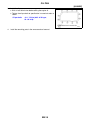
1
B ENGINE
A
SECTION
ENGINE MECHANICAL
EM
C
D
CONTENTS
KA24DE
PRECAUTIONS .......................................................... 4
Precautions for Supplemental Restraint System
(SRS) “AIR BAG” and “SEAT BELT PRE-TENSIONER” .................................................................. 4
Parts Requiring Angular Tightening ......................... 4
Precautions for Liquid Gasket .................................. 5
REMOVAL OF LIQUID GASKET SEALING .......... 5
LIQUID GASKET APPLICATION PROCEDURE..... 5
PREPARATION ........................................................... 6
Special Service Tools ............................................... 6
Commercial Service Tools ........................................ 8
NOISE, VIBRATION, AND HARSHNESS (NVH)
TROUBLESHOOTING ...............................................11
Noise, Vibration and Harshness (NVH) ...................11
NVH TROUBLESHOOTING CHART — ENGINE
NOISE ................................................................. 12
OUTER COMPONENT PARTS ................................ 13
Removal and Installation ........................................ 13
OIL PAN .................................................................... 16
Components ........................................................... 16
Removal ................................................................. 16
Installation .............................................................. 17
TIMING CHAIN ......................................................... 19
Components ........................................................... 19
LIQUID GASKET APPLICATION PLACES ......... 20
Removal ................................................................. 20
UPPER TIMING CHAIN ...................................... 21
IDLER SPROCKET ............................................. 21
LOWER TIMING CHAIN ..................................... 22
Inspection ............................................................... 24
Installation .............................................................. 24
LOWER TIMING CHAIN ..................................... 24
IDLER SPROCKET ............................................. 26
UPPER TIMING CHAIN ...................................... 26
OIL SEAL .................................................................. 28
Replacement .......................................................... 28
VALVE OIL SEAL ................................................ 28
FRONT OIL SEAL ............................................... 28
REAR OIL SEAL ................................................. 30
CYLINDER HEAD ..................................................... 32
On-Vehicle Service ................................................. 32
CHECKING COMPRESSION PRESSURE ......... 32
Components ........................................................... 33
Removal ................................................................. 33
Disassembly ........................................................... 34
Inspection ............................................................... 34
CYLINDER HEAD DISTORTION ........................ 34
CAMSHAFT VISUAL CHECK ............................. 35
CAMSHAFT RUNOUT ........................................ 35
CAMSHAFT CAM HEIGHT ................................. 35
CAMSHAFT JOURNAL CLEARANCE ................ 36
CAMSHAFT END PLAY ...................................... 36
CAMSHAFT SPROCKET RUNOUT .................... 36
VALVE GUIDE CLEARANCE .............................. 37
VALVE GUIDE REPLACEMENT ......................... 37
VALVE SEATS ..................................................... 39
REPLACING VALVE SEAT ................................. 39
VALVE DIMENSIONS .......................................... 40
VALVE SPRING ................................................... 40
VALVE LIFTER AND ADJUSTING SHIM ............ 41
Assembly ................................................................ 42
Installation .............................................................. 42
Valve Clearance ..................................................... 43
CHECKING ......................................................... 43
ADJUSTING ........................................................ 44
ENGINE ASSEMBLY ................................................ 46
Removal and Installation ........................................ 46
REMOVAL ........................................................... 47
INSTALLATION ................................................... 47
CYLINDER BLOCK .................................................. 48
Components ........................................................... 48
Removal and Installation ........................................ 49
Disassembly ........................................................... 49
PISTON AND CRANKSHAFT ............................. 49
Inspection ............................................................... 50
PISTON AND PISTON PIN CLEARANCE .......... 50
PISTON RING SIDE CLEARANCE ..................... 51
PISTON RING END GAP .................................... 51
CONNECTING ROD BEND AND TORSION ...... 51
EM-1
E
F
G
H
I
J
K
L
M
CYLINDER BLOCK DISTORTION AND WEAR... 52
PISTON-TO-CYLINDER BORE CLEARANCE ... 52
CRANKSHAFT .................................................... 53
BEARING CLEARANCE ..................................... 54
CONNECTING ROD BUSHING CLEARANCE
(SMALL END) ...................................................... 57
REPLACEMENT OF CONNECTING ROD
BUSHING (SMALL END) .................................... 58
FLYWHEEL/DRIVE PLATE RUNOUT ................. 58
Assembly ................................................................ 58
PISTON ............................................................... 58
CRANKSHAFT .................................................... 60
REPLACING PILOT BUSHING ........................... 61
SERVICE DATA AND SPECIFICATIONS (SDS) ...... 63
General Specifications ............................................ 63
COMPRESSION PRESSURE ............................. 63
Cylinder Head ......................................................... 63
Valve ....................................................................... 63
VALVE .................................................................. 63
VALVE SPRING ................................................... 64
VALVE GUIDE ..................................................... 64
VALVE LIFTER .................................................... 64
VALVE CLEARANCE ADJUSTMENT ................. 65
AVAILABLE SHIMS ............................................. 65
VALVE SEAT ....................................................... 66
Cylinder Block ......................................................... 67
Camshaft and Camshaft Bearing ........................... 68
Piston, Piston Ring and Piston pin ......................... 69
PISTON ............................................................... 69
PISTON PIN ........................................................ 69
PISTON RING ..................................................... 69
Connecting Rod ...................................................... 70
Crankshaft .............................................................. 70
Bearing Clearance .................................................. 71
Available Main Bearing ........................................... 71
STANDARD ......................................................... 71
UNDERSIZE (SERVICE) ..................................... 71
Available Connecting Rod Bearing ......................... 71
STANDARD ......................................................... 71
UNDERSIZE (SERVICE) ..................................... 71
Miscellaneous Components .................................... 71
VG33E and VG33ER
PRECAUTIONS ......................................................... 72
Precautions for Supplemental Restraint System
(SRS) “AIR BAG” and “SEAT BELT PRE-TENSIONER” ................................................................. 72
Parts Requiring Angular Tightening ........................ 72
Precautions for Liquid Gasket ................................ 73
REMOVAL OF LIQUID GASKET SEALING ........ 73
LIQUID GASKET APPLICATION PROCEDURE... 73
PREPARATION ......................................................... 74
Special Service Tools ............................................. 74
Commercial Service Tools ...................................... 76
NOISE, VIBRATION, AND HARSHNESS (NVH)
TROUBLESHOOTING .............................................. 78
Noise, Vibration and Harshness (NVH) .................. 78
NVH TROUBLESHOOTING CHART — ENGINE
NOISE ..................................................................79
OUTER COMPONENT PARTS .................................80
Removal and Installation .........................................80
OIL PAN .....................................................................88
Removal ..................................................................88
Installation ...............................................................89
TIMING BELT ............................................................91
Components ............................................................91
Removal ..................................................................91
Inspection ................................................................93
BELT TENSIONER AND TENSIONER SPRING...94
Installation ...............................................................94
Tension Adjustment .................................................95
AFTER BELT REPLACEMENT ...........................95
AFTER ENGINE OVERHAUL OR ENGINE
REASSEMBLY (WITH ROCKER COVERS
REMOVED) ..........................................................96
OIL SEAL ..................................................................99
Replacement ...........................................................99
VALVE OIL SEAL .................................................99
CAMSHAFT OIL SEAL ........................................99
FRONT OIL SEAL .............................................. 100
REAR OIL SEAL ................................................ 101
CYLINDER HEAD ................................................... 102
Measurement of Compression .............................. 102
Components .......................................................... 104
Removal ................................................................ 105
Disassembly .......................................................... 108
Inspection .............................................................. 110
CYLINDER HEAD DISTORTION ....................... 110
CAMSHAFT VISUAL CHECK ............................ 110
CAMSHAFT RUNOUT ....................................... 110
CAMSHAFT CAM HEIGHT ................................ 110
CAMSHAFT JOURNAL CLEARANCE .............. 111
CAMSHAFT END PLAY ..................................... 111
CAMSHAFT SPROCKET RUNOUT .................. 111
VALVE GUIDE CLEARANCE ............................ 112
VALVE GUIDE REPLACEMENT ....................... 113
VALVE SEATS ................................................... 114
REPLACING VALVE SEAT FOR SERVICE
PARTS ............................................................... 114
VALVE DIMENSIONS ........................................ 115
VALVE SPRING ................................................. 115
ROCKER SHAFT AND ROCKER ARM ............. 116
HYDRAULIC VALVE LIFTER ............................. 116
Assembly .............................................................. 117
Installation ............................................................. 118
SUPERCHARGER .................................................. 124
Components .......................................................... 124
Removal ................................................................ 125
Inspection .............................................................. 126
SUPERCHARGER FLANGE ............................. 126
ROTOR SYSTEM .............................................. 126
SUPERCHARGER BYPASS VALVE ACTUATOR ................................................................... 126
Installation ............................................................. 127
EM-2
ENGINE ASSEMBLY .............................................. 128
Removal and Installation ...................................... 128
REMOVAL ......................................................... 129
INSTALLATION ................................................. 130
CYLINDER BLOCK ................................................ 131
Components ......................................................... 131
Removal and Installation ...................................... 132
Disassembly ......................................................... 132
PISTON AND CRANKSHAFT ........................... 132
Inspection ............................................................. 133
PISTON AND PISTON PIN CLEARANCE ........ 133
PISTON RING SIDE CLEARANCE .................. 133
PISTON RING END GAP .................................. 134
CONNECTING ROD BEND AND TORSION .... 134
CYLINDER BLOCK DISTORTION AND WEAR. 134
PISTON-TO-BORE CLEARANCE .................... 135
CRANKSHAFT .................................................. 136
BEARING CLEARANCE ................................... 137
CONNECTING ROD BUSHING CLEARANCE
(SMALL END) ................................................... 140
REPLACEMENT OF CONNECTING ROD
BUSHING (SMALL END) .................................. 140
FLYWHEEL/DRIVE PLATE RUNOUT ............... 140
Assembly .............................................................. 141
PISTON ............................................................. 141
CRANKSHAFT .................................................. 141
REPLACING PILOT BUSHING (M/T) OR PILOT
CONVERTER (A/T) ........................................... 143
SERVICE DATA AND SPECIFICATIONS (SDS) .... 144
General Specifications .......................................... 144
Cylinder Head ....................................................... 145
Valve ..................................................................... 145
VALVE ............................................................... 145
VALVE SPRING ................................................. 145
HYDRAULIC VALVE LIFTER ............................ 146
VALVE GUIDE ................................................... 146
ROCKER SHAFT AND ROCKER ARM ............ 146
Valve Seat ............................................................ 147
INTAKE VALVE SEAT ........................................ 147
EXHAUST VALVE SEAT ................................... 148
Camshaft and Camshaft Bearing ......................... 148
Cylinder Block ....................................................... 149
Piston, Piston Ring and Piston Pin ....................... 150
AVAILABLE PISTON ......................................... 150
PISTON RING ................................................... 150
PISTON PIN ...................................................... 151
Connecting Rod .................................................... 151
Crankshaft ............................................................ 152
Available Main Bearing ......................................... 153
NO. 1 MAIN BEARING ...................................... 153
NO. 2 AND 3 MAIN BEARING .......................... 153
NO. 4 MAIN BEARING ...................................... 153
UNDER SIZE ..................................................... 153
Available Connecting Rod Bearing ....................... 154
CONNECTING ROD BEARING UNDERSIZE . 154
Miscellaneous Components ................................. 154
BEARING CLEARANCE ................................... 154
A
EM
C
D
E
F
G
H
I
J
K
L
M
EM-3
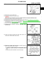
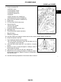
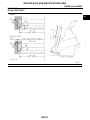
PRECAUTIONS
[KA24DE]
PFP:00001
PRECAUTIONS
Precautions for Supplemental Restraint System (SRS) “AIR BAG” and “SEAT
BELT PRE-TENSIONER”
EBS00GS0
The Supplemental Restraint System such as “AIR BAG” and “SEAT BELT PRE-TENSIONER”, used along
with a front seat belt, helps to reduce the risk or severity of injury to the driver and front passenger for certain
types of collision. This system may include seat belt switch inputs and dual stage front air bag modules. If
equipped with dual stage front air bag modules, the SRS system uses the seat belt switches to determine the
front air bag deployment, and may only deploy one front air bag, depending on the severity of a collision and
whether the front occupants are belted or unbelted. Information necessary to service the system safely is
included in the SRS and SB section of this Service Manual.
The vehicle may be equipped with a passenger air bag deactivation switch. Because no rear seat exists where
a rear-facing child restraint can be placed, the switch is designed to turn off the passenger air bag so that a
rear-facing child restraint can be used in the front passenger seat. The switch is located in the center of the
instrument panel, near the ashtray. When the switch is turned to the ON position, the passenger air bag is
enabled and could inflate for certain types of collision. When the switch is turned to the OFF position, the passenger air bag is disabled and will not inflate. A passenger air bag OFF indicator on the instrument panel lights
up when the passenger air bag is switched OFF. The driver air bag always remains enabled and is not affected
by the passenger air bag deactivation switch.
WARNING:
●
To avoid rendering the SRS inoperative, which could increase the risk of personal injury or death
in the event of a collision which would result in air bag inflation, all maintenance must be performed by an authorized NISSAN/INFINITI dealer.
●
Improper maintenance, including incorrect removal and installation of the SRS, can lead to personal injury caused by unintentional activation of the system. For removal of Spiral Cable and Air
Bag Module, see the SRS section.
●
Do not use electrical test equipment on any circuit related to the SRS unless instructed to in this
Service Manual. SRS wiring harnesses can be identified by yellow and/or orange harnesses or
harness connectors.
●
The vehicle may be equipped with a passenger air bag deactivation switch which can be operated
by the customer. When the passenger air bag is switched OFF, the passenger air bag is disabled
and will not inflate. When the passenger air bag is switched ON, the passenger air bag is enabled
and could inflate for certain types of collision. After SRS maintenance or repair, make sure the
passenger air bag deactivation switch is in the same position (ON or OFF) as when the vehicle
arrived for service.
Parts Requiring Angular Tightening
●
–
–
●
●
●
EBS00GS1
Use an angle wrench for the final tightening of the following engine parts:
Cylinder head bolts
Connecting rod cap nuts
Do not use a torque value for final tightening.
The torque value for these parts are for a preliminary step.
Ensure thread and seat surfaces are clean and coated with engine oil.
EM-4
PRECAUTIONS
[KA24DE]
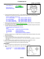
Precautions for Liquid Gasket
EBS00GS2
A
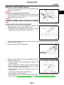
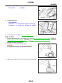
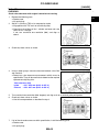
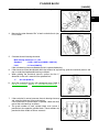
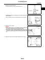
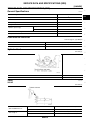
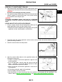
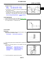
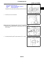
REMOVAL OF LIQUID GASKET SEALING
After removing the mounting bolts and nuts, disconnect the component using a seal cutter.
CAUTION:
Be careful not to damage the mating surfaces.
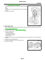
●
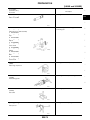
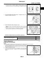
Use a plastic hammer to lightly tap (1) the areas where the liquid
gasket is applied. To advance the cutter, use a plastic hammer
(2) to slide the cutter along the joint.
CAUTION:
If for some unavoidable reason a tool such as a flat-bladed
screwdriver is used, be careful not to damage the mating surfaces.
●
EM
C
D
PBIC0275E
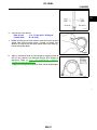
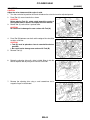
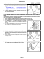
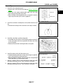
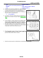
LIQUID GASKET APPLICATION PROCEDURE
1.
E
Using a scraper, remove the old liquid gasket adhering to the
gasket application surface and the mating surface.
● Remove the sealant completely from the groove of the gasket
application surface, mounting bolts, and bolt holes.
F
G
H
PBIC0003E
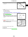
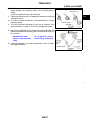
2.
3.
Thoroughly clean the gasket application surface and the mating surface and remove adhering moisture,
grease and foreign materials.
Attach the sealant tube to the tube presser.
I
J
K
L
EMA0622D
4.
Apply the sealant without breaks to the specified location with
the specified dimensions.
● If there is a groove for the sealant application, apply the sealant to the groove.
● As for the bolt holes, normally apply the sealant inside the
holes. If specified, it should be applied outside the holes.
Make sure to read the text of this manual.
● Within five minutes of the sealant application install the mating component.
● If the sealant protrudes, wipe it off immediately.
SEM159F
● Do not retighten after the installation.
● After 30 minutes or more have passed from the installation, fill the engine with the specified oil and
coolant. Refer to MA-20, "Changing Engine Oil" and MA-17, "REFILLING ENGINE COOLANT" .
EM-5
M
PREPARATION
[KA24DE]
PREPARATION
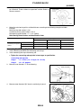
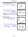
Special Service Tools
PFP:00002
EBS00GS3
The actual shapes of Kent-Moore tools may differ from those of the special service tools illustrated here.
Tool number
(Kent-Moore No.)
Description
Tool name
ST0501S000
(
—
)
Engine stand assembly
1 ST05011000
(
—
)
Engine stand
2 ST05012000
(
—
)
Base
Disassembling and assembling
NT042
KV10105001
(
—
)
Engine attachment
NT031
KV101092S0
(J26336-B)
Valve spring compressor
1 KV10109210
(
—
)
Compressor
2 KV100109220
(
—
)
Adapter
Disassembling and assembling valve components
WEM044
KV10112100
(BT8653-A)
Angle wrench
Tightening bearing cap, cylinder head bolts,
etc.
NT014
KV10116300
(J-38955)
Valve oil seal drift
Installing valve oil seal
a: 25 (0.98) dia.
b: 14.4 (0.567) dia.
c: 11.8 (0.465) dia.
d: 10 (0.39) dia.
e: 11 (0.43)
f: 9 (0.35)
WEM151
EM-6
PREPARATION
[KA24DE]
Tool number
(Kent-Moore No.)
Tool name
KV10110300
(
—
)
Piston pin press stand assembly
1 KV10110310
(
—
)
Cap
2 KV10110330
(
—
)
Spacer
3 ST13030020
(
—
)
Press stand
4 ST13030030
(
—
)
Spring
5 KV10110340
(
—
)
Drift
6 KV10110320
(
—
)
Center shaft
Description
Disassembling and assembling piston with
connecting rod
A
EM
C
D
E
WEM150
F
G
EM03470000
(J-8037)
Piston ring compressor
Installing piston assembly into cylinder bore
H
I
NT044
(J-36467)
Valve oil seal remover
Removing valve oil seal
J
K
NT034
ST16610001
(J-23907)
Pilot bushing puller
Removing crankshaft pilot bushing
L
M
NT045
KV10111100
(J-37228)
Seal cutter
Removing oil pan
NT046
WS39930000
(
—
Tube presser
Pressing the tube of liquid gasket
)
NT052
EM-7
PREPARATION
[KA24DE]
Tool number
(Kent-Moore No.)
Tool name
KV101151S0
(J-38972)
Lifter stopper set
1 KV10115110
(J-38972-1)
Camshaft pliers
2 KV10115120
(J-38972-2)
Lifter stopper
Description
Changing valve lifter shims
S-NT041
KV10117100
(J-36471-A)
Front heated oxygen sensor wrench
Loosening or tightening heated oxygen sensor
For 22 mm (0.87 in) hexagon nut
NT379
KV10114700
(J-38139)
Main bearing cap remover
Removing crankshaft main bearing cap
For No. 3 and No. 5 bearings
ZZA0023D
—
(J-45499)
Ring gear stopper
Preventing crankshaft rotation
LBIA0362E
Commercial Service Tools
EBS00GS4
Tool name
(Kent-Moore No.)
Description
Spark plug wrench
Removing and installing spark plug
NT047
Pulley holder
Holding camshaft pulley while tightening or
loosening camshaft bolt
NT035
EM-8
PREPARATION
[KA24DE]
Tool name
(Kent-Moore No.)
Description
Valve seat cutter set
Finishing valve seat dimensions
A
EM
C
NT048
Piston ring expander
Removing and installing piston ring
D
E
NT030
Valve guide drift
Removing and installing valve guide
Intake & Exhaust:
a = 10.5 mm (0.413 in) dia.
b = 6.6 mm (0.260 in) dia.
F
G
NT015
Valve guide reamer
NT016
Front oil seal drift
Reaming valve guide 1 or hole for oversize
valve guide 2
Intake:
d1 = 7.0 mm (0.276 in) dia.
d2 = 11.2 mm (0.441 in) dia.
Exhaust:
d1 = 8.0 mm (0.315 in) dia.
d2 = 12.2 mm (0.480 in) dia.
Installing front oil seal
a: 52 mm (2.05 in) dia.
b: 44 mm (1.73 in) dia.
H
I
J
K
L
NT049
Rear oil seal drift
Installing rear oil seal
a: 46 mm (1.81 in)
b: 110 mm (4.33 in)
c: 84 mm (3.31 in)
d: 96 mm (3.78 in)
WEM152
Thread repair tool for oxygen sensor
a: (J-43897-18)
b: (J-43897-12)
a: 18 mm (0.71 in)
b: 12 mm (0.47 in)
AEM488
EM-9
M
PREPARATION
[KA24DE]
Tool name
(Kent-Moore No.)
Description
Anti-seize thread compound
For preventing corrosion, seizing, and galling
on high temperature applications.
AEM489
Crankshaft pulley puller
Removing crankshaft pulley
PBIC0887E
EM-10
NOISE, VIBRATION, AND HARSHNESS (NVH) TROUBLESHOOTING
[KA24DE]
NOISE, VIBRATION, AND HARSHNESS (NVH) TROUBLESHOOTING
Noise, Vibration and Harshness (NVH)
PFP:00003
A
EBS00GS5
EM
C
D
E
F
G
H
I
J
K
L
M
AEM466
EM-11
NOISE, VIBRATION, AND HARSHNESS (NVH) TROUBLESHOOTING
[KA24DE]
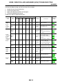
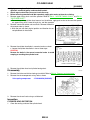
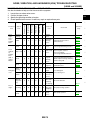
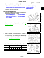
NVH TROUBLESHOOTING CHART — ENGINE NOISE
Use the chart below to help you find the cause of the symptom.
1. Locate the area where noise occurs.
2. Confirm the type of noise.
3. Specify the operating condition of the engine.
4. Check the specified noise source.
If necessary, repair or replace these parts.
Operating condition of engine
Location of
noise
Top of
engine
Rocker
cover
Cylinder
head
Type of
noise
Front of
engine
Timing
chain
cover
Front of
engine
Reference
page
After
warmup
When
starting
When
idling
Whe
n revving
While
driving
Ticking or
clicking
C
A
—
A
B
—
Tappet
noise
Valve clearance
EM-37
Rattle
C
A
—
A
B
C
Camshaft
bearing
noise
Camshaft journal clearance
Camshaft runout
EM-36
—
Piston pin
noise
Piston and piston pin clearance
Connecting rod bushing
clearance
EM-50, or
EM-57
A
Piston slap
noise
Piston ring side clearance
Piston ring end gap
Connecting rod bend and
torsion
Piston-to-bore clearance
EM-51,
EM-51 ,
EM-51 , or
EM-52
Connecting rod bearing
clearance (Big end)
Connecting rod bushing
clearance (Small end)
EM-56, or
EM-57
Slap or
knock
Crankshaft pulley
Cylinder
block
(upper side
of engine)
Oil pan
Source of
noise
Before
warmup
—
Slap or
rap
A
A
—
—
—
B
B
B
B
Check item
Knock
A
B
C
B
B
B
Connecting rodbearing
noise
Knock
A
B
—
A
B
C
Main bearing noise
Crankshaft runout
Main bearing oil clearance
EM-53, or
EM-54
Timing chain cracks and
wear
EM-24
Tapping or
ticking
A
A
—
B
B
B
Timing
chain and
chain tensioner
noise
Squeaking or fizzing
A
B
—
B
—
C
Drive belts
(Sticking or
slipping)
Drive belt deflection
Creaking
A
B
A
B
A
B
Drive belts
(Slipping)
Idler pulley bearing operation
Squall
creak
A
B
—
B
A
B
Water
pump
noise
Water pump operation
A: Closely related
B: Related
C: Sometimes related
—: Not related:
EM-12
MA-16,
"DRIVE
BELT
DEFLECTION AND
TENSION"
CO-11,
"Inspection"
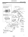
OUTER COMPONENT PARTS
[KA24DE]
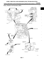
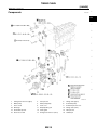
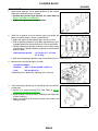
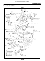
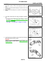
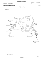
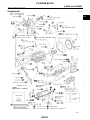
OUTER COMPONENT PARTS
Removal and Installation
PFP:00100
A
EBS00GS6
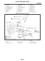
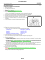
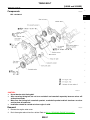
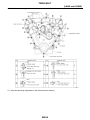
Engine Outer Components
EM
C
D
E
F
G
H
I
J
K
L
M
WBIA0232E
EM-13
OUTER COMPONENT PARTS
[KA24DE]
1.
Throttle body
2.
EGR temperature sensor
4.
EGR tube
5.
Oil dipstick
6.
Exhaust manifold
7.
Heated oxygen sensor 1
8.
Exhaust manifold cover
9.
TWC (manifold)
10. TWC (manifold) gaskets
11. Exhaust manifold gaskets
3.
EGR valve
12. Crankshaft pulley
13. Generator bracket
14. Generator
15. Water pump
16. Adjusting bar
17. Water pump pulley
18. Oil pressure switch
19. Oil filter
20. Oil filter bracket
21. Knock sensor
22. Water inlet
23. Thermostat
24. Intake manifold bracket
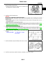
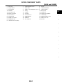
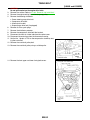
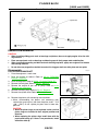
Ignition System Outer Components
WBIA0180E
1.
Spark plug
2.
Ignition wires
3.
Camshaft position sensor built into
distributor
4.
EGR tube
5.
Exhaust manifold
6.
Heated oxygen sensor 1
7.
Exhaust manifold cover
8.
TWC (manifold)
9.
TWC (manifold) gaskets
EM-14
OUTER COMPONENT PARTS
[KA24DE]
A
EM
C
D
E
F
G
H
I
WBIA0099E
J
K
L
M
EM-15
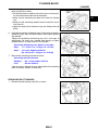
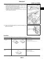
OIL PAN
[KA24DE]
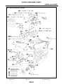
OIL PAN
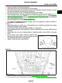
Components
PFP:11110
EBS00GS7
WBIA0174E
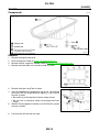
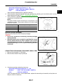
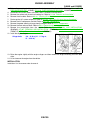
Removal
1.
2.
3.
4.
EBS00GS8
Remove the engine under cover.
Drain the engine oil. Refer to MA-20, "Changing Engine Oil" .
Remove the front suspension member. Refer to FSU-10, "Front Suspension Parts" .
Remove the oil pan bolts in the numerical order as shown.
AEM497
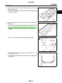
5.
a.
b.
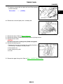
Remove the oil pan using Tool as shown.
Insert Tool between the cylinder block and oil pan, and separate
the oil pan from the engine block by tapping (1) with a plastic
hammer as shown.
● Be careful not to damage the aluminum mating surface.
● Do not insert a screwdriver, which may damage the oil pan
flange.
Slide the Tool by tapping on the side (2) of the Tool with a plastic
hammer as shown.
PBIC0002E
6.
Pull the oil pan out from the front side.
EM-16
OIL PAN
[KA24DE]
Installation
1.
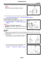
EBS00GS9
A
Use a scraper to remove the old liquid gasket from the mating
surface of the oil pan.
● Remove all traces of the liquid gasket from the mating surface
of the cylinder block.
EM
C
D
AEM299
2.
Apply a continuous bead of liquid gasket to the mating surface
of the oil pan.
● Use Genuine Anaerobic Liquid Gasket or equivalent. Refer to
MA-12, "RECOMMENDED FLUIDS AND LUBRICANTS" .
● Apply the liquid gasket to the groove on the oil pan mating
surface.
E
F
G
AEM300
H
●
Allow a 7 mm (0.28 in) clearance around the bolt holes.
I
J
K
SEM015E
●
●
Be sure the bead of liquid gasket has a diameter of 3.5 - 4.5
mm (0.138 - 0.177 in).
Installation must be done within 5 minutes after applying the
liquid gasket.
L
M
AEM301
EM-17
OIL PAN
[KA24DE]
3.
Install the oil pan.
● Wait at least 30 minutes before refilling the engine oil.
● Tighten the oil pan bolts to specification in numerical order as
shown.
Oil pan bolts
: 6.4 - 7.5 N·m (0.65 - 0.76 kg-m,
56 - 66 in-lb)
AEM498
4.
Install the remaining parts in the reverse order of removal.
EM-18
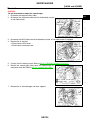
TIMING CHAIN
[KA24DE]
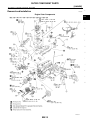
TIMING CHAIN
Components
PFP:13028
A
EBS00GSA
EM
C
D
E
F
G
H
I
J
K
L
M
WBIA0214E
1.
Timing chain tensioner (upper)
2.
Cam sprocket
3.
Timing chain (upper)
4.
Water pump
5.
Water pump pulley
6.
Crankshaft pulley
7.
Front oil seal
8.
Front cover
9.
Camshaft sprocket cover
11.
Oil pump drive gear
12. Timing chain (lower)
10. Oil slinger
13. Crankshaft sprocket
14. Chain guide
15. Idler sprocket
16. Chain tension arm
17. Timing chain tensioner (lower)
18. Suitable pin
EM-19
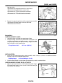
TIMING CHAIN
[KA24DE]
WEM135
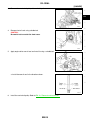
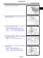
LIQUID GASKET APPLICATION PLACES
AEM479
Removal
EBS00GSB
CAUTION:
●
After removing timing chain, do not turn crankshaft and camshaft separately, or valves will strike
piston heads.
●
When installing chain tensioners or other sliding parts, lubricate contacting surfaces with new
engine oil.
●
Apply new engine oil to bolt threads and seat surfaces when installing camshaft sprockets and
crankshaft pulley.
●
Do not spill engine coolant on drive belts.
EM-20
TIMING CHAIN
[KA24DE]
UPPER TIMING CHAIN
1.
2.
3.
A
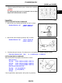
Remove the air cleaner assembly.
Remove the spark plug wires.
Set No.1 piston at TDC on its compression stroke.
EM
C
D
WEM067
4.
5.
6.
7.
Remove the vacuum hoses, electrical harness connectors, and harness clamps.
Remove the power steering belt.
Remove the power steering pump and position it to one side. Remove the idler pulley and bracket.
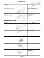
Remove the rocker cover, loosen and remove the rocker cover
bolts in the numerical order as shown.
E
F
G
H
I
AEM356
8.
J
Remove the camshaft sprocket cover.
K
L
AEM374
9.
Wipe off the links of the timing chain next to the timing marks on
the sprockets. Put paint marks on the timing chain, matching
them with the timing marks on the cam sprockets and idler
sprocket.
JEM547G
10. Remove cam sprocket bolts, cam sprockets and upper timing chain.
IDLER SPROCKET
1.
Remove upper timing chain.
EM-21
M
TIMING CHAIN
[KA24DE]
2.
3.
Refer to EM-21, "UPPER TIMING CHAIN" .
If not removing the lower cover, support lower timing chain using
a suitable tool to prevent the chain tensioner spring from coming
out.
NOTE:
This step is only to be applied when the lower cover is not being
removed.
Remove the idler sprocket.
AEM480
LOWER TIMING CHAIN
1.
2.
3.
4.
5.
6.
7.
8.
Drain the coolant by removing the cylinder block drain plug and opening the radiator drain cock. Refer to
MA-16, "Changing Engine Coolant" .
Drain the engine oil. Refer to MA-20, "Changing Engine Oil" .
Remove the intake air duct.
Remove the following parts:
● Generator drive belt
● A/C compressor drive belt
● Cooling fan with coupling
● Radiator shroud
Remove the A/C compressor without disconnecting the A/C hoses and position it to the side, supporting it
with wire.
Remove the idler pulley and bracket.
Set the No. 1 piston to TDC on its compression stroke.
Remove the distributor.
WEM067
EM-22
TIMING CHAIN
[KA24DE]
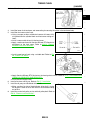
9.
Remove the crankshaft bolt.
● If necessary, remove the rear plact and install Tool to prevent
crankshaft rotation.
Tool number
:
—
A
(J-45499)
EM
C
LBIA0364E
D
10. Remove the crankshaft pulley with a suitable puller.
E
F
G
LEM115
11. Remove the oil pan. Refer to EM-16, "Removal" .
12. Remove the oil pump, distributor drive shaft, and the oil pickup strainer.
13. Remove the front cover.
CAUTION:
Be careful not to tear or damage the cylinder head gasket.
14. Remove the following parts.
● Release the timing chain tensioner by pushing the piston in
and inserting a suitable pin into the pin hole.
● Chain tension arm
● Lower timing chain guide
● Air duct
H
I
J
K
L
SEM796E
15. Remove the upper timing chain. Refer to EM-21, "UPPER TIMING CHAIN" .
EM-23
M
TIMING CHAIN
[KA24DE]
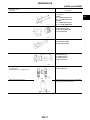
16. Wipe off the links of the timing chain next to the timing marks on
the sprockets. Put paint marks on the timing chain, matching
them with the timing marks on the crankshaft sprocket and idler
sprocket.
AEM482
17. Remove the lower timing chain, crankshaft sprocket, and idler sprocket.
Inspection
EBS00GSC
Check for cracks and excessive wear at the roller links. Replace the
chain if necessary.
AEM403
Installation
EBS00GSD
LOWER TIMING CHAIN
1.
Install crankshaft sprocket.
● Make sure that the mating marks of crankshaft sprocket face
the front of the engine.
SEM205C
2.
Install the idler sprocket and lower timing chain using the mating marks and the paint marks made during
the removal process.
CAUTION:
Be careful not to tear or damage the cylinder head gasket.
EM-24
TIMING CHAIN
[KA24DE]
3.
Install the chain guide and the chain tension arm.
A
EM
C
SEM796E
D
4.
5.
Install the lower chain tensioner and remove the pin securing the piston in the tensioner body.
Install the front cover and oil seal.
● Using a scraper or other suitable tool remove all traces of liquid gasket from the cylinder block and front cover mating surfaces.
● Install a new crankshaft seal in the front cover.
● Apply a continuous bead of Genuine Silicone RTV Sealant or
equivalent, to the front cover. Refer to MA-12, "Recommended Fluids and Lubricants" .
E
F
G
SEM715A
●
H
Install a new front oil seal using a suitable tool. Refer to EM28, "FRONT OIL SEAL" .
I
J
K
SEM292D
Apply Genuine Silicone RTV Sealant on the head gasket surface. Refer to GI-42, "RECOMMENDED
CHEMICAL PRODUCTS AND SEALANTS" .
● Install the front engine cover.
Install oil strainer and oil pan. Refer to EM-17, "Installation" .
Install the oil pump and distributor drive shaft.
● Make sure the flat side of the distributor drive shaft is facing
the engine. Failure to do so will result in the distributor being
out of time.
Install the crankshaft pulley and crankshaft pulley bolt. Refer to
EM-13, "Removal and Installation" .
●
6.
7.
8.
AEM391
EM-25
L
M
TIMING CHAIN
[KA24DE]
9.
If installed, remove Tool.
Tool number
:
—
(J-45499)
LBIA0364E
10. Install the rear plate.
Rear plate bolts
10 mm hex : 3 - 4 N·m (0.3 - 0.4 kg-m, 32 - 35 in-lb)
14 mm hex : 16 - 22 N·m (1.6 - 2.2 kg-m, 12 - 16 ft-lb)
LBIA0363E
11. Install the A/C compressor and idler pulley bracket. Refer to MTC-67, "Removal and Installation for Compressor" .
12. Install the radiator shroud and cooling fan with coupling. Refer to CO-14, "Removal and Installation" .
13. Install the A/C compressor, generator, and power steering pump drive belts. Refer to MA-15, "Checking
Drive Belts" .
14. Install the intake air duct.
IDLER SPROCKET
Install the lower timing chain. Refer to EM-24, "LOWER TIMING CHAIN" .
UPPER TIMING CHAIN
1.
Install the lower timing chain and idler sprocket. Refer to EM-24,
"LOWER TIMING CHAIN" and EM-26, "IDLER SPROCKET" .
SEM548G
2.
Install the upper timing chain and sprockets, aligning the paint
marks made during removal as shown.
SEM549G
EM-26
TIMING CHAIN
[KA24DE]
3.
Install the chain tensioner. Remove the pin holding the tensioner
piston in the bore of the tensioner.
● Check that the timing chain mating marks are aligned so that
the timing chain is correctly installed.
A
EM
C
JEM547G
D
4.
5.
6.
Install the camshaft sprocket cover:
CAUTION:
Do not to tear or damage the cylinder head gasket.
Do not let the upper timing chain slip or jump on the sprockets when installing the camshaft
sprocket cover.
● Use a scraper to remove all traces of liquid gasket from mating surfaces of the engine block and camshaft sprocket cover.
● Apply liquid gasket on the head gasket surface.
● Apply a continuous bead of liquid gasket to the cylinder head camshaft sprocket cover. Refer to EM-5,
"Precautions for Liquid Gasket" . Use Genuine Silicone RTV Sealant or equivalent. Refer to MA-12,
"Recommended Fluids and Lubricants" .
Install the rocker cover gasket on the rocker cover.
● Apply a continuous bead of liquid gasket to the cylinder head camshaft sprocket cover. Refer to EM-5,
"Precautions for Liquid Gasket" . Use Genuine Silicone RTV Sealant or equivalent. Refer to GI-42,
"RECOMMENDED CHEMICAL PRODUCTS AND SEALANTS"
Install the rocker cover. Tighten the bolts in the numerical order
as shown.
Rocker cover bolts
: 8 - 11 N·m (0.8 - 1.1 kg-m,
69 - 95 in-lb).
E
F
G
H
I
J
K
L
AEM357
7.
Install the distributor, align the distributor to the mark as shown.
M
WEM067
8.
Install the vacuum hoses, electrical harnesses, connectors, and harness clamps.
EM-27
OIL SEAL
[KA24DE]
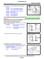
OIL SEAL
Replacement
PFP:00100
EBS00GSE
VALVE OIL SEAL
1.
2.
3.
4.
Remove the rocker cover.
Remove the camshaft. Refer to EM-19, "TIMING CHAIN" .
Remove valve spring and valve oil seal with Tool or a suitable tool.
NOTE:
The piston must be at TDC on the compression stroke to prevent the valve from falling into the combustion chamber.
Apply engine oil to new valve oil seal and install it with Tool.
SEM289D
●
The valve oil seal must be installed to specification over the
valve stem opening as shown.
SEM290D
FRONT OIL SEAL
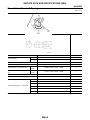
1.
2.
Remove radiator shroud. Refer to CO-14, "Components" .
Remove the crankshaft bolt.
● If necessary, remove the rear plact and install Tool to prevent
crankshaft rotation.
Tool number
:
—
(J-45499)
LBIA0364E
EM-28
OIL SEAL
[KA24DE]
3.
Remove the crankshaft pulley with a suitable puller.
A
EM
C
LEM115
D
4.
Remove front oil seal using suitable tool.
CAUTION:
Be careful not to scratch the front cover.
E
F
G
AEM385
5.
Apply engine oil to new oil seal and install it using a suitable tool.
H
I
J
SEM292D
●
K
Install the new oil seal in the direction shown.
L
M
SEM715A
6.
Install the crankshaft pulley. Refer to EM-13, "Removal and Installation" .
EM-29
OIL SEAL
[KA24DE]
7.
If installed, remove Tool.
Tool number
:
—
(J-45499)
LBIA0364E
8.
Install the rear plate.
Rear plate bolts
10 mm hex : 3 - 4 N·m (0.3 - 0.4 kg-m, 32 - 35 in-lb)
14 mm hex : 16 - 22 N·m (1.6 - 2.2 kg-m, 12 - 16 ft-lb)
LBIA0363E
9.
Install radiator shroud. Refer to CO-14, "Components" .
REAR OIL SEAL
1.
2.
3.
Remove the flywheel (M/T) or drive plate (A/T). Refer to MT-10, "Removal and Installation" (FS5W71C),
MT-48, "Removal and Installation" (FS5R30A), AT-62, "REMOVAL AND INSTALLATION" (RL4R01A),
AT-407, "REMOVAL AND INSTALLATION" (RE4R01A).
Remove the rear oil seal retainer.
Remove the rear oil seal from the retainer.
CAUTION:
Be careful not to scratch the rear oil seal retainer.
SEM895A
4.
Apply engine oil to new oil seal and install it using suitable tool.
SEM897A
EM-30
OIL SEAL
[KA24DE]
●
Install the new oil seal in the direction shown.
A
EM
C
SEM715A
D
5.
Install rear oil seal retainer.
Rear oil seal
retainer bolts
a.
: 6.4 - 7.5 N·m (0.65 - 0.76 kg-m,
56 - 66 in-lb)
E
Before installing rear oil seal retainer, remove all traces of liquid
gasket from mating surface using a scraper as shown. Also
remove all traces of the old liquid gasket from the mating surface of the cylinder block.
F
G
SEM896A
b.
Apply a continuous bead of liquid gasket to mating surface of
rear oil seal retainer. Use Genuine Silicone RTV Sealant or
equivalent. Refer to GI-42, "RECOMMENDED CHEMICAL
PRODUCTS AND SEALANTS" .
● Apply the liquid gasket around the inner side of the bolt holes.
H
I
J
AEM404
K
L
M
EM-31
CYLINDER HEAD
[KA24DE]
CYLINDER HEAD
On-Vehicle Service
PFP:11041
EBS00GSF
CHECKING COMPRESSION PRESSURE
1.
2.
3.
4.
5.
6.
7.
8.
9.
Warm up the engine.
Turn the ignition switch OFF.
Release the fuel pressure.
Refer to EC-46, "FUEL PRESSURE RELEASE" .
Remove all of the spark plugs.
● Clean area around plug with compressed air before removing the spark plug.
Disconnect the camshaft position sensor harness connector at the distributor.
Remove the fuel injector fuse No. 3 on FUSE BLOCK (J/B) behind the driver side instrument lower panel.
Attach a compression tester to the No. 1 cylinder as shown.
Depress the accelerator pedal fully to keep the throttle valve
wide open.
Crank the engine and record the highest gauge indication.
SEM486D
10. Repeat the measurement on each cylinder.
● Always use a fully-charged battery to obtain specified engine speed.
Compression
Standard
Minimum
Difference limit between cylinders
: kPa (kg/cm2 , psi)/300 rpm
: 1,226 (12.5, 178)
: 1,030 (10.5, 149)
: 98 (1.0, 14)
11. If the compression in one or more cylinders is low:
a. Pour a small amount of engine oil into the cylinders through the spark plug hole.
b. Retest the compression.
● If adding oil improves cylinder compression, piston rings may be worn or damaged. If so, replace piston
rings after checking piston.
● If pressure stays low, a valve may be sticking or seating improperly. Inspect and repair valve and valve
seat. Refer to EM-40, "VALVE DIMENSIONS" , EM-39, "VALVE SEATS" . If valve or valve seat is damaged excessively, replace it.
● If compression in any two cylinders adjacent cylinders is low, and if adding oil does not improve compression, there is leakage past the gasket surface. If so, replace cylinder head gasket.
12. Reinstall the spark plugs, fuel injector fuse, fuel pump fuse, and reconnect camshaft position sensor harness connector at the distributor.
13. Erase the DTC stored in the ECM.
Refer to EC-61, "HOW TO ERASE EMISSION-RELATED DIAGNOSTIC INFORMATION" .
CAUTION:
Always erase the DTC after checking compression.
EM-32
CYLINDER HEAD
[KA24DE]
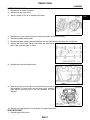
Components
EBS00GSG
A
EM
C
D
E
F
G
H
I
J
K
L
M
WBIA0233E
1.
Oil filler cap
2.
Rocker cover
3.
Camshaft bracket
4.
Intake camshaft
5.
Exhaust camshaft
6.
Adjusting shim
7.
Valve lifter
8.
Valve cotter
9.
Spring retainer
10. Valve spring
11. Spring seat
12. Valve oil seal
13. Intake valve
14. Exhaust valve
15. Cylinder head
16. Cylinder head bolt
17. Valve guide
18. Valve seat
19. Rocker cover gaskets
20. Cylinder head gasket
Removal
EBS00GSH
CAUTION:
●
When installing camshafts, chain tensioners, oil seals, or other sliding parts, lubricate contacting
surfaces with new engine oil.
EM-33
CYLINDER HEAD
[KA24DE]
●
●
●
1.
2.
Apply new engine oil to threads and seat surfaces when installing cylinder head, camshaft
sprocket, crankshaft pulley, and camshaft bracket.
Attach tags to valve lifters so as not to mix them up.
Before removing camshaft and idler sprockets, apply paint marks to them for re-timing.
Remove upper timing chain and idler sprocket. Refer to EM-21, "UPPER TIMING CHAIN" and EM-21,
"IDLER SPROCKET" .
● For re-timing during cylinder head removal and installation, apply paint marks to the camshaft sprockets, upper timing chain, lower timing chain, and idler sprocket.
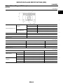
Remove camshaft brackets and camshafts. Remove the bolts in
the reverse order as shown.
● Mark the part with their original position and direction for correct placement for installation.
AEM352
3.
Remove the cylinder head bolts in numerical order as shown.
● Loosen the cylinder head bolts in two or three steps.
CAUTION:
Remove the bolts in the correct numerical order to avoid
warping or cracking the cylinder head.
SEM274D
4.
Remove the cylinder head and cylinder head gasket.
Disassembly
1.
2.
EBS00GSI
Remove the intake manifold and exhaust manifold. Refer to EM-13, "Removal and Installation" .
Remove the valve components using Tool as shown.
Valve spring compressor
: KV101092S0 (J26336-B)
SEM692D
3.
Remove the valve oil seals using a suitable tool.
Inspection
EBS00GSJ
CYLINDER HEAD DISTORTION
1.
Clean the sealing surface of the cylinder head.
EM-34
CYLINDER HEAD
[KA24DE]
2.
Use a reliable straightedge and feeler gauge to check the flatness of cylinder head surface. Check the cylinder head sealing
surface flatness along the six positions as shown.
A
Cylinder head surface flatness
Limit
: 0.1 mm (0.004 in)
EM
If it exceeds the limit, replace or resurface the cylinder head.
C
SEM294D
D
3.
Resurface the cylinder head as necessary to specification.
The limit of cylinder head resurfacing is determined by the cylinder block resurfacing:
Amount of cylinder head resurfacing is “A”.
Amount of cylinder block resurfacing is “B”.
Maximum limit
4.
E
: A + B = 0.2 mm (0.008 in)
After resurfacing, the cylinder head,
● Check that the camshaft rotates freely by hand. If resistance is felt, the cylinder head must be replaced.
Nominal cylinder head height
: 126.3 - 126.5 mm (4.972 - 4.980 in)
F
G
CAMSHAFT VISUAL CHECK
Check the camshaft for scratches, seizure, and wear.
H
CAMSHAFT RUNOUT
1.
Measure the camshaft runout at the center of the journal.
I
Runout (total indicator reading)
Standard
: less than 0.02 mm (0.0008 in)
Limit
: 0.04 mm (0.0016 in)
2.
J
If the camshaft runout exceeds the limit, replace the camshaft.
K
SEM926C
L
CAMSHAFT CAM HEIGHT
1.
Measure camshaft cam height.
Standard cam height
Intake
: 41.755 - 41.945 mm
(1.644 - 1.651 in)
Exhaust
: 41.815 - 42.005 mm
(1.646 - 1.654 in)
Cam height wear limit
Intake & Exhaust : 0.2 mm (0.008 in)
2.
M
If wear is beyond the limit, replace camshaft.
SEM549A
EM-35
CYLINDER HEAD
[KA24DE]
CAMSHAFT JOURNAL CLEARANCE
1.
2.
Install camshaft bracket and tighten bolts to the specified torque.
Measure inner diameter of camshaft bearing.
Standard inner diameter
No. 1 to No. 5 journals
: 28.000 - 28.025 mm
(1.1024 - 1.1033 in)
SEM295D
3.
Measure outer diameter of camshaft journal.
Standard outer diameter
No. 1 to No. 5 journals
: 27.935 - 27.955 mm
(1.0998 - 1.1006 in)
SEM012A
4.
If clearance exceeds the limit, replace camshaft and/or cylinder head.
Camshaft journal clearance
Standard
: 0.045 - 0.090 mm (0.0018 - 0.0035 in)
Limit
: 0.12 mm (0.0047 in)
CAMSHAFT END PLAY
1.
2.
Install camshaft in cylinder head.
Measure camshaft end play.
Camshaft end play
Standard
: 0.070 - 0.148 mm (0.0028 - 0.0058 in)
Limit
: 0.2 mm (0.008 in)
3.
4.
If end play exceeds the limit, replace camshaft and remeasure
camshaft end play.
If end play still exceeds the limit after replacing camshaft,
replace the cylinder head.
SEM296D
CAMSHAFT SPROCKET RUNOUT
1.
2.
Install sprocket on camshaft.
Measure camshaft sprocket runout.
Runout (total indicator reading)
Limit : 0.15 mm (0.0059 in)
3.
If it exceeds the limit, replace camshaft sprocket.
AEM328
EM-36
CYLINDER HEAD
[KA24DE]
VALVE GUIDE CLEARANCE
1.
A
Measure valve deflection as shown. Valve and valve guide
mostly wear in this direction.
Valve deflection limit (dial gauge reading)
Intake & Exhaust
: 0.2 mm (0.008 in)
EM
C
SEM297D
2.
a.
b.
If the valve exceeds the deflection limit, check the valve to valve
guide clearance:
Measure valve stem diameter and valve guide inner diameter.
Check that clearance is within specification.
Valve to valve guide clearance = valve guide inner diameter
- valve stem diameter.
D
E
F
Unit: mm (in)
Valve
Standard
Limit
Intake
0.020 - 0.053 (0.0008 - 0.0021)
0.08 (0.0031)
Exhaust
0.040 - 0.073 (0.0016 - 0.0029)
0.1 (0.004)
c.
d.
G
H
If the clearance exceeds the limit, replace the valve and remeasure the clearance.
If the clearance still exceeds the limit after replacing the valve,
replace the valve guide.
I
J
SEM298D
K
VALVE GUIDE REPLACEMENT
1.
To remove the valve guide, heat the cylinder head to 120° 140°C (248° - 284°F) by soaking in heated oil.
L
M
SEM008A
EM-37
CYLINDER HEAD
[KA24DE]
2.
To remove the valve guide, use a press [less than 20 kN (2 metric ton, 2.2 US ton, 2.0 Imp. ton) pressure] or hammer and suitable tool, to slide the valve guide out of the cylinder head.
SEM299D
3.
Ream the cylinder head valve guide hole.
Valve guide hole diameter (for service parts)
Intake & Exhaust
: 11.175 - 11.196 mm
(0.4400 - 0.4408 in)
SEM300D
4.
Heat cylinder head to 120° - 140°C (248° - 284°F) in heated oil
and press the replacement valve guide into the valve guide hole
in the cylinder head. Press the valve guide in to the specified
height "L" as shown.
Projection “L”
: 13.3 - 13.9 mm (0.524 - 0.547 in)
SEM301D
5.
Ream the new replacement valve guide.
Finished size
Intake & Exhaust
: 7.000 - 7.018 mm (0.2756 - 0.2763 in)
SEM300D
EM-38
CYLINDER HEAD
[KA24DE]
VALVE SEATS
A
Check valve seats for pitting at contact surface. Resurface or
replace if excessively worn.
●
Before repairing the valve seats, check the valves and valve
guides for wear as shown. If they are worn, replace them. Then
resurface the valve seat as necessary.
EM
C
SBIA0322E
●
Use both hands to resurface the valve seat uniformly using a
suitable tool, as shown.
D
E
F
G
SEM302D
H
REPLACING VALVE SEAT
1.
Bore out the old seat until it collapses. Boring should not continue beyond the bottom face of the seat recess in the cylinder
head. Set the machine depth stop to prevent damage.
I
J
K
SEM795A
2.
L
Ream the cylinder head valve seat recess.
Reaming bore for service valve seat
Oversize
: 0.5 mm (0.020 in)
Intake
: 38.000 - 38.016 mm (1.4961 - 1.4967 in)
Exhaust
: 32.700 - 32.716 mm (1.2874 - 1.2880 in)
3.
M
CAUTION:
Use the valve guide center for a reference point for reaming so the valve and valve seat will have
the correct fit.
Heat the cylinder head to 120° - 140°C (248° - 284°F) in heated
oil.
SEM008A
EM-39
CYLINDER HEAD
[KA24DE]
4.
5.
Press fit valve seat until it seats on the bottom of the recess.
Cut or grind valve seat using suitable tool to the specified dimensions.
Seat face “α”
: 45° 15′ - 45° 45′ degrees
Contacting width “W”
Intake
: 1.48 - 1.63 mm (0.0583 - 0.0642 in)
Exhaust
: 1.8 - 2.0 mm (0.071 - 0.079 in)
SEM892B
6.
7.
8.
After cutting, lap valve seat with abrasive compound.
Check the valve seat dimensions. Refer to EM-66, "VALVE SEAT" .
Use a depth gauge to measure the distance between the mounting surface of the cylinder head spring seat and the valve stem
end. If the distance is shorter than specified, repeat step 5
through 7 above, to adjust it. If it is longer, replace the valve seat
with a new one.
Valve seat resurface limit - height “L”
Intake
: 42.02 - 42.52 mm (1.6543 - 1.6740 in)
Exhaust
: 42.03 - 42.53 mm (1.6547 - 1.6744 in)
SEM621F
VALVE DIMENSIONS
Check dimensions of each valve. Refer to EM-63, "VALVE" . When
valve head has been worn down to less than the margin thickness
"T", replace the valve. Do not grind the valve stem more than the
grinding limit specification.
Margin thickness "T"
Valve stem tip grinding limit
: 0.5 mm (0.020 in)
: 0.2 mm (0.008 in)
SEM188A
VALVE SPRING
Squareness
1.
Measure the spring out-of-square dimension “S” as shown.
Out-of-square “S”
2.
: less than 2.2 mm (0.087 in)
If the out-of-square measurement exceeds the limit, replace the
spring.
SEM288A
EM-40
CYLINDER HEAD
[KA24DE]
Pressure
1.
Pressure
Standard
Limit
2.
A
Check the valve spring pressure at the specified spring height.
: N (kg, lb) at height mm (in)
: 418.0 (42.6, 93.9) at 29.17 (1.1484)
: 393.0 (40.1, 88.4) at 29.17 (1.1484)
EM
If not within specification, replace the spring.
C
EM113
D
VALVE LIFTER AND ADJUSTING SHIM
1.
Visually check the valve lifter and adjusting shim contact and
sliding surfaces for wear and scratches.
E
F
G
AEM499
2.
H
Check the diameter of the valve lifter as shown.
I
J
K
AEM502
3.
L
Check the diameter of the valve lifter guide bore as shown.
M
SEM303D
4.
If the measurements exceed the standard diameter or clearance, replace valve lifter or cylinder head as
necessary.
Valve lifter outer diameter
Lifter guide bore diameter
Valve lifter to valve lifter guide clearance
: 33.960 - 33.975 mm (1.3370 - 1.3376 in)
: 34.000 - 34.021 mm (1.3386 - 1.3394 in)
: 0.025 - 0.061 mm (0.0010 - 0.0024 in)
EM-41
CYLINDER HEAD
[KA24DE]
Assembly
1.
2.
EBS00GSK
Install valve component parts.
● Always use new valve oil seal. Refer to EM-28, "VALVE OIL
SEAL" .
● Before installing valve oil seal, install valve spring seat.
● Install outer valve spring (uneven pitch type) with its narrow
pitch side toward cylinder head side.
After installing the valve component parts, tap valve stem tip
with a plastic hammer to assure a proper fit.
SEM638B
Installation
1.
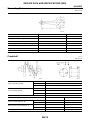
EBS00GSL
Tighten the cylinder head bolts in the numerical order as shown,
using the five step procedure:
SEM275D
Cylinder head bolt tightening steps:
Step "a"
: 29 N·m (3.0 kg-m, 22 ft-lb)
Step "b"
: 79 N·m (8.1 kg-m, 59 ft-lb)
Step "c"
: Loosen all bolts completely.
Step "d"
: 25 - 34 N·m (2.5 - 3.5 kg-m, 18 - 25 ft-lb)
Step "e"
: 86° - 91° degrees clockwise
NOTE:
If an angle wrench is not available, mark all of the cylinder head
bolts on the side facing engine front. Then turn each cylinder
head bolt to the specified angle.
2.
3.
SEM276D
Set camshafts and camshaft brackets.
● Set the dowel pins of both the intake and exhaust camshafts at 12 o'clock position when installing the
camshafts.
Tighten the camshaft bracket bolts in the order shown using two
steps:
● Apply new engine oil to bolt threads and seat surfaces.
Camshaft bracket bolt tightening steps
Step 1 : 2 N·m (0.2 kg-m, 17 in-lb)
Step 2 : 9 - 11.8 N·m (0.92 - 1.2 kg-m, 79.9 - 104.2 in-lb)
AEM352
4.
Install upper timing chain and idler sprocket. Refer to EM-26, "UPPER TIMING CHAIN" , EM-26, "IDLER
SPROCKET" .
EM-42
CYLINDER HEAD
[KA24DE]
Valve Clearance
EBS00GSM
A
CHECKING
Check valve clearance while engine is warm but not running.
1. Remove the following parts:
● Rocker cover
● All spark plugs
2. Set No. 1 cylinder at TDC on its compression stroke.
● Align pointer with TDC mark on crankshaft pulley.
● Check that valve lifters on No. 1 cylinder are loose and valve
lifters on No. 4 are tight.
If not, turn crankshaft one revolution (360°) and align as
above.
EM
C
D
E
WEM068
3.
F
Check only those valves as shown.
G
H
I
AEM382
4.
J
Using a feeler gauge, measure clearance between valve lifter
and camshaft.
● Record any valve clearance measurements which are out of
specification. They will be used later to determine the required
replacement adjusting shim.
K
Valve clearance (hot)
Intake
: 0.31 - 0.39 mm (0.012 - 0.015 in)
Exhaust : 0.39 - 0.47 mm (0.015 - 0.019 in)
L
SEM304D
5.
6.
Turn crankshaft one revolution (360° degrees) and align mark on crankshaft pulley with pointer.
Check only those valves as shown.
● Use the same procedure as described in step 4.
AEM383
7.
If all of the valve clearances are within specification, install the following parts:
● Rocker cover
● All spark plugs
EM-43
M
CYLINDER HEAD
[KA24DE]
ADJUSTING
CAUTION:
Adjust the valve clearance while engine is cold.
1. Turn the crankshaft to position the camshaft lobe on the valve that must be adjusted upward.
2. Place Tool (A) around camshaft as shown.
CAUTION:
Before placing Tool (A), rotate notch toward the center of
the cylinder head as shown, to simplify the shim removal.
3. Rotate Tool (A) so that lifter is pushed down.
CAUTION:
Be careful not to damage the cam surface with Tool (A).
SEM515EA
4.
5.
Place Tool (B) between camshaft and the edge of the valve lifter
to retain valve lifter.
CAUTION:
● Tool (B) must be placed as close to camshaft bracket as
possible.
● Be careful not to damage cam surface with Tool (B).
Remove Tool (A).
SEM516EA
6.
Rotate the adjusting shim until a hole is visible. Blow air into the
hole to separate the adjusting shim from the valve lifter.
AEM447
7.
Remove the adjusting shim using a small screwdriver and a
magnetic finger or suitable tool.
SEM517EA
EM-44
CYLINDER HEAD
[KA24DE]
8.
a.
Calculate the replacement adjusting shim size.
Using a micrometer to determine the thickness of the removed
adjusting shim.
A
EM
C
SEM145D
D
b.
Calculate the thickness of the new adjusting shim so that the valve clearance comes within the specified
values.
N = Thickness of new shim
R = Thickness of removed shim
M = Measured valve clearance
Intake and exhaust shim calculation
c.
: N = R + [M − 0.37 mm (0.0146 in)]
E
F
Select a new adjusting shim with the thickness as close as possible to the calculated value "N".
Refer to EM-65, "AVAILABLE SHIMS" .
NOTE:
Shims are available in thicknesses from 1.96 - 2.68 mm (0.0772
- 0.1055 in), in increments of 0.02 mm (0.0008 in). The adjusting
shim thickness is stamped on the bottom of the adjusting shim
as shown.
G
H
I
SEM308D
9.
Install the new adjusting shim using a suitable tool.
CAUTION:
Install the adjusting shim with the surface on which the
thickness is stamped facing down.
J
K
L
SEM518EA
10.
11.
12.
13.
Place Tool (A) as described in steps 2 through 4.
Remove Tool (B).
Remove Tool (A).
Recheck the valve clearance. Refer to EM-43, "Valve Clearance" .
EM-45
M
ENGINE ASSEMBLY
[KA24DE]
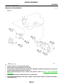
ENGINE ASSEMBLY
Removal and Installation
PFP:10001
EBS00GSN
WEM055
WARNING:
●
Position vehicle on a flat and solid surface.
●
Place chocks at front and back of rear wheels.
●
Do not remove engine until exhaust system has completely cooled off. Otherwise, you may burn
yourself and/or fire may break out in fuel line.
●
Before disconnecting fuel hose, release fuel pressure. Refer to EC-46, "FUEL PRESSURE
RELEASE" .
●
Be sure to hoist engine and transmission in a safe manner.
●
For engines not equipped with engine slingers, attach proper slingers and bolts described in
PARTS CATALOG.
EM-46
ENGINE ASSEMBLY
[KA24DE]
CAUTION:
●
When lifting engine, be sure to clear surrounding parts. Take special care near accelerator wire A
casing, brake lines and brake master cylinder.
●
In hoisting the engine, always use engine slingers in a safe manner.
●
Before separating engine and transmission, remove the crankshaft position sensor (OBD) from EM
the assembly.
●
Always take extra care not to damage edge of crankshaft position sensor (OBD) or ring gear teeth.
C
REMOVAL
1.
2.
3.
4.
5.
6.
7.
8.
9.
10.
11.
12.
13.
14.
15.
16.
Drain the coolant from engine block and radiator. Refer to MA-16, "Changing Engine Coolant" .
Release the fuel pressure. Refer to EC-46, "FUEL PRESSURE RELEASE" . Disconnect the fuel hose.
Remove the negative battery cable.
Remove the hood. Refer to EI-12, "Removal and Installation" .
Remove the air cleaner.
Remove the power steering drive belt, generator drive belt and A/C compressor drive belt.
Remove the radiator. Refer to CO-14, "Removal and Installation" .
Remove the exhaust manifold heat shield.
Disconnect the exhaust system at rear of TWC (manifold).
Remove the A/C compressor from bracket. Refer to MTC-67, "Removal and Installation for Compressor" .
Disconnect the accelerator wire, vacuum hoses, electrical connectors, heater hoses and vacuum booster
hose.
Remove the four power steering pump bolts.
Remove the transmission. Refer to MT-10, "Removal and Installation" (FS5W71C), MT-48, "Removal and
Installation" (FS5R30A), AT-62, "REMOVAL AND INSTALLATION" (RL4R01A), AT-407, "REMOVAL
AND INSTALLATION" (RE4R01A).
Install the engine slingers and attach engine lift hooks as shown.
Remove the LH and RH engine mounts.
Lift and remove the engine.
D
E
F
G
H
I
J
K
WBIA0111E
L
INSTALLATION
Installation is in the reverse order of removal.
M
EM-47
CYLINDER BLOCK
[KA24DE]
CYLINDER BLOCK
Components
PFP:11010
EBS00GSO
WBIA0181E
EM-48
CYLINDER BLOCK
[KA24DE]
1.
Block heater
2.
Drain plug
3.
Cylinder block
4.
Rear oil seal retainer
5.
Rear oil seal
6.
Drive plate reinforcement (A/T)
7.
Drive plate (A/T)
8.
Rear plate (A/T)
9.
Pilot converter (A/T)
10. Dust cover (A/T)
11. Flywheel (M/T)
12. Rear plate (M/T)
13. Pilot bushing (M/T)
14. Main bearing cap
15. Main bearing
16. Connecting rod bearing
17. Connecting rod
18. Snap ring
19. Piston pin
20. Piston
21. Piston rings
22. Crankshaft
23. Oil strainer
24. Oil jet
A
EM
C
25. Oil seal
Removal and Installation
1.
2.
EBS00GSP
To remove the cylinder block for disassembly, remove the engine. Refer to EM-46, "Removal and Installation" .
CAUTION:
● When installing sliding parts, lubricate the contacting surfaces with new engine oil.
● Place removed parts such as bearings and bearing caps in their proper order and direction.
● When installing connecting rod nuts and main bearing cap bolts, apply new engine oil to the
threads and seating surfaces.
● Do not allow any magnetic materials to contact the ring gear teeth of the flywheel or drive plate.
Installation is in the reverse order of removal.
Disassembly
E
F
G
EBS00GSQ
PISTON AND CRANKSHAFT
1.
2.
3.
4.
5.
6.
D
H
Place the engine on a work stand.
Remove the oil pan. Refer to EM-16, "Removal" .
Remove the timing chain. Refer to EM-20, "Removal" .
Remove the water pump. Refer to CO-10, "Removal" .
Remove the cylinder head. Refer to EM-33, "Removal" .
Remove the pistons with connecting rods.
CAUTION:
Use care not to scratch the engine block cylinder bore
when removing the piston and connecting rod assemblies.
I
J
K
SEM744
7.
a.
Remove bearing caps in the numerical order as shown, and
remove the crankshaft.
Loosen the main bearing cap bolts in several steps in the
numerical order as shown.
● Before removing the main bearing caps, mark the location
and direction on each cap and bolt for correct placement for
installation.
● Before removing the main bearing cap bolts, measure crankshaft end play. Refer to EM-53, "CRANKSHAFT" .
L
M
EEM118
EM-49
CYLINDER BLOCK
[KA24DE]
b.
Using the main bearing cap bolts, remove the main bearing cap
while shaking it right and left as shown.
● Remove the No. 3 and No. 5 main bearing caps using Tool.
Main Bearing Cap Remover
: KV10114700 (J-38139)
EMI0552D
8.
9.
Remove the crankshaft.
Remove the main bearings from the cylinder block journals and the main bearing caps.
CAUTION:
Before removal, mark the main bearings with their location and direction for installation into their
original position.
10. Remove the oil jets.
Inspection
EBS00GSR
PISTON AND PISTON PIN CLEARANCE
1.
Measure the inner diameter of piston pin hole “dp”.
Standard diameter “dp”
: 20.993 - 21.005 mm
(0.8265 - 0.8270 in)
AEM023
2.
Measure the outer diameter of piston pin “Dp”.
Standard diameter “Dp”
: 20.989 - 21.001 mm
(0.8263 - 0.8268 in)
AEM024
3.
Calculate the piston pin clearance.
Piston pin clearance
: dp − Dp = (−0.002) - 0.01 mm [(−0.0001) - 0.0004 in]
If it exceeds the above value, replace piston and pin assembly.
EM-50
CYLINDER BLOCK
[KA24DE]
PISTON RING SIDE CLEARANCE
A
Measure the piston ring side clearance as shown. If the clearance
exceeds the specification, replace piston ring.
If the clearance exceeds the maximum side clearance limit with the
new piston ring, replace piston.
Side Clearance
Top ring
2nd ring
Oil ring
Limit (Top, 2nd)
EM
: 0.04 - 0.08 mm (0.0016 - 0.0031 in)
: 0.03 - 0.07 mm (0.0012 - 0.0028 in)
: 0.065 - 0.135 mm (0.0026 - 0.0053 in)
: 0.1 mm (0.004 in)
C
SEM249CA
D
PISTON RING END GAP
1.
Measure the piston ring end gap as shown. If out of specification, replace piston ring. If gap exceeds maximum limit with a
new ring, rebore cylinder and use oversized piston and piston
rings. Refer to EM-69, "Piston, Piston Ring and Piston pin" .
E
F
G
SEM250C
2.
H
When replacing the piston, check cylinder block surface for scratches or seizure. If scratches or seizure
are found, hone or replace the cylinder block.
I
Piston Ring End Gap
Top ring
: 0.28 - 0.52 mm (0.0110 - 0.0205 in)
2nd ring
: 0.45 - 0.69 mm (0.0177 - 0.0272 in)
Oil ring (rail ring) : 0.20 - 0.69 mm (0.0079 - 0.0272 in)
Limit
: 1.0 mm (0.039 in)
J
K
CONNECTING ROD BEND AND TORSION
Measure the connecting rod bend and torsion as shown.
If either of the measurements exceed the limits, replace the connecting rod assembly.
L
M
SEM038F
EM-51
CYLINDER BLOCK
[KA24DE]
Bend limit
Torsion limit
: 0.15 mm (0.0059 in) per 100 mm
(3.94 in) length
: 0.30 mm (0.0118 in) per 100 mm
(3.94 in) length
SEM003F
CYLINDER BLOCK DISTORTION AND WEAR
1.
2.
Clean upper face of cylinder block.
Use a reliable straightedge and feeler gauge to check the flatness of the cylinder block upper face surface. Check along the
six positions as shown.
Cylinder block distortion
Standard
:—
Limit
: 0.1 mm (0.004 in)
SEM255CB
3.
If the block distortion exceeds specification, resurface the block. Replace the block if necessary.
The limit for cylinder block resurfacing is determined by cylinder head resurfacing.
Amount of cylinder head resurfacing is “A”
Amount of cylinder block resurfacing is “B”
The maximum limit is as follows
Nominal block height at crankshaft center
Max. block distortion limit = A + B
4.
: A + B = 0.2 mm (0.008 in)
: 246.95 - 247.05 mm (9.7224 - 9.7264 in)
: 0.2 mm (0.008 in)
If necessary, replace cylinder block.
PISTON-TO-CYLINDER BORE CLEARANCE
1.
Using a bore gauge, measure cylinder bore for wear, out-ofround and taper.
If it exceeds the limit, rebore all cylinders. Replace cylinder block
if necessary.
Standard inner diameter
Out-of-round (X − Y) standard
Taper (A − B) standard
Wear limit
: Refer to EM-67,
"Cylinder Block" .
: 0.015 mm (0.0006 in)
: 0.010 mm (0.0004 in)
: 0.2 mm (0.008 in)
SEM040
EM-52
CYLINDER BLOCK
[KA24DE]
2.
Check for scratches and seizure. If seizure is found, hone it.
CAUTION:
If the cylinder block and pistons are replaced, match the
piston grade with the grade number on the cylinder block
upper surface as shown. Refer to EM-69, "PISTON" .
A
EM
C
SEM257C
3.
D
Measure piston skirt diameter.
Piston diameter “A”
Measuring point "A" at
height “a” from the top
: refer to EM-69, "PISTON"
.
: approximately 48 mm
(1.89 in)
E
F
G
SEM258C
4.
Check that piston-to-cylinder bore clearance is within specification.
H
Piston-to-cylinder bore clearance “B” : 0.020 - 0.040 mm (0.0008 - 0.0016 in)
5.
6.
Determine the piston oversize according to the amount of cylinder bore wear for the specified piston-tobore clearance.
NOTE:
Determine piston oversize according to amount of cylinder wear. Oversize pistons are available for service. Refer to EM-69, "PISTON" .
Cylinder rebore diameter "D" is determined by adding piston-to-cylinder bore clearance "B" to the piston
diameter “A” and subtracting the honing allowance "C".
Rebore size calculation: D = A + B - C
Where,
D
: rebore diameter
A
: piston diameter as measured
B
: piston-to-cylinder bore clearance
C
: honing allowance of 0.02 mm (0.0008 in)
7.
Install the main bearing caps and tighten the cap bolts to specification. This will prevent distortion of the
cylinder bores during the honing process.
Main bearing cap bolts
8.
9.
: 46 - 56 N·m (4.7 - 5.7 kg-m, 34 - 41 ft-lb)
Hone the cylinder bores to obtain the specified piston-to-cylinder bore clearance.
CAUTION:
● When any cylinder needs boring, all other cylinders must also be bored.
● Do not cut too much out of the cylinder bore at a time. Cut only 0.05 mm (0.0020 in) or so at a
time.
Measure finished cylinder bore for out-of-round and taper.
CAUTION:
● Measurement should be done after cylinder bore cools down.
CRANKSHAFT
1.
Check the crankshaft main and pin journals for scratches, wear, or cracks.
EM-53
I
J
K
L
M
CYLINDER BLOCK
[KA24DE]
2.
With a micrometer, measure the journals for taper and out-ofround.
Out-of-round (X − Y)
Main journal
:
Crankshaft pin
:
Taper (A − B)
Main journal
:
Crankshaft pin
:
less than 0.01 mm (0.0004 in)
less than 0.005 mm (0.0002 in)
less than 0.01 mm (0.0004 in)
less than 0.005 mm (0.0002 in)
SEM316A
3.
Measure the crankshaft runout.
Runout (total indicator reading)
: less than 0.10 mm
(0.0039 in)
SEM254C
4.
If the crankshaft is out of specification, replace the crankshaft.
BEARING CLEARANCE
Method A (using a bore gauge and micrometer)
Use Method A or Method B. Method A is preferred because it is more accurate.
NOTE:
Use the following procedures to inspect the bearing clearance using Method A (bore gauge and micrometer).
Main bearing
1.
Set main bearings in their proper positions on the cylinder block
and main bearing caps. Follow the position numbering as
shown.
SEM448C
2.
Install the main bearing caps on the cylinder block.
● Tighten the main bearing cap bolts in two or three steps to specification.
Main bearing cap bolts
: 46 - 56 N·m (4.7 - 5.7 kg-m, 34 - 41 ft-lb)
EM-54
CYLINDER BLOCK
[KA24DE]
3.
Measure the inner diameter “A” of each main bearing as shown.
A
EM
C
EEM119
D
4.
Measure the outer diameter “Dm” of each crankshaft main journal as shown.
E
F
G
AEM026
5.
Calculate the main bearing clearance.
H
Main bearing clearance = A – Dm
Standard
: 0.020 - 0.047 mm (0.0008 - 0.0019 in)
Limit
: 0.1 mm (0.004 in)
6.
a.
If the main bearing clearance exceeds the limit, replace the bearing.
If the clearance cannot be adjusted within the standard of any bearing, grind the crankshaft journals and
use an undersized replacement bearing as follows.
When grinding the crankshaft journals, confirm that the “L”
dimension in fillet roll is more than the specified limit.
“L”
b.
I
J
K
: 0.1 mm (0.004 in)
Grind the crankshaft to use it with replacement parts. Refer to
EM-70, "Crankshaft" , and EM-71, "Available Main Bearing" .
L
M
SEM964
7.
a.
If the crankshaft is reused, measure the main bearing clearance
and select the thickness of the main bearing.
If the crankshaft or cylinder block is replaced, select the thickness of the main bearings as follows.
The grade number of each cylinder block main journal is
punched on the respective cylinder block. These numbers are
punched in either Arabic or Roman numerals.
EEM120
EM-55
CYLINDER BLOCK
[KA24DE]
b.
The grade number of each crankshaft main journal is punched
on crankshaft. These numbers are punched in either Arabic or
Roman numerals.
SEM272C
c.
Select the main bearing with a suitable thickness according to the following example and table.
Example:
Main journal grade number is 1or I
Crankshaft journal grade number is 2 or II
Main bearing grade number = 1 + 2 = 3 (Yellow)
Main Bearing Grade Number and Identification Color
Main journal grade number
Crankshaft journal grade
number
0
1 or I
2 or II
0
0 (Black)
1 (Brown)
2 (Green)
1 or I
1 (Brown)
2 (Green)
3 (Yellow)
2 or II
2 (Green)
3 (Yellow)
4 (Blue)
Connecting Rod Bearing (Big End)
1.
2.
Install connecting rod bearing to connecting rod and cap.
Install connecting rod cap to connecting rod.
● Tighten the connecting rod cap bolts in two stages to specification.
Connecting rod cap bolts
Stage 1
: 14 - 16 N·m (1.4 - 1.6 kg-m, 10 - 12 ft-lb)
Stage 2
: 60° - 65° degrees
3.
Measure inner diameter “C” of each bearing.
AEM027
4.
Measure outer diameter “Dp” of each crankshaft pin journal.
AEM028
EM-56
CYLINDER BLOCK
[KA24DE]
5.
Calculate connecting rod bearing clearance.
A
Connecting rod bearing clearance = C − Dp
Standard
: 0.010 - 0.035 mm (0.0004 - 0.0014 in)
Limit
: 0.09 mm (0.0035 in)
6.
7.
EM
If the clearance exceeds the limit, replace the bearing.
If the clearance cannot be adjusted within the standard of any bearing, grind crankshaft journal and use
undersized bearing. Refer to EM-71, "UNDERSIZE (SERVICE)" .
If the crankshaft is replaced, select the connecting rod bearing
according to the following table.
NOTE:
The grade number of each crankshaft pin are punched on the
crankshaft as shown. These grade numbers are in either Arabic
or Roman numerals.
Crankshaft pin grade number
Connecting rod bearing grade number
0
0
1 or I
1
2 or II
2
C
D
E
F
SEM567B
G
Method B (using a plastigage)
Measure the bearing clearances using the plastigage.
CAUTION:
●
Do not turn crankshaft or connecting rod while plastigage
is being inserted.
●
When bearing clearance exceeds the specified limit, ensure
that the proper bearing has been installed. Then if excessive bearing clearance exists, use a thicker main bearing or
undersized bearing so that the specified bearing clearance
is obtained.
H
I
J
K
EM142
CONNECTING ROD BUSHING CLEARANCE (SMALL END)
1.
2.
Measure inner diameter “C” of bushing.
Measure outer diameter “Dp” of piston pin.
L
M
AEM332
3.
Calculate connecting rod bushing clearance.
Connecting rod bushing clearance = C − Dp
Standard
: 0.005 - 0.017 mm (0.0002 - 0.0007 in)
Limit
: 0.023 mm (0.0009 in)
If the calculated clearance is out of specification, replace the connecting rod assembly or the piston set
with pin, or both as necessary.
EM-57
CYLINDER BLOCK
[KA24DE]
REPLACEMENT OF CONNECTING ROD BUSHING (SMALL END)
1.
Drive in the small end bushing until it is flush with the rod end
surface.
CAUTION:
Align the oil holes before installing for lubrication.
SEM062A
2.
Ream the bushing until clearance with piston pin is within specification.
Connecting rod bushing clearance
: 0.005 - 0.017 mm (0.0002 - 0.0007 in)
FLYWHEEL/DRIVE PLATE RUNOUT
Using a dial gauge, rotate the flywheel/driveplate and measure the
runout by the total dial gauge indicator reading as shown
Runout (total indicator
reading)
: less than 0.15 mm (0.006 in)
CAUTION:
●
Be careful not to damage the ring gear teeth.
●
Do not allow any magnetic materials to contact the ring
gear teeth.
●
Do not resurface the flywheel (M/T). Replace as necessary.
AEM100
Assembly
EBS00GSS
PISTON
1.
2.
Completely remove any foreign material from the cylinder block, inside the crankshaft case, and cylinder
bores by blowing compressed air in the passages and oil passages.
Install the oil jets.
● Oil jets for the No. 1 and No. 3 cylinders are a different shape
from those for the No. 2 and No. 4 cylinders, as shown.
WBIA0219E
●
Insert the oil jet knock pin into the cylinder block knock pin
hole, and tighten the knock pin bolt to specification.
Oil jet bolt
: 30 - 40 N·m (3.1 - 4.1 kg-m, 22 - 30 ft-lb)
PBIC0478E
EM-58
CYLINDER BLOCK
[KA24DE]
3.
Heat piston to 60° to 70°C (140° to 158°F) and assemble piston,
piston pin and connecting rod.
● Align the direction of piston and connecting rod.
A
EM
C
SEM215E
D
●
●
Numbers stamped on connecting rod and cap correspond to
each cylinder.
After assembly, make sure connecting rod swings smoothly.
E
F
G
SEM262C
4.
Set piston rings as shown.
CAUTION:
● When piston rings are not replaced, make sure that piston rings are mounted in their original positions.
● When piston rings are being replaced and no punchmark
is present, piston rings can be mounted with either side
up.
H
I
J
LEM069
5.
K
Align piston rings so that end gaps are positioned as shown.
L
M
SEM160B
EM-59
CYLINDER BLOCK
[KA24DE]
CRANKSHAFT
1.
Set the main bearings in their proper positions on the cylinder
block and main bearing caps as shown.
● Confirm that correct main bearings are used. Refer to
EM-54, "BEARING CLEARANCE" .
● Apply new engine oil to bearing surfaces.
SEM448C
2.
Install the crankshaft and main bearing caps and tighten the
bolts in numerical order as shown, to specification.
● Apply new engine oil to the bolt threads and seat surface.
● Prior to tightening the bearing cap bolts, place bearing cap in
its proper position by shifting crankshaft in the axial direction.
● Tighten the bearing cap bolts gradually in two or three stages
to specification. Tighten the bearing cap bolts in the numerical
order as shown.
Main bearing cap bolts
●
3.
: 46 - 56 N·m (4.7 - 5.7 kg-m,
34 - 41 ft-lb)
EEM121
After securing bearing cap bolts, make sure crankshaft turns smoothly by hand.
Measure the crankshaft end play as shown.
Crankshaft end play
Standard
: 0.05 - 0.18 mm (0.0020 - 0.0071 in)
Limit
: 0.3 mm (0.012 in)
If beyond the limit, replace No. 3 bearing with a new one.
EEM122
4.
Install connecting rod bearings in connecting rods and connecting rod caps.
● Confirm that correct bearings are used. Refer to EM-56,
"Connecting Rod Bearing (Big End)" .
● Install bearings so that oil hole in connecting rod aligns with
oil hole of bearing.
● Apply new engine oil to bearing surfaces, bolt threads and
seating surfaces.
SEM159B
EM-60
CYLINDER BLOCK
[KA24DE]
5.
Install the piston assemblies into the corresponding cylinder
bores using Tool as shown.
● Position the piston assembly so that the front mark on the piston head faces toward the front of the engine.
● Make sure the connecting rod does not scratch the cylinder
wall.
● Make sure the connecting rod bolts do not scratch the crankshaft journals.
● Apply new engine oil to the piston rings and sliding surface of
piston.
A
EM
C
SEM269C
D
6.
Install the connecting rod bearing caps. If reusing the connecting
rod bearing caps, they must be installed in their original position
and direction.
Tighten the connecting rod bearing cap nuts in two steps to
specification. For step 2 use a suitable angle wrench, or tighten
to specification if an angle wrench is not available.
Connecting rod bearing nuts, tighten in two steps:
Step 1 : 14 - 16 N·m (1.4 - 1.6 kg-m, 10 - 12 ft-lb).
Step 2 : 60° to 65° degrees clockwise
[38 - 44 N·m (3.9 - 4.5 kg-m, 28 - 33 ft-lb)]
7.
E
F
G
EEM123
Measure the connecting rod side clearance.
H
Connecting rod side clearance
Standard
: 0.2 - 0.4 mm (0.008 - 0.016 in)
Limit
: 0.6 mm (0.024 in)
I
If the clearance is beyond the limit, replace either the connecting
rod or crankshaft, or both, as necessary.
J
EEM124
K
REPLACING PILOT BUSHING
1.
Remove the pilot bushing using Tool as shown.
L
M
SEM916AA
EM-61
CYLINDER BLOCK
[KA24DE]
2.
Install the pilot bushing as shown.
AEM500
EM-62
SERVICE DATA AND SPECIFICATIONS (SDS)
[KA24DE]
SERVICE DATA AND SPECIFICATIONS (SDS)
General Specifications
PFP:00030
A
EBS00GST
Cylinder arrangement
In-line 4
EM
2,389 cm3 (145.78 cu in)
Displacement
Bore and stroke
89 x 96 mm (3.50 x 3.78 in)
Valve arrangement
DOHC
Firing order
C
1-3-4-2
Number of piston rings
Compression
2
Oil
1
Number of main bearings
D
5
Compression ratio
9.2
E
COMPRESSION PRESSURE
Unit: kPa (kg/cm2 , psi)/300 rpm
Standard
1,226 (12.5, 178)
Minimum
1,030 (10.5, 149)
Differential limit between cylinders
F
G
98 (1.0, 14)
Cylinder Head
EBS00GSU
Unit: mm (in)
H
I
J
K
SEM519E
Limit
Cylinder head surface distortion
L
0.1 (0.004)
Valve
EBS00GSV
VALVE
M
Unit: mm (in)
SEM188
Valve head diameter “D”
Intake
36.5 - 36.7 (1.437 - 1.445)
Exhaust
31.2 - 31.4 (1.228 - 1.236)
Intake
Valve length “L”
101.17 - 101.47 (3.9831 - 3.9949)
Exhaust
98.67 - 98.97 (3.8846 - 3.8964)
EM-63
SERVICE DATA AND SPECIFICATIONS (SDS)
[KA24DE]
Valve stem diameter “d”
Valve seat angle “α”
Valve margin “T”
Intake
6.965 - 6.980 (0.2742 - 0.2748)
Exhaust
6.945 - 6.960 (0.2734 - 0.2740)
Intake & Exhaust
45°15′ - 45°45′
Intake
0.95 - 1.25 (0.0374 - 0.0492)
Exhaust
1.15 - 1.45 (0.0453 - 0.0571)
Valve margin “T” limit
More than 0.5 (0.020)
Valve stem end surface grinding limit
Less than 0.2 (0.008)
VALVE SPRING
Free height mm (in)
50.3 (1.9831)
Pressure
N (kg, lb) at height mm (in)
Out-of-square
Standard
418.0 (42.6, 93.9) at 29.17 (1.1484)
Limit
393.0 (40.1, 88.4) at 29.17 (1.1484)
mm (in)
Less than 2.2 (0.087)
VALVE GUIDE
Unit: mm (in)
SEM301D
Standard
Service
Valve guide
Outer diameter
Intake
11.023 - 11.034 (0.4340 - 0.4344)
11.223 - 11.234 (0.4418 - 0.4423)
Exhaust
11.023 - 11.034 (0.4340 - 0.4344)
11.223 - 11.234 (0.4418 - 0.4423)
Valve guide
Inner diameter (Finished size)
Intake
7.000 - 7.018 (0.2756 - 0.2763)
Exhaust
7.000 - 7.018 (0.2756 - 0.2763)
Cylinder head valve guide hole
diameter
Intake
10.975 - 10.996 (0.4321 - 0.4329)
11.175 - 11.196 (0.4400 - 0.4408)
Exhaust
10.975 - 10.996 (0.4321 - 0.4329)
11.175 - 11.196 (0.4400 - 0.4408)
Interference fit of valve guide
Stem to guide clearance
0.027 - 0.059 (0.0011 - 0.0023)
Standard
Limit
Intake
0.020 - 0.053 (0.0008 - 0.0021)
0.08 (0.0031)
Exhaust
0.040 - 0.073 (0.0016 - 0.0029)
0.1 (0.004)
Valve deflection limit
0.2 (0.008)
Projection length “L”
13.3 - 13.9 (0.524 - 0.547)
VALVE LIFTER
Unit: mm (in)
Valve lifter outer diameter
33.960 - 33.975 (1.3370 - 1.3376)
Lifter guide inner diameter
34.000 - 34.021 (1.3386 - 1.3394)
Clearance between lifter and filter guide
0.025 - 0.061 (0.0010 - 0.0024)
EM-64
SERVICE DATA AND SPECIFICATIONS (SDS)
[KA24DE]
VALVE CLEARANCE ADJUSTMENT
Unit: mm (in)
Valve clearance (Hot)
Intake
0.31 - 0.39 (0.012 - 0.015)
Exhaust
0.39 - 0.47 (0.015 - 0.019)
A
EM
AVAILABLE SHIMS
Thickness mm (in)
Identification mark
Thickness mm (in)
Identification mark
—
—
1.90 (0.0748)
190
1.92 (0.0756)
192
1.94 (0.0764)
194
1.96 (0.0772)
196
1.98 (0.0780)
198
2.00 (0.0787)
200
2.02 (0.0795)
202
2.04 (0.0803)
204
2.06 (0.0811)
206
2.08 (0.819)
208
2.10 (0.0827)
210
2.12 (0.0835)
212
2.14 (0.0843)
214
2.16 (0.0850)
216
2.18 (0.0858)
218
2.20 (0.0866)
220
2.22 (0.0874)
222
2.24 (0.0882)
224
2.26 (0.0890)
226
2.28 (0.0898)
228
2.30 (0.0906)
230
2.32 (0.0913)
232
2.34 (0.0921)
234
2.36 (0.0929)
236
2.38 (0.0937)
238
2.40 (0.0945)
240
2.42 (0.0953)
242
2.44 (0.0961)
244
2.46 (0.0969)
246
2.48 (0.0976)
248
2.50 (0.0984)
250
2.52 (0.0992)
252
2.54 (0.1000)
254
2.56 (0.1008)
256
2.58 (0.1016)
258
2.60 (0.1024)
260
2.62 (0.1031)
262
2.64 (0.1039)
264
2.66 (0.1047)
266
2.68 (0.1055
268
—
—
C
D
E
F
G
H
I
J
K
L
M
SEM308D
EM-65
SERVICE DATA AND SPECIFICATIONS (SDS)
[KA24DE]
VALVE SEAT
Unit: mm (in)
AEM456
SEM621F
Cylinder head seat recess diameter
(D)
Valve seat interference fit
Valve seat outer diameter (d)
Depth (H)
Standard
Service
Intake
37.500 - 37.516 (1.4764 - 1.4770)
38.000 - 38.016 (1.4961 - 1.4967)
Exhaust
32.200 - 32.216 (1.2677 - 1.2683)
32.700 - 32.716 (1.2874 - 1.2880)
Intake
0.064 - 0.096 (0.0025 - 0.0038)
Exhaust
0.064 - 0.096 (0.0025 - 0.0038)
Intake
37.580 - 37.596 (1.4795 - 1.4802)
38.080 - 38.096 (1.4992 - 1.4998)
Exhaust
32.280 - 32.296 (1.2709 - 1.2715)
32.780 - 32.796 (1.2905 - 1.2912)
Intake
6.1 - 6.3 (0.240 - 0.248)
Exhaust
6.1 - 6.3 (0.240 - 0.248)
Intake
5.8 - 6.0 (0.228 - 0.236)
5.9 - 6.0 (0.232 - 0.236)
5.3 - 5.5 (0.209 - 0.217)
Exhaust
5.9 - 6.0 (0.232 - 0.236)
5.32 - 5.42 (0.209 - 0.213)
Height (h1 )
EM-66
SERVICE DATA AND SPECIFICATIONS (SDS)
[KA24DE]
Intake
0.24 - 0.64 (0.0094 - 0.0252)
0.34 - 0.64 (0.0134 - 0.0252)
Height (h2 )
Exhaust
Valve seat resurface limit (L)
A
0.43 - 0.73 (0.0169 - 0.0287)
Intake
42.02 - 42.52 (1.6543 - 1.6740)
Exhaust
42.03 - 42.53 (1.6547 - 1.6744)
EM
Cylinder Block
EBS00GSW
Unit: mm (in)
C
D
E
F
WBIA0177E
Distortion
Inner diameter
Cylinder bore
Standard
Limit
—
0.1 (0.004)
Grade 1
89.000 - 89.010 (3.5039 - 3.5043)
Grade 2
89.010 - 89.020 (3.5043 - 3.5047)
Grade 3
89.020 - 89.030 (3.5047 - 3.5051)
0.2 (0.008)*
Out-of-round (X − Y)
Less than 0.015 (0.0006)
—
Taper (A − B)
Less than 0.010 (0.0004)
—
Less than 0.03 (0.0012)
0.2 (0.008)
Difference in inner diameter between cylinders
Piston-to-cylinder bore clearance
Cylinder block height (From crankshaft center)
0.020 - 0.040 (0.0008 - 0.0016)
—
246.95 - 247.05 (9.7224 - 9.7264)
0.2 (0.008)**
* Wear limit
** Total amount of cylinder head resurfacing and cylinder block resurfacing
G
H
I
J
K
L
M
EM-67
SERVICE DATA AND SPECIFICATIONS (SDS)
[KA24DE]
Camshaft and Camshaft Bearing
EBS00GSX
Unit: mm (in)
EM120
WBIA0176E
Cam height (A)
Standard
Limit
Intake
41.755 - 41.945 (1.644 - 1.651)
—
Exhaust
41.815 - 42.005 (1.646 - 1.654)
—
Wear limit of cam height
Camshaft journal to bearing clearance
—
0.2 (0.008)
0.045 - 0.090 (0.0018 - 0.0035)
0.12 (0.0047)
Inner diameter of camshaft bearing
#1 to #5
journals
28.000 - 28.025 (1.1024 - 1.1033)
—
Outer diameter of camshaft journal
(D)
#1 to #5
journals
27.935 - 27.955 (1.0998 - 1.1006)
—
Camshaft runout*
Less than 0.02 (0.0008)
0.04 (0.0016)
Camshaft end play
0.070 - 0.148 (0.0028 - 0.0058)
0.2 (0.008)
a
224
—
b
224
—
c
−1
—
d
45
—
e
7
—
f
37
—
Valve timing (Degree on crankshaft)
* Total indicator reading
EM-68
SERVICE DATA AND SPECIFICATIONS (SDS)
[KA24DE]
Piston, Piston Ring and Piston pin
EBS00GSY
A
PISTON
Unit: mm (in)
EM
C
D
SEM804E
Standard
Piston skirt diameter "A"
Service (Oversize)
Grade No. 1
88.970 - 88.980 (3.5027 - 3.5031)
Grade No. 2
88.980 - 88.990 (3.5031 - 3.5035)
Grade No. 3
88.990 - 89.000 (3.5035 - 3.5039)
0.5 (0.020)
89.470 - 89.500 (3.5224 - 3.5236)
1.0 (0.039)
89.970 - 90.000 (3.5421 - 3.5433)
Height "a"
F
G
Approximately 48 (1.89)
Piston pin hole diameter "d"
E
20.993 - 21.005 (0.8265 - 0.8270)
Piston-to-cylinder bore clearance
0.020 - 0.040 (0.0008 - 0.0016)
H
PISTON PIN
Unit: mm (in)
I
Standard
Limit
Piston pin outer diameter
20.989 - 21.001 (0.8263 - 0.8268)
—
Interference fit of piston pin to piston pin hole
−0.002 to 0.01 (−0.0001 to 0.0004)
—
0.005 - 0.017 (0.0002 - 0.0007)
0.023 (0.0009)
Connecting rod bushing clearance
J
PISTON RING
Unit: mm (in)
Side clearance
Ring gap
Standard
Limit
Top
0.040 - 0.080 (0.0016 - 0.0031)
0.1 (0.004)
2nd
0.030 - 0.070 (0.0012 - 0.0028)
0.1 (0.004)
Oil
0.065 - 0.135 (0.0026 - 0.0053)
—
Top
0.28 - 0.52 (0.0110 - 0.0205)
1.0 (0.039)
2nd
0.45 - 0.69 (0.0177 - 0.0272)
1.0 (0.039)
Oil (rail ring)
0.20 - 0.69 (0.0079 - 0.0272)
1.0 (0.039)
EM-69
K
L
M
SERVICE DATA AND SPECIFICATIONS (SDS)
[KA24DE]
Connecting Rod
EBS00GSZ
Unit: mm (in)
WBIA0178E
Standard
Limit
164.95 - 165.05 (6.4941 - 6.4980)
—
Bend [per 100 mm (3.94 in)]
—
0.15 (0.0059)
Torsion [per 100 mm (3.94 in)]
—
0.30 (0.0118)
Connecting rod small end inner diameter (d)*
23.970 - 24.000 (0.9437 - 0.9449)
—
Piston pin bushing inner diameter
21.000 - 21.012 (0.8268 - 0.8272)
—
Connecting rod big end inner diameter (D)*
53.000 - 53.013 (2.0866 - 2.0871)
—
0.2 - 0.4 (0.008 - 0.016)
0.6 (0.024)
Center distance (S)
Side clearance
* Without bearing
Crankshaft
EBS00GT0
Unit: mm (in)
SEM394
Main journal diameter (Dm)
Pin journal diameter (Dp)
EM715
Grade No. 0
59.967 - 59.975 (2.3609 - 2.3612)
Grade No. 1
59.959 - 59.967 (2.3606 - 2.3609)
Grade No. 2
59.951 - 59.959 (2.3603 - 2.3606)
Grade No. 0
49.968 - 49.974 (1.9672 - 1.9675)
Grade No. 1
49.962 - 49.968 (1.9670 - 1.9672)
Grade No. 2
49.956 - 49.962 (1.9668 - 1.9670)
Center distance (r)
Taper of journal and pin [A - B]
Out-of-round of journal and pin [X - Y]
47.95 - 48.05 (1.8878 - 1.8917)
Standard
Limit
Journal
—
0.01 (0.0004)
Pin
—
0.005 (0.0002)
Journal
—
0.01 (0.0004)
Pin
—
0.005 (0.0002)
—
0.10 (0.0039)
Runout [TIR]*
EM-70
SERVICE DATA AND SPECIFICATIONS (SDS)
[KA24DE]
Free end play
0.05 - 0.18 (0.0020 - 0.0071)
Fillet roil
0.3 (0.012)
A
More than 0.1 (0.004)
* Total indicator reading
Bearing Clearance
EBS00GT1
EM
Unit: mm (in)
Standard
Limit
Main bearing clearance
0.020 - 0.047 (0.0008 - 0.0019)
0.1 (0.004)
Connecting rod bearing clearance
0.010 - 0.035 (0.0004 - 0.0014)
0.09 (0.0035)
C
Available Main Bearing
EBS00GT2
D
STANDARD
Unit: mm (in)
Grade number
Thickness
0
1.821 - 1.825 (0.0717 - 0.0719)
Black
1
1.825 - 1.829 (0.0719 - 0.0720)
Brown
2
1.829 - 1.833 (0.0720 - 0.0722)
Green
3
1.833 - 1.837 (0.0722 - 0.0723)
Yellow
4
1.837 - 1.841 (0.0723 - 0.0725)
Blue
E
Identification color
F
G
UNDERSIZE (SERVICE)
Unit: mm (in)
0.25 (0.0098)
H
Thickness
Main journal diameter “Dm”
1.952 - 1.960 (0.0769 - 0.0772)
Grind so that bearing clearance is the
specified value.
Available Connecting Rod Bearing
I
EBS00GT3
STANDARD
Unit: mm (in)
Grade number
Thickness
Identification color
0
1.505 - 1.508 (0.0593 - 0.0594)
—
1
1.508 - 1.511 (0.0594 - 0.0595)
Brown
2
1.511 - 1.514 (0.0595 - 0.0596)
Green
J
K
UNDERSIZE (SERVICE)
L
Unit: mm (in)
Thickness
0.08 (0.0031)
Crank pin journal diameter “Dp”
M
1.540 - 1.548 (0.0606 - 0.0609)
0.12 (0.0047)
1.560 - 1.568 (0.0614 - 0.0617)
0.25 (0.0098)
1.625 - 1.633 (0.0640 - 0.0643)
Grind so that bearing clearance is the
specified value.
Miscellaneous Components
EBS00GT4
Unit: mm (in)
Camshaft sprocket runout
Flywheel runout
Drive plate runout
[TIR]*
Less than 0.15 (0.0059)
[TIR]*
Less than 0.15 (0.006)
[TIR]*
Less than 0.15 (0.006)
* Total indicator reading
EM-71
PRECAUTIONS
[VG33E and VG33ER]
PFP:00001
PRECAUTIONS
Precautions for Supplemental Restraint System (SRS) “AIR BAG” and “SEAT
BELT PRE-TENSIONER”
EBS00GT5
The Supplemental Restraint System such as “AIR BAG” and “SEAT BELT PRE-TENSIONER”, used along
with a front seat belt, helps to reduce the risk or severity of injury to the driver and front passenger for certain
types of collision. This system may include seat belt switch inputs and dual stage front air bag modules. If
equipped with dual stage front air bag modules, the SRS system uses the seat belt switches to determine the
front air bag deployment, and may only deploy one front air bag, depending on the severity of a collision and
whether the front occupants are belted or unbelted. Information necessary to service the system safely is
included in the SRS and SB section of this Service Manual.
The vehicle may be equipped with a passenger air bag deactivation switch. Because no rear seat exists where
a rear-facing child restraint can be placed, the switch is designed to turn off the passenger air bag so that a
rear-facing child restraint can be used in the front passenger seat. The switch is located in the center of the
instrument panel, near the ashtray. When the switch is turned to the ON position, the passenger air bag is
enabled and could inflate for certain types of collision. When the switch is turned to the OFF position, the passenger air bag is disabled and will not inflate. A passenger air bag OFF indicator on the instrument panel lights
up when the passenger air bag is switched OFF. The driver air bag always remains enabled and is not affected
by the passenger air bag deactivation switch.
WARNING:
●
To avoid rendering the SRS inoperative, which could increase the risk of personal injury or death
in the event of a collision which would result in air bag inflation, all maintenance must be performed by an authorized NISSAN/INFINITI dealer.
●
Improper maintenance, including incorrect removal and installation of the SRS, can lead to personal injury caused by unintentional activation of the system. For removal of Spiral Cable and Air
Bag Module, see the SRS section.
●
Do not use electrical test equipment on any circuit related to the SRS unless instructed to in this
Service Manual. SRS wiring harnesses can be identified by yellow and/or orange harnesses or
harness connectors.
●
The vehicle may be equipped with a passenger air bag deactivation switch which can be operated
by the customer. When the passenger air bag is switched OFF, the passenger air bag is disabled
and will not inflate. When the passenger air bag is switched ON, the passenger air bag is enabled
and could inflate for certain types of collision. After SRS maintenance or repair, make sure the
passenger air bag deactivation switch is in the same position (ON or OFF) as when the vehicle
arrived for service.
Parts Requiring Angular Tightening
●
–
–
●
●
●
EBS00GT6
Use an angle wrench for the final tightening of the following engine parts:
Cylinder head bolts
Connecting rod cap nuts
Do not use a torque value for final tightening.
The torque value for these parts are for a preliminary step.
Ensure thread and seat surfaces are clean and coated with engine oil.
EM-72
PRECAUTIONS
[VG33E and VG33ER]
Precautions for Liquid Gasket
EBS00GT7
A
REMOVAL OF LIQUID GASKET SEALING
After removing the mounting bolts and nuts, separate the mating
surface using a seal cutter and remove the liquid gasket sealing.
CAUTION:
Be careful not to damage the mating surfaces.
●
Use a plastic hammer to lightly tap (1) the areas where the liquid
gasket is applied. To advance the cutter, use a plastic hammer
(2) to slide the cutter along the joint.
CAUTION:
If for some unavoidable reason a tool such as a flat-bladed
screwdriver is used, be careful not to damage the mating surfaces.
●
EM
C
D
PBIC0002E
LIQUID GASKET APPLICATION PROCEDURE
1.
E
Using a scraper, remove the old liquid gasket adhering to the
gasket application surface and the mating surface.
● Remove the sealant completely from the groove of the gasket
application surface, mounting bolts, and bolt holes.
F
G
H
PBIC0003E
2.
3.
Thoroughly clean the gasket application surface and the mating surface and remove adhering moisture,
grease and foreign materials.
Attach the sealant tube to the tube presser.
I
J
K
L
EMA0622D
4.
Apply the sealant without breaks to the specified location with
the specified dimensions.
● If there is a groove for the sealant application, apply the sealant to the groove.
● As for the bolt holes, normally apply the sealant inside the
holes. If specified, it should be applied outside the holes.
Make sure to read the text of this manual.
● Within five minutes of the sealant application, install the mating component.
● If the sealant protrudes, wipe it off immediately.
SEM159F
● Do not retighten after the installation.
● After 30 minutes or more have passed from the installation, fill the engine with the specified oil and
coolant. Refer to MA-30, "Changing Engine Oil" and MA-26, "REFILLING ENGINE COOLANT" .
EM-73
M
PREPARATION
[VG33E and VG33ER]
PREPARATION
Special Service Tools
PFP:00002
EBS00GT8
The actual shapes of Kent-Moore tools may differ from those of special service tools illustrated here.
Tool number
(Kent-Moore No.)
Tool name
ST0501S000
(
—
)
Engine stand assembly
1 ST05011000
(
—
)
Engine stand
2 ST05012000
(
—
)
Base
Description
Disassembling and assembling
NT042
KV10106500
(
—
)
Engine stand shaft
NT028
KV10110001
(
—
)
Engine sub-attachment
NT032
ST10120000
(J24239-01)
Cylinder head bolt wrench
Loosening and tightening cylinder head bolt
a: 13 mm (0.51 in) dia.
b: 12 mm (0.47 in)
c: 10 mm (0.39 in)
NT583
KV10112100
(BT8653-A)
Angle wrench
Tightening bearing cap, cylinder head bolts,
etc.
NT014
KV10110600
(J33986)
Valve spring compressor
Disassembling and assembling valve components
NT033
EM-74
PREPARATION
[VG33E and VG33ER]
Tool number
(Kent-Moore No.)
Tool name
Description
KV10107501
(
—
)
Valve oil seal drift
A
Installing valve oil seal
EM
C
NT025
KV10110300
(
—
)
Piston pin press stand assembly
1 KV10110310
(
—
)
Cap
2 KV10110330
(
—
)
Spacer
3 ST13030020
(
—
)
Press stand
4 ST13030030
(
—
)
Spring
5 KV10110340
(
—
)
Drift
6 KV10110320
(
—
)
Center shaft
Disassembling and assembling piston with
connecting rod
D
E
F
G
WEM150
H
I
EM03470000
(J8037)
Piston ring compressor
Installing piston assembly into cylinder bore
J
K
NT044
ST16610001
(J23907)
Pilot bushing puller
Removing crankshaft pilot bushing
L
M
NT045
KV10111100
(J37228)
Seal cutter
Removing oil pan
NT046
WS39930000
(
—
Tube presser
Pressing the tube of liquid gasket
)
NT052
EM-75
PREPARATION
[VG33E and VG33ER]
Tool number
(Kent-Moore No.)
Tool name
Description
KV10117100
(J36471-A)
Front heated oxygen sensor wrench
Loosening or tightening heated oxygen sensor
For 22 mm (0.87 in) hexagon nut
NT379
KV10114400
(J38365)
Heated oxygen sensor wrench
Loosening or tightening rear heated oxygen
sensor (For right bank)
a: 22 mm (0.87 in)
NT636
Commercial Service Tools
EBS00GT9
(Kent Moore No.)
Tool name
Description
Spark plug wrench
Removing and installing spark plug
NT047
Pulley holder
Holding camshaft pulley while tightening or
loosening camshaft bolt
WEM153
Valve seat cutter set
Finishing valve seat dimensions
NT048
Piston ring expander
Removing and installing piston ring
NT030
Valve guide drift
Removing and installing valve guide
Intake & Exhaust:
a = 10.5 mm (0.413 in) dia.
b = 6.6 mm (0.260 in) dia.
NT015
EM-76
PREPARATION
[VG33E and VG33ER]
(Kent Moore No.)
Tool name
Description
Valve guide reamer
NT016
Camshaft oil seal drift
Reaming valve guide 1 or hole for oversize
valve guide 2
Intake:
d1 = 7.0 mm (0.276 in) dia.
d2 = 11.2 mm (0.441 in) dia.
Exhaust:
d1 = 8.0 mm (0.315 in) dia.
d2 = 12.2 mm (0.480 in) dia.
Installing camshaft oil seal
a: 60 mm (2.36 in) dia.
b: 44.5 mm (1.752 in) dia.
c: 75 mm (2.95 in)
A
EM
C
D
E
NT613
Front oil seal drift
Installing front oil seal
a: 52 mm (2.05 in) dia.
b: 44 mm (1.73 in) dia.
F
G
NT049
Rear oil seal drift
Installing rear oil seal
a: 46 mm (1.81 in)
b: 110 mm (4.33 in)
c: 84 mm (3.31 in)
d: 96 mm (3.78 in)
I
J
WEM152
a: (J-43897-18)
b: (J-43897-12)
Thread repair tool for oxygen sensor
H
a: 18 mm (0.71 in)
b: 12 mm (0.47 in)
K
L
AEM488
Anti-seize thread compound
For preventing corrosion, seizing, and galling
on high temperature applications.
AEM489
EM-77
M
NOISE, VIBRATION, AND HARSHNESS (NVH) TROUBLESHOOTING
[VG33E and VG33ER]
NOISE, VIBRATION, AND HARSHNESS (NVH) TROUBLESHOOTING
Noise, Vibration and Harshness (NVH)
PFP:00003
EBS00GTA
WBIA0100E
EM-78
NOISE, VIBRATION, AND HARSHNESS (NVH) TROUBLESHOOTING
[VG33E and VG33ER]
NVH TROUBLESHOOTING CHART — ENGINE NOISE
A
Use the chart below to help you find the cause of the symptom.
1. Locate the area where noise occurs.
2. Confirm the type of noise.
3. Specify the operating condition of engine.
4. Check specified noise source. If necessary, repair or replace these parts.
EM
Operating condition of engine
When idling
When racing
While driving
Timing belt
cover
When starting
Crankshaft pulley
Cylinder
block
(Side of
engine)
Oil pan
After warm-up
Top of
engine
Rocker
cover
Cylinder
head
Before warm-up
Location of
noise
Ticking or
clicking
C
A
—
A
B
—
Tappet
noise
Hydraulic valve lifter
EM-116
Rattle
C
A
—
A
B
C
Camshaft
bearing
noise
Camshaft journal clearance
Camshaft runout
EM-111,
EM-110
F
Slap or
knock
—
A
—
B
B
—
Piston pin
noise
Piston and piston pin clearance
Connecting rod bushing clearance
EM-133,
EM-140
G
A
Piston slap
noise
Piston-to-bore clearance
Piston ring side clearance
Piston ring end gap
Connecting rod bend and torsion
EM-135,
EM-133 ,
EM-134 ,
EM-134
Connecting rod bushing clearance
(Small end) Connecting rod bearing
clearance (Big end)
EM-140,
EM-139
I
Main bearing oil clearance
Crankshaft runout
EM-137,
EM-136
J
Loose timing belt
Belt contacting case
EM-93
Type of
noise
Slap or rap
A
—
—
B
B
Source of
noise
Check item
Knock
A
B
C
B
B
B
Connecting rod
bearing
noise
Knock
A
B
—
A
B
C
Main bearing noise
Whine or
hissing
C
A
—
A
A
—
Timing belt
noise (too
tight)
—
Timing belt
noise (too
loose)
C
Other
drive belts
(Sticking
or slipping)
Drive belts deflection
Clatter
Squeaking or fizzing
Front of
engine
C
A
A
B
B
—
—
C
B
A
—
MA-24
A
B
A
B
A
B
Other
drive belts
(Slipping)
Idler pulley bearing operation
Squall
Creak
A
B
—
B
A
B
Water
pump
noise
Water pump operation
B: Related
C: Sometimes related
—: Not related
EM-79
D
E
H
K
L
Creaking
A: Closely related
Reference
page
CO-26
M
OUTER COMPONENT PARTS
[VG33E and VG33ER]
OUTER COMPONENT PARTS
Removal and Installation
PFP:00100
EBS00GTB
VG33E
WBIA0185E
EM-80
OUTER COMPONENT PARTS
[VG33E and VG33ER]
1.
PCV valve
2.
Intake manifold collector
3.
Gasket
4.
Copper washer
5.
Water outlet
6.
Thermal transmitter
7.
Fresh air inlet
8.
Engine coolant temperature sensor
9.
Intake manifold
10. Distributor
11. O-ring
12. Water pump
13. Fuel injector cap
14. Insulator
15. Fuel injector
16. Engine cooling fan
17. Fuel tube
18. Fuel pressure regulator
19. Fuel feed hose
20. Fuel return hose
21. Throttle body
22. Air relief plug
23. EGR guide tube
24. EGR temperature sensor
25. EGRC solenoid valve
26. EGR tube
27. EGR control valve
28. EGRC-BPT valve
29. Throttle opener
30. Ground
31. IACV-AAC valve assembly
A
EM
C
D
E
F
G
H
I
J
K
L
M
EM-81
OUTER COMPONENT PARTS
[VG33E and VG33ER]
VG33ER
WBIA0186E
1.
PCV valve
2.
Intake manifold collector
3.
Gasket
4.
Copper washer
5.
Water outlet
6.
Thermal transmitter
EM-82
OUTER COMPONENT PARTS
[VG33E and VG33ER]
7.
Fresh air inlet
8.
Engine coolant temperature sensor
9.
Intake manifold
10. Distributor
11. O-ring
12. Water pump
13. Fuel injector cap
14. Insulator
15. Fuel injector
16. Engine cooling fan
17. Fuel tube
18. Fuel pressure regulator
19. Fuel feed hose
20. Fuel return hose
21. Throttle body
22. Air relief plug
23. Ground
24. IACV-AAC valve assembly
A
EM
C
D
E
F
G
H
I
J
K
L
M
EM-83
OUTER COMPONENT PARTS
[VG33E and VG33ER]
VG33ER
WEM139
EM-84
OUTER COMPONENT PARTS
[VG33E and VG33ER]
VG33E
A
EM
C
D
E
F
G
H
I
J
K
L
M
WBIA0374E
1.
Thermostat housing
2.
Oil pressure switch
3.
LH exhaust manifold cover
4.
LH exhaust manifold and catalyst
5.
RH exhaust manifold and catalyst
6.
RH exhaust manifold cover
EM-85
OUTER COMPONENT PARTS
[VG33E and VG33ER]
7.
Heated oxygen sensor 1 (bank 1)
8.
Heated oxygen sensor 1 (bank 2)
9.
Exhaust manifold stud bolt
10. Oil filter bracket
VG33ER
WBIA0378E
EM-86
OUTER COMPONENT PARTS
[VG33E and VG33ER]
1.
Thermostat housing
2.
Oil pressure switch
3.
LH exhaust manifold cover
4.
LH catalyst
5.
Exhaust manifold (left bank)
6.
RH catalyst
7.
Exhaust manifold (right bank)
8.
RH exhaust manifold cover
9.
Gasket
10. Heated oxygen sensor 1 (bank 1)
11. Heated oxygen sensor 1 (bank 2)
13. Oil filter bracket
12. Exhaust manifold stud bolt
A
EM
C
D
E
F
G
H
I
J
K
L
M
EM-87
OIL PAN
[VG33E and VG33ER]
OIL PAN
Removal
PFP:11110
EBS00GTC
WARNING:
●
Place the vehicle on a flat and solid surface.
●
Place chocks in front of and behind the rear wheels.
●
You should not remove the oil pan until the exhaust system and cooling system have completely
cooled off. Otherwise, you may burn yourself and a fire could break out in the fuel line.
●
When removing the front and rear engine mounting bolts and nuts, lift the engine slightly to
ensure safety.
CAUTION:
●
In lifting the engine, be careful not to hit against any adjacent parts, especially the accelerator wire
casing end, brake tube and brake master cylinder.
1. Remove the undercover.
2. Drain the engine oil. Refer to MA-30, "Changing Engine Oil" .
3. Remove the stabilizer bracket bolts (RH & LH). Refer to FSU-20, "Removal" .
4. Remove the front propeller shaft from front differential carrier. Refer to PR-8, "Removal and Installation" .
5. Remove the front drive shaft fixing bolts. Refer to FAX-20, "Removal and Installation" .
6. Remove the front differential carrier bleeder hoseFFD-11, "Components" .
7. Remove the front suspension cross member. Refer to FSU-5, "Components" .
8. Remove the differential front mounting bolts and rear mounting bolts. Refer to FFD-11, "Components" .
9. Remove the front differential carrier. Refer to FFD-9, "Removal and Installation" .
10. Remove the front differential carrier mounting bracket. Refer to FFD-11, "Components" .
11. Remove the starter motor. Refer to SC-25, "VG33E AND VG33ER MODELS" .
12. Remove the transmission to rear engine mounting bracket nuts. Refer to MT-10, "Removal and Installation" (FS5W71C), MT-48, "Removal and Installation" (FS5R30A), AT-62, "REMOVAL AND INSTALLATION" (RL4R01A), AT-407, "REMOVAL AND INSTALLATION" (RE4R01A).
13. Remove the engine mounting bolts or nuts. Refer to EM-128, "Removal and Installation" .
14. Remove the power steering gear mounting brackets. Refer to PS-15, "Removal and Installation" .
15. Lift up the engine. If necessary, disconnect exhaust tube.
16. Remove the relay rod. Refer to PS-20, "Components" . It is not necessary to disconnect pitman arm.
17. Remove the oil pan bolts in numerical order as shown.
SEM308F
18. Remove the oil pan.
a. Insert Tool between the cylinder block and the oil pan and tap (1)
using a plastic hammer to separate the pan from the engine
block, as shown.
CAUTION:
● Do not drive seal cutter into oil pump or rear oil seal
retainer portion, or aluminum mating face will be damaged.
● Do not insert screwdriver, or oil pan flange will be
deformed.
PBIC0002E
EM-88
OIL PAN
[VG33E and VG33ER]
b.
Slide Tool by tapping on the side (2) with a hammer to remove the oil pan from the engine block.
A
Installation
1.
EBS00GTD
Before installing the oil pan, remove all traces of the liquid gasket from the mating surface using a scraper as shown.
● Also remove all traces of liquid gasket from the mating surface of the cylinder block.
EM
C
D
SEM350B
2.
E
Apply the liquid gasket to the oil pump gasket and rear oil seal
retainer gasket.
F
G
H
SEM894B
3.
Apply a continuous bead of liquid gasket to mating surface of oil
pan.
● Use Genuine Silicone RTV Sealant or equivalent. Refer to GI42, "RECOMMENDED CHEMICAL PRODUCTS AND SEALANTS" .
I
J
K
SEM351B
●
Be sure the liquid gasket bead is 3.5 - 4.5 mm (0.138 - 0.177
in) wide. Apply the liquid gasket to the oil pan, going around
the bolt holes as shown.
M
SEM015E
EM-89
L
OIL PAN
[VG33E and VG33ER]
4.
Install the oil pan, and tighten the oil pan bolts to specification,
and in the numerical order as shown.
● Installation of the oil pan must be done within 5 minutes of the
liquid gasket application.
● Wait at least 30 minutes before filling the engine with oil.
Oil pan bolts
: 6.3 - 8.3 N·m (0.64 - 0.85 kg-m,
55.6 - 73.8 in-lb)
WBIA0187E
5.
Install the remaining components in the reverse order of removal.
EM-90
TIMING BELT
[VG33E and VG33ER]
TIMING BELT
Components
PFP:13028
A
EBS00GTE
EM
C
D
E
F
G
H
I
J
K
L
M
WBIA0101E
CAUTION:
●
Do not bend or twist timing belt.
●
After removing timing belt, do not turn crankshaft and camshaft separately because valves will
strike piston heads.
●
Make sure that timing belt, camshaft sprocket, crankshaft sprocket and belt tensioner are clean
and free from oil and water.
●
Installation should be carried out when engine is cold.
Removal
1.
2.
EBS00GTF
Remove the engine under cover.
Drain the engine coolant from the radiator. Refer to MA-26, "DRAINING ENGINE COOLANT" .
EM-91
TIMING BELT
[VG33E and VG33ER]
3.
4.
5.
6.
7.
8.
9.
10.
11.
12.
13.
CAUTION:
Do not spill coolant on the engine drive belts.
Remove the radiator. Refer to CO-30, "Removal and Installation" .
Remove the engine cooling fan and water pump pulley.
Remove the following drive belts:
● Power steering pump drive belt
● Compressor drive belt
● Alternator drive belt
● Supercharger drive belt (if equipped)
Remove all of the spark plugs.
Remove the distributor protector.
Remove the compressor drive belt idler bracket.
Disconnect the fresh-air intake tube from the rocker cover.
Disconnect the water hose from the thermostat housing.
Set the No. 1 piston at TDC on the compression stroke by rotating the crankshaft.
Remove the crankshaft pulley bolt.
Remove the crankshaft pulley using a suitable puller.
WBIA0188E
14. Remove the front upper and lower timing belt covers.
AEM223
EM-92
TIMING BELT
[VG33E and VG33ER]
15. Align the timing belt sprockets to the timing marks on the engine.
● Align the punchmark on the LH camshaft sprocket with the
punchmark on the timing belt rear cover.
● Align the punchmark on the crankshaft sprocket with the
alignment mark on the oil pump housing.
● Temporarily install the crankshaft pulley bolt on the crankshaft, to rotate the crankshaft.
A
EM
C
D
E
F
G
SEM394CA
16. Loosen the timing belt tensioner nut, rotate the tensioner, then
remove the timing belt.
H
I
J
SEM240A
Inspection
K
EBS00GTG
Visually check the condition of the timing belt. Replace the timing belt as necessary.
Item to check
Visual inspection
Cause
Tooth is broken/tooth root
is cracked.
●
Camshaft jamming
●
Distributor jamming
●
Damaged camshaft/crankshaft oil seal
●
Tensioner jamming
●
Overheated engine
●
Interference with belt cover
SEM394A
Back surface is cracked/
worn.
SEM395A
EM-93
L
M
TIMING BELT
[VG33E and VG33ER]
Item to check
Visual inspection
Cause
●
Side surface is worn.
●
Improper installation of belt
●
Belt corners are worn
and round.
●
Malfunctioning crankshaft pulley plate/timing belt
plate
●
Wicks are frayed and
coming out.
SEM396A
●
Teeth are worn.
●
Poor belt cover sealing
●
Canvas on tooth face is
worn down.
●
Coolant leakage at water pump
●
Camshaft not functioning properly
●
Distributor not functioning properly
●
Excessive belt tension
●
Poor oil sealing of each oil seal
●
Coolant leakage at water pump
●
Poor belt cover sealing
●
Canvas on tooth is
fluffy, rubber layer is
worn down and faded
white, or weft is worn
down and invisible.
SEM397A
Oil, coolant, or water contaminated the belt.
—
BELT TENSIONER AND TENSIONER SPRING
1.
2.
3.
Check the belt tensioner for smooth turning.
Check the condition of the tensioner spring.
Replace the tensioner as necessary.
SEM558
Installation
1.
EBS00GTH
Confirm that the No. 1 piston is set at TDC on the compression
stroke.
SEM510EA
EM-94
TIMING BELT
[VG33E and VG33ER]
2.
Install the tensioner and tensioner spring.
● Once the stud is removed, apply a locking sealant to the
threads of the stud on the cylinder block side before installing.
A
EM
C
SEM243A
D
3.
Turn the tensioner fully outward with a hexagon wrench, and
temporarily tighten the lock nut.
E
F
G
SEM829A
4.
Set the timing belt when the engine is cold.
1. Point the arrow on timing belt toward the front of the belt
cover.
2. Align the white lines on the timing belt with the punchmarks
on the camshaft sprockets and crankshaft sprocket.
H
I
J
SEM511EA
K
Number of timing belt teeth for installation (reference):
Total number of timing belt teeth
Number of teeth between timing marks
5.
133
Between LH and RH camshaft sprockets
40
Between LH camshaft sprocket and crankshaft timing sprocket
43
L
M
Install the remaining parts in the reverse order of removal.
Tension Adjustment
EBS00GTI
AFTER BELT REPLACEMENT
NOTE:
If the timing belt was replaced (or to adjust tension on a used belt), follow this procedure.
1. Loosen the tensioner lock nut, then turn the tensioner clockwise
and counterclockwise with a hexagon wrench at least two times.
2. Tighten the tensioner lock nut.
3. Turn the crankshaft clockwise a full rotation at least two times,
then slowly set the No. 1 piston at TDC on the compression
stroke.
AEM440
EM-95
TIMING BELT
[VG33E and VG33ER]
4.
Measure the deflection of the timing belt midway between the
camshaft sprockets while pushing with the specified force as
shown.
Belt deflection when
engine is cold (reference
value)
5.
: 13 - 15 mm (0.51 - 0.59 in)
at 98 N (10 kg, 22 lb) force
If the belt deflection is not within specification, return to step 1
and repeat the procedure.
SEM744DA
AFTER ENGINE OVERHAUL OR ENGINE REASSEMBLY (WITH ROCKER COVERS REMOVED)
NOTE:
If the engine was overhauled or previously disassembled (i.e. intake manifold or cylinder head were removed),
follow this timing belt tension adjustment procedure.
1. Loosen the rocker shaft bolts to relieve the belt tension caused by the camshafts.
2. Loosen the tensioner lock nut, keeping the tensioner steady with a hexagon wrench.
3. Turn the tensioner 70° to 80° degrees clockwise with a hexagon
wrench to release the belt tension, and temporarily tighten the
lock nut.
4. Turn the crankshaft clockwise at least twice, then slowly set the
No. 1 piston at TDC on the compression stroke.
SEM886B
5.
6.
Push the middle of the timing belt between the RH camshaft
sprocket and tensioner pulley with the specified force [98 N (10
kg, 22 lb)] to apply tension on part "A" and part "B" of the timing
belt as shown.
Loosen the tensioner lock nut, keeping the tensioner steady with
a hexagon wrench.
AEM446
7.
Position a feeler gauge size 0.5 mm (0.0206 in) thick and 12.7
mm (0.500 in) wide under the tensioner pulley as shown.
SEM240E
EM-96
TIMING BELT
[VG33E and VG33ER]
8.
Turn the crankshaft clockwise until the feeler gauge is positioned between the tensioner pulley and the timing belt as
shown.
● The timing belt will move about 2.5 teeth.
9. Tighten the tensioner lock nut, keeping the tensioner steady with
a hexagon wrench.
10. Turn the crankshaft clockwise or counterclockwise to remove
the feeler gauge.
11. Turn the crankshaft clockwise at least two full rotations, then
slowly set the No. 1 piston at TDC on the compression stroke.
A
EM
C
SEM889BA
D
12. Measure the deflection of the timing belt midway between the
camshaft sprockets while pushing with a force of 98 N (10 kg, 22
lb) as shown.
Belt deflection when
engine is cold (reference
value)
E
13 - 15 mm (0.51 - 0.59 in)
at 98 N (10 kg, 22 lb) force
F
13. If the belt deflection is not within specification, return to step 1
and repeat procedure.
G
SEM744DA
H
I
J
K
L
M
EM-97
TIMING BELT
[VG33E and VG33ER]
14. Install the lower and upper belt covers.
SEM313F
15. Install the remaining components in the reverse order of removal.
EM-98
OIL SEAL
[VG33E and VG33ER]
OIL SEAL
Replacement
PFP:00100
A
EBS00GTJ
VALVE OIL SEAL
1.
2.
3.
Remove the rocker cover.
Remove the rocker shaft assembly and valve lifters with the valve lifter guide.
Remove the valve spring using Tool as shown.
● The piston concerned should be set at TDC to prevent the
valve from falling into the cylinder bore.
EM
C
D
E
SEM257A
4.
F
Remove the valve oil seals.
● When removing the intake side valve oil seal, use Tool or a
suitable tool.
● When removing the exhaust side valve oil seal, pull it out with
a suitable tool.
G
H
I
SEM285A
5.
Apply new engine oil to the new valve oil seal and install it to
specification as shown.
● When installing intake side valve oil seal, use Tool as shown.
● When installing exhaust side valve oil seal, set it by hand.
J
K
L
M
WBIA0189E
CAMSHAFT OIL SEAL
1.
2.
3.
4.
Remove the timing belt. Refer to EM-91, "Removal" .
Remove the camshaft sprocket. Refer to EM-104, "Components" .
Remove the camshaft. Refer to EM-108, "Disassembly" .
Remove the camshaft oil seal.
EM-99
OIL SEAL
[VG33E and VG33ER]
5.
6.
CAUTION:
Be careful not to scratch camshaft.
Apply new engine oil to the new camshaft oil seal.
Position the oil seal in the specified direction as shown.
SEM715A
7.
Install the oil seal using Tool as shown.
SEM284A
8.
Install the remaining components in the reverse order of removal.
FRONT OIL SEAL
1.
2.
3.
Remove the timing belt and crankshaft sprocket. Refer to EM-91, "Removal" .
Remove the oil pump assembly. Refer to LU-16, "Removal and Installation" .
Remove the front oil seal from the oil pump body.
SEM241E
4.
5.
Apply new engine oil to the new oil seal.
Position the oil seal with the correct orientation as shown.
SEM715A
EM-100
OIL SEAL
[VG33E and VG33ER]
6.
Install the new oil seal using a suitable tool as shown.
A
EM
C
SEM241E
D
7.
Install the remaining components in the reverse order of removal
REAR OIL SEAL
1.
2.
3.
4.
5.
E
Remove the flywheel or drive plate. Refer to CL-12, "Components" .
Remove the rear oil seal retainer.
Remove the rear oil seal from the retainer.
CAUTION:
Be careful not to scratch the rear oil seal retainer.
Apply new engine oil to the new oil seal.
Position the new oil seal as shown.
F
G
H
I
J
SEM715A
6.
Install the new oil seal using a suitable tool.
K
L
M
SEM242E
7.
8.
Install the rear oil seal retainer with a new gasket on the cylinder block.
CAUTION:
Always use a new oil seal retainer gasket.
Install the remaining components in the reverse order of removal.
EM-101
CYLINDER HEAD
[VG33E and VG33ER]
CYLINDER HEAD
Measurement of Compression
1.
2.
3.
4.
5.
6.
7.
PFP:11041
EBS00GTK
Warm up the engine.
Turn the ignition switch OFF.
Release the fuel pressure. Refer to EC-46, "FUEL PRESSURE RELEASE" (VG33E), EC-46, "FUEL
PRESSURE RELEASE" (VG33ER).
Remove all of the spark plugs.
● Clean the area around the spark plug with compressed air before removing the spark plugs.
Disconnect the camshaft position sensor harness connector at the distributor.
Remove the fuel injector fuse 3 on FUSE BLOCK (J/B) behind the instrument panel lower panel. Refer to
PG-63, "FUSE BLOCK — JUNCTION BOX (J/B)" .
Attach the compression tester to the spark plug hole for the No.
1 cylinder.
SEM814C
SEM387C
8. Depress the accelerator pedal fully to keep the throttle valve wide open.
9. Crank the engine and record the highest compression tester gauge reading.
10. Repeat the measurement on each cylinder.
NOTE:
Always use a fully-charged battery to obtain the specified engine speed.
Compression
Standard
Minimum
Difference limit between cylinders
: kPa (kg/cm2 , psi)/300 rpm
: 1,196 (12.2, 173)
: 883 (9.0, 128)
: 98 (1.0, 14)
11. If the cylinder compression in one or more cylinders is low, pour a small amount of engine oil into the cylinders through the spark plug holes and retest the compression.
● If adding oil improves the cylinder compression, the piston rings may be worn or damaged. If so,
replace the piston rings after checking the piston.
● If the pressure stays low, a valve may be sticking or seating improperly. Inspect and repair the valve
and valve seat. If the valve or valve seat is damaged, replace them as necessary. Refer to EM-110,
"Inspection" .
● If the compression in any two adjacent cylinders is low and if adding oil does not improve the compression, there is possible leakage past the head gasket. If so, replace the cylinder head gasket.
EM-102
CYLINDER HEAD
[VG33E and VG33ER]
12. Reinstall all the spark plugs, fuel injector fuse, fuel pump fuse, and reconnect the camshaft position sensor harness connector at the distributor.
A
13. Erase the DTC stored in the ECM.
CAUTION:
Always erase the DTC after checking compression.
EM
Refer to EC-61, "HOW TO ERASE EMISSION-RELATED DIAGNOSTIC INFORMATION" (VG33E),
EC-61, "HOW TO ERASE EMISSION-RELATED DIAGNOSTIC INFORMATION" (VG33ER).
C
D
E
F
G
H
I
J
K
L
M
EM-103
CYLINDER HEAD
[VG33E and VG33ER]
Components
EBS00GTL
WBIA0190E
EM-104
CYLINDER HEAD
[VG33E and VG33ER]
1.
LH rocker cover
2.
Intake rocker shaft
3.
Gasket
4.
Rocker arm
5.
Hydraulic valve lifter
6.
Valve lifter guide
7.
Valve collet
8.
Valve spring
9.
Valve spring
10. Valve oil seal
11. Valve guide
12. Valve seat
13. Valve spring seat
14. Exhaust valve
15. Exhaust rocker shaft
16. Cylinder head rear cover
17. Rear cover gasket
18. Camshaft locate plate
19. LH cylinder head
20. RH rocker cover
21. Oil filler cap
22. Cylinder block
23. LH camshaft
24. Camshaft front oil seal
A
EM
C
25. RH cylinder head
Removal
1.
2.
3.
EBS00GTM
Release the fuel pressure. Refer to EC-46, "FUEL PRESSURE RELEASE" (VG33E), EC-46, "FUEL
PRESSURE RELEASE" (VG33ER).
Remove the timing belt. Refer to EM-91, "Removal" .
Drain the engine coolant by removing the drain plugs from both
sides of the cylinder block.
D
E
F
G
H
SMA207CB
I
J
K
L
SMA208CA
4.
5.
Separate the ASCD and accelerator control wires from the intake manifold collector (VG33E only).
Remove the intake manifold collector (VG33E only).
EM-105
M
CYLINDER HEAD
[VG33E and VG33ER]
6.
a.
b.
c.
d.
e.
f.
g.
h.
i.
j.
7.
8.
The following parts must be disconnected.
Harness connectors for:
● IACV-AAC valve
● Throttle position sensor
● Throttle position switch
● Distributor (ignition coil)
● Distributor
● EGRC solenoid valve (VG33E only)
● EGR temperature sensor (VG33E only)
Water hoses from collector
Heater hoses
PCV hose from RH/LH rocker cover
Vacuum hoses for:
● Brake master cylinder
● Pressure regulator
Purge hose from purge control valve
Spark plug wires
Distributor assembly
Three left/right bank injector connectors
Ground harness
WBIA0191E
Remove the fuel feed and fuel return hoses from the injector fuel
tube assembly.
Disconnect the right injector harness connectors.
SEM817C
9. Remove the injector fuel tube assembly.
10. Remove the intake manifold from the engine, loosen the bolts in
numerical order as shown. The following parts should be disconnected to remove intake manifold:
● Engine coolant temperature switch harness connector
● Thermal transmitter harness connector
● Water hose from the thermostat housing
SEM034E
EM-106
CYLINDER HEAD
[VG33E and VG33ER]
11. Remove both of the camshaft sprockets.
A
EM
C
SEM819C
D
12. Remove the rear timing belt cover.
13. Remove the distributor and ignition wires.
CAUTION:
After removing the distributor from the cylinder head, do not rotate the distributor rotor.
14. Remove the harness clamp from RH rocker cover.
15. Remove the front exhaust tube from the exhaust manifold. Refer to EX-3, "Removal and Installation" .
16. Remove the A/C compressor and generator. Refer to MTC-67, "Removal and Installation for Compressor"
(A/C compressor), SC-37, "Removal" (generator).
17. Remove the power steering pump. Refer to PS-17, "Components" .
18. Remove the A/C compressor, generator, and power steering
pump brackets.
E
F
G
H
I
J
AEM416
19. Loosen and remove the bolts from both rocker covers in the
order shown. Remove both rocker covers.
K
L
M
SEM317F
20. Remove the cylinder head with exhaust manifold, loosen the
bolts in the numerical order as shown.
● A warped or cracked cylinder head could result from not
removing the cylinder head bolts in the specified numerical
order.
● Loosen the cylinder head bolts in two or three steps.
SEM926AA
EM-107
CYLINDER HEAD
[VG33E and VG33ER]
Disassembly
EBS00GTN
CAUTION:
●
When installing sliding parts such as rocker arms, camshafts and oil seals, be sure to apply new
engine oil on the sliding surfaces.
●
When tightening cylinder head bolts and rocker shaft bolts, apply new engine oil to thread portions and seat surfaces of bolts.
●
Do not disassemble hydraulic valve lifter.
●
Attach tags to the valve lifters so they are installed in their original positions.
●
If hydraulic valve lifter is kept on its side, there is a risk of
air entering it. After removal, always set hydraulic valve
lifter straight up, or when laying it on its side, have it soak
in new engine oil.
SEM870BA
1.
Remove exhaust manifolds from cylinder head, loosen the bolts
in the numerical order as shown.
LBIA0323E
EM-108
CYLINDER HEAD
[VG33E and VG33ER]
A
EM
C
D
E
F
G
WBIA0192E
2.
3.
Remove the rocker shafts with the rocker arms.
● Loosen the bolts in two or three steps.
Remove the hydraulic valve lifters and lifter guide.
● Hold the hydraulic valve lifters with wire so that they will not
drop out of the lifter guide.
H
I
J
K
SEM304A
4.
5.
Remove the oil seal and camshaft.
● Before removing the camshaft, measure the camshaft end play. Refer to EM-111, "CAMSHAFT END
PLAY" .
Remove the valve components using Tool as shown.
SEM257A
EM-109
L
M
CYLINDER HEAD
[VG33E and VG33ER]
6.
Remove the valve oil seals using Tool or suitable tool.
SEM285A
Inspection
EBS00GTO
CYLINDER HEAD DISTORTION
1.
Measure the cylinder head sealing surface using a straight edge
and a feeler gauge as shown. If the surface flatness is beyond
the specified limit, resurface it or replace it as necessary.
NOTE:
The resurfacing limit of the cylinder head is determined by the
amount of cylinder block resurfacing necessary.
Head surface flatness
: less than 0.1 mm (0.004 in)
Resurfacing limit:
Amount of cylinder head resurfacing is “A”.
Amount of cylinder block resurfacing is “B”.
Maximum resurfacing limit (A + B)
2.
SEM868A
: 0.2 mm (0.008 in)
After resurfacing cylinder head, check the nominal cylinder head height is within specification. Check that
the camshaft rotates freely by hand. If resistance is felt, the cylinder head must be replaced.
Nominal cylinder head height
: 106.8 - 107.2 mm (4.205 - 4.220 in)
CAMSHAFT VISUAL CHECK
Check camshaft for scratches, seizure and wear. Replace as necessary.
CAMSHAFT RUNOUT
1.
2.
3.
Support the camshaft at the No. 2 and No. 4 camshaft journals.
Measure camshaft runout at the No. 3 journal as shown.
If the measured runout exceeds the limit, replace the camshaft.
Runout limit (total indicator
reading)
: 0.1 mm (0.004 in)
WBIA0235E
CAMSHAFT CAM HEIGHT
1.
Measure the camshaft cam height as shown.
Standard cam height
for intake and exhaust
Cam wear limit
2.
: 38.943 - 39.133 mm
(1.5332 - 1.5407 in)
: 0.15 mm (0.0059 in)
If the measured wear is beyond the limit, replace the camshaft.
SEM549A
EM-110
CYLINDER HEAD
[VG33E and VG33ER]
CAMSHAFT JOURNAL CLEARANCE
1.
Measure the outer diameter of the camshaft journal.
A
Standard outer camshaft journal diameter
A
: 46.920 - 46.940 mm (1.8472 - 1.8480 in)
B
: 42.420 - 42.440 mm (1.6701 - 1.6709 in)
C
: 47.920 - 47.940 mm (1.8866 - 1.8874 in)
EM
C
SEM893BA
2.
Measure the inner diameter of the camshaft bearing for the corresponding camshaft journal positions measured in step 1.
D
E
Standard inner camshaft bearing diameter
A
: 47.000 - 47.025 mm (1.8504 - 1.8514 in)
B
: 42.500 - 42.525 mm (1.6732 - 1.6742 in)
C
: 48.000 - 48.025 mm (1.8898 - 1.8907 in)
F
G
SEM879A
3.
The camshaft journal is the difference between the outer diameter of the camshaft journal and the inner
diameter of the camshaft bearing. If the clearance exceeds the limit, replace camshaft and/or cylinder
head.
Camshaft journal clearance limit
H
I
: 0.15 mm (0.0059 in)
CAMSHAFT END PLAY
1.
2.
Install the camshaft and the locate plate in the cylinder head.
Measure the camshaft end play.
Standard camshaft end play
J
: 0.03 - 0.06 mm
(0.0012 - 0.0024 in)
K
L
M
SEM392E
3.
If it is out of the specified range, select thickness of camshaft
locate plate to obtain standard specified end play.
Example:
When camshaft end play is 0.08 mm (0.0031 in) with camshaft
locate plate 1 replace camshaft locate plate 1 with camshaft
locate plate 4 to set the end play at 0.04 mm (0.0016 in).
WEM081
CAMSHAFT SPROCKET RUNOUT
1.
2.
Support the camshaft at the No. 2 and No. 4 camshaft journals.
Install the sprocket on the camshaft.
EM-111
CYLINDER HEAD
[VG33E and VG33ER]
3.
Measure the camshaft sprocket runout.
Runout limit (total indicator
reading)
: 0.1 mm (0.004 in)
SEM872B
4.
If the runout exceeds the limit, replace the camshaft sprocket.
VALVE GUIDE CLEARANCE
1.
Measure the valve deflection at a right-angled direction to the
camshaft. The valve and valve guide mostly wear in that direction.
Valve deflection limit
(dial gauge reading)
: 0.20 mm (0.0079 in)
SEM263A
2.
a.
b.
If the valve guide deflection exceeds the limit, check the valve to
valve guide clearance.
Measure valve stem diameter and valve guide inner diameter as
shown.
Check that the valve to valve guide clearance is within specification.
Valve to valve guide clearance
Intake
: 0.020 - 0.053 mm (0.0008 - 0.0021 in)
Exhaust
: 0.030 - 0.049 mm (0.0012 - 0.0019 in)
Limit
: 0.10 mm (0.0039 in)
c.
If the valve to valve guide clearance exceeds the limit, replace
the valve or valve guide as necessary.
SEM751A
EM-112
CYLINDER HEAD
[VG33E and VG33ER]
VALVE GUIDE REPLACEMENT
1.
A
To remove the valve guide, heat cylinder head to 150° - 160°C
(302° - 320°F) by soaking it in heated oil.
EM
C
SEM008A
2.
Drive out the valve guide using a press with a pressure limited to
under 20 kN (2 ton, 2.2 US ton, 2.0 Imp ton) of pressure, or a
hammer and suitable tool.
D
E
F
G
SEM264A
3.
H
Ream out the cylinder head valve guide hole to specification for
the service valve guide part as shown.
Valve guide hole diameter (for service parts)
Intake
: 11.175 - 11.196 mm (0.4400 - 0.4408 in)
Exhaust
: 12.175 - 12.196 mm (0.4793 - 0.4802 in)
I
J
K
SEM088C
4.
Heat the cylinder head to 150° - 160°C (302° - 320°F) in heated
oil and press the service valve guide into the cylinder head to
the specified height as shown.
Height “L”
L
: 13.2 - 13.4 mm (0.520 - 0.528 in)
M
SEM089C
5.
Ream out the new service valve guide in the cylinder head to the
specified diameter.
Valve guide finished inner diameter
Intake
: 7.000 - 7.018 mm (0.2756 - 0.2763 in)
Exhaust : 8.000 - 8.011 mm (0.3150 - 0.3154 in)
SEM088C
EM-113
CYLINDER HEAD
[VG33E and VG33ER]
VALVE SEATS
Check the valve seats for any pitting at the valve contact surface,
and re-surface or replace the valve seat if it has worn out.
●
Before repairing the valve seats, check the valve and valve
guide for wear. Refer to EM-145, "Valve" .
●
Use both hands to cut the valve seat uniformly.
SEM090C
REPLACING VALVE SEAT FOR SERVICE PARTS
1.
2.
Bore out the old seat until it collapses. The machine depth stop should be set so that the boring cannot
continue beyond the bottom of the face of the valve seat recess in the cylinder head.
Ream out the cylinder head recess.
CAUTION:
Reaming should be done in circles concentric to the valve guide center so that valve seat will have
the correct fit.
Reaming bore for service valve seat
Oversize
: 0.5 mm (0.020 in)
Intake
: 44.500 - 44.516 mm (1.7520 - 1.7526 in)
Exhaust
: 37.500 - 37.516 mm (1.4764 - 1.4770 in)
SEM795A
3.
Heat the cylinder head to 150° - 160°C (302° - 320°F) by soaking it in heated oil.
SEM008A
4.
5.
Press fit the valve seat into the cylinder head until it seats on the bottom of the valve seat bore.
Cut or grind the valve seat using a suitable tool to specification.
Valve
Seat face angle “α”
Contacting width “W”
6.
7.
degrees
mm (in)
Intake
Exhaust
45°
45°
1.75 (0.0689)
1.7 (0.067)
After cutting, lap the valve seat with an abrasive compound.
Check the valve seating dimensions.
SEM892B
EM-114
CYLINDER HEAD
[VG33E and VG33ER]
8.
Use a depth gauge to measure the distance "L" between the
mounting surface of the cylinder head spring seat and the valve
stem end as shown.
Intake
Exhaust
●
●
A
: 44.7 - 44.9 mm (1.760 - 1.768 in)
: 45.4 - 45.6 mm (1.787 - 1.795 in)
If the distance "L" as shown is shorter than specified, repeat
step 5 above to adjust it.
If the distance "L" as shown, is longer and the valve stem tip
cannot be ground within the specified limit to obtain the specified distance "L", then replace the valve seat with a new one.
Valve stem tip grinding allowance
EM
C
SEM621F
D
: 0.2 mm (0.008 in)
or less
E
VALVE DIMENSIONS
1.
2.
Check the dimensions of each valve. Refer to EM-145, "Valve" .
When the valve head has been worn to less then 0.5 mm (0.020
in) in margin thickness "T", replace the valve.
F
G
H
SEM188A
I
VALVE SPRING
Squareness
1.
J
Measure the “S” dimension of the valve spring against a right
angle tool for out-of-square as shown.
Out-of-square
: less than 2.0 mm (0.079 in)
K
L
SEM207E
2.
If the valve spring out-of-square exceeds the limit, replace the valve spring.
Pressure
1.
Check the valve spring pressure at the specified valve open
height as shown.
Standard pressure
with valve open
Limit pressure with
valve open
: 523.7 N (53.4 kg, 117.7 lb)
at 30.0 mm (1.181 in)
: 733 N (74.8 kg, 164.8 lb)
at 30 mm (1.181 in)
EM113
2.
If not within specification, replace the valve spring.
EM-115
M
CYLINDER HEAD
[VG33E and VG33ER]
ROCKER SHAFT AND ROCKER ARM
1.
2.
Check the rocker shafts for scratches, damage, and wear.
Check the outer diameter of the rocker shaft.
Rocker shaft outer diameter
: 17.979 - 18.000 mm
(0.7078 - 0.7087 in)
SEM761A
3.
Check the inner diameter of the rocker arm.
Rocker arm inner diameter
Rocker arm to shaft clearance
: 18.007 - 18.028 mm
(0.7089 - 0.7098 in)
: 0.007 - 0.049 mm
(0.0003 - 0.0019 in)
CAUTION:
Keep the rocker arm with the hydraulic valve lifter standing
upright to prevent air from entering the hydraulic valve lifter
when checking.
SEM762A
HYDRAULIC VALVE LIFTER
1.
2.
Check the contact and sliding surfaces for wear or scratches.
Check the outer diameter of the valve lifter.
Valve lifter outer diameter
: 15.947 - 15.957 mm
(0.6278 - 0.6282 in)
SEM243E
3.
Check the valve lifter guide inner diameter.
Valve lifter guide inner diameter
Standard clearance between
valve lifter and lifter guide
: 16.000 - 16.013 mm
(0.6299 - 0.6304 in)
: 0.043 - 0.066 mm
(0.0017 - 0.0026 in)
SEM760A
EM-116
CYLINDER HEAD
[VG33E and VG33ER]
Assembly
1.
EBS00GTP
A
Install the valve component parts.
● Always use a new valve oil seal. Refer to EM-99, "VALVE OIL
SEAL" .
● Install the valve spring (uneven pitch type) with the narrow
pitch side toward cylinder head side.
● After installing valve component parts, use plastic hammer to
lightly tap valve stem tip to assure a proper fit.
EM
C
D
SEM638B
2.
Install the camshafts, locate plates, and cylinder head rear covers.
● Position the knock pin of the camshaft at the top as shown.
E
F
G
SEM834B
H
3.
Install the valve lifters and the valve guide.
● Assemble the valve lifters in their original position and hold all
of the valve lifters with wire to prevent the lifters from falling
out of the guide.
● Remove the wire after installing the lifters and guide.
I
J
K
SEM280A
4.
a.
b.
Install the rocker shafts with the rocker arms.
● Tighten the bolts gradually in two or three stages to specification in the following camshaft positions:
● Before tightening the bolts, the camshaft must be positioned
where the lobe is not contacting the lifter.
Set No. 1 piston at TDC on the compression stroke and tighten
the rocker shaft bolts for No. 2, No. 4 and No. 6 cylinders.
Set No. 4 piston at TDC on the compression stroke and tighten
the rocker shaft bolts for No. 1, No. 3 and No. 5 cylinders.
L
M
SEM835BA
EM-117
CYLINDER HEAD
[VG33E and VG33ER]
Installation
1.
a.
b.
EBS00GTQ
Set the No. 1 piston at TDC on the compression stroke as follows:
Align the crankshaft sprocket aligning mark with the mark on the
oil pump body.
Make sure that the knock pin on camshaft is still positioned at
the top.
SEM836B
2.
Install both cylinder block drain plugs and tighten to specification.
● Use Genuine High Performance Thread Sealant or equivalent. Refer to GI-42, "RECOMMENDED CHEMICAL PRODUCTS AND SEALANTS" .
Drain plug
: 34 - 44 N·m (3.5 - 4.5 kg-m, 25 - 33 ft-lb)
SEM861CA
SEM862CA
3.
Install the exhaust manifolds on to the cylinder head, tighten the
bolts in the numerical order as shown.
CAUTION:
Tighten the exhaust manifold bolts to specification in the
numerical order as shown. Refer to EM-80, "OUTER COMPONENT PARTS" .
WBIA0193E
EM-118
CYLINDER HEAD
[VG33E and VG33ER]
A
EM
C
D
E
F
G
WBIA0194E
4.
Install the cylinder head with a new head gasket.
● Install the washers between the bolts and cylinder head with
the beveled side up, as shown.
● Do not rotate the crankshaft and camshaft separately, or the
valves will hit the pistons.
H
I
J
SEM877A
5.
K
Tighten the cylinder head bolts in the numerical order as shown.
Use the specified angle wrench as necessary.
Angle wrench
●
●
: ST10120000 (J24239-01)
Cylinder head bolts "L1"
Cylinder head bolts "L2 "
●
L
Apply new engine oil to the threads and seating surfaces of
the cylinder head bolts before installation.
Cylinder head bolts No. 4, 7, 9, and 12 (L1) are longer than
the other bolts (L2).
M
: 127 mm (5.00 in)
: 106 mm (4.17 in)
Install the intake manifold and cylinder head at the same time,
using the 14 steps.
AEM496
EM-119
CYLINDER HEAD
[VG33E and VG33ER]
SEM825C
Cylinder head and intake manifold nuts and bolts tightening:
Step 1
: tighten cylinder head bolts 29 N·m (3.0 kg-m,
22 ft-lb)
Step 2
: tighten cylinder head bolts 59 N·m (6.0 kg-m,
43 ft-lb)
Step 3
: loosen cylinder head bolts completely
Step 4
: tighten cylinder head bolts 10 N·m (1.0 kg-m,
7 ft-lb)
Step 5
: tighten intake manifold bolts and nuts 4 N·m
(0.4 kg-m, 2.9 ft-lb)
Step 6
: tighten intake manifold bolts and nuts 18
N·m (1.8 kg-m, 13 ft-lb)
Step 7
: tighten intake manifold bolts and nuts 16 20 N·m (1.6 - 2.0 kg-m, 12 - 14 ft-lb)
Step 8
: loosen intake manifold bolts and nuts completely
Step 9
: tighten cylinder head bolts 29 N·m (3.0 kg-m,
22 ft-lb)
Step 10 : turn cylinder head bolts 60° to 65° degrees
(clockwise), if an angle wrench is not available, tighten cylinder head bolts 54 - 64 N·m
(5.5 - 6.5 kg-m, 40 - 47 ft-lb)]
Step 11 : tighten cylinder head sub-bolts 9.0 - 11.8
N·m (0.92 - 1.20 kg-m, 6.7 - 8.7 ft-lb).
Step 12 : tighten intake manifold bolts and nuts 4 N·m
(0.4 kg-m, 2.9 ft-lb).
Step 13 : tighten intake manifold bolts and nuts 9 N·m
(0.9 kg-m, 6.5 ft-lb).
Step 14 : tighten intake manifold bolts and nuts 8 - 10
N·m (0.8 - 1.0 kg-m, 5.8 - 7 ft-lb).
EM-120
WBIA0195E
CYLINDER HEAD
[VG33E and VG33ER]
●
If only the intake manifold is removed and is to be used again,
install it in a three step procedure. Tighten the nuts and bolts
in the numerical order as shown.
A
Intake manifold nuts and bolts tightening steps:
Step 1 : 4 N·m (0.4 kg-m, 2.9 ft-lb)
Step 2 : 9 N·m (0.9 kg-m, 6.5 ft-lb)
Step 3 : 8 to 10 N·m (0.8 - 1.0 kg-m, 5.8 - 7 ft-lb)
CAUTION:
If replacing the intake manifold with a new one, the cylinder head gasket must also be replaced.
6.
EM
C
SEM825C
D
Install both rocker covers.
Rocker cover bolts
: 1 - 3 N·m (0.1 - 0.3 kg-m,
9 - 26 in-lb)
E
F
G
SEM403C
7.
Install the A/C compressor, generator, and power steering pump
brackets.
8. Install the power steering pump. Refer to PS-17, "Components" .
9. Install the A/C compressor. Refer to MTC-67, "Removal and
Installation for Compressor" .
10. Install the generator. Refer to SC-37, "Installation" .
11. Install the exhaust front tube to the exhaust manifold. Refer to
EX-3, "Removal and Installation" .
H
I
J
AEM416
12. Install the rear belt cover and camshaft sprocket. Refer to EM80, "Removal and Installation" .
CAUTION:
RH camshaft sprocket and LH camshaft sprocket are different parts. Be sure to install them in the correct location.
Identification mark
θ
RH camshaft sprocket
R3
0°53′
LH camshaft sprocket
L3
−3°27′
Description
L
M
SEM303A
13. Install the timing belt and adjust the timing belt tension. Refer to EM-94, "Installation" .
EM-121
K
CYLINDER HEAD
[VG33E and VG33ER]
14. Install the distributor.
a. Align the mark on the distributor shaft with the protruding mark
on the distributor housing.
SEM837BA
b.
After installation of the distributor, confirm that the distributor
rotor head is aligned as shown.
SEM337F
15. Install the fuel injector tube assembly. Refer to EM-80, "Removal and Installation" .
16. Connect all of the fuel injector harness connectors.
AEM452
17. Install the fuel feed and fuel return hoses to the fuel injector tube assembly.
18. Install the intake manifold collector (VG33E only). Refer to EM-80, "OUTER COMPONENT PARTS" .
EM-122
CYLINDER HEAD
[VG33E and VG33ER]
19. Connect the following parts:
a. Harness connectors for:
● IACV-AAC valve
● Throttle position sensor
● Throttle position switch
● Distributor (ignition coil)
● Distributor
● EGRC solenoid valve (VG33E only)
● EGR temperature sensor (VG33E only)
b. Water hoses from collector (VG33ER only)
c. Heater hoses
d. PCV hose from RH/LH rocker cover
e. Vacuum hoses for:
● Brake master cylinder
● Pressure regulator
f. Purge hose from purge control valve
g. Spark plug wires
h. Three left/right bank injector connectors
i. Ground harness
j. EGR tube (VG33E only)
A
EM
C
D
E
F
G
WBIA0191E
20. Install the ASCD and accelerator control wires on to the intake manifold collector (VG33E only).
21. Check the hydraulic valve lifter.
a. Push the plunger forcefully with your finger.
● Be sure to check the hydraulic lifter with the rocker arm is in
the free position (not on the lobe).
b. If the valve lifter moves more than 1 mm (0.04 in), air may be
inside it.
c. Bleed the air out by running the engine at 1,000 rpm under no
load for about 10 minutes.
d. If the hydraulic valve lifters are still noisy, replace them.
e. Bleed off the air by running the engine at 1,000 rpm under no
load for about 10 minutes. Repeat as necessary to bleed the air
out of the new lifters.
22. Install the remaining components in the reverse order of removal.
EM-123
H
I
J
K
SEM531A
L
M
SUPERCHARGER
[VG33E and VG33ER]
SUPERCHARGER
Components
PFP:14110
EBS00GTR
WEM141
EM-124
SUPERCHARGER
[VG33E and VG33ER]
Removal
EBS00GTS
A
CAUTION:
Do not disassemble or adjust the supercharger.
1. Disconnect the negative battery cable.
2. Disconnect the accelerator cable from the throttle body and the
air inlet tube bracket.
EM
C
D
E
LEM105
3.
4.
Disconnect the ASCD cable from the throttle body and the air inlet tube bracket, if equipped.
Remove the air inlet duct
● Disconnect the PCV hoses.
● Disconnect the resonator hose.
F
G
H
I
LEM110
5.
6.
Partially drain the cooling system. Refer to MA-26, "DRAINING ENGINE COOLANT" .
Remove the supercharger pulley cover and supercharger-A/C
compressor drive belt. Refer to MA-24, "Checking Drive Belts" .
J
K
L
LEM106
7.
Remove the air inlet tube upper and lower supports.
LEM107
EM-125
M
SUPERCHARGER
[VG33E and VG33ER]
8.
Remove the air inlet tube bolts, nuts, and studs. Position the air
inlet tube aside.
● Disconnect the evaporative emission vacuum hose.
● Disconnect the brake booster vacuum hose.
● Disconnect the TPS sensor electrical connector.
● Disconnect the TPS switch electrical connector.
LEM108
9.
Remove the supercharger bolts and the supercharger assembly.
● Disconnect the boost control valve vacuum hose.
● Disconnect the PCV hose.
LEM109
Inspection
EBS00GTT
SUPERCHARGER FLANGE
1.
2.
Clean the mating surface of the supercharger flange.
Check the flange surface for any deformation and flatness. Use
a reliable straightedge and feeler gauge, or attach the supercharger flange to the intake collector mating flange, and check
that the flatness is within specification.
Flange flatness limit
: 0.12 mm (0.005 in)
LEM117
ROTOR SYSTEM
1.
Check that the supercharger pulley rotates smoothly when turning it by hand in a clockwise direction.
Rotating torque must not exceed specification.
Rotating torque
2.
: 0.5 N.m (0.05 kg-m, 4 in-lb)
Check that both the left and right rotors are free from any cracks or contamination.
SUPERCHARGER BYPASS VALVE ACTUATOR
1.
Apply air pressure of less than 12 kPa (90 mmHg, 3.54 inHg) to
the supercharger bypass valve actuator's lower side hose port
and check for any leakage.
LEM116
EM-126
SUPERCHARGER
[VG33E and VG33ER]
2.
Check the supercharger bypass valve actuator rod for smooth movement while maintaining the pressure
at the specified levels below:
Rod starts to extend at approximately
Rod is fully extended at approximately
Rod full extended length
: 12 kPa (90 mmHg, 3.54 inHg)
: 33.3 kPa (250 mmHg, 9.84 inHg)
: 20.83 - 22.71 mm (0.82 - 0.89 in)
Installation
A
EM
EBS00GTU
Installation is in the reverse order of removal.
●
Replace all gaskets; make sure that all gasket surfaces are clean and undamaged.
●
Follow all torque sequences for tightening nuts and bolts.
●
Refill the cooling system. Refer to MA-26, "REFILLING ENGINE COOLANT" .
C
D
E
F
G
H
I
J
K
L
M
EM-127
ENGINE ASSEMBLY
[VG33E and VG33ER]
ENGINE ASSEMBLY
Removal and Installation
PFP:10001
EBS00GTV
Engine Mounting
AEM471
EM-128
ENGINE ASSEMBLY
[VG33E and VG33ER]
WARNING:
●
Place the vehicle on a flat and solid surface.
A
●
Place wheel chocks at the front and back of the rear wheels.
●
Do not remove the engine until the exhaust system has completely cooled off. Otherwise, you may
burn yourself and/or fire may break out in the fuel line.
EM
●
For safety, the tension of wires should be loosened against the engine.
●
Before disconnecting a fuel hose, release the fuel pressure from the fuel line. Refer to EC-616,
C
"FUEL PRESSURE RELEASE" (VG33E), EC-1218, "FUEL PRESSURE RELEASE" (VG33ER).
●
Before removing the front axle from the transmission, place safety stands under the designated
front supporting points. Refer to GI-37, "Lifting Points" .
D
●
Raise the engine and transmission in a safe manner.
●
For engines not equipped with engine slingers, attach the appropriate slingers and bolts as
described in the PARTS CATALOG.
E
CAUTION:
●
When lifting engine, be careful not to strike adjacent parts, especially accelerator wire casing,
brake lines, and brake master cylinder.
●
In hoisting the engine, always use engine slingers in a safe manner.
F
●
Before separating engine and transmission, remove crankshaft position sensor (OBD) from the
assembly.
●
Always take extra care not to damage edge of crankshaft position sensor (OBD), or ring gear G
teeth.
●
Do not loosen front engine mounting insulator cover
mounting nuts. When cover is removed, damper oil flows
H
out and mounting insulator will not function.
●
Tighten all bolts and nuts to specification.
I
J
SEM322F
K
REMOVAL
L
M
WEM064
1.
2.
Remove the engine undercover and hood. Refer to EI-12, "Removal and Installation" .
Drain the coolant from the cylinder block and radiator. Refer to MA-26, "DRAINING ENGINE COOLANT" .
EM-129
ENGINE ASSEMBLY
[VG33E and VG33ER]
3.
Before disconnecting fuel hose, release the fuel pressure from the fuel line. Refer to EC-616, "FUEL
PRESSURE RELEASE" (VG33E), EC-1218, "FUEL PRESSURE RELEASE" (VG33ER).
4. Disconnect the vacuum hoses, fuel tubes, wires, harnesses and connectors.
5. Remove the radiator with shroud and cooling fan. Refer to CO-30, "Removal and Installation" .
6. Remove the drive belts. Refer to MA-24, "Checking Drive Belts" .
7. Discharge the A/C system refrigerant. Refer to MTC-64, "HFC-134a (R-134a) Service Procedure" .
8. Remove the A/C compressor manifold. Refer to MTC-66, "Components" .
9. Remove the power steering oil pump from the engine. Refer to PS-17, "Components" .
10. Remove the front exhaust tubes. Refer to EX-3, "Removal and Installation" .
11. Remove the transmission from the vehicle. Refer to AT-62, "REMOVAL AND INSTALLATION"
(RL4R01A), AT-407, "REMOVAL AND INSTALLATION" (RE4R01A), MT-10, "Removal and Installation"
(FS5W71C), MT-48, "Removal and Installation" (FS5R30A).
12. Install the engine slingers.
Slinger bolts
: 20 − 26 N·m (2.1 − 2.7 kg−m,
15 − 20 ft−lb)
SEM323F
13. Raise the engine slightly with the engine slingers and then remove the engine mounting nuts from both
sides.
14. Lift and remove the engine from the vehicle.
INSTALLATION
Installation is in the reverse order of removal.
EM-130
CYLINDER BLOCK
[VG33E and VG33ER]
CYLINDER BLOCK
Components
PFP:11010
A
EBS00GTW
EM
C
D
E
F
G
H
I
J
K
L
M
WEM142
EM-131
CYLINDER BLOCK
[VG33E and VG33ER]
Canada Models — Block Heater
LEM112
Removal and Installation
EBS00GTX
CAUTION:
●
When installing sliding parts such as bearings and pistons, be sure to apply engine oil on the sliding surfaces.
●
Place removed parts such as bearings and bearing caps in their proper order and direction.
●
When installing connecting rod bolts and main bearing cap bolts, apply new engine oil to threads
and seating surfaces.
●
Do not allow any magnetic materials to contact the ring gear teeth on drive plate and rear plate.
Disassembly
EBS00GTY
PISTON AND CRANKSHAFT
1.
2.
3.
4.
5.
6.
7.
Place the engine on a work stand.
Drain the engine of coolant. Refer to MA-26, "DRAINING
ENGINE COOLANT" .
Drain the engine oil. Refer to MA-30, "Changing Engine Oil" .
Remove the timing belt. Refer to EM-91, "Removal" .
Remove the engine oil pan and oil pump. Refer to LU-16,
"Removal and Installation" .
Remove the water pump. Refer to CO-25, "Removal" .
Remove the cylinder head. Refer to EM-105, "Removal" .
SEM326FA
8.
Remove the pistons with connecting rod assemblies.
● When disassembling the pistons and connecting rods,
remove the snap ring first, then heat the piston to 60° - 70°C
(140° - 158°F) or use a piston pin press stand at room temperature.
CAUTION:
● When the piston rings are not replaced, make sure that
piston rings are installed in their original position and
direction.
● When replacing the piston rings install them with the
punchmark facing up. If there is no punchmark, install
with either side up.
EM-132
SEM877B
CYLINDER BLOCK
[VG33E and VG33ER]
9.
Remove the bearing caps and crankshaft.
● Before removing the bearing caps, measure the crankshaft
end play.
CAUTION:
The bearing cap bolts must be loosened in two or three
steps in the numerical order as shown.
A
EM
C
SEM551E
D
Inspection
EBS00GTZ
PISTON AND PISTON PIN CLEARANCE
1.
Measure the inner diameter of piston pin hole “dp” as shown.
Standard diameter “dp”
E
: 20.969 - 20.981 mm
(0.8255 - 0.8260 in)
F
G
SEM684E
2.
H
Measure the outer diameter of piston pin “Dp” as shown.
Standard diameter “Dp”
: 20.971 - 20.983 mm
(0.8256 - 0.8261 in)
I
J
K
AEM024
3.
Calculate piston pin clearance. If the clearance is out of specification, replace the piston and pin.
Piston pin clearance ("dp" – "Dp")
L
: 0 – (– 0.004) mm [0 – (– 0.0002) in]
PISTON RING SIDE CLEARANCE
M
Measure the piston ring to piston side clearance as shown.
Side clearance:
Top ring
: 0.040 - 0.080 mm (0.0016 - 0.0031 in)
2nd ring
: 0.030 - 0.070 mm (0.0012 - 0.0028 in)
Oil ring
: 0.015 - 0.185 mm (0.0006 - 0.0073 in)
Side clearance maximum limit:
Top ring
: 0.11 mm (0.0043 in)
2nd ring
: 0.1 mm (0.004 in)
Oil ring
:—
If out of specification, replace piston and/or piston ring assembly.
EM-133
SEM024AA
CYLINDER BLOCK
[VG33E and VG33ER]
PISTON RING END GAP
With the piston ring on top of the piston, insert the piston and ring
into the cylinder bore as shown. Measure the piston ring gap.
End gap
Top ring
: 0.21 - 0.31 mm (0.0083 - 0.0122 in)
2nd ring
: 0.50 - 0.60 mm (0.0197 - 0.0236 in)
Oil ring
: 0.20 - 0.60 mm (0.0079 - 0.0236 in)
Ring gap maximum limit
Top ring
: 0.43 mm (0.0169 in)
2nd ring
: 0.69 mm (0.0272 in)
Oil ring
: 0.84 mm (0.0331 in)
SEM822B
If out of specification, replace the piston ring. If the gap still exceeds the limit even with a new ring, rebore the
cylinder and use an oversized piston and piston rings. Refer to EM-150, "Piston, Piston Ring and Piston Pin" .
CAUTION:
When replacing the piston, check the cylinder block surface for scratches or seizure. If scratches or
seizure are found, hone or replace the cylinder block.
CONNECTING ROD BEND AND TORSION
Using a suitable tool and a feeler gauge, measure the connecting
rod bend and torsion as shown.
Bend limit
Torsion limit
: 0.15 mm (0.0059 in) per 100 mm
(3.94 in) length
: 0.30 mm (0.0118 in) per 100 mm
(3.94 in) length
SEM038F
If it exceeds the limit, replace connecting rod assembly.
SEM003F
CYLINDER BLOCK DISTORTION AND WEAR
1.
Clean the upper face of the cylinder block and measure the distortion using a straight edge and feeler gauge as shown.
Cylinder block distortion
Standard
: less than 0.03 mm (0.0012 in)
Limit
: 0.10 mm (0.004 in)
SEM394E
2.
If the distortion exceeds the specified limit, resurface the cylinder block sealing surface.
The resurfacing limit is determined by the amount of cylinder head resurfacing required.
EM-134
CYLINDER BLOCK
[VG33E and VG33ER]
Amount of cylinder head resurfacing is “A”.
Amount of cylinder block resurfacing is “B”.
A
Maximum resurfacing limit
Nominal cylinder block height from crankshaft center
: A + B = 0.2 mm (0.008 in)
: 227.60 - 227.70 mm
(8.9606 - 8.9645 in)
EM
If necessary, replace the cylinder block.
C
PISTON-TO-BORE CLEARANCE
1.
Using a bore gauge, measure the cylinder bore for out-of-round,
taper, standard inner diameter, and wear.
Out-of-round (difference
between X and Y) standard
Taper (difference between A
and C) standard
D
: 0.015 mm (0.0006 in)
: 0.015 mm (0.0006 in)
E
F
SEM321AA
G
If the measurements exceed specifications hone all of the cylinder bores. Replace the cylinder block if necessary. Refer to EM149, "Cylinder Block" .
H
I
J
SEM320A
2.
Check for scratches and seizure. If scratches and seizure is
found, hone the cylinder bores and replace the pistons.
● If both the cylinder block and pistons are replaced with new
ones, select the piston of the same grade number according
to the following table. These numbers are punched on cylinder block and piston in either Arabic or Roman numerals.
Refer to EM-150, "AVAILABLE PISTON" .
K
L
M
SEM557AA
Combination Grade Number For Cylinder Bore and Piston
Except for No. 1, 2
and 6 cylinders
For No. 3, 4 and 5 cylinders
Cylinder bore
grade No.
Piston grade No.
1
2
3
4
5
6
1
2
3
2-1
3-2
3-3
4-4
4-5
5-6
1
2
3
WEM098
EM-135
CYLINDER BLOCK
[VG33E and VG33ER]
3.
Measure the piston skirt diameter.
Piston diameter “A”
Measuring point “a”
(distance from the top)
: refer to EM-150,
"AVAILABLE PISTON"
: 49.0 mm (1.929 in)
SEM258C
4.
Check that the piston-to-bore clearance "B" is within specification. Calculate the clearance from the difference between the cylinder bore inner diameter (step 1and 2) and the piston skirt diameter (step 3).
Piston-to-cylinder bore clearance “B”
No. 1, 2, and 6 cylinders
: 0.025 - 0.045 mm (0.0010 - 0.0018 in)
No. 3 and 4 cylinders
: 0.015 - 0.025 mm (0.0006 - 0.0010 in)
No. 5 cylinder (VG33E only)
: 0.030 - 0.040 mm (0.0012 - 0.0016 in)
No. 5 cylinder (VG33ER only)
: 0.025 - 0.045 mm (0.0010 - 0.0018 in)
5.
6.
Determine the required oversized piston according to the amount of cylinder bore wear. Oversize pistons
are available for service. Refer to EM-150, "AVAILABLE PISTON" .
The cylinder bore honing size is determined by adding the piston skirt diameter to the piston-to-bore clearance then subtracting the specified honing allowance.
Honing diameter size calculation (D = A + B - C)
where,
"D" (see step 1 and 2)
: cylinder bore diameter after honing
"A" (see step 3)
: piston skirt diameter
"B" (see step 4)
: piston-to-bore clearance
"C"
: honing allowance of 0.02 mm (0.0008 in)
7.
Install the main bearing caps, and tighten them to the specified torque to prevent distortion of the cylinder
bores when honing.
8. Hone the cylinder bores.
● When any cylinder needs honing, all other cylinders must also be honed.
● Do not hone too much out of the cylinder bore at a time. Hone only 0.05 mm (0.0020 in) in diameter at
each pass.
9. Hone the cylinders to obtain specified piston-to-bore clearance and a smooth bore surface.
10. Measure the finished cylinder bore for out-of-round and taper, refer to step 1.
● All measurements must be done after the cylinder bore cools down.
CRANKSHAFT
1.
2.
Check the crankshaft main and pin journals for any scoring, wear, or cracks.
With a micrometer, measure the journals for taper and out-ofround.
Out-of-round (X − Y)
Taper (A − B)
: less than 0.005 mm (0.0002 in)
: less than 0.005 mm (0.0002 in)
SEM316A
EM-136
CYLINDER BLOCK
[VG33E and VG33ER]
3.
Measure the crankshaft runout as shown.
Runout (total indicator reading)
A
: less than 0.10 mm
(0.0039 in)
EM
C
SEM434
BEARING CLEARANCE
Method A (Using Bore Gauge and Micrometer)
D
NOTE:
Either of the following two methods may be used to check bearing clearance. However, method A gives a
more reliable result and is the preferable method.
E
Main Bearing
F
1.
2.
Set the main bearings in their proper positions on the cylinder
block and main bearing caps as shown.
Install the main bearing caps on the cylinder block. Tighten the
main bearing cap bolts to the specified torque in two or three
steps. Refer to EM-131, "Components" .
G
H
I
SEM208E
3.
Measure the inner diameter “A” of each main bearing as shown.
J
K
L
SEM505A
4.
Measure the outer diameter “Dm” of each crankshaft main journal as shown.
AEM033
5.
Calculate the main bearing clearance as ("A" – "Dm") for each crankshaft journal.
No.1 main bearing clearance (A – Dm)
Standard
: 0.030 - 0.048 mm (0.0012 - 0.0019in)
EM-137
M
CYLINDER BLOCK
[VG33E and VG33ER]
Limit
: 0.060 mm (0.0024 in)
No. 2, 3 and No. 4 main bearing clearance (A – Dm)
Standard
: 0.038 - 0.065 mm (0.0015 - 0.0026 in)
Limit
: 0.080 mm (0.0031 in)
6.
7.
a.
If the clearance exceeds the specified limits, replace the bearing.
If clearance cannot be adjusted within the standard of any bearing, grind crankshaft journal and use undersized bearing.
When grinding crankshaft journal, confirm that “L” dimension in
fillet roll is more than the specified limit.
“L”
b.
: 0.1 mm (0.004 in)
As necessary, grind the crankshaft journals to specification, or
replace with an available service part. Refer to EM-152, "Crankshaft" .
SEM184A
8.
a.
If the crankshaft is reused, measure the main bearing clearances and select the required thickness of the main bearings.
If the crankshaft is replaced with a new one, it is necessary to
select the required thickness of the main bearings as follows:
The grade number of each cylinder block main journal is
punched on the respective cylinder bore. The grade numbers
are punched in either Arabic or Roman numerals.
AEM501
b.
The grade number of each crankshaft main journal is punched
on the respective crankshaft as shown. These numbers are
punched in either Arabic or Roman numerals.
SEM167B
c.
Select the main bearing with a suitable thickness according to the following tables.
EM-138
CYLINDER BLOCK
[VG33E and VG33ER]
No. 1 Main Bearing Grade Number (Identification Color)
A
Main journal grade number
Crankshaft journal grade
number
3 or III
4 or IV
5 or V
6 or VI
3 or III
0 (Black)
1 (Brown)
2 (Green)
3 (Yellow)
4 or IV
1 (Brown)
2 (Green)
3 (Yellow)
4 (Blue)
5 or V
2 (Green)
3 (Yellow)
4 (Blue)
5 (Pink)
6 or VI
3 (Yellow)
4 (Blue)
5 (Pink)
6 (Purple)
EM
C
All Except No. 1 Main Bearing Grade Number (Identification Color)
Crankshaft journal grade number
Main journal grade number
D
0
1 or I
2 or II
0
0 (Black)
1 (Brown)
2 (Green)
1 or I
1 (Brown)
2 (Green)
3 (Yellow)
2 or II
2 (Green)
3 (Yellow)
4 (Blue)
E
F
Connecting Rod Bearing (Big End)
1.
2.
3.
Install the connecting rod bearing on the connecting rod big end and cap.
Install the connecting rod cap to the connecting rod. Tighten the connecting rod cap bolts to specification.
Refer to EM-131, "Components" .
Measure the inner diameter “C” of each connecting rod bearing
installed in the connecting rod big end.
G
H
I
J
AEM027
4.
K
Measure the outer diameter “Dp” of each crankshaft connecting
rod journal.
L
M
AEM034
5.
Calculate the connecting rod bearing clearance.
Connecting rod bearing clearance ("C" – "Dp")
Standard
: 0.024 - 0.064 mm (0.0009 - 0.0025 in)
Limit
: 0.090 mm (0.0035 in)
6.
7.
If the connecting rod bearing clearance exceeds the limit, replace the connecting rod bearing.
If the clearance cannot be adjusted within the standard of any bearing, grind the crankshaft journals and
use undersized bearings. Refer to EM-154, "Available Connecting Rod Bearing" .
EM-139
CYLINDER BLOCK
[VG33E and VG33ER]
Method B (Using Plastigage)
CAUTION:
●
Do not turn the crankshaft or the connecting rod while the
plastigage is being inserted.
●
When the bearing clearance exceeds the specified limit,
ensure that the proper bearing has been installed. Then if
an excessive bearing clearance exists, use a thicker main
bearing or undersized bearing so that the specified bearing
clearance is obtained.
EM142
CONNECTING ROD BUSHING CLEARANCE (SMALL END)
1.
2.
3.
Measure the inner diameter “C” of the connecting rod small end.
Measure the outer diameter “Dp” of the piston pin bushing.
Calculate the connecting rod bushing clearance.
Connecting rod bushing clearance ("C" – "Dp")
Standard
: 0.005 - 0.017 mm (0.0002 - 0.0007 in)
Limit
: 0.023 mm (0.0009 in)
If the clearance exceeds the limit, replace the connecting rod or
connecting rod bushing or the piston and rod set with pin.
SEM673E
REPLACEMENT OF CONNECTING ROD BUSHING (SMALL END)
1.
Drive the small end bushing into the rod until it is flush with end
surface of the rod.
CAUTION:
The oil hole in the bushing and the connecting rod must be
aligned when installed for proper lubrication.
SEM062A
2.
After driving in the small end bushing, ream the bushing so the clearance between the connecting rod
bushing and the piston pin is at specification.
Clearance between connecting rod bushing and piston pin
: 0.005 - 0.017 mm
(0.0002 - 0.0007 in)
FLYWHEEL/DRIVE PLATE RUNOUT
Measure the runout using a dial gauge as shown. The runout is measured with a dial gauge reading from a full rotation of the flywheel (M/
T only) or driveplate (A/T only).
Runout (total indicator reading)
Flywheel (M/T only)
: less than 0.15 mm (0.0059 in)
Drive plate (A/T only)
: less than 0.15 mm (0.0059 in)
CAUTION:
●
Do not damage the ring gear teeth.
●
Check the drive plate for deformation or cracks.
●
Do not allow any magnetic materials to contact the ring
gear teeth.
EM-140
AEM100
CYLINDER BLOCK
[VG33E and VG33ER]
●
Do not resurface the flywheel (M/T). Replace as necessary.
A
Assembly
EBS00GU0
PISTON
1.
2.
EM
Install a new snap ring on one side of piston pin hole.
Heat the piston to 60° - 70°C (140° - 158°F) and assemble the
piston, piston pin, connecting rod and the new snap ring on the
other side.
● Align the direction of the piston and connecting rod with the
marks as shown.
● Numbers stamped on the connecting rod and cap correspond
to each cylinder, and should be aligned when assembled as
shown.
● After assembly, check that the connecting rod swings
smoothly on the piston.
C
D
E
SEM400F
3.
Install and align the piston rings at 90° degree angles as shown.
F
G
H
SEM160B
I
CRANKSHAFT
1.
J
Set the main bearings in their proper positions on the cylinder
block and main bearing caps.
● Confirm that the correct main bearings are used. Refer to EM137, "BEARING CLEARANCE" .
● Apply new engine oil to the bearing friction surfaces
K
L
SEM208E
2.
Install the crankshaft and main bearing caps and tighten the
bolts to the specified torque in numerical order as shown.
● Prior to tightening the bearing cap bolts, place the bearing cap
in the proper position by shifting the crankshaft in the axial
direction.
● Tighten the bearing cap bolts gradually in two or three steps.
Tighten the bearing cap bolts in numerical order as shown.
● After securing the bearing cap bolts, check that the crankshaft
turns smoothly by hand.
● Lubricate the threads and seat surfaces of the bolts with new
engine oil.
EM-141
SEM550EA
M
CYLINDER BLOCK
[VG33E and VG33ER]
3.
Measure the crankshaft end play as shown.
Crankshaft end play
Standard
: 0.050 - 0.170 mm (0.0020 - 0.0067 in)
Limit
: 0.30 mm (0.0118 in)
If beyond the limit, replace the bearing with a new one.
SEM158B
4.
Install the connecting rod bearings in the connecting rods and
connecting rod caps.
● Confirm that the correct sized bearings are installed. Refer to
EM-139, "Connecting Rod Bearing (Big End)" .
● Install the bearings so that the oil hole in the connecting rod
aligns with the oil hole in the bearing as shown.
SEM159B
5.
a.
Install the pistons with connecting rods using Tool as shown.
Install the piston assemblies into their corresponding cylinder
bores using Tool as shown.
● Do not scratch the cylinder wall with the connecting rod.
● Position the piston so the front mark on the piston head faces
toward the front of the engine.
SEM620
b.
Install the connecting rod bearing caps and nuts.
● Lubricate the connecting rod bearing cap stud threads and
nut seats with new engine oil.
● Tighten the connecting rod bearing cap nuts to specification in
two steps. Only if an angle wrench is not available, tighten the
connecting rod bearing cap nuts to the torque specification in
step 2.
Connecting rod bearing cap nut
Step 1
: 14 - 16 N·m (1.4 - 1.6 kg-m, 10 - 12 ft-lb).
Step 2
: 60° - 65° degrees clockwise, or 38 - 44 N·m
(3.9 - 4.5 kg-m, 28 - 33 ft-lb).
EM-142
EM329
CYLINDER BLOCK
[VG33E and VG33ER]
6.
Measure the connecting rod side clearance.
A
Connecting rod side clearance
Standard
: 0.20 - 0.35 mm (0.0079 - 0.0138 in)
Limit
: 0.40 mm (0.0157 in)
EM
If beyond the limit, replace the connecting rod and/or crankshaft.
C
SEM512A
D
7.
Install the rear oil seal and retainer.
E
F
G
SEM338F
REPLACING PILOT BUSHING (M/T) OR PILOT CONVERTER (A/T)
1.
H
Remove the pilot bushing (M/T) or pilot converter (A/T) using
Tool as shown.
I
J
K
SEM916AA
2.
Install the pilot bushing (M/T) or pilot converter (A/T) as shown.
L
M
AEM500
EM-143
SERVICE DATA AND SPECIFICATIONS (SDS)
[VG33E and VG33ER]
SERVICE DATA AND SPECIFICATIONS (SDS)
General Specifications
PFP:00030
EBS00GU1
Cylinder arrangement
V-6
Displacement
3,275 cm
Bore and stroke
3
(199.84 cu in)
91.5 x 83 mm (3.602 x 3.27 in)
Valve arrangement
OHC
Firing order
1-2-3-4-5-6
Number of piston rings
Compression
2
Oil
1
Number of main bearings
4
VG33E
8.9:1
Compression ratio
VG33ER
8.3:1
Cylinder numbers
SEM713A
Unit: kPa (kg/cm2 , psi)/300 rpm
Compression pressure
Standard
1,196 (12.2, 173)
Minimum
883 (9.0, 128)
Differential limit between cylinders
98 (1.0, 14)
Unit: degree
Valve timing
EM120
a
b
c
d
e
f
240
244
4
60
9
51
EM-144
SERVICE DATA AND SPECIFICATIONS (SDS)
[VG33E and VG33ER]
Cylinder Head
EBS00GU2
Unit: mm (in)
A
EM
C
D
WBIA0236E
Nominal cylinder head height "H"
Head surface distortion
Standard
Limit
106.8 - 107.2 (4.205 - 4.220)
—
Less than 0.03 (0.0012)
0.1 (0.004)
E
F
Valve
EBS00GU3
VALVE
Unit: mm (in)
G
H
I
J
SEM188
Intake
Valve head diameter “D”
Valve length “L”
Valve stem diameter “d”
42.0 - 42.2 (1.654 - 1.661)
Exhaust
34.95 - 35.25 (1.376 - 1.388)
Intake
125.3 - 125.9 (4.933 - 4.957)
Exhaust
124.2 - 124.8 (4.890 - 4.913)
Intake
6.965 - 6.980 (0.2742 - 0.2748)
Exhaust
7.962 - 7.970 (0.3135 - 0.3138)
Intake
Valve seat angle “α”
Valve margin “T”
Exhaust
45°15′ - 45°45′ degrees
Intake
1.15 - 1.45 (0.0453 - 0.0571)
Exhaust
1.35 - 1.65 (0.0531 - 0.0650)
Valve margin “T” limit
More than 0.5 (0.020)
Valve stem end surface grinding limit
Less than 0.2 (0.008)
Valve clearance
Intake
0 (0)
Exhaust
0 (0)
VALVE SPRING
Free height
50.47 mm (1.987 in)
Valve closed (installation) height
40.0 mm (1.575 in)
Valve open height
30.0 mm (1.181 in)
EM-145
K
L
M
SERVICE DATA AND SPECIFICATIONS (SDS)
[VG33E and VG33ER]
Pressure at valve open height
Standard
Limit
770 - 837 N (78.5 - 85.4 kg, 173.1 - 188.2 lb) at 30.0 mm (1.181 in)
733 N (74.8 kg, 164.8 lb) at 30.0 mm (1.181 in)
Out-of-square
2.0 mm (0.079 in)
HYDRAULIC VALVE LIFTER
Unit: mm (in)
Lifter outside diameter
15.947 - 15.957 (0.6278 - 0.6282)
Lifter guide inside diameter
16.000 - 16.013 (0.6299 - 0.6304)
Clearance between lifter and lifter guide
0.043 - 0.066 (0.0017 - 0.0026)
VALVE GUIDE
Unit: mm (in)
Outer diameter
Valve guide
Inner diameter (Finished
size)
Cylinder head valve guide hole diameter
Standard
Service
Intake
11.023 - 11.034 (0.4340 - 0.4344)
11.223 - 11.234 (0.4418 - 0.4423)
Exhaust
12.023 - 12.034 (0.4733 - 0.4738)
12.223 - 12.234 (0.4812 - 0.4817)
Intake
7.000 - 7.018 (0.2756 - 0.2763)
Exhaust
8.000 - 8.011 (0.3150 - 0.3154)
Intake
10.975 - 10.996 (0.4321 - 0.4329)
11.175 - 11.196 (0.4400 - 0.4408)
Exhaust
11.975 - 11.996 (0.4715 - 0.4723)
12.175 - 12.196 (0.4793 - 0.4802)
Intake
Interference fit of valve guide
0.027 - 0.059 (0.0011 - 0.0023)
Exhaust
Standard
Valve to valve guide clearance
Max. tolerance
Intake
0.020 - 0.053 (0.0008 - 0.0021)
Exhaust
0.030 - 0.049 (0.0012 - 0.0019)
Valve deflection limit
—
0.10 (0.0039)
0.20 (0.0079)
ROCKER SHAFT AND ROCKER ARM
Unit: mm (in)
Rocker shaft
Outer diameter
17.979 - 18.000 (0.7078 - 0.7087)
Rocker arm
Inner diameter
18.007 - 18.028 (0.7089 - 0.7098)
Clearance between rocker arm and rocker shaft
0.007 - 0.049 (0.0003 - 0.0019)
EM-146
SERVICE DATA AND SPECIFICATIONS (SDS)
[VG33E and VG33ER]
Valve Seat
EBS00GU4
A
INTAKE VALVE SEAT
EM
C
D
E
F
G
H
I
SEM639F
Intake "L": 44.7 - 44.9 mm (1.760 - 1.768 in)
J
K
L
M
EM-147
SERVICE DATA AND SPECIFICATIONS (SDS)
[VG33E and VG33ER]
EXHAUST VALVE SEAT
AEM455
Exhaust "L": 45.4 - 45.6 mm (1.787 - 1.795 in)
Camshaft and Camshaft Bearing
EBS00GU5
Unit: mm (in)
SEM893BA
Camshaft journal to bearing clearance
Inner diameter of camshaft bearing
Outer diameter of camshaft journal
Camshaft runout [TIR*]
Camshaft end play
Standard
Max. tolerance
0.060 - 0.105 (0.0024 - 0.0041)
0.15 (0.0059)
A: 47.000 - 47.025 (1.8504 - 1.8514)
—
B: 42.500 - 42.525 (1.6732 - 1.6742)
—
C: 48.000 - 48.025 (1.8898 - 1.8907)
—
A: 46.920 - 46.940 (1.8472 - 1.8480)
—
B: 42.420 - 42.440 (1.6701 - 1.6709)
—
C: 47.920 - 47.940 (1.8866 - 1.8874)
—
Less than 0.04 (0.0016)
0.1 (0.004)
0.03 - 0.06 (0.0012 - 0.0024)
—
EM-148
SERVICE DATA AND SPECIFICATIONS (SDS)
[VG33E and VG33ER]
A
EM
C
EM671
Cam height “A”
D
Intake
38.943 - 39.133 (1.5332 - 1.5407)
Exhaust
38.943 - 39.133 (1.5332 - 1.5407)
Wear limit of cam height
E
0.15 (0.0059)
*Total indicator reading
Cylinder Block
EBS00GU6
F
Unit: mm (in)
G
H
I
SEM321AA
Standard
Distortion
Less than 0.03 (0.0012)
Limit
0.10 (0.004)
Standard (for No. 3 and 4 cylinders)
Cylinder bore
Inner diameter
J
Standard (for No. 1, 2, and 6 cylinders)
Standard (for No. 5 cylinder)
Wear limit
Grade No. 1
91.500 - 91.505 (3.6024 - 3.6026)
Grade No. 2
91.505 - 91.510 (3.6026 - 3.6027)
Grade No. 3
91.510 - 91.515 (3.6027 - 3.6029)
Grade No. 4
91.515 - 91.520 (3.6029 - 3.6031)
Grade No. 5
91.520 - 91.525 (3.6031 - 3.6033)
Grade No. 6
91.525 - 91.530 (3.6033 - 3.6035)
Grade No. 1
91.500 - 91.510 (3.6024 - 3.6027)
Grade No. 2
91.510 - 91.520 (3.6027 - 3.6031)
Grade No. 3
91.520 - 91.530 (3.6031 - 3.6035)
Grade No. 1
91.515 - 91.520 (3.6029 - 3.6031)
Grade No. 2
91.520 - 91.525 (3.6031 - 3.6033)
Grade No. 3
91.525 - 91.530 (3.6033 - 3.6035)
Grade No. 4
91.530 - 91.535 (3.6035 - 3.6037)
Grade No. 5
91.535 - 91.540 (3.6037 - 3.6039)
Grade No. 6
91.540 - 91.545 (3.6039 - 3.6041)
0.20 (0.0079)
Out-of-round (difference between X and Y)
Less than 0.015 (0.0006)
Taper (difference between A and C)
Less than 0.015 (0.0006)
EM-149
K
L
M
SERVICE DATA AND SPECIFICATIONS (SDS)
[VG33E and VG33ER]
No. 1 main
journal
Main journal inner diameter
Except No. 1
main journal
Difference in inner diameter
between cylinders
Grade No.3
66.645 - 66.651 (2.6238 - 2.6240)
Grade No. 4
66.651 - 66.657 (2.6240 - 2.6243)
Grade No. 5
66.657 - 62.663 (2.6243 - 2.6245)
Grade No. 6
66.663 - 66.669 (2.6245 - 2.6248)
Grade No. 0
66.645 - 66.654 (2.6238 - 2.6242)
Grade No. 1
66.654 - 66.663 (2.6242 - 2.6245)
Grade No. 2
66.663 - 66.672 (2.6245 - 2.6249)
Standard
Less than 0.05 (0.0020)
Piston, Piston Ring and Piston Pin
EBS00GU7
AVAILABLE PISTON
Unit: mm (in)
SEM804E
Standard (for No. 3,
4 and 5 cylinders)
Piston skirt diameter “A”
Standard (for No. 1,
2 and 6 cylinders)
Grade No. 2-1
91.480 - 91.485 (3.6016 - 3.6018)
Grade No. 3-2
91.485 - 91.490 (3.6018 - 3.6020)
Grade No. 3-3
91.490 - 91.495 (3.6020 - 3.6022)
Grade No. 4-4
91.495 - 91.500 (3.6022 - 3.6024)
Grade No. 4-5
91.500 - 91.505 (3.6024 - 3.6026)
Grade No. 5-6
91.505 - 91.510 (3.6026 - 3.6027)
Grade No. 1
91.465 - 91.475 (3.6010 - 3.6014)
Grade No. 2
91.475 - 91.485 (3.6014 - 3.6018)
Grade No. 3
91.485 - 91.495 (3.6018 - 3.6022)
0.25 (0.0098) oversize (Service)
91.715 - 91.745 (3.6108 - 3.6120)
0.50 (0.0197) oversize (Service)
91.965 - 91.995 (3.6207 - 3.6218)
Height “a”
49.0 (1.929)
Piston pin hole diameter "d"
Piston clearance to
cylinder block
Standard
Grade No. 0
20.969 - 20.975 (0.8255 - 0.8258)
Grade No. 1
20.975 - 20.981 (0.8258 - 0.8260)
For No. 3 and 4 cylinders
0.015 - 0.025 (0.0006 - 0.0010)
For No. 1, 2 and 6 cylinders (No. 5
cylinder VG33ER only)
0.025 - 0.045 (0.0010 - 0.0018)
For No. 5 cylinder (VG33E only)
0.030 - 0.040 (0.0012 - 0.0016)
PISTON RING
Unit: mm (in)
Side clearance
Standard
Limit
Top
0.040 - 0.080 (0.0016 - 0.0031)
0.11 (0.0043)
2nd
0.030 - 0.070 (0.0012 - 0.0028)
0.10 (0.0039)
Oil
0.015 - 0.185 (0.0006 - 0.0073)
—
EM-150
SERVICE DATA AND SPECIFICATIONS (SDS)
[VG33E and VG33ER]
Ring gap
Standard
Limit
Top
0.21 - 0.31 (0.0083 - 0.0122)
0.43 (0.0169)
2nd
0.50 - 0.60 (0.0197 - 0.0236)
0.69 (0.0272)
Oil (rail ring)
0.20 - 0.60 (0.0079 - 0.0236)
0.84 (0.0331)
A
EM
PISTON PIN
Unit: mm (in)
Piston pin outer diameter
C
20.971 - 20.983 (0.8256 - 0.8261)
0 to −0.004 (0 to −0.0002)
Interference fit of piston pin to piston
Piston pin to connecting rod bushing clearance
0.005 - 0.017 (0.0002 - 0.0007)
D
Values measured at ambient temperature of 20°C (68°F)
Connecting Rod
EBS00GU8
Unit: mm (in)
Center distance
Bend, torsion [per 100 (3.94)]
154.1 - 154.2 (6.067 - 6.071)
Bend: 0.15 (0.0059)
Torsion: 0.30 (0.0118)
Limit
Piston pin bushing inner diameter*
20.982 - 20.994 (0.8261 - 0.8265)
Connecting rod big end inner diameter
53.000 - 53.013 (2.0866 - 2.0871)
Side clearance
E
Standard
F
G
0.20 - 0.35 (0.0079 - 0.0138)
Limit
0.40 (0.0157)
H
*After installing in connecting rod
I
J
K
L
M
EM-151
SERVICE DATA AND SPECIFICATIONS (SDS)
[VG33E and VG33ER]
Crankshaft
EBS00GU9
Unit: mm (in)
SEM394
EM715
No. 1 main journal
Main journal dia. “Dm”
Except No. 1 main journal
Grade No. 3
62.696 - 62.975 (2.4683 - 2.4793
Grade No. 4
62.963 - 62.969 (2.4789 - 2.4791)
Grade No. 5
62.957 - 62.963 (2.4786 - 2.4789)
Grade No. 6
62.951 - 62.957 (2.4784 - 2.4786)
Grade No. 0
62.967 - 62.975 (2.4790 - 2.4793)
Grade No. 1
62.959 - 62.967 (2.4787 - 2.4790)
Grade No. 2
62.951 - 62.959 (2.4784 - 2.4787)
Pin journal dia. “Dp”
49.955 - 49.974 (1.9667 - 1.9675)
Center distance “r”
41.5 (1.634)
Out-of-round (X − Y)
Standard
Less than 0.005 (0.0002)
Taper (A − B)
Standard
Less than 0.005 (0.0002)
Standard
Less than 0.025 (0.0010)
Limit
Less than 0.10 (0.0039)
Runout (total indicator reading)
Standard
End free play
Limit
EM-152
0.050 - 0.170 (0.0020 - 0.0067)
0.30 (0.0118)
SERVICE DATA AND SPECIFICATIONS (SDS)
[VG33E and VG33ER]
Available Main Bearing
EBS00GUA
A
EM
C
D
SEM327A
NO. 1 MAIN BEARING
E
Grade number
Thickness “T” mm (in)
Width “W” mm (in)
0
1.822 - 1.825 (0.0717 - 0.0719)
Black (A)
1
1.825 - 1.828 (0.0719 - 0.0720)
Brown (B)
2
1.828 - 1.831 (0.0720 - 0.0721)
Green (C)
3
1.831 - 1.834 (0.0721 - 0.0722)
4
1.834 - 1.837 (0.0722 - 0.0723)
Blue (E)
5
1.837 - 1.840 (0.0723 - 0.0724)
Pink (F)
6
1.840 - 1.843 (0.0724 - 0.0726)
Purple (G)
H
Identification color
I
22.4 - 22.6 (0.882 - 0.890)
Identification color (mark)
Yellow (D)
F
G
NO. 2 AND 3 MAIN BEARING
Grade number
Thickness “T” mm (in)
Width “W” mm (in)
0
1.817 - 1.821 (0.0715 - 0.0717)
Black
1
1.821 - 1.825 (0.0717 - 0.0719)
Brown
2
1.825 - 1.829 (0.0719 - 0.0720)
3
1.829 - 1.833 (0.0720 - 0.0722)
Yellow
4
1.833 - 1.837 (0.0722 - 0.0723)
Blue
K
L
18.9 - 19.1 (0.744 - 0.752)
Green
J
NO. 4 MAIN BEARING
Grade number
Thickness “T” mm (in)
Identification color
0
1.817 - 1.821 (0.0715 - 0.0717)
Black
1
1.821 - 1.825 (0.0717 - 0.0719)
Brown
2
1.825 - 1.829 (0.0719 - 0.0720)
Green
3
1.829 - 1.833 (0.0720 - 0.0722)
Yellow
4
1.833 - 1.837 (0.0722 - 0.0723)
Blue
M
UNDER SIZE
Unit: mm (in)
0.25 (0.0098)
Thickness “T” mm (in)
Main journal diameter “Dm”
No.1 main bearing
1.956 - 1.962 (0.0770 - 0.0772)
No.2,3 and No.4 main bearing
1.948 - 1956 (0.0767 - 0.0770)
Grind so that bearing clearance
is the specified value.
EM-153
SERVICE DATA AND SPECIFICATIONS (SDS)
[VG33E and VG33ER]
Available Connecting Rod Bearing
EBS00GUB
CONNECTING ROD BEARING UNDERSIZE
Unit: mm (in)
Standard
Undersize
Thickness
Crank pin journal diameter “Dp”
1.502 - 1.506 (0.0591 - 0.0593)
49.955 - 49.974 (1.9667 - 1.9675)
0.08 (0.0031)
1.542 - 1.546 (0.0607 - 0.0609)
0.12 (0.0047)
1.562 - 1.566 (0.0615 - 0.0617)
0.25 (0.0098)
1.627 - 1.631 (0.0641 - 0.0642)
Grind so that bearing clearance is the
specified value.
Miscellaneous Components
EBS00GUC
Unit: mm (in)
Flywheel / drive plate runout (total indicator reading)
Less than 0.15 (0.0059)
BEARING CLEARANCE
Unit: mm (in)
Standard
No. 1 Main bearing clearance
0.030 - 0.048 (0.0012 - 0.0019)
Limit
0.060 (0.0024)
Standard
No. 2, 3, 4 Main bearing clearance
0.038 - 0.065 (0.0015 - 0.0026)
Limit
0.080 (0.0031)
Standard
Connecting rod bearing clearance
0.024 - 0.064 (0.0009 - 0.0025)
Limit
0.090 (0.0035)
EM-154