1
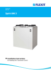
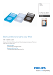
Instruction Manual
Instruction Manual
Ram Unit Outfits
• SR20 – Ø80mm Single Post
• DR20/30/60 – Ø80mm Dual Post
• DR205 – Ø80mm Dual Post
• DRX205 – Ø160mm Dual Post
N:\Engineering\MANUALS\Ram Units\Ram Unit Outfits R1.7.docx
1 of 40
Issue 1.7
Instruction Manual
29/04/2014
N:\Engineering\MANUALS\Ram Units\Ram Unit Outfits R1.7.docx
2 of 40
Issue 1.7
Instruction Manual
Table of Contents
Warnings
Specification
General Description
Model Selection
SR20
Installation
Operation Instructions
Setting up Ram Trip Valve
Setting Up Ram Pressure
Lowering Ram Onto Material
Rising Ram From Drum
Parts List
Cart Assembly Drawing
Ram Assembly Drawing
DR20/30/60
Installation
Operation Instructions
Setting up Ram Trip Valve
Setting Up Ram Pressure
Lowering Ram Onto Material
Rising Ram From Drum
Parts List
Ram Assembly Drawings
DR205 / DR205X
Installation
Operation Instructions
Setting up Ram Trip Valve
Setting Up Ram Pressure
Lowering Ram Onto Material
Rising Ram From Drum
Parts List
Ram Assembly Drawings
………
………
………
………
………
………
………
………
………
………
………
………
………
………
………
………
………
………
………
………
………
………
………
………
………
………
………
………
………
………
………
………
N:\Engineering\MANUALS\Ram Units\Ram Unit Outfits R1.7.docx
4
6
7
8
11
11
12
12
12
13
13
14
15
16
18
18
19
19
19
20
20
21
22
24
24
25
25
25
26
26
27
29
104097 Ram Control Box
104098 Air Regulator Unit
104105 Trip Rod Assembly
Ram Plate Options
20L / 5G
Ram Plate Assembly Drawing
30L / 7.5G
Ram Plate Assembly Drawing
60L / 15 G
Ram Plate Assembly Drawing
Accessories
Spare Parts
3 of 40
Issue 1.7
………
………
………
………
………
………
………
………
………
………
………
………
31
32
33
34
34
34
35
35
36
36
37
38
Instruction Manual
N:\Engineering\MANUALS\Ram Units\Ram Unit Outfits R1.7.docx
4 of 40
Issue 1.7
Instruction Manual
N:\Engineering\MANUALS\Ram Units\Ram Unit Outfits R1.7.docx
5 of 40
Issue 1.7
Instruction Manual
Specification
Feature
Down thrust
at 6 bar air
pressure
Remarks
SR20
DR20/30/60
DR205
DRX205 #
2.5 KN / 562 lbf
5 KN / 1124 lbf
5 KN / 1124 lbf
22.6 KN / 5080 lbf
Maximum Working Air Pressure
7 Bar / 101 psi
Air Inlet
1/2" BSP F
Air Quality
ISO 8573-1
Class 5/5/4
Ram Stroke
Unit Height Fully
Extended
Wiper Ring
Material
Weight
without
Pump
Extreme Duty
Dirt
Water
Oil
40 Microns
+7°C @ 7 Bar
25mg/m³
410 mm / 16"
688 mm / 27"
SR20
DR20/30/60
DR205
DRX205
SR20
DR20/30/60
DR205
DRX205
SR20
DR20/30/60
DR205
DRX205
SR20
DR20/30/60
DR205
DRX205
960 mm / 37.8"
1242 mm / 49"
1750 mm / 69"
2550 mm / 100"
EPDM / PU
EDPM
55 Kg / 121 lbs
130 Kg / 286 lbs
212 kg / 466 lbs
# = Denotes call for availability
N:\Engineering\MANUALS\Ram Units\Ram Unit Outfits R1.7.docx
6 of 40
Issue 1.7
Instruction Manual
General Description
Ram Unit Outfits are designed to ensure correct ‘priming’ of the pump fluid section
inlet and to prevent ‘cavitation’ when high viscosity materials are pumped. The
Ram units will accommodate industry standard barrels from 20-205L.
The outfits comprise of Ram Unit, Pump and Follower plate assembly.
The Follower plate is designed to accept both chop check or ball check pumps
The Ram plate has two seals, which accurately fit the inside of the barrel, as
material is used the ram plate descends, cleaning the sides of the barrel, reducing
wastage to a minimum.
A pneumatic control box (see page 31) with necessary Ram control features
• Raise and lower the ram plate
• A ‘release valve to separate the ram from the empty container.
• Air pressure regulator to control Downforce pressure
• Pump Stop / Start
A height adjustable trip valve assembly (see page 32) is also included as standard
to stop the pump when the bottom of the container is reached.
The pump air regulator unit (see page 33) is supplied with hose connection to the
air motor.
An option is available to provide automatic ‘changeover’ when using two Ram
Units in Duty / Standby mode.
N:\Engineering\MANUALS\Ram Units\Ram Unit Outfits R1.7.docx
7 of 40
Issue 1.7
Instruction Manual
Model Selection
Ram Unit Outfit Selection Guide
TYPICAL EXAMPLE:
• DR205E – MX86023PU – SMX
TABLE 1
TABLE 2
CODE
DESCRIPTION
CODE
SR
DR
DRX
Single Post Ram (Ø80mm)
Dual Post Ram (Ø80mm)
Dual Post Ram Extreme Duty (Ø160mm)
20
30
60
205
DESCRIPTION
20L / 5 Gallon Drum
30L / 7.5 Gallon Drum
60L / 15 Gallon Drum
205L / 55 Gallon Drum
Table 1 Ref.
SR DR DRX
TABLE 3
CODE
E
P
DESCRIPTION
EPDM
Polyurethane
N:\Engineering\MANUALS\Ram Units\Ram Unit Outfits R1.7.docx
8 of 40
Table 2 Ref.
20
30
60 205
Issue 1.7
Instruction Manual
TABLE 4 - Chop Check Pumps
CODE
68
115
200
420
860
DESCRIPTION
SR Ram
68 cc/cycle
115 cc/cycle
200 cc/cycle
420 cc/cycle
860 cc/cycle
DR / DRX Rams
20
20
30
60
205
TABLE 4 – Ball Check Pumps
CODE
122
190
220
440
880
DESCRIPTION
122 cc/cycle
190 cc/cycle
220 cc/cycle
440 cc/cycle
880 cc/cycle
SR Ram
DR / DRX Rams
20
20
30
60
205
TABLE 5 - Chop Check Pumps
CODE
05
12
15
18
23
24
30
33
39
43
46
66
68
DESCRIPTION
5:1 Pump Ratio
12:1 Pump Ratio
15:1 Pump Ratio
18:1 Pump Ratio
23:1 Pump Ratio
24:1 Pump Ratio
30:1 Pump Ratio
33:1 Pump Ratio
39:1 Pump Ratio
43:1 Pump Ratio
46:1 Pump Ratio
66:1 Pump Ratio
68:1 Pump Ratio
N:\Engineering\MANUALS\Ram Units\Ram Unit Outfits R1.7.docx
Table 4 Ref.
68
115 200 420 860
9 of 40
Issue 1.7
Instruction Manual
TABLE 5 – Ball Check Pumps
CODE
DESCRIPTION
Table 4 Ref.
112 190 220 440 880
15
18
22
23
30
35
41
46
60
15:1 Pump Ratio
18:1 Pump Ratio
22:1 Pump Ratio
23:1 Pump Ratio
30:1 Pump Ratio
35:1 Pump Ratio
41:1 Pump Ratio
46:1 Pump Ratio
60:1 Pump Ratio
TABLE 6
CODE
PU
DESCRIPTION
PTFE & UHMWPE
TABLE 7
Table 4 Ref.
CODE
DESCRIPTION
Chop Check Pumps
Ball Check Pumps
68 115 200 420 860 122 190 220 440 880
C
S
Nitrided Carbon Steel
Ceramic Coated Stainless Steel
TABLE 8
Table 4 Ref.
CODE
DESCRIPTION
Chop Check Pumps
2 Ball Pumps
68 115 200 420 860 112 190 220 440 880
B
X
Ram Mount Ball Pump
Ram Mount Chop Check Pump
N:\Engineering\MANUALS\Ram Units\Ram Unit Outfits R1.7.docx
10 of 40
Issue 1.7
Instruction Manual
SR20 - Models
104110 - Installation
The ram plate base should be mounted on a stable and level floor.
The standard ram plate has 4off - holes Ø 16 mm to enable the base to be
securely fixed to the floor. Suitable floor fixing ‘rawbolts’ should be used which are
designed to suit the floor material.
Base plate = 500mm x 350mm. Mounting holes = 440mm x 290mm
A compressed air supply is connected to the 1/2” BSP F connection to control the
lift and lowering of the air cylinders and supply the pump.
N:\Engineering\MANUALS\Ram Units\Ram Unit Outfits R1.7.docx
11 of 40
Issue 1.7
Instruction Manual
Operation Instructions
Setting up ram trip valve
1. Make sure that the air to the pump is turned off by fully unwinding the regulator
on 104098.
2. Press the on (green) button on 104098. This indicator should now be green.
3. Place an empty drum under the ram plate. With the ram pressure set at 2 Bar
lower the ram into the drum until it has made contact with the bottom of the
drum. When the valve is tripped the indicator will switch to red (meaning pump
off).
4. Set the trip valve so that it has just tripped, by between 5 – 10mm. Test this a
number of times to make sure that the valve trips before the ram plate contacts
the bottom of the drum.
5. If different drums are to be used then checks should be made to make sure
that the valve is operated.
Setting up ram force for different materials
1.
2.
3.
4.
5.
Place a fresh drum of material underneath the ram plate.
Open the primer screw assembly (193754).
Set the ram force to 2 Bar.
Select the Up / Stop / Down controller to Down.
A slight delay will occur before the ram starts to move. This is to allow air to
exhaust from the ‘up’ side of the cylinder.
6. Check that the ram is going down squarely into the drum.
7. As the ram plate goes into the drum, air will be pushed out of the vent.
8. When material starts to come out of the vent, close the primer screw assembly.
9. Operate pump and system under normal operating conditions. At all times
checking the pump for cavitation. On very thick, non-flowing materials
pressures up to 5 Bar may be required, in order to prime the pump correctly.
However high ram pressures must not be used on light free-flowing materials
as leaks around the ram seals could develop.
10. When the air pressure is set use the “Raising the ram from a drum” procedure,
and remove drum from the unit.
11. It is now time to set the speed of the “Up and Down” motion of the ram unit.
12. To adjust the speed of the “Up” motion screw in restrictor 194232 all the way
then back out while testing up speed until desired speed is achieved.
13. Remove the cover from the 104097 control box mounted on the ram unit
leaving the hoses connected. Operate the “up / down” valve and at the same
time screw in or out the control valve (silencer / speed controller).
14. Do not use the pressure regulator to control the speed of the unit, as it will give
an uneven movement.
N:\Engineering\MANUALS\Ram Units\Ram Unit Outfits R1.7.docx
12 of 40
Issue 1.7
Instruction Manual
Operation
Lowering the ram onto material
1.
2.
3.
4.
5.
6.
7.
8.
9.
Place a fresh drum of material underneath the ram plate.
Open the primer screw assembly.
Select the Up / Stop / Down controller to down.
Make sure that the ram force is to the correct pressure. ( see Setting up ram
pressure )
A slight delay will occur before the ram starts to move. This is to allow air to
exhaust from the ‘up’ side of the cylinder.
Check that the ram is going down squarely into the drum.
As the ram plate goes into the drum, air will be pushed out of the vent.
When material starts to come out of the vent, close the primer screw assembly.
The ram is now ready to use.
Raising the ram from a drum
1. Make sure that the pump is turned off, air pressure relieved and pump
pressure also relieved.
2. Select the Up / Stop / Down controller to up.
3. As the ram starts to move inject small busts of compressed air by pressing the
Drum Release button mounted on the side of the unit. This will slowly push the
drum off the ram.
4. Be very carefully not to inject too much air, as air can escape between the ram
plate seal and the drum. This is not dangerous but can make an unnecessary
mess that requires cleaning.
N:\Engineering\MANUALS\Ram Units\Ram Unit Outfits R1.7.docx
13 of 40
Issue 1.7
Instruction Manual
SR20 Outfit Assemblies
Parts List - SR20 Ram Unit Outfits
Item
Part No.
Description
1
104110
20L RAM ASSEMBLY
1
2
193916
20L RAM PLATE ASSEMBLY – PU
1
2
193994
20L RAM PLATE ASSEMBLY - EPDM
1
3
MX……
PUMP ASSEMBLY – SEE SELECTION TABLE
1
4
193997
CONNECTION KIT – NOT SHOWN
1
MX68 PUMPS
5
194258
CONNECTION KIT – NOT SHOWN
1
MX11543, MX12241
6
194259
CONNECTION KIT – NOT SHOWN
1
MX11568
N:\Engineering\MANUALS\Ram Units\Ram Unit Outfits R1.7.docx
14 of 40
Qty.
Remarks
Issue 1.7
Instruction Manual
Cart Mounted Ram Assembly Drawing
Parts List - Cart Mounted SR20 Ram Unit Outfits
Item
Part No.
1
SR20x-MX…
2
104128
Description
Qty.
20L RAM UNIT OUTFIT
1
CART KIT
1
N:\Engineering\MANUALS\Ram Units\Ram Unit Outfits R1.7.docx
15 of 40
Remarks
Issue 1.7
Instruction Manual
Ram Unit Parts List
Parts List - 104110 Ram Unit
Item
Part No.
1
0115-010211
2
Description
Qty.
Remarks
M6 NYLOCK NUT
2
104097
RAM CONTROL BOX
1
3
104098
RAM AIR REG SETUP
1
4
104107
20L RAM ASSEMBLY
1
5
163952
M6 x 20 SOCKET HD CAP SCREW
2
6
165129
M6 WASHER
4
7
165134
M8 WASHER
2
8
165139
M20 SPRING WASHER
1
9
177040
M20 DOME NUT
1
10
177041
M4 x 45 SOCKET HD CAP SCREW
2
11
177054
M20 PLAIN WASHER
1
12
177056
M8 x 16 HEX HEAD SCREW
2
13
192799
VENT PLUG
1
14
193790
TRIP VALVE BRACKET
1
15
193863
BRACKET MACHINING
1
16
193907
TRIP ROD 3/2 VALVE
1
17
193908
1/8" Ø4 PUSH IN ELBOW
2
18
193943
1/4" Ø6 PUSH IN ELBOW
1
19
193966
Ø6 1/4" SINGLE BANJO RING
1
20
194232
1/4" FLOW RESTRICTOR
1
21
DVX-27
M4 x 25 CAP HEAD SCREW
2
22
DVX-30
M4 NYLOC NUT
4
23
DVX-31
M4 WASHER
6
24
170244
Ø6 x 4 PU HOSE - BLACK
2m
NOT SHOWN
25
170245
Ø4 x 2.5 PU HOSE - BLACK
2m
NOT SHOWN
N:\Engineering\MANUALS\Ram Units\Ram Unit Outfits R1.7.docx
16 of 40
.
Issue 1.7
Instruction Manual
Ram Assembly Drawing
N:\Engineering\MANUALS\Ram Units\Ram Unit Outfits R1.7.docx
17 of 40
Issue 1.7
Instruction Manual
DR20/30/60 – Models
104102 - Installation
The ram plate base should be mounted on a stable and level floor.
The standard ram plate has 4off - holes Ø 15 mm to enable the base to be
securely fixed to the floor. Suitable floor fixing ‘rawbolts’ should be used which are
designed to suit the floor material.
Base plate = 710mm x 460mm. Mounting holes = 640mm x 390mm
A compressed air supply is connected to the 1/2” BSP F connection to control the
lift and lowering of the air cylinders and supply the pump.
N:\Engineering\MANUALS\Ram Units\Ram Unit Outfits R1.7.docx
18 of 40
Issue 1.7
Instruction Manual
Operation Instructions
Setting up ram trip valve
1. Make sure that the air to the pump is turned off by fully unwinding the regulator
on 104098.
2. Press the on (green) button on 104098. This indicator should now be green.
3. Place an empty drum under the ram plate. With the ram pressure set at 2 Bar
lower the ram into the drum until it has made contact with the bottom of the
drum. When the valve is tripped the indicator will switch to red (meaning pump
off).
4. Set the trip valve so that it has just tripped, by between 5 – 10mm. Test this a
number of times to make sure that the valve trips before the ram plate contacts
the bottom of the drum.
5. If different drums are to be used then checks should be made to make sure
that the valve is operated.
Setting up ram force for different materials
1.
2.
3.
4.
5.
Place a fresh drum of material underneath the ram plate.
Open the ram plate priming screw assembly (193754).
Set the ram force to 2 Bar.
Select the Up / Stop / Down controller to Down.
A slight delay will occur before the ram starts to move. This is to allow air to
exhaust from the ‘up’ side of the cylinder.
6. Check that the ram is going down squarely into the drum.
7. As the ram plate goes into the drum, air will be pushed out of the vent.
8. When material starts to come out of the vent, close the primer screw assembly.
9. Operate pump and system under normal operating conditions. At all times
checking the pump for cavitation. On very thick, non-flowing materials
pressures up to 5 Bar may be required, in order to prime the pump correctly.
However high ram pressures must not be used on light free-flowing materials
as leaks around the ram seals could develop.
10. When the air pressure is set use the “Raising the ram from a drum” procedure,
and remove drum from the unit.
11. It is now time to set the speed of the “Up and Down” motion of the ram unit.
12. Remove the cover from the 104097 control box mounted on the ram unit
leaving the hoses connected. Operate the “up / down” valve and at the same
time screw in or out he control valve (silencer / speed controller). The motion
needs to slow enough so that removing an empty drum can be one smooth
operation, about 1 full stroke in 30 seconds.
13. Do not use the pressure regulator to control the speed of the unit, as it will give
an uneven movement.
N:\Engineering\MANUALS\Ram Units\Ram Unit Outfits R1.7.docx
19 of 40
Issue 1.7
Instruction Manual
Operation
Lowering the ram onto material
1.
2.
3.
4.
5.
6.
7.
8.
9.
Place a fresh drum of material underneath the ram plate.
Open the ram primer screw assembly.
Select the Up / Stop / Down controller to down.
Make sure that the ram force is to the correct pressure. ( see Setting up ram
pressure )
A slight delay will occur before the ram starts to move. This is to allow air to
exhaust from the ‘up’ side of the cylinders.
Check that the ram is going down squarely into the drum.
As the ram plate goes into the drum, air will be pushed out of the vent.
When material starts to come out of the vent, close the primer screw assembly.
The ram is now ready to use.
Raising the ram from a drum
1. Make sure that the pump is turned off, air pressure relieved and pump
pressure also relieved.
2. Select the Up / Stop / Down controller to up.
3. As the ram starts to move inject small busts of compressed air by pressing the
Drum Release button mounted on the side of the unit. This will slowly push the
drum off the ram.
4. Be very carefully not to inject too much air, as air can escape between the ram
plate seal and the drum. This is not dangerous but can make an unnecessary
mess that requires cleaning.
N:\Engineering\MANUALS\Ram Units\Ram Unit Outfits R1.7.docx
20 of 40
Issue 1.7
Instruction Manual
DR20/30/60 Outfit Assemblies
Parts List - DR20/30/60 Ram Unit Outfits
Item
Part No.
Description
1
104102
60L RAM ASSEMBLY
1
2
193916
20L RAM PLATE ASSEMBLY – PU
1
2
193994
20L RAM PLATE ASSEMBLY - EPDM
1
2
193917
30L RAM PLATE ASSEMBLY – PU
1
2
193995
30L RAM PLATE ASSEMBLY - EPDM
1
2
193918
60L RAM PLATE ASSEMBLY – PU
1
2
193996
60L RAM PLATE ASSEMBLY - EPDM
1
3
MX……
PUMP ASSEMBLY – SEE SELECTION TABLE
1
4
193998
CONNECTION KIT – NOT SHOWN
1
MX68 PUMPS
5
193999
CONNECTION KIT – NOT SHOWN
1
MX11568,
190/200/220 MODELS
6
194268
CONNECTION KIT – NOT SHOWN
1
MX11543, MX12241
7
193737
MOUNTING PLATE
1
MX11568,
190/200/220 MODELS
8
194005
MOUNTING PLATE ASSEMBLY
1
68/115/122 MODELS
9
194265
MOUNTING PLATE ASSEMBLY
1
MX20024, MX22023
N:\Engineering\MANUALS\Ram Units\Ram Unit Outfits R1.7.docx
21 of 40
Qty.
Remarks
Issue 1.7
Instruction Manual
Ram Unit Parts Lists
Parts List - 104102 Ram Unit
Item
Part No.
Description
1
104097
RAM CONTROL BOX
1
2
104098
RAM AIR REG SETUP
1
3
104104
60L BARE RAM
1
4
104105
TRIP ROD ASSEMBLY
1
5
165139
M20 SPRING WASHER
2
6
177040
M20 DOME NUT
2
7
177041
M4 x 45 SOCKET HD CAP SCREW
4
8
193943
¼” Ø6 PUSH IN ELBOW
2
9
DVX-30
M4 NYLOC NUT
4
10
DVX-31
M4 WASHER
4
11
170244
Ø6 x 4 PU HOSE – BLACK
2m
12
170245
Ø4 x 2.5 PU HOSE - BLACK
2m
N:\Engineering\MANUALS\Ram Units\Ram Unit Outfits R1.7.docx
22 of 40
Qty.
Remarks
Issue 1.7
Instruction Manual
Assembly Drawing
N:\Engineering\MANUALS\Ram Units\Ram Unit Outfits R1.7.docx
23 of 40
Issue 1.7
Instruction Manual
DR205 & DRX205 – Models
104094 - Installation
The ram plate base should be mounted on a stable and level floor.
The standard ram plate has 4off - holes Ø 15 mm to enable the base to be
securely fixed to the floor. Suitable floor fixing ‘rawbolts’ should be used which are
designed to suit the floor material.
Base plate = 915mm x 600mm. Mounting holes = 840mm x 520mm
A compressed air supply is connected to the 1/2” BSP F connection to control the
lift and lowering of the air cylinders and supply the pump.
N:\Engineering\MANUALS\Ram Units\Ram Unit Outfits R1.7.docx
24 of 40
Issue 1.7
Instruction Manual
Operation Instructions
Setting up ram trip valve
1. Make sure that the air to the pump is turned off by fully unwinding the regulator
on 104098.
2. Press the on (green) button on 104098. This indicator should now be green.
3. Place an empty drum under the ram plate. With the ram pressure set at 2 Bar
lower the ram into the drum until it has made contact with the bottom of the
drum. When the valve is tripped the indicator will switch to red (meaning pump
off).
4. Set the trip valve so that it has just tripped, by between 5 – 10mm. Test this a
number of times to make sure that the valve trips before the ram plate contacts
the bottom of the drum.
5. If different drums are to be used then checks should be made to make sure
that the valve is operated.
Setting up ram force for different materials
1.
2.
3.
4.
5.
Place a fresh drum of material underneath the ram plate.
Open the ram plate venting ball valve.
Set the ram force to 2 Bar.
Select the Up / Stop / Down controller to Down.
A slight delay will occur before the ram starts to move. This is to allow air to
exhaust from the ‘up’ side of the cylinders.
6. Check that the ram is going down squarely into the drum.
7. As the ram plate goes into the drum, air will be pushed out of the ball valve
vent.
8. When material starts to come out of the vent, close the ball valve.
9. Operate pump and system under normal operating conditions. At all times
checking the pump for cavitation. On very thick, non-flowing materials
pressures up to 5 Bar may be required, in order to prime the pump correctly.
However high ram pressures must not be used on light free-flowing materials
as leaks around the ram seals could develop.
10. When the air pressure is set use the “Raising the ram from a drum” procedure,
and remove drum from the unit.
11. It is now time to set the speed of the “Up and Down” motion of the ram unit.
12. Remove the cover from the 104097 control box mounted on the ram unit
leaving the hoses connected. Operate the “up / down” valve and at the same
time screw in or out he control valve (silencer / speed controller). The motion
needs to slow enough so that removing an empty drum can be one smooth
operation, about 1 full stroke in 30 seconds.
13. Do not use the pressure regulator to control the speed of the unit, as it will give
an uneven movement.
N:\Engineering\MANUALS\Ram Units\Ram Unit Outfits R1.7.docx
25 of 40
Issue 1.7
Instruction Manual
Operation
Lowering the ram onto material
1.
2.
3.
4.
5.
6.
7.
8.
9.
Place a fresh drum of material underneath the ram plate.
Open the ram plate venting ball valve.
Select the Up / Stop / Down controller to down.
Make sure that the ram force is to the correct pressure. ( see Setting up ram
pressure )
A slight delay will occur before the ram starts to move. This is to allow air to
exhaust from the ‘up’ side of the cylinders.
Check that the ram is going down squarely into the drum.
As the ram plate goes into the drum, air will be pushed out of the vent ball
valve.
When material starts to come out of the vent, close the ball valve.
The ram is now ready to use.
Raising the ram from a drum
1. Make sure that the pump is turned off, air pressure relieved and pump
pressure also relieved.
2. Select the Up / Stop / Down controller to up.
3. As the ram starts to move inject small busts of compressed air by pressing the
Drum Release button mounted on the side of the unit. This will slowly push the
drum off the ram.
4. Be very carefully not to inject too much air, as air can escape between the ram
plate seal and the drum. This is not dangerous but can make an unnecessary
mess that requires cleaning.
N:\Engineering\MANUALS\Ram Units\Ram Unit Outfits R1.7.docx
26 of 40
Issue 1.7
Instruction Manual
DR205 Outfit Assemblies
Parts List - DR205 Ram Unit Outfits
Item
Part No.
Description
1
104094
205L RAM ASSEMBLY
1
2
MX……
PUMP ASSEMBLY – SEE SELECTION TABLE
1
3
194264
CONNECTION KIT – NOT SHOWN
1
68/115/122 MODELS
4
5
6
194000
194001
194263
CONNECTION KIT – NOT SHOWN
CONNECTION KIT – NOT SHOWN
CONNECTION KIT – NOT SHOWN
1
1
1
190/200/220 MODELS
7
194253
CONNECTION KIT – NOT SHOWN
1
MX11568
8
194257
CONNECTION KIT – NOT SHOWN
1
MX20024 / MX22023
N:\Engineering\MANUALS\Ram Units\Ram Unit Outfits R1.7.docx
27 of 40
Qty.
Remarks
420/440/860/880
MX11543 / MX12241
Issue 1.7
Instruction Manual
N:\Engineering\MANUALS\Ram Units\Ram Unit Outfits R1.7.docx
28 of 40
Issue 1.7
Instruction Manual
Ram Unit Parts Lists
Parts List - 104094 Ram Unit
Item
Part No.
Description
1
104097
RAM CONTROL BOX
1
2
104098
RAM AIR REG UNIT
1
3
104103
205L BARE RAM UNIT
1
4
104105
TRIP ROD ASSEMBLY
1
5
165139
M20 SPRING WASHER - PLATED
2
6
177034
M20 HEX NUT - PLATED
1
7
177035
M20 STUD CONNECTOR - PLATED
1
8
177041
M4 x 45 SOCKET HD CAP SCREW - PLATED
4
9
193765
SUPPORT BAR
1
10
193768
1/4" NON RETURN VALVE
1
11
193769
1/4" - Ø6 PUSH IN STRAIGHT - PLATED BRASS
1
12
193943
1/4" Ø6 PUSH IN ELBOW - PLATED BRASS
2
13
193944
1/2" PLATED BRASS BALL VALVE
1
14
193945
1/2" BSPT - 1/2" BSPT NIPPLE - PLATED BRASS
1
15
193946
1/2" MALE - 1/2" FEMALE ELBOW
1
16
0115-010682
3/8" MALE - 1/4" MALE NIPPLE
1
17
DVX-30
M4 NYLOC NUT
4
18
DVX-31
M4 WASHER
8
19
170244
Ø6 x 4 PU HOSE - BLACK
3m
NOT SHOWN
20
170245
Ø4 x 2.5 PU HOSE - BLACK
2m
NOT SHOWN
N:\Engineering\MANUALS\Ram Units\Ram Unit Outfits R1.7.docx
29 of 40
Qty.
Remarks
Issue 1.7
Instruction Manual
Assembly Drawing
N:\Engineering\MANUALS\Ram Units\Ram Unit Outfits R1.7.docx
30 of 40
Issue 1.7
Instruction Manual
104097 Ram Control Box Details
N:\Engineering\MANUALS\Ram Units\Ram Unit Outfits R1.7.docx
31 of 40
Issue 1.7
Instruction Manual
104098 Air Regulator Unit
N:\Engineering\MANUALS\Ram Units\Ram Unit Outfits R1.7.docx
32 of 40
Issue 1.7
Instruction Manual
Parts List - 104105 Trip Rod Assembly
Item
Part No.
1
2
3
4
5
6
7
8
9
10
11
12
13
14
0115-010211
163952
165129
165546
177031
192799
193902
193905
193906
193907
193908
DVX-27
DVX-30
DVX-31
Description
M6 NYLOC
M6 x 20 CAP HD SCREW
M6 WASHER
M6 x 40 CAP HD SCREW
M6 x 16 BUTTON HEAD SCREW
VENT PLUG
TRIP ROD ASSEMBLY
TRIP ROD CLAMP
VALVE BRACKET
TRIP ROD 3/2 VALVE
1/8" Ø4 PUSH IN ELBOW
M4x25 CAP HEAD SCREW
M4 NYLOC NUT
M4 WASHER
Qty.
Remarks
2
2
2
2
2
1
1
1
1
1
2
2
2
4
# - Recommended spares for 104105
N:\Engineering\MANUALS\Ram Units\Ram Unit Outfits R1.7.docx
33 of 40
Issue 1.7
#
Instruction Manual
Parts List - 193994 / 193916 Ram Plate 20L / 5G
Item
Part No.
Description
1
165123
Ø10 SPRING WASHER (STST)
8
2
165135
M10 PLAIN WASHER (ST ST)
8
3
177005
M10 HEX NUT
8
4
193749
60L RAM PLATE MACHINING
1
5
193754
PRIMER SCREW ASSEMBLY
1
6
193758
LOWER CLAMP RING ASSEMBLY
1
7
193761
20L SEAL CLAMP RING
1
8
193768
1/4" NON RETURN VALVE
1
9
193769
1/4" - Ø6 PUSH IN STRAIGHT - PLATED BRASS
1
10
193991
Ø300 SEAL - EDPM
2
193994
10
193913
Ø300 SEAL - PU
2
193916
11
193948
1/4" MALE - 1/4" MALE NIPPLE - PLATED BRASS
1
N:\Engineering\MANUALS\Ram Units\Ram Unit Outfits R1.7.docx
34 of 40
Qty.
Issue 1.7
Remarks
Instruction Manual
Parts List - 193917 / 193995 Ram Plate 30L / 7.5G
Item
Part No.
Description
1
165123
Ø10 SPRING WASHER
8
2
165135
M10 PLAIN WASHER
8
3
177005
M10 HEX NUT
8
4
193749
60L RAM PLATE MACHINING
1
5
193754
PRIMER SCREW ASSEMBLY
1
6
193758
LOWER CLAMP RING ASSEMBLY
1
7
193760
30L SEAL CLAMP RING
1
8
193768
1/4" NON RETURN VALVE
1
9
193769
1/4" - Ø6 PUSH IN STRAIGHT
1
10
193992
Ø330 SEAL - EDPM
2
193995
10
193914
Ø330 SEAL - PU
2
193917
11
193948
1/4" MALE - 1/4" MALE NIPPLE
1
N:\Engineering\MANUALS\Ram Units\Ram Unit Outfits R1.7.docx
35 of 40
Qty.
Issue 1.7
Remarks
Instruction Manual
Parts List - 193918 / 193996 Ram Plate 60L / 15G
Item
Part No.
Description
1
165123
Ø10 SPRING WASHER
8
2
165135
M10 PLAIN WASHER
8
3
177005
M10 HEX NUT
8
4
193749
60L RAM PLATE MACHINING
1
5
193754
PRIMER SCREW ASSEMBLY
1
6
193758
LOWER CLAMP RING ASSEMBLY
1
7
193757
60L SEAL CLAMP RING
1
8
193768
1/4" NON RETURN VALVE
1
9
193769
1/4" - Ø6 PUSH IN STRAIGHT
1
10
193993
Ø380 SEAL - EDPM
2
193996
10
193915
Ø380 SEAL - PU
2
193918
11
193948
1/4" MALE - 1/4" MALE NIPPLE
1
N:\Engineering\MANUALS\Ram Units\Ram Unit Outfits R1.7.docx
36 of 40
Qty.
Issue 1.7
Remarks
Instruction Manual
Accessories
Item
Part No.
104099
1
2
0110-009130
Description
Remarks
Auto Change Over Panel
To Automatically change over to a
Standby Ram Unit when the Duty
Ram Unit is empty (Bottom Position)
High Pressure Filter (100
Mesh)
0110-009131 – 50 Mesh
0110-009133 – 150 Mesh
0110-009134 – 200 Mesh
0114-014917 – 30 Mesh
0114-014886 – 50 Mesh
0114-014884 – 70 Mesh
0114-014883 – 100 Mesh
0114-014882 – 150 Mesh
0114-014881 – 200 Mesh
High Pressure Filter (100
Mesh)
(500 Bar Max.)
3
0114-011760
4
0115-010672
Dump Valve Kit
½” NPSM F Swivel – ¼” BSP/NPS M
5
0114-016099
Pump Lubrication
Water Based – 0.25L
6
0114-016100
Pump Lubrication
Solvent Based – 0.25L
7
0114-014871
Pump Lubrication
Water Based – 0.5L
8
0114-009433
Pump Lubrication
9
107866
Solvent Based – 0.5L
191833 – 200 Micron Element St St
191834 – 400 Micron Element St St
192523 – 600 Micron Element St St
192524 – 1200 Micron Element St St
10
107867
Filter Housing Carbon St
11
107876
Twin Filter Housing
Assembly St St
Filter Element to be Specified
Separately
12
107877
Twin Filter Housing
Assembly Carbon St
Filter Element to be Specified
Separately
Filter Housing St St
N:\Engineering\MANUALS\Ram Units\Ram Unit Outfits R1.7.docx
37 of 40
Issue 1.7
Instruction Manual
# Spare Parts For - (SR20) 104110 Ram Unit
Item
1
2
4
5
6
7
8
9
10
11
Part No.
193907
250700
193768
193769
193943
193908
170244
170245
193913
193991
Description
3/2 Trip Valve
Ram Cylinder Seal Kit
¼” Non Return Valve
¼” – Ø6 Push In Straight
¼” – Ø6 Push In Elbow
1/8” – Ø4 Push In Elbow
Ø6 x 4 PU Hose – Black
Ø4 x 2.5 PU Hose - Black
Ø300 Seal - PU
Ø300 Seal – EPDM
Qty
1
1
1
1
2
2
2m
2m
2
2
Remarks
# Spare Parts For – (DR20/30/60) 104102 Ram Unit
Item
1
2
3
4
5
6
7
8
9
10
11
12
13
Part No.
250700
193768
193769
193943
193908
170244
170245
193913
193991
193914
193992
193915
193993
Description
Ram Cylinder Seal Kit
¼” Non Return Valve
¼” – Ø6 Push In Straight
¼” – Ø6 Push In Elbow
1/8” – Ø4 Push In Elbow
Ø6 x 4 PU Hose – Black
Ø4 x 2.5 PU Hose - Black
Ø300 Seal – PU
Ø300 Seal – EPDM
Ø330 Seal – PU
Ø330 Seal – EPDM
Ø380 Seal – PU
Ø380 Seal – EPDM
N:\Engineering\MANUALS\Ram Units\Ram Unit Outfits R1.7.docx
38 of 40
Qty
2
1
1
2
2
2m
2m
2
2
2
2
2
2
Remarks
20L
20L
30L
30L
60L
60L
Issue 1.7
Instruction Manual
# Spare Parts For – (DR205) 104094 Ram Unit
Item
1
2
3
4
5
6
7
8
9
10
11
Part No.
207064
202522
181672
193768
193769
193943
193947
170244
170245
250700
181422
Description
Wiper ring
Strapping
Strap buckle
¼” Non Return Valve
¼” – Ø6 Push In Straight
¼” – Ø6 Push In Elbow
½” Male – ¼” Male Nipple
Ø6 x 4 PU Hose – Black
Ø4 x 2.5 PU Hose - Black
Ram Cylinder Seal Kit
Gasket
Qty
2
2
4
1
1
2
1
3m
2m
2
1
Remarks
# Spare Parts For - 104105 Trip Valve Kit
Item
1
Part No.
193907
Description
3/2 Trip Valve
N:\Engineering\MANUALS\Ram Units\Ram Unit Outfits R1.7.docx
Qty
1
39 of 40
Remarks
Issue 1.7
Instruction Manual
Justus-von-Liebig-Straße 31, 63128 Dietzenbach. DE
Tel. +49 (0) 6074 403 1 Fax. +49 (0) 607 403 300
General e-mail: [email protected]
Ringwood Road, Bournemouth, Dorset BH11 9LH. UK
Tel. +44 (0)1202 571 111 Fax. +44 (0)1202 573 488
General e-mail: [email protected]
163-171, Av. des Auréats, 26014 Valence cedex. FR
Téléphone : +33 (0) 4 75 75 27 53 Télécopie: +33 (0) 4 75 75 27 79
General e-mail: [email protected]
USA Canada Customer Service
195 Internationale Blvd.
Glendale Height,IL 60139
630-237-5000
Toll Free Customer Service and
Technical Support 800-992-4657
Toll Free Facsimile 800-246-5732
Binks registered office Finishing Brands Germany GmbH Justus-von-Liebig-Straße 31, 63128 Dietzenbach. Amtsgericht Offenbach HRB 43560
N:\Engineering\MANUALS\Ram Units\Ram Unit Outfits R1.7.docx
40 of 40
Issue 1.7