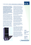
1
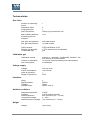
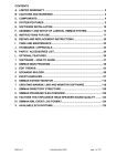
Translation of the original operating instructions Process gas analyzer INCA3011 Device type T181-01 Nov-2012 Union Instruments GmbH Zeppelinstrasse 42 76185 Karlsruhe Germany +49 (0)721-680381-0 +49 (0)721-680381-26 [email protected] http://www.union-instruments.com © 2012 This documentation is copyrighted. The engendered rights are retained, in particular the rights to translation, reprinting, taking pictures, radio transmission, reproduction by photomechanical or similar methods and storage in data processing systems, including excerpts. The right to technical changes is retained. Dimensions 3 Measuring range and accuracy– continuous3 measurement Components CH4 CO2 continuous continuous Unit Measuring precision T181 1 C2+ H2S H2S 4 H2S +μPulse discontinuous O2 O2 (chemical) (paramagnetic) continuous continuous H2 continuous discontinuous discontinuous Vol% ± 1% FS1 Vol% ± 1% FS 1 VOl% ± 1% FS 1 ppm ± 3 ppm ppm ± 60 ppm ppm ± 3 ppm (≤ 25 ppm) ± 15% MV2 > 25 ppm ppm ± 5 ppm (≤ 25 ppm) ± 15% MV2 > 25 ppm Vol% ± 1% FS 1 Vol% ± 1% FS 1 ppm ± 5% FS 1 100 100 15 – – – – 25 – – FS = Linearity error relative to full scale value MV = Linearity error relative to measured value 3 Only for one measuring point 2 H2S +μPulse discontinuous discontinuous Technical data Gas inlets Number of measuring points: Calibration inlets: Purge gas inlets: Gas connections: 1 Max. distance between measuring point an analyzer: 10 m Max. gas inlet pressure: Min. gas inlet pressure: 300 mbar relative 10 mbar relative Flame arrester: Relative gas humidity: Condensate trap: ATEX certification G IIC ≤ 70% (exempt from condensate) yes 2 1 Clamp ring connection 6 mm Calibration gas Calibration interval: Duration of calibration: Gas consumption: manual or automatic (configurable between one hour and up to several weeks) 10 minutes (recommended by the manufacturer) 5 l/calibration Voltage supply Voltage: Power consumption: Class of protection Degree of protection 100-240 V AC 100 VA max. I IP43 Interfaces Relay: Digital interface: Fieldbus: optional Relay: 3 RS232 Option Option, max. 8 Ambient conditions Ambient temperature: Humidity: Ambient pressure: Temperatur storage: Ambient pressure storage: 5-40°C 0-95% relative humidity 900-1250 hPa (0.9 – 1.2 bar) 0 – 60°C 700-1400 hPa (0.7-1.4 bar) Weight: up to 26 kg Weight 5 NOTE When using the INCA outside of normal ambient conditions, coordinate additional measures (air conditioning of the process analyzer, etc.) with Union Instruments GmbH! 6 Table of contents 1 EC Declaration of Conformity ....................................................................................... 9 2 Safety notes ................................................................................................................. 10 2.1 Warnings and symbols ............................................................................................... 10 2.2 Fundamentals of proper use ....................................................................................... 11 2.3 Personnel and qualifications ....................................................................................... 11 2.4 Safety notes ............................................................................................................... 12 2.4.1 General safety notes ................................................................................................ 12 2.4.2 Indications of special hazards .................................................................................. 12 2.5 Regular operator training ............................................................................................ 12 2.6 Workplace hazard analysis ......................................................................................... 13 3 Safety equipment......................................................................................................... 14 3.1 Master switch ............................................................................................................. 14 3.2 Safety equipment........................................................................................................ 14 3.2.1 Door - not electronically queried ............................................................................... 14 3.2.2 Ventilator monitoring ................................................................................................ 14 3.3 IDs and warnings ........................................................................................................ 15 4 Connections................................................................................................................. 16 4.1 Accessories ................................................................................................................ 17 5 Transport, setup and acceptance ............................................................................... 18 5.1 Transport .................................................................................................................... 18 5.2 Ambient conditions ..................................................................................................... 19 5.2.1 Ambient conditions for operation .............................................................................. 19 5.2.2 Storage conditions.................................................................................................... 19 5.3 Set up and connection ............................................................................................... 20 5.4 Setup site ................................................................................................................... 20 5.4.1 Wall attachment ....................................................................................................... 21 5.4.2 Process gas ............................................................................................................. 22 5.4.3 Electrical connection ................................................................................................ 23 5.4.4 Electrical interfaces .................................................................................................. 24 5.4.5 Operator safety precautions ..................................................................................... 27 5.5 Startup after setup ...................................................................................................... 27 5.6 Documentation ........................................................................................................... 27 6 Startup /turning on ...................................................................................................... 29 7 Description of the workplaces/operating elements .................................................. 31 7.1 Workplaces ............................................................................................................... 31 8 Operation ..................................................................................................................... 33 8.1 Description of Display ................................................................................................. 34 8.1.1 Using the membrane keypad ................................................................................... 34 8.1.2 Display area ............................................................................................................. 35 8.2 Available displays ....................................................................................................... 35 8.2.1 Menu structure ......................................................................................................... 36 8.2.2 Navigate with the arrow keys left ◄ and right ► ...................................................... 37 8.2.3 Navigation with arrow keys up ▲ and down ▼ ......................................................... 38 8.2.4 Navigation with ESC and MENU .............................................................................. 39 8.2.5 Measurement display ............................................................................................... 40 8.2.6 Measuring channel display ....................................................................................... 40 8.2.7 Saved measured values ........................................................................................... 41 7 8.2.8 Display in the warmup phase.................................................................................... 41 8.2.9 Select language........................................................................................................ 42 8.2.10 Password ................................................................................................................. 43 9 Decommissioning/shutting off ................................................................................... 45 10 Servicing ...................................................................................................................... 47 10.1 Preparations ............................................................................................................... 47 10.2 Servicing/inspection .................................................................................................... 48 11 Troubleshooting .......................................................................................................... 49 11.1 Preparations ............................................................................................................... 49 11.2 Changing fuses........................................................................................................... 50 11.3 Messages/malfunctions on the display........................................................................ 50 11.3.1 Display of messages/malfunctions............................................................................ 50 11.3.2 Visualizing the error list ............................................................................................ 50 11.3.3 Troubleshooting list .................................................................................................. 50 12 Service ......................................................................................................................... 51 13 Associated documents ............................................................................................... 53 14 Disposal ....................................................................................................................... 55 15 Spare parts................................................................................................................... 57 16 Annex ........................................................................................................................... 59 Index ................................................................................................................................... 59 Table of figures .................................................................................................................... 60 8 1 EC Declaration of Conformity Der Hersteller / The manufacturer Union Instruments GmbH Zeppelinstrasse 42 76185 Karlsruhe erklärt hiermit, dass folgend bezeichnete Produkte / hereby declares, that following named products: Produktbezeichnung: Product name Gasanalysator Gas Analyzer Gerätegruppe: device group INCA3051 INCA3051 konform sind mit den Anforderungen, die in der EG – Richtlinie festgelegt sind / are compliant with the requirements as defined in the EC directive: 2006/42/EG 2006/42/EC Maschinenrichtlinie Machinery directive 2004/108/EG 2004/108/EC Elektromagnetische Verträglichkeit Electromagnetic compatibility Angewandte harmonisierte Normen / Used harmonized standards: DIN EN 61010-1:2011 Sicherheitsbestimmungen für elektrische Mess-, Steuer-, Regel- und Laborgeräte - Teil 1: Allgemeine Anforderungen; Safety requirements for electrical equipment for measurement, control and laboratory use - Part 1: General requirements DIN EN ISO 12100:2011 Sicherheit von Maschinen- Allgemeine Gestaltungsleitsätze - Risikobeurteilung und Risikominderung Safety of machinery - General principles for design - Risk assessment and risk reduction DIN EN 61326-1:2006 Elektrische Mess-, Steuer-, Regel- und Laborgeräte - EMV-Anforderungen - Teil 1: Allgemeine Anforderungen Electrical equipment for measurement, control and laboratory use - EMC requirements - Part 1: General requirements Name des Dokumentationsbevollmächtigten: Name delegate of documentation Schlichter Adresse des Dokumentationsbevollmächtigten: address delegate of documentation siehe Adresse des Herstellers see address of manufacturer Bei einer nicht autorisierten Änderung des Gerätes verliert diese Erklärung ihre Gültigkeit. / Any unauthorized modification of the device results in invalidity of this declaration. 9 2 Safety notes 2.1 Warnings and symbols In the operating instructions, the following names and symbols are used for particularly important information: DANGER Immediate danger that can lead to serious physical injury or death. WARNING Potentially hazardous situations that can lead to serious injury or death. NOTE Potentially hazardous situations that can lead to minor physical injury. This can also be used for property damage. NOTE For information that can make it easier to handle the process gas analyzer or help prevent property damage. 10 2.2 Fundamentals of proper use The process gas analyzer serves to identify gases and their quality in biogas, crude biogas, lean gas and biomethane. Applications are biological process optimization during motor control, controlling preparation systems, analyzing biogas, landfill gas and gas from purification plants. The gas analyzer is not suitable for determining the workplace threshold or lower explosion limit. In the case of toxic and explosive gases, observe the safety instructions at the setup site. The process gas analyzer is permanently installed and is only intended for use in enclosed spaces with sufficient ventilation. Any use beyond this is considered improper. The manufacturer is not liable for the resulting damage; the associated risk is borne by the installer, fitter, operator or user. Only certified professionals may alter the process gas analyzer (mechanical, electrical or pneumatic modifications). WARNING Proper use includes following these operating instructions. In addition to the following safety notes, always follow the safety instructions of the linked system components. Additional equipment or accessories that are not installed, delivered or manufactured by UNION Instruments GmbH require the approval of UNION Instruments GmbH as the manufacturer! Otherwise the guarantee expires. 2.3 Personnel and qualifications Gas connections and work on the electrical equipment of the process gas analyzer may only be performed by a professional while observing safety regulations. 11 2.4 Safety notes 2.4.1 General safety notes WARNING The process gas analyzer may only be operated when all of the protective equipment is available and operable. Additional safety notes. before the corresponding chapters! 2.4.2 Indications of special hazards WARNING 2.5 After installation, all gas conducting parts must be checked for leaks according to national regulations. All repairs that require the protective covering to be opened may only be performed by trained personnel. Sensors can contain sulfuric acid. This may leak in case of improper use. Protect from contact with skin and eyes. Regular operator training NOTE Country-specific regulations about regular user training by the operator must be observed, in particular training on handling gases and electrical equipment. 12 2.6 Workplace hazard analysis NOTE Depending on the national regulations, the operator must perform a workplace hazard analysis, if applicable independent of the CE mark for this process gas analyzer. Technical developments can give rise to deviations from these operating instructions. If you desire additional information or if particular problems arise that are not fully addressed in this manual, please contact the following address: Union Instruments GmbH Zeppelinstrasse 42 76185 Karlsruhe Germany +49 (0)721-680381-0 +49 (0)721-680381-26 [email protected] http://www.union-instruments.com 13 3 Safety equipment 3.1 Master switch Fig. 3.1: 3.2 Master switch Safety equipment 3.2.1 Door - not electronically queried Door to the process gas analyzer. 3.2.2 Ventilator monitoring If the housing fan fails, the process gas analyzer is de-energized. The power supply and fan monitor controls still have power. 14 3.3 IDs and warnings Fig. 3.2: IDs and warnings 15 4 Connections 1 11 10 2 3 9 4 5 6 7 7 8 Fig. 4.1: Product description 1. Power supply cable lead-through 2. 3. 4. 5. 6. 7. Line leakage outlet Ambient air inlet Process gas outlet Process gas 1 Calibration gas 1 Purge gas 8. can be expanded depending on the design 9. Operating element 10. Cable lead-throughs 11. Fan NOTE Up to 4 process gas lines can be connected. With each additional connected process gas line, the connections for calibration and scavenging gas drop one connection lower. 16 4.1 Accessories WARNING Risk of injury/defective! The use of unreleased accessories can cause defects and be hazardous. In this case, the guarantee expires. The operator is then liable for any damage that may occur. Only use original accessories or accessories that have been approved by Union Instruments GmbH. 17 5 Transport, setup and acceptance NOTE Generally, the process gas analyzer is started up by Union Instruments GmbH or service technicians. If it is not transported, set up and started up by Union Instruments GmbH (for example in-house transportation and resale), coordinate the appropriate procedure with Union Instruments GmbH ( Chapter 12 Service). 5.1 Transport WARNING Possible injury from the process gas analyzer tipping over or falling from pallets and load carrying equipment. The process gas analyzer can weigh up to 60 kg including packaging. Two persons are needed to package and transport the analyzer. Check the load bearing capacity and condition of the slinging equipment and carefully attach it. Never stand under a suspended loads. NOTE In case of damage during transport from improper handling, the carrier should perform a damage report within seven days (railway, post office, freight forwarder). 18 5.2 Ambient conditions NOTE Ambient conditions during storage and set up. Observe the stipulated ambient conditions. Contact Union Instruments GmbH if the process gas analyzer has been stored for more than three months or needs to be operated or stored under ambient conditions other than those specified. 5.2.1 Ambient conditions for operation Ambient temperature: Humidity: Ambient pressure: 5-40°C 0-95% relative humidity 900-1250 hPa (0.9-1.2 bar) 5.2.2 Storage conditions Ambient temperature: Humidity: Ambient pressure: 0-60°C 0-95% relative humidity 700-1400 hPa (0.7-1.4 bar) 19 5.3 Set up and connection 5.4 Setup site The setup site for the process gas analyzer must satisfy the following conditions: Clean dry room (with the exception of INCA outdoor) No direct exposure to sun Protect from climate influences with a heater or air conditioning if necessary Insure a clean, sufficient amount of ambient air for undistorted measurements Ensure that the loadbearing capacity of the wall is sufficient WARNING Leaking process gas can pose a hazard and needs to be discharged by the operator into a safe environment. 20 5.4.1 Wall attachment The INCA is intended for wall installation. The wall holder is included in the delivery. The wall for installation needs to be sufficiently stable to bear the weight of the INCA. Attach the wall holder to the wall according to the sketch. Adjust the wall holder so that it is horizontal using slots (spaced 500 mm). Suspend the INCA from the holes. Fig. 5.1: Wall attachment 21 5.4.2 Process gas NOTE The connecting parts need to be clean and free of residue. Impurities can enter of the process gas analyzer and cause incorrect measurement and/or damage. The inlet pressure for the gas connections may not exceed the level on the instruction sticker on the process gas analyzer. Each connection needs to be carefully checked for leaks. If there are any leaks, the system will draw air, and the measurements will be incorrect. Do not use sealing compound to seal the gas connections. Sealing compound can distort measurements. Use PTFE pipe tape. Only use suitable pipes. Use a separate line to drain the condensate. NOTE The process gas must be free of condensate and dust for the process gas analyzer or gas preparation system (or a gas cooler). 22 5.4.3 Electrical connection DANGER Danger from electrical shock! Only a trained electrician may modify the electrical equipment of the process gas analyzer in accordance with the relevant guidelines. Parts of the opened process gas analyzer identified with an adjacent signal may still be live even when they master switch has been turned off. If necessary, disconnect the process gas analyzer from the power supply. 23 5.4.4 Electrical interfaces WARNING Untrained personnel starting the process gas analyzer may endanger people and equipment. Only trained service technicians may start up the analyzer. 3 1 2 Fig. 5.2: Electrical interfaces Item No. 24 Name 1 Relay Fig. 5.3 and 5.4! 2 Analog outputs (optional) 5.5 3 Profibus module (optional) 1 Fig. 5.3: Item No. 2 3 Relay I/O board Name Function 1 Relay K1 Operation 2 Relay K2 Failure (inverted) 3 Relay K3 OFF Fig. 5.4: Relay I/O board connection assignment left - middle: normally closed right - middle: normally opened NOTE Relay only operated with functional extra low voltage Do not connect to the power supply. 25 7 - 8 - 5 Fig. 5.5: Item No. - 3 - 6 - 4 - 1 - 2 - Analog output I/O board 1 Output 1 – signal/signal 4-20 mA 5 Function (2-channel device) Output 5 – signal/signal 4-20 mA - 1GND - 5GND 2 Output 2 – signal/signal 4-20 mA 6 Output 6 – signal/signal 4-20 mA - 2GND - 6GND 3 Output 3 – signal/signal 4-20 mA 7 Output 7 – signal/signal 4-20 mA - 3GND - 7 GND 4 Output 4 – signal/signal 4-20 mA 8 Output 8 – signal/signal 4-20 mA - 4GND - 8GND Function Item No. NOTE Current assignment depending on the configuration, see attached wiring diagram. 26 5.4.5 Operator safety precautions WARNING 5.5 The operator needs to provide suitable safety equipment for the process gas analyzer to reliably prevent individuals from being injured from gas leaks. Any leaking process gas needs to be diverted into a safe environment. Identify the exit for the diverted gas with a warning. Danger of stumbling from improperly laid supply lines. Run the supply lines appropriately. Startup after setup WARNING Untrained personnel starting the process gas analyzer may endanger people and equipment. Only trained service technicians may start up the analyzer. 5.6 Documentation NOTE Union Instruments GmbH recommends keeping a service manual and documenting all jobs and tests. 27 28 6 Startup /turning on NOTE To establish operational readiness, including of the linked system components, according to the operating instructions. NOTE The following table contains highly abbreviated steps for starting up after a long downtime. To turn on the process gas analyzer after a short downtime, a few steps can be eliminated: right column! Steps Startup Turning on X X Check if the ambient conditions meet the requirements ( Page 19, Chapter 5.2.1). Check if the process gas analyzer is securely fastened. Check if the device is suitable for process gas. X Check if the process gas is correct. X Check if gas connections are correct and tight. X X Check the water filter for condensate. X X Check if the calibration gas is correct. X X Turn on the operator energy and media supply. X X Check the voltage. X Open the manual shutoff valves. X X Turn on the master switch. X X Make sure the linked system components are ready to start. X X X If the process gas analyzer was only turned off temporarily, production can be restarted. 29 30 7 Description of the workplaces/operating elements NOTE This chapter only discusses elements relating to the use of the INCA by normal operators. 7.1 Workplaces 1 Fig. 7.1: Item No. 1 Workplaces Name Display Function/activity Display status. 31 32 8 Operation WARNING Danger of injury! Only use the process gas analyzer when all lines have been installed and checked for leaks according to national regulations. 33 8.1 Description of Display 8.1.1 Using the membrane keypad The software controls are operated using a membrane keypad. The displayed buttons can be selected by pressing the key. The menu structures are intentionally flat to enable quick access functions. NOTE Damage to the membrane keypad! The membrane keypad can be damaged if you use other objects to operate it beside your fingers. 1 2 3 MEASURING Channel : 07/22/2009 4 14:42:21 4:57 1/3 5 Fig. 8.1: Item No. Name Function Display the current sensor measurements. 4 Measurement display Measuring channel display Saved measured values Display 5 Menu keys Navigating the menu structure 1 2 3 34 Operating elements Display the current channel measurements. Switch between the last 10 saved mission values. Display values, times and measurement results 8.1.2 Display area 1 2 Fig. 8.2: Item No. 8.2 Display area Name Function 1 Top display area Display the status and channel information 2 Bottom display area Switch between various measured values with the arrow keys (▼▲►◄). Available displays NOTE The available structures and their function are described below. The way to the displays is indicated by the menu and function keys in the chapter headings. The controls are based on the structure shown below. 35 8.2.1 Menu structure NOTE Some of the menu items framed in red can be influenced after changing the measurement results. Main menu Settings Language Password Cal. purge gas (only available for certain device configurations) Send data Communication Parameter Gas cooler temperature (only available for analyzers with a gas cooler) EC cycle (only available for certain device configurations) Commands Changing channels (only available for analyzers with several measuring sites) System restart Delete message Cal. purge gas Cal. gas I Cal. gas II (not yet available) Cal. reset System Info System messages 36 8.2.2 Navigate with the arrow keys left ◄ and right ► ● The display indicates that the measuring status is active. ● Switch between the measurements by pressing the left ◄ and right ► keys. The asterisk ( ) indicates that a saved value is being displayed. The values are updated in the display depending on the measuring status. With continuous measurement, an asterisk is not displayed since the value is measured and updated continuously. 37 8.2.3 Navigation with arrow keys up ▲ and down ▼ NOTE To navigate with the arrow keys up ▲ or down ▼, use the left ◄ and right ► arrow keys to select the display in which the date and time are shown. ● Press the up ▲ and down ▼ keys to display other data. ● "Err" displays the number of saved errors. "MSGS" shows the number of saved messages. ● ● "pLuft" and "pGas" are the differential pressures measured in the INCA for the individual gas pathways (air and process gas). ● "T_IR" is the current temperature of the infrared measuring unit. "TCool" is the current temperature of the gas cooler. ● ● ● 38 "TCase" is the current temperature in the housing. "Tout" is the current ambient temperature. 8.2.4 Navigation with ESC and MENU ● With the MENU key to the main menu. ● Select the submenu with the up▲ and down ▼ keys. ● Confirm the selection with the MENU key. ● Press the ESC key in the menu to go one level higher. 39 8.2.5 Measurement display ● Select the individual measurements with the plus + or minus - keys. The asterisk ( ) indicates that a saved value is being displayed. The values are updated in the display depending on the measuring status. With continuous measurement, an asterisk is not displayed since the value is measured and updated continuously. 8.2.6 Measuring channel display ● Use the up▲ or down ▼ keys to select the individual channels. 40 8.2.7 Saved measured values ● ● Press the forward or back key to type through the last saved measured values. The measured values are identified by the count/date/time. 8.2.8 Display in the warmup phase WARM-UP T(IR) --T(POX) : * 49.2°C - OK : 0x0400 - The figure is of the display during the warm-up phase. In the figure, the operating temperature has been reached of the infrared electronics T(IR), (OK). Depending on the type of sensor, the operating temperature is 49°C or 64°C. The Parox sensor, T(POX), is not ready. Once it reaches its operating temperature, the display shows T(POX)=0x0000 and OK. Equipment sensors that do not require a specific operating temperature start without a warm-up phase and begin will measuring once they are turned on. 41 8.2.9 Select language ● ● 42 Select the language with the ▼▲ keys. Confirm the selection with the MENU key. 8.2.10 Password NOTE The password has a maximum of four characters. If you forget the password, you cannot change the configuration. ● ● Enter the password using the▼▲►◄ keys. Confirm the entry by pressing the MENU key. 43 44 9 Decommissioning/shutting off NOTE To decommission the process gas analyzer as well as the linked system components according to their operating instructions. NOTE The following table contains the steps for decommissioning the analyzer for long period. To turn off the process gas analyzer temporarily, a few steps can be eliminated: Turn off column! Steps Turn off Decommi ssioning X X Close manual shutoff valves. Purge the process gas analyzer for approximately 20 minutes with ambient air. Turn off of the linked system components. X X Turn of the master switch. X X If the process gas analyzer is only to be turned off temporarily, follow the procedure here to the end! Turn off the operator's energy and media supply. X If useful, pack to the process gas analyzer in an appropriate manner. X X 45 46 10 Servicing The measuring quality of the process gas analyzer can only be ensured when the service intervals are maintained. 10.1 Preparations The feed lines to linked system components can be closed for servicing purposes. After startup, they need to be reopened. DANGER Serious risk of injury from electricity. Parts with the adjacent symbol of the process gas analyzer can still be live after the main switch is off. If necessary, disconnect the process gas analyzer from the power supply. Turn off the main fuse and if necessary, secure it from being turned on again. Only a trained electrician may work on the electrical equipment of the process gas analyzer. WARNING Serious risk of injury from exiting gas. Turn off the linked system components before servicing the process gas analyzer and if necessary. The gas connections may only be established by trained personnel. Follow the applicable guidelines at the installation site. 47 10.2 Servicing/inspection NOTE Perform the servicing tasks in accordance with the servicing schedule. The type and degree of wear largely depend on the individual use and operating conditions. All indicated intervals are therefore benchmarks. Information on the servicing tasks and inspections can be found in the accompanying service manual. 48 11 Troubleshooting NOTE A distinction is made between the following categories: Possibility of the measured values: Measured values that deviate from the anticipated range Last servicing! Servicing manual! Malfunctions: Operating malfunctions To eliminate: Section 11.2, p. 50! 11.1 Preparations The feed lines to linked system components can be closed for servicing purposes. After startup, they need to be reopened. WARNING Serious risk of injury from electricity and exiting gas. Turn off the linked system components before servicing the process gas analyzer and if necessary. Turn off the main fuse and if necessary, secure it from being turned on again. Only a trained electrician may work on the electrical equipment of the process gas analyzer. Parts with the adjacent symbol of the process gas analyzer can still be live after the main switch is off. If necessary, disconnect the process gas analyzer from the power supply. 49 11.2 Changing fuses Fuses may only be exchanged by an electrician or service professional. Choose the type approved by the Union (see the service instructions). 11.3 Messages/malfunctions on the display 11.3.1 Display of messages/malfunctions In case of errors during operation, the controls automatically switch to overview to display priority messages. 11.3.2 Visualizing the error list NOTE The following list contains errors and messages that are visually displayed. Troubleshooting measures: Troubleshooting list! Assigned necessary measures in column [ No.]. Error text 0x30D 0x30E Additional Error message Minimum pump pressure not reached, Sensor EC, Pressure Air Minimum pump pressure not reached, Sensor EC, Pressure Gas All additional 11.3.3 Troubleshooting list The following list contains all sources of errors. No. 1 2 3 50 Description Inlet air filter for ambient air clogged (Fig. 4.1) Process gas outlet blocked, for example frozen (Fig. 4.1) Process gas inlet closed (Fig. 4.1) - Too much condensate in the line Contact service Chapter 12! No. 1 2 3 12 Service NOTE Union Instruments GmbH is available should you have any questions. In case of orders or technical questions, please provide the customer number, telephone number for return calls, the type and number of the process gas analyzer (see the type plate) and the required spare parts and parts list numbers. Union Instruments GmbH - Service Alfstraße 28 23552 Lübeck Germany +49 (0)721-680381-30 [email protected] http://www.union-instruments.com 51 52 13 Associated documents Technical data Declaration of Conformity List of spare parts Service documentation 53 54 14 Disposal In case of decommissioning, return to Union Instruments GmbH is possible. Suggestion, have Union Instruments GmbH dispose of the analyzer. WARNING Serious risk of injury from electricity and exiting gas in the process gas analyzer. Before disassembly, disconnect the process gas analyzer from the energy supply. If necessary, purge the gas. NOTE Observe the national regulations on disposing machines and operating materials! Sort the parts according to group and recycle properly. 55 56 15 Spare parts WARNING The use of parts unapproved replacement parts (such as parts from other manufacturers, parts with deviating specifications, rebuilt used and worn parts) can cause defects and be hazardous. In this case, the guarantee expires. The operator is liable for any arising damage. When exchanging standard components, only use identical components from the original manufacturer. When components are discontinued or components from different manufacturers are used, ask Union Instruments GmbH if a manufacturer is approved . Replacement parts may only be ordered from Union Instruments GmbH: Chapter 12 Service. Note the type and number ( type plate) of the process gas analyzer. If necessary, find and write down the order number ( Applicable documents). Order parts. 57 58 16 Annex Index A Accessories ...........................................17 Ambient conditions ................................19 C Connecting the process gas analyzer ....20 Connections ...........................................16 Contact Service ...............................................51 Union Instruments GmbH ...................13 D Decommissioning ............................ 45, 55 Display ...................................................35 Displays .................................................35 Disposal .................................................55 E EC Declaration of Conformity...................9 Electrical connection ..............................23 Electrical interfaces ................................24 Error elimination.....................................49 I Inspection ..............................................48 M Master switch .........................................14 Measurement display .............................40 Measuring channel display ....................40 N Navigation with arrow keys .............. 37, 38 Navigation with ESC and MENU ............39 O Operating elements ...............................31 Operation .............................................. 33 Membrane keypad ............................. 34 with arrow keys ............................ 37, 38 with ESC and MENU.......................... 39 P Password .............................................. 43 Personnel and qualifications .................. 11 Process gas .......................................... 22 Proper use............................................. 11 S Safety equipment .................................. 14 Safety notes .................................... 10, 12 Saved measured values ........................ 41 Select language..................................... 42 Service .................................................. 51 Servicing ............................................... 47 Servicing tasks ...................................... 48 Setting up the process gas analyzer ...... 20 Setup site .............................................. 20 Spare parts............................................ 57 Startup .................................................. 29 Symbols ................................................ 10 T Transport ............................................... 18 Troubleshooting..................................... 49 W Wall attachment..................................... 21 Warm-up phase ..................................... 41 Warnings ............................................... 10 Workplaces ........................................... 31 59 Table of figures Fig. 3.1: Fig. 3.2: Fig. 4.1: Fig. 5.1: Fig. 5.3: Fig. 5.4: Fig. 5.5: Fig. 5.6: Fig. 7.1: Fig. 8.1: Fig. 8.2: 60 Master switch ................................................................................................ 14 IDs and warnings .......................................................................................... 15 Product description ....................................................................................... 16 Wall attachment ............................................................................................ 21 Electrical interfaces ....................................................................................... 24 Relay I/O board ............................................................................................. 25 Relay I/O board connection assignment ........................................................ 25 Analog output I/O board ................................................................................ 26 Workplaces ................................................................................................... 31 Operating elements ....................................................................................... 34 Display area .................................................................................................. 35