1
Table of figures
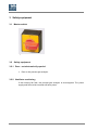
Fig. 3.1:
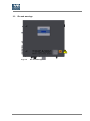
Fig. 3.2:
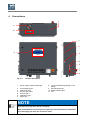
Fig. 4.1:
Fig. 5.1:
Fig. 5.3:
Fig. 5.4:
Fig. 5.5:
Fig. 5.6:
Fig. 7.1:
Fig. 8.1:
Fig. 8.2:
60
Master switch ................................................................................................ 14
IDs and warnings .......................................................................................... 15
Product description ....................................................................................... 16
Wall attachment ............................................................................................ 21
Electrical interfaces ....................................................................................... 24
Relay I/O board ............................................................................................. 25
Relay I/O board connection assignment ........................................................ 25
Analog output I/O board ................................................................................ 26
Workplaces ................................................................................................... 31
Operating elements ....................................................................................... 34
Display area .................................................................................................. 35