1
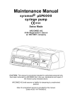
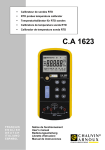
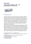
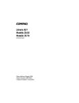
Maintenance Manual
Volumed® µVP7000
Swiss Made
ON
RATE ML/H
VOLUME ML
2 MIN
START
BOLUS
OPTION
OFF
STOP
volumed
µVP7000
RATE
KVO
INF
COMPL
DEFECT
ARCOMED AG
8105 Regensdorf / Zürich
(an ISO 9001 company)
Important
This manual is exclusively intended for authorized personnel who have been
instructed by Arcomed AG in the maintenance and repair of the Infusion Pump
indicated above.
Arcomed AG shall assume no liability for tampering by unauthorized persons.
Caution: The manufacturer reserves the right to improve the specifications of
this product without prior notice.
Edition 02/03 -VA-TM-7000-E
Contents
Page
Index numbers
0
1.
Introduction
1
1.2.2
Service Intervals
2
2.
Specifications
3
3.
Operation
4
3.18
Parallel / Multiple Infusions
10
4.
Alarm Supervision System
11
5.
Warranty
13
Design Changes
13
6.
Inspection and Maintenance Intervals
14
7.
Significance of Trumpet Curves
15
8.
Technical description
17
9.
Trouble shooting
21
10.
Replacement of parts
22
11.
Spare parts list 7000
23
Annex A
Drawings
Annex B
Schematics
Annex C
Component layout
Index Numbers
1
Administration set
2
Drip chamber
3
Stop flow clamp (internal or robson clamp)
4
Empty container detector (ECD)
5
Door
6
Door latch
7
On / OFF key
8
Rate display
9
Volume display
10
Start / Stop key
11
Tube guides
12
Pumping-peristaltic
13
Occlusion detector
14
Stop flow device
15
Air detector
16
Rate keys
17
Volume keys
18
Option key, Alarm tone-mute key
19
Prime / Bolus key
20
Alphanumeric LCD display
21
Alarm window
22
Information window
23
Mains supply socket
24
Fuses
25
Connector nurse call
26
Connector empty container detector (ECD)
27
External power supply (12 DC)
28
Infra red interface
29
Pole clamp
30
Carrying handle
11
4
12
7
11
3
14
1
2
15
11
6
5
7
6
ON
8
16
RATE ML/H
30
6
13
9
18
VOLUME ML
10
19
2 MIN
START
BOLUS
OFF
OPTION
STOP
RATE
KVO
INF
COMPL
DEFECT
arcomed ag
volumed
µVP7000
22
20
21
Volumed µVP7000
Front view
29
30
25
23
24
25
26
27
28
Volumed µVP7000
Rear view
1.
Introduction
1.0
Introduction
The Volumed® µVP7000 Volumetric Infusion Pump has been developed using
the latest state-of-the-art technology. This microprocessor-controlled volumetric
pump operates by pumping the infusate using a peristaltic system. The sterility of
the infusate is not affected. The pump is designed to infuse drugs or other
infusates into the patient by controlled means under pressure.
The Volumed µVP7000 meets the performance requirements of the MDA (UK) for
neonatal and high risk infusions. It can be used in both stationary and
transportable applications as it has a battery life up to 6 hours duration.
Applications include neonatology, intensive and cardiac care, paediatrics,
gynaecology and osbstetrics, surgery and general medicine. It can also be used
in ambulances or for laboratory use. For infusions with very small rates and small
volumes it is recommended to use a syringe pump such as the Syramed®
µSP6000 as the the remaining volume in the administration set can become
significant compared to the infused volume.
The Volumed µVP7000 meets the Medical Device Directive (MDD) requirements
of the EC Guideline 93/42 EEC and is marked CE.
Classification: Class IIb
The manufacturer according to MDD is Arcomed AG, Althardstrasse 146, CH
8105 Regensdorf, Zurich, Switzerland. Responsible for the EC is Arcomedical
Infusion Ltd., West Horndon, Essex CM13 3XS, UK.
The Volumed µVP7000 may be operated only on mains power installed to DIN
57107 VDE 0107 or the appropriate national standards. If the integrity of the
mains power supply protective earth system is in doubt, the pump should be
operated on battery power. Mobile telephones should not be used anywhere
near this equipment.
1.1
Mounting the pump
Check the pump and accompanying accessories for damage when unpacking.
The pump must not be operated if damaged. Should the pump be damaged
contact our Service Department.
Permitted mounting: positioned on a flat horizontal surface or pole mounted on
an infusion stand or rail mounted.
The pump should normally be operated from a mains power supply. The internal
batteries will automatically operate the pump in the event of a power failure.
CAUTION: This pump is not designed for use in areas where there is an
explosion hazard. Environmental requirements as per IEC601-1-2 must be
observed. Do not operate this pump in an environment with high levels of
electromagnetic radiation such as surgical diathermy or mobile telephones. For
further information contact the official distributor in your country or the Customer
Service Department in Switzerland:
Switzerland:
a r c o m e d a g, Althardstr. 146, CH-8105 Regensdorf
Tel. 0041 (01)840’47’40, Fax. 0041 (01)840’06’49
United Kingdom:
Arcomedical Infusion Ltd., 5g West Horndon Industrial
Estate, West Horndon, Essex CM13 3X
Page 1
Tel. 0044 (1) 277’81’04’32 Fax. 0044 (1) 277’81’19’67
The technical manual and the list of spares and used materials can be requested
from Arcomed.
1.2.1 Cleaning and disinfection
CAUTION: The pump must be switched off and disconnected from the mains
power supply before cleaning and disinfecting.
The pump must be kept clean and dry. Remove any spillage immediately. The
pump must not be placed in an autoclave.
The unit is disinfected by wiping over with a cloth which has been damped
slightly with an alcohol-based disinfectant. Take care when cleaning that no
liquid enters the inside of the pump case. Wait at least 30 seconds after
disinfecting before switching the pump on. Use only disinfectant that are
compliant with:
- ABS, POM, stainless steel, PVC, aluminum, silicone
Please check with your supplier of disinfectant.
1.2.2 Annual safety check
Battery power is provided by a nickel metal hydride (NiMH) battery which must be
checked annually. Battery condition is checked by connecting the pump to the
mains power supply for 15 hours in a switched off condition so that the battery
may be fully charged. Disconnect the mains power supply and switch the pump
on using battery power. Determine the operating time when the low battery alarm
activates. This should be at least 3 hours - if not the battery must be replaced.
Repeated charging and discharging may in certain circumstances cause
degeneration of the battery (memory effect).
Used batteries must be disposed of in an environmentally friendly manner or
returned to the manufacturer.
Safety checks (see chapter 6) may be performed only by qualified staff.
1.3.
Key to symbols
The pictograms and symbols shown on the reverse of the pump have the
following meanings or functions:
CF (cardiac floating) part
Nurse Call
Empty bag detector
12 VDC
!
IPX 1
CAUTION: consult accompanying
documents
Drip-proof
External 12 VDC supply
class II double insulated
IR
Interface RS232
(Infrared Interface)
Page 2
2.
Specifications
CE Mark
Classification
Software revision
Flow rate range (ml/h)
Volume range (ml)
A23 02 04 07000 01
IIb
1.xx
0.1 - 999.0 ml/h, increments: 0.1 ml/h
0.1 - 9999.9 ml, increments: 0.1 ml
Deviation in flow-rate with
8101P series administration set
Deviation in flow-rate with
3101P series administration set
typ. +/- 3% (Silicone insert)
typ. +/- 5% (PVC line)
Overinfusion in case of electrical
or mechanical defect
Keep vein open rate (KVO)
Bolus rate, Prime rate
Infusion pressure min.
Infusion pressure max.
1.5 ml max.
Alarm pressure limit
Bolus volume after occlusion
Time to alarm after occlusion
0 - 999 mbar/mmHg
Automatic bolus reduction (see also 3.9)
Depending on rate, pressure limit setting
and set, see also table below.
Air detection
Sensitivity
ultrasonic
typ. 100 µl, adjustable from 50 to 250 µl
Cumulated 15 min adjustable from
500 to 5000 µl
Battery operation time (1.85Ah)
Charging time
Supply voltage
External power supply (optional)
Input power
Mains fuse
3 - 5 hrs (dependent on rate and mode)
15 hours/20 hours
230 VAC+10%-15%, 50/60 Hz
12 VDC
9.3 VA
T200 mA/IEC127/III/SEV 1064
Type of protection against electric shock
Protection against ingress of liquids
Leakage current
Radio interference
Nurse call, potential-free
contact switch
Degree of protection against electric shock
Dimensions
Housing
Weight
Class II
IPX 1, drip proof
< 40µA
CE-Class A
24V/0.2A
3.0 ml/h, adjustable
1000 ml/h, adjustable
60 kPa / 450 mmHg / 0.6 bar
120-250 kPa / 900-1875 mmHg
1.5-2.5 bar (according to IV set)
CF (cardiac floating)
245x90x180 mm (WxHxD)
ABS plastic, UL listed
2.6 kg (approx.)
Page 3
Max. storage period
Permitted temperature range
(operation/storage)
Permitted relative humidity
3 months without charging
15°C - 35°C / 0°C- 40°C
Atmospheric pressure
Safety certification
500-1000 hPa
DIN IEC 601 Part 1
EN55011 Radio interference
IEC60601-1-2 Susceptibility
IEC60601-2-24
20-90% max. (no vapor deposit)
Operating modes
Continual, manual bolus, automatic bolus, priming.
Labeling of the pump
12 alpha numeric caracters.
Configured through IR interface.
History
Up to 1500 data logs with real time stamps.
Read out and printout through IR interface and PC.
Time to alarm after occlusion (PVC set), volume of bolus without bolus reduction:
Pressure
Rate
1.0 bar
500 mbar
100 mbar
1 ml/h
>60 min
45 min
8 min
20 ml/h
3.5 min
100 sec
20 sec
100 ml/h
50 sec
25 sec
5 sec
999 ml/h
6 sec
2.5 sec
0.5 sec
Bolus
0.9 ml
0.45 ml
0.09 ml
Page 4
3.
Operation
The figures in brackets refer to the illustrations of front and rear views shown in
the appendices.
CAUTION: Use only approved disposable adiministration sets!
(cf. leaflet "Accessories and Consumables")
The performance of the pump depends on both pump and administration set. The
volumed must only be used with the sets the pump has been calibrated to. The
functional safety of the pump cannot be guaranteed if non-approved IV sets are
used. The safety of the patient may be compromised as a result.
Disposable IV sets are for single-use only. Single-use needles carry an infection
hazard and must be disposed of in accordance with local guidelines. The IV-set
should be replaced every 24 hours.
3.1.
Preparation and loading of the administration set
a) If the pump is to be operated on an infusion stand, care must be taken that the
pump is not positioned more than 1.4m above the ground to ensure stability.
Ideally use an "Arco Luxe" or "Arco Standard" infusion stand. If several pumps
are mounted one above the other the maximum permitted height from the floor
must be observed and measures taken to prevent instability. The pump
may be fixed to the infusion stand by means of the pole clamp (29) on the rear
of the unit.
b) Slot the drip chamber (2) into the empty container detector (4). Make sure
that there are no large ribs or joints in the passage of the empty container
detector and that fallen drops are detected by the drop-detector‘s light-barrier.
c) Carefully purge the infusion set (1), without allowing any air bubbles to
enter, until the drip chamber (2) is 1/4 to 1/3 full. If air has entered, repeat
purge-procedure.
d) Close the tubing roller clamp.
e) Open the pump door (5) by pulling the latch (6).
f) Pump with Robson Clamp:
Position the Robson clamp (3) on the tubing. In case of a silicon insert
tubing, position the Robson clamp just left of the silicone segment. Close the
Robson clamp. Hold the tubing with your right hand with your thumb
positioned on the Robson clamp. Starting with the left side, insert the IV set
into the left tube guide (11). Ensure that the flow direction of the pump from
the left to the right is respected and the tubing is in a straight line. Put the
Robson clamp with your thumb into the Stop Flow device (14) and insert
the remaining tubing onto the right tube guide (11).
Pump with internal clamp:
Starting with the left side, insert the IV set into the left and right tube guides
(11). Ensure that the flow direction of the pump from the left to the right is
respected and the tubing is in a straight line. In case of a silicon insert tubing
verify the correct position of the silicon insert as shown in the front view of this
manual.
g) Close the door (5) and push the latch (6) firmly against the pump. Open the
tubing roller clamp.
Page 5
h) Switch the pump on: Press ON/OFF key (
) (10). The audible alarm
beeps once together with the indication < ! > in the alarm window (21). The
software version number (µVP7000, rx.xx) and the configuration of the pump
(µVP7000, c.xxx) light up briefly.
Wait until the automatic Stop Flow test is terminated.
i) Check if there is no free flow. Where possible mains power should be used.
Plug the mains power cable into the connector socket (18) at the rear of the
pump. The mains pictogram illuminates as soon as the mains supply is
connected. The battery is charged automatically.
j) The Volumed µVP7000 has the possibility to prime the line with the pump.
Make sure the patient is always disconnected when priming:
Press the bolus key (19) until the LCD display (20) shows: priming? Press and
hold the bolus key until the priming is finished. To terminate the piming mode
press the Start/Stop key (10). Important: during priming both air alarm and
empty bag alarm are ignored. The prime rate is displayed in the rate window
(8).
k) Connect set to the patient.
Important: Before the door is opened, close the roller clamp!
3.2.
Setting rate (ml/h) and volume (ml)
Use the UP/DOWN keys (16) to select the required rate in ml/h indicated in the
RATE display (8). Arrow up keys provide rate increase, arrow down keys provide
rate decrease. Check that each key stroke changes one digit. The least
significant digit (small size) indicates 0.1 (units).
If a specific volume (VTBI) is to be infused, the required volume in mls may be
selected in the VOLUME window (10) using the UP/DOWN keys (13) before
starting the pump (optional). Once the VTBI is reached, the pump gives and
audible alarm and displays <INF COMPL> (infusion complete) in the Alarm
window (21). The pump switches to the KVO rate.
Remark: With the empty bag detector (4) the pump stops automatically after the
last drop in the bag. If no empty bag detector is used, the volume (VTBI) has to be
set to stop before the bag is completely emptied. Otherwise the pump the pump
continues infusing until air is detected in the air detector (18). Hence, it is strongly
recommended to use the empty bag detector.
3.3.
Pump running
When the pump is running, the green drop symbol flashes (22). The VOLUME
display now indicates the volume infused in mls. In order to display various data,
such as pump condition, volume to be infused, infusion time, time to end of
infusion, battery condition, pressure and pressure limit, press the OPTION key
(18) sequentially and observe the LCD window (20) until the required data is
displayed.
If a specific volume to be infused was selected the pump automatically switches
to KVO operation when this volume has been infused and an audible and visual
alarm (21) activates.
Press the ALARM SILENCE key (5) to silence the audible alarm for 2 minutes.
Page 6
3.4.
Resetting the volume infused
In order to reset the volume infused, stop the pump by pressing the STOP key
(10). Press the OPTION key (18) for 2 seconds until the VOLUME display (9)
flashes. When the LCD window (20) displays "000", confirm this by pressing the
START/STOP key (10) to reset the volume infused to zero. If it is not desired to
reset the volume infused, press the OPTION key (18) until the normal display
appears.
3.5.
Infusing a bolus
When the pump is infusing, a manual or an automatic bolus can be given.
To infuse a manual bolus:
Press the OPTION key (18) and the BOLUS key (19) together.
The bolus rate is displayed in the RATE window (8) and the bolus volume infused
is displayed in the VOLUME window (9). The LCD window (20) indicates "Bolus
manual". Keep the keys depressed until the required bolus volume has been
infused. As soon as the keys are released the pump reverts to the normal
infusion mode.
To infuse an automatic bolus:
Press the Bolus key (19) for 2 seconds until the display in the VOLUME window
(9) flashes. The desired bolus volume in mls can then be preset in the VOLUME
display using the VOLUME keys (13). Press the BOLUS key (19) to deliver the
bolus automatically. If no bolus is required, press the OPTION key (18) to cancel.
During automatic bolus delivery, the RATE display (8) indicates the bolus rate
and the VOLUME display (9) indicates the bolus volume infused. The LCD
window (20) indicates "Bolus automatic".
To stop the pump at any time press the STOP key (10).
After the selected bolus volume has been delivered, the pump switches
automatically to normal delivery mode.
Following bolus infusion, the bolus volume is added to the total ml infused.
3.6.
IV container exchange
When changing the plastic container or bottle, infusion can be interrupted at any
time by means of the 'Start/Stop' key (18) without affecting the set or displayed
values. In this state, handling operations such as changing the container or IV set
and rate changes can be implemented without activating the alarm. In the stop
mode, 'KVO' operation is automatically activated.
If the pump remains in the stop mode for more than 4 minutes, the audible
reminder alarm will sound.
3.7.
Recall of previous data
If the pump has been accidentally switched off, data such as rate, volume to be
infused and volume infused may be recalled during start up. Press the
START/STOP key (10) and the ON/OFF key (7) together to recall all data.
3.8.
Setting volume and time
If a specific volume is to be infused in a given time the RATE display must be left
at zero. After inserting the IV set, closing the door and finishing the automatic test
press and hold the OPTION key (18) until the RATE and VOLUME displays flash.
Page 7
The time in hours and minutes may be selected in the RATE display (9) and the
volume selected in the VOLUME display (9). The pump automatically calculates
the infusion rate. Check this carefully in the LCD window (20) before starting the
infusion.
3.9.
Pressure system
The Volumed µVP7000 has automatic pressure monitoring whereby the pressure
in the system is measured via the pressure transducer. The alarm pressure limit
can be set automatically or manually.
Automatic setting:
If the pump is configured for this mode, the alarm pressure limit is automatically
matched to the set rate, the lower the rate, the lower the alarm pressure limit. The
time to alarm can be viewed in the table of section 2.
Manual setting:
Press the OPTION key (18) sequentially to display pressure and alarm pressure
limit in the LCD window (20). Hold down the OPTION key (18) until the VOLUME
display (9) flashes "Lxxx". The pressure limit may be manually set using the
VOLUME keys (17) in the VOLUME display (9) and the data in the LCD window
changes accordingly. This can also be done while the infusion is in progress.
NOTE: Manual setting of pressure deactivates the automatic pressure setting, i.e.
the pressure remains at the current level independent of the rate selected.
If the pressure rises beyond the limit set, the pump stops and the stored bolus is
automatically reduced to virtually zero volume. An audible and visual alarm is
activated. Check the IV carefully for the cause of the alarm. Do not restart the
pump until the occlusion is released.
3.10. Setting time and date
Press the OPTION key (18) sequentially to display date and time in the LCD
window (20). Hold the OPTION key (18) down until the display flashes. The time
may be set using the volume keys (17) in the Volume display (9), e.g. h9.45 =
9:45 am. This can also be done while the infusion is in progress.
The Volumed has the possibility to automatically adjust the daylight save time
(summer time). The adjustments can be done as per EU, US or Australian
regulations. If the text ‘Clock !’ should appear, replace the Lithium backup battery
on the main PCB.
To set the date, first switch the pump off. Press the VOLUME 0.1 ml DOWN and
VOLUME 100 ml DOWN keys (17) together whilst switching the pump on. This
enables the Service Mode. Select the RATE display (8) according to the
following table using the RATE keys (16). Then select the corresponding data in
the VOLUME display (9) using the VOLUME keys (17). Press the START key (10)
each time to confirm each setting:
Rate
display (9)
145
144
143
142
Volume
display (10)
0 - 99
1 - 12
1 - 31
1-7
Function
Year
Month
Date
Weekday (Monday = 1, Sunday = 7)
Press the ON/OFF key (7) to switch the pump off.
Page 8
Note: Incorrect setting of date or time does not affect the correct functioning of the
pump.
3.11. Different configurations
If a different configuration is required, please contact our Customer Service
Department or the official ARCOMED distributor in your country.
3.12. Accessories and consumables
Accessories, expendable parts and single-use items may only be used if they
comply with the appropriate international standard and national approvals. Sets,
filters and extension sets must be CE marked. The ordering numbers can be
found on the leaflet "Accessories and Consumables"
The Instructions for Use, the mains power supply cable and the empty bag
detector (optional) are included as standard equipment with the Volumed
µVP7000. For accessories see also 3.19.
3.13. START/STOP key (10)
The START/STOP key (10) is used to start the pump after the rate has been
selected. The pump may be stopped at any time using this key. An additional
function of this key is to confirm various parameters.
3.14. Prime / Bolus key (19)
The PRIME/BOLUS key (19) key is used to prime the extension set. It is also
used to initiate a manual or automatic bolus (3.5).
3.15. AUDIBLE ALARM SILENCE/ OPTION key (18)
The audible alarm may be silenced for 2 minutes using the ALARM
SILENCE/OPTION key (18). The audible alarm is re-activated after this period.
If there is no audible alarm, the key serves as an OPTION key which enables
selection of any option.
3.16. ON/OFF
key (7)
The pump may be switched off using the ON/OFF key (7) if the infusion has been
completed. All data displayed (rate and volume) is lost when the pump is
switched off. In order to avoid switching the pump off accidentally, the ON/OFF
key (7) must be pressed for at least one second before the pump switches off.
If the pump is connected to the mains, the STANDBY mode will switch in when
the pump is switched off. This means that the battery will be charged and the
charge condition indicated in the LCD window.
3.17. Keep-Vein-Open (KVO) - Rate
The pump may be configured to infuse at the keep vein open rate when the
volume to be infused has been delivered. The KVO rate is preset at 3.0 ml/h and
may be set (by a technician) to suite individual requirements if necessary. If the
set rate is smaller than than the KVO rate, this rate becomes the KVO rate.
Remark: The latest standard uses the new wording Keep-Open-Rate (KOR). The
meaning is identical to the KVO-rate.
Page 9
3.18. Using the pump in parallel or multiple infusions
If additional infusion systems are connected to the patient's vascular system, this
may lead to complications e.g. infusion of air, reverse-flow, interruptions due to
alarms and inaccurate flow.
To prevent such incidents, please observe the recommendations as stipulated in
DIN VDE 0753, Part 5 or contact your distributor.
3.19. Options for external connection to the pump
External equipment may only be connected to the Nurse call connector (25),
empty bag detector (26) and external supply (27) if the system which results from
this meets the requirements of standard EN60601-1-1 and if their safety has
been certified by an approved international body.
- Use cable number 94070 to connect the Nurse call system. Important: The
alarms on the pump have to be observed also when the nurse call is connected.
- If an external 12 VDC power supply is used and is linked to other equipment,
ensure that the safety of the system complies with IEC60601-1. Use cable
number 71630.
- Use only the external empty conntainer detector Nr. 98502 (4)
Please contact the Customer Service Department of ARCOMED AG for details of
the RS232 interface (IR interface) and how to link it to external systems.
Page 10
4.
Alarm system
4.1.
Alarm causes
The electronic self-monitoring system continuously monitors the correct
functioning of the pump and its displays whilst in operation. If a fault should
occur, the infusion is stopped
immediately and the alarm activates. The corresponding alarm symbol is
illuminated continuously with a red colour and there is a continuous audible
alarm. The nurse call alarm is activated at the same time.
The pump will not start:
- if no rate has been set (0 ml/h).
- if air is in the line
- if the door is open.
- if the IV set or the Robson clamp is not correctly installed.
During operation an audible alarm activates and the pump switches to the KVO
rate if:
- the START/STOP key is operated.
- the VTBI is reached
- attempts are made to alter the rate during operation.
During operation an audible alarm activates and the pump stops if:
- the roller clamp is not opened.
- the bag is empty.
- battery capacity is low and the charge can no longer ensure controlled infusion.
- the infusion pressure exceeds the limit set.
- the door is opened.
- there is an internal defect.
With empty bag detector:
- if the detected drops do not correspond with the set tolerances.
- if the level in the drip chamber is too high.
4.2.
Canceling the alarm condition
After rectifying the cause of the alarm or acknowledging the rate change, the
alarm condition is canceled and infusion resumed by pressing the START/STOP
- key (10).
4.3.
Pressure limit/occlusion alarm
If the pressure in the system reaches the set pressure limit due either to a total or
partial occlusion, the alarm activates and the occlusion alarm symbol and rate
display flash. The LCD window displays "occlusion! check line!" The vein site
should be checked to ensure there is no complication.
If the cause of the occlusion is removed, the occlusion symbol flashes and the
pump may be started again.
Page 11
4.3.
Battery alarm
The pump may be operated independently of the mains power supply using the
internal battery. If the mains power supply fails, the pump switches automatically
to battery operation to continue the infusion without interruption.
Battery operation is indicated by illumination of the battery symbol (22). Battery
capacity permits from 3 up to 6 hours operation (1.85 Ah battery) depending on
the infusion rate set. After approximately 3 to 6 hours operation the battery
symbol in the alarm display (21) illuminates and an audible alarm activates.
Alarms are canceled automatically as soon as mains power is restored.
A low battery alert is activated approximately 30 minutes before the battery
depleted alarm. The battery symbol (21) flashes and an audible alarm activates.
To silence the audible alarm, press the ALARM SILENCE key (18). The battery
symbol continues to flash until the pump is reconnected to the mains.
A cautionary alarm is activated if the pump is disconnected from the mains power
supply whilst in operation. This alarm may be silenced using the ALARM
SILENCE key (5).
4.4.
Nurse call
The pump may be connected to the external nurse call system via the connector
(25) on the rear of the unit using cable part number 94070. All alarms are
transmitted to the nurse call station. The normal pump alarms and displays
continue to function.
4.5.
Alarm silence
Audible alarms may be silenced for approximately 2 minutes using the
ALARM/SILENCE key (18). The audible alarm is reactivated after this period.
4.6.
Alarm indicators (18)
The cause of the alarms are indicated using illuminated pictograms as shown:
KVO keep vein open rate
RATE
Rate changed
4.7.
KVO
Occlusion alarm
Empty bag alarm
INF
COMPL
Defect
DEFECT
Infusion complete
Air alarm
Power and running indicators (22)
These are indicated by the following:
Pump running
Mains operation
Battery operation
Page 12
Battery alarm
4.8.
LCD window (20)
Various messages and infusion parameters are displayed in this window.
4.9.
Technical description
The Volumed µVP7000 is a microprocessor-controlled infusion pump with
stepper motor drive and comprehensive software management function
monitoring. The pump is operating range enables infusion rates from 0.1 ml/h to
1, 999 ml/h to be made. An internal rechargeable battery allows the unit to
operate independently of the mains in emergencies or when used as a mobile
unit. The mechanism is driven by a step motor via a toothed belt and friction
spindle. All important operating parameters are clearly shown on an LED
indicator. Setting the desired values is done via touch-pad keys. The unit is
manufactured using the latest surface mounted control technology (SMD).
5.
Warranty
Arcomed AG offers a twelve month warranty on each Volumed µVP7000
volumetric pump effective from date of delivery.
The warranty covers the installation and replacement of faulty parts if caused by
faulty assembly or materials. The warranty is rendered null and void if changes or
repairs are carried out by persons who have not been authorized in writing to do
so by Arcomed AG or Arcomedical Infusion Ltd and if the inspection and
maintenance intervals are not observed.
The warranty does not cover the elimination of problems caused by incorrect
operation, inappropriate handling or normal wear and tear,
The supplier only accepts responsibility for the safety, functional reliability and
performance of the equipment providing that
- assembly, extension work, resetting, modification or installations are carried out
by personnel authorized by him.
- the electrical system at the operating site meets IEC requirements.
- the unit is used in accordance with these Instructions for Use.
The information provided in this manual applies to the currently prevailing
situation and is given in good faith. The manufacturer reserves the right to make
modifications in the interest of technical progress.
5.1. Design changes
Arcomed AG endeavour to ensure that future improvements and modifications
are compatible with earlier models.
NOTE: Always state the model, serial number and where applicable the colour of
the unit in question when ordering spares.
Page 13
6. Inspection and maintenance intervals Volumetric Infusionpump
Volumed ® µVP7000 (according MDD)
Interval: After 24 m months or 10’000 h of use.
The following checks must be done by an engineer with sufficient technical background to comply with
the safety regulations.
What to do
How / Equipment
Remarks Result
Visual Check
Housing
External emty container detector (ECD) (Easy Clip)
or Internal empty container detector (ECD) ( especially spring )
Door, door latch
Stop-flow lever
Cover for peristaltic blades
Inscriptions, display
Display - LED
Mains plug, fuses
Air in line
Physical damage
Physical damage
Physical damage
Clean, function
Clean, function
Physical damage
Readable, damage
Function, display test
Damaged, values
Physical damage
Functional checks
o Spring plate
manual
o Pressure checks:
IV-set filled with water,
manometer & tubing
o minimal mechanical pressure:
preload system with
syringe to 0.7 bar
4 min. at rate 5 ml/h
(press. limit 999 mbar)
watch manometer
pressure always
above 0.6 bar
p min =
rate 400 ml/h
(press. limit 999 mbar)
pressure always
below 2.5 bar*
p max =
o Pressure Sensor:
rate 100 ml/h
pressure limit 500 mbar
make occlusion on set
alarm reaction
within
20 sec ±10 sec
o Rate check:
Rate 100 ml/h
Total of 100 ml
± 5 % accuracy*
Refer to trumpet
curve (tech manual)
Take out drop chamber
of ECD detector
Visual and acoustic
alarm
o simulate Air in Line
Air bubble (eg reverse
drip chamber) in the line
Visual and acoustic
alarm
o check nurse call
e. g. open door while
pump is running
alarms and switching
signal at connecter
o (External pump stop
only Option RS 232C)
Electrical safety according to IEC 601
o Leakage current
o Resistance protective conductor
Safety Tester IEC 601
≤ 75µA
≤ 100 mOhm
o maximal mechanical pressure:
while running on 100 ml/h
o simulate missing drops
check free motion
o alternative test
PTD-7000
o alternative test
VT-5000
% dev =
IEC 601.1, section 19
The rates of the fuses must comply with the rates recommended by arcomed (producer):
Conventional transformer 230V :100 mAT/250V, toroid transformer 230V: 250 mAT/250V,
toroid transformer 115V: 500mA T/250V ( IEC127/III/SEV 1064).
Caution: After any work on the pump (e. g. adjustment of programming, change of parts, any opening of the
pump) this inspection must be made and all checks must be documented with the serial number of the pump.
* depending on set (eg. 3101P PVC 2.5 bar, ± 5%, 8101P Silicone 1.5 bar, ±3%).
Serial Number:
Remarks:
Page 14
Date /Signature:
7. Perfomance
7.1 Significance of trumpet curves for practical use
Trumpet curves indicate for 5 different observation windows the maximum and minimum
mean values of the flow rate in ratio to the preset flow rate.
Known therefore is the discrepancy per time-window. For optimal use of the infusion
pump Volumed® µVP7000, the trumpet curve is an important factor in deciding whether
the pump can be used with the prescribed drug.
Volatile drugs with short therapheutic half life demand high accuracy.
For a drug where the plasma-half life is e.g. 1 min. discrepancy of the flow rate of 15%
per minute would mean the same discrepancy for the plasma level. Therefore, a
predictable constant impact of the drug would not be guaranteed.
Example:
Intraveinous infused Insulin has a therapheutic half life of 15 minutes. A flow deviation of
± 15% within 40 minutes would have at least the same (rather twice as much) influence
on deviation of the plasma level and therefore on its impact.
This is inacceptable to physicians and nursing personel.
It is important to know that the deviation in a short observation window depends strongly
on the preset rate. The Volumed® µVP7000 has at a rate of 25 ml/h a deviation smaller
than ±2% in a observation window of 2 minutes.With 5 ml/h the deviation in the same
observation window is ± 7%, within 5 minutes it is ±3%. Mean deviations are within ±5%
(see also following table).
Table 1: Flow Accuracy of the Volumed® µVP7000 (typical values)
Rate (ml/h)
2 min
Max
5.0
25.0
100.0
Rate (ml/h)
5.0
25.0
100.0
+6.93%
+4.54%
+0.60%
eff. Rate
(ml/h)
5.010
24.800
101.182
Min
Max
-5.99%
-3.65%
-1.17%
5 min
Min
+3.08% -3.45%
+1.39% -1.46%
+0.28% -0.76%
Abweichung Stand.-Abweichung Testzeit Messzeit
(%)
(ml/h)
(h.min)
(h.min)
0.203
-0.399
1.182
0.010
0.200
1.182
Page 15
2.00
2.00
2.00
1.00
1.00
1.00
File Name:
25ml/h IEC 7000
ø Flow (2nd h):
ø Error[%] (2nd h):
25.788
3.153
Rec. date:
Rec. time:
Rate (ml/h):
11.2.2002
10:54:24 Uhr
Evaporation:
25.0
0.00
# Scans:
Interval (s):
240
30
Flow [ml/h]:
50.0
37.5
25.0
12.5
0.0
0:00
0:10
0:20
0:30
0:40
0:50
1:00
1:10
1:20
1:30
Trumpet Curve (2nd h):
1:50
2:00
2 Min (max): 2 Min (min):
10.0
4.54
-3.65
5 Min (max): 5 Min (min):
5.0
1.39
-1.46
11 Min (max):
11 Min (min):
0.0
0.60
-0.88
19 Min (max):
19 Min (min):
-5.0
-10.0
0:00
1:40
0.57
-0.37
31 Min (max):
31 Min (min):
0:10
0:20
0:30
0.28
-0.33
File Name:
5ml/h IEC 7000
ø Flow (2nd h):
ø Error[%] (2nd h):
5.010
0.203
Rec. date:
Rec. time:
Rate (ml/h):
19.2.2002
10:07:52 Uhr
Evaporation:
5.0
0.00
# Scans:
Interval (s):
240
30
Flow [ml/h]:
10.0
7.5
5.0
2.5
0.0
0:00
0:10
0:20
0:30
0:40
0:50
1:00
1:10
1:20
1:30
Trumpet Curve (2nd h):
1:50
2:00
2 Min (max): 2 Min (min):
10.0
6.93
-5.99
5 Min (max): 5 Min (min):
5.0
3.08
-3.45
11 Min (max):
11 Min (min):
0.0
1.77
-0.91
19 Min (max):
19 Min (min):
-5.0
-10.0
0:00
1:40
1.23
-0.52
31 Min (max):
31 Min (min):
0:10
0:20
0:30
0.71
-0.14
8.
TECHNICAL DESCRIPTION
8.1
Introduction
The microprocessor controlled peristaltic pump Volumed® µVP7000 is supplied
with a step motor drive and comprehensive software monitoring. The operating
range of the pump allows rates from 0.1 - 999ml/h to be selected. An integrated,
rechargeable battery permits mains-independent operation for emergencies or
for ambulatory use.
A stop flow device is installed behind the door to prevent the infusion solution
from flowing freely in the event of the pump door being opened inadvertently. The
peristaltic system is driven by a step motor via a positive-engagement toothed
belt, with the individual blade movements being controlled by an eccentric
camshaft. These blades are fully protected by a rubber cover.
All important operating parameters are clearly reproduced on an LED display.
The desired values are entered via a keypad.
All important operating parameters are clearly shown on two LED displays with
an additional LCD for messages and various other data. Infusion parameters are
set via touch keys which comprise a mechanical switch covered by a sealed
membrane. The unit is manufactured using the latest surface mount technology
(SMT).
In the circuit description that follows, reference is made to diagrams 1 to 3.
8.2.
Circuit description
8.2.1. Microcontroller
Microcontroller D0 monitors the following signals:
Motor controller
The step motor drive D8 is controlled directly by the microcontroller and operates
in chopper mode. The step motor operates in micro-steps to provide continuous
and smooth delivery even at low flow rates.
Main shaft revolution pulses
A Hall sensor adjacent to the main shaft produces a pulse for each revolution of
the shaft. In the microcontroller this is monitored by software on a frequency/time
basis.
Watchdog
The external Watchdog in IC D2 monitors program run time. If the limits are not
within the specified time, the semi-conductor relay VO interrupts power to the
step motor. A fault is signaled to the microcontroller via the inverter D7.
The relay D10 is periodically switched off for a short period to test the watchdog
and the correct functioning of the microcontroller is monitored. There is a second
watchdog in the microcontroller.
Page 17
Operating voltages
The supply voltage, the 5V logic supply rail and reference voltage are measured
and monitored via disc resistors by the analog/digital converter in the
microcontroller.
Mains/battery operation
The level of the operating voltage determines whether mains or battery operation
is used.
Battery voltage
The battery alarm activates if the minimum operating voltage falls below the set
limits during battery operation. The unit will be shut down in the case of
exhaustive voltage discharge.
Logic rail voltage
The rail voltage is limited to a maximum of 5.5V by diode V20, and transistor V5
triggers the microcontroller and external Watchdog if 5.8V is exceeded. If the
level reached is less than 4.5V, the integrated circuit D2 initialises the system.
Microcontroller D1 controls the following signals:
Step motor pulses
The step motor pulses are fed by the microcontroller from the quartz oscillator at
a frequency corresponding to the rate set.
Watchdog
Watchdog D2 is triggered periodically after each program run.
Buzzer (audible alarm)
Dependent on the operating status the microcontroller activates the audible
alarm trigger K1 via driver V9.
Alarm relay
Dependent on the operating status the microcontroller activates the alarm relay
KO (Nurse call) via driver V8.
On/Off function
After start up the microcontroller triggers a hold of the semi-conductor relay V12
via the Power-Hold line. The supply voltage remains switched on. When
operating the ON/OFF key or if the battery is discharged the microcontroller turns
the supply voltage off via the semiconductor relay V12.
A/D converter
The microcontroller controls the internal A/D converter and measures the results.
Page 18
Infra red interface
The microcontroller sends and receives data via IC's D10 to D12. The encoder
D10 converts the signals to Standard IrDA 1.0. The unit can receive and transmit
data from above (D11), below and to the rear (D12). This provides a wire-less
connection between units mounted on top of each other.
EEPROM memory
Set values and important data are held in non-volatile memory D3 and/or
recalled from there and remain available even when the pump is switched off.
Even when the battery is fully discharged data is not lost.
SRAM memory and real time clock
IC D2 is an external SRAM and provides storage of a multitude of data.
Simultaneously time and date can be read from the real time clock. The real time
clock is buffered by a special battery and can work independently for up to 10
years even when the battery is fully discharged. The clock is only an indicator. An
incorrrect date or time will not effect the normal functioning of the pump.
8.2.2. Display
The operating status is depicted by the LED displays and illuminated pictograms.
Display drivers M2, M3 and M4 are controlled by the peripheral IC's D3 and M1
and multiplexed by the microcontroller.
Rate
Volume
Alarm pictograms
Pump infusing
Battery operation
Mains operation
4-digit red numerals
5-digit red numerals
red LEDs
green LED
green LED
green LED
8.2.3. Inputting infusion parameters
All data inputs are made via keys which are periodically checked by the microcontroller.
Only the ON/OFF key is connected separately and controls the start-up logic or releases
a delayed shut-down via the microcontroller. The keys have the following functions:
Function:
Key:
Start -up/Switch off pump
Rate setting
ON/OFF
Rate 100 ml/h up/down
Rate 10 ml/h up/down
Rate 1 ml/h up/down
Rate 0.1 ml/h up/down
Volume setting
Volume 1000ml up/down-Volume 0.1 ml up/down
Start/Stop
START/STOP pump
Prime/Bolus
Prime/Bolus key
Alarm silence/Option
2 MIN, Option
(In an emergency the audible alarm is silenced for 2 minutes)
Page 19
8.2.4. Power supply
Mains power is supplied via a toroidal transformer and the rectifier V10. In the
event of a mains power supply failure, power is supplied without interruption by
the internal battery. The charge switch V14 ensures the battery is constantly
charged when the unit is connected to the mains (even when the unit is switched
off). Relay V12 switches the supply voltage on or off.
On the one hand this function is controlled by the ON/OFF key and by a
command from the microcontroller via the inverter D7.
On the other hand the microcontroller can in the same way trigger the shut down
of the supply voltage. The circuit controller D13 produces the +5V rail voltage.
8.2.5. Monitoring
Microcontroller:
On start up the registers are
checked for initial status and a
RAM test performed.
Air bubbles:
50 µl detection limit, integration over 15 min.,
individual bubbles > 50 - 250µl adjustable
Cumulative air alarm over 15 min
adjustable 500-5000µl
every 120 ms.
Air detector test:
Pressure:
Contious monitoring of pressure in the line in
mbar or mmHg.
Pressure limit 1…999 mbar/mmHg settable.
Empty bag detector:
(Option)
Alarm after 330 µl no drops
Alarm after 660 µl if < 5 drops
Alarm after 660 µl if ≥ 22 drops (adjustable)
Pump camshaft:
One revolution of the pump camshaft requires 246
step motor pulses. For each complete revolution of
the pump camshaft, the hall pulse initiates a
comparison with the number of step motor pulses
supplied. Tolerance per revolution +/- 20% pulses.
Functional check every 62 msec.
A key actuated for more than 60
seconds triggers a fault signal.
On start up the registers are
checked for initial status and a
RAM test performed.
Continuous ROM, RAM and CPU test during delivery.
External watchdog monitors programme run time;
approx. ±15%.
Microprocessor monitors the following voltages:
- mains/battery changeover threshold: 15V
- Battery charged: 11V
Semiconductor relay:
Keypad:
Microcontroller:
Program run time:
tolerance
Operating voltage:
Page 20
9.
Audible alarm repeat:
- Battery discharged: 9V
- 5V rail monitoring < 4.5V: fault signal > 5.8V: fault
signal
- A/D converter: defect >2.5%: fault signal
On 0.6 sec Off 3.0 sec
Other functions:
- Audible alarm in standby mode
Trouble shooting
When a DEFECT signal is given a fault code is displayed automatically.
In the Volume ML (12) window a 2-digit figure appears and the cause of the fault
indicated is listed in the table that follows. When a fault occurs the code appears
automatically as F-xx.
Code (Volume ML) Meaning:
Measure:
0
2
3
4
5
6
7
8
9
10
11
12
13
14
15
16
17
18
19
>20
Replace main PCB
Replace main PCB
Check drive
Replace main PCB
Check stop flow driver
Replace main PCB
Replace display PCB
Replace main PCB / Lithium battery
Replace EPROM
Replace main PCB
Check all EEPROM values
Replace main PCB / Lithium battery
Replace main PCB
Replace main PCB
Replace main PCB
Replace main PCB
Replace main PCB
Replace main PCB
Replace main PCB
Check pump / replace main PCB
Program sequence
Step motor too fast
Step motor too slow
AD converter fault
Stop flow clamp fault
Supply voltage
Key blocked
Watchdog Test
CRC Test EPROM
Run time
CRC Test EEPROM
Watchdog test 1
Initial CPU test
Register test
SRAM test
Bit-walk Test RAM
CPU Test (Instruction set)
Stop flow (battery)
Stop flow (mains)
combined errors
Page 21
10. Replacement of parts
The Volumed symbol µVP7000 may only be repaired by ARCOMED AG or
persons officially authorised in writing by Arcomed AG or Arcomedical Infusion
Ltd to do so.
In the event of a warranty claim please send the unit to the address shown in
Chapter 1.1.
CAUTION: The unit must be switched off and the mains connection removed
before commencing repairs.
a) Dissassembly of case:
Remove the two tie screws in the pole clamp on the rear of the unit and separate
the two sections of the case. First check and record the positions of all connectors
and the disconnect those between the front and rear assemblies where
necessary. Ensure that all connectors are correctly positioned and inserted when
reassembling the unit (see Topography Main PCB).
b) Removal of the main PCB:
Undo the four screws between the main PCB and the chassis.
CAUTION: Sensitive electronic parts can be damaged by static voltage if the
main PCB is handled incorrectly. Be sure that correct cable connections are
made when reassembling unit (refer to socket positions on the leaflet Main PCB
Topography).
The connector PCB is also fixed by two screws.
c) Removal of the display PCB and covers:
Undo the eight screws at the rear of the door which hold the door assembly
together. Undo the five screws between the PCB and the front door section and
carefully remove the PCB. After reassembly ensure the correct key functioning.
d) Removal of the mecanical assembly (drive):
After removal of the main PCB undo the mounting screws and spacers holding
the mechanical assembly to the case. Carefully withdraw the whole drive and
disconnect the hall cable. The mechanism can then be removed from the case.
Re-assemble in reverse order. Check that the cabels are connected firmly (front
print, hall sensor, pressure sensor) and the DC motor cable is fed through the
opening in the side plates. When assembling the main pcb, check the stepper
motor cable to be in the corresponding space.
Page 22
11. Volumed µVP7000: List of spare parts
Please quote the serial number of the pump when ordering.
Part no. Description
70000
70010
70020
70030
70050
70070
70080
70100
70110
70120
70131
70140
70160
70170
70180
70200
70270
70280
70320
70370
70470
70490
70550
70570
70585
70770
70800
70810
70830
70860
70901
70911
70920
70940
70960
71160
71170
71180
71210
71230
71240
71250
71260
71271
71690
71700
75000
75010
75020
75030
75040
75050
75060
Assy
Rev.
Case rear
Back 1
BC00
8mm safety ring
Back 1, Front 1
BC00
Rubber foot - blue
Back 1, Front1
BC00
Screw M3/10
Back 5
BC00
Nut M3
Door 2
BC00
Mains connector
Back 5
BC00
Plastic screw 3 x 10
Back 3, Front 5
BC00
Fuse T200mAT/250V
Back 5
BC00
IR window
Back 6
BC00
Cylinder screw M4x6
Back 4
BC00
Toriodal transformer 9.3VA 230V
Back 4
BC00
Toriodal transformer 8.5VA/110V
Back 4
BC00
Tie 6000
Back 7
BC00
Handle 6000
Back 7
BC00
Bolt 4x20
Back 7
BC00
Ferrite Transformer
Back 4
BC00
Mask LED
Door 3
BC00
Foil 1 x 3 LED
Drive9/Door3
BC00
Plastic screw 2.5 x 6
Door 2, Door 6
BC00
Plastic screw 2.5 x 16
Door 7
BC00
Drive pully 13MXL complete
Drive
BC00
Cylinder screw M3x8
Front 9, Front 10 BC00
Magnet ø3 x 3
Drive 12
BC00
Drive pully 32MXL complete
Drive 12
BC00
Pulley No 5
Drive, StopFlow
00
Plastic screw 2.2 x 8
Drive 6, Front 3
BC00
Gear weel
Drive 10
BC00
3m nurse call cable
final
BC00
Ferrite Nurse Call
Final
BC00
Micro fuse T1A battery
final
BC00
EPROM M 27 C 512
Front
BC 25
Main PCB 6000/ 4 BC 25 (extended Eprom 512) Front
BC25
O-ring tie
Back
BC00
Spacer M3x40
Front 2
BC00
Door rod
Front 2
BC00
Battery 9.6V/1.85Ah
Front 9
BC00
Battery holder
Front 9
BC00
Mounting plate back
Front 9
BC00
Lithium battery time keeper
DA mit Hauptprint BC00
Labels ø8mm
final
BC00
Screw M3/10
Back 5
BC05
Cylinder screw M3x4
Back 5
BC05
Screw M3x4
Back 5
BC05
Seal mains cable
Back 5
BC55
Backlight
Displayprint
BC00
LCD Display
Displayprint
BC00
Case front
Front
BC00
Door external part
Door
BC00
Door internal part
Door
BC00
Lever left and right
Door
BC00
Bearing plate
Front
BC00
Plate air in line detector
Front, Door
BC00
Plate pressure sensor
Front
BC00
Page 23
Material
ABS
steel
Santoprene
steel
steel
plastic UL94V-0
steel
glass/steel
polyamide
steel
ABS / copper
ABS/Cu
aluminium
steel
steel
ferrite
ABS
PVC
steel
steel
POM
steel
magnet
POM
POM
steel
steel
cable
ferrite
electronics
electronics
electronics
Santoprene
steel
steel
NiMH
steel
steel
Litium
PVC
steel
steel
steel
steal, rubber
electronics
electronics
ABS
POM
POM
POM
POM
POM
POM
75070
75080
75090
75100
75110
75120
75130
75140
75150
75160
75170
75180
75200
75210
75220
75230
75240
75250
75260
75270
75280
75290
75300
75310
75320
75350
75360
75370
75380
75390
75400
75410
75420
75430
75440
75450
75460
75470
75480
75490
75500
75510
75520
75530
75540
75550
75560
75565
75570
75580
75590
75600
75610
75620
75630
75650
75660
75670
75680
Apdapter PVC 7000
Case Stop Flow
Stop Flow Adapter
Stop Flow Adapter standard
Actuator Stop Flow
Side Plate 7000
Slider 7000
Back plate 7000
Mounting plate 7000
Frontpanel 7000
Transformer mounting plate
Camshaft 7000
Door support
Chassis pump bloc 7000
Door hinge (right)
Door hinge (left)
Clutch 7000
Motor connection 7000
Joint cable 7000
Spacer M3 x 50
Insert thread M2 x 3
Screw M1.6 x 8
Screw M2 x 12
Screw M2 x 8
Screw M2 x 4
Ball bearing ø10/ø3 x 4
Screw PT 4 x 25
Screw PT 4 x 30
Washer M3/3.2/9/1
Screw M3 x 10
Spacer tube 4*0.4*4
Spacer tube 4*0.4*5
Spacer tube 4*0.4*6
Hall pcb complete 7000
Bolt 1.5 x 10
Screw for plastics 2.5 x 12
Screw for plastics 2.5 x 10
Screw for plastics 2.2 x 4.5
Foil 1 x 1 LED
Display pcb 7000
Connector PCB 12V 7000
Front PCB 7000
Pressure sensor 7000
Spacer M3 x 8
Screw M3x12
Bolt 4 x 16
Stepper Motor 7000
Stepper motor 7000
DC Motor 7000
Motor belt 40 MXL 7000
Motor support 7000
Spindle for door 7000
Main PCB 7000
Clutch complete 7000
Tube seal
Sticker Front view µVP7000
Sticker Condensed instr. µVP7000-D
Sticker Condensed instr. µVP7000-F
Sticker Condensed instr. µVP7000-E
Front
StopFlow
StopFlow
StopFlow
StopFlow
pump bloc
pump bloc
pump bloc
Back 2, StopFlow
Door
Back 4
pump bloc
Door
pump bloc
Front
Front
pump bloc
pump bloc
door
Front
StopFlow
StopFlow
StopFlow
StopFlow
StopFlow
pump bloc
pump bloc
pump bloc
pump bloc
pump bloc
pump bloc
pump bloc
pump bloc
pump bloc
Door
door
Door, Front
Door, Front
Door3
Door
Back
Front
p sensor
Front
Front
Front
Pump bloc
Pump bloc
StopFlow
Pump bloc
pump bloc
Door
Front
BC00
BC00
BC00
BC00
BC00
BC00
BC00
BC00
BC00
BC00
BC00
BC00
BC00
BC00
BC00
BC00
BC00
BC00
BC00
BC00
BC00
BC00
BC00
BC00
BC00
BC00
BC00
BC00
BC00
BC00
BC00
BC00
BC00
BC
BC00
BC00
BC00
BC00
BC00
BC00
BC00
BC00
AC105
BC00
BC00
BC00
00
BC00
00
00
BC00
BC00
BC00
BC00
Dichtung Exzenter BC00
Front
BC00
final
BC00
final
BC00
final
BC00
Page 24
ABS
POM
POM
POM
POM
POM
POM
POM
PVS-G
PVS-G
steel
steel
steel
steel
steel
steel
Brass
Brass
Rubber
steel
Brass
Iron
Iron
Iron
Iron
Steel
steel
steel
steel
steel
steel
steel
steel
electronics
steel
steel
steel
steel
PVC
electronics
electronics
electronics
electronics
steel
steel
steel
iron / copper
Iron / cupper
iron / copper
rubber
steel
steel
electronics
Brass/rubber
NBR
PVC
PVC
PVC
PVC
92201
92461
93980
98100
98275
98435
98635
98641
98643
98780
98932
99290
99360
99565
99730
99810
99820
99950
Pump housing (blade housing)
Blade
Ball bearing dia. 6/19x6
Spacer M5/60mm thread inside
M3 / 3,2 safety ring
Sticker Battery
Cover P-Sensor (blue)
Adapter P-Sensor
Adapter P-Sensor PVC
Magnet EC
Rubber cover for peristaltic blades
Plate ultrasonic for air detecter
PXE plate
screw M3x4
Eccentric disk
Screw 3.9/9.5
Screw 3.9/13
Silent bloc 8/8
pump bloc
pump bloc
pump bloc
final
Pump bloc
Front
p sensor
p sensor
p sensor
Easy Clip
pump bloc
air detector
air detector
back
pump bloc
pump bloc
pump bloc
pump bloc
Page 25
AC040
AC040
BC00
BC00
BC00
BC00
BC00
BC00
BC00
AC045
AC040
BC00
BC00
BC00
BC00
BC00
BC00
BC00
POM
POM
stell
iron
iron
PVC
POM
ABS
ABS
Magnet
rubber
brass
quarz
iron
POM
iron
iron
bronce/rubber
Drawings
98502
98932
75000
75110
75080
99530
75160
ON
RATE ML/H
75010
VOLUME ML
75020
75000
2 MIN
START
BOLUS
OFF
OPTION
STOP
RATE
KVO
INF
COMPL
DEFECT
Volumed µVP7000
arcomed ag
volumed
µVP7000
70020
70000
98070
70170
70160
75150
75150
Volumed µVP7000
71271 70100
75210
75140
93380
75130
75350 70470 75620
99950
70570
92461
92201
75580
75120
75240
75230
75560
71160
70860
75570
70130
71210
70900
70860
70911
75560
75510
75520
+
70300
75500
75430
Schematics
C9
X2
13
Vss
1
21
2
5
1
2
3
4
2
36
Vdd Vss
13 4.6
14 4.7
Vs
Ph1 16
Ph2 10
R1
URef1 15
C14
14 RC1
R14
C10
4
Vs
6
Gnd
X3
3
1
R15
2
5
In-1
In-2
In+1
In+2
Out1
Out2
C24
C25
R17
2.5V
D9
L272D
Dual P.Amp
C26 R18
R16
R2
D8
11
L6219D URef2 C15
Stepper
driver
12 RC2 SO20+2
I01 20
23 Sense1
I11 17
I02 8
22 Comp1
I12 9
3 Sense2
C23
R13
4
14
11
13
12
Comp2
R0
GND
6
4
5
+
+
C22
PWM2
R22
LEDA
TxD
RxD
D12
HSDL1001
IR Transc.
LEDA
TxD
RxD
RST
C55
D11
HSDL1001
IR Transc.
SD
SD
1
1
7 18 19
C19
C54
Q1
C20
R19
SupplyCtr
R54
CheckPower1
25 TxD/3.1
24 RxD/3.0
3
49
6
58
60
R55
R40
R0
NurseCall
R0
R0
R24
29
59
1
68
67
66
65
63
62
26
21
18
17
BattCharge
V8
External
+
C16
R0
R27
C17
+
35 XTAL1
R57
Q0
X8
EndPos
1
2
3
R56
C18
A15
A14
A13
A12
A11
A10
A9
A8
2
23
21
24
25
R5
PowerSupply
A12
A11
A10
A9
A8
V1
2
R6
Q7
Q6
Q5
Q4
Q3
Q2
Q1
Q0
12
13
14
15
16
17
18
19
47
31
30
15
27
3
4
5
6
7
8
9
10
A7
A6
A5
A4
A3
A2
A1
A0
19
18
17
16
15
13
12
11
22
Q7
Q6
Q5
Q4
Q3
Q2
Q1
Q0
/G
D1
MX27C512
EPROM
A7
A6
A5
A4
A3
A2
A1
A0
19
18
17
16
15
13
12
11
DQ7
DQ6
DQ5
DQ4
DQ3
DQ2
DQ1
DQ0
3,4
R9
1
R0
SMTest
R7
R10
R8
/IRQ 26
D2
48T59Y
TimeKeeper
SRAM
WD
Reset
V3
V2
R0
R0
R11
/RST
RST
1
V4
/RST
V6
R12
V5
C29
22 /G
27 /W
9
8
7
6
5
4
3
2
1
4.0 7
4.1 8
4.2 9
4.3 10
4.4 11
D7
D6
D5
D4
D5
D3 HC574
D2
D1
D0
/OE
R3
R4
C27
SDA/1.7
SCL/1.6
3.4
ADC5/5.5
20 10
Vcc Gnd
R0
R0
IOKeyIn
23
22
28
64
X8
EndPos
Switch
Main PCB µSP6000 P1-1.07
Q7
Q6
Q5
Q4
Q3
Q2
Q1
Q0
12
13
14
15
16
17
18
19
7
8
9
10
11
12
13
14
a
b
c
d
e
f
g
dp
3
4
5
6
2
18
X1
D0 Display
D1
D2
D3
KeyIn
IOKeyIn
15
16
17
19
34 XTAL2
copyright arcomed - confidential
3
4
5
6
7
8
9
10
V0
C6
3.5
AVref+
ADC0/5.0
ADC1/5.1
ADC2/5.2
ADC3/5.3
ADC4/5.4
ADC6/5.6
ADC7/5.7
3.2
1.5
1.2
1.1
12 4.5
V9
C28
STAC
EA
EW
AVrefAVss
/PSEN
/RD / 3.7
/WR / 3.6
RST
/INT1 / 3.3
16 1.0
PowerHold
R25
R26
9
8
7
6
5
4
3
2
11
1
/RST
Press1
Cont/Press2
Syringe/Drop
PExt/Hall
Door
Hall/AirTest
C36
28 14
Vcc Vss
20 /E
11 CK
2.5V
IOKey/5VCtr
R39
CheckPower2
K1
50
51
52
53
54
55
56
57
48
20 10
D7 Vcc Gnd
D6
D5
D4
D4
D3
HC573
D2
D1
D0
/LE
/OE
D0
80C552
µControler
R0
PowerSupply
DA7
DA6
DA5
DA4
DA3
DA2
DA1
DA0
ALE
R0
/TxD 2
RxD 3
D10
11 IrTxD HSDL7001
A0 4
IR Dec/Enc
A1 5
10 /IrRxD
A2 6
16Clk 1
14 OSCOUT
CLKSEL 7
PMOD 12
PWRDN 13
15 OSCIN
/NRST 9
8
6
4
C30
R0
16
8
Vcc Vss
R20
+
C5
C21
C12
3
5
Vcc Gnd
8
6
4
28 14 20
Vcc Vss /CE
1
27
26
2
23
21
24
25
46
45
44
43
42
41
40
39
Clutch1
R21
C13
3
5
Vcc Gnd
A15
A14
A13
A12
A11
A10
A9
A8
PWM1
C11
R23
61 37
AVdd Vss
19 1.3
20 1.4
SupplyCtr
C31
C3
R0
24
O1A
O1B
O2A
O2B
C2
C1
C0
R0
date
19.02.2001
drawn
scale [mm]
1:1
checked
material: (PCB)
mvo
Nr. 6001-0101
C7
C8
14
7
Vcc Vss
14
7
Vcc Vss
D6
HC00
QuadNand
D7
HC04
HexInverter
Vcc 1
GND 20
SDA
SCL
backlight
illum.
C4
8
4
Vcc Vss
D3
ST24C02
EEPROM
5 SDA
6 SCL
A0
A1
A2
1
2
3
1
2
Syringe/Drop
IOKeyIn
R48
3
Door
V7
R49
1
4
NurseCall
C50
X6
Sensor
R53
2
C52
X7
Connector 3
R47
C33
C53
+
Syringe/Drop
+
C51
Hall/AirTest
R50
5
Press1
+
C47
R51
6
External
Cont/Press2
+
C48
V15
R52
7
4
C54
PExt/Hall
+
C49
8
5
6
C55
Clutch1
9
10
F1
CheckPower1
L0
L1
X4
Transformer
V23
CheckPower2
2
PowerSupply
V11
C58
R31
1
L2
2
V10
R30
C32
+
F0
R32
V12
R43
3,4
1
3
1
R33
C37
C38
+
C39
C40
R34
C59
C34
+9.6V
1
0V
2
3
X5
Battery
C35
D13
L4960
DC converter Out
IN
Sense
COMP
R44
RC
5
C41
R45
+
+
GND
4
Start
6
C43
C42
7
2
V19
+
R38
1
V16
2,3,6,7
8
R36
V22
PowerHold
R37
R46
R28
V13
R29
D
V14
S
V18
G
BattCharge
R35
V17
R41
IOKey/5VCtr
1
V21
2,3,6,7
R42
IOKeyIn
Main PCB µSP6000 P2
copyright arcomed - confidential
date
2.11.2000
drawn
scale [mm]
1:1
checked
material: (PCB)
mvo
Nr. 6001-0102
2.5V
8
C46
+
J0
L1
C44
C45
+
V20
R1a R1b R1c R1d
3
4
5
6
23
22
21
20
a
b
c
d
O1
2
R2a
R7
R6
support LED
R2c
V23
6,1
6,1
8
a
9
9
8
10
5
11
4
12
2
13
3
14
7
S22
b
a
9
D1
d
e
f
g
dp
6,1
c
D2
5
4
dp
6,1
dp
6,1
f
3
g
7
e
2
f
3
g
7
D5
d
4
e
2
g
7
dp
6,1
b
8
c
5
d
4
f
3
g
7
c
D4
5
e
2
f
3
D3
d
4
e
2
c
5
d
9
b
8
a
dp
D6
d
4
e
2
f
3
g
7
6,1
a
9
b
8
c
5
A
dp
6,1
c
D7
5
d
4
e
2
f
3
g
7
dp
6,1
a
9
b
8
c
D8
5
d
4
e
2
f
3
g
7
dp
6,1
O11
13
R2l
R2m
O12
O13
14
R2n
V31
V32
V33
V34
D10a
D12a
D14a
D10b
D12b
D14b
D10c
D12c
D14c
15
R2o
O14
O15
17
16
R2p
V35
V36
D16a
D18a
D20a
D16b
D18b
D20b
D16c
D18c
D20c
G1
18
C3
12
G2
19
R2q
6,1
A
10
O10
11
R2k
V30
6,1
6,1
10
O9
10
R2i
V29
A
a
9
b
8
6,1
10
O8
9
R2h
V28
A
a
9
b
8
6,1
10
O7
8
R2g
V27
A
10
a
9
b
8
c
A
O6
7
R2f
V26
6,1
6,1
10
O5
6
R2e
V25
A
10
O4
5
R2d
V24
A
10
O3
4
O2
3
R2b
V22
7
X1
Vss
GND
O0
1
R5
24
D23
74HC154
A
10
a
9
b
8
V42
V41
c
D9
5
d
4
e
2
f
3
V40
D11a
D13a
D15a
D17a
D19a
V39
D11b
D13b
D15b
D17b
D19b
D11c
D13c
D15c
D17c
D19c
V38
V37
g
7
dp
6,1
18
S1
S2
S3
S4
S5
S6
S7
S8
S9
S10
S11
S12
S13
S14
S15
V1
V2
V3
V4
V5
V6
V7
V8
V9
V10
V11
V12
V13
V14
V15
2
R1e
1
C2
C1
+
C6
D21
LCD Display
+
20
5
SDA
6
SDC
15
16
2
Vdd
4
Vo
1
GND
VLCD
3
R4
C5
C4
+
D22
Backlight
–
R3
16
V43
1
19
Air Detector
Receiver
X2
2
Schematic Display PCB
µVP7000
copyright arcomed - confidential
date
2.11.2000
drawn
scale [mm]
1:1
checked
material: (PCB)
mvo
Nr. 7001-0107
S16
V16
S17
V17
S18
V18
S19
V19
S20
V20
S21
V21
Front PCB
Hall PCB
1
Drop 1
IOKeyIn 2
X0
Hall
D0
1
3
Door 3
Hall Out
X0
Sensor
2
Air Detector
Emitter
AirTest 4
14
1
Pressure2 6
Pressure1 5
1
2
X2
3 Pressure
4
Hall 7
1
2
3
4
Clutch 1 8
9
10
D2
74HC132
X3
2
+
C3
C2
7
X1
Hall
Connector PCB
3
NurseCall 1
X1
K0
10
1
5
R2
2
1
4
C5
R11
C4
R10
7
External 3
5
6
D0
HC4538
A1 4
6
R8
2
+
D1
C2
C0
R0
R7
- 3
C1
C3
F1
12V 4
/Q1
T1 GND A2 T2
1
8
12 15
6
X0
Connector
+
3
5
11 13 16
2
/Cl1 B1 B2 /Cl2 Vcc /RC1
Syringe/Drop 2
R1
R3
V1
8
X3
12V
nc
6,9,
10,14
R6
R9
4
R5
1
2
3
V0
7
1
F2
R4
1,5
nc
D1
TLC271
+
C7
X2
Drop/PCA
C6
4,8
Sensor PCB µVP7000 1.01
copyright arcomed - confidential
date
3.7.2001
drawn
scale [mm]
1:1
checked
material: (PCB)
mvo
Nr. 7001-0103
1
2
3
4
3
Hall Out
2
D0