1
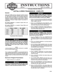
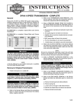
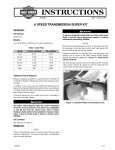
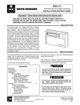
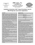
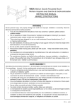
INSTRUCTIONS
®
-J03005
REV. 01-14-2004
Kit Numbers 33104-03, 33105-03
SOFTAIL 6 SPEED TRANSMISSION - COMPLETE
General
These kits fit 1990 to 1999 Softail model motorcycles. The
chrome side door included in this kit is machined to accept
the speedometer sensor.
Kit number 33104-03 is a complete 6 speed black and
chrome transmission.
Kit number 33105-03 is a complete 6 speed silver and
chrome transmission.
1st
2 nd
3 rd
4 th
5 th
6 th
STOCK 5 - SPEED
3.210
2.209
1.572
1.226
1.000
NA
SE 6 - SPEED
3.210
2.209
1.572
1.226
1.000
0.885
Transmission Ratio Comparison
1WARNING
The rider's safety depends upon the correct installation
of this kit. If the procedure is not within your capabilities
or you do not have the correct tools, have your HarleyDavidson dealer perform the installation. Improper
installation of this kit could result in death or serious
injury. (00308a)
NOTE
A Service Manual for your model motorcycle is available
from any Harley-Davidson dealer.
Removal of Original Transmission
1. Position motorcycle on a suitable lift.
1WARNING
To prevent accidental vehicle start-up, which could
cause death or serious injury, disconnect battery cables
(negative (-) cable first) before proceeding. (00307a)
1WARNING
Disconnect negative (-) battery cable first. If positive (+)
cable should contact ground with negative (-) cable connected, the resulting sparks can cause a battery explosion,
which could result in death or serious injury. (00049a)
2. Refer to SEAT and BATTERY CABLES in the Service
Manual and follow the instructions given to remove the
seat and disconnect the battery cables, negative cable
first.
3. See the TRANSMISSION CASE REMOVAL in the
Service Manual and follow the instructions given to
remove of the transmission case.
4. Refer to the PRIMARY CHAINCASE REMOVAL section
in the Service Manual and follow the instructions given
to remove the primary chaincase cover.
1WARNING
Always wear proper eye protection when removing or
installing retaining rings. Use the correct retaining ring
pliers. Verify that the tips of the pliers are not excessively worn or damaged. Slippage may propel the ring with
enough force to cause an accident. This could result in
death or serious injury.
5. Refer to PRIMARY CHAINCASE REMOVAL in the
Service Manual and follow the instructions given to
remove the primary drive assembly.
6. See the STARTER REMOVAL section in the Service
Manual and follow the instructions given to remove the the
starter, neutral switch connection and speedometer sensor.
7. See the VEHICLE SPEED SENSOR section and unplug
the vehicle speedometer sensor connection and remove
the mounting bolt. Lift sensor from the transmission
case (if equipped) and set aside.
8. Refer to NEUTRAL SWITCH in Service Manual and disconnect the connectors from the neutral switch.
9. Refer to PRIMARY CHAINCASE in the Service Manual
and follow the instructions given to remove the primary
chaincase housing.
10. Refer to the EXHAUST SYSTEM section in the Service
Manual and follow the instructions given to remove the
exhaust.
11. Loosen but, do not remove rear axle to relieve drive belt
tension.
12. Refer to OIL TANK REMOVAL in the Service Manual
and follow the instructions given to drain, and remove
the oil tank, and detach the vent, feed and return lines.
13. Refer to CLUTCH CONTROL in the Service Manual
and follow the instructions given to remove the clutch
cover and disconnect the clutch cable end from the
cover. Set the cable aside for later re-installation.
14. Remove transmission mounting hardware from the
transmission mounting plate on the frame.
15. The transmission is now loose from the frame and
engine and resting on a support.
16. Slide the transmission out the right side of the motorcycle frame.
1 of 4
i06179a
Switch
stud
O-ring
Mounting studs
Figure 1.Transmission Housing to Frame Mounting
Plate Sequence
Installation of New Transmission
1. Refer to the Service Manual and install the new transmission into the motorcycle. Slide the transmission from
the right and align the mounting bolt holes on the transmission with the mounting plate holes on the frame.
2. See Figure 1. Install the five nuts and washers hardware removed in step 12. Tighten the five transmission
mounting nuts to 33-38 ft-lbs (45-52 Nm).
3. Refer to the Service Manual TRANSMISSION ADJUSTMENT and follow the instructions given to adjust transmission.
4. Refer to Service Manual REAR BELT and SPROCKETS
and follow the instructions given to install the belt on the
transmission.
5. Refer to PRIMARY CHAINCASE HOUSING in the
Service Manual to install the chaincase housing.
6. See the DRIVE COMPONENTS section in the Service
Manual and install the clutch assembly, primary chain
and compensating sprocket as a single assembly.
7. Refer to VEHICLE SPEED SENSOR in the Service
Manual and install the vehicle speed sensor, with the
new o-ring (89) included in the kit.
NOTE
If the vehicle is not equipped with a Vehicle Speed Sensor,
install the speed sensor plug (108) with the o-ring (89) and
screw (90).
8. Refer to NEUTRAL SWITCH section in the Service Manual
and connect the neutral switch. See Figure 2. For 1990 thru
1997 model years, refer to the wiring diagram. The wiring
harness for these years will have a single cap connector (HD part number 9905) connected to the Neutral Switch.
Replacement of the single cap connector will need to be
performed as follows:
a. Cut the single wire cap off the stock wire.
b. Connect the supplied wire part number 72405-98T
(59) to the cut wire, with the supplied connector part
number 70585-93 (87) and attach onto either pole of
the Neutral Switch.
c. Attach the other supplied new wire part number
72405-98BK (100) to the remaining pole.
Figure 2. Neutral Switch
7. Refer to the STARTER INSTALLATION section in the
Service Manual and follow instruction given to install the
starter from the right side of the motorcycle.
8. See the OIL TANK section in the Service Manual and
follow the instructions given to install the oil tank and
attach the vent, feed and return lines.
CLUTCH RELEASE COVER ASSEMBLY
9. Refer to TRANSMISSION CLUTCH RELEASE COVER in
the Service Manual and remove and disassemble the new
clutch release cover to reconnect the clutch cable.
10. Refer to CLUTCH CONTROL INSTALLATION in the
Service Manual and follow the instructions given to
assemble the clutch release cover with the cable reconnected.
11. See the EXHAUST SYSTEM section in the Service
Manual and follow the instructions given to install the
complete exhaust with heat shields.
12. Add Harley-Davidson lubricants to the transmission, oil
tank and primary. See the oil grades and capacities listed in the service manual for your motorcycle model.
1WARNING
Connect positive (+) battery cable first. If positive (+) cable
should contact ground with negative (-) cable connected,
the resulting sparks can cause a battery explosion, which
could result in death or serious injury. (00068a)
13. Refer to the Service Manual, and follow instructions
given to reconnect the battery cables, positive cable first
and install the seat.
1WARNING
After installing seat, pull upward on front of seat to be
sure it is in locked position. While riding, a loose seat
can shift causing loss of control, which could result in
death or serious injury. (00070a)
TRANSMISSION SERVICE
14. Replace Transmission fluid after the first 500 miles.
Refer to the Service Manual and follow the instructions
for the proper subsequent service intervals.
d. Attach the supplied eyelet part number 72241-94A
(86) to the other end of the new wire and attach to a
convenient grounding location.
-J03005
2 of 4
®
i04337b
Part No. 33104-03, 33105-03
Service Parts
Date 01/04
Softail 6 Speed Transmission - Complete
102, 103
i06180
90
62
47
48
40
108
25
52
54 56 53
55
20 74
22 21
89
12
49
5
13
10 4
8
7
26
6
27
26
26 27 26
34
11
1
24
74
76
61
2
88 35 75
24
80
19
19
19
58
26
43
22
20 21
76
9
49
42
8
13
3
10 4
26 26 26 19 19
57
14
Item
1
2
3
4
5
6
7
8
9
10
11
12
13
14
16
17
18
19
20
21
22
24
25
26
Description (Qty)
Mainshaft
Countershaft
Countershaft 1st Gear
Mainshaft 3rd Gear/
Countershaft 2nd Gear (2)
Mainshaft 4th Gear
Mainshaft 6th Gear
Mainshaft 1st Gear
Countershaft 3rd Gear/
Mainshaft 2nd Gear (2)
Countershaft 4th Gear
Shift Ring, 1-2, 3-4 (2)
Shift Ring, 5-6
Side Door
Splined Sleeve (2)
Shifter Fork Shaft
Shifter Fork, 1-2 1
Shifter Fork, 3-4 1
Shifter Fork, 5-6 1
Split Cage Bearing (5)
Side Door Bearing
Retaining Ring (2)
Side Door Bearing (2)
Mainshaft/Countershaft
Locknut (2)
Clutch Release Cover
Lower Screw (4)
Thrust Washer (2)
Retaining Ring (8)
-J03005
Part No.
35058-03
35059-03
35080-03
35083-03
35104-03
35131-03
35134-03
35135-03
35136-03
35137-03
35138-03
35139-03
35140-03
34088-87A
35143-03
35144-03
35145-03
8876A
35087-99
8992A
35078-79
4718A
37313-80
11067
Item
27
32
34
35
39
42
43
44
47
48
49
52
53
54
55
56
57
58
61
62
74
75
76
80
88
89
90
108
17
16
18
Description (Qty)
Mainshaft Thrust Washer (2)
Quad Seal
Main Drive Gear
Clutch Cable Coupler
Shifter Seal Washer
Side Door Gasket
Clutch Release Cover Gasket
Lid Gasket
Pushrod Bearing
Right Clutch Pushrod
Upper Side Door & Top Lid
Screw (3)
Clutch Release Cover
Ramp Retaining Ring
Inner Ramp
Outer Ramp
Ramp Ball Bearings (3)
Dipstick
Dipstick O-Ring
Clutch Release Cover
Upper Screw & Lid (3)
Pushrod Retaining Ring
Bottom Door Bolts (2)
Shifter Fork Shaft Set Screw
Lower Side Door Screw (2)
Countershaft 5th Gear
Drain Plug, 1990-99 FXST
Speed Sensor O-Ring
Speed Sensor Plate Screw (2)
Speed Sensor Plug
Part No.
6003
11165
35237-03
34920-86A
6497HW
35147-03
35148-03
34904-86D
37312-75
35149-03
4814A
35157-03
10998
25604-00
25605-00
8873
37075-87
11132
4717A
11096
3300
3784
3249
35238-03
739A
11289A
3594
35239-03
3 of 4
®
Part No. 33104-03, 33105-03
Service Parts
Date 01/04
Softail 6 Speed Transmission - Complete
i06180a
64
99
98
50
90
70
69
68
67
29
41
91
36 78
66
79
50
72
73
45 46
87 86
81
82
83
84
85
32
51 39
71
50
65 66
30 28
101
59
50
37
100
23
38
33
61
44
60
Item
23
28
29
30
33
36
37
38
40
41
45
46
50
51
59
60
64
65
66
67
68
69
Description (Qty)
Top Lid Vent Hose
Sprocket Spacer
Mainshaft Inner Race
Large Oil Seal
Top Lid Vent Fitting
Speed Sensor Plate
Neutral Switch
Top Lid, Chrome
Pushrod Center
Countershaft Bearing
Shifter Seal
Shifter Retaining Ring
Pillow Block Screw (4)
Shifter Centering Screw
Black Wire Assembly
Top Lid Screw (4)
Transmission Pulley
Mega Nut
Mega Nut Screw (2)
Shift Drum w/ Pins
Shift Drum Pin (6)
Left Pillow Block Assembly
-J03005
Part No.
42533-91A
33344-94
34091-85A
12067B
62375-57A
35153-03
33904-00
34541-00
37088-85
8977
12045
11150
3909
34978-00A
72405-98BK
4740A
40250-94C
35236-03
4069A
35142-03
33385-02
33301-00A
Item
70
71
72
73
78
79
81
82
83
84
85
86
87
91
98
99
100
101
101
102
103
Description (Qty)
Shift Drum Retainer
Door Roll Pin
Shifter Lever
Shifter Lever Screw
Speed Sensor Plate Gasket
Sleeve
Right Pillow Block Assembly
Detent Arm Screw
Detent Arm Spring
Detent Sleeve
Detent Follower
Terminal (1/4 inch ring)
Connector
Shifter Shaft Assembly
Bearing Retaining Ring
Main Drive Gear Bearing
Tan Wire Assembly
Transmission Case, Black
Transmission Case, Silver
Transmission Complete (Silver)
Transmission Complete (Black)
Part No.
11342
634
33849-97
856A
35152-03
34979-00
33304-00
33376-00
33374-00
33375-00A
33364-00A
72241-94A
70585-93
35146-03
11161
8996A
72405-98TN
35833-03
35835-03
33104-03
33105-03
4 of 4