1
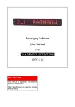
S&S Cycle, Inc.
®
Instruction 51-1232
7-12-07
Copyright
©
235 Causeway Blvd.
La Crosse, Wisconsin 54603
2006, 2007
by S&S Cycle, Inc.
Phone: 608-627-1497 • Fax: 608-627-1488
All rights reserved.
Printed in the U.S.A.
Technical Service Phone: 608-627-TECH (8324)
Technical Service Email: [email protected]
Website: www.sscycle.com
Because every industry has a leader
Installation Instructions for S&S® All-Helical Transmission
Gear Set Cassettes for Harley-Davidson® 1991-’05 DynaTM,
1991-’06 FLT and Softail® models, and Custom Applications
DISCLAIMER:
IMPORTANT NOTICE:
S&S parts are designed for high performance, off road, racing
applications and are intended for the very experienced rider only. The
installation of S&S parts may void or adversely effect your factory
warranty. In addition such installation and use may violate certain
federal, state, and local laws, rules and ordinances as well as other laws
when used on motor vehicles used on public highways, especially in
states where pollution laws may apply. Always check federal, state, and
local laws before modifying your motorcycle. It is the sole and exclusive
responsibility of the user to determine the suitability of the product for
his or her use, and the user shall assume all legal, personal injury risk and
liability and all other obligations, duties, and risks associated therewith.
Statements in this instruction sheet preceded by the following words
are of special significance.
The words Harley®, Harley-Davidson®, H-D®, Sportster®, Evolution®, and
all H-D part numbers and model designations are used in reference only.
S&S Cycle is not associated with Harley-Davidson, Inc.
SAFE INSTALLATION AND OPERATION RULES:
Before installing your new S&S part it is your responsibility to read and
follow the installation and maintenance procedures in these
instructions and follow the basic rules below for your personal safety.
● Gasoline is extremely flammable and explosive under certain
conditions and toxic when breathed. Do not smoke. Perform
installation in a well ventilated area away from open flames or sparks.
● If motorcycle has been running, wait until engine and exhaust pipes
have cooled down to avoid getting burned before performing any
installation steps.
● Before performing any installation steps disconnect battery to
eliminate potential sparks and inadvertent engagement of starter while
working on electrical components.
● Read instructions thoroughly and carefully so all procedures are
completely understood before performing any installation steps.
Contact S&S with any questions you may have if any steps are unclear
or any abnormalities occur during installation or operation of
motorcycle with a S&S part on it.
WARNING
Means there is the possibility of injury to yourself or others.
CAUTION
Means there is the possibility of damage to the part or motorcycle.
NOTE
Other information of particular importance has been placed in italic type.
S&S recommends you take special notice of these items.
WARRANTY:
All S&S parts are guaranteed to the original purchaser to be free of
manufacturing defects in materials and workmanship for a period of
twelve (12) months from the date of purchase. Merchandise that fails
to conform to these conditions will be repaired or replaced at S&S’s
option if the parts are returned to us by the purchaser within the 12
month warranty period or within 10 days thereafter.
In the event warranty service is required, the original purchaser must
call or write S&S immediately with the problem. Some problems can be
rectified by a telephone call and need no further course of action.
A part that is suspect of being defective must not be replaced by a
Dealer without prior authorization from S&S. If it is deemed necessary
for S&S to make an evaluation to determine whether the part was
defective, a return authorization number must be obtained from S&S.
The parts must be packaged properly so as to not cause further damage
and be returned prepaid to S&S with a copy of the original invoice of
purchase and a detailed letter outlining the nature of the problem, how
the part was used and the circumstances at the time of failure. If after
an evaluation has been made by S&S and the part was found to be
defective, repair, replacement or refund will be granted.
ADDITIONAL WARRANTY PROVISIONS:
● Consult an appropriate service manual for your motorcycle for correct
disassembly and reassembly procedures for any parts that need to be
removed to facilitate installation.
(1) S&S shall have no obligation in the event an S&S part is modified by
any other person or organization.
● Use good judgement when performing installation and operating
motorcycle. Good judgement begins with a clear head. Don't let
alcohol, drugs or fatigue impair your judgement. Start installation
when you are fresh.
(2) S&S shall have no obligation if an S&S part becomes defective in
whole or in part as a result of improper installation, improper
maintenance, improper use, abnormal operation, or any other misuse
or mistreatment of the S&S part.
● Be sure all federal, state and local laws are obeyed with the
installation.
● For optimum performance and safety and to minimize potential
damage to carb or other components, use all mounting hardware that
is provided and follow all installation instructions.
(3) S&S shall not be liable for any consequential or incidental damages
resulting from the failure of an S&S part, the breach of any warranties,
the failure to deliver, delay in delivery, delivery in non-conforming
condition, or for any other breach of contract or duty between S&S and
a customer.
● Motorcycle exhaust fumes are toxic and poisonous and must not
be breathed. Run motorcycle in a well ventilated area where fumes
can dissipate.
(4) S&S parts are designed exclusively for use in Harley-Davidson® and
other American v-twin motorcycles. S&S shall have no warranty or
liability obligation if an S&S part is used in any other application.
1
S&S® Cycle Cassette Assembly Installation Instructions
SPECIAL TOOL REQUIREMENTS
● Inner Primary Bearing Race Puller, S&S PN 56-5141
● Inner Primary Bearing Race Installer, S&S PN 56-5145
● Main Drive Gear Remover/Installer & Bearing Installer
● Primary Drive Locking Tool
● Mainshaft Locknut Wrench
● Output Sprocket Locking Tool
● Shift Shaft Sleeve Remover/Installer
CASSETTE CONTENTS
For more information see exploded view on pages 14-15.
ADDITIONAL PARTS REQUIRED
● FLT models will require Oil Filler Spacer Kit, S&S PN 56-1292, See Picture 32
● 1991-’97 H-D® models will require H-D #72405-98TN and H-D #72405-98BK to adapt from a one-wire neutral switch to a two-wire switch
● Clutch Center Pushrod H-D #37088-90, if installation is for new construction (not required for replacing existing stock H-D transmission)
OPTIONAL PARTS
● S&S Inner Primary Bearing Race PN 56-5089, See Picture 28
● S&S Hydraulic Side Cover PN 56-4060
● S&S Speedometer Calibrator PN 55-1007
Cassette Assembly 56-1222 for FLT & Softail®
Cassette Assembly 56-1255 for DynaTM & Softail®
The S&S® six-speed gear sets are available for stock transmission cases of 1991-’05 Harley-Davidson® DynaTM, 1991-’06 FLT and Softail®
models—as well as similar aftermarket transmission cases, clearancing is required. If you are not comfortable modifying your
transmission case—or do not have the proper tools to change bearings and remove the clutch assembly—contact the S&S tech line at
(608) 627-TECH for a dealer recommendation.
NOTE:
● Trap doors are machined different for specific applications.
● S&S PN 56-1255 is intended for 1991-’05 Dyna models and 1991-’99 Softail models with tab for exhaust and starter mounting
brackets.
● S&S PN 56-1222 is intended for 1991-’06 FLT models and 2000-’06 Softail models without the mounting tab on the trap door.
2
WARNING
The safety of the motorcycle rider is dependent on proper installation of this product. If you are not certain of your capabilities
or do not have the correct tools for this installation, please consult a shop to have it done. Improper installation of this product
could result in injury or death to the rider.
WARNING
Be sure to disconnect the battery of your motorcycle before starting on this procedure. Accidental starting of the motorcycle
could cause injury to you or others around you during the installation.
CAUTION
To avoid damage to motorcycle and installed parts follow the guidelines in your factory service manual when taking the
transmission and primary assemblies of your motorcycle apart.
DISASSEMBLY
1.
Disconnect the negative cable from the battery.
2.
Drain primary and transmission fluids.
3.
Follow the guidelines in your factory service manual to remove the entire primary assembly. The cover, primary chain, clutch
and compensating sprocket components need to be removed. Additionally the starter, jackshaft and inner primary will need to
come off.
4.
Remove any exhaust components that restrict access to the transmission side door.
5.
On FLT models, the oil filler spout will also be removed at this time. NOTE: Mask opening in case to prevent debris from entering
oil tank. See Picture 2.
6.
Remove clutch release cover and clutch cable.
7.
Remove the neutral switch and transmission top cover. NOTE: Harley-Davidson® DynaTM models will require masking on the front
of the transmission case to prevent debris from entering the oil tank and oiling system. See Picture 3.
8.
Remove the shift drum and support blocks.
9.
Remove the shift shaft and forks.
10. Use an inner bearing race removal tool (S&S® tool PN 56-5141) to remove the race from the transmission mainshaft.
11. After removing the transmission side door hardware, slide the gear set from the transmission case.
12. Remove the shifter shaft assembly and seal.
13. Consult your factory manual for the procedure necessary to remove the main drive gear and bearing.
14. Remove the countershaft needle bearing following the directions in your factory service manual.
CAUTION
Small metal chips and pieces can damage machined surfaces and block passageways. Be sure to thoroughly clean all metal chips
and pieces out to prevent premature failures.
WARNING
Always wear eye protection while grinding and cleaning the transmission case to avoid eye injury.
3
5-STEP MODIFICATION
1.
3-4 Shift Fork Clearance
2.
Shift Linkage Clearance
3.
First Gear Clearance
4.
5-6 Shift Fork Clearance
5.
Clean Up
1. 3-4 Shift Fork Clearance
Due to the multiple transmission cases that the S&S® cassette fits, clearance will be required in several locations to facilitate a
successful installation. See Picture 1 below for required clearance locations. As always, be sure to verify proper clearance has been
created by mocking-up the affected components.
5-6 shift fork clearance.
Shift lever clearance.
3-4 shift fork clearance.
Countershaft 1st gear clearance.
Picture 1
A.
B.
4
You will need to use tape to cover all of the transmission side door holes except the top two, these will be used to support
the clearance template in step 3.
Use tape to cover the following components: speed sensor and screw holes, top cover and shift drum support block screw
holes, fluid drain hole, shifter shaft bore, main drive gear opening, countershaft needle bearing bore and the fork shaft bore.
Installation on FLT models must seal off the oil filler spacer with tape. See Picture 2. Installation on Harley-Davidson® DynaTM
models will require sealing off the oil tank cavity at the top cover surface. See Picture 3.
Picture 2
Picture 3
C.
Position the clearance template on the side door uncovered holes using two 1⁄4 x 20 x 1” screws with the words THIS SIDE
OUT facing you as shown in Picture 5. Position the template so that it is flush with the top edge of the transmission
housing. Use a scribe or fine-tip marking pen to trace the outline of the guide and then remove the template.
Flush with this surface.
Picture 4
D.
E.
Picture 5
Spread out a few shop rags to catch any metal shavings that fall during the clearancing process.
Drill the shaft hole out with increasingly larger drill bits until you get to 5⁄8” or 3⁄4”. Now use an air-powered grinder to remove
the rest of the material in the marked area. See Picture 6. Take your time and make sure that you remove the material evenly
across the front of the case. It is common to remove more material on the surface closest to you and have the cut dip down
a little in the back—do not allow this to happen.
NOTE: Use a combination square or equivalent to insure that the material removal is square to the gasket surface. The square
should only touch the inside of the case at the material closest to the gasket surface. See Picture 7.
Ideal clearancing should be
perpendicular to gasket surface.
Picture 6
Picture 7
5
F.
Use a deburring tool, file or sandpaper to remove any rough edges or chips from the clearanced area as illustrated in Picture 8.
Picture 8
2. Shift Linkage Clearance
A.
Remove shift shaft sleeve by using remover tool H-D® #35156-03 to drive the original sleeve out of the transmission
case. See Picture 9.
Picture 9
6
B.
Follow the guidelines in your factory service manual to install the sleeve in the shifter shaft bore. NOTE: The new S&S® 1.480”
sleeve is a special length for the S&S® transmission, so when you use the remover tool H-D® #35156-03, you will need to install
a spacer of approximately 1⁄2” to the tool set. See Picture 10.
1) Install the shift-shaft sleeve as follows: Place the S&S® 1.480” sleeve over the installer. Next, slide a thrust washer, thrust
bearing and the second thrust washer onto the installer screw— add 1⁄2” of spacer material (Picture 10).
2) Use engine oil to lubricate the outside of the new sleeve, inside and outside of the installer threads and the inside of the
transmission case sleeve bore. Also lube the thrust washers and bearing.
Sleeve Installer
⁄2” Spacer
1
Installer Screw
Thrust Washers & Bearing
Picture 10
3)
Position the S&S® sleeve and installer against the bore inside the transmission case. From the outside of the case, thread
the installer screw in—making sure to keep the sleeve properly aligned as illustrated in Picture 11.
Picture 11
7
4)
5)
6)
7)
8)
Tighten the installer until the sleeve stops against the thrust washer. Remove the installation tool and verify the sleeve is
flush with the counter-bore surface on the outside of the case.
Lubricate the inside of the sleeve and the outside of the new S&S shifter shaft pawl. Slide the new shifter shaft pawl into
the sleeve. See Picture 12.
Verify that the shift pawl has full rotation.
If there is interference, grind the case surface until the shift pawl sweeps without binding. See Picture 12.
When the appropriate clearance has been verified, slide the shifter shaft pawl into the case from the inside and install
the new shifter shaft seal, washer, retaining ring and shift linkage from outside the case.
Common location for shift pawl interference.
Picture 12
NOTE: If shift shaft retaining ring groove is not in the appropriate location, something is wrong. Verify that the 1.480" sleeve was
installed flush with the bottom of the seal counterbore surface.
3. First Gear Clearance
A.
B.
Measure and mark on the inside bottom of the case at 1.250” and 2.200” from the trap door gasket surface in-line with the
countershaft. This is where first gear or the largest gear is located. See Picture 13.
Use a die grinder to blend the transition in the case casting by removing approximately .050” of material. See Picture 14.
Picture 13
8
Picture 14
4. 5-6 Shift Fork Clearance
Some FLT models will require clearance for the 5-6 shift fork as indicated in Picture 20.
A.
Insert the 5-6 shift fork and shift shaft into the case.
B.
Starting in the center of the shift shaft, sweep the fork toward the back of the case until it contacts the inside of the case.
C.
Slide the fork toward the main drive gear bearing bore and note the material that pushes the fork toward the front of the
case. This material will need to be removed with a die grinder to obtain proper clearance as shown in Picture 20.
D.
Remove the interfering material from the transmission case.
5. Clean Up
WARNING
Always wear eye protection while grinding and cleaning the transmission case to avoid eye injury.
A.
Remove the shop rags. Use a shop vacuum to remove any remaining large chips as shown in Picture 15. Once the case is clean,
use spray solvent and compressed air (Picture 16) to remove remaining particles.
Picture 15
B.
Picture 16
Remove the masking tape from all of the passages and holes except the oil filler on FLT models and the top cover oil tank
cavity on Harley-Davidson® DynaTM models. Use compressed air and spray solvent necessary to remove any remaining chips
or debris before beginning installation.
9
INSTALLATION
WARNING
The safety of the motorcycle rider is dependent on proper installation of this product. If you are not certain of your capabilities
or do not have the correct tools for this installation, please consult a shop to have it done. Improper installation of this product
could result in injury or death to the rider.
1.
Install the provided S&S® shift pawl centering screw (PN 56-1002 adjuster, PN 50-5044 nut) as shown in bottom of Picture 17. It is
eccentric to allow more precise adjustments. Install adjuster to approximately .525” from outer casting surface. Be sure that pawl
centering adjuster is installed far enough to limit the sweeping of the shift pawl arm when upshifting and downshifting.
Remove stock Harley-Davidson® 2000-later fixed centering screw.
Install S&S adjustable shift pawl centering screw.
Install this surface to .525” from machined surface of case.
Picture 17
2.
Start the installation by applying clean transmission fluid to all the bearings and shafts prior to putting them in.
3.
You will need to follow the appropriate Harley-Davidson® factory service manual to install the new countershaft needle bearing
PN 56-3031 flush with the outside of the transmission case and the S&S® main drive gear bearing PN 56-1280 and gear PN 56-5123
as shown in Picture 18.
Picture 18
10
4.
Align and install the S&S® shift forks and shaft on the gearset. The largest shift fork (3-4) is installed closest to the transmission
door. Next, the small-notch fork (1-2) rides in the center and the flat notch fork (5-6) is installed closest to the primary as
shown below. Note the direction of shift shaft installation shown below.
3-4
1-2
5-6
Stepped-end
of shift shaft
Picture 19
CAUTION
Do not use bolts to draw trap door onto case. This may strip the case threads.
5.
Install the provided gasket on the transmission side door surface. Slide the gear set into place as one piece. You may need to rotate
the main drive gear to mesh with the countershaft gear and lightly tap the transmission door with a rubber mallet to seat it
completely over the alignment dowels. Install the supplied hardware—but do not put any threadlock on them at this time. There
are six fasteners, the top two are 1⁄4”-20 X 1.25” long and the bottom four are 5⁄16-18 X 1.25” long. Each chrome fastener has a
corresponding flat washer for installation.
6.
Rotate main shaft to verify that there is no interference between the gears and the transmission case. If the mainshaft does not
rotate freely, determine the cause and correct the interference before moving on.
7.
Check for adequate clearance between the shift fork (5-6) and the case area closest to the primary (Picture 20). This can be done
by sweeping the fork and collar into the adjacent gears, while using a .030" feeler gauge.
Picture 20
11
8.
Verify the clearance between the 3-4 shift fork and the modified portion of the case is a minimum of .030" to allow full travel of
the shift fork (Picture 21). If there is not enough clearance make sure to remove the cassette and cover all the bearings and surfaces
again—before removing any material. Do not skip this operation as premature wear or failure could result from chips getting
caught in the transmission.
Verify .030" clearance between shift fork and case.
Picture 21
9.
Install the transmission drain plug 14-18 ft-lbs. Install 1⁄2”-20 set-screw in trap door on the end of the shift rail using blue threadlock,
do not tighten all the way, shift rail should be free to rotate with very little endplay.
10. Place the new S&S® shift drum and cast pillow blocks on the top dowels. See Picture 22. Apply blue threadlock on the new S&S
hardware and torque to 7-9 ft-lbs. The four fasteners supplied are 1⁄4”-20 X 1.25” black oxide coated. They should be installed with
the supplied lock washers. See Picture 26.
Picture 22
11. Adjust the shifter pawl by selecting third gear. Next, rotate the centering screw adjuster with a 1⁄4” wrench until the pawl is centered
between the shift drum pins (Picture 23). Verify the adjustment by sweeping the shift lever in an up- and down-shift direction until
the pawl arm engages the pins on the shift drum. Do not rotate the shift drum. Once equal clearance is achieved upshifting and
downshifting, tighten the adjuster locknut to 20 ft-lbs and verify that the pawl is still centered. See Picture 24.
Adjuster locknut
Adjust pawl to achieve equal clearance.
Picture 23
12
Picture 24
NOTE: Due to a stack-up of tolerance in transmission cases that are machined by other manufacturers, it may be necessary to manually
adjust the shift pawl linkage to prevent shift pawl from contacting the drum or the housing for the drum bearing support.
12. Shift pawl to shift drum and shift pawl to drum bearing support clearance:
a.
b.
c.
Sweep shift arm in an upshift direction and measure the clearance to the shift drum using a feeler gauge while pressing in on
the end of the shift shaft. It does not matter what gear is selected.
Measure the clearance on the opposite side of the shift arm to the bearing support using a feeler gauge while pulling out on
the shift arm.
If the clearance on both sides of shift arm is greater than .020”, no adjustment is required, move on to step 13. If either
clearance is less than .020”, move on to step d.
NOTE: A centered shift arm with little endplay will yield .040” clearance on both sides of the shift arm. Excessive endplay in shift arm
can be reduced by pressing the shift shaft sleeve toward the gearset. Endplay of shift arm should be a maximum of .020”.
d.
Adjust shift pawl clearance by removing the spring from the shift pawl arm to allow free movement. Rotate pawl arm to
vertical and push arm in or out to achieve equal clearance to shift drum and bearing support. Repeat steps a-c until
appropriate clearance is achieved. See Pictur e 25 and 26.
Insert feeler gauge as
shown by arrows. Minimum
clearance of .020" per side.
Adjust the clearance by bending shift
arm in or out as shown by arrows.
Picture 25
Manual adjustment.
Picture 26
13. Rotate the transmission by hand, shifting through all six gears to ensure there is no binding.
14. Once it has been verified that the transmission shifts properly and adequate clearance has been achieved remove and reinstall the
side-door fasteners using blue threadlock. Torque the 5⁄16” fasteners to 13-16 ft-lbs and the 1⁄4” to 7-10 ft-lbs.
NOTE: Harley-Davidson® DynaTM models will require use of stock stud fasteners for exhaust bracket. FLT models will require installation of
exhaust bracket at this time.
15. Install main drive gear seal PN 56-3033, slide the O-ring over the main drive gear splines until it contacts the inner bearing race of
the S&S main drive gear bearing. Follow the o-ring with the sprocket spacer PN 56-1293 by sliding it onto the main drive gear splines.
16. Install a new inner bearing race onto the transmission mainshaft—we recommend the S&S® bearing race PN 56-5089 (Picture 28)
to eliminate the problematic movement of the stock bearing race which can potentially destroy the output gear seal in high HP
applications.
S&S® Inner Bearing Race Installer shown, PN 56-5145
Optional S&S® Inner Bearing Race PN 56-5089
Picture 27
Picture 28
13
NOTE: It is important that you pay special attention to shift pawl adjustment. The adjustment of the shift pawl is directly related to
proper function and smoothness of shifting.
17. FLT and Harley-Davidson® Softail® Transmission Top Cover
Verify transmission top cover clearance to the shift pawl by using clay or machinists dye. Clearance as necessary. Then, install the
top transmission cover with the supplied gasket. Use blue threadlock on the screws and torque them to 7-9 ft-lbs. Rotate and shift
the transmission through all six gears again to confirm there is no binding.
NOTE: Stock top cover usually requires clearance operation to prevent shift linkage from binding. Use clay or machinists dye to identify
location of interference and correct the problem with a die grinder. Picture 29 illustrates a modified top cover for a FLT/Softail model.
Picture 29
Top cover clearance
for FLT/Softail model
1991-’98 Dyna Model Top Cover Hardware and Gasket Assembly.
When installing the S&S 6 speed transmission in 1991-’98 Dyna models, the supplied gaskets and hardware are required for shift
drum to top transmission cover clearance. Picture 30 illustrates supplied gaskets and hardware.
1-
234-
With the engine oil drained pull the dipstick cover out and place the 1.450” diameter gasket on the oil tank where the dipstick
cover pushes in. With the o-ring still in place on the dipstick cover push the dipstick cover back in the oil tank capturing the
gasket between the oil tank and the dipstick cover.
Now slide the supplied 1.170” diameter gasket over the top of the dipstick cover with the o-ring in place.
Install the new .120” thick transmission top cover gasket followed by the transmission top cover.
Install the supplied oil fill spout gasket followed by the oil fill spout. Picture 31 illustrates the assembly of gaskets that are
required for transmission top cover clearance.
NOTE: Verify transmission top cover clearance to shift detent arm and spring by using clay or machinist dye. Picture 32 illustrates the area
of the top cover that will be the closest. If clearance is required correct the problem area with a die grinder. Once clearance is verified
use blue threadlock on the supplied screws and torque to 7-9 ft-lbs. Picture 33 illustrates the assembly of the supplied hardware kit.
Top cover
clearance for
1991-’98 Dyna
model
Picture 32
Picture 30
14
Picture 31
Picture 33
18. Now install the new S&S neutral switch (3-5 ft-lbs) and speed sensor cover (6-8 ft-lbs) on the transmission case.
NOTE: 1991-’97 models have a single-wire neutral switch which will not work with the S&S two-wire switch. Changing to the two-wire
switch will require wiring harness part numbers: H-D #72405-98TN and H-D #72405-98BK.
Convert the wiring by following the procedure below:
a. Cut the existing single pin connector off and splice the tan wire in its place.
b. Connect the black and tan wires to the neutral switch. Attach the end of the black wire to a suitable ground using an eyelet
or equivalent solderless connector.
19. Slide the stock center pushrod in place, followed by the new S&S® throw-out bearing kit as shown in Picture 34. Lubricate ends of
pushrod and throw-out bearing PN 56-1229 with grease or gear oil.
Center clutch pushrod not included in kit.
Lubricate in locations shown.
Picture 34
NOTE: S&S does not supply the center clutch pushrod, H-D® #37088-90. It must be purchased separately for custom builds.
Approximately 10.750” in length.
20. Install new o-ring H-D #11140 and connect the speed sensor to the S&S® transmission door using the supplied 1⁄4"-20 X .625” long
button-head cap screw.
21. Pass the clutch cable through the new S&S side cover. Install the old ball ramp mechanism and put the snap ring in place. See
Picture 35. Put the new gasket on the door and install it with blue threadlock on the hardware. See Picture 36. There are six
fasteners, the top two are 2.75” long and the bottom four ar 1.750” long. Each fastener has a corresponding flat washer for
installation. Torque the 1⁄4-20 fasteners to 7-9 ft-lbs.
Picture 35
Picture 36
15
NOTE: If using S&S® hydraulic clutch side cover kit PN 56-4060 follow instructions included with the kit.
22. Fill the transmission with 20-24 ounces of 90 weight gear oil or equivalent.
NOTE: S&S offers an extension for the oil filler spout on FLT models—PN 56-1292 (not included in this kit). Be sure that the flat edge is
up, directed toward the transmission side cover as shown in Picture 37. This spacer will affect the oil level reading on the dipstick due
to the increased angle resulting from the additional spacing. Typically, the full level reading on your dipstick will be 1⁄4” to 3⁄8” below
normal. To verify what your new fill height will be follow the factory service manual procedures for changing your oil after installing
this transmission kit. You may want to put a notch on your dipstick indicating the new fill height.
Flat edge here.
Picture 37
23. Install exhaust system. Harley-Davidson® DynaTM models will require a clearance modification on the exhaust bracket as shown in
Pictures 38 & 39. This operation is required to clear the vehicle speed sensor boss.
NOTE: The S&S transmission gear set is .250” wider than a stock Harley-Davidson® unit. With that in mind, you may need to shim your
exhaust mounts to allow for the extra width.
24. Use a sprocket-locking tool and specialty deep socket to install the new lightweight 34-tooth S&S pulley and tighten/torque nut
to 50 ft-lbs using red threadlock and then turn the nut an additional 35-40 degrees. Install the lockplate and torque bolts/screws
with red threadlock to 7-9 ft-lbs. Never loosen the nut to align the lockplate holes. Use the 34-tooth final drive pulley on belt-drive
models 1991-’06.
Modify as shown by dotted line.
Install modified bracket with stock hardware as shown.
Fastener shown with hardware removed for demonstration purposes.
Picture 38
16
Picture 39
NOTE: Use of the stock 32-tooth pulley with the S&S® transmission will result in an extremely low overall first gear ratio. S&S provides
a 34-tooth pulley to counter-act the lower internal first gear ratio by changing the final drive ratio with the provided pulley.
Picture 40
25. Position the drive belt over the S&S 34-tooth pulley. This may require removing the rear axle to allow enough slack in the belt to
fit over the pulley.
a. Due to the increased diameter of the 34-tooth pulley, some inner primary housing’s may require a minor clearance cut on the
inner primary to allow for belt clearance in the area pointed out in Picture 41.
b. Mock fit and check clearance between drive belt and inner primary housing mounting boss. You should have at least .200” of
clearance between the whole width of the belt and the mounting boss when the belt is adjusted. See Picture 42. If there is
enough clearance move onto step 26. If material needs to be removed for added clearance, remove primary housing and start
with step 1 below.
1. Before removing any material tape up or remove bearings and seals to avoid any debris that could potentially cause
damage. Machine or grind away material to acquire .200” of clearance between belt and casting boss on the inner
primary housing. Use caution when grinding or machining that you don’t cut into the bolt hole. Clean thoroughly before
installing.
2. Repeat step 25b to verify clearance.
Belt
Picture 41
26. Assemble the primary drive following the factory manual
for your motorcycle. Also, fill primary with appropriate
amount of oil per your factory manual.
.200"
27. Adjust clutch cable per factory specification.
28. Connect battery cable and wipe down the vehicle.
29. Test drive motorcycle to verify clutch and transmission shift
pawl adjustments are appropriate.
Picture 42
30. Verify proper speedometer function and calibration. If you
do not have the parts to do this, you may want to purchase
an S&S Speedometer Calibrator PN 55-1007.
31. Verify proper neutral switch function.
17
REPLACEMENT PARTS
FOR S&S® 6-SPEED TRANSMISSIONS
3
48
21
20
42
49
2 & 43
3
3
3
14
2 24
9
17
15
16
30
18
2
19
7 & 46
39
1. Trap door, S&S 6-speed transmission
Harley-Davidson® 2000-’06 Softail®/ 1991-’06 FLT models .....56-1221
1991-’05 DynaTM, 1990-up FXR, 1991-’99 Softail .....................56-1253
2. Kit, gaskets and seals-1991-’06 Softail (S&S complete trans) ....56-1226
3. Hardware kit, 6-Speed transmission ........................................56-1227
4. Kit, ball and ramp, 6-speed transmission (18°) .......................56-1228
5. Kit, throwout bearing................................................................56-1229
6. Kit, speed sensor.........................................................................56-1230
7. Kit, bearings, thrust washers,
and retaining clips......................................................................56-1231
8. Mainshaft nut, jam hex nyloc, 3⁄4-16
UNF-2B (2 pack) .........................................................................56-1278
19. Ring, retaining beveled internal 3.346 ....................................50-8469
20. Cover, top-S&S complete transmission and cassette applications
Die cast
1991-’99 Softail & 1991-’00 FLT models ...................................56-5115
Billet
1999-’00 Dyna models................................................................56-1615
21. Switch, neutral............................................................................56-5113
22. Shaft, counter, S&S 6-speed, with integral main gear...........56-5114
23. Gear, fifth, countershaft, S&S 6-speed.....................................56-5116
24. Assembly, carrier, drum, LH .......................................................56-1294
25. Gear, second, countershaft, S&S 6-speed ................................56-5117
9. Kit, shift pawl, 6-speed transmission........................................56-1225
26. Gear, first, countershaft, S&S 6-speed......................................56-5118
10. Shift fork, 5-6 ..............................................................................56-1275
27. Gear, third/fourth, countershaft, S&S 6-speed........................56-3139
11. Shift fork, 1-2 ..............................................................................56-1276
28. Nut, bearing retainer, trap door, 115⁄16 - 20 UN-2B...................50-8477
12. Shift fork, 3-4 ..............................................................................56-1277
29. Collar, shift...................................................................................56-5149
13. Shaft, shift rail.............................................................................56-1274
30. Assembly, carrier, drum, RH.......................................................56-1295
14. Drum, shift...................................................................................56-1273
31. Sleeve, shift collar.......................................................................56-0010
15. Nut, hex 1 ⁄2 -24 UNS-2B LH ........................................................56-3003
32. Spacer, thrust, mainshaft, S&S 6-speed....................................56-1302
16. Sprocket, 34 tooth......................................................................56-5084
33. Gear, fourth, main, S&S 6-speed...............................................56-5126
17. Hardware, kit sprocket ..............................................................56-1272
34. Gear, third, mainshaft, S&S 6-speed.........................................56-5127
1
18
18. Spacer, sprocket ..........................................................................56-1293
CONTINUED...
Replacement Parts for S&S® 6-Speed Transmissions
35. Gear, first, mainshaft, S&S 6-speed .............................................56-5128
42. S&S inner primary bearing race- optional .................................56-5089
36. Gear, second, mainshaft, S&S 6-speed........................................56-5129
43. Gasket top cover (10 pack)
Softail®, FLT ....................................................................................56-5107
37. Gear, fifth, mainshaft, S&S 6-speed ............................................56-5131
1999-’05 Dyna™ ............................................................................55-1257
38. Gear, main drive, S&S 6-speed (with bearings and seal)...........56-5123
44. Gasket trap door (10 pack) ...........................................................56-5108
39. Case, transmission, S&S 6-speed—1991-’99 Harley-Davidson® Softail®
Natural............................................................................................56-1125
45. Gasket side cover (10 pack) ...........................................................56-5111
Black................................................................................................56-1126
46. Bearing, main drive gear .............................................................56-1280
Polished ..........................................................................................56-1127
47. Oil filler spacer kit- optional for FLT only (Not shown) ..............56-1292
40. Cover, side, S&S 6-speed transmission
48. Hardware kit, 1991-’98 Dyna.....................................................106-0850
Mechanically actuated..................................................................56-5120
49. Gasket kit, 1991-’98 Dyna ..........................................................106-0882
Hydraulically actuated..................................................................56-4060
41. Assembly, dipstick .......................................................................56-5132
9
7
10
22
11
12
23
13
25
1
31
7
28
38
29
2 & 44
26
3
3
27
2
6
29
31
8
2 & 45
41
37
5
36
3
4
40
35
3
34
31
29
33
32
7
19
TRANSMISSION SERVICE
NOTE: S&S recommends filling transmission with 20-24 ounces of 90 weight gear oil or equivalent.
1.
Perform an initial fluid change at 500 miles.
2.
Change fluid at 5,000 miles.
3.
Service transmission fluid every 5,000 miles thereafter.
Recommended Final Belt Drive Gearing
●
S&S recommends that you use a 32- or 34-tooth output pulley with a 65-tooth rear pulley.
●
S&S recommends the use of our 34-tooth output pulley with a 70-tooth rear pulley.
NOTE: Installation of the 34-tooth pulley should not require a belt change. Changing the rear pulley from a 70-to a 65-tooth will
require a belt change.
OVERALL GEAR RATIO CHART
GEAR RATIO CHART
Gear
S&S® Internal Transmission Ratio
Gear
S&S® 34T/70T
S&S 34T/65T
Stock 32T/70T
1st
3.882
1st
11.510
10.688
10.112
2nd
2.656
2nd
7.875
7.313
6.962
3rd
1.941
3rd
5.755
5.344
4.946
4th
1.475
4th
4.374
4.061
3.875
5th
1.179
5th
3.494
3.245
3.150
6th
1.000
6th
2.965
2.753
N/A
3308
3072
3515
RPM @ 80 MPH
in Top Gear
The chart on the right compares the overall ratios of the S&S six-speed transmission
with the supplied 34 tooth front sprocket and readily available 70 and 65 tooth rear
sprockets. Also shown for comparison are overall ratios for a stock 1995-up five-speed
transmission from a carbureted big twin with the stock 32 tooth front and 70 tooth
rear sprockets. Note that first gear is lower (higher ratio) with the S&S transmission
even with a 65 tooth rear sprocket. Also note the reduction in engine rpm at 80 mph
in top gear.
20