1
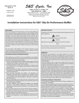
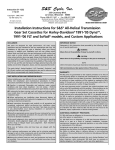
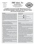
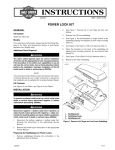
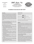
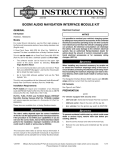
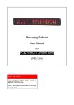
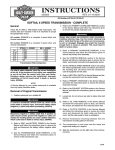
S&S Cycle, Inc.
®
Instruction 51-1198
5-23-07
Copyright © 2006, 2007
by S&S Cycle, Inc.
All rights reserved.
Printed in the U.S.A.
235 Causeway Blvd.
La Crosse, Wisconsin 54603
Phone: 608-627-1497 • Fax: 608-627-1488
Technical Service Phone: 608-627-TECH (8324)
Technical Service Email: [email protected]
Website: www.sscycle.com
Because every industry has a leader
Installation Instructions for S&S All-Helical Transmission
Complete Assembly for 1991-’99 Harley-Davidson®
Softail® and Custom Applications
DISCLAIMER:
IMPORTANT NOTICE:
S&S parts are designed for high performance, off road, racing
applications and are intended for the very experienced rider only. The
installation of S&S parts may void or adversely effect your factory
warranty. In addition such installation and use may violate certain
federal, state, and local laws, rules and ordinances as well as other laws
when used on motor vehicles used on public highways, especially in
states where pollution laws may apply. Always check federal, state, and
local laws before modifying your motorcycle. It is the sole and exclusive
responsibility of the user to determine the suitability of the product for
his or her use, and the user shall assume all legal, personal injury risk and
liability and all other obligations, duties, and risks associated therewith.
Statements in this instruction sheet preceded by the following words
are of special significance.
The words Harley®, Harley-Davidson®, H-D®, Sportster®, Evolution®, and
all H-D part numbers and model designations are used in reference only.
S&S Cycle is not associated with Harley-Davidson, Inc.
SAFE INSTALLATION AND OPERATION RULES:
Before installing your new S&S part it is your responsibility to read and
follow the installation and maintenance procedures in these
instructions and follow the basic rules below for your personal safety.
● Gasoline is extremely flammable and explosive under certain
conditions and toxic when breathed. Do not smoke. Perform
installation in a well ventilated area away from open flames or sparks.
● If motorcycle has been running, wait until engine and exhaust pipes
have cooled down to avoid getting burned before performing any
installation steps.
● Before performing any installation steps disconnect battery to
eliminate potential sparks and inadvertent engagement of starter while
working on electrical components.
● Read instructions thoroughly and carefully so all procedures are
completely understood before performing any installation steps.
Contact S&S with any questions you may have if any steps are unclear
or any abnormalities occur during installation or operation of
motorcycle with a S&S part on it.
WARNING
Means there is the possibility of injury to yourself or others.
CAUTION
Means there is the possibility of damage to the part or motorcycle.
NOTE
Other information of particular importance has been placed in italic type.
S&S recommends you take special notice of these items.
WARRANTY:
All S&S parts are guaranteed to the original purchaser to be free of
manufacturing defects in materials and workmanship for a period of
twelve (12) months from the date of purchase. Merchandise that fails
to conform to these conditions will be repaired or replaced at S&S’s
option if the parts are returned to us by the purchaser within the 12
month warranty period or within 10 days thereafter.
In the event warranty service is required, the original purchaser must
call or write S&S immediately with the problem. Some problems can be
rectified by a telephone call and need no further course of action.
A part that is suspect of being defective must not be replaced by a
Dealer without prior authorization from S&S. If it is deemed necessary
for S&S to make an evaluation to determine whether the part was
defective, a return authorization number must be obtained from S&S.
The parts must be packaged properly so as to not cause further damage
and be returned prepaid to S&S with a copy of the original invoice of
purchase and a detailed letter outlining the nature of the problem, how
the part was used and the circumstances at the time of failure. If after
an evaluation has been made by S&S and the part was found to be
defective, repair, replacement or refund will be granted.
ADDITIONAL WARRANTY PROVISIONS:
● Consult an appropriate service manual for your motorcycle for correct
disassembly and reassembly procedures for any parts that need to be
removed to facilitate installation.
(1) S&S shall have no obligation in the event an S&S part is modified by
any other person or organization.
● Use good judgement when performing installation and operating
motorcycle. Good judgement begins with a clear head. Don't let
alcohol, drugs or fatigue impair your judgement. Start installation
when you are fresh.
(2) S&S shall have no obligation if an S&S part becomes defective in
whole or in part as a result of improper installation, improper
maintenance, improper use, abnormal operation, or any other misuse
or mistreatment of the S&S part.
● Be sure all federal, state and local laws are obeyed with the
installation.
● For optimum performance and safety and to minimize potential
damage to carb or other components, use all mounting hardware that
is provided and follow all installation instructions.
(3) S&S shall not be liable for any consequential or incidental damages
resulting from the failure of an S&S part, the breach of any warranties,
the failure to deliver, delay in delivery, delivery in non-conforming
condition, or for any other breach of contract or duty between S&S and
a customer.
● Motorcycle exhaust fumes are toxic and poisonous and must not
be breathed. Run motorcycle in a well ventilated area where fumes
can dissipate.
(4) S&S parts are designed exclusively for use in Harley-Davidson® and
other American v-twin motorcycles. S&S shall have no warranty or
liability obligation if an S&S part is used in any other application.
1
REPLACEMENT PARTS
FOR S&S® 6-SPEED TRANSMISSIONS
3
21
20
2
3
3
14
15
3
2
9
24
30
17
18
16
2
19
7
39
1. Trap Door, 6-Speed Transmission ........................................56-1221
18. Spacer, sprocket ....................................................................56-1293
2. Kit, Gaskets and Seals...........................................................56-1226
19. Ring, retaining beveled internal 3.346 ..............................50-8469
3. Hardware Kit, 6-Speed Transmission..................................56-1227
20. Cover, top, 5-6-Speed Transmission ...................................56-5115
4. Kit, Ball and Ramp, 6-Speed Transmission.........................56-1228
21. Switch, neutral ......................................................................56-5113
5. Kit, Throwout Bearing .........................................................56-1229
22. Shaft, counter, S&S 6-speed, with integral main gear .....56-5114
6. Kit, Speed Sensor ..................................................................56-1230
23. Gear, fifth, countershaft, S&S 6-speed ...............................56-5116
7. Kit, Bearings, Thrust Washers,
and Retaining Clips...............................................................56-1231
24. Assembly, carrier, drum, LH .................................................56-1294
8. Mainshaft Nut, jam hex nyloc, 3⁄4-16
UNF-2B (2 Pack) ..................................................................56-1278
9. Kit, Shift Pawl, 6-Speed Transmission.................................56-1225
10. Shift fork, 5-6 ........................................................................56-1275
11. Shift fork, 1-2 ........................................................................56-1276
12. Shift fork, 3-4 ........................................................................56-1277
13. Shaft, shift rail.......................................................................56-1274
14. Drum, shift.............................................................................56-1273
15. Nut, hex 11⁄2 -24 UNS-2B LH ..................................................56-3003
16. Sprocket, 34 tooth................................................................56-5084
17. Hardware, kit sprocket ........................................................56-1272
2
25. Gear, second, countershaft, S&S 6-speed...........................56-5117
26. Gear, first, countershaft, S&S 6-speed................................56-5118
27. Gear, third/fourth, countershaft, S&S 6-speed ..................56-3139
28. Nut, bearing retainer, trap door, 115⁄16 - 20 UN-2B.............50-8477
29. Collar, shift.............................................................................56-5122
30. Assembly, carrier, drum, RH.................................................56-1295
31. Sleeve, shift collar.................................................................56-0010
32. Spacer, thrust, mainshaft, S&S 6-speed ..............................56-1302
33. Gear, fourth, main, S&S 6-speed.........................................56-5126
34. Gear, third, mainshaft, S&S 6-speed...................................56-5127
35. Gear, first, mainshaft, S&S 6-speed.....................................56-5128
CONTINUED...
Replacement Parts for S&S® 6-Speed Transmissions
36. Gear, second, mainshaft, S&S 6-speed ...............................56-5129
40. Cover, side, S&S 6-speed transmission................................56-5120
37. Gear, fifth, mainshaft, S&S 6-speed....................................56-5131
41. Assembly, dipstick ...............................................................56-5132
38. Gear, main drive (with bearings and seal) S&S 6-speed....56-5123
42. S&S Inner primary bearing race- optional (Not shown)
................................................................................................56-5089
39. Case, transmission, S&S 6-speed
Natural ...................................................................................56-1125
Black ......................................................................................56-1126
Polished..................................................................................56-1127
9
7
10
22
11
12
23
13
25
1
31
7
28
38
29
26
3
2
6
29
31
3
27
8
41
37
5
36
3
4
2
35
40
3
34
31
29
33
32
7
3
Complete Transmission Installation Instructions for
1991-’99 Harley-Davidson® Softail® and Custom Applications
WARNING
The safety of the motorcycle rider is dependent on proper installation of this product. If you are not certain of your capabilities
or do not have the correct tools for this installation, please consult a shop to have it done. Improper installation of this product
could result in injury or death to the rider.
WARNING
Be sure to disconnect the battery of your motorcycle before starting on this procedure. Accidental starting of the motorcycle
could cause injury to you or others around you during the installation.
CAUTION
To avoid damage to motorcycle and installed parts follow the guidelines in your factory service manual when taking the
transmission and primary assemblies of your motorcycle apart.
The complete S&S® Six-Speed Transmission will work in 1991-1999 Softail® frames with no clearance issues. Installation into an
aftermarket frame will require additional clearance checks be performed to ensure safe installation is possible.
SPECIAL TOOL REQUIREMENTS:
● Primary Locking Tool
●
Inner Bearing Race Puller, S&S PN 56-5141
●
Inner Bearing Race Installer, S&S PN 56-5145
ADDITIONAL PARTS REQUIRED:
●
1991-’97 H-D® models will require H-D #72405-98TN
●
Clutch Center Pushrod H-D #37088-90
and H-D #72405-98BK, neutral switch wiring
OPTIONAL PARTS:
●
S&S Inner Bearing Race PN 56-5089
●
S&S Speedometer Calibrator PN 55-1007
●
S&S Hydraulic Side Cover PN 56-4060
Complete Transmission
REMOVAL (old transmission still in bike)
1-
Disconnect negative battery cable
2-
Drain fluids from transmission and primary. NOTE: depending on your particular motorcycle, the oil tank may need to be removed
to allow transmission access. If so, drain the engine oil at this point.
3-
Refer to a factory service manual for the proper procedure to remove the primary assembly, including the clutch, primary chain,
inner primary and shift linkage.
4-
Remove the belt from the rear pulley—you may have to take off the belt guards and, possibly loosen or remove the rear axle to
do this.
5-
Remove the exhaust system.
6-
Loosen the clutch cable adjuster completely, then remove the stock transmission end cover. Remove the snap ring from the cover
using snap-ring pliers, and lift out the ball and ramp assembly to disconnect the clutch cable. Unthread the clutch cable from the
end cover.
WARNING
Always wear eye protection when working with spring loaded clips like snap rings.
74
Consult a factory service manual for the proper procedure to remove the starter assembly. If your oil tank must come out, follow
the steps outlined in the service manual.
8-
Support the rear of the motorcycle with a scissors jack and then loosen the front mounting bolts on the shocks as shown in Picture 1.
This will allow you to access the transmission mounting bolts and remove them. Lift the old transmission out once the mounting
hardware is removed.
NOTE: Stock Harley-Davidson® frames have a removable transmission mounting plate, that will need to be transferred to the new
S&S® transmission for installation as an assembly in the frame. Please refer to the factory service manual for your model motorcycle.
For further information, refer to your factory service manual.
Picture 1
INSTALLATION
1-
Prior to placing the transmission in the chassis, verify that the mounting plate is clean and free from any debris or paint chips. Install
the transmission onto the mounting plate (See Picture 2) and thread your existing hardware on the five mounting studs. See
Picture 3.
NOTE: Stock Harley-Davidson® frames have a removable transmission mounting plate, that will need to be transferred to the new S&S
transmission for installation as an assembly in the frame. Please refer to the factory service manual for your model motorcycle.
Picture 2
Picture 3
5
NOTE: If you are installing the S&S® transmission in a custom frame, it is imperative that you verify that the fifth mounting stud
(Picture 4) will not interfere with the shocks when they are installed. To do this, position the transmission on the mounting plate
and snug the four main mounting studs. Position the shocks in their proper mounting place and confirm there will be no contact
when the shock moves through its travel range.
If you do not have a fifth mounting position on your transmission plate, remove the stud by affixing two hex nuts on it and turning it
counterclockwise. Coat a 7⁄16 - 14 x 1⁄2” bolt (not included in kit) with pipe sealant and install it in the hole—the threads are a tight fit,
so go slow, but be sure to bottom the bolt out on the transmission case.
Picture 4
2-
Remove the S&S billet end cover. Use snap ring pliers to remove the snap ring and the S&S 18-degree ball and ramp assembly as
illustrated in Picture 5. Pass the clutch cable through the end cover and torque it to 3-5 ft-lbs. Attach the ramp mechanism to the
cable, install the three balls and reassemble the ramp mechanism and snap ring in the end cover. Put blue threadlock on the six
end cover mounting bolts and torque them to 7-9 ft-lbs. See Picture 6.
NOTE: If using S&S hydraulic clutch side cover kit PN 56-4060 follow instructions included with the kit.
Picture 5
6
Picture 6
3-
Transfer the breather hose from the stock unit to the S&S® transmission.
4-
Connect the neutral switch wires to the neutral switch as shown in Picture 7. If you are working on a 1991-1997 Harley-Davidson®,
you will need to convert it to a two-wire system with H-D® part numbers, 72405-98TN and 72405-98BK (not included in kit). See
Picture 8.
Convert the wiring by following the procedure below:
A- Cut the existing single pin connector off and splice the tan wire in its place.
B-
Connect the black and tan wires to the neutral switch. Attach the end of the black wire to a suitable ground using an eyelet
or equivalent solderless connector.
Picture 7
56-
Picture 8
Loosely install the starter, oil tank and battery per the factory service manual. DO NOT CONNECT THE BATTERY CABLES AT THIS
TIME. You will need to tighten the starter mounting bolts later in the procedure.
Position the drive belt over the S&S® 34-tooth pulley. This may require removing the rear axle to allow enough slack in the belt to
fit over the pulley.
NOTE: Use of the stock 32-tooth pulley with the S&S transmission will result in an extremely low overall first gear ratio. S&S provides a
34-tooth pulley to counter-act the lower internal first gear ratio by changing the final drive ratio with the provided pulley.
7-
Use the S&S inner primary bearing race installation tool PN 56-5141 to press the race from the old transmission mainshaft onto the
new mainshaft as shown in Picture 9. When using the stock H-D® bearing race, press race onto shaft so inside edge is 0.100” from
main drive gear.
NOTE: S&S recommends the use of S&S race, part number 56-5089, to eliminate race movement on the mainshaft—preventing damage
to the output gear seal.
Picture 9
7
8-
Install the shift linkage.
a. Due to the increased diameter of the 34-tooth pulley, some inner primary housing’s may require a minor clearance cut on the
inner primary to allow for belt clearance in the area pointed out in Picture 10.
b. Mock fit and check clearance between drive belt and inner primary housing mounting boss. You should have at least .200” of
clearance between the whole width of the belt and the mounting boss when the belt is adjusted. See Picture 11. If there is
enough clearance move onto step 9. If material needs to be removed for added clearance, remove primary housing and start
with step 1 below.
1. Before removing any material, tape up or remove bearings and seals to avoid any debris that could potentially cause
damage. Grind or machine away material to acquire .200” of clearance between belt and casting boss on the inner primary
housing. Use caution when grinding or machining so you don’t cut into the bolt hole. Clean thoroughly before installing.
2. Repeat step 8b to verify clearance.
9-
Follow the recommended procedure in your service manual to install the inner primary, clutch, primary chain and outer cover.
Tighten starter mounting bolts.
10- Tighten components in the following order to prevent primary chain-case failure: inner primary bolts first, then transmission
mounting studs. Tightening the studs last will allow the transmission to align with the engine and primary chain-case.
11- Be sure to put some red threadlock on the five (four on some custom frames) transmission mounting studs and tighten the nuts
to 33-38 ft-lbs of torque. If you are using the fifth stud, be sure to shim it properly to avoid any case stress. Before tightening the
fifth stud, make sure there is no clearance between the stud mounting surface and the frame or mounting plate surface. If there
is a gap, the proper thickness shim must be determined and installed between the frame and the fifth case stud mounting surface.
12- Reinstall the shocks, tighten and align the drive belt to factory specifications.
13- Install exhaust system. Remember that the S&S transmission is .250” wider than a stock unit. If you find that the exhaust system is
too close to the side cover, you will need to shim the exhaust bracket as shown below in Picture 12.
14- Refill all drained fluids to specifications found in your factory service manual. Fill the S&S® transmission with 24 ounces of 90 weight
gear oil or equivalent. Adjust the clutch per your manufacturers directions.
15- Reconnect battery, pump the rear brake, start the engine and shift through all six gears to ensure that the clutch engages correctly.
16- S&S recommends that the motorcycle be road tested to ensure proper function of all components.
Install .250” shims as shown.
Belt
.200"
Picture 10
Picture 12
Picture 11
TRANSMISSION SERVICE
NOTE: S&S recommends filling transmission with 20-24 ounces of
90 weight gear oil or equivalent.
1-
Perform an initial fluid change at 500 miles.
2-
Change fluid at 5,000 miles.
3-
Service transmission fluid every 5,000 miles thereafter.
RECOMMENDED FINAL BELT DRIVE GEARING
● S&S recommends that you use a 32- or 34-tooth output pulley with a
65-tooth rear pulley.
●
S&S recommends the use of our 34-tooth output pulley with a 70tooth rear pulley.
NOTE: Installation of the 34-tooth pulley should not require a belt change.
Changing the rear pulley from a 70-to a 65-tooth will require a belt change.
8
GEAR RATIO CHART
Gear
S&S® Internal Transmission Ratio
1st
3.882
2nd
2.656
3rd
1.941
4th
1.475
5th
1.179
6th
1.000