1
HEWLETT
PACKARD
SERVICE INFORMATION FROM HEWLETT-PACKARD
2nd Quarter 1994
CaAibraltiom of Time Base Oscillators
Jim BechtoldlEditor
Counting and Clocks
Counting intervals has been going on
since man’s beginning. Early time measurements involved counting the number of days in terms of sunrises, sunsets, or moons. Later, the day was divided into smaller incrementsby using
an hourglass, candles, sundial, etc.
With the discovery of the pendulum,
clocks were born. The accuracy of early
clocks was around 1part in lo3.
As more accurate clocks were produced, new uses of time measurement
were explored. As new uses were discovered, the need for even more accurate clocks became apparent.
Atomic Accuracy
Current state-of-the-art atomic frequency standards has attained an accuracy of 1 part in 1013in the laboratory. The specified accuracy in commercially available atomic clocks has reach
+1 part in lo1*. This unprecedented
commerical accuracy is equivalent to a
gain or loss of 1second in a minimum
of 400,000 years.
Definition of a Second
Frequency standards and clocks have
no fundamental differences-they are
based upon dual aspects of the same
phenomenon. The basic unit of time,
the second, is defined as “the duration
of 9,192,631,770 periods of transition
within the cesium atom.” Frequency is
determined by counting the number of
cycles over the period of a second.
Therefore, the definition of a clock can
be expressed as a device that counts the
number of seconds occurring from an
arbitrary starting time.
bration interval
Determination of the effects of noise
in frequency generating equipment
Determination of the effects of
changing environmental conditions
This Article
Errors in Accuracy
Prior to analyzing the effects and impact of the above sources of error, it is
necessary to determine the level of accuracy required and the tolerances essential for the individual application.
Once the essential tolerances have been
established, the sources of error can be
analyzed to determine if they have an
impact on system operation. If they do,
in fact, affect the system operation, then
appropriate steps can be taken to reduce that impact. This article will describe the frequency calibration interval with suggestions on how to measure your time base and the effects of
how changing environmental conditions affect time-base accuracy.
Accuracy in a timekeeping system is
dependent on six major problem areas.
Types of Time Base Oscillator
From this definition it appears that a
clock needs three basic parts. First, a
source of events to be counted. This
source can be labeled a frequency standard, frequency source, or time interval standard. Second, a means of accumulating these events or oscillations.
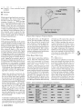
Third, a means of displaying the accumulation of time. Figure 1 shows a
simple clock block diagram, including
a method of presetting the arbitrary
starting time and obtaining an electrical time reading from the clock (timecode-generator).
Maintenance of accurate frequency
There are five basic types of time base
oscillators:
Accurate time transfer
w
w
Determination of radio propagation
path delays
w TCXO - Temperature compensated
w
Maximization of the frequency cali-
XO -Room temperature crystal oscillator (sometimesreferred to as RTXO)
crystal oscillator
Preset
Frequency
Source
I
Accumulator
I
Display
‘ I
1
I
Time Code Output
~~
Figure 1. Basic Clock
0 HewleH-Packard 1994
Pub. NO. 5952-3466
WWW.HPARCHIVE.COM
rn
OvenXO - Oven controlled crystal
oscillator
rn
Rubidium
Long Term Stability
or Aging
Cesium
Each type of time base has its own characteristics. The room temperature
model would be used in a portable
counter. Usually, the better the time
base, the longer it takes to verify it; the
poorer the time base, the harder it is to
adjust. Some time-base specifications
would be impractical to completely
vedy, so operator judgment is required
to identify which parameters have to
be checked, when to adjust the time
base, and when to predict final performance based upon rate of change of
measured performance.
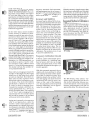
Time Base Aging
The physical properties of the quartz
crystal exhibit a gradual change with
time resulting in a gradual cumulative
frequency drift called “aging.” See Figure 2. The aging rate is dependent on
the inherent quality of the crystals
used, and goes on all the time. Aging
is often specified in terms of frequency
changes-per-month since temperature
and other effects would mask the small
amount of aging for a shorter time period. Aging for air crystals is given in
frequency changes-per-month as it is
not practical to accurately and correctly
measure over any shorter averaging
period. For a good RTXO, the aging rate
is typically of the order of 3 parts per
lo7per month. For a high quality ovencontrolled oscillator, the aging rate is
typically 1.5 parts per lo8per month.
Aging rate specifies maximum frequency change with time. Any oscillator can be much better than specified
but will never be worse than the indicated rate unless it is malfunctioning.
You may have noticed that HP has two
kinds of specifications-some oscillators are specified as having a daily aging rate, such as <3 x 10⁻⁹/day,while
others are specified as having a
monthly aging rate, such as <3 x lo-’/
month. HI’oscillators with a daily aging rate specification use ovens that
sufficiently buffer the oscillator from
the environment.
To determine crystal aging rate, one has
to check the oscillator once a day when
room temperature is at a constant value,
plot these points for approximately a
2
BENCH BRIEFS
Short Term Stability
Days From Calibration
Figure 2. Effect of Aging on Frequency Stability
month, then draw a line through the
points. The slope of the line is the aging
rate of the crystal. By doing this you
have created an “historical aging rate”
of your unit. This is an important concept and each instrument should have
its own history record. Table 1summarizes the oscillator characteristics described, utilizing typical specifications
of well-designed oscillators.
Time Base Warm Up
Under typical operating conditions,
that is, when the instrument’s power
cord is left connected to the power
source, there is no warm up because the
time base is kept ”warm” or in a
”standby” mode. However, if the unit
has been disconnected from the power
source for 24 hours or more, the instrument should technically be warmed up
for up to 30 days for it to meet guaranteed specifications. This may not be
practical. Our experience has shown
that approximately 85 percent of new
units and 95 percent of older units will
be within specificationsafter three days
Time Base Typical
Aging
Type
xo
TCXO
OvenXO
Rubidium
Cesium
Typical Shift
for 5 C ”
3 x 10’
5 x lo4
per month
1 x 10⁷
1XlOS
per month
5 x 10’O
5 x 10‘0
per day
1 x lo-’‘
5 x lo“*
per month
None
3 x 10’2
(Primary Std.)
WWW.HPARCHIVE.COM
of warm up. Of course, this is due to
the aging process slowing down over
time. A typical problem you may encounter with some of the older units is
that the time base has aged to a point
where the mechanical adjustment can
no longer compensate the frequency
drift because the mechanical adjusting
device has reached the physical limit
of its travel. On other older units, drift
may be almost non-existent.
The Question
Do you have to calibrate an oven time
base even though the manual for the
instrument being calibrated does not
have a performance test for it? The answer is YES. The oven time base needs
to have a drift test performed. The decision to remove offset depends upon
the needs of the customer and the type
of time base being calibrated. Calibration should always be checked after
repair, after being shipped (shock can
cause an offset of 1part in lo8, and you
don’t know in which direction), or periodically to ensure that measurements
Allowable
Offset
Typical
Warmup
Allan Variance
(T=l sec.)
60 Hz
30 minutes
1x
13 Hz
3 hours
1 x 10’0
150mHz
3 days
5 x 10-12
400 LHZ
4hours
7 x 10¹²
6kHz
45 minutes 1 x 10¹¹
(21.5 nseclhour)
lo9
2ND QUARTER 1994
made with these devices are within
specifications ACCORDING TO THE
USE OF THE INSTRUMENT.This is an
important concept. Many users expect
an oven time base to have a written
specification to tell them exactly when
the cumulative offset caused by aging
has crossed some specification bound.
These oscillators are just not specified
in this manner. The use of the time base
and the measurement needs of the user
dictate how the time base is to be calibrated and supported.
On the other hand, crystal oscillator
(clock) accuracy is seldom of consequence in practical time interval mcasurements. Most electronic counters
have a quartz oscillator with an accuracy of 1part in lo6(1part per million)
or better. As a result, the effect of oscillator stability does not affect a time interval measurement unless the display
has 5 or 6 valid digits of information.
While it is possible to measure long intervals with high resolution, most practical measurements today are the rise
time of fast signals, propagation time
through high-speed logic, or on narrow
pulses. Resolving a 5 Fsec interval to 1
nanosecond entails only 4 digits of information - i.e., 5000 nanoseconds - so
an oscillator as poor as 1part in a million introduces only 1/2OOth as much
error as t1count for this measurement.
For shorter intervals the oscillator error is proportionally less.
Time interval averaging increases the
number of valid digits, but here again
usually not to the extent that crystal
accuracy is important. Short-term stability may become important when
doing time-interval averaging on narrow pulses. The short-term stability
specification is statistical in nature so
is worse for short averaging times.
Consider for example a short-term accuracy specification of 1 x
for a 1
second averaging time. This would be
1x
for a 1 Fsec averaging time (5
nanoseconds for the example above)
and would be greater for an oscillator
with poorer short-term stability.
Aging rate is generally of consequence
only in an application where the
counter is used to make phase or time
measurements to compare high precision frequency standards. In this application a counter is used to measure the
time variations between once-per-second time ticks from the two different
frequency standards. Each time-interVal measurement may be as long as 1
second (1x lo6psec) on frequencies that
are stable 5 parts in 10l2or better, so a
stable crystal oscillator is needed.
What this means in simple terms is that
the time base is adjustable,and if its drift
rate is known, it can be set so that the
drift remains within specifications for a
longer period of time, therefore extending the interval between calibrations.
Accuracy and Stability
Accuracy may be defined as the closeness of a measurement to the true value
as fixed by a universally accepted standard. The measure of accuracy, however, is in terms of its complementary
notion, that is, deviation from true
value, or limit of error, so that high accuracy has a low deviation and low
accuracy a high deviation. The plots
shown in Figure 3 show successive
measurementsfor four cases. The readings in case 2 are more spread out. This
could be due to noise or the operator’s
inability to consistently read an analog
dial. The readings in case 3 are stable
but offset from actual value. The important thing is that this offset is a systematic error that can be removed by
calibration. The random errors of case
4 cannot be calibrated out.
Suggested Method of Calibration
There are two excellent HP products to
help an operator make these measurements quickly and accurately, and obtain a permanent record (or history)
when connected to a printer. They are
the HP 5372 Frequency and Time Interval Analyzer and the HI? 53310A
Modulation Domain Analyzer.
HP 5372A
Frequency Calibration Interval
In theory, a time system based upon a
quartz oscillator or a rubidium standard of known drift rate can be kept
within prescribed limits of error with
infrequent adjustments through a systematic approach.
With this systematic approach, the oscillator and clock are preset to offsets
that will keep the time system operating within a selected accuracy for a
long time despite the oscillator’s drift.
This drift (aging rate) must be known
(measured) and must be nearly constant, so that a plot of the frequency
over the adjustment interval (periods
between calibration) can be approximated by a straight line.
Case 1
ACCURATE
and
STABLE
Case 2
ACCURATE;
not
STABLE
HP 5331OA
The HI? 53310A, often called a “frequency scope” allows the user to visually see the relationship between successive data points, with no dead time
between measurements and with no
appreciable delay. This allows the user
Case 3
STABLE;
not
ACCURATE
Case 4
not ACCURATE
not STABLE
Figure 3.Accuracy
BENCH BRIEFS 3
2ND QUARTER 1994
WWW.HPARCHIVE.COM
to "zero-in" a measurement quickly
without the time-consuming and frustrating back-and-forth "clockwise-alitle;" "counter-clockwise-a-bit;"
"clockwise again," etc.
The HP 5372A allows you to measure
phase shift continuously over a period
of up to 18 hours and provides built-in
Allan variance calculations.
Each unit has marker readouts that allow the operator to express frequency
differences in the conventional "partsin-the-10-to-the-nth" notation with a
minimum probability of mathematical
or procedural error.
One thing cannot be over-stressed; the
limiting factor for almost all time bases
is your ability to keep the temperature
constant for the duration of the test.
This is why the ability to make measurements and adjustments quickly is
so important.
Once you have created a historical rate
of drift (aging) for your particular instrument, you can calibrate it to an offset to take advantage of the known
drift. For example, if you know that the
time base drifts from low to high at a
certain rate, you can calibrate your unit
at the low end of its specification so that
it will drift from low through center
and be at the high end of its specification at a prescribed point in time.
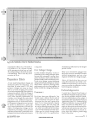
Recalibration Charts for
Quartz Oscillators and
Rubidium Standards
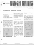
Figures 3a and 3b are useful for estimating the length in days of the
recalibration cycle for an oscillator with
a known drift rate, which will keep the
time system based on that oscillator
within prescribed error limits. A
recalibration cycle is the time, in days,
that can be allowed to pass between
calibrationadjustments.A shorter cycle
(more frequency adjustments) is
needed to keep a system accurate to
t l O O IJ.S (total time excursion equals
200 ks), rather than to 1ms.
To use the charts, select the slant line
marked for the aging, or drift rate -
parts-per-day for quartz oscillatorsand
parts-per-month for rubidium standards - of the oscillator. Note the intersection of this line with the horizontal line corresponding to the permitted
error excursion. This intersection, referred down to the horizontal axis,
gives the recalibration cycle.
Example 1.
A time system is to be maintained to
within 10ms based on a quartz oscillator with a positive aging rate at 5 x 10-lo/
day. Use Figure 3a to estimate the
length of the recalibration cycle by locating the slant line marked 5 x lO-*O/
day and note its intersection with the
horizontal line corresponding to a total time excursion of 20 ms (+lo ms).
The answer read from the chart is 60
days. Note that to use Figure 3a, aging
rate must be expressed in parts-per-day
and permitted time excusion in milliseconds.
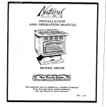
Example 2.
A rubidium-based time system is to be
Figure 3a. Recalibration Chart for Quartz Oscillators.
4 BENCH BRIEFS
WWW.HPARCHIVE.COM
2ND QUARTER 1994
Figure 3b. Recalibration Chart for Rubidium Standards.
maintained within 10 us. The drift rate
is a positive 1 x lO-"/month. Looking
at the appropriate slant line on Figure
3b correspondingto the drift rate yields
a recalibration time of 101 days for an
excusion of 20 ks.
Temperature Effects
A very small temperature change can
drastically affect the frequency of a
time base. In some cases, 1/2T temperature change can cause as much
drift as 2 weeks of aging. Two points
are worth remembering with respect to
temperature effects. First, the change of
frequency with temperature is usually
not a linear function; furthermore, all
crystals, even though the same kind,
may have very different frequencytemperature curves. Individual oscillator frequency-temperature curves must
be made to determine a particular
unit's actual performance. Second, the
effects of temperature change can be
reduced by providing a more constant
ambient temperature (controlled room
temperature) when better performance
2ND QUARTER 1994
is required.
maintaining calibration for the longest
period of time.
Line Voltage Change
Crystal oscillator frequency is also influenced by line voltage changes (often
because the instrument's power dissipation increases,which causes the temperature inside of the instrumentto rise).
Good circuit design, proper buffering,
and good mechanicaldesign can reduce
these effects. Operators needing better
performance can use a line regulator to
better control line voltage fluctuations.
Keep your instruments plugged into
the power source to maintain constant
internal temperatures, and use a line
regulator to buffer h e voltage changes.
Above all, think about how you are
using the instrument and what is reasonable to expect from it. Do not try to
use your counter to calibrate a cesiumbeam frequency standard.
Acknowledgements:
Summary
Each time base ages differently. You
should create a history file for each of
your instruments and plot its drift.
Determine how the unit is going to be
used. If your measurements require
extreme accuracy, the time base will
have to be calibrated more often. Either
way, when you calibrate the time base,
adjust it to the extreme end of its specification and let it drift through center
to the other end of its specification,
WWW.HPARCHIVE.COM
I would like to thank Chris Franks at
the Hewlett-Packard Santa Clara Division for his guidance with this article.
For more information on the subject, I
recommend the free Hewlett-Packard
Application Note 52-2, Timekeeping and
Frequency Calibration. Ask your local HP
office for HP P / N 5952-7874. Comments on this article are invited and we
will answer each and every one. If you
have recommendations for future articles about this subject, please send
them to the editor.
0
BENCH BRIEFS 5
IoDerative Sumort Service for Self-Maintainers
r
lardware Support for Test and Measurement Systems
n Callenderklewlett-Pachrd
.traduction
:wlett-Packard Test & Measurement
,operative Support service for selflintainers provides all the essential
pport elements you need to compleznt your internal hardware maintence capabilities.With this serviceyou
11have everything you need to fully
dress your unique requirements. You
e your trained maintenance organition for labor and rely on HP for
lining, replacement parts, diagnostic
pport tools, repair documentation,
.d remote backup support.
w
Improve the productivity of your
system engineers and managers
w
Maximize your organization’s ability to maintain HP T&M systems
On-site start-up visit
Semi-annual on-site reviews
w
Significantlyenhance the productivity of your internal service organization
Electronic access to service notes
(through HP SupportLine)
w
Accurately predict your annual
maintenance costs
for self-maintainers provides the following features for HI’ Test and Measurement systems designated by HP as
eligible for this service.
License to use hardware diagnostics
and updates*
Remote hardware troubleshooting
assistance
Parts replenishment (03W only, excluded for 03X)*
One customer-initiated on-site HP
visit to repair hardware failure on eligible HP Test and Measurement Systems
Direct access to technical assistance
(MeasurementSystems Knowledge
Center)
lis cooperative support service is
,ailablefor HP’s large test &measureent systems. Examples are the HP
000 Series Digital IC Test Systems,
P 3060 and 3070 Board Test Systems,
Id the HP 9470/9472 Power Mixed
gnal Test Systems to name a few.
ore will be added to this list in the
ture.
Benefits
eatures
P T&M Cooperative Support service
w
Increase the availability of your test
and measurement systems
*The optional parts replenishment is
available under the 03W option electron only.
For More Information
Ask your HP office for the following
documents.
Description
HP P/N
HP Cooperative
Support User’s Guide
5962-9778E
HP Cooperative
Support Data Sheet
5962-8520E
HP Cooperative
5952-9777E
Support Terms and Conditions
Shared Loaner Contract
.oaner
Vogram
i I] irninates
.engthy
)owntimes
‘eny Jeung/Hewlett-Packard
or U.S. Customers Only
ustomers in the U.S. can eliminate
owntime for calibration and reduce
owntime for repair from a week to a
ay! Hewlett-Packard now offers an
ffordable way to quickly obtain a
mner signal generator so that you can
eep operating when your present siga1 generator needs calibration or reair. If you cannot afford downtime for
our HP8648A/B/C Signal Generator,
onsider the following two options:
BENCH BRIEFS
You can purchase a three-year loaner
contract.Any time your HP 8648A/B/C
Signal Generator fails during the three
years, a loaner instrument will be express mailed to you within hours. You
keep the loaner until your instrument
is repaired and returned.
You can also use the loaner once during the three years while your signal
generator is being calibrated.Since calibrations are planned in advance, you
can arrange to have the loaner arrive
at your location before disconnecting
your generator for calibration. Downtime will be limited to the time it takes
you to connect the loaner in place of
the instrument requiring calibration.
This three-year contract is available for
$500.00 U.S. If at any time during the
three years you want additional calibrations, you can have a loaner delivered for $200.00. Your instrument must
be repaired and calibrated at the
WWW.HPARCHIVE.COM
Hewlett-Packard Golden Gate Customer Service Center in California.
Costs of repair and calibration are not
included in this contract price.
Per-incident Usage
Per-incident service can be purchased
at any time you require a loaner by contacting the HP Golden Gate Customer
Service Center administration group at
(415)694-2620. Once this contract is set
up, you can then order a loaner for
!$350.00per usage to take the place of your
(See “Loaner Program,” page 7)
2ND QUARTER 1994
r
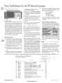
New Tes?Software for t h e RF Network Ana Ilyzer
fl
John VallelungalHewlett-Packard
Introdhction
'
Hewlett-Packard's Microwave Instruments Divhion has released a new version of test softwarefor the HP 8711A RF
Network Analyzer. This software is intended to replace the previous software
(HPP/N 08711-lOOO9).That version only
automated four of the eight required tests,
didnot allow equipment substitution,and
was difhcult to work with. The new version has eliminated these shortcomings
and has added several improvements,
some of whch are listed below.
Enhancements
rn
"7
rn
rn
The program includes graphical setup
COMeCtiOIlS,CUStOmiZed t0 YOW equipment being used. You will no longer
need to refer to the manual for proper
setup equipment and C O M W ~ ~ O ~ ~ .
Multiple equipment and mass storage
configurationscan be saved.
Data storage is automatic; results can
be archived and later retrieved at any
time.
Simple,jmmediak, one-disk operation.
Although installationto a hard drive is
preferred,it isnot required.This is NOT
an 'STE-9ooo' program.
rn Elimination of the "special" option of
the power sensor. The HP 8481D H70
is no longer required; a normal 8481D
will suffice.
rn Includes a quick HP-IB scan to venfy
equipment setups; DUT can be on a
different bus from test equipment.
rn Also includes several handy service
utilities.
rn Can be run on a PC using an HP BASIC Language Processor Card.
How to Obtain the Software
This program can be ordered as HP
part number 08711-10011 through your
local HP office. The price is approximately $50.00 U.S.
Thisnew versioncan now be used in place
of all the documented performance
tests in the manual which will save a considerable amount of test time.
Other Important HI?87llA News
HP recently released firmware revision
A.02.10 for the HP 8711A. This firmware
nowallowstheuseofastandardHP8481D
power sensor instead of the previously required HP 8481DOption H70. This sensor
is used in ALC adjustment #lo2 on those
instrumentswith abuilt-inattenuator (Op
tion 1El). Together with the abovetest software, the need for this special option sensor has been eliminated. However, care
must now be used when performing adjustment#lM.Followingthe procedm in
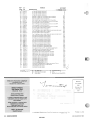
1994 Bench Briefs' Instrument
Service Note Index
SN
SN
Type No.
MR
IO
MA
IO
IO
IO
IO
IO
IO
MR
10
10
10
IO
IO
MR
MR
MR
MR
2ND QUARTER 1994
346C-02
3336AIBfC-17
3589A-01A
3779c-45
3779C-45A
3779D-49
3779D-49A
3785A-26
3787B-14
4145B-02A
4276A-07
4277A-11
4396A-01A
4935A-17A
5335A-17B
5342A-35C
5347A-09
5348~-n9
5508A-02A
Abstract
the manual could result in a non-function-
ing ALC. For further information, order
service note 8711A-05from:
Hewlett-Packard
Bench Briefs
100 MayfieldAve.
Mt. View, CA 94043
The new firmware is available as HP
P/N 08711-60063 through your local
HP office.
Service Manual Omissions
Severalcommonlyused part numbers for
75 ohm HP 8711As were inadvertently
omitted from the service manual. Please
add the following 75 ohm parts.
Descriotion
HP PIN
Front panel assembly
Front dress label
Test port assy
(conn and brackets)
52 to RF out cable
08711-60071
08711-80004
08711-60039
08711-20047
Also omitted was the entire chassis
(frameand interconnect board). The HP
P/N is 08711-60009 for all instrument
versions.
("Loaner Program," continued from page 6)
HP 8648A/B/C Signal Generator while
it is being repaired or calibratedat the HP
Golden Gate Customer Service Center.
For more information about either of
these programs, contact the HP Direct
Marketing Services group at 1-800835-4747,option 1.
0
HP FIRST (208)7111809
T Rr M Scction - Press 4
Password Section - P r c s 6
Password - 16683
FIP FIRST
Document ID No.
Mod eliminates 425MHz spurious oscillations
Instructions for replacing new A14 PC assembly
HP 3589A firmware revision histoly
Improved GvL measurementwhen high noise levels are present
Improved GvL measurementwhen high noise levels are present
Improved GvL measurement when high noise levels are present
Improved GvL measurementwhen high noise levels are present
Notification of part replacement
Preferred replacement for A3 CRT display module
SMII board rood prevents spike when measurng amps with a range change
Instructions on mplacing A4Q10 power transistor
lnstructions on replacing A4QlO power tramistor
Firmware update and A 1 CPU repair information
New volume control assembly for older instruments
Instructions on replacing front end Schmm amplifiers
Front panel replacement kit
New front membrane panel and new casting improve performance
New front membrane panel and new casting improve performance
EPROM firmware revision
WWW.HPARCHIVE.COM
I
6027
6048
5254
6014
6014
6015
6015
6016
61x5
6047
6009
6010
5642
5397
5597
6019
6045
6046
6006
BENCH BRIEFS 7
HP FIRST
Abstract
Document ID No.
c
AC input filter assembly replacement
AC input filter assembly replacement
AC input filter assembly replacement
AC input filter assembly replacement
Replacing 24v supply fuses with jumpers improves reliability
Replacing 24v supply fuses with jumpers improves reliability
Firmware upgrade kit improves performance
Mod A6 power supply to be compatible with A15 assemblies
New A15 RF assy elimins high displayed noise level in wide B/W
Firmware upgrade kit improves performance
New A15 RF assy elimins high displayed noise level in wide B/W
Firmware upgrade kit improves performance
New A15 RF assy elimins high displayed noise level in wide B/W
Firmware upgrade to address flatness instability
Firmware upgrade kit improves performance
New 5V reg improves power supply loading when mass mem mod connected
Firmware upgrade to address flatness instability
Finnware upgrade kit improves performance
New 5V reg improves power supply loading when mass meni mod connected
New PAL device eliminates instrument failures
New PAL device eliminates instrument failures
New PAL device eliminates instrument failures
New PAL device eliminates instrument failures
New PAL device eliminates instrument failures
New PAL device eliminates instrument failures
New PAL device eliminates instrument failures
New PAL device eliminates instrument failures
Alternative test procedure for TOH and POH ports
Alternative test procedure for TOH and POH ports
New capacitor corrects clock PLL lock problem at upper freqencies
Instructions to retrofitvirtual remote facility (Opt VO1)
Power supply modification improves reliability
Mod eliminates input resistance performance test failure
Mod eliminates input resistance performance test failure
Mod eliminates input resistance performance test failure
Mod eliminates input resistance performance test failure
Mod replaces defective BNC connector
Mod replaces defective BNC connector
Mod replaces defective BNC connector
Mod replaces defective BNC connector
Mod replaces defective BNC connector
Mod replaces defective BNC connector
Instructions on changing channel or trigger input connector to Type-N
New plastic tubing prevents power supply cable short
894 lON8943OA repair strategy
8941ON8943 1A repair strategy
IO
MR
PS
Information Only
Modification Recommended
Priority Safety
MA
SA
SM
c
Modification Available
Safety
Interoffice Service Memo (IOSM)
Bulk Rate
US. Postage
San Jose, CA
Permit No.
fAll
rights reserved Permission to reprint Bench Briefs granted upon written request to the Editor
Printed in U S A .
2ND QUARTER 1994
WWW.HPARCHIVE.COM