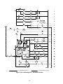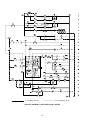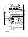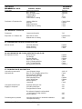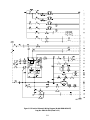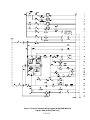
1
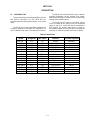
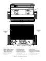
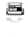
Bus Air
Conditioning
Unit
Rearmount
68RM40-504
68RM40-514
68RM40-524
T-250
OPERATION AND
SERVICE MANUAL
BUS AIR CONDITIONING UNIT
Rearmount
68RM40-504
68RM40-514
68RM40-524
Carrier Transicold Division, Carrier Corporation, P.O. Box 4805, Syracuse, N.Y. 13221
Carrier Corporation 1993 D Printed in U. S. A. 0493
TABLE OF CONTENTS
Section
Page
1
1.1
1.2
1.3
1.4
1.5
1.6
1.7
DESCRIPTION . . . . . . . . . . . . . . . . . . . . . . . . . . . . . . . . . . . . . . . . . . . . . . . . . . . . . . . . .
Introduction . . . . . . . . . . . . . . . . . . . . . . . . . . . . . . . . . . . . . . . . . . . . . . . . . . . . . . . . . . . .
Refrigeration System Component Specifications . . . . . . . . . . . . . . . . . . . . . . . . . . . . . .
Electrical Specifications . . . . . . . . . . . . . . . . . . . . . . . . . . . . . . . . . . . . . . . . . . . . . . . . . . .
Safety Devices . . . . . . . . . . . . . . . . . . . . . . . . . . . . . . . . . . . . . . . . . . . . . . . . . . . . . . . . . . .
System Operating Controls and Components . . . . . . . . . . . . . . . . . . . . . . . . . . . . . . . . .
Heater Flow Cycle . . . . . . . . . . . . . . . . . . . . . . . . . . . . . . . . . . . . . . . . . . . . . . . . . . . . . . .
Air Conditioning Refrigerant Cycle . . . . . . . . . . . . . . . . . . . . . . . . . . . . . . . . . . . . . . . . .
1-1
1-1
1-5
1-5
1-6
1-7
1-7
1-8
2
2.1
2.2
2.3
OPERATION . . . . . . . . . . . . . . . . . . . . . . . . . . . . . . . . . . . . . . . . . . . . . . . . . . . . . . . . . . .
Pre-trip Inspection . . . . . . . . . . . . . . . . . . . . . . . . . . . . . . . . . . . . . . . . . . . . . . . . . . . . . . .
Starting and Stopping Instructions . . . . . . . . . . . . . . . . . . . . . . . . . . . . . . . . . . . . . . . . . .
Control Circuit . . . . . . . . . . . . . . . . . . . . . . . . . . . . . . . . . . . . . . . . . . . . . . . . . . . . . . . . . .
2.3.1
Air Conditioning Circuit Operation . . . . . . . . . . . . . . . . . . . . . . . . . . . . . . . . . .
2.3.2
Ventilation Circuit Operation . . . . . . . . . . . . . . . . . . . . . . . . . . . . . . . . . . . . . . .
2.3.3
Heating Operation . . . . . . . . . . . . . . . . . . . . . . . . . . . . . . . . . . . . . . . . . . . . . . . .
2-1
2-1
2-1
2-1
2-1
2-2
2-2
3
3.1
3.2
3.3
3.4
TROUBLESHOOTING . . . . . . . . . . . . . . . . . . . . . . . . . . . . . . . . . . . . . . . . . . . . . . . . . . .
Unit Will Not Cool . . . . . . . . . . . . . . . . . . . . . . . . . . . . . . . . . . . . . . . . . . . . . . . . . . . . . . .
Unit Runs But has Insufficient Cooling . . . . . . . . . . . . . . . . . . . . . . . . . . . . . . . . . . . . . .
Abnormal Pressure . . . . . . . . . . . . . . . . . . . . . . . . . . . . . . . . . . . . . . . . . . . . . . . . . . . . . . .
Abnormal Noise and Vibrations . . . . . . . . . . . . . . . . . . . . . . . . . . . . . . . . . . . . . . . . . . . .
3.4.1
Abnormal Noise . . . . . . . . . . . . . . . . . . . . . . . . . . . . . . . . . . . . . . . . . . . . . . . . . .
3.4.2
Abnormal Vibration . . . . . . . . . . . . . . . . . . . . . . . . . . . . . . . . . . . . . . . . . . . . . . .
Temperature Controller Malfunction . . . . . . . . . . . . . . . . . . . . . . . . . . . . . . . . . . . . . . . .
No Evaporator Air Flow or Restricted Air Flow . . . . . . . . . . . . . . . . . . . . . . . . . . . . . .
Expansion Valve Malfunction . . . . . . . . . . . . . . . . . . . . . . . . . . . . . . . . . . . . . . . . . . . . . .
3-1
3-1
3-1
3-1
3-2
3-2
3-2
3-2
3-2
3-2
SERVICE . . . . . . . . . . . . . . . . . . . . . . . . . . . . . . . . . . . . . . . . . . . . . . . . . . . . . . . . . . . . . . .
Maintenance Schedule . . . . . . . . . . . . . . . . . . . . . . . . . . . . . . . . . . . . . . . . . . . . . . . . . . . .
Installing Manifold Gauges . . . . . . . . . . . . . . . . . . . . . . . . . . . . . . . . . . . . . . . . . . . . . . . .
Pumping The System Down or Removing The Refrigerant Charge . . . . . . . . . . . . . . .
4.3.1
System Pump Down . . . . . . . . . . . . . . . . . . . . . . . . . . . . . . . . . . . . . . . . . . . . . . .
4.3.2
Removing the Refrigerant Charge . . . . . . . . . . . . . . . . . . . . . . . . . . . . . . . . . . .
Refrigerant Leak Check . . . . . . . . . . . . . . . . . . . . . . . . . . . . . . . . . . . . . . . . . . . . . . . . . . .
Evacuation and Dehydration . . . . . . . . . . . . . . . . . . . . . . . . . . . . . . . . . . . . . . . . . . . . . .
Adding Refrigerant To System . . . . . . . . . . . . . . . . . . . . . . . . . . . . . . . . . . . . . . . . . . . . .
4.6.1
Adding Full Charge . . . . . . . . . . . . . . . . . . . . . . . . . . . . . . . . . . . . . . . . . . . . . . .
4.6.2
Adding Partial Charge . . . . . . . . . . . . . . . . . . . . . . . . . . . . . . . . . . . . . . . . . . . . .
Checking For Noncondensibles . . . . . . . . . . . . . . . . . . . . . . . . . . . . . . . . . . . . . . . . . . . . .
Checking and Replacing High or Low Pressure Cutout Switch . . . . . . . . . . . . . . . . . . .
4.8.1
Replacing High or Low Pressure Switch . . . . . . . . . . . . . . . . . . . . . . . . . . . . . .
4.8.2
Checking High or Low Pressure Switch . . . . . . . . . . . . . . . . . . . . . . . . . . . . . . .
Filter-drier . . . . . . . . . . . . . . . . . . . . . . . . . . . . . . . . . . . . . . . . . . . . . . . . . . . . . . . . . . . . . .
Thermostatic Expansion Valve . . . . . . . . . . . . . . . . . . . . . . . . . . . . . . . . . . . . . . . . . . . . .
05G Compressor Maintenance . . . . . . . . . . . . . . . . . . . . . . . . . . . . . . . . . . . . . . . . . . . . .
4.11.1 Removing the Compressor . . . . . . . . . . . . . . . . . . . . . . . . . . . . . . . . . . . . . . . . . .
4.11.2 Compressor Oil Level . . . . . . . . . . . . . . . . . . . . . . . . . . . . . . . . . . . . . . . . . . . . . .
Servicing Pressure Actuated Compressor Unloader (If Equipped) . . . . . . . . . . . . . . .
Electrical Compressor Unloader (If Equipped) . . . . . . . . . . . . . . . . . . . . . . . . . . . . . . .
4-1
4-1
4-1
4-2
4-2
4-2
4-2
4-2
4-3
4-3
4-3
4-4
4-4
4-4
4-4
4-4
4-5
4-5
4-5
4-6
4-7
4-8
3.5
3.6
3.7
4
4.1
4.2
4.3
4.4
4.5
4.6
4.7
4.8
4.9
4.10
4.11
4.12
4.13
i
TABLE OF CONTENTS (CONT’D)
Section
5
5.1
Page
ELECTRICAL SCHEMATIC WIRING DIAGRAM
Introduction . . . . . . . . . . . . . . . . . . . . . . . . . . . . . . . . . . . . . . . . . . . . . . . . . . . . . . . . . . . .
5-1
LIST OF ILLUSTRATIONS
Figure
1-1
1-2
1-3
1-4
1-5
Unit Assembly --- Back View . . . . . . . . . . . . . . . . . . . . . . . . . . . . . . . . . . . . . . . . . . . . .
Unit Assembly --- Inside View . . . . . . . . . . . . . . . . . . . . . . . . . . . . . . . . . . . . . . . . . . . .
Electrical Component Panel Assembly . . . . . . . . . . . . . . . . . . . . . . . . . . . . . . . . . . . . .
Heater Flow Cycle . . . . . . . . . . . . . . . . . . . . . . . . . . . . . . . . . . . . . . . . . . . . . . . . . . . . . .
Air Conditioning Cycle . . . . . . . . . . . . . . . . . . . . . . . . . . . . . . . . . . . . . . . . . . . . . . . . . .
Page
1-2
1-3
1-4
1-7
1-8
2-1
2-2
2-3
2-4
2-5
2-6
2-7
Unit Control Panel . . . . . . . . . . . . . . . . . . . . . . . . . . . . . . . . . . . . . . . . . . . . . . . . . . . . .
Temperature Controller Sequence --- Reheat . . . . . . . . . . . . . . . . . . . . . . . . . . . . . . . .
Temperature Controller Sequence --- Cycling Clutch . . . . . . . . . . . . . . . . . . . . . . . . .
Air Conditioning Mode --- with Reheat Controller . . . . . . . . . . . . . . . . . . . . . . . . . . .
Air Conditioning Mode --- with Clutch Cycling Controller . . . . . . . . . . . . . . . . . . . .
Vent Mode --- with Clutch Cycling Controller . . . . . . . . . . . . . . . . . . . . . . . . . . . . . . .
Heat Mode --- with Clutch Cycling Controller . . . . . . . . . . . . . . . . . . . . . . . . . . . . . . .
2-1
2-3
2-3
2-4
2-5
2-6
2-7
4-1
4-2
4-3
4-4
4-5
4-6
4-7
Manifold Gauge Set . . . . . . . . . . . . . . . . . . . . . . . . . . . . . . . . . . . . . . . . . . . . . . . . . . . .
Vacuum Pump Connections . . . . . . . . . . . . . . . . . . . . . . . . . . . . . . . . . . . . . . . . . . . . . .
Checking High Pressure Switch . . . . . . . . . . . . . . . . . . . . . . . . . . . . . . . . . . . . . . . . . . .
Thermostatic Expansion Valve . . . . . . . . . . . . . . . . . . . . . . . . . . . . . . . . . . . . . . . . . . . .
Removing Bypass Piston Plug . . . . . . . . . . . . . . . . . . . . . . . . . . . . . . . . . . . . . . . . . . . . .
O5G Compressor . . . . . . . . . . . . . . . . . . . . . . . . . . . . . . . . . . . . . . . . . . . . . . . . . . . . . . .
Electric Unloader Schematic . . . . . . . . . . . . . . . . . . . . . . . . . . . . . . . . . . . . . . . . . . . . .
4-1
4-3
4-4
4-5
4-6
4-6
4-8
5-1
5-2
5-3
5-4
5-5
5-6
5-7
Electrical Schematic Wiring Diagram (Models 68RM40-504 & 524) . . . . . . . . . . . .
Electrical Schematic Wiring Diagram (Model 68RM40-504-5) . . . . . . . . . . . . . . . . .
Electrical Schematic Wiring Diagram (Model 68RM40-504-3 & 504-7) . . . . . . . . . .
Electrical Schematic Wiring Diagram (Model 68RM40-504-13) . . . . . . . . . . . . . . . .
Electrical Schematic Wiring Diagram (Model 68RM40-504-27) . . . . . . . . . . . . . . . .
Electrical Schematic Wiring Diagram (Model 68RM40-504-23) . . . . . . . . . . . . . . . .
Electrical Schematic Wiring Diagram (Model 68RM40-524-11) . . . . . . . . . . . . . . . .
5-2
5-4
5-6
5-8
5-10
5-12
5-14
LIST OF TABLES
Table
Page
1-1
1-2
Model Chart . . . . . . . . . . . . . . . . . . . . . . . . . . . . . . . . . . . . . . . . . . . . . . . . . . . . . . . . . . .
Safety Devices . . . . . . . . . . . . . . . . . . . . . . . . . . . . . . . . . . . . . . . . . . . . . . . . . . . . . . . . .
1-1
1-6
4-1
4-2
R-22 Pressure---Temperature Chart . . . . . . . . . . . . . . . . . . . . . . . . . . . . . . . . . . . . . . .
R-134a Temperature---Pressure Chart . . . . . . . . . . . . . . . . . . . . . . . . . . . . . . . . . . . . . .
4-8
4-9
ii
SECTION 1
DESCRIPTION
1.1
The RM40 unit interfaces with the bus’s (customer
supplied) compressor, driver’s switches, floor heater,
water valves and pump to provide a full air conditioning,
heating and ventilation system.
INTRODUCTION
This manual contains Operating and Electrical Data,
and Service Instructions for the RM40 Bus Air
Conditioning and Heating systems shown in the model
below.
The RM40 has two types of controllers Cycling
Clutch or Reheat. With Cycling Clutch, the compressor
cycles on and off to control bus interior temperature.
With Reheat, the coolant valve opens or closes on
thermostat command to control bus interior temperature
while the air conditioning mode continues to operate.
The RM40 unit is a one-piece system consisting of a
condenser, evaporator, and heater coil assemblies. The
unit is installed in the rear A/C compartment of the bus.
Table 1-1. Model Chart
Model
Refrigerant
TMC Option
Controller
RM40-504
RM40-504-1
RM40-504-3
RM40-504-4
RM40-504-5
RM40-504-7
RM40-504-8
RM40-504-9
RM40-504-10
RM40-504-13
RM40-504-23
RM40-504-27
RM40-514
RM40-524
RM40-524-11
R-22
R-22
R-22
R-22
R-22
R-22
R-22
R-22
R-22
R-22
R-22
R-22
NONE
R-134a
R-134a
C71
C72
C74
C74-1
C73
C74
C71-1
C72-1
C74-1
C73
C71-1
C74
CTE
C71
C71
Reheat
Cycling Clutch
Cycling Clutch
Cycling Clutch
Reheat
Cycling Clutch
Reheat
Cycling Clutch
Cycling Clutch
Reheat
Reheat
Cycling Clutch
HEAT ONLY
Reheat
Reheat
1-1
Driver’s Switches
(customer supplied)
Automatic
Automatic
4 Mode
4 Mode
4 Mode
4 Mode
Automatic
Automatic
4 Mode
4 Mode
Automatic
4 Mode
--Automatic
Automatic
21
21
1
TOP VIEW
1
CURBSIDE
(CS)
ROADSIDE
(RS)
2
1.
2.
3.
4.
3
Condenser Coil
Evaporator Blower Shroud
Heater Coil (See Figure 1-4)
Wire Connection to Main
Water Valve Assembly
5. Evaporator Blower Motor
6. Receiver Outlet Valve
7. Filter-Drier
4
5
6
7 8 9 10 11 12 13 14 15
8.
9.
10.
11.
12.
13.
Receiver
Sight Glass
High Pressure Switch
Low Pressure Switch
Suction Line Service Port
Suction Line Connection
to Compressor
14. Thermostatic Expansion Valve
Figure 1-1. Unit Assembly --- Back View
1-2
16
15.
16.
17.
18.
19.
17 18
19 20
Condenser Fan Switch
Filter-Drier Outlet Valve
Access Panel
Discharge Line Service Port
Discharge Line Connection to
Compressor
20. Discharge Line Check Valve
21. Condenser Fan Motor
11
1
2
3
4
1.
2.
3.
4.
5.
6.
5
6
7
8
9
10
7.
8.
9.
10.
11.
Upper Mounting Bracket
240 Watt Resistor
440 Watt Resistor
Evaporator Blower Wheel
Lower Mounting Bracket
Electrical Panel (See Figure 1-3)
Controller
Harness Terminal Block
Evaporator Air Filter
Evaporator Coil
24 V Interface Plug
Figure 1-2. Unit Assembly --- Inside View
1-3
1
2
3
4
5
6
7
8
9
C
L
W
10
B1
#1
11
B2
12
13
20
F
H
#2
14
#3
15
#4
16
17
#5
18
19
1. Floor Heater Circuit Breaker (CB1) --- 8 Amp
2. Compressor Clutch and Water Pump
Circuit Breaker (CB2) --- 15 Amp
3. Evaporator Fan Motor No.1
Circuit Breaker (CB3) --- 35 Amp
4. Evaporator Fan Motor No. 2
Circuit Breaker (CB4) --- 35 Amp
5. Condenser Fan Motor No.1
Circuit Breaker (CB5) --- 50 Amp
6. Condenser Fan Motor No. 2
Circuit Breaker (CB6) --- 50 Amp
7. Evaporator Blower Speed Switch (EBS)
8. Cool Relay (C)
9. Lock-In Relay (L)
10.
11.
12.
13.
14.
15.
16.
17.
18.
19.
20.
Water Pump Relay (W)
Blower Relay No.1 (B1)
Blower Relay No.2 (B2)
Floor Blower Relay (F)
Motor Contactor #1 (MC1)
Low Speed
Diode No.4 (D4)
Motor Contactor #2 (MC2)
High Speed
Motor Contactor #3 (MC3)
Motor Contactor #4 (MC4)
Motor Contactor #5 (MC5)
Speed
Heat Relay (H)
Figure 1-3. Electrical Component Panel Assembly
1-4
--- Evaporator Blower
--- Evaporator Blower
--- Condenser Fan No.1
--- Condenser Fan No.2
--- Condenser Fan High
R-134a Units
1.2 REFRIGERATION SYSTEM COMPONENT
SPECIFICATIONS
a. Refrigeration Charge
R-22 or R-134a: 16 to 17 lb.
b. Compressor
Model: 05G
No. of Cylinder: 6
Weight (Dry): 145 lbs. (66 kg) including clutch
Oil Charge: 6.75 pints (3.2 liters)
Oil Level:
Old Crankcase (before S/N 4994J):
Bottom to 1/4 of sight glass
New Crankcase (beginning S/N 4994J):
Between Min---Max marks on crankcase
Approved Compressor Oils ---R-22
Calumet Refining Co.:R030
Texaco : WF68
Witco: 4GS Suniso
Approved Compressor Oils ---R-134a
Castrol: Icematic SW68C
Mobil: EAL Artic 68
ICI: Emkarate RL68H
c. 05G Compressor Pressure Unloaders (Optional)
Opens at: 300 10 psig (21 .7 kg/cm@)
Closes at: 200 10 psig (14 .7 kg/cm@)
h. Condenser Fan Switch (CFS)
R-22 Units
Closes for high speed: 32010 psig (22.5 .7
kg/cm@)
Opens for Low Speed: 250 10 psig (17.8 .7
kg/cm@)
R-134a Units
Closes for high speed: 220 10 psig (15.5 .7
kg/cm@)
Opens for Low Speed: 17010 psig (12 .7 kg/cm@)
i. Freeze Protection Temperature Switch (FPTS)
Opens at: 32 2_F (0_C)
Closes at: 38 2_F (3.3_C)
PRESSURE UNLOADER
First Unloader
Second Unloader
Refrigerant Load Up Unload Load Up Unload
R-22
65 psig 55 psig 60 psig 50 psig
R-134a
36 psig 30 psig 30 psig 24 psig
j. Water Temperature Switch (WTS)
(Customer Supplied)
k. Unit Weight
d. 05G Compressor Electric Unloaders
Pressure Switches UPS1 & UPS2 (Optional)
Approximate: 600 lb (272 kg)
UNLOADER PRESSURE SWITCH
UPS1
UPS2
Refrigerant Load Up Unload Load Up Unload
R-22
75 psig 60 psig 65 psig 50 psig
1.3 ELECTRICAL SPECIFICATIONS
a. Evaporator/Heater Blower Motor
e. Thermostatic Expansion Valve
R-22 Units
Superheat Setting: 12_F (6.7_C)
MOP Setting: 95.5 7 psig (6.7 kg/cm@)
R-134a Units
Superheat Setting: 10_F (5.6_C)
MOP Setting: 53.9 4 psig (3.8 kg/cm@)
f. Low Pressure Switch (LPS)
Opens at: 6 3 psig (.42 .2 kg/cm@)
Closes at: 25 3 psig (2.8 .2 kg/cm@)
g. High Pressure Switch (HPS)
Bearing Lubrication: Factory Lubricated (additional
grease not required)
Horsepower: 0.6 (.44 kw)
Full Load Amps (FLA): 22 amps
Operating Speed: 1200 rpm
Voltage: 24 vdc
Dropping Resistor (DR1): 240 watts
b. Condenser Fan Motor
Bearing Lubrication: Factory Lubricated (additional
grease not required)
Horsepower: 0.5 hp (.37 kw)
Full Load Amps (FLA): 18 amps
Operating Speed: 1550 rpm
Voltage: 24 vdc
Dropping Resistor (DR2): 440 watts
R-22 Units
Opens at: 425 10 psig (30 .7 kg/cm@)
Closes at: 300 10 psig (21 .7 kg/cm@)
1-5
During the reheat mode, operation will
automatically stop in the same manner as indicated in the
A/C, vent or heat modes.
1.4 SAFETY DEVICES
System components are protected from damage
caused by unsafe operating conditions with safety devices
(listed in table Table 1-2).
The evaporator, condenser and floor heater motors
are protected independently against high current draw
with circuit breakers (CB3, 4, 5 & 6). The evaporator and
condenser motors are also protected from high
temperature with thermal protection switches (IP---CM
and IP---EM). If one of the evaporator motor safety
devices opens to stop one or both of the motors, low
pressure may become present in the system which may
cause the low pressure switch (LPS) to open, shutting the
unit down. If a condenser motor safety device opens, high
pressure may be become present, which may open the
high pressure switch (HPS) to shut the unit down.
During A/C mode, operation will automatically stop
when such unsafe conditions occur, by de-energizing the
compressor clutch and condenser motor coils if the
Freeze Protection Temperature Switch (FPTS), High
Pressure Switch (HPS) or Low Pressure Switch (LPS)
opens. The A/C fail lights (ACFL1 & 2) will illuminate to
indicate an unsafe condition. The evaporator blower
motors will continue to run to circulate the air.
When a safety device opens and causes the unit
operation to stop, place the climate control switch to off
position before resolving the problem. The safety device
may need to be manually reset before restarting the unit.
During the vent or heat modes, operation will
automatically stop if the circuit breaker, CB senses
excessive current draw by the TC or one of the operating
components.
Table 1-2. Safety Devices
Unsafe Condition
Safety Device
Device Setting
1. Excessive current draw by the
floor heater blowers.
1. Circuit Breaker --- CB1
Manual Reset
1. Opens at 8 amps
2. Excessive current draw by the
water pump or clutch coil.
2. Circuit Breaker --- CB2
Manual Reset
2. Opens at 15 amps
3. Excessive current draw by
evaporator motor no.1.
3. Circuit Breaker --- CB3
Manual Reset
3. Opens at 35 amps
4. Excessive current draw by
evaporator motor no. 2.
4. Circuit Breaker --- CB4
Manual Reset
4. Opens at 35 amps
5. Excessive current draw by
condenser motor no.1.
5. Circuit Breaker --- CB5
Manual Reset
5. Opens at 50 amps
6. Excessive current draw by
condenser motor no. 2.
6. Circuit Breaker --- CB6
Manual Reset
6. Opens at 50 amps
7. High compressor
discharge pressure.
7. High Pressure Switch (HPS)
Manual Reset
7. Refer to Section 1.2
8. Loss of refrigerant charge
8. Low Pressure Switch (LPS)
Automatic Reset
8. Opens at 6 ¦ 3 psig
(1.9 ¦ .28 kg/cm@)
9. Excessive system pressure in
the high side of the system.
9. High pressure relief valve
Replace
9. Opens at 450 psig
(31.6 kg/cm@)
1-6
experiences excessive temperature, the corresponding
EMTH switch will open to de-energize the motor
contacts. This will stop both evaporator blower motor.
1.5
SYSTEM OPERATING CONTROLS AND
COMPONENTS
a. Temperature Controller (Thermostat)
There are two types of controllers Cycling Clutch or
Reheat. With Cycling Clutch, the compressor cycles on
and off to control bus interior temperature. With Reheat,
the coolant valve opens or closes on thermostat command
to control bus interior temperature while the air
conditioning mode continues to operate.
Freeze Protection Temperature Switch (FPTS)
The Freeze Protection Temperature Switch (FPTS)
is located on the relay panel. The sensor is located on
evaporator coil. The FPTS protects the coil from frost
build-up. The switch opens when coil temperature falls to
30 2_F to de-energize the Lock-in Relay (L).
De-energizing the Lock-in Relay will cause the
condenser fan motors to stop and drop-out the
compressor clutch to stop the refrigerant cycle. At this
time only the evaporator blower will continue to run until
the coil temperature rises to 38 2_F, at which time the
switch will close to continue operation.
b. Manual Switches
Evaporator Blower Speed Switch (EBS)
The manual Evaporator Blower Speed switch (EBS)
is located next to the circuit breakers on the electrical
component panel (see Figure 1-3). When the EBS switch
is closed, the Motor Contact #2 will energize to lock-in
the evaporator motors in high speed.
d. Pressure Switches
Condenser Fan Switch (CFS)
The Condenser Fan Switch (CFS) is located on the
inlet line to the receiver (next to the filter-drier). If the
condenser coil pressure reaches 320 10 psig, the CFS
will close to energizes Motor Contactor #5 coil. This will
lock the Condenser Motors (CM1 & 2) in high speed until
the condenser pressure drops to 250 10 psig, resuming
low speed operation.
Climate Control Switch (CCS) ---Supplied by OEM
The Climate Control Switch (CCS) activates the
operation or the unit. This switch is located on the
driver’s control panel. When the Climate Control Switch
is closed, 24 vdc is fed from the circuit breaker (CB)
through the CCS switch to feed power to terminal F of the
temperature controller.
Defrost Switch (DEF) ---Supplied by OEM
1.6
HEATER FLOW CYCLE
Heating is controlled by the thermostat which
controls the operation of the water solenoid valve
(WSV). When water solenoid valve is energized, the
valve will open to allow engine coolant to flow through
the heater coil.
The Defrost Switch (DEF) when activated will
manually place the unit in defrost. When the DEF switch
is closed, the Water Valve coil will energize and close a
normally open set of contacts to feed 24 vdc to activate
Water Pump (WP). This switch when closed during the
A/C or Vent mode will override the temperature
controller heat relay to activate the water pump.
c. Thermal Switches
1
Water Temperature Switch (WTS) ---Supplied by OEM
The Water Temperature Switch (WTS) is located on
the block of the vehicle engine and senses the vehicles
engine coolant temperature. The WTS is a normally
closed switch that opens on temperature rise at 120_F
(49_C). When the vehicle water temperature is below
120_F, the switch is closed, completing a circuit for the
Blower Relays (B1 & B2). Energizing the Blower Relays
will prevent the floor blowers and evaporator blowers
from activating to prevent the circulation of cooler air
throughout the bus during the initial start-up of the
vehicle and unit.
2
3
4
5
Condenser Motor Thermal Protectors (CMTH)
Each condenser motor is equipped with an internal
thermal protector switch. If excessive motor temperature
exist, the CMTH switch will open to de-energize the
corresponding motor contactor. This will stop the
effected condenser motor.
7
1.
2.
3.
4.
Evaporator Motor Thermal Protectors (EMTH)
Each evaporator blower motor is equipped with an
internal thermal protector switch. If either motor
6
Heater Coil
Air/Bleed Hose
Inlet Tube
Air/Bleed Valve
5. Outlet Tube
6. Outlet Hose
7. Inlet Hose
Figure 1-4. Heater Flow Cycle
1-7
1.7
AIR CONDITIONING REFRIGERANT
CYCLE
4
When air conditioning is selected, the unit operates
as a vapor compression system using R-22 or R-134a as a
refrigerant. The main components of the system are the
reciprocating compressors, air-cooled condenser coil,
thermostatic expansion valve, and evaporator coil.
The compressors raise the pressure and the
temperature of the refrigerant and forces it into the
condenser tubes. The condenser fan circulates
surrounding air (which is a temperature lower than the
refrigerant) over the outside of the condenser tubes.
Heat transfer is established from the refrigerant (inside
the tubes) to the condenser air (flowing over the tubes).
The condenser tubes have fins designed to improve the
transfer of heat from the refrigerant gas to the air. This
removal of heat causes the refrigerant to liquefy; thus
liquid refrigerant leaves the condenser and flows to the
receiver.
10
9
7
The receiver serves as a liquid refrigerant reservoir
so that a constant supply of liquid is available to the
evaporator as needed and as a storage space when
pumping down the system. The receiver is equipped with
a sight glass to observe the refrigerant for restricted flow
and correct charge level.
8
6
3
5
11
The refrigerant leaves the receiver and flows through
the manual receiver outlet valve and through a
filter-drier where an absorbent keeps the refrigerant
clean and dry.
1
The liquid then flows to a thermostatic expansion
valve which reduces pressure and temperature of the
liquid and meters the flow of liquid refrigerant to the
evaporator to obtain maximum use of the evaporator
heat transfer surface.
1.
2.
3.
4.
5.
6.
7.
8.
9.
10.
11.
The low pressure, low temperature liquid that flows
into the evaporator tubes is colder than the air that is
circulated over the evaporator tubes by the evaporator
blower. Heat transfer is established from the evaporator
air (flowing over the tubes) to the refrigerant (inside the
tubes). The evaporator tubes have aluminum fins to
increase heat transfer from the air to the refrigerant;
therefore the cooler air is circulated to the interior of the
bus.
The transfer of heat from the air to the low
temperature liquid refrigerant in the evaporator causes
the liquid to vaporize. This low temperature, low
pressure vapor passes through the suction line.
The low pressure refrigerant vapor is now drawn into
the compressor where the cycle repeats.
When ventilation only is selected only the evaporator
blowers function to circulate air throughout the bus. The
refrigerant cycle will remain off.
1-8
Compressor
Discharge Line
Discharge Line Check Valve
Condenser Coil
Receiver
Filter-Drier Inlet Service Valve
Filter-Drier
Filter-Drier Outlet Service Valve
Thermostatic Expansion Valve
Evaporator Coil
Suction Line
Figure 1-5. Air Conditioning Cycle
2
SECTION 2
OPERATION
2.3 Control Circuit
The unit control circuit is 24 vdc supplied by the bus.
2.1 PRE-TRIP INSPECTION
After starting unit allow system to stabilize (10 to 15
minutes) and proceed as follows:
2.3.1 Air Conditioning Circuit Operation
When the climate control switch is placed in the ON
position, 24 vdc power is supplied through the switch to
terminal “F” of the temperature controller. With the
return air above 74_F, the controller will energize the A/C
relay to close a set of normally open contacts. This will
send power to the A/C terminal “C” of the controller.
From C the following relays will energizes:
1. Listen for abnormal noises. (Refer to section 3.4)
2. Check compressor oil level.
3. Check refrigerant level.
a. Lock-in Relay (L)
Power will be supplied through the Low Temperature
Switch and the High and Low Pressure Switches to
energize the Lock-in Relay (L). Energizing the the L
relay will close a set of normally open L contacts to allow
power to energize the Cool Relay (C) and Condenser Fan
Motor Contactor Relay MC3 and MC4.
2.2 STARTING AND STOPPING INSTRUCTIONS
a.
Starting
1. Start the vehicle engine.
2. Place the climate control switch in the ON
position.
b. Cool Relay (C)
Energizing the Cool Relay (C) will close a set of
normally open C contacts to activate the compressor
clutch coil. This will start the refrigerant cycle.
b. Stopping
1. Place the climate control switch in the OFF
position.
c. Motor Contactor Relay --- MC3
Energizing the Motor Contactor Relay (MC3) will
close a set of normally open MC3 contacts to start the
Condenser Fan Motor CM1.
NOTE
Be sure air conditioning unit is turned off before
stopping the engine.
d. Motor Contactor Relay --- MC4
Energizing the Motor Contactor Relay (MC4) will
close a set of normally open MC4 contacts to start
Condenser Fan Motor CM1 (low speed).
e. Motor Contactor Relay --- MC5
When the Condenser Fan Switch closes the Motor
Contactor Relay (MC5) will energizes and close a set of
normally open MC5 contacats to put Condenser Fan
Motors CM1 & CM2 in high speed. (Refer to section 1.2
for CFS settings.)
AUTOMATIC DRIVER CLIMATE CONTROL SWITCH
f. Motor Contactor Relay --- MC2
Energizing the Motor Contactor Relay (MC2) will
close a set of normally open MC2 contacats to put
Evaporator Fan Motors EM1 & EM2 in high speed.
g. Motor Contactor Relay --- MC1
Motor Contactor Relay MC1 will be energized
through a normally closed set of Blower Relay Contacts
(B2). Evaporator Fan Motors EM1 & EM2. The
energized MC1 relay will close a set of normally open
MC1 contacts to start the Evaporator Fan Motors (EM1
& EM2) (low speed).
DRIVER SELECT CLIMATE CONTROL SWITCH
If high pressure occures in the system the High
Pressure Switch (HPS) will cut out to open the circuit to
Figure 2-1. Unit Control Panel
2-1
the compressor contact to stop the compressor and
refrigerant flow. When the compressor shuts down due to
a safety device opening, the evaporator blower motors
will continue to run untill the A/C switch is placed in the
OFF position
NOTE
If the unit shuts down due to high current, the
circuit must be manually reset by pushing the
main circuit breaker (CB).
TEMPERATURE CONTROLLER (TC)
WITH REHEAT
TC TERMINALS
OPERATING MODE
B
C
D
E
Air Conditioning
Vent
Reheat
Heat
TEMPERATURE CONTROLLER (TC)
WITH CYCLING CLUTCH
TC TERMINALS
OPERATING
MODE
B
C
D
E
Air Conditioning
Vent
Heat
H
NOTE: Terminal “F” is input and terminal “A” is ground for the TC.
Power supplied from TC to Terminal
NO Power from TC
With the Reheat controller, the water pump and
valve will cycle on and off during the reheat mode. With
the Cycling Clutch controller, the compressor clutch will
cycle on and off during the reheat mode.
2.3.2 Ventilation Circuit Operation
24 vdc flows through the main circuit breaker (CB) to
the Vent Switch.
When the Vent switch is placed in the VENT
position, 24 vdc power is fed from the switch to energizes
the Motor Contactors (MC1 & MC2). Energizing the
MC will close a set of normally open MC contacts to
allow power to start the Evaporator Blower Motors
(EM).
2.3.3 Heating Operation
24 vdc flows through the main circuit breaker (CB) to
the Heat Switch.
When the Heat switch is placed in the HEAT
position, 24 vdc power is fed from the switch to
temperature controller (TC).
2-2
AIR
CONDITIONING
High Speed Blowers
AIR
CONDITIONING
High Speed Blowers
74_¦ 2_F
REHEAT &
AIR CONDITIONING
High Speed Blowers
VENT ONLY
Low Speed Blowers
70_¦ 2_F
HEAT
Low Speed Blowers
HEAT
Low Speed Blowers
Temperature Rise
Temperature Fall
Figure 2-2. Temperature Controller Sequence --- REHEAT
AIR
CONDITIONING
High Speed Blowers
AIR
CONDITIONING
High Speed Blowers
74_¦ 2_F
VENT ONLY
Low Speed Blowers
VENT ONLY
Low Speed Blowers
70_¦ 2_F
HEAT
Low Speed Blowers
HEAT
Low Speed Blowers
Temperature Rise
Temperature Fall
Figure 2-3. Temperature Controller Sequence --- CYCLING CLUTCH
2-3
= Energized Circuit
= De-energized Circuit
Figure 2-4. Air Conditioning Mode --- with Reheat Controller
2-4
= Energized Circuit
= De-energized Circuit
Figure 2-5. Air Conditioning Mode --- with Clutch Cycling Controller
2-5
= Energized Circuit
= De-energized Circuit
Figure 2-6. Vent Mode --- with Clutch Cycling Controller
2-6
= Energized Circuit
= De-energized Circuit
Figure 2-7. Heat Mode --- with Clutch Cycling Controller
2-7
SECTION 3
TROUBLESHOOTING
INDICATION/
TROUBLE
POSSIBLE CAUSES
REFERENCE
SECTION
3.1 UNIT WILL NOT COOL
Compressor will not run
F5 Fuse defective
R5 Relay defective
V-Belt defective
Compressor malfunction
Clutch malfunction
Safety device open
Check/Replace
Check/Replace
Check
See Note
Check/Replace
1.4
3.2 UNIT RUNS BUT HAS INSUFFICIENT COOLING
Compressor
Compressor valves defective
V-belt loose
See Note
Check
Refrigeration system
Abnormal pressures
No or restricted evaporator air flow
Expansion valve malfunction
Restricted refrigerant flow
NO TAG
3.6
3.7
4.9
High discharge pressure
Refrigerant overcharge
Noncondensibles in system
Condenser fan motor rotation incorrect
Condenser coil dirty
R6 & R7 Relays defective
F6 & F7 Fuses defective
4.3
4.7
Check
Clean
Check
Check
Low discharge pressure
Compressor valves(s) worn or broken
Low refrigerant charge
See Note
4.4 & 4.6
High suction pressure
Compressor valves worn or broken
See Note
Low suction pressure
Suction service valve partially closed
Receiver outlet valve partially closed
Filter-drier partially plugged
Low refrigerant charge
Expansion valve malfunction
Restricted air flow
Open
Open
4.9
4.4 & 4.6
3.7
Check
Low evaporator air flow
Blower running in reverse
Dirty air filter
Icing of coil
Check
Clean
Clean
Suction and discharge pressures
tend to equalize when unit
is operating
Compressor valves defective
See Note
3.3 ABNORMAL PRESSURE
NOTE: Refer to 05G Compressor manual, Form T-199.
3-1
3.4 ABNORMAL NOISE AND VIBRATIONS
INDICATION/
3.4.1
ABNORMAL NOISE
TROUBLE
POSSIBLE CAUSES
Compressor
Loose mounting bolts
Worn bearings
Worn or broken valves
Liquid slugging
Insufficient oil
Clutch loose or rubbing
Condenser or Evaporator fan
REFERENCE
SECTION
See Note
See Note
See Note
3.7
4.11.2
Check
Loose or defective
Bearings
Blade Interference
Blade broken or missing
Check /Adjust
Replace
Check
Check
Compressor
Loose mounting bolts
3.4.1
Evaporator or Condenser fan
Bent shaft on motor
Blade broken or missing
Replace motor
Check
3.4.2 ABNORMAL VIBRATION
3.5 TEMPERATURE CONTROLLER MALFUNCTION
Will not control
Controller defective
Sensor defective
Defective wiring
Replace
Replace
Check
3.6 NO EVAPORATOR AIR FLOW OR RESTRICTED AIR FLOW
No evaporator air flow
Motor burnout
Fan damage
Brushes defective
Return air filter dirty
R1 & R3 Relays defective
F1 & F3 Fuses defective
Wiring polarity incorrect
Replace
Replace
Replace
Check
Check
Check
Section 5
3.7 EXPANSION VALVE MALFUNCTION
Low suction pressure with
high superheat
Low refrigerant charge
Wax, oil or dirt plugging valve orifice
Ice formation at valve seat
Superheat setting too high
Power assembly failure
Loss of bulb charge
Broken capillary
Loose bulb
4.4 & 4.6
Check
4.5
4.10
Replace
Replace
4.10
Check
Low superheat and liquid
slugging in compressor
Superheat setting too low
Ice holding valve open
Foreign material in valve
4.10
4.10
4.10
Pin and seat of expansion valve eroded
or held open by foreign material
Broken capillary
4.10
4.10
Improper bulb location or loose bulb installation
Low superheat setting
4.10
4.10
Fluctuating suction pressure
NOTE: Refer to 05G Compressor manual, Form T-199.
3-2
SECTION 4
SERVICE
WARNING
Beware of rotating fan blades and unannounced starting of fans.
4.1 MAINTENANCE SCHEDULE
UNIT
ON
REFERENCE
SECTION
OPERATION
OFF
a. Daily Maintenance
X
X
Pre-trip inspection --- after starting
Check tension and condition of V-belt(s)
2.1
None
b. Weekly Inspection and Maintenance
X
X
X
X
Perform daily inspection
Check condenser, evaporator coils and air filters
Check refrigerant hoses and compressor shaft seal for leaks
Feel filter-drier for excessive temperature drop across drier.
4.1.1
None
4.4
4.9
c. Monthly Inspection and Maintenance
X
X
X
X
X
X
Perform weekly inspection and maintenance
Clean evaporator drain pan and hose(s)
Check wire harness for chafing and loose terminals
Check fan motor bearings
Check compressor mounting bolts for tightness
Check fan motor brushes
4.1.2
None
Replace/Tighten
None
None
None
the system can be charged or evacuated. Oil can also be
added to the system.
4.2 INSTALLING MANIFOLD GAUGES
The manifold gauge set can be used to determine
system operation pressure, add charge, equalize or
evacuate the system.
Low Pressure
High Pressure
Gauge
Gauge
a. Installing the Manifold Gauge Set
1. Remove both service valve stems and service
port caps. Backseat (counter clockwise) both service
valves.
2. Connect the high side hose tightly to discharge
service valve port.
Hand Valve
(Open)
A
A. Connection to
Low Side of System
B. Connection to
High Side of System
C
B
3. Connect the low side hose loosely to suction
service valve port.
Hand Valve
(Frontseated)
4. Loosen charging (center) hose at dummy fitting
of manifold set.
C. Connection to Either:
Vacuum Pump
Refrigerant Cylinder
Oil Container
Purge Line
5. Frontseat (clockwise) both manifold gauge hand
valves.
6.
turns.
Crack open discharge service valve 1/4 to 1/2
7. Slowly open (counter clockwise) manifold
discharge hand valve approximately one turn.
Figure 4-1. Manifold Gauge Set
8.
The manifold gauge in Figure 4-1 shows hand valves,
gauges and refrigerant openings. When the low pressure
hand valve is frontseated (turned all the way in), the low
(evaporator) pressure can be checked. When the high
pressure hand valve is frontseated, high (condensing)
pressure can be checked. When both valves are open
(turning counter clockwise), high pressure vapor will flow
into the low side. When the low pressure valve is open,
Tighten charging hose on to dummy fitting.
9. Slowly open the manifold suction hand valve to
purge line.
10. Tighten suction hose at the suction service valve
port.
11. Frontseat (close) both manifold hand valves.
12. Crack open suction service valve 1/4 to 1/2 turns.
4-1
1. If system is without refrigerant, charge system
with refrigerant to build up pressure between 30 to 50
psig (2.1 to 3.5 kg/cm@).
NOTES
It must be emphasized that only the correct
refrigerant drum be connected to pressurize the
system. Any other gas or vapor will contaminate
the system which will require additional purging
and evacuation of the high side (discharge) of
the system.
2. Check for leaks. The recommended procedure
for finding leaks in a system is with a halide torch or
electronic leak detector. Testing joints with soapsuds is
satisfactory only for locating large leaks.
3. Remove refrigerant using a refrigerant recovery
system and repair any leaks.
4. Evacuate and dehydrate the system. (Refer to
section 4.5)
5. Charge the unit Refer to section 4.6.
4.3 PUMPING THE SYSTEM DOWN OR
REMOVING THE REFRIGERANT CHARGE
NOTE
To avoid damage to the earth’s ozone layer, use a
refrigerant recovery system whenever removing
refrigerant.
4.3.1 System Pump Down
To service or replace the filter-drier, expansion valve,
evaporator coil, or suction line; pump the refrigerant into
condenser coil and receiver as follows:
a.
Install manifold gauge set. (Refer to section 4.2)
b. Frontseat filter-drier inlet valve by turning
clockwise. Start unit and run A/C. Stop the unit when the
suction pressure reaches 1 psig (0.1 kg/cm@) to maintain a
slight positive pressure.
c. Frontseat (close) suction service valve to trap the
refrigerant in the low side of the system between the
compressor suction service valve and the filter-drier inlet
valve.
4.5 EVACUATION AND DEHYDRATION
a. General
Moisture is the deadly enemy of refrigerant systems.
The presence of moisture in a refrigeration system can
have many undesirable effects. The most common are
copper plating, acid sludge formation, “freezing-up” of
metering devices by free water, and formation of acids,
resulting in metal corrosion.
d. Service or replace the necessary component on
the low side of the system.
NOTES
1. Before opening up any part of the system, a
slight positive pressure should be indicated gauge.
2. When opening up the refrigerant system,
certain parts may frost. Allow the part to warm to
ambient temperature before dismantling. This
avoids internal condensation which puts
moisture in the system.
e.
b. Preparation
1. Evacuate and dehydrate only after pressure leak
test. (Refer to section 4.4)
2. Essential tools to properly evacuate and
dehydrate any system include a good vacuum pump
(minimum 5 cfm = 8 cu/m volume displacement, CTD
P/N 07-00176-01) and a good vacuum indicator such as a
thermocouple vacuum gauge (vacuum indicator,
available through Robinair Manufacturing, Montpelier,
Ohio, Part Number 14010.)
Leak check connections refer to section 4.4.
f. Evacuate and dehydrate the low side refer to
section 4.5.
4.3.2 Removing the Refrigerant Charge
Connect a refrigerant recovery system to the unit to
remove refrigerant charge. Refer to instruction provided
by the manufacture of the refrigerant recovery system.
NOTE
It is not recommended using a compound gauge
because of it’s inherent inaccuracy.
4.4 REFRIGERANT LEAK CHECK
3. Keep the ambient temperature above 60_F
(15.6_C) to speed evaporation of moisture. If ambient
temperature is lower than 60_F (15.6_C), ice may form
before moisture removal is complete. Heat lamps or
alternate sources of heat may be used to raise system
temperature.
A refrigerant leak check should always be performed
after the system has been opened to replace or repair a
component.
To check for leaks in the refrigeration system,
perform the following procedure.
4-2
c. Procedure for Evacuation and
Dehydrating System
1. Remove refrigerant using a refrigerant recovery
system.
2. The recommended method is connecting three
lines (3/8” OD copper tubing or larger) to manifold.
Attach one line to the filter-drier outlet valve,
compressor suction and discharge service valves. (See
Figure 4-2)
3. Connect lines to unit and manifold and make
sure vacuum gauge valve is closed and vacuum pump
valve is open.
4. Start vacuum pump. Slowly open valves halfway.
Then open vacuum gauge valve.
5. Evacuate unit until vacuum gauge indicates 1500
microns (29.86 inches = 75.8 cm) Hg vacuum. Close
gauge valve, vacuum pump valve, and stop vacuum pump.
6. Break the vacuum with clean dry refrigerant.
Use refrigerant that the unit calls for. Raise system
pressure to approximately 2 psig.
7. Remove refrigerant using a refrigerant recovery
system.
8. Start vacuum pump and open all valves.
Dehydrate unit to 500 microns (29.90 inches = 75.9 cm)
Hg vacuum.
9. Close off pump valve and stop pump. Wait five
minutes to see if vacuum holds.
10. With a vacuum still in the unit, the refrigerant
charge may be drawn into the system from a refrigerant
container on weight scales.
10
11
13
12
9
4.6 ADDING REFRIGERANT TO SYSTEM
8
7
3
2
4
5
4.6.1 Adding Full Charge
a. Evacuate and dehydrate system refer to section
4.5.
b. Place appropriate refrigerant cylinder on scales
and connect charging hose from container to filter-drier
inlet valve.
c. Note weight of refrigerant and container.
d. Open liquid valve on refrigerant container.
Midseat filter-drier inlet valve and allow refrigerant to
flow into the unit. Correct charge will be found in section
1.2.
e. When drum weight (scale) indicates that the
correct charge has been added, close liquid line valve on
drum and backseat the filter-drier inlet valve.
6
1
1.
2.
3.
4.
5.
6.
7.
8.
9.
10.
11.
12.
13.
Refrigerant Recovery Unit
Refrigerant Cylinder
Evacuation Manifold
Valve
Vacuum Pump
Vacuum Gauge
Compressor
Suction Valve
Discharge Valve
Condenser
Evaporator
Receiver
Filter-Drier Outlet Valve
4.6.2 Adding Partial Charge
a. Start the vehicle engine and allow unit to
stabilize.
b. Place appropriate refrigerant cylinder on scales
and connect charging hose from container vapor valve to
filter-drier inlet valve or compressor suction service
valve.
c. Open service valve and add charge until level
appears at center of lower receiver sight glass.
d. Backseat suction service valve. Close vapor valve
on refrigerant drum and note weight. Replace all valve
caps.
Figure 4-2. Vacuum Pump Connections
4-3
f. Close cylinder valve and release pressure
through the bleed-off valve. As pressure drops to cut-in
point, the switch contacts should close indicating no
resistance on the ommeter.
g. Replace switch if it does not function as outlined
above.
4.7 CHECKING FOR NONCONDENSIBLES
To check for noncondensibles, proceed as follows:
a. Stabilize system to equalize pressure between
the suction and discharge side of the system.
b. Check temperature at the condenser and
receiver.
c. Check pressure at the compressor discharge
service valve.
1
d. Check saturation pressure as it corresponds to
the condenser/receiver temperature using the
pressure/temperature Table 4-1 or Table 4-2.
2
5
3
6
4
e. If gauge reading is 3 psig or more than the
calculated P/T pressure in step d, noncondensibles are
present.
f. Remove refrigerant using a refrigerant recovery
system.
g. Evacuate and dehydrate the system. (Refer to
section 4.5)
h. Charge the unit Refer to section 4.6.
1. Cylinder Valve
and Gauge
2. Pressure Regulator
3. Nitrogen Cylinder
4. Pressure Gauge
(0 to 400 psig =
0 to 36 kg/cm@)
5. Bleed-Off Valve
6. 1/4 inch Connection
Figure 4-3. Checking High Pressure Switch
4.8 CHECKING AND REPLACING HIGH OR
LOW PRESSURE CUTOUT SWITCH
4.9 FILTER-DRIER
To Check Filter-Drier
4.8.1 Replacing High or Low Pressure Switch
If the sight glass on the receiver appears to be
flashing or excessive bubbles are constantly moving
through the sight glass, the unit may have a low
refrigerant charge, or the filter-drier could be partially
plugged.
Check for a restricted or plugged filter-drier by
feeling the liquid line inlet and outlet connections of the
filter-drier. If the outlet side feels cooler than the inlet
side, then the filter-drier should be changed.
a. The high and low pressure switches are equipped
with schrader valve to allow removal and installation
without pumping the unit down.
b. Disconnect wiring from defective switch. The
high and low pressure switches are shown in Figure 1-1.
c. Install new cutout switch after verifying switch
settings. (Refer to section 4.8.2)
To Replace Filter-Drier
a. Pump down the unit. (Refer to section 4.3)
4.8.2 Checking High or Low Pressure Switch
WARNING
b. Replace filter-drier, ensuring that the arrow on
the filter-drier points in the direction of the refrigerant
flow.
Do not use a nitrogen cylinder without a
pressure regulator. Do not use oxygen in or near
a refrigeration system or as an explosion may
occur.
c.
a. Remove switch from unit. All units are equipped
with schrader valves at the high pressure switch
connection.
b. Connect an ohmmeter across switch terminals. If
the switch is good the ohmmeter will indicate no
resistance indicating the contacts are closed.
c. Connect switch to a cylinder of dry nitrogen (see
Figure 4-3).
d. Set nitrogen pressure regulator higher than
cut-out point on switch being tested. (Refer to section
1.2)
e. Open cylinder valve. Slowly open the regulator
valve to increase the pressure until it reaches cut-out
point. The switch should open, which is indicated by an
infinite reading on an ohmmeter (no continuity).
4-4
Check refrigerant level.
7. Note the temperature of the suction gas at the
expansion valve bulb. Subtract the saturation
temperature determined in Step 6 from the average
temperature measured in Step 7. The difference is the
superheat of the suction gas.
4.10 THERMOSTATIC EXPANSION VALVE
The thermal expansion valve is an automatic device
which maintains constant superheat of the refrigerant gas
leaving the evaporator regardless of suction pressure.
The valve functions are: (a) automatic response of
refrigerant flow to match the evaporator load and (b)
prevention of liquid refrigerant entering the compressor.
Unless the valve is defective, it seldom requires any
maintenance.
c. Adjusting Superheat
1
6
a. Replacing the Expansion Valve
1.
7
Pump down the unit. (Refer to section 4.3)
2. Remove insulation (Presstite) from expansion
valve bulb and then remove bulb from suction line.
2
3. Loosen flare nut and disconnect equalizer line
from expansion valve.
3
4
8
5
9
8
4. Remove flange screws and lift off power
assembly. Then remove the cage assembly. Check for
foreign material in valve body.
10
11
5. The thermal bulb is located below the center of
the suction line (4 or 7 o’clock position). This area must
be clean to ensure positive bulb contact. Strap thermal
bulb to suction line and insulate both with “Presstite.”
1.
2.
3.
4.
5.
6.
6. Install new gaskets and insert cage assembly and
install power assembly.
7.
Fasten equalizer tube to expansion valve.
8. Evacuate by placing vacuum pump on suction
service valve.
Power Head
Cap Seal
Flare Seal
Retaining Nut
Adjusting Stem
Equalizer Connection
7.
8
9.
10.
11.
Bulb
Gasket
Cage Assembly
Body Flange
Capscrew
Figure 4-4. Thermostatic Expansion Valve
1. Remove hex cap from side of TXV power head.
This will expose the adjusting stem which has a screw slot.
9. Open filter-drier inlet valve and then check
refrigerant level. (Refer to section 4.6.2)
2. With a screwdriver, turn the adjusting stem
clockwise to increase superheat; turn counterclockwise to
reduce superheat. Approximately 2 turns of the adjusting
stem will change super heat 1_F. Make adjustment slowly
to give the valve a chance to equalize at new setting.
10. Check superheat.
b. To Measure Superheat
1. Remove Presstite from expansion valve bulb and
suction line.
3.
Replace cap and check operation of unit.
2. Loosen one TXV bulb clamp and make sure area
under clamp (above TXV bulb) is clean.
4.11 05G COMPRESSOR MAINTENANCE
3. Place temperature thermocouple on top of the
TXV bulb (parallel) and then secure loosened clamp
making sure both bulbs are firmly secured to suction line.
Replace Presstite around bulb.
If compressor is inoperative and unit still has
refrigerant pressure, frontseat suction and discharge
service valves to trap most of the refrigerant in the unit.
4.11.1 Removing the compressor
If compressor runs, pump down the unit. (Refer to
section 4.3)
4. Connect an accurate gauge to the 1/4” port on
the suction service valve.
5.
a. Slowly release compressor pressure.
Run unit until unit has stabilized.
b. Remove bolts from suction and discharge service
valve flanges.
NOTE
When conducting this test the suction pressure
must be at least 6 psig (.42 kg/cm@) below the
expansion valve maximum operating pressure
(MOP). Refer to section 1.2 for MOP.
c. Disconnect wiring to the high and low pressure
cutout switches if equipped and the clutch. Identify
wiring and switches if necessary.
d. Attach sling or other device to the compressor and
remove compressor from the bus.
6. From the temperature/pressure chart determine
the saturation temperature corresponding to the
evaporator outlet pressure. Add an estimated suction
line loss of 2 psig (.14 kg/cm@) to the figure.
e. Remove the three socket head cap screws from
both cylinder heads that have the unloader valve on 05G
compressor. Remove the unloader valve and bypass
4-5
piston assembly, keeping the same capscrews with the
assembly. The original unloader valve must be
transferred to the replacement compressor. The plug
arrangement removed from the replacement is installed
in the original compressor as a seal. If piston is stuck, it
may be extracted by threading socket head capscrew into
top of piston. A small teflon seat ring at bottom of piston
must be removed.
NOTES
1. The service replacement 05G compressor is
sold without shutoff valves (but with valve
pads). The optional unloaders are not supplied
as the cylinder heads are shipped with plugs.
Customer should retain the original unloader
valves for use on replacement compressor.
1
2
9
3
8
7
4
6
2. The piston plug that is removed from the
replacement compressor head must be
installed in the failed compressor if returning
for warranty.
5
1. High Pressure
Switch Connection
2. Low Pressure
Switch Connection
3. Suction Service
Valve
4. Oil Fill Plug
3. Do not interchange allen head cap screws
that mount the piston plug and unloader, they
are not interchangeable.
4. Check oil level in service replacement
compressor. Refer to section 1.2 and 4.11.2.
GASKET
10
5.
6.
7.
8.
9.
10.
Bottom Plate
Oil Drain Plug
Oil Sight Glass
Oil Pump
Pressure Unloader
Discharge Service
Valve
Figure 4-6. O5G Compressor
SPRING
4.11.2 Compressor Oil Level
a. Checking the Compressor Oil Level
COMPRESSOR
HEAD
1. Start the unit and allow the system to stabilize.
BYPASS
PISTON
PLUG
FLANGE
COVER
2. Check the oil sight glass on the compressor to
ensure that no foaming of the oil is present after 20
minutes of operation. If the oil is foaming excessively
after 20 minutes of operation, check the refrigerant
system for flood-back of liquid refrigerant. Correct this
situation before proceeding.
CAP SCREWS
(NOT INTERCHANGEABLE
WITH CONTROL VALVE
SCREWS)
3. Check the level of the oil in the front sight glass
with the compressor operating. the correct level should
be between 1/4 and 1/2 of the sight glass. If the level is
above 1/2, oil must be removed from the compressor. To
remove oil from the compressor, follow step d. If the level
is below 1/8, add oil to the compressor following step b.
Figure 4-5. Removing Bypass Piston Plug
f. Remove the high and low pressure switch assembly
and install on new compressor after checking switch
setting.
g. Install compressor in unit by reversing steps b.
through g. It is recommended using new locknuts when
replacing compressor. Install new gaskets on service
valves and tighten bolts uniformly.
b. Adding Oil with Compressor in System
Two methods for adding oil are the oil pump method
and closed system method.
h. Attach two lines (with hand valves near vacuum
pump) to the suction and discharge service valves.
(Dehydrate and evacuate compressor to 500 microns
(29.90” Hg vacuum = 75.9 cm Hg vacuum). Turn off
valves on both lines to pump.
1. Oil Pump Method
One compressor oil pump that may be purchased is a
Robinair part no. 14388. This oil pump adapts to a one
U.S. gallon (3.785 liters) metal refrigeration oil container
and pumps 2-1/2 ounces (0.0725 liters) per stroke when
connected to the suction service valve port. Also there is
no need to remove pump from can after each use.
i. Fully backseat (open) both suction and discharge
service valves.
j. Remove vacuum pump lines and install manifold
gauges.
When the compressor is in operation, the pump check
valve prevents the loss of refrigerant, while allowing
servicemen to develop sufficient pressure to overcome
the operating suction pressure to add oil as necessary.
k. Start unit and check refrigerant level.
l. Check compressor oil level. (Refer to section
4.11.2) Add oil if necessary.
Backseat suction service valve and connect oil
charging hose to port. Crack the service valve and purge
the oil hose at oil pump. Add oil as necessary.
m. Check compressor unloader operation.
4-6
b. Turn large (1-1/6 in.) load-up set point
adjustment hex nut on top of unloader CW to bottom
stop. On models equipped with unloader adjustment jam
nut (1-1/2 in.), turn this nut CW to bottom stop, then turn
the load-up adjustment hex nut CW down against the jam
nut.
2. Closed System Method
In an emergency where an oil pump is not available,
oil may be drawn into the compressor through the suction
service valve.
CAUTION
Extreme care must be taken to ensure the
manifold
common
connection
remains
immersed in oil at all times. Otherwise air and
moisture will be drawn into the compressor.
c. Remove sealing caps (unscrew CCW) that cover
the pressure differential adjustment screws on side of
both unloader flanges.
d. Turn unloader differential screw CW to bottom
stop.
Connect the suction connection of the gauge
manifold to the compressor suction service valve port,
and immerse the common connection of the gauge
manifold in an open container of refrigeration oil. Crack
the suction service valve and gauge valve to vent a small
amount of refrigerant through the common connection
and the oil to purge the lines of air. Close the gauge
manifold valve.
e. Check oil level in compressor sight glass and
then start engine.
f.
g. Slowly turn the suction service valve stem CW
until the suction pressure is at the valves (cut-in) loaded
setting.
With the unit running, frontseat the suction service
valve and pull a vacuum in the compressor crankcase.
SLOWLY crack the suction gauge manifold valve and oil
will flow through the suction service valve into the
compressor. Add oil as necessary.
NOTE
At this point the difference between the
discharge and suction pressures also must be at
least 10 to 120 psig (7.0 to 8.4 kg/cm@). It may be
necessary to artificially load the system (i.e.,
block off condenser coil air flow or open hot
water valve) to attain the required system
pressures.
c. Adding Oil to Service Replacement Compressor
NOTE
For correct oil charge refer to section 1.2.
Service replacement compressors may or may
not be shipped with oil.
If compressor is without oil:
h. Turn the load-up adjustment nut on the pressure
unloader slowly CCW while observing system pressures,
until the pressures “jump” (i.e., rapid decrease in suction
pressure and increase in discharge pressure). The
cylinder head is now loaded. Leave the adjustment nut in
this position.
Add oil, through the suction service valve flange cavity
or by removing the oil fill plug (see Figure 4-6).
d. To Remove Oil from the Compressor:
1. If the oil level recorded in step a.3 above is at 3/4 of
the sight glass, remove 1-1/2 pints of oil from the
compressor. If at a full sight glass, remove 2-3/4 pints of
oil from the compressor.
i. Readjust the suction service valve until the
suction pressure is at the valve (cut out) unloaded setting.
j. Turn the pressure differential adjustment screw
slowly CCW until the pressures “jump” (i.e., rapid
increase in suction pressure and decrease in discharge
pressure). The cylinder head is now unloaded. Leave the
adjustment nut in this position.
2. Close suction service valve (frontseat) and pump
unit down to 3 to 5 psig . Frontseat discharge service valve
and slowly bleed remaining refrigerant.
3. Remove the oil drain plug on the bottom plate of
the compressor and drain the proper amount of oil from
the compressor. Replace the plug securely back into the
compressor.
k. This unloader is now completely set. Check for
repeatability by adjusting the suction service valve as
necessary.
4. Repeat step 1 to ensure proper oil level.
4.12
Run engine at fast idle for ten minutes.
l. Reinstall the sealing caps that cover the
differential adjustment screws, and tighten.
SERVICING PRESSURE ACTUATED
COMPRESSOR UNLOADER (If Equipped)
The unloader valve settings unloads (cuts out) and
loads (cuts in) are in section 1.2.
NOTE
On models equipped with unloader adjustment
jam nuts, turn these nuts CCW up tightly against
the load-up adjustment hex nut, to “lock-in”
unloader valve adjustment.
Start the following procedure with the compressor
not running.
a. Connect a set of manifold pressure gauges to the
service valves or high and low pressure switch
connections in order to monitor both discharge and
suction pressures.
m. Backseat both suction and discharge service
valves (turn CCW) and disconnect manifold gauge set.
4-7
4.13
The pressure switches (UPS1 & UPS2) settings are in
section 1.2.
ELECTRIC COMPRESSOR UNLOADER
(If Equipped)
The electric unloaders internal operation is similar
to that of the pressure activated unloaders except that
instead of being activated by the suction pressure, the
electric unloaders are activated by an electromagnetic
coil which is energized by a pressure switch monitoring
suction pressure. (See Figure 4-7)
24V
UL1
UPS1
UL2
Two pressure switches (mounted on the compressor,
each switch operating one unloader), control voltage to
the unloader coil. When suction pressure gets to the set
point of the pressure switch, it energizes the unloader coil
which activates unloading in the compressor head.
UPS2
Figure 4-7. Electric Unloader Schematic
Table 4-1. R-22 Pressure --- Temperature Chart
TEMPERATURE
_F
_C
---40
---36
---32
---28
---26
---24
---22
---20
---18
---16
---14
---12
---10
--- 8
--- 6
--- 4
--- 2
0
2
4
6
8
10
12
14
16
18
20
22
24
26
28
30
32
---40
---38
---36
---33
---32
---31
---30
---29
---28
---27
---26
---24
---23
---22
---21
---20
---19
---18
---17
---16
---14
---13
---12
---11
---10
--- 9
--- 8
--- 7
--- 6
--- 4
--- 3
--- 2
--- 1
0
Psig
.6
2.3
4.1
6.0
7.0
8.1
9.2
10.3
11.5
12.7
14.0
15.2
16.6
18.0
19.4
21.0
22.5
24.1
25.7
27.4
29.2
31.0
32.9
34.9
36.9
39.0
41.1
43.3
45.5
47.9
50.2
52.7
55.2
57.8
PRESSURE
Kg/cm@
Bar
.04
.16
.29
.42
.49
.57
.65
.72
.81
.89
.98
1.07
1.17
1.27
1.36
1.48
1.58
1.69
1.81
1.93
2.05
2.18
2.31
2.45
2.59
2.74
2.89
3.04
3.2
3.37
3.53
3.71
3.88
4.06
TEMPERATURE
_F
_C
.04
.16
.28
.41
.48
.56
.63
.71
.79
.88
.97
1.05
1.14
1.24
1.34
1.45
1.55
1.66
1.77
1.89
2.01
2.14
2.27
2.41
2.54
2.69
2.83
2.99
3.14
3.3
3.46
3.63
3.81
3.99
34
36
38
40
44
48
52
54
60
64
68
72
76
80
84
88
92
96
100
104
108
112
116
120
124
128
132
136
140
144
148
152
156
160
4-8
1
2
3
4
7
9
11
12
16
18
20
22
24
27
29
31
33
36
38
40
42
44
47
49
51
53
56
58
60
62
64
67
69
71
Psig
60.5
63.3
66.1
69
75.0
81.4
88.1
91.5
102.5
110.2
118.3
126.8
135.7
145
154.7
164.9
175.4
186.5
197.9
209.9
222.3
235.2
248.7
262.6
277.0
291.8
307.1
323.6
341.3
359.4
377.9
396.6
415.6
434.6
PRESSURE
Kg/cm@
Bar
4.25
4.45
4.65
4.85
5.27
5.72
6.19
6.43
7.21
7.75
8.32
8.91
9.54
10.19
10.88
11.59
12.33
13.11
13.91
14.76
15.63
16.54
17.49
18.46
19.48
20.52
21.59
22.75
24.0
25.27
26.57
27.88
29.22
30.56
4.17
4.36
4.56
4.76
5.17
5.61
6.07
6.31
7.07
7.6
8.16
8.74
9.36
10.0
10.67
11.37
12.09
12.86
13.64
14.47
15.33
16.22
17.15
18.11
19.10
20.12
21.17
22.31
23.53
24.78
26.06
27.34
28.65
29.96
Table 4-2. R-134a Temperature--- Pressure Chart
BOLD NO. = Inches Mercury Vacuum (cm Hg Vac)
PRESSURE
Temperature
_F
_C
PSIG Kg/cm2
Bar
---40
---35
---30
---25
---20
---18
---16
---14
---12
---10
--- 8
--- 6
--- 4
--- 2
0
2
4
6
8
10
12
14
16
18
20
22
24
26
28
30
32
34
36
38
40
45
50
55
60
65
70
75
80
85
90
95
100
105
110
115
120
125
130
135
140
145
150
155
---40
---37
---34
---32
---29
---28
---27
---26
---24
---23
---22
---21
---20
---19
---18
---17
---16
---14
---13
---12
---11
---10
--- 9
--- 8
--- 7
--- 6
--- 4
--- 3
--- 2
--- 1
0
1
2
3
4
7
10
13
16
18
21
24
27
29
32
35
38
41
43
46
49
52
54
57
60
63
66
68
14.6
12.3
9.7
6.7
3.5
2.1
0.6
0.4
1.2
2.0
2.9
3.7
4.6
5.6
6.5
7.6
8.6
9.7
10.8
12.0
13.2
14.5
15.8
17.1
18.5
19.9
21.4
22.9
24.5
26.1
27.8
29.6
31.3
33.2
35.1
40.1
45.5
51.2
57.4
64.1
71.1
78.7
86.7
95.3
104.3
114.0
124.2
135.0
146.4
158.4
171.2
184.6
198.7
213.6
229.2
245.6
262.9
281.1
0.49
0.42
0.33
0.23
0.12
0.07
0.02
0.03
0.08
0.14
0.20
0.26
0.32
0.39
0.45
0.52
0.59
0.67
0.74
0.83
0.91
1.00
1.09
1.18
1.28
1.37
1.48
1.58
1.69
1.80
1.92
2.04
2.16
2.29
2.42
2.76
3.14
3.53
3.96
4.42
4.90
5.43
5.98
6.57
7.19
7.86
8.56
9.31
10.09
10.92
11.80
12.73
13.70
14.73
15.80
16.93
18.13
19.37
4-9
37.08
31.25
24.64
17.00
8.89
5.33
1.52
0.03
0.08
0.14
0.20
0.26
0.32
0.39
0.46
0.53
0.60
0.68
0.76
0.84
0.93
1.02
1.11
1.20
1.30
1.40
1.50
1.61
1.72
1.84
1.95
2.08
2.20
2.33
2.47
2.82
3.20
3.60
4.04
4.51
5.00
5.53
6.10
6.70
7.33
8.01
8.73
9.49
10.29
11.14
12.04
12.98
13.97
15.02
16.11
17.27
18.48
19.76
SECTION 5
ELECTRICAL SCHEMATIC WIRING DIAGRAM
5.1 INTRODUCTION
This section contains Electrical Schematic Wiring Diagram covering the Models listed in Table 1-1. The following
general safety notices supplement the specific warnings and cautions appearing elsewhere in this manual. They are
recommended precautions that must be understood and applied during operation and maintenance of the equipment
covered herein.
WARNING
Beware of rotating fan blades and unannounced starting of fans.
WARNING
Do not use a nitrogen cylinder without a pressure regulator. Do not use oxygen in or near a refrigeration system
or as an explosion may occur.
5-1
Figure 5-1. Electrical Schematic Wiring Diagram (Models 68RM40-504 & 524)
Dwg. No. 68RM40-314 Rev B (Sheet 1 of 2)
5-2
Figure 5-1. Electrical Schematic Wiring Diagram (Models 68RM40-504 & 524)
Dwg. No. 68RM40-314 RevB (Sheet 2 of 2)
5-3
Figure 5-2. Electrical Schematic Wiring Diagram (Model 68RM40-504-5)
Dwg. No. 68RM40-1054 (Sheet 1 of 2)
5-4
Figure 5-2. Electrical Schematic Wiring Diagram (Model 68RM40-504-5)
Dwg. No. 68RM40-1054 (Sheet 2 of 2)
5-5
Figure 5-3. Electrical Schematic Wiring Diagram (Model 68RM40-504-3 & 504-7)
Dwg. No. 68RM40-1064 (Sheet 1 of 2)
5-6
Figure 5-3. Electrical Schematic Wiring Diagram (Models 68RM40-504-3 & 504-7)
Dwg. No. 68RM40-1064 (Sheet 2 of 2)
5-7
Figure 5-4. Electrical Schematic Wiring Diagram (Model 68RM40-504-13)
Dwg. No. 68RM40-1094 (Sheet 1 of 2)
5-8
Figure 5-4. Electrical Schematic Wiring Diagram (Model 68RM40-504-13)
Dwg. No. 68RM40-1094 (Sheet 2 of 2)
5-9
Figure 5-5. Electrical Schematic Wiring Diagram (Model 68RM40-504-27)
Dwg. No. 68RM40-1134 (Sheet 1 of 2)
5-10
Figure 5-5. Electrical Schematic Wiring Diagram (Model 68RM40-504-27)
Dwg. No. 68RM40-1134 (Sheet 2 of 2)
5-11
Figure 5-6. Electrical Schematic Wiring Diagram (Model 68RM40-504-23)
Dwg. No. 68RM40-1154 (Sheet 1 of 2)
5-12
Figure 5-6. Electrical Schematic Wiring Diagram (Model 68RM40-504-23)
Dwg. No. 68RM40-1154 (Sheet 2 of 2)
5-13
Figure 5-7. Electrical Schematic Wiring Diagram (Model 68RM40-524-11)
Dwg. No. 68RM40-1114 (Sheet 1 of 2)
5-14
Figure 5-7. Electrical Schematic Wiring Diagram (Model 68RM40-524-11)
Dwg. No. 68RM40-1114 (Sheet 2 of 2)
5-15/ 5-16