1
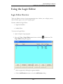
USER GUIDE
PLC WorkShop for Modicon
Version 5.76
© 2013 FasTrak SoftWorks, Inc.
www.fast-soft.com
262.238.8088
Throughout this document, PLC WorkShop for Modicon – 32 Bit will be referred
to as PLC WorkShop. PLC WorkShop is a trademark of FasTrak SoftWorks, Inc.
Modicon is a trademark of Schneider Electric, Inc. Windows is a registered
trademark of Microsoft Corporation.
LICENSE TERMS AND CONDITIONS
FasTrak SoftWorks, Inc.
Licensor is the owner of all rights, including the copyright, in and to that certain set of executable computer programs identified
in the Registration Form, including design and structure thereof (the "Software"), together with all manuals and other written or
printed technical material provided with the Software to explain its operation and to aid in its use (the "Documentation").
Licensee wishes to have the right to use the Software, and Licensor is willing to grant such a right to Licensee on the terms and
conditions set forth herein.
1. GRANT OF LICENSE. In consideration of Licensee's payment of the license fee referred to below and Licensee's agreement
to abide by the terms and conditions stated herein, FasTrak SoftWorks, Inc. (referred to as "Licensor") grants Licensee a
nonexclusive right to use and display one (1) copy of the Software with respect to one microcomputer at a time for so long as
Licensee complies with the terms hereof. Licensor retains the right to terminate this Agreement and Licensee's rights at any time,
by written notice to Licensee, in the event Licensee violates any of the provisions hereof.
Licensor reserves all rights in and to the Software and Documentation not expressly granted to Licensee herein. Licensee agrees
to pay Licensor the license fee specified by Licensor as of the date hereof, payable in full upon deliver of a copy of the
Software and Documentation to Licensee. Licensee acknowledges that the license fee payable hereunder is consideration solely
for the right to use the Software, and payment thereof will not entitle Licensee to support, assistance, training, maintenance or
other services, or the enhancements or modifications to the Software which may subsequently be developed by Licensor, except
as otherwise expressly provided in this Agreement.
2. LICENSEE'S AGREEMENTS. Licensee agrees to comply with the terms and conditions set forth in this Agreement,
specifically including but not limited to the following:
a. Licensee will take all reasonable steps to protect the Software from theft or use contrary to the terms of this
Agreement.
b. Licensee agrees to pay Licensor additional license fees as specified by Licensor if and to the extent Licensee intends
to use or does use the Software in any way beyond the scope of this Agreement.
c. Licensee agrees not to modify the Software and not to disassemble, decompile, or otherwise reverse engineer of the
Software.
d. Licensee agrees to either destroy or return the original and all existing copies of the Software to Licensor within
five (5) days after receiving notice of Licensor's termination of this Agreement.
e. Licensee agrees not to disclose the Software or Documentation or any part thereof or any information relating
thereto to any other party, it being understood that the same contains and/or represents confidential information
which is proprietary to Licensor.
3. OWNERSHIP OF SOFTWARE. Licensee shall be deemed to own only the magnetic or other physical media on which the
copy of the Software provided to Licensee is originally or subsequently recorded or fixed, as well as any boards, key-locks, or
cables provided for use with the Software, but an express condition of this Agreement is that Licensor shall at all times retain
ownership of the Software recorded on the original diskette copy and all subsequent copies of the Software, regardless of the
form or media in or on which the original or other copies may initially or subsequently exist. This Agreement does not
constitute a sale of any copy of the Software to Licensee.
4. POSSESSION AND COPYING. Licensee agrees that the Software will only be displayed or read into or used on one (1)
computer at a time, at the location designated for notices to Licensee under paragraph 13, below. Licensee may change the
computer on which Licensee uses the Software to another computer at such location. Licensee agrees not to make copies of the
Software other than for its own use, all of which copies shall be kept in the possession or direct control of Licensee. Licensee
agrees to place a label on the outside of all copies showing the program name, version number, if applicable, and Licensor's
copyright and trademark notices in the same form as they appear on the original licensed copy
5. TRANSFER OR REPRODUCTION. Licensee is not licensed to copy, rent, lease, transfer, network, reproduce, display or
otherwise distribute the Software except as specifically provided in this Agreement. Licensee understands that unauthorized
reproduction of copies of the Software and/or unauthorized transfer of any copy of the Software is a violation of law and will
subject Licensee to suit for damages, injunctive relief and attorney's fees. Licensee further understands that it is responsible for
the acts of its agents and employees. Licensee may not transfer any copy of the Software to another person or entity, on either a
permanent or temporary basis, unless Licensee obtains the prior written approval of Licensor which will ordinarily be subject to
payment of Licensor's then current license transfer fee. Such approval will not unreasonably be withheld if Licensee advises
Licensor in writing of the name and address of the proposed transferee, such transferee is suitable in Licensor's sole judgement,
and such transferee agrees in writing to be bound by the terms and conditions of this Agreement. If the transfer is approved,
Licensee must deliver all copies of the Software, including the original copy to the transferee.
6. ENHANCEMENTS AND UPDATES. Licensor may from time to time release updates of the Software incorporating changes
intended to improve the operation and/or reliability of the Software. Such updates will be provided to Licensee at no charge
(except shipping charges and media costs) for a period of twelve (12) months from the date hereof, and Licensee agrees to install
all updates designated by Licensor as mandatory. Licensor may also offer enhanced versions of the Software from time to time
incorporating changes intended to provide new or enhanced features and/or capabilities, at such license fees as Licensor may
from time to time establish.
7. LIMITED WARRANTY AND DISCLAIMER OF LIABILITY. LICENSOR HAS NO CONTROL OVER THE
CONDITIONS UNDER WHICH LICENSEE USES THE SOFTWARE. THEREFORE, LICENSOR CANNOT AND DOES
NOT WARRANT THE PERFORMANCE OR RESULTS THAT MAY BE OBTAINED BY ITS USE. HOWEVER,
LICENSOR PROVIDES THE FOLLOWING LIMITED WARRANTY:
Licensor warrants, for a period of twelve (12) months only, that the Software shall be free from significant programming errors.
Licensor further warrants that it has full power and authority to grant the rights granted by this Agreement with respect to the
Software and that the use by Licensee of the Software and Documentation will not infringe the rights of others. In the event
Licensee believes that it has discovered one or more significant programming errors, Licensee shall immediately notify Licensor
of such fact in writing. If such notice is received by Licensor within twelve (12) months from the date hereof, Licensor shall,
within a reasonable time, subject to the demands of Licensor's other customers and subject to delays beyond Licensor's control
(including but not limited to labor trouble, illness, delays in shipment of materials, and bad weather), at Licensor's expense,
correct the programming errors. In the event Licensor is unable to correct the programming error within a reasonable time,
Licensee may elect to terminate this Agreement and receive a refund of the licensee fee paid hereunder. For purposes hereof, a
programming error is "significant" only if, as a result thereof, the software does not substantially perform the functions
described in the Documentation. Licensor does not warrant that the operation of the Software will be uninterrupted or error
free. EXCEPT FOR THE ABOVE EXPRESS WARRANTY, LICENSOR MAKES AND LICENSEE RECEIVES NO
WARRANTIES, EXPRESS, IMPLIED, STATUTORY OR OTHERWISE, AND LICENSOR SPECIFICALLY DISCLAIMS ANY
IMPLIED WARRANTY OF MERCHANTABILITY OR FITNESS FOR A PARTICULAR PURPOSE.
THEREMEDY PROVIDED HEREIN IS EXCLUSIVE. UNDER NO CIRCUMSTANCES WILL LICENSOR BE RESPONSIBLE
FORDIRECT, INDIRECT,INCIDENTAL, CONSEQUENTIAL OR OTHER DAMAGESOR LOST PROFITS.LICENSEE
ACKNOWLEDGES THAT THE LICENSE FEEHEREUNDER ISNOT ADEQUATEFOR LICENSOR TO ASSUME
OBLIGATIONS TO LICENSEEGREATER THAN THE EXPRESSREMEDY PROVIDED ABOVE.
8. GOVERNING LAW. The validity and performance of this Agreement shall be governed by Wisconsin law, except as to
copyright and trademark matters which are governed by United States laws and international treaties. This Agreement is deemed
entered into in Wisconsin. All lawsuits arising out of this Agreement shall be brought in a court of general jurisdiction in
Milwaukee, Wisconsin. Licensor shall be entitled to recover its costs and expenses (including attorney's fees) incurred in
enforcing its rights under this Agreement.
9. WAIVER. The failure of Licensor to enforce any of the provisions hereof shall not be construed to be a waiver of the right to
enforce such provisions at a later time or to enforce any of the other provisions hereof.
10. EFFECT OF TERMINATION. The expiration or termination of this Agreement shall not affect the obligations of Licensee
which by their character are of continuing nature.
11. INTEGRATION. This Agreement sets forth the entire understanding and agreement of the parties shall be bound by any
conditions, definitions, warranties or representations with respect to any of the terms or conditions hereof other than as
expressly provided in this Agreement. This Agreement may only be modified by a writing signed by the party to be charged.
12. BINDING EFFECT. This Agreement shall be binding upon and shall inure to the benefit of the parties hereto and their
respective successors and assigns, subject to the limitations on the transfer of Licensee's rights to the Software provided in
paragraph 5, above.
13. NOTICES. All notices shall be in writing and shall be hand delivered or sent by U.S. mail, first class, postage prepaid, if to
Licensor at its address first above written, and to Licensee at the address indicated in the Registration Form. A party may change
its address for notices at any time by notice to the other party in the manner provided herein, but each party may have only one
address for notices at a time.
14. REGISTRATION FORM. The Registration Form is a part of this Agreement and is incorporated herein by reference. This
Agreement will not take effect, and Licensee will have no rights whatsoever with respect of the Software, unless and until the
Registration Form is duly executed and returned to the Licensor and is accepted by Licensor.
Table of Contents
Chapter 1 – Introduction
21
Welcome to PLC WorkShop for Modicon
23
Customer Support
25
What is PLC WorkShop?
26
Package Contents
27
Hardware Requirements
28
Software Requirements
29
Parallel Port Compatibility
30
Chapter 2 – Installation
31
Install PLC WorkShop
33
Installing the FasTrak KEY
34
What is the FasTrak Key?
34
Connecting the FasTrak-KEY
35
Troubleshooting the FasTrak-KEY
36
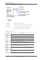
Message
36
Possible Causes
36
Solution
36
Connecting the Communications Cable Overview
37
9-Pin PLC Port to 25-Pin Serial Port
38
9-Pin PLC Port to 9-Pin Serial Port
39
25-Pin PLC Port to 25-Pin Serial Port
40
25-Pin PLC Port to 9-Pin Serial Port
41
RJ45 PLC Port to 9-Pin Serial Port
42
PLC WorkShop for Modicon
Table of Contents
24-Pin Military PLC Port to 25-Pin Serial Port
Chapter 3 – PLC WorkShop Basics
43
45
The landscape: PLC WorkShop window
47
Window Description
47
Title Bar
48
Menu Bar
48
Main Toolbar
49
Customize Toolbar
52
Instruction Bar
53
Inserting an Instruction Bar Item in a Program
54
Multiple Program Windows
54
Customizing Window Size and Position
55
Exceptions:
55
Floating Documentation Window
56
Status Line
56
Working with logic programs
58
Creating a New Logic Program
58
Fast PLC Connection - Connecting to a PLC
58
Preventing Fast PLC Connection
59
Opening an Existing Logic Program Offline or Online
60
Sharing Address Documentation
62
Combined
63
Combined Mode Save
65
Transfer Offline Program to Online
65
- 6 -
PLC WorkShop for Modicon
Table of Contents
Importing Documentation
66
Exporting Documentation
69
Delimited Documentation Text Format
72
Online Access Modes: Overview
74
Selecting the Initial Online Access Mode
74
Changing the Online Access Mode while online
76
Saving Logic Programs Overview
77
Save/Save As Online
78
Save Program As Offline
80
Automatic Backup
81
Setting Maximum Number of Backup Files
82
Opening a Backup File
83
Printing Logic Programs Overview
84
Print Logic
85
Print PLC Configuration
87
Print Registers
88
Print Documentation
89
Print Cross Reference
90
Print to a Text File
92
Print Disabled States
93
Print ASCII Messages
94
Configuring Documentation Font
95
Edit Title Page
97
- 7 -
PLC WorkShop for Modicon
Table of Contents
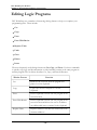
Editing Logic Programs
98
Cut
99
Copy
100
Paste
101
Paste With Rewire
101
Special Paste
103
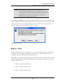
Replace Table
104
Undo
110
Clear
111
Delete
113
Insert
115
Introduction to Merge
117
Merge Program Procedure
117
Pick Destination Merge Program Dialog
118
Merge Program Choice Dialog
119
Merge 4x Check Box
120
4x Range
120
Merge 6x Check Box
120
6x Range
121
Merge ASCII message Check Box
121
Merge Traffic Cop Check Box
122
Merge Configuration Extension Check Box
122
Merge Solve Table Check Box
123
Merge Ladder Check Box
123
- 8 -
PLC WorkShop for Modicon
Table of Contents
Ladder Range
124
Merge Ladder Symbols
125
Error Checking on Edit or Add:
125
DX Table
125
Merge Logic Headers Check Box
126
Merge Address Documentation Check Box
126
Error Log Text File
126
Using WorkShop with FTVersionTrak
127
Getting Started with FTVersionTrak
127
Overview of Using FTVersionTrak in Workshop
128
FTVersionTrak Toolbar
129
Adding Files to the FTVersionTrak Repository
130
Getting Versions of a File
133
Checking Out Files
135
Checking In Files
137
Undoing a Check Out
138
Comparing WorkShop Files
139
Viewing File History
141
Electronically Signing WorkShop Files
143
Launching FTVersionTrak
144
Opening WorkShop Files
145
Saving WorkShop Files
148
Closing WorkShop Files
149
Operation Modes in FTVersionTrak
151
- 9 -
PLC WorkShop for Modicon
Table of Contents
FAQs about FTVersionTrak
152
Tips and Strategies for Team Programming
153
Chapter 4 – PLC WorkShop Setup Overview
155
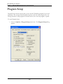
Program Setup
158
Application Setup
159
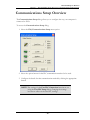
Communications Setup Overview
161
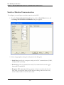
Serial or Modem Communication
162
Interface Boards
164
Connect Your PC to Ethernet
165
TCP/IP Communication Settings
166
IP Addresses
167
Network Scan
168
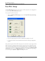
Fast PLC Setup
170
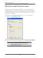
File Associated Communications
172
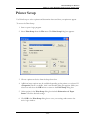
Printer Setup
173
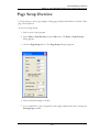
Page Setup Overview
175
Page Setup for Output to Text File
Chapter 5 – FasTrak Authentication and NT Security
176
179
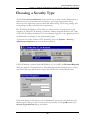
Choosing a Security Type
181
FasTrak Authentication Security Overview
183
FasTrak Authentication Log Setup
183
Security Setup
185
Administrator Options
186
- 10 -
PLC WorkShop for Modicon
Table of Contents
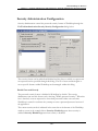
Security Administration Configuration
187
User Security Setup
191
NT Authentication Security Overview
194
Installing the Security Server
195
Workgroups and Domains
197
Adding Users and Groups to the Operating System
198
Configuring User Rights and Audit Policy
200
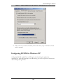
Configuring DCOM for NT Authentication Security
202
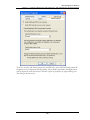
Configuring DCOM for Windows XP
205
Security Configurator Overview
208
Launching the Security Configurator
209
Chapter 6 – Auditing
217
Introduction to Activity Audit
219
Setup
219
Activity Audit Setup Dialog
221
Chapter 7 – PLC Configuration and Setup
227
PLC Configuration and Setup Overview
229
PLC setup
230
PLC Type Setup Overview
230
Changing PLC Types
230
PLC Configuration Overview
232
Configuring the Modicon 984 family of processors
Chapter 8 – Programming
234
279
- 11 -
PLC WorkShop for Modicon
Table of Contents
Programming Overview
281
Online versus Offline Programming
282
Using the Logic Editor
283
Logic Editor Overview
283
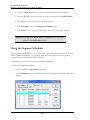
Using the Segment Scheduler
284
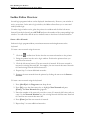
Ladder Editor Overview
286
Entering ladder instructions
288
Memory usage tables
298
Using the ASCII Message Editor
300
Text
302
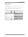
Data Format
303
Control Code
304
Repeat
305
Space
306
CR/LF
307
Flush
308
Clear {Edit box}
309
Clear {ASCII Message Editor box}
310
Copy
311
Close
312
Finding Logic
313
Find a Network
313
Find an Address or Tag
314
- 12 -
PLC WorkShop for Modicon
Table of Contents
Find a Ladder Symbol
315
Find a Ladder Item
315
Find an Address/Tag and Instruction
316
Find Keyword String in a Header
316
Find Next
317
Find Previous
317
Trace Coil and Untrace Coil
318
Trace Coil Overview
318
Untrace Coil
318
Displaying Traced Coils in Ladder
319
Data Window
321
Using the Data Window
321
Customizing the Display
322
Data Format
323
Editing Logic Programs
324
Cut
325
Copy
326
Paste
327
Paste With Rewire
327
Replace Table
329
Insert
336
Clear
337
Delete
339
- 13 -
PLC WorkShop for Modicon
Table of Contents
Hot Keys
340
Validate and Enter Logic
344
Disabling/Enabling Discrete I/O Overview
345
Disabling Data
345
Enabling Data
346
Show All Disabled Data
347
DX Zoom
348
Introducing DX Zoom
348
Using the Zoom Screen
349
Zoomable DX functions
350
Entering a Formula String
353
To Select the Data Format
354
To Change the Data Format of One Reference
354
Using the Cross Reference Table
355
Compare
357
File Program Compare
357
Using the Diagnostic Features
361
PLC Status Overview
361
EEPROM / Flash Memory
392
Displaying Processor Status
394
PLC Operations
395
Debugging Logic Programs (online)
396
Powerflow and Ladder Status (online)
397
Clearing Memory
398
- 14 -
PLC WorkShop for Modicon
Table of Contents
Chapter 9 – Documentation
401
Documentation Overview
403
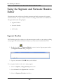
Using the Segment and Network Headers Editor
404
Segment Headers
404
Network Headers
405
All Headers
405
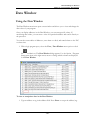
Documentation Window
408
Using the Documentation Window
408
Customizing the Display
409
Editing and Creating New Documentation
409
Deleting Documentation
412
Searching for an Address, Tag, Description, or Keyword
412
Documenting 4x BIT-of-WORD Addresses
415
Documenting in Ladder
417
Documenting in Ladder Overview
417
Assign Tags
417
Assign Addresses
417
Editing Documentation in Ladder Editor
418
Chapter 10 – Symbols
419
Symbols Overview
421
Using Symbols and Symbol Libraries in WorkShop
422
Activating Symbol Toolbars
422
Ladder Symbol Manager
422
- 15 -
PLC WorkShop for Modicon
Table of Contents
Using Toolbars
422
Customizing Symbol Toolbars
423
Programming with Symbols
425
Using the Toolbar
425
Symbol Pick Dialog
425
Documenting with Symbols
427
Edit Documentation window
Symbols Library Overview
427
429
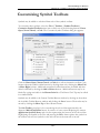
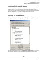
Accessing the Symbol Library
429
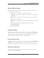
Editing, Copying, and Storing/Porting
430
Adding and editing symbols, animation, metafiles
431
On and Off State Edits
433
Animation Editor
433
Zoom In/Zoom Out
433
On-line Save By Parts
433
Chapter 11 – Instructions
435
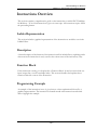
Instructions Overview
437
Ladder Representation
437
Description
437
Function Block
437
Programming Example
437
Relays, shorts, and coils
438
Relay Instructions
438
- 16 -
PLC WorkShop for Modicon
Table of Contents
Shorts
440
Coils
441
Bit Instructions Overview
446
Timers and Counters Overview
450
Timers
450
Up Counters
452
Down Counters
455
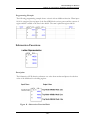
Arithmetic Functions Overview
458
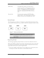
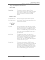
General Description
458
Addition Function
458
Subtraction Functions
461
Multiplication Function
464
Division Function (DIV)
466
Transfer and move instructions
471
Data Transfer Functions Overview
471
Indirect Block Read/Write Overview
489
FIFO Move Operations Overview
491
Logical Data Transfer Functions Overview
495
Logical Bit Operations Overview
506
General Description
506
Logical Compare (CMPR)
506
Logical Bit Modify (MBIT)
509
Logical Bit Sense (SENS)
512
- 17 -
PLC WorkShop for Modicon
Table of Contents
Logical Bit Rotate (BROT)
515
Status instruction
518
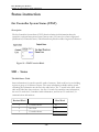
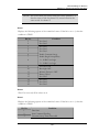
Get Controller System Status (STAT)
518
S901 - Status
518
S908 Status
529
S908 I/O Module Health Status Words
540
Compact 984 Status
548
Compact 984 I/O Module Health Status Words
553
Compact 984 I/O Communication Status Words
554
Modicon Micro PLC Status Table
554
Micro Health Status Words
560
Special instructions
569
DISA (Disabled Monitor System)
569
HIST (Discrete Logic Analyzer/Histogram)
569
SKIP
570
READ (ASCII Read Function)
572
WRIT (ASCII Write Function)
574
XMRD (Extended Memory Read)
577
XMWT (Write Extended Memory)
578
XMIT (Transmit) Description
581
Software Loadable Modules Description
593
CALL
594
EARS
595
EUCA
596
- 18 -
PLC WorkShop for Modicon
Table of Contents
FN10
596
HLTH (984 Health Status)
598
HSBY
598
MAP3
599
MBUS
600
MRTM (Multi-Register Transfer Module)
600
PEER
601
PID
601
Enhanced Executive Cartridge Instructions Overview
602
BLKT (Block-to-Table Move)
602
CKSM (CHECKSUM)
604
EMTH (Extended Math)
607
MSTR
612
PID2
614
TBLK (Table-to-Block Move)
615
Subroutines Overview
619
Additional Notes On Subroutines
620
JSR (Jump To Subroutine)
621
LAB (Label Subroutine)
623
RET (Return From Subroutine)
624
Miscellaneous Instructions
626
Instructions for the 351/455 Processors Overview
626
Using Implied References
632
- 19 -
PLC WorkShop for Modicon
Table of Contents
The 484 Compatibility Mode
633
16-Bit Signed and Unsigned Math Functions Overview
634
PCFL Overview
641
Input and Output Lines
642
Function Block
643
DIOH
645
Instructions for the Micro PLCs
646
- 20 -
Chapter 1 – Introduction
- 21 -
- 22 -
PLC WorkShop for Modicon
Chapter 1 – Introduction, Welcome to PLC WorkShop for Modicon
Welcome to PLC WorkShop for Modicon
PLC WorkShop for Modicon is a powerful Windows-based tool for programming the
Modicon family of programmable logic controllers (PLCs). Whether you are a novice or an
experienced programmer, this documentation has been constructed to help you begin using
PLC WorkShop quickly. We at FasTrak SoftWorks, Inc. have tried to assume little about
you, the user, except that when you have a question regarding this software you'll want it
answered. We hope this manual and the on-line help will answer those questions.
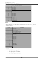
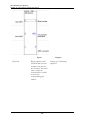
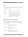
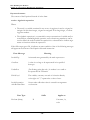
Chapter topics use names that will point you quickly to the specific information you want
to find. Chapters are titled as follows:
Section
Description
Introduction
Outlines help contents, Customer Support numbers and
necessary hardware and software to run PLC WorkShop.
PLC WorkShop
Quick Start Guide
Short, concise tips to get you started with PLC WorkShop
quickly and easily.
Installation
Guides you through the installation procedures for the
software and security.
PLC WorkShop
Basics
Describes PLC WorkShop for Windows features and helps
you move through the Windows environment.
PLC WorkShop
Setup
Provides specific guidelines in setting up and customizing
the software.
FasTrak
Authentication and
NT Security
Provides instructions for establishing and using a Password
Security Mode.
Auditing
Outlines options for tracking program and setting changes.
PLC Configuration
and Setup
Provides directions for configuring your processor to work
with PLC WorkShop.
Programming
Gives you solid understanding of PLC WorkShop’s easy to
use programming features.
Documentation
Shows you how to add symbols, labels and comments to
your logic programs.
- 23 -
PLC WorkShop for Modicon
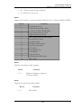
Chapter 1 – Introduction, Welcome to PLC WorkShop for Modicon
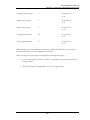
Section
Description
Symbols
Instructions for initializing and using graphical symbols for
programming and documentation.
Instructions
Gives detailed information about the PLC instructions
including programming examples.
Modicon Simulator
Outlines using the Modicon Simulator to test and debug
Modicon programs.
FTLogger/FTTrend
Shows you how to program the data Logger and Trender.
FTVersionTrak
Manages and tracks edits to change-sensitive data.
- 24 -
PLC WorkShop for Modicon
Chapter 1 – Introduction, Customer Support
Customer Support
It’s our goal that customers become proficient users of our software as quickly and easily as
possible. With that in mind, FasTrak makes available a number of support options.
Commonly asked questions can usually be answered with this user guide or by visiting our
website at www.fast-soft.com. Our website features easy-to-access FAQs, technical
resources, and system documentation.
For real-time how-to help and advanced troubleshooting, contact FasTrak’s customer
support center and speak directly with a technical support representative. Our trained
experts offer convenient, accurate and prompt assistance.
Customer Support
262.238.8088
Customer Support
Fax
262.238.8080
Email
[email protected]
Website
www.fast-soft.com
You may also forward questions, comments, and suggestions to:
FasTrak SoftWorks, Inc.
P.O. Box 240065
Milwaukee, WI 53224
- 25 -
PLC WorkShop for Modicon
Chapter 1 – Introduction, What is PLC WorkShop?
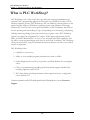
What is PLC WorkShop?
PLC WorkShop is one of the world’s most powerful and exciting programmable logic
controller (PLC) programming applications. Designed to run flawlessly in today’s 32-bit
Windows operating systems, PLC Workshop is the only Modicon software product on the
market that fully supports all Windows operating systems, from Windows 95 through
Windows XP. You can count on the speed and usability of PLC WorkShop, which allows
for fast uploading and downloading of logic, data updating, cross referencing, and printing.
Offering timesaving editing features and convenient at-a-glance views, PLC WorkShop
supports the entire line of Quantum™, Compact, TSX Compact, Momentum, 984™,
Micro, and 584™ Modicon PLCs. It’s easy to use, has built-in SCADA capabilities, and
the ability to track program changes with Activity Audit Trail. In addition, PLC Workshop
offers powerful security using NT authentication that incorporates one-time, server-based
security configuration.
PLC WorkShop offers:
1. Capability to use hot keys
2. Ability to view multiple programs simultaneously online or offline
3. Online Diagnostics Power Flow, Logic Status, and Data Window for viewing data
values
4. Choice of communications including Serial with modem support, Modbus Plus
including Applicom, and TCP/IP
5. PLC Status dialogs providing information about operational status, configuration,
error conditions, etc.
FormoreinformationonPLCWorkShopandotherFasTrakproducts,contact Customer
Support.
- 26 -
PLC WorkShop for Modicon
Chapter 1 – Introduction, Package Contents
Package Contents
Your PLC WorkShop package includes the items listed below. If any of these items are
missing or damaged, please contact FasTrak SoftWorks Customer Service.
l
One (1) PLC WorkShop CD
l
PLC WorkShop User's Guide
l
FasTrak-KEY to attach to your computer's parallel or USB port if applicable
- 27 -
PLC WorkShop for Modicon
Chapter 1 – Introduction, Hardware Requirements
Hardware Requirements
To install PLC WorkShop on your computer you need the following hardware.
l
A personal computer with an Intel Pentium 100 processor or higher
l
32 MB or more of RAM
l
An 800 X 600 VGA monitor with at least 256 colors
l
100 MB free disk space on your hard drive
l
A mouse is recommended, but not required
PLC WorkShop may not function properly on systems that are not 100% Intel
compatible. Certain other hardware components and peripherals can create
incompatibility problems.
- 28 -
PLC WorkShop for Modicon
Chapter 1 – Introduction, Software Requirements
Software Requirements
Youalsoneedthefollowingsoftware loadedonyourcomputerbeforeyouinstallPLC
WorkShop.
l
Windows 95, 98, NT, 2000, XP, Vista, or Windows 7
- 29 -
PLC WorkShop for Modicon
Chapter 1 – Introduction, Parallel Port Compatibility
Parallel Port Compatibility
Connecting the FasTrak-KEY to your computer's parallel or USB port is required to use PLC
WorkShop. Procedures for installing the FasTrak-KEY and PLC WorkShop are outlined
here. If your parallel port is not 100% IBM compatible, you may experience problems with
the FasTrak-KEY, which will prevent PLC WorkShop from functioning properly.
In most cases, you can correct the parallel interface incompatibilities by replacing the
parallel port with a 100% IBM compatible port or by adding a second printer adapter card.
NOTE: FasTrak SoftWorks is not responsible for problems that
result from using an incompatible parallel interface.
- 30 -
Chapter 2 – Installation
- 31 -
- 32 -
PLC WorkShop for Modicon
Chapter 2 – Installation, Install PLC WorkShop
Install PLC WorkShop
Beforeyoubegininstallation,reviewtheSystemRequirementssectionintheIntroduction
chapter.
To install PLC Workshop, turn your computer on and start Windows. A user name and
password may be required to log in to a computer network. If unsure, contact your
company’s System Administrator or IT representative.
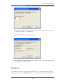
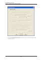
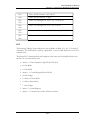
Follow these steps to install the software:
1. Insert the PLC Workshop CD in your computer’s CD-ROM drive.
2. The CD should start automatically. If not, click the Windows Start button. Then
click Run, and type x:\setup.exe, where x is the letter for the CD-ROM
drive.
3. Follow the instructions that appear on the screen.
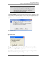
4. After making your selection, click Next. Installation begins. A message will appear
telling you that the PLC Workshop Installation Utility is loading.
- 33 -
PLC WorkShop for Modicon
Chapter 2 – Installation, Installing the FasTrak KEY
Installing the FasTrak KEY
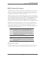
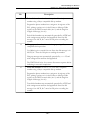
What is the FasTrak Key?
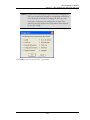
The WorkShop software is copy-protected with a device called the FasTrak-KEY, which is
included in your shipment. The FasTrak-KEY will be used for one of two purposes,
depending on your licensing agreement with FasTrak SoftWorks, Inc:
n
Single-user keyed license - Under this agreement, each FasTrak-KEY represents
one single-user license. The FasTrak-KEY must be attached to your computer
before you launch WorkShop. Otherwise, if a FasTrak-KEY is not detected, WorkShop will run in Demo mode with limited functionality.
n
Multi-user key on install only site license - Under this agreement, one FasTrakKEY is issued for your company. This key allows a certain number of installations
of WorkShop based on your site license agreement. The FasTrak-KEY must be
attached to your computer before you can install WorkShop, but can be removed
once WorkShop is installed.
To attach the FasTrak-KEY to your computer, connect the key to a parallel port (LPT1LPT3) or USB port on your computer, following the steps below. The FasTrak-KEY will
not interfere with normal port data transmissions, nor will it prevent you from creating
backup copies of the software.
NOTE: Installation of the FasTrak-KEY must be completed before
you run PLC WorkShop. If a FasTrak-KEY is not detected,
PLC WorkShop will run in Demo mode with limited
functionality.
- 34 -
PLC WorkShop for Modicon
Chapter 2 – Installation, Connecting the FasTrak-KEY
Connecting the FasTrak-KEY
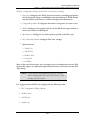
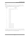
Follow the steps below to install the FasTrak-KEY.
1. Determine which port (parallel or USB) you will use to connect the FasTrak-KEY.
2. Disconnect other security devices or cables attached to that port.
3. Connect the FasTrak-KEY to the port.
4. Attach other cables to the FasTrak-KEY, if necessary. If the device attached to the
FasTrak-KEY is a parallel printer, make sure the printer is turned on before starting
PLC WorkShop.
NOTE: The FasTrak-KEY must be the first device attached to the parallel port. Other
devices or cables can subsequently be attached to the FasTrak-KEY.
- 35 -
PLC WorkShop for Modicon
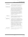
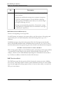
Chapter 2 – Installation, Troubleshooting the FasTrak-KEY
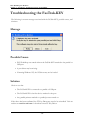
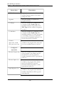
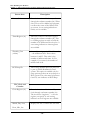
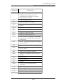
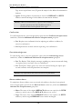
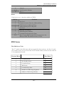
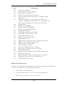
Troubleshooting the FasTrak-KEY
The following is an error message associated with the FasTrak-KEY, possible causes, and
solutions.
Message
Possible Causes
l
PLC WorkShop was started without the FasTrak-KEY attached to the parallel or
USB port.
l
A port driver may be missing.
l
If running Windows NT, the NT driver may not be loaded.
Solution
Check to see that:
l
The FasTrak-KEY is connected to a parallel or USB port.
l
The FasTrak-KEY is the first device attached to the port.
l
Any parallel printers attached to a parallel port are turned on.
If the above has been confirmed, the FT-Key Driver may need to be reinstalled. Visit our
website at www.fast-soft.com to download a new FT-Key Driver.
- 36 -
PLC WorkShop for Modicon
Chapter 2 – Installation, Connecting the Communications Cable Overview
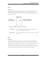
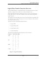
Connecting the Communications Cable
Overview
The communications cable connects a serial port of the computer to the PLC. This enables
programs and data to be transferred between the computer and the PLC. This cable has a 25pin connector on the computer end and either a 9- or 25-pin connector on the PLC end.
- 37 -
PLC WorkShop for Modicon
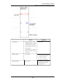
Chapter 2 – Installation, Connecting the Communications Cable Overview
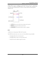
9-Pin PLC Port to 25-Pin Serial Port
- 38 -
PLC WorkShop for Modicon
Chapter 2 – Installation, Connecting the Communications Cable Overview
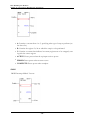
9-Pin PLC Port to 9-Pin Serial Port
- 39 -
PLC WorkShop for Modicon
Chapter 2 – Installation, Connecting the Communications Cable Overview
25-Pin PLC Port to 25-Pin Serial Port
- 40 -
PLC WorkShop for Modicon
Chapter 2 – Installation, Connecting the Communications Cable Overview
25-Pin PLC Port to 9-Pin Serial Port
- 41 -
PLC WorkShop for Modicon
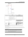
Chapter 2 – Installation, Connecting the Communications Cable Overview
RJ45 PLC Port to 9-Pin Serial Port
- 42 -
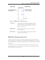
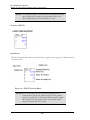
PLC WorkShop for Modicon
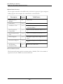
Chapter 2 – Installation, Connecting the Communications Cable Overview
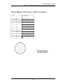
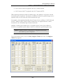
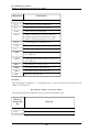
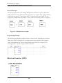
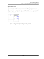
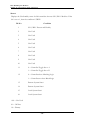
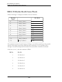
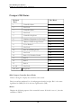
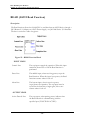
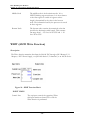
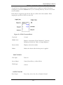
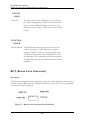
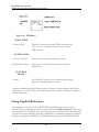
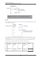
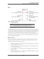
24-Pin Military PLC Port to 25-Pin Serial Port
PLC
Computer
24-pin Male
25-pin Female
C
1
J
2
K
3
L
6
P
7
Z
20
G
4
M
5
- 43 -
- 44 -
Chapter 3 – PLC WorkShop Basics
- 45 -
- 46 -
PLC WorkShop for Modicon
Chapter 3 – PLC WorkShop Basics, The landscape: PLC WorkShop window
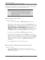
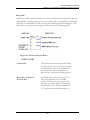
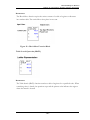
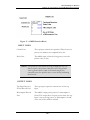
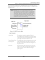
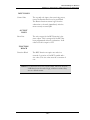
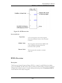
The landscape: PLC WorkShop window
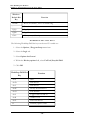
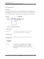
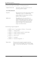
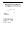
Window Description
The key features of the PLC WorkShop Window are defined below. More detailed descriptions follow.
Window
Feature
Function
Title Bar
Displays the name of
the application.
Buttons in the upper
right corners change
the window's size and
position.
Main Toolbar
Use to quickly access
frequently used menu
options.
Menu Bar
Use to select PLC
WorkShop functions.
FTVersionTrak
Toolbar
Use to perform version
control operations
using FTVersionTrak.
Instruction
Bar
Use to add instructions, new rows and
new networks to a
logic program.
Status Line
Displays information
about the operation in
progress.
Program Windows
Demonstrates that you
can display and edit
multiple logic programs
at the same time,
limited only by the size
of your computer's
memory.
- 47 -
PLC WorkShop for Modicon
Chapter 3 – PLC WorkShop Basics, The landscape: PLC WorkShop window
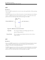
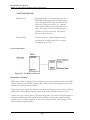
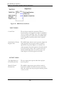
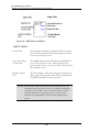
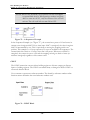
Title Bar
The Title Bar spans the top of the PLC WorkShop Window.
Use the Title Bar for three purposes:
l
l
l
To identify the application being used. In the example above, it's PLC WorkShop.
To move the window. A window or dialog box can be moved by clicking on the
title bar with the mouse pointer, holding down the left mouse button and dragging
to the desired location.
To change the size or position of the window. The following buttons appear on
the right side of the title bar:
Button Title
Location
Function
Minimize
Left box
Click the dash
button to reduce
window to an icon.
Maximize/Restore
Down
Middle
box
Click the window
button to enlarge
the window when
minimized, or
shrink the window
when maximized.
Close
Right
box
Click to exit
WorkShop.
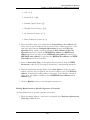
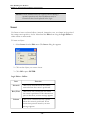
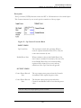
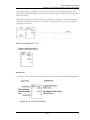
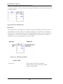
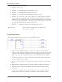
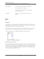
Menu Bar
The menu bar, located just below the title bar, identifies the names of the available PLC
WorkShop functions. To display the menu options for each function, click on the function
name. The menu options displayed may change depending upon the operation in progress.
For example, the Menu Bar illustrated below appears when you open PLC WorkShop.
- 48 -
PLC WorkShop for Modicon
Chapter 3 – PLC WorkShop Basics, The landscape: PLC WorkShop window
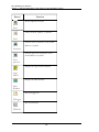
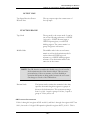
Main Toolbar
The Main Toolbar, located just below the Menu Bar in the PLC WorkShop Window,
displays a row of buttons that represent options you are likely to use frequently. Notice
that when you move your cursor over each button, its function appears on the Status Line
at the bottom of the window.
Button
Function
Attach directly to PLC
Fast PLC
Connection
Create a new program
New
Open an existing program
Open
Save the active program
Save
Cut the selection and put it on the
clipboard
Cut
Copy the selection and put it on the
clipboard
Copy
- 49 -
PLC WorkShop for Modicon
Chapter 3 – PLC WorkShop Basics, The landscape: PLC WorkShop window
Button
Function
Insert clipboard contents
Paste
Find a network, address, or symbol
Find
Find the next occurrence of the found
address or symbol
Find next
Find the previous occurrence of the
found address or symbol
Find
previous
Display the Logic Editor Window
Logic
Editor
Display the Data Window
Data
Window
Run FTLogger.exe
FTLogger
Run FTTrend.exe
FTTrend
- 50 -
PLC WorkShop for Modicon
Chapter 3 – PLC WorkShop Basics, The landscape: PLC WorkShop window
Button
Function
Display the Cross Reference Window
Cross
Reference
Display the Documentation window
Display the Traffic Cop window.
Display Modicon Simulator
Zoom in logic
Zoom In
Zoom out logic
Zoom Out
Insert New Network
Insert new
network
Append New Network
Append
new
network
Add a new row to a program
Append
row
- 51 -
PLC WorkShop for Modicon
Chapter 3 – PLC WorkShop Basics, The landscape: PLC WorkShop window
Button
Function
Enter and validate the active program
Enter
logic
Run/Stop
Puts the PLC in to Run Mode or Stops
the PLC (takes the PLC out of run
mode)
Returns cursor to arrow
Selection
cursor
Launches this help file
Help
topics
Display context-sensitive help for
currently selected item
Help
After a program has been opened, the Main Toolbar can be turned off and on by:
1. Selecting Toolbars from the View menu.
2. Selecting or clearing MainToolbar.
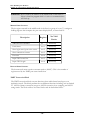
Customize Toolbar
You can customize the main toolbar. Customizing the main toolbar consists of selecting
which icons are displayed on the toolbar and specifying the order in which they are
displayed. For example, you could customize the main toolbar so that the 505 Simulator
- 52 -
PLC WorkShop for Modicon
Chapter 3 – PLC WorkShop Basics, The landscape: PLC WorkShop window
icon is displayed on the far left side of the toolbar. Or, you can add the Traffic Cop icon to
the toolbar.
To customize the main toolbar:
1. Right-click on the main toolbar and then click Customize.
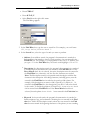
2. In the Customize Toolbar dialog box, specify which icons you want displayed on
the toolbar by moving icons to the Current toolbar buttons box from the Available toolbar buttons box. Move icons by dragging them to the appropriate box or
by selecting an icon and then clicking Add or Remove. Only the icons in the Current toolbar buttons box will be displayed on the toolbar.
3. You can specify the order in which icons are displayed on the toolbar by moving
icons in the Current toolbar buttons box. Icons displayed at the top of the Current toolbar buttons box are displayed on the left side of the toolbar. Move icons
by dragging them, or by selecting an icon and then clicking Move Up or Move
Down.
4. To add space between the icons on the toolbar, move the Separator icon from the
Available toolbar buttons box to the Current toolbar buttons box. The Separator
icon is moved like other icons.
5. If you want to return the toolbar to its default settings, click Reset. The icons are
reset to their default positions on the toolbar.
6. Close the Customize Toolbar dialog box when the icons are arranged as you want.
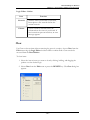
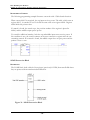
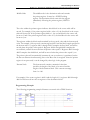
Instruction Bar
The default location of the Instruction Bar is at the top of the PLC WorkShop Window,
just below the Main Toolbar. The Instruction Bar and Toolbar are both dockable.
Instructions are divided into groups. By default, the Instruction Bar displays each group.
To display the instructions for a group, press the corresponding group button.
For example, to display the Math instructions, press the
- 53 -
group button.
PLC WorkShop for Modicon
Chapter 3 – PLC WorkShop Basics, The landscape: PLC WorkShop window
The Math group button remains selected and its instructions displayed until another group
button is pressed.
You can also choose to display the instructions for each group in its own Instruction Bar,
which will appear below the default Instruction Bar.
Each Instruction Bar can be turned on and off by:
1. Selecting Toolbars from the View menu.
2. Then select or deselect the Instruction Bar you wish to see.
Inserting an Instruction Bar Item in a Program
1. Click the desired instruction group button on the upper half of the Instruction Bar.
Instructions for that group will appear on the lower half of the bar.
2. Click the button showing the item you want to insert in the program. The item
attaches to the pointer when you move to the ladder editing area.
3. Move the pointer to the item insertion point on the ladder editing area and click the
left mouse button. The instruction is dropped into place.
4. Repeat step 3 each time you want to add the same item.
5. Click on the
button to return the pointer to an arrow.
Multiple Program Windows
PLC WorkShop gives you the ability to display more than one logic program window at a
time. You can open as many logic program windows as your computer's memory permits.
For example, you may wish to copy part of a logic program to another program. This will
save you programming time by not having to retype similar logic statements for each
program. To copy a part of one logic program to another, use the following procedure:
- 54 -
PLC WorkShop for Modicon
Chapter 3 – PLC WorkShop Basics, The landscape: PLC WorkShop window
1. Open both programs.
2. Arrange the logic program windows by selecting Tile or Cascade from the Window menu.
3. Highlight the data you want to copy to the other program by clicking the mouse and
dragging across the data.
4. Click Copy from the toolbar or from the Edit menu.
5. Move the pointer to the place you want to insert the data in the other program.
Click Paste from the toolbar or from the Edit menu.
Customizing Window Size and Position
By default, as WorkShop Logic, Documentation, Data, and Cross Reference (client)
Windows are opened, each Window slightly overlays the previously opened Window
(cascades). Once opened, these Windows may be resized and moved as desired.
When individual client Windows are closed, or when WorkShop is terminated, the position
and size settings of these Windows are saved and restored when the Windows are
subsequently reopened.
If the WorkShop Window is resized or monitor resolution changed, the positions of the
client Windows relative to WorkShop's client area are adjusted, maintaining the
proportions of the client Windows to the client area.
NOTE: Window position and size restoration occurs at the
application level and not the program level. For example, the
Documentation Window of Program A is restored to the
same position as the Documentation Window of Program B
even when both programs are open at the same time.
Exceptions:
l
If multiple client Windows of the same type are open for the same program, only
the first Window of a given type is restored. Any additional Windows of the same
type will cascade upon opening.
- 55 -
PLC WorkShop for Modicon
Chapter 3 – PLC WorkShop Basics, The landscape: PLC WorkShop window
l
If multiple client Windows of the same type are open when WorkShop terminates,
position and size settings are not restored.
l
Windows are always restored to their normal state. Minimized and maximized
states are not retained when Windows are closed.
Floating Documentation Window
The Floating Documentation Window shows documentation for the address on which the
parameter cursor is located. As the cursor moves, the information in the window changes.
The window can be configured to show either the description only, or the tag, description,
and comment. To configure the window, or to turn it on or off (it is off by default) use the
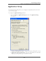
Application Setup dialog.
The window may be docked to a side of the PLC WorkShop Window.
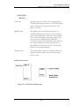
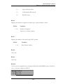
Status Line
The Status Line spans the bottom of the PLC WorkShop Window. It displays information
or describes the current operation on the left side. To display status line information for a
menu item or button, move the pointer over the item.
The right side of the Status Line displays the information listed below.
PLC
Route
The first shadowed box on the status line displays the route
defined for the active program. If the PLC route is a direct
serial connection to a PLC, then Direct is displayed. The
on-line PLC route is taken directly from the controller you
are connected to. The off-line PLC route informs you as to
the parameter saved in the PLC setup window for this
particular program.
Logic
Mode
Indicates whether you are programming on-line or off-line.
- 56 -
PLC WorkShop for Modicon
Chapter 3 – PLC WorkShop Basics, The landscape: PLC WorkShop window
OVR
Indicates cursor type, either overtype (OVR) or insert
(blank). In overtype mode characters to right of the cursor
are replaced with each new character typed. In insert mode
characters to the right of the cursor are moved one space
with each character typed.
NUM
Indicates if Num Lock is active for the keyboard. Thus
numbers will be typed when using the keypad, which is
usually on the right side of the keyboard. Num Lock is not
active when indicator area is blank.
CAP
Indicates if Caps Lock is active for the keyboard. When
typing, capital letters will appear if Caps is indicated. Caps
Lock is not active when indicator area is blank.
Valid
Ranges
Indicates legal address range for the instruction at the
current position.
- 57 -
PLC WorkShop for Modicon
Chapter 3 – PLC WorkShop Basics, Working with logic programs
Working with logic programs
Creating a New Logic Program
With PLC WorkShop, it’s easy to create a new program.
NOTE: New programs may be created in offline mode only. To
connect to a processor online, use the File / Open or File
/ Fast PLC Connect menu items.
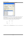
To create a new logic program and begin programming, do the following:
1. Select the File / New menu item, click the
the keyboard.
toolbar icon, or press [Ctrl+N] on
2. Select the PLC Type.
3. Press OK.
Fast PLC Connection - Connecting to a PLC
With PLC WorkShop, the PLC can be connected with a click of the mouse and existing
logic in the PLC can then be viewed and edited.
Prior to connecting the first time, the PLC connection must be set up. Refer to Fast PLC
Setup for more details.
To connect to a PLC online, select the File / Fast PLC Connection menu item or click
the
toolbar icon.
NOTE: Files cannot be loaded with Fast PLC Connection. To load a
file Online, use the Open Program dialog, which is
accessed through the File / Open menu item.
- 58 -
PLC WorkShop for Modicon
Chapter 3 – PLC WorkShop Basics, Working with logic programs
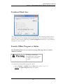
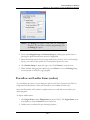
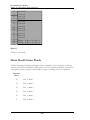
Preventing Fast PLC Connection
To prevent connection by Fast PLC:
1. Select the Options / Application Setup menu item. The Application Setup
dialog appears.
2. Deselect the Enable Fast PLC Connection check box.
- 59 -
PLC WorkShop for Modicon
Chapter 3 – PLC WorkShop Basics, Working with logic programs
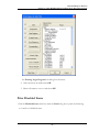
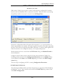
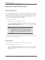
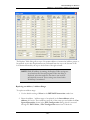
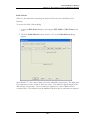
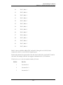
Opening an Existing Logic Program Offline or Online
You can open an existing logic file to edit or update program information in either online or
offline mode. Logic programs may contain one or more of the following: logic and data,
tags, headers, and descriptions and comments. Several programs may be open at one time
without losing memory contents.
Editing or modifying a program
online may produce unexpected or
hazardous results.
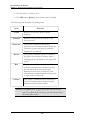
To open an existing program:
1. Select the File / Open menu item, click the
The Open Program dialog appears.
toolbar icon, or press [Ctrl-O].
NOTE: The last four files that were opened are saved and listed at
the bottom of the File menu. When one of these files is
selected, the Open Program dialog automatically opens
with the file that has been selected.
- 60 -
PLC WorkShop for Modicon
Chapter 3 – PLC WorkShop Basics, Working with logic programs
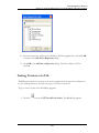
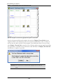
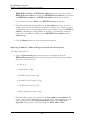
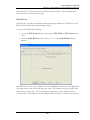
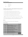
2. Click Browse. The Open dialog appears.
3. Change drives and/or directories, if necessary, to find the program you wish to
open. You can open *.FMD (PLC WorkShop 32-bit) files, *.FTK (PLC WorkShop
16-bit) files, *.PGR (PLC WorkShop DOS) files, or *.CFG (ModSoft configuration)
files.
4. Click on the program name in the File Name scroll box and click OK. The name of
the program appears in the Program File and Address Documentation fields of
the Open Program dialog. If a different documentation program is desired, it may
be linked via the Share Address Documentation function.
5. In the Program Type group box, select Offline or Connect to PLC. If Connect
to PLC is selected, the previously saved communication port can be used or a new
communication port selected by clicking the Setup button and other options may
be chosen, such as Transfer Logic to PLC - Transfers all logic and data areas to
the PLC, and loads documentation.
6. Click OK or press [Enter] to open the program.
- 61 -
PLC WorkShop for Modicon
Chapter 3 – PLC WorkShop Basics, Working with logic programs
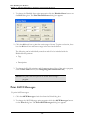
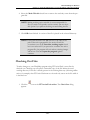
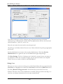
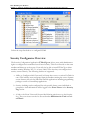
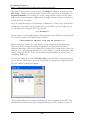
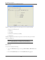
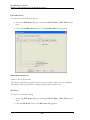
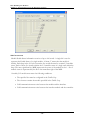
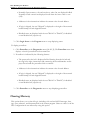
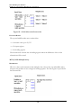
Sharing Address Documentation
When a file is configured, a database file that holds and sorts all documentation can be
specified. Multiple users can simultaneously modify documentation for the same file, thus
regular updates can be scheduled to get the latest documentation within the database.
Documentation can be imported from *.FMD (PLC WorkShop 32-bit) files, comma or tab
separated. Conversely documentation can be exported from the database file into a text file
or *.PGR (PLC WorkShop DOS) files.
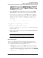
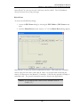
To set up shared documentation:
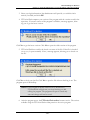
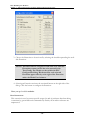
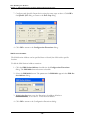
1. Access the Open Program dialog by selecting the File / Open menu item.
2. Click Browse to select a file.
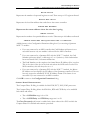
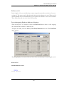
3. Click the Advanced button of the Open Program dialog. The Share Address
Documentation dialog appears.
4. Enter the share address documentation program name and path in the Shared File
and Path field to create a new file or select Browse to locate an existing file. If creating a new file, when prompted, click Yes to confirm that it should be created.
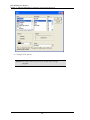
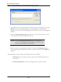
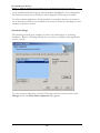
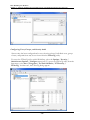
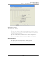
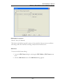
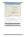
5. Click Next. The following screen appears.
- 62 -
PLC WorkShop for Modicon
Chapter 3 – PLC WorkShop Basics, Working with logic programs
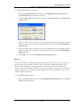
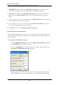
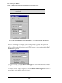
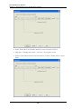
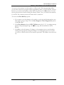
6. Enter the refresh rate (time lag between updates from other users of the database).
Valid times are from 1 to 1440 minutes.
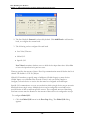
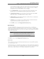
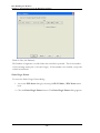
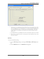
7. Click Next. The following screen appears.
8. Click Finish. The Open Program dialog reappears with the new filename and path
for the address documentation.
Combined
If you have an existing file and want to connect online, to a controller that the program
resides in, you can use the Combined feature to go online faster. Combined also allows for
- 63 -
PLC WorkShop for Modicon
Chapter 3 – PLC WorkShop Basics, Working with logic programs
any online edits of Ladder, TCOP, ASCII message, Configuration Extension, Modbus
Ports, ASCII Ports and Segment Scheduler to be made to the PLC and Databases at the
same time which allows for a faster online save. You select Combined Mode in the Open
dialog by selecting the Combined checkbox.
For Combined Mode to work, the file that is used to attach online is assumed to be an
exact match with the PLC program. If the ladder or basic configuration does not match,
connection online is not allowed. Even if ladder, Coils Used (including Battery coil),
configuration, Modbus Ports, State Table (Registers) match after attach, the following parts
could still be different:
Configuration:
l
DAT Loadables
l
TCOP
l
Configuration Extension
l
Solve Table
l
ASCII Port Parameters
l
EXE Loadables
ASCII:
l
ASCII Message
Data:
Never checked
Combined Mode does not allow changes to the configuration memory (Configuration. Ext.,
Segment, Configured Quantities, Adding or deleting Loadables etc.), proceeding with this
action removes Combined Mode and requires a full online save.
l
Clearing PLC memory is also not allowed in Combined Mode. Proceeding with this action
removes Combined Mode and requires a full online save.
If Combined Mode has been canceled, and a save is attempted, save reads from the PLC
memory, not from offline.
If the PLC is in Dim-awareness the Combine Mode will produce an error.
- 64 -
PLC WorkShop for Modicon
Chapter 3 – PLC WorkShop Basics, Working with logic programs
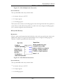
Combined Mode Save
The 4 top check boxes are always checked and disabled. The complete program is always
saved. Data values for 0x through 6x are an option. If data is not saved they retain their
previous values from the offline file. The Save 6x Registers check box is only enabled if
6x registers exist in the PLC.
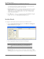
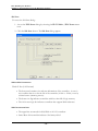
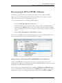
Transfer Offline Program to Online
PLC WorkShop allows you to transfer an existing offline logic file to an online
Modicon controller.
Editing or modifying a
program online may produce
unexpected or hazardous
results.
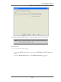
To transfer an existing offline program to online:
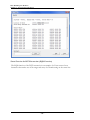
1. Select Transfer -> Online from the File menu or press [Ctrl+T].
Result: The Open Program dialog box appears.
- 65 -
PLC WorkShop for Modicon
Chapter 3 – PLC WorkShop Basics, Working with logic programs
2. Select OK to Transfer.
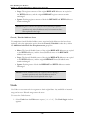
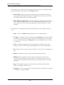
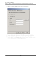
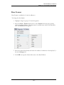
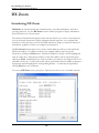
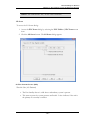
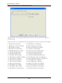
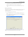
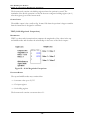
Importing Documentation
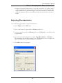
Use the following procedure to import documentation.
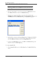
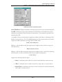
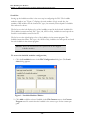
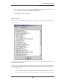
1. Select Import from the File menu. The Import dialog box appears.
2. Select the type of file to import from the Format combo box.
3. Type the program name in the Filename field, or click Browse to search from valid
program names.
4. Click OK to import the program.
- 66 -
PLC WorkShop for Modicon
Chapter 3 – PLC WorkShop Basics, Working with logic programs
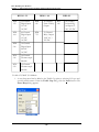
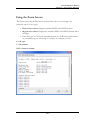
The Include group box contains three documentation items: Tags, Descriptions, and
Headers, which are read when files are imported. Not every item is valid for every import
format. Additionally, not every format allows these items to be manually selected and
unselected. The items loaded during the import are indicated in this group box.
l
Select the Tags check box to include them in the documentation import.
l
Select the Descriptions check box to include them in the documentation import
l
Select the Headers check box (labeled "Description Comments" under the Taylor ProWORX Symbol .fis Documentation File format) to include them in the
documentation import.
NOTE: For most import formats, these options are checked by
default. However, the check box may be selected or
unselected under some import formats. When importing
Delimited Documentation Text Files, Headers must be
imported independently of Tags and Descriptions.
The Format combo box of the Import dialog offers several file types:
l
FasTrak WorkShop documentation (*.fmd) - This selection reads documentation from another WorkShop program
l
FasTrak DOS (PLC WorkShop) - This selection reads documentation from a
DOS WorkShop program.
- 67 -
PLC WorkShop for Modicon
Chapter 3 – PLC WorkShop Basics, Working with logic programs
l
Taylor ProWORX/ASCII .fil Documentation File - This selection reads documentation exported by ProWORX into the Taylor ASCII *.FIL format. The ProWORX "Descriptor" is loaded into the WorkShop Description, the "Short
Comment", "Page Title" and "Long Comment" are written in that order to the
WorkShop Description Comment.
l
Taylor ProWORX Symbol .fis Documentation File - This selection reads symbol documentation exported by ProWORX into the Taylor *.FIS format. The ProWORX "Symbol" is written to the Workshop Tag; the "Descriptor" is written to
the WorkShop Description, the "Short Comment", "Page Title" and "Long Comment" are written in that order to the WorkShop Description Comment.
l
Modsoft Text Export (Address/Symbol/Descriptor) - This selection reads
the Modsoft Address, Symbol and Descriptor documentation exported into an
ASCII text file.
l
Modsoft Text Export (Segment & Network Comments) - This selection
reads the Modsoft Segment and Network Comment documentation exported into
an ASCII text file.
l
DMC LadderMaster (ASCII Export) - This selection reads documentation
exported by DMC into an ASCII file.
l
Delimited Documentation Text File - This selection reads documentation previously exported by PLC WorkShop into an ASCII file.
l
4x Register Text File - This selection reads 4x register data previously exported
by PLC WorkShop into an ASCII file.
The Text Import Delimiter group box contains the two delimiter characters (commas or
tab characters), which may be used in certain text import files. These delimiter characters
are used to separate fields within each record of these files. The delimiter character may be
selected for Delimited Documentation Text File and 4x Register Data Test File
formats only.
Use the Delimited Documentation Text File format to merge tags, descriptions, and/or
headers from the ASCII text files exported from PLC WorkShop into the selected file. You
must also select comma or tab delimited records with the following format:
l
Characters 1 – 5 or 6 contain the 5 or 6-digit Modicon address.
l
Character 6 is the comma or tab character.
l
Character 8 and beyond is the variable length tag, followed by the comma or tab
character, the variable length description, and a carriage return.
- 68 -
PLC WorkShop for Modicon
Chapter 3 – PLC WorkShop Basics, Working with logic programs
l
Headers are imported independently of tags and descriptions. If a header contains
a carriage return, double quote characters, or commas, it is surrounded by double
quotes. Headers have a maximum length of 16k ASCII characters. A header with
no special characters will be stored without double quotes and read to the end of
its line.
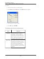
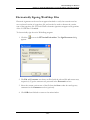
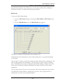
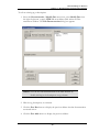
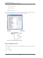
Exporting Documentation
Use the following procedure to export documentation.
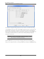
1. Select Export from the File menu.
2. Select a file format for export from the Format combo box.
3. Type the program name in the Filename field, or click Browse to search from valid
program names.
4. Select the parts of documentation to export: Tags, Descriptions, or Headers.
Then determine which delimiter format to use. The delimiter is used to separate the
types of documentation (Tags, Descriptions or Headers).
5. Click OK to export the program.
- 69 -
PLC WorkShop for Modicon
Chapter 3 – PLC WorkShop Basics, Working with logic programs
The Format combo box of the Export dialog offers several file types to which documentation can be written. Documentation to FasTrak's PLC WorkShop DOS package can be
written directly to the native data files. In addition, documentation can be exported into
file formats, which in turn can be imported by competitor’s packages.
l
FasTrak DOS (PLC WorkShop) - This selection writes documentation to a PLC
WorkShop DOS program documentation file.
l
Delimited Documentation Text File - This selection writes documentation,
which can be edited externally, then imported back into PLC WorkShop.
l
4x Register Text File - This selection writes 4x register data, which can be
edited externally then imported back into PLC WorkShop.
l
Taylor ProWORX/ASCII .fil Documentation File - This selection writes documentation into the Taylor ASCII *.FIL format, which can be imported by ProWORX. The WorkShop Description is exported as the ProWORX "Descriptor",
the WorkShop Description Comment is split into the "Short Comment" and "Page
Title". The ProWORX "Long Comment" is stored in a separate ProWORX database file to which the Export process cannot write. Therefore, the "Long Comment" portion of the Description Comment cannot be exported even if it was
originally imported from a ProWORX *.FIL.
l
Taylor ProWORX Symbol .fis Documentation File - This selection writes symbol documentation into the Taylor *.FIS format, which can be imported by ProWORX. The WorkShop Tag is exported as the ProWORX "Symbol", the
Description is exported as the ProWORX "Descriptor", and the WorkShop
Description Comment is split into the "Short Comment" and "Page Title". The
ProWORX "Long Comment" is stored in a separate ProWORX database file to
which the Export process cannot write. Therefore, the "Long Comment" portion
of the Description Comment cannot be exported - even if it was originally
imported from a ProWORX *.FIS.
The Include group box contains three documentation items: Tags, Descriptions, and
Headers, which are written when files are exported. Not every item is valid for every
export format. Additionally, not every format allows these items to be manually selected
and unselected. The items written during the export are indicated in this group box.
NOTE: When exporting Delimited Documentation Text Files,
headers must be exported independently of tags and
descriptions. Selecting Header when exporting this format
will disable Tags and Descriptions, and vice versa.
- 70 -
PLC WorkShop for Modicon
Chapter 3 – PLC WorkShop Basics, Working with logic programs
l
Click the Tags check box to include them in the documentation export. For most
export formats, this option is checked by default. However, this check box may be
selected or unselected under some export formats.
l
Click the Descriptions check box to include them in the documentation export.
For most export formats, this option is checked by default. However, this check
box may be selected or unselected under some export formats.
l
Click the Header check box to include them in the documentation export. For
most export formats, this option is checked by default. However, this check box
may be selected or unselected under some export formats.
l
The Delimiter group box contains the selection of two delimiter characters (commas or tab characters), which may be used in some text exports files. These characters are used to separate fields within each record of these files. The delimiter
character may be selected for Delimited Documentation Text File and 4x Register Data Text File formats only.
WhentheTaylor ProWORX/ASCII.filDocumentationFileorTaylor ProWORX
Symbol.fisDocumentationFileformatsareselected,the DescriptorFieldWidthand
NumberofDescriptorFieldscomboboxes appearwithintheTaylorProWORX groupbox
below.
These settings correspond to the same options used in ProWORX to specify the number
and length of ProWORX Descriptor lines. It is important to select the matching settings so
the exported *.FIL or *.FIS files are written in the proper size.
- 71 -
PLC WorkShop for Modicon
Chapter 3 – PLC WorkShop Basics, Working with logic programs
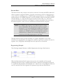
Delimited Documentation Text Format
Documentation exported as delimited text files may be edited in any text editor or
spreadsheet application that supports the *.TXT extension. When importing and exporting
to this format, headers will be imported and exported as its own file separate from tags and
descriptions. After exporting the files, tags, descriptions, and headers can be edited and
updated before importing back into the program. While editing delimited documentation,
the proper format must be retained for the documentation to be imported correctly.
Tags and Descriptions
Tags and descriptions are exported as comma- or tab-separated values in the following format:
address<delimiter> tag<delimiter>description
Descriptions that break across multiple lines are also separated into their own comma- or
tab-separated values:
Example:
00001, TAG, This description, is on three, lines
00002, TAG2, Two line, description
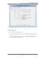
Headers
Headers are exported to their own files as comma- or tab-separated values. Network
headers, segment headers, and the Title Page may be exported, edited, and imported
in the following format:
Title<delimiter>
Title description<delimiter>
Seg 1<delimiter>
Segment 1 header<delimiter>
Net 1<delimiter>
Network 1 header<delimiter>
Headers that contain newline, double quote characters, commas, or other special characters
are surrounded by double quotes inside the delimiters. Headers that do not contain any of
these characters contain no double quotes and are only separated by their delimiters.
Headers that break across multiple lines are also separated into their own delimited values:
Example
Title,
- 72 -
PLC WorkShop for Modicon
Chapter 3 – PLC WorkShop Basics, Working with logic programs
“The first line of the title has a word wrapped in double quotes. ““word”””,
“The second line has a comma in it, so it needs to be wrapped in double quotes”,
The third line does not have any special chars in it,
Segment 1,
Segment 1 header,
Net 1,
Network 1 header,
Net 2,
Network 2 header. This happens,
To be on 2 lines.,
- 73 -
PLC WorkShop for Modicon
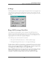
Chapter 3 – PLC WorkShop Basics, Online Access Modes: Overview
Online Access Modes: Overview
PLC WorkShop provides modes for editing ladder logic online, and for monitoring logic
online without the risk of inadvertent edits.
l
Program Mode: allows online editing
l
Monitor Mode: prevents online editing
l
Auto Monitor Mode: allows an online editing session, then switches (after a userdefined period of inactivity) to Monitor Mode.
NOTE: The access modes apply only when online. Editing is always
possible when offline.
In the event of an unintended edit offline, the backup files that PLC WorkShop automatically creates can be used.
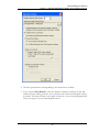
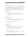
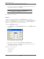
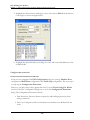
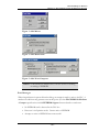
Selecting the Initial Online Access Mode
1. Select the Options/Application Setup menu option to display the Application
Setup dialog.
- 74 -
PLC WorkShop for Modicon
Chapter 3 – PLC WorkShop Basics, Online Access Modes: Overview
2. Click the option button corresponding to the desired Access Mode.
3. If you selected Auto Monitor, enter the number of minutes of inactivity that will
indicate that the editing session is over, and cause the switch from Program to Monitor mode. The time selected is the length of inactivity - the user may program indefinitely as long as it is in an uninterrupted session.
- 75 -
PLC WorkShop for Modicon
Chapter 3 – PLC WorkShop Basics, Online Access Modes: Overview
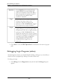
Changing the Online Access Mode while online
The current access mode is shown in the title bar.
l
If you attempt to edit online while in Monitor mode, a dialog appears informing
you of the fact. If you are in Auto Monitor mode and the programming session has
timed out, the dialog includes an option to re-enable Program Mode.
l
It is also indicated by the presence or absence of a check mark next to the Program/Program Mode menu option.
To change the mode while online:
1. Select the Program/Program Mode menu option. If Program Mode is active
(indicated by a check mark) this switches PLC WorkShop to Monitor Mode. If PLC
WorkShop is in Monitor Mode, this switches to Program Mode.
- 76 -
PLC WorkShop for Modicon
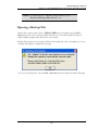
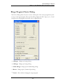
Chapter 3 – PLC WorkShop Basics, Saving Logic Programs Overview
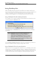
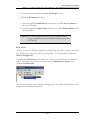
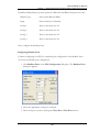
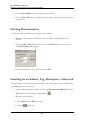
Saving Logic Programs Overview
Use the Save Program command to save the active program contents with its existing
name. To save the active logic program:
1. Click
on the Toolbar or select Save Program from the File menu or press
[Ctrl+S], and a previously saved logic program is saved.
2. If the program has not been previously saved, the Save As dialog box appears.
Select the desired location to save the program, and type in a name for the program
in the Filename field.
3. Click Save or press [Enter] to save the program.
4. If you select a file name that already exists in that directory, a message appears with
options. Select from the following options:
l
YES saves the updated program with the current name, overwriting the previous
version.
l
NO cancels the save procedure.
- 77 -
PLC WorkShop for Modicon
Chapter 3 – PLC WorkShop Basics, Saving Logic Programs Overview
NOTE: You must validate logic before saving. If you have not done
so, a message appears stating changes to logic have not been
validated or entered. Changes cannot be saved until logic has
been validated and entered. Click Validate Logic on the
toolbar,
or select Validate and Enter Logic from the
Program menu. Complete necessary changes to logic and
try to save the program again.
Save/Save As Online
Usethe onlineSave Program commandto saveall theactive programcontents withits existing
nameor partsof anexisting logicprogram. Oneor moreof the followingparts canbe saved:
l
PLC Program
l
Save Ladder Headers
l
Save Address Documentation (Tags, Descriptions, Comments and Headers)
l
Save 6x Registers
To save the active logic program:
1. Click
on the Toolbar or select Save Program from the File menu CTRL+S.
The Save dialog box appears.
- 78 -
PLC WorkShop for Modicon
Chapter 3 – PLC WorkShop Basics, Saving Logic Programs Overview
2. Deselect the parts of the program you do not wish to save.
3. If the program has not been previously saved or you wish to change the file name,
click the Browse button, and type in a name for the program in the Program File
field.
4. Click OK or press ENTER to save the program.
5. If you select a file name that already exists in that directory, a message appears with
options. Select from the following options:
l
YES – saves the updated program with the current name, overwriting the previous version.
l
NO – cancels the save procedure.
NOTE: You must validate logic before saving. If you have not done
so, a message appears stating changes to logic have not been
validated. or entered. Changes cannot be saved until logic
has been validated and entered. Click Validate Logic on
the toolbar,
or select Validate and Enter Logic from
the Program menu. Complete necessary changes to logic
and try to save the program again.
- 79 -
PLC WorkShop for Modicon
Chapter 3 – PLC WorkShop Basics, Saving Logic Programs Overview
If you are working online and saving your changes, a warning message appears stating that
logic in the active PLC program has been modified, and asks if you wish to save the logic
in addition to tags and documentation.
Click Yes to save logic, tags, and documentation. Click No to save documentation and
tags only. Cancel aborts the save procedure.
If you are saving documentation to an online logic program and the last network header
exceeds the number of networks/addresses, an error message appears.
Editing or modifying a
program online may produce
unexpected or hazardous
results.
Save Program As Offline
Use Save Program As to save the active logic program with a different program name.
This is useful when maintaining the original without changes. For example, open file
ABC.FMD, make changes, select Save Program As, and save the program as DEF.FMD.
Now you have two files, ABC.FMD retained its same condition before you opened it, and
DEF.FMD that contains changes made to ABC.FMD.
NOTE: You must validate logic before saving. If you have not done
so, a message appears stating that changes to logic have not
been validated or entered. Changes cannot be saved until
logic has been validated and entered.
Click Validate Logic on the toolbar,
or select
Validate and Enter Logic from the Program menu.
Complete necessary changes to logic and try to save the
program again.
To save a logic program with a new file name:
1. Select Save As from the File menu. The Save As dialog box appears.
2. In the Save As dialog box, click options in the necessary group boxes to designate a
location to save the logic program.
- 80 -
PLC WorkShop for Modicon
Chapter 3 – PLC WorkShop Basics, Saving Logic Programs Overview
3. Click OK or press ENTER. Your file is saved with its new name.
4. If you select a file name that already exists in that directory, a message appears with
options. Select from the following options:
l
YES saves the updated program with the current name, overwriting the previous version.
l
NO cancels the save procedure.
NOTE: If you are saving documentation to an online program, please
see Saving Online.
Automatic Backup
WorkShop automatically maintains a rolling set of backup files each time a PLC program is
saved. When a PLC program is saved, the previous version is renamed to the existing file
name with BAK001appended. Any existing backup files are renamed with a number one
higher, up to the number of backups that have been defined. See Setting Maximum
Number of Backup Files.
For example, if a program named MyProg.fmd is saved, and the number of backups is set to 5:
The current file
Becomes
MyProg.fmd
MyProgBAK001.fmd
MyProgBAK001.fmd
MyProgBAK002.fmd
MyProgBAK002.fmd
MyProgBAK003.fmd
MyProgBAK003.fmd
MyProgBAK004.fmd
MyProgBAK004.fmd
MyProgBAK005.fmd
MyProgBAK005.fmd
Is not saved
- 81 -
PLC WorkShop for Modicon
Chapter 3 – PLC WorkShop Basics, Saving Logic Programs Overview
Setting Maximum Number of Backup Files
The default maximum number of backup files maintained for each *.FMD file is five. This
value may be set to any integer between 0 and 999. This setting applies to all *.FMD files
and is not specific to only the current file.
To specify the maximum number of backup files:
1. Select the Options / Application Setup menu item. The Application Setup
dialog appears.
2. Enter a value in the Number of Backup Files Saved edit box.
- 82 -
PLC WorkShop for Modicon
Chapter 3 – PLC WorkShop Basics, Saving Logic Programs Overview
NOTE: To deactivate the *.FMD file backup feature, set the
Number of Backup Files Saved to zero.
Opening a Backup File
Backup files (whose names end in _BAKxxx.FMD) may be opened using the File /
Open menu item. Once opened, backup files may be viewed and edited just like the
original ladder program from which they were created.
Backup files cannot be saved again with the same backup file name. Attempting to re-save
a backup file displays a similar error message:
To re-save the backup file, select the File / Save As menu item and enter another file name.
- 83 -
PLC WorkShop for Modicon
Chapter 3 – PLC WorkShop Basics, Printing Logic Programs Overview
Printing Logic Programs Overview
PLC WorkShop provides you with a number of print features that allow customization of your printouts.
Before you can print, open a logic program. Make certain that you have loaded the correct
print drivers for your printer through the Windows Control Panel. If you have questions
regarding loading print drivers, consult your printer’s user’s manual and the Windows
User’s Guide.
To print logic programs and/or documentation:
1. Access the appropriate Print dialog by selecting either Print or Print Preview
from the File menu or by pressing [Ctrl+P.
- 84 -
PLC WorkShop for Modicon
Chapter 3 – PLC WorkShop Basics, Printing Logic Programs Overview
2. Click on the check boxes that correspond to the items you want to print. For each
item selected, you can choose sort options and the information you want to include
for reports. The Selected Items window displays the print range of each print item
to be printed.
Print Logic
Select the Logic check box within the Print dialog to print the following:
l
All ladder logic
l
Selected ladder logic
l
Inline Xref
l
Ladder with Addresses, Tags, Descriptions, or Headers
l
Multiple or single networks per page
To display the Print Logic options:
1. Access the appropriate Print dialog by selecting either Print or Print Preview from
the File menu or by pressing [Ctrl+P].
2. Click the Logic button within the Print dialog. The Print Logic dialog appears.
- 85 -
PLC WorkShop for Modicon
Chapter 3 – PLC WorkShop Basics, Printing Logic Programs Overview
The Print Logic dialog box determines which items are printed.
3. Configure the following options for the Logic printout:
l
Click the Print All check box to print the entire range of ladder
selected.
l
To print a selection range, deselect the Print All check box and enter a
range in the associated Segment, Network range box.
l
If you selected to print By Segment, the from and to segment and network numbers can be entered. Each segment's starting network will
always start with 1.
l
If the Continuous by Segment radio button is selected, only from and
to segment numbers can be entered. The first network in the first segment is numbered 1. All other networks are numbered continuously.
- 86 -
PLC WorkShop for Modicon
Chapter 3 – PLC WorkShop Basics, Printing Logic Programs Overview
The first network of the next segment is numbered 1 plus the preceding
segment's last network number.
l
If Continuous radio button is selected, only from and to network
numbers can be entered. The first network in the first segment is numbered 1. All other networks are numbered continuously. The first network of the next segment is numbered 1 plus the preceding segment's
last network number.
l
When selecting Networks per Page as Single or Multiple, use the following information: When printing Single Networks per Page, each
network begins on a new page. When printing Multiple Networks per
Page, as many networks that can fit on a single page will be printed.
However, if the network is not the first network on the page and the
network is broken across more than one page but can fit on a single page
and if it would start a new page, then the network begins on a new page.
The intent is to keep the entire network on one page whenever possible.
l
To change the Tag, Description, and Comments printed font of the
active program, click the Doc Font button. (See Configuring Documentation Font.)
NOTE: The print selection options are stored when saving a
program.
Print PLC Configuration
Click the Configuration check box from the Print dialog to print the following:
l
PLC Configuration
l
Traffic Cop
l
ASCII Ports
l
Modbus ports
l
Configuration Extensions
- 87 -
PLC WorkShop for Modicon
Chapter 3 – PLC WorkShop Basics, Printing Logic Programs Overview
l
Segment Scheduler
l
Segment Summary
To change the PLC Configuration properties click the PLC Configuration button on the
Print dialog box. The Print PLC Configuration dialog box appears.
Click the Print All check box to print the entire range of items. To print a selection,
deselect the Print All check box and select the items to include.
To change the Tag, Description, and Comments printed font of the active program, click
the Doc Font button. (See Configuring Documentation Font.)
NOTE: The print selection options are stored when saving a
program.
Print Registers
Click the Register check box from the Print dialog box to print the following:
l
0x, 1x, 3x, 4x and/or 6x
To change the Register properties click the Register button on the Print dialog box. The
Print Register dialog box appears.
- 88 -
PLC WorkShop for Modicon
Chapter 3 – PLC WorkShop Basics, Printing Logic Programs Overview
1. Click the All check box to print the entire range of items. To print a selection, deselect the All check box and enter a range in the associated edit box.
2. The tags and descriptions can be individually turned on or. To include with the Register print out select the appropriate check box under Include.
3. To change the Tag, Description, and Comments printed font of the active program,
click the Doc Font button. (See Configuring Documentation Font.)
NOTE: The print selection options are stored when saving a
program.
Print Documentation
Click the Documentation check box from the Print dialog box to print the following:
l
0x, 1x, 3x, 4x and/or 6x
l
Register Tags, Descriptions, Comments, and Values
- 89 -
PLC WorkShop for Modicon
Chapter 3 – PLC WorkShop Basics, Printing Logic Programs Overview
To change the Documentation properties click the Documentation button on the Print
dialog box. The Print Documentation dialog box appears.
Click the register check box to print the entire range of registers.
The Register Tags, Descriptions, Comments, and Values can be individually turned on
and off. To include with the Documentation print out select the appropriate check box
under Include.
The sort order for documentation print can be based on Address, Tag, or Description.
To change the Documentation print sort orders select the appropriate check box under
Sort Order.
To change the Tag, Description, and Comments printed font of the active program, click
the Doc Font button. (See Configuring Documentation Font.)
NOTE: The print selection options are stored when saving a
program.
Print Cross Reference
Select the Cross Reference check box within the Print dialog to print the following.
l
0x, 1x, 3x, 4x and/or 6x
l
Tags, Descriptions, and Comments
l
Coils Used
- 90 -
PLC WorkShop for Modicon
Chapter 3 – PLC WorkShop Basics, Printing Logic Programs Overview
To change the Cross Reference properties:
1. Access the appropriate Print dialog by selecting either Print or Print Preview from
the File menu or by pressing [Ctrl+P].
2. Click the Cross Reference button within the Print dialog. The Print Cross Reference dialog appears.
3. Configure the following options for the Cross Reference printout.
4. To print the entire range of items, click the All check box. To print a selection, deselect the All check box and enter a range in the associated edit box.
5. To include Tags, select the Tags check box within the Include group box.
6. To include Descriptions, select the Descriptions check box within the Include
group box.
7. To print address documentation in a single line with the Address, select the Print
Doc in a single line check box.
8. Click the Include button to select addresses located in other parts of the program.
- 91 -
PLC WorkShop for Modicon
Chapter 3 – PLC WorkShop Basics, Printing Logic Programs Overview
9. To include the Addresses Used Table with the Cross Reference printout, select
the Addresses Used check box. Click the Include button to select addresses
located in other parts of the program.
10. To include the Coils Used Table with the Cross Reference printout, select the
Coils Used check box.
11. To change the Tag, Description, and Comments printed font of the active program,
click the Doc Font button. (See Configuring Documentation Font.)
NOTE: The print selection options are stored when saving a
program.
Print to a Text File
1. To print to a text file, select Output To Text File from the File menu. The Print
Output to Text File dialog box appears.
- 92 -
PLC WorkShop for Modicon
Chapter 3 – PLC WorkShop Basics, Printing Logic Programs Overview
See Printing Logic Programs for dialog box selections.
2. Once selections are made select OK.
3. Enter a file name to save to and select OK.
Print Disabled States
Click the Disabled States check box from the Print dialog box to print the following:
l
0x and/or 1x disabled states
- 93 -
PLC WorkShop for Modicon
Chapter 3 – PLC WorkShop Basics, Printing Logic Programs Overview
1. To change the Disabled States print properties click the Disabled States button on
the Print dialog box. The Print Disabled States dialog box appears.
2. Click the All check box to print the entire range of items. To print a selection, deselect the All check box and enter a range in the associated edit box.
The following can be individually turned on and off to be included with the
Disabled States printout:
l
Tags
l
Descriptions
3. To change the Tag, Description, and Comments printed font of the active program,
click the Doc Font button. (See Configuring Documentation Font.)
NOTE: The print selection options are stored when saving a
program.
Print ASCII Messages
To print ASCII messages:
1. Click the ASCII Messages check box from the Print dialog box.
2. To change the ASCII Messages print properties click the ASCII Messages button
on the Print dialog box. The Print ASCII Messages dialog box appears.
- 94 -
PLC WorkShop for Modicon
Chapter 3 – PLC WorkShop Basics, Printing Logic Programs Overview
3. Click the All check box to print the entire range of items. To print a selection, deselect the All check box and enter a range in the associated edit box. Selecting the
Playback Format check box can also print the playback format.
4. To change the Tag, Description, and Comments printed font of the active program,
click the Doc Font button. (See Configuring Documentation Font.)
NOTE: The print selection options are stored when saving a
program.
Configuring Documentation Font
Font, font style, and font size for documentation (tags, descriptions, and comments) can be
customized.
To change the documentation font:
1. Access the appropriate Print dialog by selecting either Print or Print Preview from
the File menu or by pressing [Ctrl+P].
2. Click the Logic, Configuration, Data Registers, Disabled States, Cross Reference, or Documentation button to access the applicable dialog.
3. Click the Doc Font button. The Font dialog appears.
- 95 -
PLC WorkShop for Modicon
Chapter 3 – PLC WorkShop Basics, Printing Logic Programs Overview
4. Configure font options.
NOTE: The print selection options are stored when saving a
program.
- 96 -
PLC WorkShop for Modicon
Chapter 3 – PLC WorkShop Basics, Printing Logic Programs Overview
Edit Title Page
This option allows you to display descriptive information at the beginning of your printouts.
1. To access the Edit Title Page option, select the View / Title Page Print Editor
menu item. The following dialog window is displayed.
2. Enter the text to be displayed and click OK.
- 97 -
PLC WorkShop for Modicon
Chapter 3 – PLC WorkShop Basics, Editing Logic Programs
Editing Logic Programs
PLC WorkShop uses a number of timesaving editing features to help you complete your
programming tasks. These include:
l
Cut
l
Copy
l
Paste
l
Paste With Rewire
l
Replace Table
l
Undo
l
Clear
l
Delete
l
Insert
The most frequently used editing features are Cut, Copy, and Paste. Use these commands
to quickly copy logic and documentation to either another location in the same program or
another program. The list below describes Cut, Copy, and Paste differences.
Window Feature
Function
Cut
Removes the selection from the program and
places it on the clipboard.
Copy
Copies the selection and places it on the
clipboard.
Paste
Inserts clipboard contents into the program at the
cursor location.
Paste With Rewire
Inserts clipboard contents into the program at the
cursor location and allows the user to re-address
any addressable items contained in the clipboard.
Replace Table
Replaces addresses and discrete instructions with
alternate addresses
- 98 -
PLC WorkShop for Modicon
Chapter 3 – PLC WorkShop Basics, Editing Logic Programs
Undo
Resets the networks/addresses in a segment to
their original data.
The clipboard referenced is the standard Windows clipboard. Refer to your Windows User’s
Guide for more information.
To select the information to be cut or copied, click, hold and drag the pointer over the
desired area. Selected items are highlighted with a different color than your normal
workspace color. Select the appropriate check box to include Address Documentation or
Ladder Symbols.
If you want to select all logic in the current window, select the Edit / Select All menu item.
Cut
To use the cut feature:
1. Select the information you want to cut by highlighting the instruction, group of
instructions or networks to be cut.
2. Click and hold down the left mouse button on the item, or network lines to be cut,
then drag the mouse to the end of the item range or network lines to cut.
3. Cut your selection to the clipboard with one of the following:
l
Click
on the toolbar or
l
Select Cut from the Edit menu
l
Press CTRL+X.
NOTE: If the start and ending network number is known then the
cut from and cut to range can be entered directly into the
Cutdialog box. If a partial network is selected, the Cut
Range dialog box is not displayed. The items selected are
cut without warning.
- 99 -
PLC WorkShop for Modicon
Chapter 3 – PLC WorkShop Basics, Editing Logic Programs
4. Select OK. The range of networks/addresses displayed are cut out of the program
and placed into the clipboard.
Copy
To use the copy feature:
1. Select the information you want to copy by highlighting the instruction, group of
instructions or networks to be copied.
2. Click and hold down the left mouse button on the item, or network to be copied,
then drag the mouse to the end of the item range or network to copy.
3. Copy your selection to the clipboard with one of the following:
l
Click
on the toolbar or
l
Select Copy from the Edit menu
l
Press CTRL+C
NOTE: If the start and ending network number is known then the
copy from and copy to range can be entered directly into the
Copy dialog box. If a partial network is selected, the Copy
Range dialog box is not displayed. The items selected are
copied without warning.
- 100 -
PLC WorkShop for Modicon
Chapter 3 – PLC WorkShop Basics, Editing Logic Programs
4. Click OK. The range of networks/addresses displayed are copied and placed into
the clipboard.
Paste
To access the paste feature:
1. Move the cursor to the desired location.
2. Paste clipboard contents into the new location with one of the following:
l
Click
on the toolbar
l
Select Paste from the Edit menu
l
Press CTRL+V.
Paste With Rewire
Paste With Rewire provides you with a number of time-saving editing features. These include:
n
Paste multiple copies
n
Paste with address offset
- 101 -
PLC WorkShop for Modicon
Chapter 3 – PLC WorkShop Basics, Editing Logic Programs
n
Include tags and descriptions in the paste
n
The ability to Rewire (change address) on an individual basis
To access the rewire feature:
1. Move the cursor to the desired location.
2. Paste clipboard contents into the new location by:
l
Selecting Paste with Rewire from the Edit menu. The Paste With Rewire
dialog box appears.
l
Choose the appropriate options.
l
Click OK.
- 102 -
PLC WorkShop for Modicon
Chapter 3 – PLC WorkShop Basics, Editing Logic Programs
NOTE: When pasting, clipboard contents are inserted before
existing items. For example, if you are pasting a network and
the cursor is positioned at Network 002, click paste and the
clipboard contents become Network 002. The previous
Network 002 becomes Network 003.
If the Copy/Cut buffer was copied with ladder symbols then rewire will enable the ability
to paste symbols to for the rewired address. A check is done before the actual paste of the
rewired network to see if any symbols being written to already have a ladder symbol. If a
Symbol exists for any rewired address the user is warned:
Abort ends the rewire.
Special Paste
The regular Paste command does not paste Address Documentation or Ladder
Symbols. If the Copy/Cut buffer was copied with Ladder Symbols and/or address
documentation, then Special Paste can paste them.
Paste of address documentation has two checks. If any tags exist for the pasted address
documentation then the user is given a warning:
- 103 -
PLC WorkShop for Modicon
Chapter 3 – PLC WorkShop Basics, Editing Logic Programs
Replace Table
Replace Table allows up to 24 ranges of 0x, 1x, 3x, and 4x addresses and Contact and Coil
instructions within a ladder program to be replaced. This is an offline feature and only
available in unedited (entered and validated) programs.
For example, every address from 000012 through 000016 could be replaced with addresses
000100 through 000104. This means the Replace Table replaces every occurrence of the
discrete address as follows:
n
000012 is replaced with 000100
n
000013 is replaced with 000101
n
000014 is replaced with 000102
n
000015 is replaced with 000103
n
000016 is replaced with 000104
Similarly, specific instructions within a range of addresses can also be replaced.
For example, every Normally Open (N/O) Contact whose address is within 101023
through 101027 can be replaced with a Normally Closed (N/C) Contact from 000566
through 000570. This means the Replace Table replaces every occurrence as follows:
n
N/O Contact 101023 is replaced with N/C Contact 000566
n
N/O Contact 101024 is replaced with N/C Contact 000567
n
N/O Contact 101025 is replaced with N/C Contact 000568
- 104 -
PLC WorkShop for Modicon
Chapter 3 – PLC WorkShop Basics, Editing Logic Programs
n
N/O Contact 101026 is replaced with N/C Contact 000569
n
N/O Contact 101027 is replaced with N/C Contact 000570
When replacing instructions within an address range, only addresses used in the selected
instruction type are replaced. Occurrences of addresses within the specified range are not
replaced if they are not used in the selected instruction type.
For example, when replacing Normally Open Contacts that use addresses 101023 through
101035, address 101023, used in a Move instruction is not replaced because a Move
instruction is not a Normally Open Contact instruction.
Similarly continuing the example above, a Normally Open Contact whose address is
101022 is not replaced because address 101022 is outside the specified replace range.
NOTE: Addresses within Configuration, Configuration Extension,
and Traffic Cop are not replaced.
To use the replace feature, select the Edit / Replace Table menu item. The Replace
Table dialog appears.
- 105 -
PLC WorkShop for Modicon
Chapter 3 – PLC WorkShop Basics, Editing Logic Programs
The Replace Table dialog allows up to 24 separate address or instruction/address groups to
be replaced at one time. Replacements are performed from the top to the bottom of the
left column followed by the top to the bottom of the right column.
NOTE: While WorkShop is running, the Replace Table settings are
saved and restored for each program. When the dialog is
displayed, selections made the last time it was used are
automatically restored. These settings are cleared when
WorkShop is terminated.
Replacing an Address / Address Range
To replace an address range:
1. Use the default setting of None in the REPLACE instruction combo box.
2. Enter the address / address range to be replaced in the from address and to
address edit boxes. These addresses must be of the same type and within the Configured Quantities shown in the PLC Configuration dialog, which is accessed
through the PLC Utilities / PLC Configuration menu item. If both the
REPLACE to address and WITH from address edit boxes are empty when a
REPLACE from address is entered, the REPLACE from address is copied into
the REPLACE to address and WITH from address edit boxes by default.
3. Use the default setting of None in the WITH instruction combo box.
4. Enter the replacement starting address in the from address edit box. 0x and 1x
address types may only be replaced with 0x and 1x address types. Likewise, 3x and
4x address types may only be replaced with 3x and 4x address types. The WITH to
address, containing the ending address of the range, is automatically calculated
based upon the number of addresses in the REPLACE from address and to
address range.
5. Click the Replace button to start the replacement process.
Replacing an Address / Address Range associated with an Instruction
To replace an instruction:
1. Select an Instruction Type, for the instruction to be replaced, from the
REPLACE instruction combo box by selecting the instruction’s corresponding
mnemonic. Choices include:
- 106 -
PLC WorkShop for Modicon
Chapter 3 – PLC WorkShop Basics, Editing Logic Programs
l
Coil: -( )-
l
Latched Coil: -( L )-
l
Normally Open Contact: -] [-
l
Normally Closed Contact: -] / [-
l
Up-Transition Contact: -] ^ [-
l
Down-Transition Contact: -] v [-
2. Enter the address range to be replaced in the from address and to address edit
boxes. Only 0x and 1x addresses may be entered. These addresses must be of the
same type and within the Configured Quantities shown in the PLC Configuration dialog, which is accessed through the PLC Utilities / PLC Configuration menu item. If both the REPLACE to address and WITH from
address edit boxes are empty when a REPLACE from address is entered, the
REPLACE from address is copied into the REPLACE to address and WITH
from address edit boxes by default.
3. Select an Instruction Type, for the replacement instruction, from the WITH
instruction combo box by selecting the instruction’s corresponding mnemonic.
4. Enter the replacement starting address in the from address edit box. 0x and 1x
address types may only be replaced with 0x and 1x address types. The WITH to
address, containing the ending address of the range, is automatically calculated
based upon the number of addresses in the REPLACE from address and to
address range.
5. Click the Replace button to start the replacement process.
Limiting Replacements to Specific Segments or Networks
To limit replacements to specific segments or networks:
1. Enter the starting segment / network to be replaced in the Perform replacements
From Seg / Net edit box.
- 107 -
PLC WorkShop for Modicon
Chapter 3 – PLC WorkShop Basics, Editing Logic Programs
2. Enter the ending segment / network to be replaced in the Perform replacements
To Seg / Net edit box.
NOTE: Neither value may exceed the total number of segments /
networks contained in the program.
Address Documentation
To copy or move address documentation associated with addresses that have been
replaced, select the appropriate option from the Address Documentation combo box,
within the Additional selections for all replacements group box.
l
l
l
Move: The Tags, Descriptions, and Description Comments from the original
REPLACE addresses are copied to the WITH addresses, and the documentation
of each REPLACE address is deleted from the address documentation database.
Copy: The Descriptions and Description Comments from the original REPLACE
addresses are copied to the WITH addresses, and the documentation of each
REPLACE address remains unchanged in the address documentation database.
Tags are not copied since every Tag must be unique in the address documentation
database.
Ignore: Existing address documentation of both the REPLACE and WITH
addresses remain unchanged in the address documentation database.
NOTE: Address documentation is copied or moved during a
separate operation only after all addresses and/or
instructions have been replaced in the logic.
Confirmation
To confirm replacements, select the appropriate option from the Confirm each replacement
combo box, within the Additional selections for all replacements group box.
l
l
Yes: Requires user confirmation before replacing any address or address/instruction combination.
No: Replacements are made without requesting user confirmation.
- 108 -
PLC WorkShop for Modicon
Chapter 3 – PLC WorkShop Basics, Editing Logic Programs
Error Acknowledgement
To acknowledge errors, select the appropriate option from the Acknowledge errors
combo box, within the Additional selections for all replacements group box.
l
l
Yes: The Replace Table displays messages regarding any errors encountered during
the replace process and waits for user confirmation.
No: The Replace Tablee ignores any errors encountered during the replace process and continues until all replacements are complete.
NOTE: Any replacement that causes an error is not performed.
Discrete Address States
To manipulate discrete address states associated with addresses that have been replaced,
select the appropriate option from the Discrete States combo box, within the Additional
selections for all replacements group box.
l
l
l
Move: The states of the original REPLACE addresses are copied to the WITH
addresses, and the states of the REPLACE addresses are zeroed.
Copy: The states of the original REPLACE addresses are copied to the WITH
addresses, and the original REPLACE states remain unchanged.
Ignore: Existing states of both the REPLACE and WITH addresses remain
unchanged.
NOTE: Discrete states are copied or moved during a separate
operation only after all addresses and/or instructions have
been replaced in the logic.
Register Addresses
To manipulate register addresses associated with addresses that have been replaced, select
the appropriate option from the Register Contents combo box, within the Additional
selections for all replacements group box.
l
Move: The register contents of the original REPLACE addresses are copied to
the WITH addresses, and the register contents of the REPLACE addresses are
zeroed.
- 109 -
PLC WorkShop for Modicon
Chapter 3 – PLC WorkShop Basics, Editing Logic Programs
Copy: The register contents of the original REPLACE addresses are copied to
the WITH addresses, and the original REPLACE register contents remain
unchanged.
l
Ignore: Existing register contents of both the REPLACE and WITH addresses
remain unchanged.
l
NOTE: Register contents are copied or moved during a separate
operation only after all addresses and/or instructions have
been replaced in the logic.
Forced / Disabled Address States
To manipulate forced/disabled address states associated with addresses that have been
replaced, select the appropriate option from the Forced / Disabled combo box, within
the Additional selections for all replacements group box.
Move: The forced/disabled states of the original REPLACE addresses are copied
to the WITH addresses, and the forced/disabled states of the REPLACE
addresses are zeroed.
l
Copy: The forced/disabled states of the original REPLACE addresses are copied
to the WITH addresses, and the original REPLACE forced/disabled states
remain unchanged.
l
Ignore: Existing states of both the REPLACE and WITH addresses remain
unchanged.
l
NOTE: Forced/disabled states are copied or moved during a
separate operation only after all addresses and/or
instructions have been replaced in the logic.
Undo
Use Undo to reset networks in a segment to their original data. Any modified or inserted
rung can be reset. Deleted rungs cannot be reset.
To access the Undo feature:
1. Select Undo from the Edit menu or press [Ctrl+Z]. The Undo Logic window
appears.
- 110 -
PLC WorkShop for Modicon
Chapter 3 – PLC WorkShop Basics, Editing Logic Programs
2. Select the segments to reset and press OK, or press Undo All to reset all networks
displayed.
3. Click Cancel to close the window.
Clear
Use Clear to clear an item without removing the space it occupies. Access Clear from the
Edit menu using the Logic Editor in either offline or online mode. Clear can also be
accessed from the Data Window.
To clear items:
1. Select the item or items you want to clear by clicking, holding, and dragging the
pointer over the desired logic.
2. Select Clear from the Edit menu or press the DELETE key. The Clear dialog box
appears.
- 111 -
PLC WorkShop for Modicon
Chapter 3 – PLC WorkShop Basics, Editing Logic Programs
3. Click the items you want to clear.
4. Click OK or press [Enter]. The selected items are cleared.
- 112 -
PLC WorkShop for Modicon
Chapter 3 – PLC WorkShop Basics, Editing Logic Programs
The following table describes the clearing items.
Item
Ladder
Network
Function
Removes all networks from the block
displayed.
Removes all logic from the network at the
cursor position.
Instruction
This option is available if the cursor is
positioned at an instruction. When cleared, the
instruction is removed; however, attached
branches are not affected.
Branch
This option is available if there is a branch to
the right of the instruction with the cursor.
Clearing removes the branch to the right of the
cursor.
Row
This option is available when an instruction is
selected. Clearing removes instructions from
the row where the cursor is positioned.
Branches in this row are cleared only if the
resulting logic contains branches unconnected
to logic at one or both ends.
Column
This option is available when an instruction is
selected. Clearing removes instructions and
branches from the current column.
NOTE: Using Clear in the Logic Editor while online works the
same as in offline mode. However, row and column cannot
be cleared while online.
Delete
Use Delete to delete an item and remove the space it occupies. Access Delete from the
Edit menu using the Logic Editor in either offline or online mode. Delete can also be
accessed from the Data Window.
- 113 -
PLC WorkShop for Modicon
Chapter 3 – PLC WorkShop Basics, Editing Logic Programs
To delete:
1. Select the item or items you wish to delete.
2. Select Delete from the Edit menu. The Delete dialog box appears.
3. Click the items you want to delete.
4. Click OK or press ENTER.
The following table describes the deletion items.
Item
Function
Network
Deletes a network or a range of
networks. To delete a range of
networks, enter the number of the
first network to delete in the From
box. Then enter the number of last
network to delete in the To box.
Row/Line
In Ladder, selecting a row deletes all
instructions and branches from the
row where the cursor is positioned.
Logic below the deleted row(s)
moves up. When box instructions
prevent a deletion, an error message
appears.
- 114 -
PLC WorkShop for Modicon
Chapter 3 – PLC WorkShop Basics, Editing Logic Programs
Item
Function
Column
Deletes instructions and branches
from the column where the cursor is
positioned. Logic to the right of the
deleted column(s) moves left. When
box instructions prevent a deletion,
an error message appears.
NOTE: Using Delete in the Logic Editor while online works the
same as in offline mode. However, a row or column cannot
be deleted unless it is empty.
Insert
Use Insert to insert a selected object (network, instruction, row, or column) at the point of
the current cursor position. Access Insert from the Edit menu using the Logic Editor in
either offline or online mode.
To insert an object:
1. Select Insert from the Edit menu. The Insert dialog box appears
.
2. Click on the object you want to insert.
3. Click OK or press ENTER.
- 115 -
PLC WorkShop for Modicon
Chapter 3 – PLC WorkShop Basics, Editing Logic Programs
Logic Editor - Offline
Item
Network
Row/Line
Column
Function
Adds a new network before the current
network where the cursor is positioned.
Adds a new row is before the row where
the cursor is positioned. If box instructions
prevent insertion, an error message appears.
Adds a new column before the column
where the cursor is positioned. If box
instructions prevent insertion, an error
message appears.
Logic Editor - Online
Item
Function
Network
With the cursor positioned at a network,
Insert places a new network before the
current network.
Column
A new column is inserted before the
column where the cursor is positioned. If
box instructions prevent insertion, an error
message appears.
- 116 -
PLC WorkShop for Modicon
Chapter 3 – PLC WorkShop Basics, Introduction to Merge
Introduction to Merge
The program merge allows a user to merge all or parts of a program into another program.
Both programs must be loaded into WorkShop because the program being merged cannot
be read from a disk file. The target program (the one receiving the data) must have its
configuration setup complete, have no unverified edits, and be in offline. The source
program is unchanged during the merge process.
The user starts by loading the source program into PLC WorkShop, then configuring the
target program. Next, the Merge Program option is selected from the File menu. This brings
up the Modicon Program Merge program dialog box. Selecting the merge button closes the
Pick dialog box and brings up the Merge Program choice dialog box. This presents the user
with the PLC type and configured quantities of the source and destination programs. In this
dialog, the user can choose what parts of the program to merge. Since both programs are
available to this dialog, specific errors are displayed if the user chooses to merge a part that
cannot be merged without corrupting the target program. Finally, the user picks a name and
directory of the Error text file and presses the start button.
A meter window is used to show progress of the merge process until it is complete. The
final window shows the result window which displays the total errors and warnings found
during the merge. The user can then examine the log file for information on improving or
cross-checking the merge.
Merge Program Procedure
Merge can be used to copy a part of a program just like copy and paste. However, its main
purpose is to support configuration changes that would clear the program or transfer logic
from an older PLC to a newer one. The following is an example of how to merge an
existing program to a new program.
1. If the source program has any loadables, they should be saved to individual *.DAT
or *.EXE files using the Loadable dialog in the PLC configuration dialog. This must
be done since merge does not copy loadable data to the target program.
2. A new program should be created for the PLC type wanted.
3. PLC configuration should be set for the values wanted. Once the merge begins, this
cannot be changed.
4. Any loadable that was previously saved should be merged using the Loadable dialog.
- 117 -
PLC WorkShop for Modicon
Chapter 3 – PLC WorkShop Basics, Introduction to Merge
5. Now the merge can begin. Load into offline the program you want to use as the
source program (if it is not already loaded).
6. While in the source program, pick merge from the File menu. The Modicon Program Merge Pick Target dialog is displayed. Pick the Target program from the drop
down list box. This program must be offline and have no edits. Press the merge button to continue.
7. The Merge Program Choice Dialog appears. As this dialog is displayed, both programs are examined and defaults are placed in the check boxes and ranges. Each section defaults are explained in the Choice dialog section.
8. The Error file text name must be entered before the actual merge can proceed. Once
this is done, press the start button to start the merge.
9. Once the merge is complete, a dialog is displayed with the number of errors and
warnings found during the merge.
10. Error text file: This file directs the user to any area that had trouble being merged.
Each section is explained below what gets placed in the file.
Pick Destination Merge Program Dialog
The user should be in the source program to bring up this dialog from the File Menu. The
source program cannot have any edits and must be an offline program. All offline programs
that have no edits, except the source program, are placed in the drop down list box. The
user can pick any one of these programs for the target of the merge.
l
Cancel - Exits without changing the target program.
l
Help - Brings up help.
l
Merge - Closes this dialog and brings up the Merge Program Choice Dialog.
- 118 -
PLC WorkShop for Modicon
Chapter 3 – PLC WorkShop Basics, Introduction to Merge
Merge Program Choice Dialog
The Choice Dialog allows the user to choose which parts of the source program they want
to copy to the target program. The top of the dialog displays the PLC Type, 0x, 1x, 3x and
4x register for each program. Each check box is explained below.
l
4x Range – Brings up 4x-range dialog.
l
6x Range – Brings up 6x-range dialog.
l
Ladder Range – Brings up the Ladder Range dialog.
l
Browse – Brings up the Common Open dialog.
l
Cancel – Exits without changing the target program.
- 119 -
PLC WorkShop for Modicon
Chapter 3 – PLC WorkShop Basics, Introduction to Merge
l
Help – Brings up help.
l
Start – Begins the merge process that will change the target program.
Merge 4x Check Box
This check box is initially checked and the range is 400001 to 4x maximum. Merging of
4x data is destructive to the target program because all copied values overwrite current
values in the range.
4x Range
This dialog allows the user to specify a range of 4x registers from the source program in the
source group. The Target group box holds the first 4x register to be overwritten. This will
continue for the length of registers specified in the source group.
Merge 6x Check Box
This check box is initially unchecked and the range is 600000 to 6FXXXX where
maximum file (F) and last file size (XXXX). The range can cross-file boundaries. Merging
of 6x data is destructive to the target program because all copied values overwrite current
values in the range.
- 120 -
PLC WorkShop for Modicon
Chapter 3 – PLC WorkShop Basics, Introduction to Merge
6x Range
This dialog allows the user to specify a range of 6x registers from the source program in the
source group. The Target group box holds the first 6x register to be overwritten. This will
continue for the length of registers specified in the source group. The range does cross-file
boundaries.
Merge ASCII message Check Box
The configuration of both programs is used to determine if the ASCII check box is
checked or grayed. If the target program does not have any ASCII configured, then the
checkbox is grayed. The merge of the ASCII message does not touch configuration in the
target program, so the user must have it properly configured.
If the following is true, then the check box is checked:
1. The source Total Words Used must be <= Words Available in target.
2. The Highest Message Used in source is <= the target Total Messages.
If either of these is NOT true, then the box is unchecked. If the user tries to check
the box, an error message is displayed: "ASCII Message cannot be merged, either,
not enough words available in target, or not enough messages."
Merge of ASCII is destructive to the target because it overwrites existing messages
if the message numbers are the same in the source. The merge copies all
messages, at a specific message number, to the same number in the target.
- 121 -
PLC WorkShop for Modicon
Chapter 3 – PLC WorkShop Basics, Introduction to Merge
Merge Traffic Cop Check Box
The type of Traffic cop in both programs determines if the check box is checked or
unchecked. If source PLC and target PLC are the same type and basic form, the target
TCOP size is large enough, and depending on the PLC if the drops number are the same in
both Programs, then the check box can be checked.
The check box is unchecked if it is not possible to merge the Traffic Cop. If the user tries
to check the box, one of three error messages is displayed
1. "Traffic Cops are not compatible, unable to merge to target."
2. "Source Traffic Cops size used is larger then target Traffic Cop size."
3. "The number of drops in source does not match drops in Target."
Merging of Traffic Cop is destructive to the target program; all existing drops are
removed. The merge is all or nothing. If there is a single error, the merge of TCOP
is aborted. After the merge is started, checks are done. The following are the
possible errors:
1. Too many modules in drop 1 of 480, 485, 485E (max 21 not 32).
2. Processor position in drop 1 not free.
3. Illegal address in module.
On an error, the merge continues but the TCOP is not merged, and the error that
caused the abort is written to the Error Log Text File.
Merge Configuration Extension Check Box
The type of PLC and configuration extension size in both programs determines if the
check box is checked or unchecked.
If the source PLC and target PLC are NOT the same type, or if the Source Extension
words used is > the size of the Extension in the Target PLC, then the check box is
unchecked. If the user tries to check the box, one of two error messages are displayed:
- 122 -
PLC WorkShop for Modicon
Chapter 3 – PLC WorkShop Basics, Introduction to Merge
1. "Configuration Extensions are not compatible, unable to merge to target."
2. "Target Configuration Extension size is too small.
The merging of Configuration Extension is destructive to the target program because
existing Extensions are removed.
Configured quantities are not checked on a merge and are the responsibility of the user to
check. A warning is placed in the log file if the extension is merged: "Warning: Merging of
Configuration Extension may have included invalid registers."
Merge Solve Table Check Box
The type of Solve Table and number of drops and segments in both programs determines if
the check box is checked or unchecked.
If source and target Solve Tables are NOT the same type, or the number of segments and
drops are not the same, then the check box is unchecked. If the user tries to check the
box, one of two error messages are displayed:
1. "Solve Tables are not compatible, unable to merge to target."
2. "The number of Drops and/or Segments are different, unable to merge to target."
Merging of Solve Table is destructive to the target program; the previous Solve
Table is replaced.
Configured quantities are not checked on a merge and are the responsibility of the user to
check. A warning is placed in the log file if the Solve Table is merged: "Warning: Merging
of Solve table may have included invalid 0x or 1x registers."
Merge Ladder Check Box
This check box is initially checked and the default range is the minimum number of
segments for both programs and maximum networks, for each segment, in the source
program. The first network in the target program segment is defaulted. The Ladder Range
dialog exists to change these defaults.
The Ladder merge is non-destructive; no existing ladder is deleted. Networks can only be
added to existing segments. The first part of the ladder merge is for a DX instruction
- 123 -
PLC WorkShop for Modicon
Chapter 3 – PLC WorkShop Basics, Introduction to Merge
difference table to be written to the log file. Then the segments are examined in order, and
the network ranges picked are copied to the target program. The following items are
checked as the network is copied.
1. New rung fits into the new program memory.
2. Each instruction in the network is checked for validity. This includes valid instruction and valid addresses.
3. Coils for each instruction are checked so that they are not duplicated.
If the program runs out of memory, the merge stops. If a network is invalid or coil is
duplicated, then the network is skipped and the log file is updated with: "Error: Source
Network xxxx in Segment xxxx did not merge." The specific error is then added to the
error file. Merging of Ladder will invalidate the cross-reference.
Ladder Range
The Merge Ladder Range dialog has a list box which lists the networks within each
segment from the source program that are merged into the targets segment at a starting
network. A Line in the list box looks like this:
This implies that the source segment 1 networks 1 to 5 will be merged into the target at
segment 1 network 1 to 5.
l
OK – Enters the new ranges in List box.
l
Cancel – Does not enter any changes to the range.
- 124 -
PLC WorkShop for Modicon
Chapter 3 – PLC WorkShop Basics, Introduction to Merge
l
Edit Segment Range – Allows changing an exist range in the List box.
l
Add Segment Range – Allows adding a new segment range in the List box.
l
Delete Segment Range – Removes an existing highlighted segment range in the
list box.
Merge Ladder Symbols
If the source program has graphical Symbols within it, this checkbox ensures that the
symbols and library are merged with the target program. This creates a new library within
the source program.
Error Checking on Edit or Add:
A segment number in the source can only be used once. Also, a segment number in the
target can only be used once. The segment number cannot exceed the existing segment for
the specific program.
Network number in the source cannot exceed existing networks. Network number in the
target cannot exceed the maximum existing networks in segment plus 1 (that is, if target
has 4 networks, source network 1-5 can be copied to starting network 1 to 5.)
DX Table
The purpose of the DX difference table is to inform the user that some instructions may
not be supported in the new PLC or that converted logic may be incorrect.
EachDXinstructionisreadoutof thesourceprogramandcheckedwitheachinthetarget
program.
If the DX is supported with same name and same opcode, then nothing is written to the log file.
If the DX is not supported (Name missing from target), then it is written to the log file:
"XXXX instruction is not supported." Any network with this instruction in it will not
merge. But, if the Name is missing but the opcode is used by another instruction, the
"XXXX instruction has been replaced by XXXX instruction" is written to the log file.
If the DX name is the same but opcode is different, then it is written to the log file:
"XXXX instruction has different opcode." The user must manually update any network
with this instruction in it.
- 125 -
PLC WorkShop for Modicon
Chapter 3 – PLC WorkShop Basics, Introduction to Merge
Merge Logic Headers Check Box
This check box is initially checked. Merging of header is destructive to the target program
because all existing headers are overwritten. Only Segment headers for Segments that are
merged get copied to the target program according to the ladder range. Also, only
network headers for copied networks are merged.
Merge Address Documentation Check Box
This check box is initially checked. Merging of Address Documentation is destructive to
the target program because all duplicate addresses in target are overwritten. All addresses
in the source that have documentation are merged to the target program.
Error Log Text File
The Error Log file name and path must be entered before starting the merge. The user can
type the name and path in the edit box or use the browse button. The browse button
opens up the Windows common open dialog.
- 126 -
PLC WorkShop for Modicon
Chapter 3 – PLC WorkShop Basics, Using WorkShop with FTVersionTrak
Using WorkShop with FTVersionTrak
PLC WorkShop integrates seamlessly with FTVersionTrak, FasTrak's powerful file change
management software.
FTVersionTrak safeguards your valuable work in progress, preserves previous versions of
files, and stores files in a safe place. If for some reason you lose a file or it becomes
corrupt, you can retrieve a previous version of the file from the FTVersionTrak repository.
FTVersionTrak also details version histories, allows electronic signatures, organizes
files, and more.
You can be sure no one else is editing a file when you store it in FTVersionTrak because
only one person at a time can check out the file, making it read-only to other users. You
can view checked out copies of files by getting them from FTVersionTrak.
FTVersionTrak recognizes whether or not a file is being edited and by whom, so team
members can work on a program concurrently without overwriting each others' work. As
long as each programmer is using the same FTVersionTrak database, all team members can
see each other's changes in a program.
Programmers in a single-user environment can also benefit from using FTVersionTrak.
Using FTVersionTrak is beneficial for single users who want to centralize their programs
onto a secure server. FTVersionTrak also provides revision tracking and file state
transitioning throughout the life of the program, which is beneficial to both single-user and
team programming environments.
If you are not currently using FTVersionTrak to safeguard your PLC programs, visit
www.fast-soft.com to download a demo or contact Sales at [email protected] for more
information.
Getting Started with FTVersionTrak
If you are using FTVersionTrak to protect and manage your WorkShop files for the first
time, follow these steps to begin.
To get started using FTVersionTrak with WorkShop:
1. Check with your network or systems administrator to address issues such as access
rights, user accounts, etc. If you are the network or systems administrator, review
theAdministrator Guide in the FTVersionTrak manual.
- 127 -
PLC WorkShop for Modicon
Chapter 3 – PLC WorkShop Basics, Using WorkShop with FTVersionTrak
2. One user adds an existing program (or creates a new program and adds it) to the
FTVersionTrak repository by clicking the
toolbar.
icon on the FTVersionTrak
3. Other users get the file from the repository by launching FTVersionTrak, highlighting the file, and either selecting the Version \ Get Latest Version or clicking
the
toolbar icon.
4. If multiple programmers will be working on the same programs at the same time, see
Tips and Strategies for Team Programming. These strategies will help everyone involved use FTVersionTrak in the same way.
5. Begin using WorkShop like you normally would, by opening, editing, saving, and
closingthe program files. FTVersionTrak's seamless integration automates the version control process.
6. Read the FAQs about FTVersionTrak and Using FTVersionTrak in WorkShop
for more information. Also see Operation Modes in FTVersionTrak.
Overview of Using FTVersionTrak in Workshop
Certain aspects of the WorkShop environment are different when your WorkShop program
is being protected by FTVersionTrak. Most differences occur automatically when opening
and closing WorkShop files. All other version control features can be accessed using the
FTVersionTrak toolbar.
You can change the way FTVersionTrak behaves within WorkShop by selecting the
Options \ Application Setup WorkShop menu item. The Application Setup dialog lists
options specifically for FTVersionTrak in the FTVersionTrak Options group box.
Select the Ask to Check In File After Save check box to prompt the user to check in a
program whenever the file is saved. See Saving WorkShop Files for more information.
- 128 -
PLC WorkShop for Modicon
Chapter 3 – PLC WorkShop Basics, Using WorkShop with FTVersionTrak
Select the List Files Checked Out on This Computer at Startup check box to display a
list of files checked out whenever you launch WorkShop.
FTVersionTrak Toolbar
The FTVersionTrak toolbar displays a row of icons that represent version control options
available in WorkShop. View the FTVersionTrak toolbar by selecting the View \
Toolbars \ FTVersionTrak Toolbar menu item.
Icon
Function
Connect to FTVersionTrak repository and add active
program
Get a version of active program file and place it into
your working directory
Check out active program
Check in active program
Undo checkout of active program
Compare working copy of active program to version in
repository
View version history of active program
Electronically sign active program
Launch FTVersionTrak
- 129 -
PLC WorkShop for Modicon
Chapter 3 – PLC WorkShop Basics, Using WorkShop with FTVersionTrak
Adding Files to the FTVersionTrak Repository
Before FTVersionTrak can begin securing your program files, they must be added to the
FTVersionTrak repository. The repository is a secure, compressed database that exists
apart from you local file system. This database keeps track of any changes made to the files
added to it, as well as securing them from accidental or unauthorized deletion or removal.
To add a WorkShop file to the FTVersionTrak repository:
1. Open the program file in WorkShop.
2. Click the
icon on the FTVersionTrak toolbar. The Bind File to Repository
dialog appears.
3. Click the Browse button in the Repository group box. The Browse for Repository dialog appears.
- 130 -
PLC WorkShop for Modicon
Chapter 3 – PLC WorkShop Basics, Using WorkShop with FTVersionTrak
4. If an FTVersionTrak database exists on the local machine, it appears in the Server
text box. If this is the database you would like to use, skip to Step 6. If no database
exists, or to select another database, click the Browse button. The Browse for
Server dialog appears.
5. Click the Find button to search for all available database servers. Select the desired
database from the list and click OK to return to the Browse for Repository dialog.
If you still cannot find the database you are looking for, see you system administrator or consult the FTVersionTrak manual.
- 131 -
PLC WorkShop for Modicon
Chapter 3 – PLC WorkShop Basics, Using WorkShop with FTVersionTrak
6. Select the Login to Server Manually check box to force a manual login to the
server. Use this option if a different user usually logs in automatically and the login
needs to be changed.
7. Select the repository you want to add the file to from the list of Available Repositories and click OK. If the desired repository does not appear in the list, click the
Find button to search for all repositories available in the selected database. If you
still cannot find the repository you are looking for, see your system administrator or
consult the FTVersionTrak manual.
8. After selecting the repository, the Repository Login dialog appears.
Select the preferred authentication type from the Authentication combo box:
l
Windows Authentication - This option utilizes the local Microsoft
Windows user accounts to log on to the server. If this option is
selected, the user currently logged in to Windows will appear in the
Username text box. No password is necessary, and the login information cannot be edited.
l
SQL Authentication - This option uses the login information
located on the server itself. Selecting this option will prompt for both
a username and password. See your system administrator for more
information.
Click OK to continue.
9. Click the Browse button in the Location group box. The Select Repository
Folder dialog appears.
- 132 -
PLC WorkShop for Modicon
Chapter 3 – PLC WorkShop Basics, Using WorkShop with FTVersionTrak
10. Select the repository folder you would like to add the program file to and click OK
to return to the Add File to Repository dialog.
11. Click OK in the Add File to Repository dialog. The file is added to FTVersionTrak.
Getting Versions of a File
The Get action retrieves a version of the active program from the repository and places it
in your working directory as a read-only copy to review or check out.
To get a version of the active WorkShop program:
1. Click the
icon on the FTVersionTrak toolbar. The Get dialog appears.
- 133 -
PLC WorkShop for Modicon
Chapter 3 – PLC WorkShop Basics, Using WorkShop with FTVersionTrak
2. Select the options of the version you would like to get in the Version group box:
n
Selecting the Latest Version radio button places the latest version of the file
into your working directory.
n
Selecting the Version radio button allows you to choose the version you would
like to get.
n
Selecting the Latest Version of State radio button allows you to choose a version with a particular repository file state.
n
Selecting the Labeled Version radio button allows you to choose a version with
a particular label.
2. In the To: text box, enter the directory in which to place the working copy or click
Browse to locate the desired directory. If a working directory has been set, it
appears in the text box. If a working directory has not been set, the text box appears
as blank.
3. Select the Overwrite working copies check box to automatically overwrite any
files located within the directory assigned in the To: text box with the Get target
files of the same name.
- 134 -
PLC WorkShop for Modicon
Chapter 3 – PLC WorkShop Basics, Using WorkShop with FTVersionTrak
4. Select the Make Writable check box to remove the read-only status from the program file.
NOTE: Making working copies writable is not recommended for
files you wish to keep under version control. Do not select
this option if you plan on checking out and editing the file.
5. Click OK when finished. A version of the file is placed in the selected directory.
NOTE: If the path selected in the To: text box is the same as the
path of the active program file, the active file will be
overwritten even if the Overwrite working copies check
box is not selected. If you proceed to overwrite the active
program file, the program will exit and any existing changes
will be lost. You must open the program again to
continue.
Checking Out Files
To make changes to your WorkShop program using FTVersionTrak, it must first be
checked out. Checking out a file places a writeable copy of the file within the user's
working directory. If the file is already present in the working directory (following a Get
action, for example) then FTVersionTrak removes the read-only status on the file while it
is checked out.
1. Click the
appears.
icon on the FTVersionTrak toolbar. The Check Out dialog
- 135 -
PLC WorkShop for Modicon
Chapter 3 – PLC WorkShop Basics, Using WorkShop with FTVersionTrak
2. In the To: text box, enter the directory in which to place the working copy or click
Browse to locate the desired directory. If a working directory has been set, it
appears in the text box. If a working directory has not been set, the text box appears
as blank.
3. Select the Do not get local copy check box if you do not wish to get the version
of the repository file while checking the file out.
NOTE: Using the Do not get local copy option only checks out
the file. This is helpful if your working copy is different than
the latest version within FTVersionTrak.
4. If desired, enter a comment about the check out within the Comment text box.
This comment may be edited when the file or folder is checked in. Click OK when
finished.
After checking out a file or folder, the following options are available:
l
Check In the file or folder to write any edits to FTVersionTrak and create a
new version.
l
Undo the Check Out to cancel any changes made to the file or folder.
- 136 -
PLC WorkShop for Modicon
Chapter 3 – PLC WorkShop Basics, Using WorkShop with FTVersionTrak
Checking In Files
Check in the program file to write changes to the master copy located in the
FTVersionTrak repository. After you check the file in, other users will be able to Get the
modified file, view the changes you have made to the file, and check out the file to work
on it as well.
To check in the active WorkShop file:
1. Click the
icon on the FTVersionTrak toolbar. The Check In dialog appears.
2. In the Comment text box, type a comment for the check in (optional). If a comment was entered during checkout, it will appear by default in the text box. Select
the Use Checkout Comment check box to use this comment.
3. The From: text box will display the local path that the new version will be written
from (usually the working directory). Click Browse to navigate to a different directory.
4. Select the Keep checked out check box to write any changes to the repository but
keep the program checked out to you.
5. Select the Delete local copy check box to remove the working copy on your local
system after the check in.
- 137 -
PLC WorkShop for Modicon
Chapter 3 – PLC WorkShop Basics, Using WorkShop with FTVersionTrak
6. Click the Compare button to compare the difference between the version being
checked in and another version in the repository.
7. Click OK when finished to check in the items.
Undoing a Check Out
Undo the check out if you decide not to save any changes to the repository or create anew
version of the WorkShop program. Undoing acheckout leaves the file in the state it was in
before you checked it out. No new version is created, and no record of the checkout will be left.
To undo a check out of the active WorkShop program:
1. Click the
appears.
icon in the FTVersionTrak toolbar. The Undo Check Out dialog
2. Select a Local Copy option:
n
Select Replace to replace the local copy of the checked out file with the latest
version within the repository.
n
Select Leave to leave the existing copy of the checked out file on your local system.
n
Select Delete to delete the local copy from the location of the check out. If the
file was checked out to a location other than the working directory, the location
indicated at check out will be deleted and any other copies will be retained.
3. Click OK when finished to return to the main window.
- 138 -
PLC WorkShop for Modicon
Chapter 3 – PLC WorkShop Basics, Using WorkShop with FTVersionTrak
Comparing WorkShop Files
One of the most useful features of FTVersionTrak is the ability to compare the contents of
two WorkShop files to each other. Within WorkShop, you may compare two different
versions of the same WorkShop program to each other, or compare a version in the
FTVersionTrak repository to the working copy on your local hard drive.
To compare the working copy of the active WorkShop program to the latest version in the
repository:
1. Click the
appears.
icon on the FTVersionTrak toolbar. The Compare Files dialog
2. Click OK to view the file compare results. See the FTVersionTrak documentation
for more information on file compare results.
To compare the difference between two version of the active WorkShop program:
1. Click the
icon on the FTVersionTrak toolbar. The History dialog appears.
- 139 -
PLC WorkShop for Modicon
Chapter 3 – PLC WorkShop Basics, Using WorkShop with FTVersionTrak
2. Highlight the first version of the file you would like to compare. Hold down the
[Ctrl] key and select the second version of the file you would like to compare. Click
the Compare button. The Compare Files dialog appears.
n
The check box options apply only to text file comparison and can be ignored when
comparing WorkShop files.
3. Click OK to view the file compare results. See the FTVersionTrak documentation
for more information on file compare results.
NOTE: Clicking the Compare button without selecting more than
one version will compare the selected version to the
working copy. Clicking the Compare button without
selecting any version will compare the latest version to the
working copy.
- 140 -
PLC WorkShop for Modicon
Chapter 3 – PLC WorkShop Basics, Using WorkShop with FTVersionTrak
Viewing File History
Each WorkShop file that is managed by FTVersionTrak is given its own history. As you
check out, edit, and check in your programs, the history is updated to reflect these
changes. Viewing history is the best way to get a clear picture of the changes a program has
gone through.
To view the active WorkShop program's version history:
1. Click the
icon in the FTVersionTrak toolbar. The History dialog appears.
2. The History dialog displays all the version information of the selected file. Each version displayed in the History dialog contains the following information:
l
Version - The version number of the listed version.
l
Username - The name of the user that created the listed version.
l
Date - The date and time the listed version was added to the repository.
l
State - The version state of the file when it was added to the repository.
l
Comment - The contents of the optional comment created when the file was
checked in.
- 141 -
PLC WorkShop for Modicon
Chapter 3 – PLC WorkShop Basics, Using WorkShop with FTVersionTrak
3. The following two optional version histories may be viewed by selecting the appropriate check boxes at the bottom of the History dialog:
l
Show Labels - Select this options to display any associated labels with the
repository file. Each label will appear as a separate version of the file, with the
tag "Label" substituted for the version number.
l
Show Electronic Signatures - Select this option to display any associated electronic signatures with the repository file. Each signature will appear as a separate version of the file, with the tag "Signature" substituted for the version
number.
4. The buttons on the right side of the History dialog are used to manage a file's history:
l
Close - Closes the History dialog and returns to the main window.
l
Compare - Selecting a version and clicking the Compare button will compare
the selected version with the copy in the user's working directory. Selecting
two versions and clicking the Compare button will compare the two versions
to each other.
l
View - Launches the application associated with the selected version, and
opens the version of the file within the application as a read-only document.
l
Get - Retrieves the selected version of the file to the user's local working directory.
l
Report - Generates a history report of the selected repository file.
l
Rollback - Reverts the most recent version of the repository file to the
selected version. Rollback is only available if the file has more than one version, and can only be selected when a version other than the latest version is
selected.
l
Sign - Electronically signs the selected version of the file, and allows the
option to change the version state.
l
Properties - View the properties of the selected version, and allows the option
to change the version comment.
- 142 -
PLC WorkShop for Modicon
Chapter 3 – PLC WorkShop Basics, Using WorkShop with FTVersionTrak
Electronically Signing WorkShop Files
Electronic signatures can be used as an approval method to verify that a certain user has
seen a selected version of a repository file, and can also be used to advance the version
state of the repository file. FTVersionTrak's electronic signatures are approved by portions
of the 21 CFR Part 11 Standard.
To electronically sign the active WorkShop program:
1. Click the
appears.
icon on the FTVersionTrak toolbar. The Sign Document dialog
2. The File and Username text boxes are filled with the selected file and current user,
respectively. Type the current user's password in the Password text box.
3. Select the current version state of the file from the State combo box and type any
comments in the Comment text box (optional).
4. Click OK when finished to return to the main window.
- 143 -
PLC WorkShop for Modicon
Chapter 3 – PLC WorkShop Basics, Using WorkShop with FTVersionTrak
Launching FTVersionTrak
Some version control tasks cannot be performed using the FTVersionTrak toolbar.
These tasks may include:
n
Getting repository files for the first time
n
Renaming repository files
n
Deleting repository files
n
Moving and sharing repository files
n
Setting up server and repository security
n
Setting up and viewing audit logs
n
Scheduling automated tasks
You must perform these types of functions in the stand-alone FTVersionTrak application.
To launch FTVersionTrak from within WorkShop:
1. Click the
appears.
icon on the FTVersionTrak toolbar. The FTVersionTrak application
- 144 -
PLC WorkShop for Modicon
Chapter 3 – PLC WorkShop Basics, Using WorkShop with FTVersionTrak
2. Connect to an FTVersionTrak repository by selecting the File \ Connect to Repository menu item or by clicking the
toolbar icon.
3. See the FTVersionTrak documentation for more information about FTVersionTrak's advanced features.
Opening WorkShop Files
Once a WorkShop file has been added to the FTVersionTrak repository and the latest
version placed in your working directory, FTVersionTrak's seamless integration automates
the version control process. Follow this simple procedure when opening WorkShop files
protected by FTVersionTrak for best results:
1. After launching WorkShop, open the program by selecting the File \ Open menu
item or by clicking the
toolbar icon. The Open Program dialog appears.
- 145 -
PLC WorkShop for Modicon
Chapter 3 – PLC WorkShop Basics, Using WorkShop with FTVersionTrak
2. Click the Browse button and browse for the file. The file should be located in the
directory specified in the get operation. Select the file and click Open. Click OK in
the Open Program dialog. A repository login dialog appears.
- 146 -
PLC WorkShop for Modicon
Chapter 3 – PLC WorkShop Basics, Using WorkShop with FTVersionTrak
3. Enter your login information (the administrator will provide you with this information, if needed) and click OK.
4. FTVersionTrak compares your version of the program with the version stored in the
repository. If a newer version of the program is available, a message appears, allowing you to get the latest version.
Click Yes to get the latest version. Click No to open the older version of the program.
5. FTVersionTrak then verifies the check out status of the file. If the file is checked
out to you, it opens normally. If not, a message appears, allowing you to check out
the file.
Click Yes to check out the file. Click No to open the file without checking it out. The
program opens in WorkShop.
NOTE: If the program is already checked out by another user,
FTVersionTrak will prevent you from checking out and
editing the program. The program will open in a read-only
state and changes will not be saved.
6. After the program opens, the FTVersionTrak toolbar becomes active. The actions
available using the FTVersionTrak toolbar pertain to the active program.
- 147 -
PLC WorkShop for Modicon
Chapter 3 – PLC WorkShop Basics, Using WorkShop with FTVersionTrak
Saving WorkShop Files
Edits to WorkShop files protected by FTVersionTrak are not complete until they have
been saved and checked in. WorkShop automates this process to prevent accidental loss of
changes to the program. The process below illustrates the various scenarios a user
encounters when attempting to save a WorkShop file protected by FTVersionTrak.
Saving a WorkShop File That Has Not Been Checked Out
If you attempt to save a file that is tracked by FTVersionTrak, but not checked out, then
you will be prompted to check out the file.
Clicking Yes displays the Check Out dialog. After the file is checked out, WorkShop
saves the file.
NOTE : Depending on the FTVersionTrak Options set in
WorkShop, available by selecting the Options \
Application Setup WorkShop menu item, you may be
prompted to check in the file after it has been saved.
Otherwise, you can check in the file by clicking the
icon in the FTVersionTrak toolbar.
If you click No, the Save As dialog appears. If the file is not checked out, you must save
the file with a different filename to keep any changes made to the file.
Saving a WorkShop File That is Currently Checked Out
When you choose to save a program that is checked out to you, WorkShop can also check
in the file for you automatically. Selecting the Options \ Application Setup menu item in
WorkShop displays the FTVersionTrak Options available in WorkShop. Selecting the Ask
to Check In File After Save check box displays the following message after each save:
- 148 -
PLC WorkShop for Modicon
Chapter 3 – PLC WorkShop Basics, Using WorkShop with FTVersionTrak
Clicking Yes displays the Check In dialog. After the file is checked in, WorkShop keeps
the file checked out to you so that you may continue editing the program. Clicking No
saves the working copy on your computer but does not write any changes to the
FTVersionTrak repository. The file can be checked in manually by clicking the
the FTVersionTrak toolbar.
icon on
Closing WorkShop Files
The procedure to close a WorkShop file is slightly different when the file is protected by
FTVersionTrak. Depending on the file's status, FTVersionTrak offers a number of
different options to the user to prevent the loss of data.
Closing Programs that are Checked Out
If the program file being closed is checked out to the current user, FTVersionTrak
displays a prompt suggesting the file be checked in.
Click Yes to display the Check In dialog. After the file is checked in, the file closes
normally. Click No to close the file, leaving it checked out.
NOTE: If the file contains edits that have not been saved,
WorkShop will prompt the user to save file before
continuing.
- 149 -
PLC WorkShop for Modicon
Chapter 3 – PLC WorkShop Basics, Using WorkShop with FTVersionTrak
Closing Programs that are Checked In
If a program file being closed has been checked in and no edits remain pending, the file
closes normally. However, if the file being closed is checked in (or has not yet been
checked out) and edits have been made to the program that have not yet been saved,
WorkShop will not immediately close the program.
WorkShop first prompts the user to save the file.
Click No to lose any unsaved changes and close the program. Click Cancel to cancel the
save and keep the program open. Click Yes to save the file. WorkShop then prompts the
user to check out the file.
Click No to display the Save As dialog and save the file to another file name. Click Yes to
display the Check Out dialog. Once the file has been checked out, Workshop prompts the
user to check the file back in to the repository.
- 150 -
PLC WorkShop for Modicon
Chapter 3 – PLC WorkShop Basics, Using WorkShop with FTVersionTrak
Click No to close the program without writing any changes to the repository. The file is still
checked out to the user. Click Yes to write changes to the repository and close the program.
Operation Modes in FTVersionTrak
There are three distinct modes in which WorkShop can operate in regards to the
FTVersionTrak functionality.
n
Not Tracked – The file is not tracked by an FTVersionTrak repository.
n
Connected – The file is tracked by an FTVersionTrak repository, and a connection to the repository is maintained by WorkShop.
n
Disconnected – The file is tracked by an FTVersionTrak repository, but the connection is unavailable.
Following is a table that lists the available functions in the FTVersionTrak toolbar based
on the operation mode of an active WorkShop file.
Operation
Not
Tracked
Connected
--
Add to
Repository
Disconnected
--
Get Latest
Version
--
--
Check Out File
--
Check In File
--
--
Undo Check
Out
--
--
View History
--
--
Electronically
Sign
--
--
*
Compare Files
Launch
FTVersionTrak
- 151 -
PLC WorkShop for Modicon
Chapter 3 – PLC WorkShop Basics, Using WorkShop with FTVersionTrak
*Disconnected files can still be checked out to a user and edited even if a connection to
the repository cannot be made. As long as the file was checked out by the user at a time
when the user could connect to the repository, the file remains checked out to the user in
disconnected mode. The file can be edited as if it were checked out, and can be checked in
once a connection to the repository can be established.
FAQs about FTVersionTrak
What do I need to do to get started?
See Getting Started with FTVersionTrak for more information.
How does FTVersionTrak's version control work?
FTVersionTrak integrates seamlessly with WorkShop to track who is editing program files.
When you want to work on a program (and another user isn't working on it), the program
file is checked out from FTVersionTrak. You can also simply view programs in WorkShop
without checking them out and get the latest changes from other users.
When you are done working on a program, you can check the file into FTVersionTrak
manually or allow WorkShop to check in the program file when you close the program.
Once your changes are checked in to FTVersionTrak, other users can get or check out the
file and access your changes.
What can you do with programs under version control?
n
Check out and edit program files without worrying about concurrent or overwritten changes.
n
View the latest version of a program file while another user has it checked out.
n
Get the latest changes to program files made by other users after they check in
their files.
n
Set version control options from within WorkShop and perform other version control tasks, such as viewing version history. (Performing version control tasks on
your programs outside of WorkShop is possible but not recommended.)
n
View the version control status of any program file, such as whether the file is
checked out.
- 152 -
PLC WorkShop for Modicon
Chapter 3 – PLC WorkShop Basics, Using WorkShop with FTVersionTrak
HowdoIuse FTVersionTrakwithmultipleprogrammersworkingonthesame
program?
See Tips and Strategies for Team Programming for more information.
Can I use FTVersionTrak for single-user programs?
Yes. We recommend that single-user programs utilize FTVersionTrak's version control
features even if they are not programming in a team environment. Using FTVersionTrak is
beneficial for single users who want to centralize their programs onto a secure server.
FTVersionTrak also provides revision tracking and file state transitioning throughout the life
of the program, which is beneficial to both single-user and team programming environments.
Where can I set options for how FTVersionTrak works with WorkShop?
Select the Options \ Application Setup menu item in WorkShop to view the available
options for changing the way FTVersionTrak behaves in WorkShop.
Do I ever need to open the FTVersionTrak application outside of WorkShop?
Yes, if you are using FTVersionTrak for the first time and need to Get the latest version of a
WorkShop file from the FTVersionTrak repository. Also, to set up security, rights, and audit
logs, you or your administrator need to do so from within the FTVersionTrak application
(see the FTVersionTrak manual for more information). You can launch FTVersionTrak
from within WorkShop by clicking the
icon in the FTVersionTrak toolbar.
Do I need to check out the program file to open the program?
There is no need to check out the file to simply view the program in WorkShop. However, the
program file must be checked out to you if you plan on making any changes to the program.
How do I make sure I'm working on the latest version of a program?
Once the file has been checked in, you can get the latest version of a program when you
open the program in WorkShop. You can also get the latest version of any specific
program manually by clicking the
icon in the FTVersionTrak toolbar.
Tips and Strategies for Team Programming
When working in a team environment, creating a strategy that every team member is
comfortable with is necessary to produce the most effective results. For successful team
programming, use these example strategies along with the steps outlined in Getting
Started with FTVersionTrakto develop your own team's version control strategies.
Advantages and disadvantages of each strategy are given. Use some or all of these strategies
together, along with your own, to achieve your team's goals.
- 153 -
PLC WorkShop for Modicon
Chapter 3 – PLC WorkShop Basics, Using WorkShop with FTVersionTrak
n
Create and manage user accounts, access rights and repository security. A system
administrator or team manager can implement this strategy to prevent access conflicts and overwritten changes. This strategy takes advantage of the multiple levels
of security FTVersionTrak has to offer.
n
Create repositories for specific users. This strategy assures consistent usage and
access among team members. The advantage of this strategy is that it is clear
which files each team member is responsible for. Team managers can oversee the
changes made by each user by accessing that user's repository.
n
Develop a task checklist. Create a daily, weekly, or monthly task list that outlines
specific version control tasks to be accomplished, such as checking in files, getting the latest version, and electronically signing documents, as well as standardizing steps for audits and reviews of changes made. The advantage of this
strategy is that all team members will have a good idea of what kinds of changes
are being made, so it is less likely that undesired changes will occur.
n
Keep critical programs checked out. Keeping a file checked out prevents all other
users from being able to make changes to the file. Use this feature to your advantage with your most sensitive programs by keeping them checked out to a privileged account or user. Any necessary changes must be made by that account, and
can be written to the FTVersionTrak database without checking the file back in.
Other users can view the latest changes at any time but are unable to make
changes themselves.
- 154 -
Chapter 4 – PLC WorkShop Setup
Overview
- 155 -
- 156 -
PLC WorkShop for Modicon
Chapter 4 – PLC WorkShop Setup Overview, This section covers the most common setup features within PLC WorkShop. PLC
WorkShop has been designed to be completely customizable to fit any work environment
or programming scenario. Familiarity with the features below greatly increases the
flexibility and value inherent in PLC WorkShop.
Feature
Description
Program Setup
Customize the way PLC WorkShop handles a PLC
program
Application Setup
Customize several features of PLC WorkShop that
apply regardless of the PLC program
Communications
Setup
Tell PLC WorkShop how the computer is connected
to the PLC
Printer Setup
Select and configure the printer
Page Setup
Configure the layout of each page of a report
Fast PLC Setup
Set up communication parameters for the Fast PLC
Connection function
- 157 -
PLC WorkShop for Modicon
Chapter 4 – PLC WorkShop Setup Overview, Program Setup
Program Setup
Program Setup contains options that govern a specific WorkShop program's layout and
appearance. The settings within Program Setup are saved with each program; thus, the
settings defined for each program are retained for the next time the program is opened.
To open Program Setup:
1. Select the Options / Program Setup menu item. The Program Setup dialog
appears.
- 158 -
PLC WorkShop for Modicon
Chapter 4 – PLC WorkShop Setup Overview, Application Setup
Application Setup
The Application Setup dialog allows you to configure several parameters that are not tied
to any one PLC program.
To configure the Application Setup parameters:
1. Select the Options / Application Setup menu item. The Application Setup
dialog appears.
l
l
Number of Backup Files Saved: Configure the number of backup files to keep.
Application Ladder Symbol Library: Select the symbol library to be used when
displaying or printing ladder logic. See Symbols for details.
- 159 -
PLC WorkShop for Modicon
Chapter 4 – PLC WorkShop Setup Overview, Application Setup
l
l
l
l
l
l
l
Automatically Check for Software Updates at Startup: If this box is checked,
and there is an open Web connection, when WorkShop opens it checks the FasTrak SoftWorks website for new versions of WorkShop.
Enable Fast PLC Connection: If this box is checked, the
toolbar icon and
the File / Fast PLC Connect and File / Fast PLC Setup menu items are enabled. If this box is not selected, online access without a file will be denied from
the Open dialog.
Force File Associated Communications Settings: This setting forces the user
to connect to the PLC using the communication settings associated with the file.
See File Associated Communications for more information.
FTVersionTrak Options: Options related to using PLC WorkShop with FTVersionTrak file change management software.
Online Access Mode: Select the default access mode, which controls whether
logic in the PLC can be edited or only viewed.
Floating Documentation Window: If the box is checked, the floating documentation window shows documentation (Description, or Tag, Description, and
Comment depending on the option selected) for the address on which the cursor
is located.
Force File Associated Communications Settings - This setting forces the user
to connect to the PLC using the communication settings associated with the file.
See File Associated Communication Settings for more information.
- 160 -
PLC WorkShop for Modicon
Chapter 4 – PLC WorkShop Setup Overview, Communications Setup Overview
Communications Setup Overview
The Communications Setup dialog allows you to configure the way your computer is
connected to PLCs.
To access the Communications Setup dialog:
1. Select the File/Communications Setup menu option.
2. Select the option button for the PLC communication method to be used.
3. Configure the details for that communication method by clicking the appropriate
button.
NOTE: The settings for the Fast PLC Connection function are set
using the Fast PLC Setup dialog. Changing the settings
here has no effect on the Fast PLC settings.
- 161 -
PLC WorkShop for Modicon
Chapter 4 – PLC WorkShop Setup Overview, Communications Setup Overview
Serial or Modem Communication
To configure your serial port or modem connection with a PLC:
1. From the Communications Setup dialog box, click the Serial Ports button, and
the Settings for Serial Ports and Modem dialog box appears.
2. Select the appropriate setting for each option in the dialog box.
l
Serial Port: Specifies the computers serial port for PLC communications (COM1,
COM2, COM3 or COM4).
l
Protocol: Specifies the transmission mode. The communications mode toggles
between RTU and ASCII.
l
Response T.O. (sec): Specifies the amount of time, in seconds, that the software waits for a response from the PLC before returning a time-out error. Any
whole number between 5 and 25 can be used.
- 162 -
PLC WorkShop for Modicon
Chapter 4 – PLC WorkShop Setup Overview, Communications Setup Overview
l
Retries specifies the number of times the software will try to re-establish communications with the PLC after a time-out error. Any whole number between 0
and 10 can be used. Use 0 for no retries.
l
Baud Rate: Is the rate of communications between the computer and PLC.
l
BM85-Network: Select NO if you are not communicating via a BM85
Bridge/MUX or modem. Select YES to set a two-minute response timeout for
applications using a Bridge/MUX or modem.
l
Dial Modem: Is checked if the selected form of serial communications is through
a modem. The modem parameters must be set to exactly the same communication
parameters that you will use. Use the following modem parameters: eight bits, no
parity, one-stop bit, and the highest baud rate that your equipment will support.
l
Terminal Mode: This mode is specified in the serial communication setup under
the modem group box. This mode exist for a user who need to converse (communicate back and forth) to a modem device before the PLC can be accessed. The
"Attach Terminal Mode" check box can only be accessed if the "Dial Modem"
check box is checked.
The dialog comes up on an online attach when Attach Terminal Mode has been checked
in the Serial Port settings. Text typed in to the Send Text edit box is sent to the modem
after an Enter or carriage return.
Currently:
l
The sent text is not displayed (echoed) in the list box, only responses from the
modem.
l
All carriage returns from modem cause a new line in list box.
l
All line feeds are ignored in text to list box.
For text from modem to be displayed it must end in a carriage return.
Pressing the End Terminal Mode button ends the mode and attempts to attach to
the PLC previously chosen.
l
l
l
Telephone Dialing: Specifies which type of dialing to use. Specify pulse dialing
only if this is the only type your phone line supports.
Initialization Command: Are initialization commands sent to the modem. Consult your modem manual for a list of appropriate commands.
Number to Dial: Specifies the phone number to be dialed. The number format
can be dashes (262-238-8088), spaces (262 238 8088), periods (262.238.8088)
or none (2622388088). Commas (,) can be used if a pause is needed to gain access
to an outside line before the number is dialed. Example. If 9 is used to gain access
- 163 -
PLC WorkShop for Modicon
Chapter 4 – PLC WorkShop Setup Overview, Communications Setup Overview
to an outside line and there is a pause between the time 9 is pressed and a dial
tone. The number entered should be 9,262-238-8088.
l
Path Description: Specifies a 32-character alphanumeric label for the controller
Modbus address. To enter a Modbus address and a Path Description, click the
ADD button and entering a Modbus address (1-247) and a 32-character alphanumeric label/path description.
3. Click OK or press [Enter] to accept the settings. Click Cancel to disregard
changes and return to the Communications Setup dialog box.
Interface Boards
To configure a SA85 interface board for communication with Modicon PLCs:
1. From the Communications Setup dialog box, click SA85 and the Settings for
Interface Boards dialog box appears.
2. Select the appropriate setting for each option in the dialog box.
NOTE: This number must correspond to the value specified for the
SA85 board in the DOS operating system CONFIG.SYS
file.
l
Response T.O.: The response timeout is the amount of time the PLC WORKSHOP program waits for a response from the controller before returning a timeout
- 164 -
PLC WorkShop for Modicon
Chapter 4 – PLC WorkShop Setup Overview, Communications Setup Overview
error. Valid values range from 0 to 25 seconds.
l
BM85-Network: Select NO if you are not communicating via a BM85
Bridge/MUX or modem. Select YES to set a two-minute response timeout for
applications using a Bridge/MUX or modem.
l
LAN Adapter: Specifies the Local Area Network (LAN) adapter number assigned
to the SA85 board you are using. If you have multiple SA85 boards installed, each
must have a unique LAN adapter number. Valid values range from 0 to 9.
l
Routing Path: Specifies the network location of the PLC you want to communicate with. Each set of three integers can be a value from 1 to 247 and identifies a Modbus Plus address. The last address specified is the PLC selected for
communications. Any preceding addresses specify the communications path that
leads to the desired PLC. To access the routing path, click the ADD button and
entering a routing address (0-247in the form of X.X.X.X.X) and a 32-character
label/path description.
NOTE: This number must correspond to the value specified for the
SA85 board in the DOS operating system CONFIG.SYS
file.
3. Click OK or press [Enter] to accept the settings. Click Cancel to disregard
changes and return to the Communications Setup dialog box.
4. Click Close in the Communications Setup dialog box when you are finished to
return to the active logic window.
NOTE: The communication setup options for each communication
port are stored in the FASTRAK.INI file located in your
Windows directory.
Connect Your PC to Ethernet
Your system administrator must determine what type of cable is best suited for your
installation because it affects your choice of Ethernet card for your PC.
- 165 -
PLC WorkShop for Modicon
Chapter 4 – PLC WorkShop Setup Overview, Communications Setup Overview
In order to communicate to a Modicon PLC, which is connected to a TCP/IP network, a
TCP/IP stack needs to be installed on your Windows machine. Windows 95 and Windows
NT ship with a TCP/IP stack - WINSOCK.DLL.
If TCP/IP is not listed under the protocol section of your network settings, it needs to be
added. You may be asked to insert a Windows disk or CD-ROM. After it has been added,
click on properties and enter an IP address, subnet mask, and possibly a default gateway.
See your network administrator for more information on these fields if you are not sure
what to enter. Every machine on your network must have a unique IP address.
TCP/IP Communication Settings
To configure your interface board port for communication with a PLC:
1. From the Communications Setup dialog box, click the TCP/IP button and the
TCP/IP Setup dialog box appear.
2. From the Communications Settings section of the TCP/IP Setup dialog box,
click the Modify button. The Communication Settings dialog box will appear.
- 166 -
PLC WorkShop for Modicon
Chapter 4 – PLC WorkShop Setup Overview, Communications Setup Overview
3. Enter a unique IP Port protocol number, a response Timeout, and number of
Retries. Then click the Accept button.
4. IP Port: Any number is acceptable as long as it does not interfere with other protocol numbers.
5. Response T.O. (sec): Specifies the amount of time, in seconds, that the software
waits for a response from the PLC before returning a time-out error. Any whole
number between 5 and 25 can be used.
6. Retries: Specifies the number of times the software will try to re-establish communications with the PLC after a time-out error. Any whole number between 0 and
10 can be used. Use 0 for no retries.
IP Addresses
1. From the IP Addresses section of the TCP/IP Setup dialog box, click the ADD
button to enter a new IP address, or select an existing IP address and click the Modify button to change the IP information. The IP Addresses dialog box will appear.
- 167 -
PLC WorkShop for Modicon
Chapter 4 – PLC WorkShop Setup Overview, Communications Setup Overview
NOTE: The PLC WorkShop allows 1,000 different IP Addresses
and Path Descriptions.
2. Enter the IP Address for the associated Interface Board. An IP Address is a 32-bit
value that is divided into four 8-bit fields; each separated by a period. For example,
192.3.2.1 is an IP Address. Each computer on a network has a unique IP Address.
You should consult your network administrator for the correct IP Addresses for
your computer and board.
3. Enter the IP Address Path Description. A Path Description is a 32-character alphanumeric label for the IP Address.
4. Enter the Bridge MBP Index as described in the Modicon Modbus plus to TCP/IP
manual.
5. Click OK or press [Enter] to accept the settings. Click Cancel to disregard
changes and return to the TCP/IP Setup dialog box.
Network Scan
The Network Scan function finds controllers, bridges, bridge multiplexers, and other
devices attached to Modbus, Modbus Plus, TCP/IP or Applicom network. PLC
WorkShop displays the devices it finds by their address number, and also shows their type
and mode status.
To scan the network for devices:
1. From the Modbus Comm, TCP/IP, SA85, or Applicom Access dialog box, click
Net Scan. WorkShop begins to search for devices. While WorkShop is scanning,
you can:
l
Click Stop to stop the scan when WorkShop finds and displays the device you
want.
l
Type in a Channel number, then press Scan to start a scan at a particular
Channel number.
l
Click Scan to rescan the network.
- 168 -
PLC WorkShop for Modicon
Chapter 4 – PLC WorkShop Setup Overview, Communications Setup Overview
2. To select a device, double-click its image, or select the image and then click the
Attach button.
You can see between 10 and 15 devices in the Net Scan dialog box at any given time. If
there are more than 15 devices you can use the scroll bar to view the rest. To see the
leaves of a branch network double click on the branch and the leaves will appear.
- 169 -
PLC WorkShop for Modicon
Chapter 4 – PLC WorkShop Setup Overview, Fast PLC Setup
Fast PLC Setup
The Fast PLC Setup dialog allows the computer / PLC connection to be configured for
use with the Fast PLC Connection function.
To set up the Fast PLC Connection:
1. Select the File/Fast PLC Setup menu item. The Fast PLC Connection Setup
dialog appears.
2. Select the option button for the PLC communication method to be used.
3. Configure the details for that communication method by clicking the appropriate
button.
The connection options for Fast PLC Connection are stored in the system registry. If Fast
PLC Connection is attempted, and the Fast PLC setup has not been configured, the Fast
PLC Connection Setup window will automatically display before continuing. To prevent
connection by Fast PLC, this dialog may be disabled by deselecting the Enable Fast PLC
Connection check box in the Application Setup dialog. The Application Setup dialog is
accessed through the Options / Application Setup menu item.
- 170 -
PLC WorkShop for Modicon
Chapter 4 – PLC WorkShop Setup Overview, Fast PLC Setup
NOTE: The settings for the Open function are configured using the
Communications Setup dialog. Changing the settings for
Fast PLC Connection has no effect on the Open settings.
NOTE: Files cannot be loaded with Fast PLC Connection. To load a
file online, use the Open Program dialog, which is
accessed through the File menu.
- 171 -
PLC WorkShop for Modicon
Chapter 4 – PLC WorkShop Setup Overview, File Associated Communications
File Associated Communications
When a file is successfully loaded online in WorkShop, the communication settings are
associated with the file so the next time a user wishes to go online with the same file,
WorkShop will default to these settings. Communication settings associations are made by
writing a block of data to a binary file called *.FTRF (FasTrak Route Format), located in
the same folder as WorkShop.
The next time a user loads a WorkShop program file, the associated communication
settings appear in the Open Program dialog.
Select the Use File Associated Connection Settings check box to accept the connection
method associated with the file, or click Setup to view or editCommunication Settings.
NOTE: Selecting Force File Associated Communications
Settings in Application Setup will force the user to
connect with the saved settings.
- 172 -
PLC WorkShop for Modicon
Chapter 4 – PLC WorkShop Setup Overview, Printer Setup
Printer Setup
Use Print Setup to select a printer and determine where and how your printouts appear.
To access the Print Setup:
1. Start or open a logic program.
2. Select Print Setup from the File menu. The Print Setup dialog box appears.
3. Choose a printer or device from the drop down box.
4. Additional setup options may be available depending on the printer you selected. If
a Properties button is available, click it and another dialog box appears. Make your
selections and select the OK button to return to the Print Setup dialog box.
5. Other options in the Print Setup dialog box include Orientation and Paper
Source. Click the desired settings.
6. Click OK in the Print Setup dialog box to save your settings and return to the
active logic window.
- 173 -
PLC WorkShop for Modicon
Chapter 4 – PLC WorkShop Setup Overview, Printer Setup
NOTE The print setup options can also be accessed from the Print
box that appears after selecting Print from the File menu.
- 174 -
PLC WorkShop for Modicon
Chapter 4 – PLC WorkShop Setup Overview, Page Setup Overview
Page Setup Overview
Use Page Setup to select page margins, starting page number and whether to include a Title
page in your printout.
To access the Page Setup:
1. Start or open a logic program.
2. Select Print or Print Preview from the File menu. The Print or Print Preview
dialog appears.
3. Click the Page Setup button. The Page Setup dialog box appears.
4. Enter the desired margins in inches.
5. If you would like to start your printout with a page number other than 1, change the
Starting Page number.
- 175 -
PLC WorkShop for Modicon
Chapter 4 – PLC WorkShop Setup Overview, Page Setup Overview
6. To include a title page, showing the program name, date, and time, select Yes in the
Print Title Page drop-down list.
7. Click OK to save your settings and close the dialog.
Page Setup for Output to Text File
Use Page Setup to define the page size and printer codes, starting page number and
whether to include a Title page in your text file output.
To access the Page Setup for Output to Text File:
1. Start or open a logic program.
2. Select the File/Output to Text File menu option. The Print Output to Text File
dialog appears.
3. Click the Page Setup button. The Page Setup dialog box appears.
4. Set the parameters:
l
Print Title Page - To include a title page, showing the program name, date,
and time, select Yes.
l
Carriage Width - Select 80 or 132 characters from the drop-down list. These
are the standard carriage widths. Other carriage widths may be typed.
- 176 -
PLC WorkShop for Modicon
Chapter 4 – PLC WorkShop Setup Overview, Page Setup Overview
l
Extended ASCII - Select No to use standard ASCII, Yes to use extended
ASCII. The main difference is that standard ASCII does not include line-drawing characters, and uses '-', '+', and '|' instead.
l
Print Form Feed - Select Yes to use a form feeds to end a page. Select No
to use carriage returns.
l
Print Form Feed - Select Yes to use a form feeds to end a page. Select No
to use carriage returns.
l
Starting Page - Enter the page number for the first page in the report. Must
be a number greater than 0.
l
Lines per Page - Enter the number of lines per page. This number determines how much information can be printed on a page. If Print Form Feed is
set to No, this number must be precise because it is also used for page alignment. This number includes lines for page headers and footers.
l
Printer Codes - Enter the printer-specific codes for each function. Refer to
your printer manual for details.
- 177 -
- 178 -
Chapter 5 – FasTrak Authentication
and NT Security
- 179 -
- 180 -
PLC WorkShop for Modicon
Chapter 5 – FasTrak Authentication and NT Security, Choosing a Security Type
Choosing a Security Type
The WorkShop Password Security feature allows one or more security administrators to
maintain a list of users and their access privileges. Access privileges restrict which
functions of the application (such as online and offline editing, I/O forcing, loading, and
saving changes to disk) individual users can perform.
PLC WorkShop for Modicon 32-bit offers two unique security systems for use. If the
computer on which PLC WorkShop is installed is running under MS-Windows NT, 2000,
or XP, PLC WorkShop determines if the user currently logged in to the operating system is
an administrator (or belongs to the Administrator group).
To activate the security feature of PLC WorkShop, select the Options / Security /
Administrator Options menu item as illustrated below.
If PLC WorkShop is running under MS-Windows 95, 98, or ME, the Password Required
dialog box appears as illustrated below. This dialog appears after having chosen a security
type for the first time and allows the user to become the first security administrator.
If the users already on file belong to the Administrator's group, then the fields above are
filled in and the dialog is used to verify the user's password. Clicking OK launches the
Security Type Selection dialog, seen below.
- 181 -
PLC WorkShop for Modicon
Chapter 5 – FasTrak Authentication and NT Security, Choosing a Security Type
Clicking on Enable Password Security activates security, and the user is free to choose
from either FasTrak Authentication or NT Authentication.
l
l
FasTrak Authentication: The application itself regulates user access to password-protected areas. Management takes place on the local computer only.
NT Authentication: When enabled, PLC WorkShop requests permission to
access password-protected areas from the FasTrak Security Server. This server is a
separate application, which can be installed on the local computer or on any other
computer running under MS-Windows, NT, 2000, or XP. This server is capable
of managing multiple computers from a single, central location.
- 182 -
PLC WorkShop for Modicon
Chapter 5 – FasTrak Authentication and NT Security, FasTrak Authentication Security Overview
FasTrak Authentication Security
Overview
TheAuthentication SecurityDialog is accessiblefrom theSecurity TypeSelection screen.
In addition to controlling user access, this security mode can also record each attempt
made by a user to perform the tasks displayed above. To enable this feature, click on the
Enable Security Audit check box.
NOTE: If the Enable Security Audit check box is checked but the
security log has not been set up, when this dialog is exited,
PLC WorkShop will warn the user that no log file had been
configured, and the check box selection will not be retained.
FasTrak Authentication Log Setup
The following dialog is launched from the FasTrak Authentication Security Configuration dialog by clicking Audit Setup.
- 183 -
PLC WorkShop for Modicon
Chapter 5 – FasTrak Authentication and NT Security, FasTrak Authentication Security Overview
l
l
To write the local security log to a Microsoft Access database file, select the
Microsoft Access radio button. Enter the name of the Access file or browse to
select a file and select a file format from the combo box.
To write the local security log to an SQL database file, select the Other Database radio button. Enter the file Connection String in the edit box.
Data Link Properties Dialog
If choosing a database other than Microsoft Access, and the user does not provide a
Connection String, click the Select button, and the Data Link Properties dialog opens.
This dialog is the first in a series of tabbed dialogs that help users create the necessary
string of the local security log file.
- 184 -
PLC WorkShop for Modicon
Chapter 5 – FasTrak Authentication and NT Security, FasTrak Authentication Security Overview
Security Setup
Password security in WorkShop is disabled by default. Without password security enabled,
any user may access any portion of the programming package.
Before the password security feature can be used, a security administrator must be
established by selecting the Options / Security Setup menu item.
l
The User Options menu item allows users to change their own passwords or
allow other users to enter their password without having to exit and restart
- 185 -
PLC WorkShop for Modicon
Chapter 5 – FasTrak Authentication and NT Security, FasTrak Authentication Security Overview
WorkShop.
l
The Administrator Options menu item allows the security administrator to add,
edit, and delete users and specify their access privileges to specific features in
WorkShop.
Administrator Options
By default, there is no security administrator, and the password security feature is not
enabled. Therefore, the User Options menu item is disabled until a security administrator
is established. Select the Options / Security Setup / Administrator Options menu item
to establish a security administrator. The Password Required dialog appears.
1. Name: The security administrator is required to enter a name, which can be up to
twenty characters long.
2. Password: The security administrator is required to enter a password, which can be
up to fourteen characters long. Both alphanumeric characters as well as other keyboard-entered characters such as !, @, #, $, and % are valid.
3. Verify password: The first time a security administrator is established, the password must be entered twice. This original security administrator can add other security administrators through the FasTrak Authentication Security Configuration
dialog discussed below. If a security administrator has already been established, the
password does not need to be entered a second time for verification. When a security administrator exists, the Verify password field is disabled.
4. Click OK. If the two passwords match, the FasTrak Authentication Security
Configuration dialog appears.
- 186 -
PLC WorkShop for Modicon
Chapter 5 – FasTrak Authentication and NT Security, FasTrak Authentication Security Overview
Security Administration Configuration
Security administrators control the password security feature of WorkShop through the
FasTrak Authentication Security Security Configuration dialog below.
The security feature can be enabled and disabled and the places at which user passwords
are requested can be specified through this dialog. The list of users and their rights to
access specific features within WorkShop can be managed within this dialog.
Enable Password Security
The password security feature is disabled in WorkShop by default. The security
administrator can turn this feature on by checking "Enable password security". When this
box is checked, users are requested to enter their passwords either once each time
WorkShop is started or each time they attempt to enter a password-protected section of
the application.
The current security mode is indicated in the status bar at the bottom of the WorkShop
window as seen in the example below. Security: Enabled appears when security is
enabled. Security: Disabled appears when security is disabled.
- 187 -
PLC WorkShop for Modicon
Chapter 5 – FasTrak Authentication and NT Security, FasTrak Authentication Security Overview
Inactive Passwords Timeout in N Minutes.
Once users enter their passwords, they can operate PLC WorkShop indefinitely (within
their access privileges). However, if PLC WorkShop runs unattended for a designated
number of minutes without user interaction, the password under which the application is
running can be timed-out.
Click Inactive passwords time-out after N mins to activate this feature. Enter the
number of minutes PLC WorkShop may remain inactive before the current password
times-out. The default number of minutes is 30 but the valid range is 1 to 999.
Request User Password
Once password security is enabled, PLC WorkShop requests users to enter their passwords
at various times to operate the software.
Passwords can be requested each time users attempt to enter a password-protected portion
of the application. Alternately, passwords may be requested only once when WorkShop is
first started.
AT EACH CONTROL POINT
Password control points are designated as "privileges" within the User Security Settings
group box illustrated in the following pages. Specifying that passwords be requested at
these control points requires users to enter their name and password every time they
attempt to use these features.
The advantage of this selection is that multiple users can operate WorkShop without
having to exit and restart the application under another user name and password. Once a
user has completed a password-protected operation and exits that function, other users can
access password-protected operations by entering their own user names and passwords.
The disadvantage of this selection is that it requires users - even the same user - to re-enter
user names and passwords each time they attempt to access one of the password-controlled
features.
For example, saving a program to disk is one of these control points. Assume a user edits a
ladder program. The user then selects Save from the File menu to write the changes to
disk. The Password Required dialog box, pictured here, appears requesting the user name
and password to access the save feature.
- 188 -
PLC WorkShop for Modicon
Chapter 5 – FasTrak Authentication and NT Security, FasTrak Authentication Security Overview
Upon entering a valid user name and password (and the security administrator has given
this user privileges to this feature), the user is granted access to the save feature. After
saving, the user immediately returns to the program, makes another change, then selects
Save from the File menu again. Even though the user was just granted access to the Save
feature, the Password Required dialog reappears requesting the user name and password.
ONCE AT STARTUP
Alternately, user name and password can be requested once when WorkShop is started – or
after selecting Switch user in the User Security Setup dialog, illustrated later in this
document. Upon entering a valid user name and password, the new user can access each
password-controlled feature (to which the security administrator has granted privileges)
without having to re-enter the user name and password.
The advantage of this selection is that users enter their names and passwords once at startup
and are not required to re-enter them each time they choose a password-controlled feature.
The disadvantage of this selection is that one user can start WorkShop with a correct name
and password but another operator can continue to use the application with all the original
user’s access privileges.
Adding Users
Click the Add User button to add a new user to the list. The dialog controls for a new user
are shown in the following figure.
- 189 -
PLC WorkShop for Modicon
Chapter 5 – FasTrak Authentication and NT Security, FasTrak Authentication Security Overview
User names can be up to twenty characters long. Passwords can be up to fourteen
characters long. Valid characters for both fields are alphanumerics and the other keyboardentered characters ( ! @ # $ %, and so on).
Enter the user name then enter and re-enter the password.
All privileges are initially checked for new users. Check/uncheck the privileges appropriate
for the user.
Security administrators can create other security administrators. Check the Security
Administrator box to grant the new user all administrator rights and privileges.
Click Save Settings. The list of existing users is checked to assure the new user name is
not a duplicate. If the new user name is unique, the two password entries are compared.
Finally, the new user name is added to the User List box.
Editing Users
There are two ways to select an existing user to edit. Either double click a user name from the
User List box or highlight a user name in the User List box and click the Edit User button.
By default, Retain existing password is checked and the password edit boxes are
disabled. This allows the security administrator to modify privileges without needing to reenter the user identity information (the user name and password).
- 190 -
PLC WorkShop for Modicon
Chapter 5 – FasTrak Authentication and NT Security, FasTrak Authentication Security Overview
To change the user name, type an alternate entry in the User Name edit box.
To change an existing user password, uncheck Retain existing password to enable the
password edit boxes. Enter and verify a new password. Both password entries must match
in order to save the new password.
Security administrator rights may be granted to or revoked from the user by checking or
un-checking Security Administrator.
Deleting Users
To remove a user, highlight a name in the User List box and click the Delete User
button. A verification message appears which asks to confirm the deletion. Click OK and
the user is removed.
User Security Setup
Once the security administrator adds users, their initial passwords and access privileges, the
User Options item of the Security Options menu (as illustrated earlier) is enabled. Users
can select this menu item to change their passwords through the User Security Options
dialog box.
If the security administrator elects to request user passwords once at startup, the Switch
User radio button is enabled. Otherwise, if passwords are requested at password control
points, this radio button is disabled.
Changing the User's Password
Users may change their own passwords. Security administrators may also change their
passwords. Click the Change user password radio button and the dialog controls are set
as illustrated below.
- 191 -
PLC WorkShop for Modicon
Chapter 5 – FasTrak Authentication and NT Security, FasTrak Authentication Security Overview
Enter the user name and current password. Then enter and verify the user’s new password
and click OK.
If the entered user name is in the list of users previously added by the security
administrator, the Enter current password is compared to the password already
associated with that user.
If the Enter current password matches the existing password for that user, the Enter
new password and Verify new password are compared with each other. If the two new
passwords match, then the new password replaces the current.
Switching the User
If user passwords, specified by the security administrator, are requested only once when
WorkShop is started, the password entered at startup (and the access privileges associated
with it) is in effect until WorkShop is exited. Another password is not requested until
WorkShop is restarted.
However, the Switch user name and option allows another user to enter another password
without requiring the application be exited and restarted.
Enter the user name and password of the user who will assume operational control of
WorkShop. If a valid user name and its matching password are entered, the security access
privileges are reset to those of the new user.
- 192 -
PLC WorkShop for Modicon
Chapter 5 – FasTrak Authentication and NT Security, FasTrak Authentication Security Overview
- 193 -
PLC WorkShop for Modicon
Chapter 5 – FasTrak Authentication and NT Security, NT Authentication Security Overview
NT Authentication Security Overview
The other security type offered in the Security Type Selection dialog is "NT Authentication". NT Authentication Security requests permission to access password-protected
portions of PLC WorkShop from the FasTrak Security Server. This server is a separate
application which can be installed and run on another computer in the network. Select the
"Machine Name" of the computer on which the Security Server is installed.
Click the "Enable Password Security" check box and click the "NT Authorization" radio
button as illustrated below.
Click the "Security Setup…" button to run the NT Authentication Security Configurator.
This configurator is a separate application which runs under Windows NT/2000/XP only.
That is, the configurator can be installed and run on the security server computer or a
security client computer as long as it is running under the Windows NT/2000/XP
operating systems.
- 194 -
PLC WorkShop for Modicon
Chapter 5 – FasTrak Authentication and NT Security, NT Authentication Security Overview
NOTE: If the "Configure…" button for NT Authentication is
clicked on a computer running Windows 95/98/ME, PLC
WorkShop reminds that the NT Authentication Security
Configurator can be run under Windows NT/2000/XP
only.
Installing the Security Server
Ifthe FasTrakclient applicationsare installedon amachine other thanthe oneFTSecSvr is
runningon (remotesecurity), usersmay want toinstall FTSecCfgon theclient machine(s)as
wellas theserver machine sothat theserver canbe configuredlocally orfrom theclient machine.
FasTrak security must be installed on a machine running Windows NT (3.1 or later), 2000
or XP. Two applications get installed to a user-selected directory on the local machine.
These files are FTSecCfg.exe and FTSecSvr.exe. If running Windows XP, FTSecSvr.exe
can only be installed on the Professional version and not on the Home version. Regardless
of the operating system being used, the server (FTSecSvr.exe) must still be installed locally
on the client machine as well as on the remote machine. This is true even if the client
machine is a non-NT type machine. By default, all "checkable" items get installed including
FTSecSvr.exe (under NT Security\Server) and FTSecCfg.exe (under NT Security\Configurator). If installing to Win9x or Me, NT Security\Configurator is not listed and
therefore FTSecCfg.exe does not get installed.
Installing and Running the Server on a Local Machine
If the user wishes to install the Security Server locally, this may be achieved by installing
from off of CD or from a self-extracting executable file available from FasTrak's Website
(http://www.fast-soft.com).
A CD installation requires only that all items for security be checked during the InstallShield process. If a client software application has been previously installed, and it supports
NT Security, then re-inserting the installation CD or running the self-extracting executable
and un-checking the client during the InstallShield process is all that is required.
Installing and Running the Server on a Remote Machine
Installation begins with the installation of the client (i.e. PLC WorkShop) to a local, or
client, machine. In this case, installing the Security Configurator is an option.
After this installation is complete, the user must install to the machine that will act as the
remote server. Installation is identical to the above with the exception that the client need
- 195 -
PLC WorkShop for Modicon
Chapter 5 – FasTrak Authentication and NT Security, NT Authentication Security Overview
not be installed and therefore may be unchecked from InstallShield. It is recommended
that both the Security Server (FTSecSrv) and Configurator (FTSecCfg) be installed.
If a client software application is already installed to the machine that the user wishes to
run as the remote security server, installation of security is identical to installing to a local
machine, in the above section.
Installation Dialogs
The following two dialogs are examples of what a user should expect to see during
installation. Below is the dialog whereby the user selects to install the client application,
security, or both.
To select security components, with the NT Security check box selected, click on the
Change button. The Select Sub-components dialog appears.
- 196 -
PLC WorkShop for Modicon
Chapter 5 – FasTrak Authentication and NT Security, NT Authentication Security Overview
NOTE: These are the only two dialogs used during the installation
process.
Workgroups and Domains
Workgroups
NT security works slightly different in workgroups than in domains. This difference
becomes a factor when using the security server remotely. When a computer is part of a
Workgroup and a user enters their user name and password to log onto the operating
system, the user name they logged in as, the rights they have, and groups they belong to are
known only to the local computer.
When a local computer (running a client application such as PLC WorkShop) connects to a
remote computer running the security server, it tries to log on to the remote computer
with the same user name and password. If the exact user name and password cannot be
found on the remote computer, the client (local computer) gets logged onto the remote
computer as "Guest". For this reason, a guest user normally has minimal rights. This
account is disabled by default. If a guest account is enabled, anyone can log on to the
computer because a password is not required for this account. In general, when using
workgroups, all users that need to get security clearance from FasTrak's security server
must exist on the server machine. The rights a user has on the local machine may differ
- 197 -
PLC WorkShop for Modicon
Chapter 5 – FasTrak Authentication and NT Security, NT Authentication Security Overview
from the rights they have on a remote machine. Similarly, the groups a user belongs to on
the local machine may differ from the groups they belong to on a remote machine.
Domains
When a computer is part of a Domain and a user logs onto any computer that is a member
of the domain, the user name and password they supply is stored on the domain controller
vs. the local machine. There is no "re-logging" when connecting to a remote machine on a
domain. The rights a user has and the groups they belong to are the same amongst all the
machines on the domain. This eliminates the need to declare users twice: once on the local
machine and once on the remote machine. When setting up a server on a domain, its
important to choose the domain controller machine because this machine holds all the
domain users and groups.
Adding Users and Groups to the Operating System
Configuring users and groups differs depending on the operating system being used.
Because NT Security is based on Users and Groups, the following steps must be taken.
Adding Users for Windows 95, 98, and ME
In Windows 9x and Me, users may log on to the system to get their unique user profile, but
they do not have any rights since the OS is unprotected and they do not belong to any
groups. A user can be created simply by entering a unique user name and password when
logging on to the OS. A user may skip the login procedure altogether, in which case they
become the Guest user.
Adding Users for Windows NT
In Windows NT, users and groups can be created by entering Administrative Tools from
Control Panel and selecting User Manager. This is shown in the figure below.
- 198 -
PLC WorkShop for Modicon
Chapter 5 – FasTrak Authentication and NT Security, NT Authentication Security Overview
Adding Users for Windows 2000, XP, and Vista
In Windows 2000, XP, and Vista, users and groups can be created by entering
Administrative Tools from Control Panel and selecting Computer Management.
Within the Computer Management application, users and groups can be created by right
clicking on the corresponding folders under the Local Users and Groups tree item as
illustrated in the following figure.
- 199 -
PLC WorkShop for Modicon
Chapter 5 – FasTrak Authentication and NT Security, NT Authentication Security Overview
Adding Users and Groups on a Domain Controller
If on a domain controller, select the Administrative Tools / Active Directory Users
and Computers menu item. From the tree control, right-click on the Users folder to add
users and/or groups.
Configuring User Rights and Audit Policy
Correctly configuring specific user rights and audit policy on the server machine is essential
for proper security and for the server to operate correctly. The following user rights need
to be configured:
l
l
l
Access this computer from the network: Enter all users/groups that will need
to access this computer from the network. These users will represent the server's
clients that need to request security clearance.
Deny access to this computer from the network: Make sure that any
user/groups that are listed in the above right are not listed here.
Generate security audits: A user with administrative rights should be added
here. This should be the same user that the server is launched under. See DCOM
in Centralized Security Server- Server Configuration. This right should be con-
- 200 -
PLC WorkShop for Modicon
Chapter 5 – FasTrak Authentication and NT Security, NT Authentication Security Overview
figured even if security audits are not used. This Administrator will be referenced
later in this manual, in the section dealing with DCOM.
Manage auditing and security log: A user with administrative rights should
be added here. This should be the same user that the server is launched under. See
DCOM in Centralized Security Server- Server Configuration. This right should be
configured even if the logs are not used. Note: this is the same Administrator as
mentioned in the above point.
Configuration location differs depending on the operating system you are on. In Windows
NT, enter the User Manager and choose the Policies / User Rights menu item. If
interested in generating security audits, select the Policies / Audit menu item in the User
Manager. From this dialog, check the Success and Failure buttons next to File and
Object Access.
l
In Windows 2000 and XP, users rights can be modified in the Administrative Tools
Control Panel, under Local Policies. While on a domain controller, users rights may be
modified in the Administrative Tools under Domain Controller Security Policy. From
either application, right-click on the User Rights Assignment to list all user rights.
To enable security audits, click on Local Policies / Audit Policy from within Local
Security Policy. Double-click on the Audit Object Access policy and check both
Success and Failure boxes. The computer's operating system must have the latest service
pack installed as this fixes auditing problems with earlier releases.
The following table may assist a user in determining what rights must be given to a user on
the machines involved in FasTrak's NT Authentication Security.
Remote Server
Machine
Local Server
Machine
Client Machine
Access this
computer from
the network
Generate Security
Audits
Generate Security
Audits
Manage auditing
and security log
N/A
Manage auditing
and security log
NOTE: It is mandatory that you reboot the machine for the new user
rights to take effect.
- 201 -
PLC WorkShop for Modicon
Chapter 5 – FasTrak Authentication and NT Security, NT Authentication Security Overview
Configuring DCOM for NT Authentication Security
The machine that the user wishes to run FTSecSvr (FasTrak Security Server) on must be
configured for proper server/client communication. Below are the needed steps for
configuring the server.
Configuring DCOM on Windows 9x, 2000, and NT
DCOM enables FasTrak clients, such as PLC WorkShop for Modicon to communicate
with remote security servers. The dialog window, shown below, is launched by running
dcomcnfg.exe from a DOS prompt or by clicking on the Windows Start button followed by
clicking Run. Changes made in DCOM are applied immediately and there is no need to
reboot the PC.
- 202 -
PLC WorkShop for Modicon
Chapter 5 – FasTrak Authentication and NT Security, NT Authentication Security Overview
Instructions for Configuration
1. In the Applications listbox, scroll down and select FTSecSvr. If this item is missing, it was not properly installed; refer to earlier sections in this manual.
2. Select the Properties pushbutton.
3. The Properties dialog window opens. Click the Security tab.
4. Under Security, choose the Administrator (from section"Configuring User Rights
and Audit Policy) who will have access permission. The following affects both the
areas of Access and Launch. For Custom security for Launch and Access Permissions, follow these steps.
a. While in the Properties dialog, with the Security tab being active, click Edit.
b. Click Add and choose the Administrator.
- 203 -
PLC WorkShop for Modicon
Chapter 5 – FasTrak Authentication and NT Security, NT Authentication Security Overview
5. Choose the Identity tab and click the "this user" radio button.
6. Browse and select the Administrator. Click OK to return to the main dialog.
7. Finally, click the Default Properties tab and choose "connect" for Default Authentication and "impersonate" for Default Impersonation.
- 204 -
PLC WorkShop for Modicon
Chapter 5 – FasTrak Authentication and NT Security, NT Authentication Security Overview
8. If the server is on a remote machine, then for the client, step 7 from above needs
only be repeated.
Configuring DCOM for Windows XP
Configuring DCOM under Windows XP begins with launching the application,
dcomcnfg.exe, from a DOS prompt or the Run dialog, just as in the previous instructions.
The following dialog launches.
- 205 -
PLC WorkShop for Modicon
Chapter 5 – FasTrak Authentication and NT Security, NT Authentication Security Overview
Using the tree structure in the left-most pane, expand the selection of Component services
to Computer and then to My Computer, as shown in the dialog window below.
Right-click on My Computer and Select "Properties." In the Default Properties tab, select
the default authentication and impersonation levels.
- 206 -
PLC WorkShop for Modicon
Chapter 5 – FasTrak Authentication and NT Security, NT Authentication Security Overview
To set the security and identity properties for FTSecSvr, select DCOM Config under My
Computer in the Component Services dialog. The available registered COM applications
will be displayed. Scroll and select FTSecSvr. Open its properties by right-clicking on it.
The dialog is shown below.
- 207 -
PLC WorkShop for Modicon
Chapter 5 – FasTrak Authentication and NT Security, NT Authentication Security Overview
Follow the steps listed above to configure DCOM.
Security Configurator Overview
The Security Configuration Application (FTSecCfg.exe) allows users with administrator
rights to configure their centralized server based security. This file will reside on the same
machine and directory as the server. Users will also be able to install FTSecCfg on client
machines running Windows NT (3.1 or later)/2000/XP so that they can configure their
security server remotely. The following features are supported.
a. Ability to Configure which Users and/or Groups have access to various FasTrak features. This includes users and groups from the machine running the server. Separate
secure features will exist for individual FasTrak applications including programming
packages as well as ControlShop applications.
b. Security Auditing can be configured for each specific feature on an individual or
group basis. Audit information will be logged to the Event Viewer in the Security
Log section.
c. A link to the Event Viewer will be provided allowing quick access to the Security
Log. The event viewer can also be accessed under Administrative Tools in Control Panel.
- 208 -
PLC WorkShop for Modicon
Chapter 5 – FasTrak Authentication and NT Security, NT Authentication Security Overview
Launching the Security Configurator
The Configuration Application may be launched by either clicking the Start button in
Windows and going to the Programs menu or from within the FasTrak client should it be
installed.
The Security Configurator application will launch and (if the user is not in the client), at
the same time, the Security Server Location dialog may open. Both are shown below.
When launched from the Start menu, the Security Server Location dialog will prompt the
user to select the machine that the server will run on.
- 209 -
PLC WorkShop for Modicon
Chapter 5 – FasTrak Authentication and NT Security, NT Authentication Security Overview
Configuring Users, Groups, and Security Audit
After security has been configured and a server location selected, individual users, groups
of users, and permissions may be set from within the FTSecCfg utility.
To access the FTSecCfg utility within WorkShop, select the Options / Security /
Administrator Options / Configure menu item. To access the FTSecCfg utility from the
Start menu, select Start / Programs / FasTrak SoftWorks / NT Security /
FTSecCfg. In either case, the FTSecCfg dialog appears.
- 210 -
PLC WorkShop for Modicon
Chapter 5 – FasTrak Authentication and NT Security, NT Authentication Security Overview
The selected server machine appears in the status bar in the lower right portion of the
application window.
Inthe leftpane, theWorkShop applicationfor whichthe permissions willapply maybe selected.
In the Users and Groups list box, two names (System and either the administrators group
or the current user) will exist by default with access to all features. The list box is sorted
with groups listed first followed by users. A group is identified with the two-person icon
to the left while the user is identified with the one-person icon. A combination of
approximately 16 users and groups can be configured for an application. Users and groups
that are not displayed in the list box are automatically denied access to all features.
ADDING USERS AND GROUPS
To add users and groups:
1. Select PLC Workshop-32 for Modicon from the list in the left pane. The users
previously added to WorkShop appear in the Users and Groups list box.
2. Click the Add button.
REMOVING USERS AND GROUPS
To remove a user or group:
1. Select PLC Workshop-32 for Modicon from the list in the left pane. The users
previously added to WorkShop appear in the Users and Groups list box.
2. Highlight a name within the Users and Groups list box.
3. Click the Remove button.
SETTING PERMISSIONS
To set permissions for a user or group:
1. Select PLC Workshop-32 for Modicon from the list in the left pane. The users
previously added to WorkShop appear in the Users and Groups list box.
2. Select the desired user from the Users and Groups list box.
3. Within the Permissions list box:
4. Select the applicable Allow check boxes to allow the server to provide access when
requested by the client (for example, PLC WorkShop).
- 211 -
PLC WorkShop for Modicon
Chapter 5 – FasTrak Authentication and NT Security, NT Authentication Security Overview
5. Select the applicable Deny check boxes to prevent access by the server when
requested by the client.
In cases where a user has conflicting rights on a permission, the denied permission will
always take precedence and the user will not be able to access the feature. For example, a
user may be allowed access to a specific permission but a group he belongs to is denied
access to the same permission. If neither box is checked, the user will not be granted
access to the feature unless one of the groups he belongs to has access to the feature.
SETTING INACTIVITY TIMEOUT
To set the inactivity timeout for a user:
1. Select PLC Workshop-32 for Modicon from the list in the left pane. The users
previously added to WorkShop appear in the Users and Groups list box.
2. Select the desired user from the Users and Groups list box. The user’s security
privileges appear in the Permissions list box.
3. Click the Inactive passwords timeout after check box beneath the Permissions
list box to enable the minutes edit box.
4. Enter the number of minutes WorkShop may remain inactive before the user must
re-enter his Windows user name and password. The inactive timeout period may
range from 1 to 999 minutes.
NOTE: A user is not required to re-enter his Windows user name
and password as long as password protected activity occurs
in WorkShop within the timeout period.
SECURITY AUDITS
Security audits for individual features can be performed on users and groups. These audits
will appear in the security log on the server machine and can be accessed using Microsoft's
Event Viewer. (See Event Viewer for more details.) A Success audit will appear in the
security log when a user is given access to a secure feature, and the Audit Success box is
checked for that feature. A Failure audit will appear in the security log when a user is
denied access to a secure feature, and the Audit Failure box is checked for that feature.
To perform a security audit on a user or group for an individual feature:
1. Select PLC Workshop-32 for Modicon from the list in the left pane. The users
previously added to WorkShop appear in the Users and Groups list box.
- 212 -
PLC WorkShop for Modicon
Chapter 5 – FasTrak Authentication and NT Security, NT Authentication Security Overview
2. Select the desired user from the Users and Groups list box.
3. Within the Permissions list box:
l
l
Select the applicable Audit Success check boxes to enable Success Audits for
the selected features.
Select the applicable Audit Failure check boxes to enable Failure Audits for the
selected features.
NOTE: All security changes in FTSecCfg are accumulated and do
not get committed to the server until confirmation upon exit
of FTSecCfg.
Event Viewer
The Event viewer is a Windows application for displaying application, security, and system
logs. FasTrak uses and writes to this log to hold audits. It is launched from within the
Security Configurator.
To launch the Event Viewer, select the View / Event Viewer menu item as illustrated
below. The Event Viewer is also accessible from the Administrative Tools of the
Windows Control Panel.
The following window opens. Double-clicking an entry in the right-most pane above will
display more information for the item.
- 213 -
PLC WorkShop for Modicon
Chapter 5 – FasTrak Authentication and NT Security, NT Authentication Security Overview
From this application, the user may view the Security log. If running the Security Configurator from a different machine than the security server (FTSecSvr), then the security
server's machine name must be specified in the event viewer to view the security log
entries referring to FasTrak security. This can be accomplished by highlighting the Event
Viewer in the tree control and then selecting the Action / Connect to another
computer menu item as illustrated below.
The Select Computer dialog appears.
- 214 -
PLC WorkShop for Modicon
Chapter 5 – FasTrak Authentication and NT Security, NT Authentication Security Overview
l
Use the Browse button for searching for and selecting another computer.
l
Click OK to accept the selection.
- 215 -
- 216 -
Chapter 6 – Auditing
- 217 -
- 218 -
PLC WorkShop for Modicon
Chapter 6 – Auditing, Introduction to Activity Audit
Introduction to Activity Audit
The Activity Audit contains records that list programming and setting changes made by
users while running WorkShop. These records contain:
l
The date and time the activity occurred
l
A general description of the activity
l
The machine name of the computer on which the activity occurred
When available, the name of the user who performed the activity
Examples of particular Audit activities that may be recorded in the Activity Audit file include:
l
l
Each time PLC WorkShop attaches online to a PLC
l
Whenever logic is changed in the ladder program
PLC memory configuration is modified
Activity Audits can be written to Microsoft Access files, Structured Query Language
(SQL) files or the Windows Activity Log (when the FT Security Server is running on an
accessible computer). See FasTrak Authentication and NT Security for more
information.
l
Activity Audits written to Microsoft Access and SQL files may be read with many popular
viewers. Audits written to the Windows Activity Logs may be read with the Windows
Event Viewer, which is found in the Windows NT/2000/XP Administrative Tools menu.
The Activity Audit feature may be used in conjunction with Password Security but can
also be used independently.
Setup
Select the Options / Activity Audit Setup menu item as illustrated below to setup the
activity audit.
- 219 -
PLC WorkShop for Modicon
Chapter 6 – Auditing, Introduction to Activity Audit
If security is not enabled, the Activity Audit Setup option is not protected and any user
can access this feature.
When security is enabled, WorkShop determines under which operating system it is
running. If WorkShop is running under Windows 95/98/ME, the Password Required
dialog appears.
This dialog verifies the entered Name and Password are those of an administrator. Only
an Administrator is allowed to edit / enable audits when security is enabled.
- 220 -
PLC WorkShop for Modicon
Chapter 6 – Auditing, Activity Audit Setup Dialog
Activity Audit Setup Dialog
If the computer is running Windows NT/2000/XP, PLC WorkShop determines whether
the user logged into the operating system is an administrator. If the user is an administrator,
the Activity Audit Setup dialog below appears. If security is enabled but the user logged
into the operating system is not an administrator, access is not granted to the Activity
Audit Setup dialog.
There are two ways audit information can be stored:
n
Database File - Microsoft Access or SQL
n
NT Activity Log
To configure activity auditing:
1. Select the Options/Activity Audit Setup menu option.
- 221 -
PLC WorkShop for Modicon
Chapter 6 – Auditing, Activity Audit Setup Dialog
2. Check the Enable Activity Audit check box to select the method by which audit
records are written.
- 222 -
PLC WorkShop for Modicon
Chapter 6 – Auditing, Activity Audit Setup Dialog
3. Select the Write to a database file option button to record the activity audit information to a database file, either Microsoft Access or Structured Query Language
(SQL).
4. Select the Microsoft Access option button to write audit records to a Microsoft
Access file. Enter the file name or click the Browse button to specify the Access
file name to which activity records will be written. Use the New files created as
drop-down list to select the format of Microsoft Access files desired.
5. Select the Other Database option button to record the activity audit information
to a SQL file.
- 223 -
PLC WorkShop for Modicon
Chapter 6 – Auditing, Activity Audit Setup Dialog
6. Enter the Connection String in the edit box or click the Select button in the
Other Databases group box to display the Data Link Properties wizard dialogs
below to assemble the SQL file connection string.
- 224 -
PLC WorkShop for Modicon
Chapter 6 – Auditing, Activity Audit Setup Dialog
7. The activity audit can also be written to the Application Log of the computer running the FasTrak Security Server. Select the Write activity through the Security
Server option button
8. Enter the Machine Name or click the Browse button to select the computer on
which the FasTrak Security Server is installed.
- 225 -
PLC WorkShop for Modicon
Chapter 6 – Auditing, Activity Audit Setup Dialog
Audits written to Windows Activity Logs may be read with the Windows Event
Viewer which is found in the Windows NT/2000/XP Administrative Tools menu.
- 226 -
Chapter 7 – PLC Configuration and
Setup
- 227 -
- 228 -
PLC WorkShop for Modicon
Chapter 7 – PLC Configuration and Setup, PLC Configuration and Setup Overview
PLC Configuration and Setup Overview
This chapter outlines how the Modicon PLC is set up and configured. The PLC must be
configured before ladder logic programs can be created. Configuration is part of the
program; it performs the important function of relating the hardware components to the
logic components.
PLC Type Setup: Available in offline mode only, PLC Type Setup allows the specific
Modicon processor for which a logic program is being created / edited to be selected.
Options include:
n
PLC Type
n
Memory Size
n
Other options depending on PLC type
PLC Configuration: Configuration is the process in which PLC system components, such
as the number of segments, drops, ASCII ports, and I/O modules, are assigned. The
locations of modules in the racks are specified and addresses are assigned to the modules.
The configuration information is saved along with the ladder program. Configuration
options include:
n
Configuration dialog options
n
Modbus Ports
n
ASCII Ports
n
Traffic Cop
n
Configuration Extensions
n
Loadables
n
Set Clock
- 229 -
PLC WorkShop for Modicon
Chapter 7 – PLC Configuration and Setup, PLC setup
PLC setup
PLC Type Setup Overview
The setup and configuration process begins with PLC Type Setup. The PLC must be
configured before ladder logic programs can be created.
To set up the PLC for a new program:
1. Select the File / New menu item or click the
Setup dialog appears.
toolbar icon. The PLC Type
2. Select the appropriate PLC Type, PLC Memory Size, and for some models,
Enhanced Execs and 484 Emulation.
3. Click OK or press ENTER to save your settings and return to the active logic program.
Changing PLC Types
You can change PLC types after you begin programming.
To change PLC type for an existing program, select the PLC Utilities / PLC Type Setup
menu item. The PLC Type Setup dialog appears.
- 230 -
PLC WorkShop for Modicon
Chapter 7 – PLC Configuration and Setup, PLC setup
NOTE: Various error or warning messages can occur if changing the
PLC type would cause program or configuration information
to be truncated or incorrect. Changing the PLC type will
clear some or all processor configuration settings. The
following message displays the configuration areas affected
by the type change.
Click OK to proceed with the PLC type change.
- 231 -
PLC WorkShop for Modicon
Chapter 7 – PLC Configuration and Setup, PLC Configuration Overview
PLC Configuration Overview
The next step is to tell PLC WorkShop how to connect the selected PLC to your network
and I/O devices. This is accomplished chiefly within the PLC Configuration dialog. To
access the PLC Configuration dialog:
Select the PLC Utilities/PLC Configuration menu item. The PLC Configuration
dialog appears.
NOTE: The above screen is only one example of the PLC
Configuration dialog. Some of configuration options
displayed above are not available or necessary for every
processor.
PLC configuration can be completed online or offline. However, if the processor is in Run
mode, stop the processor before you begin online configuration.
While online, accessing the PLC Configuration dialog will display the processor's current
configuration. Offline the PLC Configuration dialog is used to configure the system for
programming the logic program.
- 232 -
PLC WorkShop for Modicon
Chapter 7 – PLC Configuration and Setup, PLC Configuration Overview
The PLC Configuration dialog is divided into several areas, including:
l
Processor: Configures the PLC's processor memory, including the number
of I/O Segments, Drops, and Modules, the total number of TCOP Words,
and the amount of memory set aside for Configuration Extensions.
l
Configured Quantities: Configures the number of registers you want to use.
l
ASCII: Configures the number and size of the ASCII messages needed, as
well as the number of ASCII ports.
l
Miscellaneous: Configures any other options specific to the PLC type.
l
PLC Clock and Calendar: Configure PLC time settings.
l
Option buttons
l
Traffic Cop
l
ASCII Ports
l
Modbus Ports
l
Config Ext
Loadables
Some of the areas listed above may not appear on your configuration screen. The
options that appear are dependent upon which processor you selected in the PLC
Type Setup.
l
NOTE: Since there are many different options to consider
when configuring the PLC and its I/O devices, some
settings may affect others.
It is suggested that the PLC be configured in the following order:
1. PLC Configuration Dialog Options
2. Modbus Ports
3. ASCII Ports
4. Traffic Cop
- 233 -
PLC WorkShop for Modicon
Chapter 7 – PLC Configuration and Setup, PLC Configuration Overview
5. Configuration Extensions
6. Loadables
7. Set Clock
For more information, please review the detailed walkthrough of a typical configuration for the 984-family of PLCs.
Configuring the Modicon 984 family of processors
Configuring the Modicon 984 Family Processors Overview
The following is a walkthrough of a typical configuration process involved when
configuring the 984 family of Modicon PLCs using 800 Series I/Os. Refer to the manufacturer's user manuals for your PLC and I/O bases for further configuration options.
1. Configuring PLC Configuration Dialog Options
2. Configuring Modbus Ports
3. Configuring ASCII Ports
4. Working with Traffic Cop
5. Working with Configuration Extensions
6. Working with Loadables
7. Setting the PLC Clock
Configuring PLC Configuration Dialog Options
Thefirst stepis toconfigure theoptions immediatelyavailable in thePLC Configurationdialog.
To access the PLC Configuration dialog, select the PLC Utilties \ PLC Configuration
menu item. The PLC Configuration dialog appears.
- 234 -
PLC WorkShop for Modicon
Chapter 7 – PLC Configuration and Setup, PLC Configuration Overview
Screen Area
Description
Processor
Processor Type
Displays the type of processor selected.
See PLC Type Setup.
Total Logic Words
Displays the total number of words that
are available for logic programming. The
number is set automatically and is
dependent on the PLC type and size
selected in PLC Type Setup. You cannot
change this value.
Total Config. Ext.
Words
Allows an area for options available under
Configuration Extensions.
Total TCOP Words
Displays the number of memory words
assigned to the Traffic Cop. Can be
configured for Quantum, Momentum, and
32-bit Compact PLCs
- 235 -
PLC WorkShop for Modicon
Chapter 7 – PLC Configuration and Setup, PLC Configuration Overview
Screen Area
Description
DX Modules
Displays the number of modules available
for Data Transfer options. You cannot
change this value.
Segments
Enter the number of segments the
program will have.
I/O Drops
Enter the number of I/O Drops to be
configured within Traffic Cop. The
maximum number is dependent on the
PLC Type and the number of Segments
set above.
I/O Modules
Enter the number of I/O Modules to be
configured within Traffic Cop. The
maximum number is 32 times the number
of I/O Drops. However, for 984-48x
processors the maximum number is 21 in
the first drop and 32 thereafter.
Channels
984A-S901, 984BS901 processors only
Enter the number of I/O channels
available to the program. The value must
be an even number between 2 and 16.
Configured
Quantities
Discrete Outputs (0x)
Enter the number of logic coils available
for the program. The number must be
divisible by 16 with the maximum
number dependent on PLC type and state
table size.
Discrete Inputs (1x)
Enter the number of discrete inputs
available to the program. The number
must be divisible by 16 with the
maximum number dependent on PLC
type and state table size.
Input Registers (3x)
Enter the number of input registers
available to the program. The maximum
number is dependent on PLC type and
state table size.
- 236 -
PLC WorkShop for Modicon
Chapter 7 – PLC Configuration and Setup, PLC Configuration Overview
Screen Area
Holding Registers
(4x)
Description
Enter the number of output/holding
registers available to the program. The
maximum number is dependent on PLC
type and size.
ASCII
Total Message Words
Enter the number of memory words to set
aside for ASCII message storage. The
value is dependent on PLC size.
Maximum Messages
Enter the number of ASCII messages to
be stored in memory. The number varies
depending on PLC type and memory.
ASCII Ports
Enter the number, between 0 and 32, of
RS-232C ports. There are remote I/O
ports included in the system for ASCII
communications. There are two ASCII
ports for each configured I/O Remote
Drop. Configure the ASCII Ports by
clicking the ASCII Ports button.
ASCII Output (4x)
984A and 984B series
processors only
Enter a reference number for the holding
register (4x). This number indicates the
first register of a group of 32 registers
reserved for simple ASCII. The first
register is the control register.
ASCII Input (4x)
Enter a reference number for a simple
ASCII holding register (4x).
Miscellaneous*
Skips
Select Yes if the Skip instruction is
permitted in the logic program.
- 237 -
PLC WorkShop for Modicon
Chapter 7 – PLC Configuration and Setup, PLC Configuration Overview
Screen Area
Description
Battery Coil
Enter the location of the battery coil
through the reference number (0x). When
this coil is used in a ladder logic program,
it reflects the status of the battery backup system. A zero setting indicates no
battery coil is available.
Timer Register (4x)
Enter the location of the timer register
through the reference number (4x). This
is a holding register set aside to hold the
number of 10 millisecond clock cycles. A
zero setting indicates no timer registers
are available.
Watchdog Tmr
(x10ms)
A zero (0) setting equals 250 milliseconds
-- the maximum value. Enter values
between 1 and 25. That value is the
number of milliseconds times 10. For
example, if you enter 8, the number of
milliseconds is 80.
DCP Drop ID
Enter a drop number when the processor
is part of a D908 distributed control
system. This option is available only for
those processors that can act as drops in a
DCP system. The value must be between
0 and 32; zero indicates no DCP Drop.
PLC Clock and
Calendar
Clock Register (4x)
Enter the location of the time of day
clock through a reference number (4x).
The clock uses 8 registers, 7 + the one
register you specify. A zero setting
indicates no clock registers are available.
Month, Day, Year,
Displays the PLC's current date and time
Hour, Min., Sec
- 238 -
PLC WorkShop for Modicon
Chapter 7 – PLC Configuration and Setup, PLC Configuration Overview
*Additional Miscellaneous section options for B984-100 and B984-102 processors only:
Module Type
Select either B884 or B886.
Input
Select Latched or Unlatched.
Group 1
Enter a value from 0 to 99.
Group 2
Enter a value from 0 to 99.
Group 3
Enter a value from 0 to 99.
Group 4
Enter a value from 0 to 99.
Next, configure the Modbus Ports.
Configuring Modbus Ports
Continue configuring your PLC by completing the configuration of the Modbus Ports.
To access the Modbus port configuration:
1. Click Modbus Ports in the PLC Configuration dialog box. The Modbus Ports
dialog box appears.
2. Select the appropriate settings for each port.
3. Move from port to port by clicking the Next Port or Prev Port buttons.
- 239 -
PLC WorkShop for Modicon
Chapter 7 – PLC Configuration and Setup, PLC Configuration Overview
4. Save changes to all ports by clicking OK. To disregard changes and return to the
PLC Configuration dialog box, click Cancel.
NOTE: You are unable to enter values in Device Address and
Delay Time when ASCII mode is selected.
Next, configure the ASCII Ports.
ASCII Ports
After you have completed configuration of the Modbus Ports, the next step is to
configure the ASCII ports. However, some processors do not support ASCII messages. If
you do not see the ASCII Ports button on the right side of your PLC Configuration
dialog box, your processor does not support ASCII messages.
To access the ASCII Ports dialog box:
1. Click ASCII Ports in the PLC Configuration dialog box. The ASCII Ports dialog
box appears.
2. Select the appropriate settings for each port.
3. Move from port to port by clicking the Next Port or Prev Port buttons.
4. Save changes to all ports by clicking OK. To disregard changes and return to the
PLC Configuration dialog, click Cancel.
Default settings for each port are:
l
Baud Rate: 1200
l
Parity: Even
l
Stop Bits: 1
- 240 -
PLC WorkShop for Modicon
Chapter 7 – PLC Configuration and Setup, PLC Configuration Overview
l
Data Bits: 8
Keyboard Device: Yes
Next, configure your I/O with Traffic Cop.
l
Traffic cop
TRAFFIC COP OVERVIEW
Every PLC system will have a certain number of inputs and outputs, whether they be
Discrete (on/off) or Analog. Each physical input and output is wired to a terminal on an
I/O module. This module may only be a small part of a series of I/O that must all work
together within the same environment and parameters. Some of these modules may be
attached directly to the main PLC rack (local I/O), while others may be located elsewhere
(remote I/O).
The PLC must be able to recognize and manage the various I/O and direct the flow of data
between the physical connection points and the logic program. The Traffic Cop is the link
between the references used in the logic program and the physical I/O.
Once Modbus and ASCII Ports settings are completed, configuring Traffic Cop is the
next step in PLC Configuration. Here you may reconcile the physical parameters of your
various I/O modules and your PLC.
This diagram illustrates the Traffic Cop configuration process.
- 241 -
PLC WorkShop for Modicon
Chapter 7 – PLC Configuration and Setup, PLC Configuration Overview
The Traffic Cop organizes I/O into groups, called drops (or channels, depending on the
PLC Type). A drop can be multiple racks of remote I/O, which must be managed by the
Segment Scheduler to be scanned, or it can be a single module on the local rack. Each
drop contains a certain number of slots, which are single instances of input or output and
contain specific I/O modules.
Every I/O module belongs to a certain family of Modicon I/O. There are several families
of Modicon I/O available; each I/O family has its own Traffic Cop. The Traffic Cop you
see will depend most upon the PLC Type selected.
I/O MO DULES
For the purposes of this walkthrough we will be focusing on the Traffic Cop for 800 Series
I/O, the most common I/O family among 984 PLCs.
CO NFIG URING TRA FFIC CO P FO R 800 S ERIES I/O
Before configuring Traffic Cop, verify that the settings within the PLC Configuration
dialog are correct. Configure I/O Drops and Modules (and Total TCOP Words for
Quantum, Momentum, and 32-bit Compact PLCs) within PLC Configuration to reflect the
hardware to be configured and define the size of the Traffic Cop within the program. These
settings, along with the PLC Type, will determine what information you will see when
configuring Traffic Cop.
To access the Traffic Cop, click the Traffic Cop button on the PLC Configuration dialog
box, or click the Traffic Cop icon on the main toolbar. If your processor supports Remote
I/O, the Traffic Cop dialog box appears.
The preceding dialog box shows that four drops have been configured for this PLC. This
information was entered in the PLC Configuration dialog into the I/O Drop text box. If
- 242 -
PLC WorkShop for Modicon
Chapter 7 – PLC Configuration and Setup, PLC Configuration Overview
more than one drop can be configured, the first drop will always contain the local I/O.
Subsequent drops can contain Remote I/O.
Certain PLC processors can support Remote I/O from different families. To see what
families of I/O your processor supports, click the I/O Type button. In this instance, the
processor only supports 800 Series I/O.
Toedit theI/O within aspecific drop,clickGoTo Drop.The I/ODrop Editorappears.
The above dialog displays the I/O information for the first rack (of five) within the first
drop (of four). Notice that Slot 101 and 102 are already filled. Since this drop represents
the local I/O, the PLC and its power supply are present on the first rack. As these two
slots do not contain I/O, they cannot be edited.
AddI/Otoanempty slotbyselectingaslotandclickingtheEditbutton.TheEditdialogappears.
- 243 -
PLC WorkShop for Modicon
Chapter 7 – PLC Configuration and Setup, PLC Configuration Overview
From here you can select the appropriate I/O module by typing the module number in the
Selected Module text box or selecting it from the comprehensive list. Depending on
whether the module is an input or an output, the Input or Output Reference text box
will be activated. Type the appropriate register reference within the text box. The
following table illustrates the different register types and their associations. Input
Output
Discrete
1x
0x
Analog
3x
4x
Click OK when finished. The I/O Drop Editor appears with the newly configured module.
- 244 -
PLC WorkShop for Modicon
Chapter 7 – PLC Configuration and Setup, PLC Configuration Overview
In this instance an output was configured for slot 103. Continue configuring the I/O until
they are properly represented within Traffic Cop. Further configuration options within
Traffic Cop follow.
n
Click the Clear button to remove an I/O module from the selected slot. In some
PLCs, slots and racks can be added and removed manually to fully represent the
user's hardware configuration. For these users, clicking Delete will completely
remove a slot or rack and its contents. Clicking Insert allows you to add a new
slot or rack to the drop.
n
Analog I/O can be set to one of two data formats, either Binary (BIN) or Binary
Coded Decimal (BCD). Click the BIN/BCD button to toggle between the two.
n
Hold Up Time represents the number of seconds the selected I/O drop will
hold its values if communication from the PLC is lost. The default is three seconds.
n
To browse another rack within the same drop, click the Next Rack and Prev
Rack buttons to navigate to the rack you want to view.
Click OK to return to the Traffic Cop dialog.
To configure the Remote I/O, select the next drop in the Drop List within the Traffic
Cop dialog and click the Go To Drop button. The I/O Drop Editor appears displaying the
remote I/O drop.
- 245 -
PLC WorkShop for Modicon
Chapter 7 – PLC Configuration and Setup, PLC Configuration Overview
Listed above are the default modules for an 800 Series remote I/O drop. Though it appears
that the first three slots are taken by the default modules, only Slot 101 is unavailable for
configuration. Select either J890 module and click Edit to modify the module. Once the
module has been configured, the I/O Drop Editor dialog appears.
The default modules are now confined to one slot and the module is renamed to P890.
- 246 -
PLC WorkShop for Modicon
Chapter 7 – PLC Configuration and Setup, PLC Configuration Overview
MO DULE S TA TUS
While online, Traffic Cop recognizes correctly and incorrectly configured I/O modules
based on the actual hardware that is connected to the PLC. When the PLC is not running
(Stop Mode) module status may be viewed in the I/O Drop Editor.
Incorrectly configured modules will appear with an asterisk ( * ) or a question mark ( ? )
directly preceding the slot number. An asterisk signifies that while the module is physically
present, is has not been configured with address references. A question mark signifies that
either the module is not configured correctly, or is not physically present.
Module health can also be viewed from the PLC Status dialog. See Module Health for
more information.
Configure each I/O drop as above until all I/O have been entered into Traffic Cop,
including modules that work with Configuration Extensions, such as Profibus. When
you are finished, click Close in the Traffic Cop dialog to return to the PLC Configuration dialog.
The next step in configuring the PLC is creating Configuration Extensions.
SY/MAX SERIES I/O MODULES
The following SY/MAX modules and their descriptions are supported in PLC WorkShop
for Modicon - 32 bit. These modules are found in the Traffic Cop dialog window from
within PLC Configuration.
- 247 -
PLC WorkShop for Modicon
Chapter 7 – PLC Configuration and Setup, PLC Configuration Overview
Module
Description
CRM931 DG1
2-Slot Digital Remote I/O Adapter
Module
CRM931 DG2
4-Slot Digital Remote I/O Adapter
Module
CRM931 DG4
8-Slot Digital Remote I/O Adapter
Module
CRM931 DG8
16-Slot Digital Remote I/O Adapter
Module
CRM931 RG
Register Remote I/O Adapter Module
RIM101/361
16-Point Input 120/240V AC/DC
RIM121/125
4/16-Point Analog Input
RIM123
8-Point High Speed Analog Input
RIM126
8-Point Analog Thermocouple
Input
RIM127
12-Point RTD Input
RIM131
High Speed Counter Module
RIM144
Multiplexed BCD Input
RIM301
16-Point Input 85-140V AC
RIM331
32-Point Input 24V DC
RIM731
64-Point Input 24V AC/DC
ROM121
4-Point Analog Output
ROM122
4-Point Isolated Analog Output
ROM131
Stepper Motor Controller Module
ROM141
Multiplexed BCD Output
ROM221/431
16-Point Output 120/240V AC
ROM271
16-Point Output Relay 120V AC
ROM421
16-Point Output 35-140V AC
- 248 -
PLC WorkShop for Modicon
Chapter 7 – PLC Configuration and Setup, PLC Configuration Overview
Module
Description
ROM441
32-Point Output 24V DC
ROM871
64-Point Reed Relay Output
SIM116
16-Point Input Simulator
RDI 16 - 32 ¨
See Table Below
RD0 8 - 64 ¨
See Table Below
RDI x32 ¨
See Table Below
RIO 224
4-Channel Analog Input/Output
¨The following table is used for determining which physical module is under the Traffic
Cop configured module. The Superset of registers has been utilized and, therefore, unused
registers will be configured.
RDI 16 - 32
RD0 8 - 64
RDI x32
RDI016
16-Channel
Digital TTL
Input 5V DC
RD0408
8-Channel Isolated HighCurrent Relay
Output 120V
AC/DC
RDI316
16-Channel
Digital Input
120V AC/DC
RDI032
32-Channel
Digital TTL
Input 5V DC
RD0508
8-Channel Isolated HighCurrent Relay
Output 240V
AC/DC
RDI332
32-Channel
Digital Input
120V AC/DC
RDI116
16-Channel
Digital Input
12-24V
AC/DC
RD0564
64-Channel
Isolated
High-Current
Relay Output
240V
AC/DC
RDI432
32-Channel
Digital Input
220-240V AC
- 249 -
PLC WorkShop for Modicon
Chapter 7 – PLC Configuration and Setup, PLC Configuration Overview
RDI 16 - 32
RD0 8 - 64
RDI132
32-Channel
Digital Input
12-24V
AC/DC
RD0x16
16-Channel
Form C Relay
Output
RDI164
64-Channel
Digital Input
12-24V
AC/DC
RD0732
32-Channel
Relay Output
120V AC /
30V DC
RDI216
16-Channel
Digital Input
48-60V
AC/DC
RTS216
16-Channel
Thermocouple
Module
RTS212
12-Channel
Thermocouple
Module
RDI x32
RIIx16
16-Channel
Isolated Digital Input 1224V AC/DC
To add a SY/MAX I/O Module:
1. A new drop must first be added to the Traffic Cop prior to selecting I/O type and
specific module names. From the Traffic Cop dialog, click the Insert button. The
Insert Drop dialog appears.
- 250 -
PLC WorkShop for Modicon
Chapter 7 – PLC Configuration and Setup, PLC Configuration Overview
2. Enter values for both the Head and Drop fields for the I/O drop to be configured.
Select Remote from the I/O Type combo box and SY/MAX Series from the
Desc combo box. Click OK when finished to return to the Traffic Cop dialog. The
entry will be added to the Traffic Cop dialog as seen below. The new entry may be
selected for editing by clicking on it once.
3. Once selected, click on Go To Drop and the I/O Drop Editor dialog opens.
- 251 -
PLC WorkShop for Modicon
Chapter 7 – PLC Configuration and Setup, PLC Configuration Overview
4. Highlight the desired slot by clicking in it once, then choose Edit from the buttons
to the right, as seen in the figure below.
5. Highlight the desired module by clicking on it once and enter valid addresses in the
available fields.
Configuration extensions
CONFIGURATION EXTENSIONS OVERVIEW
So far you have completed the PLC Configuration dialog box settings, Modbus Ports
configuration, ASCII Ports configuration, and Traffic Cop configuration. The next step is
to setup up the Configuration Extensions.
However, you must enter a value greater than zero (0) in the Total Config. Ext. Words
text box in the PLC Configuration dialog box to access the Configuration Extensions
dialog. The Configuration Extensions include:
l
Data Protection: Prevents discrete outputs(0x) and holding registers(4x) from
being overwritten.
l
Peer Cop: Configures transfer of data between controllers on a Modbus Plus network.
- 252 -
PLC WorkShop for Modicon
Chapter 7 – PLC Configuration and Setup, PLC Configuration Overview
l
S980 Station Address: Specifies the S980 Address (in hex format).
l
TSX QTM VME Sys Ctrl: Configures transfer of data between Quantum
master/slave elements.
l
Quantum Hot Standby: Configures Hot Standby feature installed on select Quantum controllers.
l
TCP/IP Setup: Configures the controller to connect to a network through a
TCP/IP connection.
l
SY/MAX ENET Setup: Configures SY/MAX RIO cards to operate with select
Quantum controllers.
l
MMS ENET Setup: Configures Quantum controllers to connect through an MMS
Ethernet module.
l
I/O Scanner Setup: Configures transfer of data between controllers on a TCP/IP
network.
l
Compact Phase II: Modifies Secure Data Area Size and RTS/CTS Delay.
l
Profibus: Configures Quantum controllers to connect through a Profibus module.
NOTE: Some Configuration Extensions are not supported by every
PLC, and will be unavailable for selection in the
Configuration Extensions dialog. Consult your hardware
documentation for further information.
To access the Configuration Extensions dialog:
1. With the PLC Configuration dialog open, enter a value greater than zero (0) in the
Total Config. Ext. Words text box.
2. The Configuration Extensions dialog appears.
- 253 -
PLC WorkShop for Modicon
Chapter 7 – PLC Configuration and Setup, PLC Configuration Overview
3. Choose the Extensions to be activated by selecting the checkbox preceding the available Extension.
NOTE: Each Extension is assigned a word value. The selected
Extensions cannot exceed the value entered in the
Total Config. Ext. Words text box within the PLC
Configuration dialog. Words used for each selected
Extension appear directly to the right of the Extension
under the Words Used column.
4. Selecting an Extension activates the associated button on the right side of the
dialog. Click the button to configure the Extension.
Next, set up Loadable modules.
DATA PROTECTION
This extension is used to protect specific output (0x and 4x) reference data from being
overwritten by general data write commands. By default, all 0x and 4x references are
unprotected.
- 254 -
PLC WorkShop for Modicon
Chapter 7 – PLC Configuration and Setup, PLC Configuration Overview
To add the Data Protection extension:
1. Select the Data Protection checkbox in the Configuration Extensions dialog.
The Data Prot button becomes selectable.
2. Click the Data Prot button. The parameters for Data Prot appear in the Data Protection dialog.
3. Enter the range of the 0x addresses in need of data protection by typing the starting
address in the first box and the ending address in the second box labeled Discrete
Outputs (0x).
4. Enter the range of the 4x addresses in need of data protection by typing the starting
address in the first box and the ending address in the second box labeled Holding
Registers (4x)
5. Click OK to return to the Configuration Extensions dialog.
PEER COP
This extension allows communication between controllers on a peer-to-peer network, and
links networks with the S985 (NOM 2xx 00 for Quantum) communication card. Data
blocks can be configured to transfer continuously between nodes on a Modbus Plus
network. Peer Cop configures Global I/O, which is broadcast to all nodes on a single link
or head, or Specific I/O, in which specific Modbus Plus nodes communicate one-on-one
within a single link or head.
To add the Peer Cop extension:
1. Select the Peer Cop checkbox in the Configuration Extensions dialog. The Peer
Cop setup dialog appears.
- 255 -
PLC WorkShop for Modicon
Chapter 7 – PLC Configuration and Setup, PLC Configuration Overview
2. The first Head, 0 - Internal is selected by default. Click Add Head to add another
head, or configure the current head.
3. The following can be configured for each head:
n
Last Value/Timeout
n
Global I/O
n
Specific I/O
Last Value determines whether or not to hold the last input data value. Select On
to leave the input data in its previous state.
Timeout specifies the amount of time a Peer Cop communication must fail before the bit is
cleared. The default is 25 X 20 (500)ms.
Global I/O broadcasts a specific range of addresses (Global Output) to many devices
(Global Input) over a Modbus Plus network. There is only one Global Output to
configure, but each device to receive the data must be configured as Global Input.
Specific I/O communicates on a one-on-one basis in which a single device accepts an entire
data block from a single source. Multiple devices can be configured to send and receive
specific blocks of data to and from specific sources. The configured amount of data being
sent from a source must be identical to the amount of data a device is configured to accept.
To configure Global I/O:
1. Click the Global I/O button in the Peer Cop dialog. The Global I/O dialog
appears.
- 256 -
PLC WorkShop for Modicon
Chapter 7 – PLC Configuration and Setup, PLC Configuration Overview
2. To configure the Global Output, enter the length of the Global Output address
range in the Length text box and the starting address of the address range in the
References box.
3. To configure the Global Input, select the device number of the first Global Input
and click the Edit button. The Edit dialog appears.
4. Enter the starting point of the data to read (1 to 8) in the Index text box.
5. Enter the number of words to read (1 to 32) from the Index value in the Length
text box.
- 257 -
PLC WorkShop for Modicon
Chapter 7 – PLC Configuration and Setup, PLC Configuration Overview
NOTE: The Index value and Length value cannot equal more than
33.
6. Enter the starting address to store the received data in the References text box.
Click OK when finished to return to the Global I/O dialog.
7. Each device also supports the ability to section the data into blocks using
Subfields. To configure a Subfield for a device, select a configured device and click
the Subfield button in the Global I/O dialog. The Subfield dialog appears.
8. Add subfields to a device by clicking the Insert button. Configure each subfield in
the same manner as the device, by entering Index, Length, and Reference parameters. Click OK when finished to return to the Global I/O dialog.
9. Configure each Global Input as above. Click OK in the Global I/O dialog when
finished to return to the Peer Cop dialog.
To configure Specific I/O:
1. Click the Specific I/O button in the Peer Cop dialog. The Specific I/O dialog
appears.
- 258 -
PLC WorkShop for Modicon
Chapter 7 – PLC Configuration and Setup, PLC Configuration Overview
2. To configure the Specific Inputs, select the first Specific Input device to configure
and click the Edit button. The Edit dialog appears.
3. Enter the number of words to read (1 to 32) from the Index value in the Length
text box.
4. Enter the starting address to store the received data in the References text box.
Click OK when finished to return to the Specific I/O dialog.
5. Configure each Specific Input device as above.
6. To configure the Specific Outputs, select the first Specific Output device to configure and click the Edit button. The Edit dialog appears.
- 259 -
PLC WorkShop for Modicon
Chapter 7 – PLC Configuration and Setup, PLC Configuration Overview
7. Configure each Specific Output device using the same steps as above. Click OK in
the Specific I/O dialog to return to the Peer Cop dialog.
4. Click OK to return to the Configuration Extensions dialog.
S980 STATION ADDRESS
The S980 Station Address can be specified here to identify the S980 with a specific
location.
To add the S980 Station Address extension:
1. Click the S980 Station Address checkbox in the Configuration Extensions
dialog. The S980 Addr button becomes selectable.
2. Select the S980 Addr button. The parameters for S980 Addr appear in the S980 Station Address dialog.
3. If this is the first time to use the Extension, the address defaults to
000000000000, as seen above. Enter the new address.
4. Click OK to return to the Configuration Extensions dialog.
- 260 -
PLC WorkShop for Modicon
Chapter 7 – PLC Configuration and Setup, PLC Configuration Overview
QUANTUM VME BUS CONFIGURATION EXTENSION
The Quantum VME Bus extension lets a VME-424/X card control data transfers between
elements of a master/slave Quantum network. With a master/slave protocol, one element
(the "master") has control over other parts ("slaves").
As the network runs, each element can lose and gain master status, based on negotiations
with other members of the network.
To add the Quantum VME Bus extension:
1. Click the TSX QTM VME Sys Ctrl box on the Configuration Extensions
dialog box. The VME Sys Ctrl button becomes selectable.
2. Select the VME Sys Ctrl button. The parameters for VME Sys Ctrl appear in the
TSX QTM VME CE Setup dialog box.
3. In the Slave Interrupt Level field, type the appropriate value. Boards on a VME
Bus can send and respond to messages on seven interrupt levels, numbered from 1
to 7. This field determines which interrupt level the board uses when it's acting as a
slave.
- 261 -
PLC WorkShop for Modicon
Chapter 7 – PLC Configuration and Setup, PLC Configuration Overview
4. In the Status ID field, type a value between 1 and 255. When the VME controller
receives an interrupt while acting as a slave, this is the value it sends.
5. Select an appropriate value for Master Arbitration Type. This setting determines
how the controller will operate. Valid settings are Not System Controller, Primary Mode (PRI) or Round Robin Mode (RRS).
6. Select an appropriate value for Master Release Mode. This field determines when
a board acting as a master relinquishes its master status. Valid settings are Release
on Request (ROR), Release When Done (RWD), Release On Clear (ROC) or
Bus Capture and Hold (BCAP).
7. Select the appropriate value for Master VMEBus Request Level. This setting
determines what priority the board has when trying to acquire master status. It can
range from BR0 (the lowest) to BR3 (the highest).
8. For each interrupt level from Interrupt 1 to Interrupt 7, select whether it should
be Enabled or Disabled. These settings will only have an effect when the VME
acts as a master. If an interrupt level is enabled, the controller will respond to any
messages sent on that interrupt. If an interrupt level is disabled, the controller will
ignore them.
9. Click OK to return to the Configuration Extensions dialog.
QUANTUM HOT STANDBY
The Quantum Hot Standby extension allows additional configuration of the Quantum Hot
Standby setup. This lets you set the Command Register that configures Hot Standby, the
state RAM transfer counts while in Hot Standby, and any Non-transfer registers that are
not to be included when in Hot Standby.
To add the Quantum Hot Standby extension:
1. Click the Quantum Hot Standby box on the Configuration Extensions dialog
box. The Hot Standby button becomes selectable.
2. Select the Hot Standby button. The parameters for Hot Standby appear in the
Quantum Hot Standby dialog box.
- 262 -
PLC WorkShop for Modicon
Chapter 7 – PLC Configuration and Setup, PLC Configuration Overview
3. In the Ptr to Command Register Address field, type the value of the 4x address
of the command register used to configure the hot standby system. This register
must be transferred every scan and cannot be in the non-transfer area. The initial
command register contains the settings that are loaded into the controller when it
is started. If any changes need to be made while running, the command register
must be used, but not the initial command register. Settings such as port address
swapping, allowing an executive upgrade, setting the standby's mode on a logic mismatch, setting the controller's modes, and overriding the key switch can be
changed from the command register.
4. In the Ptr to Non-Transfer Start Address field, type the starting address if the
range of registers that is not to be transferred from the primary controller to the
standby. This is commonly used to reduce scan time. The first two registers are for
- 263 -
PLC WorkShop for Modicon
Chapter 7 – PLC Configuration and Setup, PLC Configuration Overview
reverse transfer. These registers allow information to be passed from the standby
to the primary controller. The third register is the Status register, which stores the
status of both controllers. This register provides information on how the hot
standby system is operating, such as the power flow of the CHS instruction, position of the controller's A/B switch, and whether there is a logic mismatch between
controllers. All registers following the third register are ignored (not transferred)
during the scan.
5. In the Non-Transfer Area Length field, type the length (a minimum of 4 registers
to a maximum of total registers configured in the controller) of the non-transfer register range.
6. Select one of the following State Ram Transferred options:
7. Default (12K): All 0xxxx and 1xxxx registers (up to 8192 each) are transferred If
10000 or fewer 3xxxx and 4xxxx (combined) registers are configured, then all are
transferred If more than 10000 3xxxx and 4xxxx (combined) registers are configured, then (up to) 1000 3xxxx registers and all 4xxxx (up to a combined total of
10000) are transferred.
8. Routine only: All addresses defined in the routine transfer table are transferred
every scan. There must be a minimum of 16 4xxxx registers to support the nontransfer area. The Routine Transfer Table is a range of discrete and registers that
must be configured as a multiple of 16.
9. Routine and Extra: All addresses defined in the routine transfer table and in the
extra tables are transferred. The range of each extra table must be a multiple of 16.
The extra tables can be transferred over multiple scans.
10. All State RAM: All RAM configured in the controller is transferred every scan.
11. In the Max Scans to Include Additional Transfers field, type the number of
scans (1-255) needed for the primary controller to transfer the extra transfer tables
to the standby.
12. Click OK to return to the Configuration Extensions dialog.
CONFIGURING THE TCP/IP EXTENSION
The TCP/IP Extension configures the controller to connect to a network through a
TCP/IP connection.
1. Click TCP/IP Setup box on the Configuration Extensions dialog box. The
TCP/IP button becomes selectable.
- 264 -
PLC WorkShop for Modicon
Chapter 7 – PLC Configuration and Setup, PLC Configuration Overview
2. Select the TCP/IP button. The parameters for Hot Standby appear in the Quantum TCP/IP Setup dialog box.
3. Using the Module field, select a communication card to set up by selecting the Next or
Prev button.
NOTE: Different controllers support different numbers of
communication cards: Quantum 113 Rev. 2 and 213 Rev. 2
controllers support two cards, Quantum 424 Rev. 2
supports up to six, and M1E Momentum controllers only
support one card and the Head Number is fixed at 1.
4. Type the card's slot number (from 1 through 16) into the Quantum Backplane Slot
field. If you do not want to use an installed card, type 0.
5. Select either Extension or BOOTP Server in the IP Address Selection area. Your
network administrator will determine how the card will obtain an IP address.
6. Select the Framing Protocol (Ethernet II or IEEE 802.3) your network uses from the
Framing Type radio button. Your network administrator determines this protocol
when the network is set up.
- 265 -
PLC WorkShop for Modicon
Chapter 7 – PLC Configuration and Setup, PLC Configuration Overview
7. If BOOTP Server is selected in the IP Address Selection area, the bottom three
fields will be unavailable. This information will be obtained automatically.
8. If Extension is selected in the IP Address Selection area, type the card's TCP/IP
address into the Internet Address field. Your network administrator assigns this
address.
9. If your network uses one, type the address of the Default Gateway into its field. Your
network administrator assigns this address
10. If your network uses one, type the address of the Sub-Network Mask into its field.
Your network administrator assigns this address.
11. Click OK to return to the Configuration Extensions dialog.
SY/MAX CONFIGURATION EXTENSION
The SY/MAX configuration extension allows you to properly access and configure up to
six SY/MAX RIO cards. This extension is only available when using Quantum Rev. 2 or
later controllers.
To configure the SY/MAX extension:
1. Click SY/MAX ENET Setup box on the Configuration Extensions dialog box.
The SY/MAX button becomes selectable.
2. Select the SY/MAX button. The parameters for SY/MAX ENET appear in the
Quantum SY/MAX Ethernet Setup dialog box.
3. Select the particular SY/MAX RIO card you want to configure by selecting the
Next or Prev button, select. The Backplane Slot, Module Drop Number, Retry
- 266 -
PLC WorkShop for Modicon
Chapter 7 – PLC Configuration and Setup, PLC Configuration Overview
Count and Timeout change to reflect the current settings of the selected card. The
actual value for the Card Number has no effect, as long as you choose a different
Card Number for each SY/MAX RIO card you configure.
4. In the Backplane Slot, type the slot number that the RIO card inhabits on the
local rack. If set to 0, the SY/MAX extension assumes that no card exists.
5. In Module Drop Number, type the number of the drop that the selected RIO
card controls. Type –1 if the RIO card has no drop to control.
6. In Retry Count, type the number of times the controller will try to communicate
with the RIO card before it gives up.
7. In Timeout, type the number of 10s of milliseconds the controller will wait for
communications from the RIO card before it times out.
8. Click OK to return to the Configuration Extensions dialog.
MMS ETHERNET
The MMS ETHERNET configuration extension screens provide you with Ethernet
connections through quantum MMS Ethernet modules. You are able to configure Option
Module Backplane Slot numbers, power ON, reset condition, NSAP strings, X500 NSAP
strings, and local Peer IDs.
NOTE: The Quantum 186 controllers support a maximum of two
Option boards and the Quantum 486 controllers support up
to 6 option boards (any mix) in the local backplane.
Click OK to return to the Configuration Extensions dialog.
I/O SCANNER
The I/O Scanner extension provides data transfer between two or more M1E controllers
on a TCP/IP network. The
I/O Scanner allows you to simultaneously configure up to 128 communication transactions.
Because the TCP/IP connection is established only once and remains connected during an
entire session, it makes this type of I/O Scanner communication very efficient.
- 267 -
PLC WorkShop for Modicon
Chapter 7 – PLC Configuration and Setup, PLC Configuration Overview
The I/O Scanner extension also provides:
l
Quantum NOE 771 support.
l
Link Client / Link Server support.
l
Support for up to 6 NOE 771 modules consisting of 128 transactions each.
To configure the I/O Scanner extension:
1. Click I/O Scanner Setup in the Configuration Extensions dialog box. The
I/O Scanner button becomes selectable.
2. Select the I/O Scanner button. The parameters for the I/O Scanner appear in the
I/O Scanner Setup dialog box. See Figure 5.7a
3. Enter the Locale Device IP Address.
4. In the Health Block field, type a 1xxxxx or 3xxxxx address.
NOTE: All 1xxxxx addresses are based on a 16-bit boundary. For
example, 100001, 100017, 100033, etc.
5. Double-click on any transaction or select the Edit button to add a new transaction
or double-click on an existing transaction select the Edit button to edit it. The Edit
I/O Scanner Transaction dialog box appears.
- 268 -
PLC WorkShop for Modicon
Chapter 7 – PLC Configuration and Setup, PLC Configuration Overview
TRA NS A CTIO N PRO PERTIES :
ServerIPAddress.Displaystheaddress oftheremotedevicethatyouarecommunicatingwith.
Unit ID. Contains the value of the destination Unit ID. This is an identifier for a pair of
transactions (specifically Link Client/Server transactions). The transaction pair must have
matching Unit ID's.
An example situation would include a single Server Write sends data to 3 matching Client
Reads in a remote device. All 3 Client Read transactions will accept the data sent from the
single Server Write transaction as long as the Unit ID's match.
H EA LTH TIMEO UT
Displays a value in milliseconds that represents the length of time to wait for a reply for
each transaction.
REPETITIO N RA TE
Displays a value in milliseconds that represents the length of time to wait before repeating
the transaction. A value of 0 indicates the shortest length of waiting time.
FUNCTIO N
Supports the following function types:
l
Read: A unilateral read in which a local device reads data from a remote device.
l
Write: A unilateral write in which a local device writes data to a remote device.
l
Read/Write: A unilateral read/write in which a local device reads data from and
writes data to a remote device.
- 269 -
PLC WorkShop for Modicon
Chapter 7 – PLC Configuration and Setup, PLC Configuration Overview
NOTE: With respect to the unilateral function types, there is no
intervention required for the remote devices. They will
respond to any Read or Write without the need to setup an
I/O Scanner transaction in them.
l
Link Client Read: A bilateral function type in which a local device responds to a
write transaction from a remote device that must have a matching server write.
l
Link Client Write: A bilateral function type in which a local device writes to a
remote device that must have matching server read and write.
l
Link Client Read/Write: A bilateral function type in which a local device reads
and writes data to and from a remote device that must have a matching server read.
l
Link Server Read: A bilateral function type in which a local device initiates a
read from a remote device. The remote device must have a matching client write.
l
Link Server Write: A bilateral function type in which a local device writes to a
remote device. The remote device must have a matching client read.
l
Link Server Read/Write: A bilateral function type in which a local device reads
and writes data to and from a remote device that must have a matching client
read/write.
FA LLBA CK V A LUE
l
l
Zero: Select to reset the data values for the selected transaction (upon a power loss)
to zero.
Hold Last: Select to retain and make the last data values for the selected transaction
(upon a power loss) available at restart.
REA D REF LO CA L
Represents the local data address that receives data from the remote controller.
REA D REF REMO TE
Represents the remote address where the read data is coming from.
- 270 -
PLC WorkShop for Modicon
Chapter 7 – PLC Configuration and Setup, PLC Configuration Overview
REA D CO UNT
Represents the number of sequential registers to read. There are up to 125 registers allowed.
W RITE REF LO CA L
Represents the local data address that sends data to the remote controller.
W RITE REF REMO TE
Represents the remote address where the write data is going.
WRITE CO UNT
Represents the number of sequential addresses to write. There are up to 100 addresses allowed.
A DDED FEA TURES FO R Q UA NTUM NO E 771 MO DULE
Added features to the Configuration Extensions dialog box if you are using a Quantum
NOE 771 module:
l
l
l
If you are connected to an M1E controller the Card Number spin button is not
accessible because only one module is allowed for the M1E controllers.
If you are connected to a Quantum PLC with the NOE 771 module, the Card
Number spin button allows a valid range of 1 to 6 (inclusive). Each card number
has an associated 128 I/O Scanner transactions.
The Head Number text box replaces the former Master IP Address (Slot) text box.
This is the value of the slot in the local rack where the NOE card is located. For
M1E controllers, this will always be set to 1.
If you are connected to a Quantum PLC with the NOE 771 module, the Master
IP Address text box displays the IP Address of the Quantum controller. This text
box only accepts the standard X.X.X.X IP Address format. This feature is not
accessible if you are connected to an M1E controller.
Click OK to return to the Configuration Extensions dialog.
l
COMPACT PHASE II CONFIGURATION
The Compact Phase II dialog is available for 984-E258/E275, E265, E285 processors.
The Compact Phase II dialog allows the SDA Size, RTS and CTS Delays to be modified
both online and offline.
l
The valid SDA Size range is 0 to 128.
The valid RTS Delay and CTS Delay ranges are 0 to 50.
The Clear Password push button is enabled only when online with a PLC in which the
Compact Phase II is defined and contains a password.
l
- 271 -
PLC WorkShop for Modicon
Chapter 7 – PLC Configuration and Setup, PLC Configuration Overview
NOTE: A password can ONLY be removed. It cannot be reentered
or replaced.
A TTA CH ING TO PRO CES S O RS W H ICH CO NTA IN TH E CO MPA CT
PH A S E II CO NFIG URA TIO N EXTENS IO N
Processors containing the Compact Phase II configuration extension with a password
require the password to be entered before logging in to the PLC. However, users can
choose to attach to the PLC without logging in or entering a password through the PLC
Password dialog below.
To log in to the PLC, select the Attach with Login radio button and enter the Compact
Phase II password in the edit box.
To attach to the PLC without logging in, select the Attach without Login radio button to
proceed online with the PLC without logging in.
- 272 -
PLC WorkShop for Modicon
Chapter 7 – PLC Configuration and Setup, PLC Configuration Overview
S PECIA L CO NS IDERA TIO NS REG A RDING TH E CO MPA CT PH A S E II
CO NFIG URA TIO N EXTENS IO N A ND LO A DING PRO G RA MS INTO
PRO CES S O RS
Programs with or without the Compact Phase II configuration extension can be loaded into
a PLC with or without its own Compact Phase II. The following rules determine how the
Compact Phase II is loaded from a file into the PLC.
1. If a program file contains the Compact Phase II configuration extension and the
PLC does not, all the Compact Phase II settings from the file are loaded into the
PLC except for the password. The Compact Phase II in the PLC will not include
the password from the file.
2. If a program contains the Compact Phase II configuration extension and the PLC
already contains its own Compact Phase II configuration extension, all the Compact Phase II settings from the file will be loaded into the PLC except for the password. The PLC will retain its original password (or no password if none was
originally present in the PLC).
3. If a program does not contain the Compact Phase II configuration extension and
the PLC does contain its own Compact Phase II, the warning below appears.
l
l
Click the Yes button to transfer the program in the file to the PLC and eliminate the Compact Phase II from the PLC.
Click the No button to terminate the transfer of the program from the file
to the PLC. The original program and Compact Phase II configuration extension in the PLC remain unchanged
4. Click OK to return to the Configuration Extensions dialog.
- 273 -
PLC WorkShop for Modicon
Chapter 7 – PLC Configuration and Setup, PLC Configuration Overview
PROFIBUS
This extension allows Quantum Revision 2.xx controllers to connect to a Profibus
network. To accomplish this, first verify that you have the following software (included
with the Profibus module as Profibus DP Configuration Pack for CRP 811, Modicon
Part # 332SPU83301) installed:
n
The Profibus DP Configurator from Softing GmbH
n
The SPU931 I/O Mapping Utility from Modicon
The above utilities are not FasTrak Softworks, Inc. products. You are advised to use the
Profibus DP Configurator and the SPU931 I/O Mapping Utility at your own risk. Consult
each product's repsective documentation for more information and support.
Next, verify that the relevant I/O modules are loaded into the Traffic Cop.
The Profibus DP module number (required to continue) is 140 CRP 811 00.
To add the Profibus extension:
- 274 -
PLC WorkShop for Modicon
Chapter 7 – PLC Configuration and Setup, PLC Configuration Overview
1. Select the Profibus checkbox in the Configuration Extensions dialog. The Profibus Extension setup dialog appears.
2. Set the Drive, Plant Directory, and Station Directory for use with the configuration
utilities. See Modicon's Profibus DP Configurator for CRP 811 Typ: 332 SPU
931 01 manual for more information on directory settings.
3. Click the Export .CFG button to export a configuration file to the Station Directory.
4. Configure the Profibus modules with the Profibus DP Configurator and SPU931
utilities using the exported *.CFG file. Consult each product's respective documentation for more information on configuration options.
5. After completing configuration, click the Import .CFG button to import the extension to WorkShop.
6. Click OK to return to the Configuration Extensions dialog.
- 275 -
PLC WorkShop for Modicon
Chapter 7 – PLC Configuration and Setup, PLC Configuration Overview
Loadables
Setting up the loadable modules is the next step in configuring the PLC. The loadable
modules window (see "Figure 1") displays the total number of logic words free, the
number of DX modules for the current PLC type, the currently selected path for loadable
files and two list boxes.
The list box on the left displays a list of the loadables stored in the Selected Loadable file.
The loadable instruction name, PLC Type (-80, ABX or 584), loadable size and opcode are
listed for each loadable stored in the file.
The list box on the right displays a list of the loadables in the current program. The
loadable instruction name, PLC type (-80, ABX or 584), loadable size and opcode are listed
for each loadable in the current program.
NOTE: B984-100 and the B984-102 processors do not support
loadable modules.
To access the loadable modules configuration;
1. Click the Loadables button in the PLC Configuration dialog box. The Loadables dialog appears.
Figure 1 – Loadable Modules Window
2. Click Add to add the selected loadable in the File Contents area to the Current
Program area. Be certain that the loadable is the correct type for the current program.
- 276 -
PLC WorkShop for Modicon
Chapter 7 – PLC Configuration and Setup, PLC Configuration Overview
3. Click Delete to remove the selected loadable from the Current Program area of
the Loadables window.
NOTE: A loadable that appears in the program logic must first be
removed from the logic, before it can be removed from the
configuration.
4. Click Browse to search directories and files for new loadable modules with a
*.DAT or *.EXE extension.
5. The Save button is only available offline, and is only highlighted when a single loadable in the right list box is selected. Click the Save button to open the Save File
dialog. This allows the user to save the loadable to a *.DAT or *.EXE file so it can
be loaded into a new or reconfigured PLC program.
6. Click OK to enter your changes. Click Cancel to disregard changes to the Loadables box and return to the PLC Configuration box.
Finally, set the PLC Clock.
Set Clock
The final step in configuring your PLC is to set the PLC's clock.
NOTE: The Set Clock configuration is not support by all
processors.
To access the clock setup:
1. Click Set Clock in the PLC Configuration dialog. The Set PLC Clock and Calendar dialog appears.
2. Enter the current Month, Day, Year, Weekday, Hour, Minute and Second in military
time. Clicking on the Auto Set button sets the clock to the current computer's
time and date.
- 277 -
PLC WorkShop for Modicon
Chapter 7 – PLC Configuration and Setup, PLC Configuration Overview
3. Click Set to enter your changes. Click Cancel to disregard your changes and return
to the PLC Configuration dialog.
The PLC is now configured and ready for programming. For more information on your
particular PLC, consult your hardware documentation.
- 278 -
Chapter 8 – Programming
- 279 -
- 280 -
PLC WorkShop for Modicon
Chapter 8 – Programming, Programming Overview
Programming Overview
In this section you will discover how to enter and modify logic using PLC WorkShop's
features. Remember, in the Windows environment there is usually more than one way to
complete a task. PLC WorkShop provides keyboard support to access all commands. You
may find that the most efficient method of programming will be through a combination of
keyboard and mouse techniques.
- 281 -
PLC WorkShop for Modicon
Chapter 8 – Programming, Online versus Offline Programming
Online versus Offline Programming
Before you begin programming, it is important that you understand the differences
between programming online and programming offline.
While programming online you are connected to a PLC, which may be running. Changing
logic in one network may affect logic in another network. These changes may create
unexpected or hazardous results.
NOTE: Editing or modifying a program online may produce
unexpected or hazardous results.
To indicate that the Node Editor is active, Node Edit appears on the left side of the title
bar of each online logic program window. In the online mode, PLC Status and powerflow
can also be displayed. However, some editing features are not available, including Cut,
Paste, and Paste with Rewire.
How logic is validated and entered is the greatest difference between the two modes. The
Node Editor (online) transfers logic immediately (when the cursor leaves the instruction)
to the PLC after an instruction or address is inserted, replaced, or deleted. Offline, the
entire segment is entered when you click Validate and Enter Logic from the Program menu
or click the "check mark" button on the toolbar.
If you attempt to exit the Node Editor without transferring an edit to the processor, a
warning message is displayed. The same is true if you attempt to exit a segment in offline
mode without entering the changes.
- 282 -
PLC WorkShop for Modicon
Chapter 8 – Programming, Using the Logic Editor
Using the Logic Editor
Logic Editor Overview
The Logic Editor is where to begin programming since it allows you to display, access,
and/or modify logic in the active logic program.
Features within the Logic Editor:
l
Segment Scheduler
l
Ladder Editor
To access the Logic Editor:
1. Open or import a logic program.
2. Select the View / Logic Editor menu item or click the
Logic Editor dialog box appears.
toolbar icon. The
l
Select a segment by clicking the segment number.
l
Click the All Headers button to view the All Headers dialog.
- 283 -
PLC WorkShop for Modicon
Chapter 8 – Programming, Using the Logic Editor
l
Click the Single Seg button to view the networks in the selected segment.
l
Click the Go To... button to display the selected segment in the Ladder Editor.
l
Click Clear to clear logic from the selected segment.
l
Click Scheduler to access the Segment Scheduler dialog.
l
Click Close to close the Logic Editor and return to the active logic windows.
NOTE: The Copy, Cut, Paste, Insert, and Delete button are only
enabled in the All Headers dialog.
Using the Segment Scheduler
The Segment Scheduler allows you to control the order and method of execution for each
ladder segment. In addition, you can assign input and output drops to each segment to
synchronize I/O scanning with ladder execution.
The B984 processor does not support the Segment Scheduler.
To access the Segment Scheduler:
1. Select the View / Logic Editor menu item.
2. Click Scheduler in the Logic Editor dialog box. The Segment Scheduler dialog box
appears.
- 284 -
PLC WorkShop for Modicon
Chapter 8 – Programming, Using the Logic Editor
To edit an entry:
1. Select the desired entry in the Segment Scheduler Table, then click the Edit button. The Edit dialog appears.
2. Select the desired settings in the Edit box and click OK to enter the changes to the
entry. Click Cancel to disregard edits to the entry and return to the Scheduler.
To delete an entry or entries, do one of the following:
l
To delete a single entry, select the entry you want to delete and then click the
Delete button.
l
To delete multiple entries, press the SHIFT or CTRL keys while selecting the
entries you want to delete, and then click the Delete button.
l
To delete multiple entries, drag over the entries in the Segment Scheduler Table,
and then click the Delete button. The selected entries are deleted.
To insert an entry:
1. With the cursor at the position you want to insert the new entry, click the Insert
button. The Insert dialog appears.
2. Enter the desired information in the Insert box
3. Click OK to insert the entry. Click Cancel to disregard the entry information and
return to the Scheduler.
NOTE: When the Insert or WDT (see below) buttons are clicked, a
check for available table entries is conducted. If information
exists for all 32 entries a warning message appears stating
that the maximum number of entries exists.
4. To insert a Reset Watchdog Timer, click the WDT button. A Reset Watchdog
Timer is inserted at the position of the cursor. Please note; you cannot have consecutive Reset Watchdog Timers.
5. Click OK to enter your changes in the Segment Scheduler. Click Cancel to disregard all changes to the Segment Scheduler and return to the Logic Editor.
- 285 -
PLC WorkShop for Modicon
Chapter 8 – Programming, Using the Logic Editor
Ladder Editor Overview
Several logic program windows can be displayed simultaneously. However, one window is
active at one time. In the active logic window, the ladder editor allows you to enter and
modify ladder logic.
To make a logic window active, place the pointer in a window and click the left mouse
button. From the keyboard, press ALT+W and press the number of the corresponding logic
window. You will notice that the active window comes to the front of all other windows.
Insert a New Network
Intheactivelogic programwindowyoucaninsertanewnetworkusingthemouseorthe
keyboard.
To insert a new network using the mouse:
1. Click the
toolbar icon. Notice that the new network attaches to the pointer.
2. Bring the pointer into the active logic window. Position the pointer where you
want the new network.
3. Click the left mouse button. The new network is inserted. If the new network is
inserted on existing Network 002, for example, the new network becomes Network
002 and existing Network 002 becomes 003.
4. Repeat Step 3 to insert additional networks.
5. Remove the new network from the pointer by clicking the arrow on the Instruction Bar.
To insert a new network using the keyboard:
1. Press [Alt+P]and the Program menu drops down.
2. Press [N] or use the down arrow key to highlight New Network and press
[Enter]. The New Network dialog appears.
3. Enter the number of the network you wish to enter. If a network 002 exists and you
enter 2 in the Network Number box, the existing Network 002 becomes Network
003 and the new network becomes 002.
4. Press [Enter] and the new network is inserted.
5. Repeat Step 3 to enter additional networks.
- 286 -
PLC WorkShop for Modicon
Chapter 8 – Programming, Using the Logic Editor
Append a New Network
Intheactivelogic programwindowyoucanappendanewnetworkusingthemouseorthe
keyboard.
To append a new network using the mouse:
1. Click the
toolbar icon. Notice that the icon attaches to the pointer.
2. Bring the pointer into the active logic window. Position the pointer where you want
to append a new network.
3. Click the left mouse button. The new network is appended. If the new network is
appended on existing Network 002, for example, the new network becomes 003.
4. Repeat Step 3 to append additional networks.
5. Remove the new network from the pointer by clicking the arrow on the Instruction Bar.
To append a new network using the keyboard:
1. Press [Alt+P] and the Program menu drops down.
2. Press [A] or use the down arrow key to highlight Append New Network and press
[Enter]. The New Network dialog appears.
3. Enter the number of the network you wish to enter. If the new network is
appended on existing Network 002, for example, the new network becomes 003.
4. Press [Enter] and the new network is appended.
5. Repeat Step 3 to enter additional networks.
Insert a New Row
You can insert a new row to a network similar to inserting a new network. In the active
logic program window, use the mouse or keyboard to place the cursor on an existing row in
the network.
To enter a new row using the mouse:
1. Click the
toolbar icon. Notice that the new row attaches to the pointer.
2. Place the pointer in the position where you want the new row to appear.
3. Click the left mouse button and the new row is inserted.
- 287 -
PLC WorkShop for Modicon
Chapter 8 – Programming, Using the Logic Editor
4. Repeat Step 3 to insert additional rows.
5. Remove the new row from the pointer by clicking the arrow on the Instruction
Bar.
To insert a new row using the keyboard:
1. Press the Insert key to turn the Ins mode on. See the Status Line near the bottom
of the screen.
2. Use the arrow keys to position the parameter cursor (red or highlighted box) in the
last row of the network.
3. Press [Enter] and the new row appears as the last row.
4. Repeat Step 3 to enter additional networks.
Entering ladder instructions
Entering Instructions Using the Mouse and Instruction Bar
To enter instructions using the mouse and Instruction Bar:
1. Move the pointer to the Instruction Bar.
2. Click with the left mouse button on the desired instruction on the lower half of
the Instruction Bar. If the desired instruction is not displayed, click the appropriate instruction group on the top half of the instruction bar.
3. Move the pointer over the logic program. Notice that the instruction is attached to
the pointer.
4. Position the pointer where you wish to place the instruction.
5. Click the left mouse button, and the instruction is placed in that location. If an
instruction cannot be placed in that location, an error message is displayed.
6. If the sticky cursor has been turned on in the Program Setup under General,
the instruction will remain attached to the pointer. Click the left mouse button
once for each additional instruction you want to insert. To remove the instruction
from the pointer, click the toolbar icon (Selection cursor) that looks identical to
the mouse pointer.
- 288 -
PLC WorkShop for Modicon
Chapter 8 – Programming, Using the Logic Editor
7. If the sticky cursor has not been turned on in the Program Setup then after the
instruction has been dropped into place, the pointer returns to an arrow.
Entering Ladder Instructions Using Mnemonics
To enter Ladder Instructions using Mnemonics:
1. In the logic window, position the ladder cursor where the instruction is to be
located.
2. Type the instruction mnemonic at the cursor location and press [Enter]. If you forget an instruction mnemonic type [ ? ] and press [Enter]. The Mnemonics dialog
appears.
3. Select the mnemonic of the desired instruction and click OK or press [Enter].
n
The mnemonic pick list will also display if an illegal mnemonic is entered.
n
The specific Modicon ladder instruction mnemonics that are available are based on
a number of factors such as PLC type.
- 289 -
PLC WorkShop for Modicon
Chapter 8 – Programming, Using the Logic Editor
The following is a list of all Modicon ladder instruction mnemonics:
Mnemonic
Instruction
AD16
16-Bit addition
ADD
Addition
AND
Logical AND operation
BCD
Converts registers from Binary to BCD or
BCD to Binary
BLKM
Block move function
BLKT
Block to table move
BMDI
Block move between normal logic and an
interrupt subroutine
BROT
Bit rotate
CALL
Activates an immediate or deferred DX
function from a library of functions defined
by function codes
CKSM
Checksum operation
COMM
ASCII READ and WRITE functions
CMPR
Compare
COMP
Logical complement of values within a
matrix
CONV
Convert block
CTIF
Sets up high-speed terminals for logic
interrupt/counter/timer operations
DCTR
Down counter
DIOH
Copies the module health for distributed
drops to 4x registers
DISA
Disabled monitor system
DIV
Division
DMTH
Double-precision math
DRUM
Drum block
DT
Transitional (on to off) contact
DV16
16-Bit division
- 290 -
PLC WorkShop for Modicon
Chapter 8 – Programming, Using the Logic Editor
Mnemonic
Instruction
EARS
Event/alarm recording system
EMTH
Extended math
EUCA
Engineering unit conversion algorithm
FIN
First-in move function
FN10
Custom loadable used to communicate to
the MMC188/40
FOUT
First-out move function
FTOI
Floating point-to-signed/unsigned integer
conversion
HIST
Discrete logic analyzer/histogram
HLTH
Detects changes to the I/O system and
reports problems on an exception-only basis
HSBY
Manages a hot standby control system
IBKR
Indirect block read - indirectly copy
registers to another block
IBKW
Indirect block write - indirectly copy
working registers to individual registers
ICMP
Input compare - compares bit for bit the
feedback data of live inputs to the expected
status of each point in its table
ID
Interrupt disable block
IE
Interrupt enable block
IMIO
Immediate I/O block
IMOD
Interrupt module vectors
ITMR
Interval timer interrupt block
ITOF
Signed/unsigned integer-to-floating point
conversion
JSR
Jump to subroutine
LAB
Labels the starting point of a subroutine
- 291 -
PLC WorkShop for Modicon
Chapter 8 – Programming, Using the Logic Editor
Mnemonic
Instruction
LOAD
Loads a block of 4x registers from state
RAM where they are protected from
unauthorized modification
MAP3
Allows the 984 controller to initiate
communications with MAP network nodes
MATH
Math function
MBIT
Modify bit
MBUS
Initiates a single transaction with the S975
module and another device on the Modbus
II network
MRTM
Multi-register transfer module
MSTR
Master block Instruction
MU16
16-Bit multiplication
MUL
Multiplication
NBIT
Normal bit - sets the specified register bit to
the input power state
NC
Normally closed contact
NCBT
Normally closed bit
NO
Normally open contact
NOBT
Normally open bit
OR
Logical OR operation on two matrices
OTL
Latch coil
OUT
Coil
PCFL
Processor control function library
PEER
Initiates identical message transactions using
the S975 module with as many as 16 devices
on the ModbusII network at one time
- 292 -
PLC WorkShop for Modicon
Chapter 8 – Programming, Using the Logic Editor
Mnemonic
Instruction
PID
Analog loop control - provides negative
feedback (closed loop) control of a
measured process condition, in order to
eliminate error conditions
PID2
PID2 analog loop control
R ->T
Register to table move function
RBIT
Reset bit - clears the specified bit of a 4X
register
READ
Read data from an ASCII device
RET
Return from subroutine
RTTI
Register to input table block
RTTO
Register to output table block
SAVE
Saves a block of 4x registers to state RAM
where they are protected from unauthorized
modification
SBIT
Set bit - sets a specified register when input
power is "ON"
SCIF
Sequential control interface function block
SENS
Examines and reports the state of individual
bits in a matrix
SKIP
Skips logic in a group of networks
SRCH
Searches for a specified value in a table of
registers
STAT
System status
SU16
16-Bit subtraction
SUB
Subtract
SWAP
Issues one of three different swap
commands
T->R
Table to register move function
TTR
Table to register block
T->T
Table to table move function
- 293 -
PLC WorkShop for Modicon
Chapter 8 – Programming, Using the Logic Editor
Mnemonic
Instruction
T.01
Timer with a .01 second time base
T1.0
Timer with a 1.0 second time base
T0.1
Timer with a 1.0 second time base
T1MS
Timer with a 1 ms time base
TBLK
Table to block move - moves a block of
holding registers from a block in a source
table to a destination block in one scan
TEST
16-Bit magnitude comparison test
UCTR
Up counter
UT
Positive transition contact
VMER
VME read block reads data from devices on
the VME bus
VMEW
VME write block writes data to devices on
the VME bus
WRIT
Write data to an ASCII device
XMRD
Extended memory read function
XMWT
Extended memory write function
XOR
Exclusive OR function
HOT KEYS
PLC WorkShop for Modicon – 32 incorporates use of various function key alternatives and
CTRL/ALT functions.
W INDO W S DEFA ULT H O T KEY S
The following Windows Default hot keys can be automatically used:
Windows
Default Hot
Key
Function
Ctrl A
Select All
Ctrl C
Copy
- 294 -
PLC WorkShop for Modicon
Chapter 8 – Programming, Using the Logic Editor
Windows
Default Hot
Key
Function
Ctrl D
DX Zoom Screen
Ctrl F
Find
Ctrl L
Edit Documentation Window
Ctrl N
New Program
Ctrl O
Open Program dialog box
Ctrl P
Print
Ctrl S
Save Program
Ctrl T
Transfer Offline to Online.
Ctrl U
Address Used
Ctrl V
Paste
Ctrl X
Cut
Ctrl Z
Undo Changes
F1
Help
F3
Insert Network
F8
Validate and Enter
F9
Branch Down
F10
Activate Menu
DEL
Clear current element
END
Moves to last column/row 1 of current rung
ENTER
Moves to next row or rung
ESC
Deletes current address and put you into edit mode for
address
Shift F2
Trace Coil
Shift F3
Untrace Coil
TAB
Deletes current address and put you into edit mode for
address
? or \
List mnemonics for current field
- 295 -
PLC WorkShop for Modicon
Chapter 8 – Programming, Using the Logic Editor
Windows
Default Hot
Key
Function
HOME
Moves to column 1, row 1 of current rung
-
Draws horizontal line
PgUp
Page Up
PgDn
Page Down
Ctrl L
Edits synonym/descriptor
W O RKS H O P DO S H O T KEY S
The following WorkShop DOS hot keys can be used. To enable use:
1. Select the Options / Program Setup menu item.
2. Select the Logic tab.
3. Select Options for General.
4. Within the Hot key options field, select FasTrak/GraySoft DOS.
5. Click OK.
WorkShop DOS Hot
Key
Function
Alt P
Print
Alt D
Data Screen
Alt V
Data Screen
Alt W
Modify Documentation
Alt H
Edit Headers
Alt L
Toggle Labels off and on
Alt R
Address Used
Alt Z
DX Zoom Screen
F1
Normally Open Contact
- 296 -
PLC WorkShop for Modicon
Chapter 8 – Programming, Using the Logic Editor
WorkShop DOS Hot
Key
Function
F2
Normally Closed Contact
F3
Coil
F8
Horizontal Short
F9
Vertical Branch
F10
Validate and Enter
MO DS O FT H O T KEY S
The following Modsoft hot keys can be used. To enable use:
1. Select the Options / Program Setup menu item.
2. Select the Logic tab.
3. Select Options for General.
4. Within the Hot key options field, select Modsoft.
5. Click OK.
ModSoft Hot Key
Function
/
Normally Closed Contact
" or '
Normally Open Contact
| or F9
Vertical Branch
=
Horizontal Short
[ or (
Coil
F2
Edit mode for address
F3
Insert Row
- 297 -
PLC WorkShop for Modicon
Chapter 8 – Programming, Using the Logic Editor
Memory usage tables
Address Used
To determine which addresses are used and which are unused:
1. Click the View / Address Used menu item or press [Alt+V, U]. The Coils
dialog appears.
2. Click the Address Used radio button to view the used address.
3. Enter the starting address to begin the search and click the Find button.
4. If an address is used it is noted by an "*". If it is not used it is noted by an ".".
5. Click Close to close the Address Used dialog and return to the active logic program.
Coils Used
To determine which coils are used and which are unused:
1. Click the View / Coils Used menu item. or press [Alt+V, C]. The Coils Used
dialog appears.
- 298 -
PLC WorkShop for Modicon
Chapter 8 – Programming, Using the Logic Editor
2. Click the Used radio button to view the used coils.
3. Click the Unused radio button to view the unused coils.
4. Enter the starting address to begin the search and click the Find button.
5. If a coil is used it is noted with a "C". If it is not used it is noted with a ".".
6. Click Close to close the Coils dialog and return to the active logic program.
- 299 -
PLC WorkShop for Modicon
Chapter 8 – Programming, Using the ASCII Message Editor
Using the ASCII Message Editor
The ASCII Message Editor gives you the ability to program and playback ASCII messages.
To access the ASCII Message Editor:
1. Click the View / ASCII Message Editor menu item or press [Alt+V, A]. The
ASCII Message Editor dialog appears.
2. Click Close to return to the active logic window.
To edit ASCII messages:
1. Click or use the arrow keys to highlight the desired message.
2. Click the Edit button on the right side of dialog. The Edit dialog appears. See the
explanation of Edit dialog options below
3. Click OK to enter your changes to the ASCII messages and return to the ASCII
Message Editor dialog. Click Cancel to disregard your changes and return to the
ASCII Message Editor.
- 300 -
PLC WorkShop for Modicon
Chapter 8 – Programming, Using the ASCII Message Editor
The Message Format box on the top half of the Edit dialog displays the selected ASCII
message. You can edit the message in this area. The Message Playback dialog on the
lower half of the Edit dialog displays the selected ASCII message as it will appear on the
target ASCII device. Each time an edit is performed in the Message Format box, the
Message Playback box is updated.
The following option buttons are available in the Edit dialog.
- 301 -
PLC WorkShop for Modicon
Chapter 8 – Programming, Text
Text
Click the Text button in the Edit dialog to enter an ASCII text string in the Text dialog.
Click OK to enter a new field in the Message Format box. If the text will cause the
message to exceed 134 words, an error message appears advising you that the message
cannot be inserted.
Example:
Enter the following ASCII text string in the Text dialog:
'This is a text string'
Thefollowing willsubsequently appear inthe MessagePlaybackboxof theEdit dialog:
This is a text string
- 302 -
PLC WorkShop for Modicon
Chapter 8 – Programming, Data Format
Data Format
Click the Data button on the right side of the Edit dialog to allow you to enter a data
value in the Data dialog.
Select the desired data format and click OK to insert the new field. If the data format
causes the message to exceed 134 words an error message is displayed.
Example:
Data Format
Message
Format
Appears in Message Playback
Integer
3I4
IIIIIIIIIIII
Integer With Leading
Zeros
2L8 LLLLLLLLLLLLLLLL
Binary
2B3
BBBBBB
Octal
305 OOOOOOOOOOOOOOO
Hexadecimal 3H2
3H2
HHHHHH
ASCII
8A AAAAAAAA
- 303 -
PLC WorkShop for Modicon
Chapter 8 – Programming, Control Code
Control Code
Click Control in the Edit box to allow you to enter a control code in the Control Code
dialog box. The control code is a value between 0 and 255. Click OK to insert the new field.
If the Control Code causes the message to exceed 134 words an error message is displayed.
Example:
Enter this Control Code Appears in Message Playback
174
- 304 -
PLC WorkShop for Modicon
Chapter 8 – Programming, Repeat
Repeat
Click Repeat in the Edit box to allow you to enter a repeat count in the Repeat dialog
box. Enter the repeat count; see example. Click OK to insert the repeat count. If the
repeat count causes the message to exceed 134 words an error message is displayed.
Nesting repeats is not a valid ASCII message.
Example:
Enter this Repeat
count
3 ( ) Appears in Message Playback
Fields inserted between the parentheses
are repeated 3 times.
- 305 -
PLC WorkShop for Modicon
Chapter 8 – Programming, Space
Space
Click Space in the Edit box to enter a space count in the Space dialog box. Enter the
space count; see example. Click OK to insert the space count. If the space count causes
the message to exceed 134 words an error message is displayed.
Example:
Enter this Space count
20X Appears in Message Playback
20 spaces are displayed.
- 306 -
PLC WorkShop for Modicon
Chapter 8 – Programming, CR/LF
CR/LF
Click CR/LF in the Edit box to position the next field on the left side of the next row. If
CR/LF causes the message to exceed 134 words an error message is displayed.
- 307 -
PLC WorkShop for Modicon
Chapter 8 – Programming, Flush
Flush
Click Flush in the Edit box to enter a flush buffer in the Flush dialog box. Select the
desired flush buffer. Click OK to insert the flush buffer. If the flush buffer causes the
message to exceed 134 words an error message is displayed.
Example:
Enter these values in Flush
box
Flush Buffer: Yes
Flush Number of Bytes: 20
Appears in Message Playback
Nothing is displayed in the playback box for these fields.
Flush Until Match: 100
Flush Thru Match: 50 to 10
- 308 -
PLC WorkShop for Modicon
Chapter 8 – Programming, Clear {Edit box}
Clear {Edit box}
Click Clear in the Edit box to clear the selected message or messages.
In addition to Edit, the following are the other option buttons available in the ASCII
Message Editor:
- 309 -
PLC WorkShop for Modicon
Chapter 8 – Programming, Clear {ASCII Message Editor box}
Clear {ASCII Message Editor box}
Click Clear to clear the Message Format and Message Playback boxes.
- 310 -
PLC WorkShop for Modicon
Chapter 8 – Programming, Copy
Copy
Click Copy to allow you to, via the Copy dialog box, copy the currently selected ASCII
message to another ASCII message. If the destination to which you are copying the
message exists an error message appears, stating the message exists and will be overwritten.
Click OK to copy the message. Click Cancel to return to the ASCII Message Editor.
- 311 -
PLC WorkShop for Modicon
Chapter 8 – Programming, Close
Close
When you are finished editing the ASCII messages, click Close in the ASCII Message
Editor to return to the active logic window.
- 312 -
PLC WorkShop for Modicon
Chapter 8 – Programming, Finding Logic
Finding Logic
Find a Network
1. Open or select a logic program window.
2. Select Find from the Edit menu, click the
The Find dialog appears.
- 313 -
toolbar icon, or press CTRL+F.
PLC WorkShop for Modicon
Chapter 8 – Programming, Finding Logic
NOTE: If Continuous is selected (in Program Setup under
Network Number Mode), networks can be found in
consecutive order across segment boundaries. When By
Segments is selected networks are found based on
segments, with the first network in each segment starting
with one.
2. Click the Network radio button.
3. In the Network selection box, type the number of the network you wish to find. If
there are 5 networks in the segment, you can only enter a number from 1 to 5.
4. Click the desired option in the Start At box.
5. Click OK to begin the search. If the item is found, the Find dialog disappears, and
the cursor moves to the located item.
6. Click Cancel to disregard the search and return to the active logic program.
Find an Address or Tag
1. Open or select a logic program window.
2. Select Find from the Edit menu, click the
The Find dialog appears.
toolbar icon, or press CTRL+F.
3. In the Search Type area, click Address/Tag.
4. In the Address/Tag box, type the address or tag you want to find.
5. In the Range area, indicate what segments of the program you want to search.
Choices include All Segments and Current Segment.
6. In the Start At area, indicate where the search should start. Choices include Cursor
or Top of Segment. Note: If you selected All Segments in the Range area, you
cannot specify a Start At preference.
- 314 -
PLC WorkShop for Modicon
Chapter 8 – Programming, Finding Logic
7. Click OK to begin the search. If the item is found, the Find dialog disappears, and
the cursor moves to the located item.
8. Click Cancel to disregard the search and return to the active logic program.
Find a Ladder Symbol
1. Open or select a logic program window.
2. Select Find from the Edit menu, click the
The Find dialog appears.
toolbar icon, or press CTRL+F.
3. In the Search Type area, click the Ladder Symbol radio button.
4. In the Range area, identify the range of segments you want to search. Choices
include All Segments and Current Segment.
5. In the Start At area, indicate where the search should start. Choices include Cursor
or Top of Segment. Note: If you selected All Segments in the Range area, you
cannot specify a Start At preference.
6. Click the Browse button to launch the Symbol Library Pick window. Within this
window, choose the symbol desired.
7. Click OK to begin the search. If the item is found, the Find dialog disappears, and
the cursor moves to the located item.
8. Click Cancel to disregard the search and return to the active logic program.
Find a Ladder Item
1. Open or select a logic program window.
2. Select Find from the Edit menu, click the
The Find dialog appears.
toolbar icon, or press CTRL+F.
3. In the Search Type field, select the Instruction radio button.
4. In the Instruction drop-down box, select the item to be searched for.
5. In the Range area, identify the range of segments you want to search. Choices
include All Segments and Current Segment.
- 315 -
PLC WorkShop for Modicon
Chapter 8 – Programming, Finding Logic
6. In the Start At area, indicate where the search should start. Choices include Cursor
or Top of Segment. Note: If you selected All Segments in the Range area, you
cannot specify a Start At preference.
7. Click OK to start the search.
Find an Address/Tag and Instruction
1. Open or select a logic program window.
2. Select Find from the Edit menu, click the
The Find dialog appears.
toolbar icon, or press CTRL+F.
3. Click the Address/Instruction radio button.
4. In the Address/Tag box, type the address or tag you wish to find.
5. In the Instruction drop-down box, select the item to be searched for.
6. In the Range area, identify the range of segments you want to search. Choices
include All Segments and Current Segment.
7. In the Start At area, click Cursor or Top of Segment. Note: If you selected All
Segments in the Range area, you cannot specify a Start At preference
8. Click OK to begin the search. If the item is found, the Find dialog disappears, and
the cursor moves to the located item.
9. Click Cancel to disregard the search and return to the active logic program.
Find Keyword String in a Header
1. Open or select a logic program window.
2. Select Find from the Edit menu, click the
The Find dialog appears.
toolbar icon, or press CTRL+F.
3. Click the Header Keyword radio button.
4. In the Header Keyword box, type the Header text string you wish to find.
- 316 -
PLC WorkShop for Modicon
Chapter 8 – Programming, Finding Logic
5. Click OK to begin the search. If the item is found, the Find dialog disappears, and
the cursor moves to the located item.
6. Click Cancel to disregard the search and return to the active logic program.
Find Next
Select Find Next from the Edit menu, click the
toolbar icon. or press CTRL+E to
find the next occurrence of an address, tag, ladder symbol, ladder item, instruction, or
keyword string.
Find Previous
Select the Find Previous from the Edit menu, click the
toolbar icon, or press
CTRL+I to find the previous occurrence of an address, tag, ladder symbol, ladder item,
instruction, or keyword string.
- 317 -
PLC WorkShop for Modicon
Chapter 8 – Programming, Trace Coil and Untrace Coil
Trace Coil and Untrace Coil
Trace Coil Overview
The Trace Coil feature allows the user to find the coil of a selected address more quickly
than with the Find feature. The Trace Coil operation searches the ladder for the coil whose
address matches the selected address. When found, the section of logic that contains the
coil is displayed. Counterpart coils may also be displayed in Ladder beneath the contact
instruction. (See Displaying Traced Coils in Ladder.)
To locate the coil of an address:
1. Place the ladder cursor on an address in the ladder.
2. Select the Diagnostics / Trace Coil menu item, press the hot-key combination
[Shift-F2], or select Trace Coil from the right-click menu. The Trace Coil and its
companion Untrace Coil items appear.
NOTE: The ladder cursor must be positioned over an address for the
Trace Coil feature to operate. If the ladder cursor is not
positioned on an address, the hot-key combination [ShiftF2] will not operate and the Trace Coil menu items are
disabled.
A rolling list of the ten most recent traces is maintained. The logic containing the coils in
any of these previous traces can be displayed.
Untrace Coil
The Untrace Coil feature can redisplay any of the previous traces up to ten.
To locate the coil found in a previous trace:
1. Select the Diagnostics / Untrace Coil menu item, press the hot-key combination
[Shift-F3] or select Untrace Coil from the right-click menu. The Untrace Coil
dialog below appears.
- 318 -
PLC WorkShop for Modicon
Chapter 8 – Programming, Trace Coil and Untrace Coil
l
l
The list box in this dialog contains the addresses of up to ten previous traced
coils. It is a rolling list of the last ten traces. When an eleventh coil is traced, the
first coil in the list is removed. Then coils 2 through 9 are moved up the list by
one line. Finally, the eleventh coil is added as the tenth item in the list.
To redisplay the ladder logic in which one of the coils is located, double-click the
coil address in the list box or highlight the coil address and click OK.
NOTE: Previous trace operations must have been performed and
held in the history list for the Untrace Coil feature to
operate. If there are no items in this list, the hot-key
combination [Shift-F3] will not operate and the Untrace
Coil item on the right-click menu is disabled.
Displaying Traced Coils in Ladder
As an alternative to locating address coils in the Cross Reference listing, they may be
displayed in the ladder logic beneath each corresponding contact instruction. To enable
this feature select the Diagnostics / Display Traced Coils menu item.
When Display Traced Coils is enabled, the Segment and Network numbers in which
the counterpart coil is located appear within brackets beneath the contact instruction.
In the following example, Segment 1 Network 2 contains a contact with address 000002.
The counterpart coil to this contact is located in Segment 3 Network 8.
- 319 -
PLC WorkShop for Modicon
Chapter 8 – Programming, Trace Coil and Untrace Coil
Since the Segment and Network numbers shown by the Display Traced Coils feature
originate from the Cross Reference table, the traced coil information is only as current as
the last time the table was built. If the program's Cross Reference table is not up-to-date,
when Display Traced Coils is turned on, the following update message appears providing
the opportunity to rebuild the Cross Reference table and make the Display Traced Coils
information as complete as possible.
NOTE: The forced state of the Discrete displays next to the coil
trace.
- 320 -
PLC WorkShop for Modicon
Chapter 8 – Programming, Data Window
Data Window
Using the Data Window
The Data Window menu item opens a new window and allows you to view and change the
data values of your program.
Once you display addresses in the Data Window, you can enter specific values. If
monitoring data online, you can enter a value for a particular address and send it directly to
the processor.
You can also create tables of addresses, store them on a disk, and transfer them to the PLC
at a later time.
1. With a logic program open, select the View / Data Window menu option or click
the
toolbar icon. The Data Window dialog appears. Use the Option / Program
Setup menu item or the right mouse menu to change which columns are displayed
in the Data Window.
To view or manipulate data in the Data Window:
1. Type an address or tag in the address field. Press Enter to accept the address/tag.
- 321 -
PLC WorkShop for Modicon
Chapter 8 – Programming, Data Window
NOTE: Press [Ctrl L] on the Description or Tag column to display
the Documentation Editor.
2. The status of the register address can be turned on or off by selecting Status
on/off from the shortcut menu. To modify discrete (0x and 1x) data values, click
the right mouse button within the data field and select On or Off from the menu.
To modify register data (3x and 4x) enter data values directly into the register's data
column.
3. Repeat steps 2 and 3 for each value you want to view. After entering a value, select
the Data / Next Address menu item or press [F5] to move down one cell and fill
in the next address or tag, or select the Data / Previous Address menu item or
press [F6] to move down one cell and fill in the previous address or tag.
4. Select the Edit / Clear menu item to clear a row or rows. Select the Edit / Delete
menu item to delete a row or rows; subsequent rows will move up.
5. You can disable or enable a reference that is used in your ladder program. A reference is considered disabled when the program logic is by-passed and you control
the I/O state. To disable a discrete, click the Disable Off and Disable On buttons. To enable a discrete, use the Enable button. Only 0x and 1x discretes can be
disabled and enabled. You can also use the pop-up menus to disable and enable
states.
6. You can create tables of addresses, store them to a file, and load them again offline
or online. To save a list of addresses, select the Data / Save Template menu item.
To load a list of addresses, select the Data / Load Template menu item.
7. Double-click the Control Menu box in the upper left corner of the active window
to exit the Data Window.
Customizing the Display
The Data Window can be customized to display Tags, Description, both Tags and
Description or neither. These columns can be displayed if selected in the Program Setup.
To modify the display, select the Options / Program Setup menu item or press [AltO, P]. Under the Data Window Tab, click on Tag selection box to include tags and/or
click Description to include the description. De-select both if you do not want to include
Tags and Description.
- 322 -
PLC WorkShop for Modicon
Chapter 8 – Programming, Data Window
Data Format
Data Format is available for 3x and 4x addresses.
To change the data format:
1. Highlight a single or group of 3x and 4x registers.
2. Select the Data / Format menu item or select Format from the pop-up menu
while in the Data Window. The Data menu is available only while in the Data Window. The Format menu appears. .
3. Select the desired data format and enter the number of characters to be displayed (164) in the String field.
4. Click OK to accept the format and return to the Data Window.
- 323 -
PLC WorkShop for Modicon
Chapter 8 – Programming, Editing Logic Programs
Editing Logic Programs
PLC WorkShop uses a number of timesaving editing features to help you complete your
programming tasks. These include:
l
Cut
l
Copy
l
Paste
l
Paste With Rewire
l
Replace Table
l
Undo
l
Clear
l
Delete
l
Insert
The most frequently used editing features are Cut, Copy, and Paste. Use these commands
to quickly copy logic and documentation to either another location in the same program or
another program. The list below describes Cut, Copy, and Paste differences.
Window Feature
Function
Cut
Removes the selection from the program and
places it on the clipboard.
Copy
Copies the selection and places it on the
clipboard.
Paste
Inserts clipboard contents into the program at the
cursor location.
Paste With Rewire
Inserts clipboard contents into the program at the
cursor location and allows the user to re-address
any addressable items contained in the clipboard.
Replace Table
Replaces addresses and discrete instructions with
alternate addresses
- 324 -
PLC WorkShop for Modicon
Chapter 8 – Programming, Editing Logic Programs
Undo
Resets the networks/addresses in a segment to
their original data.
The clipboard referenced is the standard Windows clipboard. Refer to your Windows User’s
Guide for more information.
To select the information to be cut or copied, click, hold and drag the pointer over the
desired area. Selected items are highlighted with a different color than your normal
workspace color. Select the appropriate check box to include Address Documentation or
Ladder Symbols.
If you want to select all logic in the current window, select the Edit / Select All menu item.
Cut
To use the cut feature:
1. Select the information you want to cut by highlighting the instruction, group of
instructions or networks to be cut.
2. Click and hold down the left mouse button on the item, or network lines to be cut,
then drag the mouse to the end of the item range or network lines to cut.
3. Cut your selection to the clipboard with one of the following:
l
Click
on the toolbar or
l
Select Cut from the Edit menu
l
Press CTRL+X.
NOTE: If the start and ending network number is known then the
cut from and cut to range can be entered directly into the
Cutdialog box. If a partial network is selected, the Cut
Range dialog box is not displayed. The items selected are
cut without warning.
- 325 -
PLC WorkShop for Modicon
Chapter 8 – Programming, Editing Logic Programs
4. Select OK. The range of networks/addresses displayed are cut out of the program
and placed into the clipboard.
Copy
To use the copy feature:
1. Select the information you want to copy by highlighting the instruction, group of
instructions or networks to be copied.
2. Click and hold down the left mouse button on the item, or network to be copied,
then drag the mouse to the end of the item range or network to copy.
3. Copy your selection to the clipboard with one of the following:
l
Click
on the toolbar or
l
Select Copy from the Edit menu
l
Press CTRL+C
NOTE: If the start and ending network number is known then the
copy from and copy to range can be entered directly into the
Copy dialog box. If a partial network is selected, the Copy
Range dialog box is not displayed. The items selected are
copied without warning.
- 326 -
PLC WorkShop for Modicon
Chapter 8 – Programming, Editing Logic Programs
4. Click OK. The range of networks/addresses displayed are copied and placed into
the clipboard.
Paste
To access the paste feature:
1. Move the cursor to the desired location.
2. Paste clipboard contents into the new location with one of the following:
l
Click
on the toolbar
l
Select Paste from the Edit menu
l
Press CTRL+V.
Paste With Rewire
Paste With Rewire provides you with a number of time-saving editing features. These include:
n
Paste multiple copies
n
Paste with address offset
- 327 -
PLC WorkShop for Modicon
Chapter 8 – Programming, Editing Logic Programs
n
Include tags and descriptions in the paste
n
The ability to Rewire (change address) on an individual basis
To access the rewire feature:
1. Move the cursor to the desired location.
2. Paste clipboard contents into the new location by:
l
Selecting Paste with Rewire from the Edit menu. The Paste With Rewire
dialog box appears.
l
Choose the appropriate options.
l
Click OK.
- 328 -
PLC WorkShop for Modicon
Chapter 8 – Programming, Editing Logic Programs
NOTE: When pasting, clipboard contents are inserted before
existing items. For example, if you are pasting a network and
the cursor is positioned at Network 002, click paste and the
clipboard contents become Network 002. The previous
Network 002 becomes Network 003.
If the Copy/Cut buffer was copied with ladder symbols then rewire will enable the ability
to paste symbols to for the rewired address. A check is done before the actual paste of the
rewired network to see if any symbols being written to already have a ladder symbol. If a
Symbol exists for any rewired address the user is warned:
Abort ends the rewire.
Replace Table
Replace Table allows up to 24 ranges of 0x, 1x, 3x, and 4x addresses and Contact and Coil
instructions within a ladder program to be replaced. This is an offline feature and only
available in unedited (entered and validated) programs.
For example, every address from 000012 through 000016 could be replaced with addresses
000100 through 000104. This means the Replace Table replaces every occurrence of the
discrete address as follows:
n
000012 is replaced with 000100
n
000013 is replaced with 000101
n
000014 is replaced with 000102
- 329 -
PLC WorkShop for Modicon
Chapter 8 – Programming, Editing Logic Programs
n
000015 is replaced with 000103
n
000016 is replaced with 000104
Similarly, specific instructions within a range of addresses can also be replaced.
For example, every Normally Open (N/O) Contact whose address is within 101023
through 101027 can be replaced with a Normally Closed (N/C) Contact from 000566
through 000570. This means the Replace Table replaces every occurrence as follows:
n
N/O Contact 101023 is replaced with N/C Contact 000566
n
N/O Contact 101024 is replaced with N/C Contact 000567
n
N/O Contact 101025 is replaced with N/C Contact 000568
n
N/O Contact 101026 is replaced with N/C Contact 000569
n
N/O Contact 101027 is replaced with N/C Contact 000570
When replacing instructions within an address range, only addresses used in the selected
instruction type are replaced. Occurrences of addresses within the specified range are not
replaced if they are not used in the selected instruction type.
For example, when replacing Normally Open Contacts that use addresses 101023 through
101035, address 101023, used in a Move instruction is not replaced because a Move
instruction is not a Normally Open Contact instruction.
Similarly continuing the example above, a Normally Open Contact whose address is
101022 is not replaced because address 101022 is outside the specified replace range.
NOTE: Addresses within Configuration, Configuration Extension,
and Traffic Cop are not replaced.
To use the replace feature, select the Edit / Replace Table menu item. The Replace
Table dialog appears.
- 330 -
PLC WorkShop for Modicon
Chapter 8 – Programming, Editing Logic Programs
The Replace Table dialog allows up to 24 separate address or instruction/address groups to
be replaced at one time. Replacements are performed from the top to the bottom of the
left column followed by the top to the bottom of the right column.
NOTE: While WorkShop is running, the Replace Table settings are
saved and restored for each program. When the dialog is
displayed, selections made the last time it was used are
automatically restored. These settings are cleared when
WorkShop is terminated.
Replacing an Address / Address Range
To replace an address range:
1. Use the default setting of None in the REPLACE instruction combo box.
2. Enter the address / address range to be replaced in the from address and to
address edit boxes. These addresses must be of the same type and within the Configured Quantities shown in the PLC Configuration dialog, which is accessed
through the PLC Utilities / PLC Configuration menu item. If both the
- 331 -
PLC WorkShop for Modicon
Chapter 8 – Programming, Editing Logic Programs
REPLACE to address and WITH from address edit boxes are empty when a
REPLACE from address is entered, the REPLACE from address is copied into
the REPLACE to address and WITH from address edit boxes by default.
3. Use the default setting of None in the WITH instruction combo box.
4. Enter the replacement starting address in the from address edit box. 0x and 1x
address types may only be replaced with 0x and 1x address types. Likewise, 3x and
4x address types may only be replaced with 3x and 4x address types. The WITH to
address, containing the ending address of the range, is automatically calculated
based upon the number of addresses in the REPLACE from address and to
address range.
5. Click the Replace button to start the replacement process.
Replacing an Address / Address Range associated with an Instruction
To replace an instruction:
1. Select an Instruction Type, for the instruction to be replaced, from the
REPLACE instruction combo box by selecting the instruction’s corresponding
mnemonic. Choices include:
l
Coil: -( )-
l
Latched Coil: -( L )-
l
Normally Open Contact: -] [-
l
Normally Closed Contact: -] / [-
l
Up-Transition Contact: -] ^ [-
l
Down-Transition Contact: -] v [-
2. Enter the address range to be replaced in the from address and to address edit
boxes. Only 0x and 1x addresses may be entered. These addresses must be of the
same type and within the Configured Quantities shown in the PLC Configuration dialog, which is accessed through the PLC Utilities / PLC
- 332 -
PLC WorkShop for Modicon
Chapter 8 – Programming, Editing Logic Programs
Configuration menu item. If both the REPLACE to address and WITH from
address edit boxes are empty when a REPLACE from address is entered, the
REPLACE from address is copied into the REPLACE to address and WITH
from address edit boxes by default.
3. Select an Instruction Type, for the replacement instruction, from the WITH
instruction combo box by selecting the instruction’s corresponding mnemonic.
4. Enter the replacement starting address in the from address edit box. 0x and 1x
address types may only be replaced with 0x and 1x address types. The WITH to
address, containing the ending address of the range, is automatically calculated
based upon the number of addresses in the REPLACE from address and to
address range.
5. Click the Replace button to start the replacement process.
Limiting Replacements to Specific Segments or Networks
To limit replacements to specific segments or networks:
1. Enter the starting segment / network to be replaced in the Perform replacements
From Seg / Net edit box.
2. Enter the ending segment / network to be replaced in the Perform replacements
To Seg / Net edit box.
NOTE: Neither value may exceed the total number of segments /
networks contained in the program.
Address Documentation
To copy or move address documentation associated with addresses that have been
replaced, select the appropriate option from the Address Documentation combo box,
within the Additional selections for all replacements group box.
l
l
Move: The Tags, Descriptions, and Description Comments from the original
REPLACE addresses are copied to the WITH addresses, and the documentation
of each REPLACE address is deleted from the address documentation database.
Copy: The Descriptions and Description Comments from the original REPLACE
addresses are copied to the WITH addresses, and the documentation of each
REPLACE address remains unchanged in the address documentation database.
- 333 -
PLC WorkShop for Modicon
Chapter 8 – Programming, Editing Logic Programs
Tags are not copied since every Tag must be unique in the address documentation
database.
l
Ignore: Existing address documentation of both the REPLACE and WITH
addresses remain unchanged in the address documentation database.
NOTE: Address documentation is copied or moved during a
separate operation only after all addresses and/or
instructions have been replaced in the logic.
Confirmation
To confirm replacements, select the appropriate option from the Confirm each replacement
combo box, within the Additional selections for all replacements group box.
l
l
Yes: Requires user confirmation before replacing any address or address/instruction combination.
No: Replacements are made without requesting user confirmation.
Error Acknowledgement
To acknowledge errors, select the appropriate option from the Acknowledge errors
combo box, within the Additional selections for all replacements group box.
l
l
Yes: The Replace Table displays messages regarding any errors encountered during
the replace process and waits for user confirmation.
No: The Replace Tablee ignores any errors encountered during the replace process and continues until all replacements are complete.
NOTE: Any replacement that causes an error is not performed.
Discrete Address States
To manipulate discrete address states associated with addresses that have been replaced,
select the appropriate option from the Discrete States combo box, within the Additional
selections for all replacements group box.
l
l
Move: The states of the original REPLACE addresses are copied to the WITH
addresses, and the states of the REPLACE addresses are zeroed.
Copy: The states of the original REPLACE addresses are copied to the WITH
addresses, and the original REPLACE states remain unchanged.
- 334 -
PLC WorkShop for Modicon
Chapter 8 – Programming, Editing Logic Programs
l
Ignore: Existing states of both the REPLACE and WITH addresses remain
unchanged.
NOTE: Discrete states are copied or moved during a separate
operation only after all addresses and/or instructions have
been replaced in the logic.
Register Addresses
To manipulate register addresses associated with addresses that have been replaced, select
the appropriate option from the Register Contents combo box, within the Additional
selections for all replacements group box.
l
l
l
Move: The register contents of the original REPLACE addresses are copied to
the WITH addresses, and the register contents of the REPLACE addresses are
zeroed.
Copy: The register contents of the original REPLACE addresses are copied to
the WITH addresses, and the original REPLACE register contents remain
unchanged.
Ignore: Existing register contents of both the REPLACE and WITH addresses
remain unchanged.
NOTE: Register contents are copied or moved during a separate
operation only after all addresses and/or instructions have
been replaced in the logic.
Forced / Disabled Address States
To manipulate forced/disabled address states associated with addresses that have been
replaced, select the appropriate option from the Forced / Disabled combo box, within
the Additional selections for all replacements group box.
l
l
l
Move: The forced/disabled states of the original REPLACE addresses are copied
to the WITH addresses, and the forced/disabled states of the REPLACE
addresses are zeroed.
Copy: The forced/disabled states of the original REPLACE addresses are copied
to the WITH addresses, and the original REPLACE forced/disabled states
remain unchanged.
Ignore: Existing states of both the REPLACE and WITH addresses remain
unchanged.
- 335 -
PLC WorkShop for Modicon
Chapter 8 – Programming, Editing Logic Programs
NOTE: Forced/disabled states are copied or moved during a
separate operation only after all addresses and/or
instructions have been replaced in the logic.
Insert
Use Insert to insert a selected object (network, instruction, row, or column) at the point of
the current cursor position. Access Insert from the Edit menu using the Logic Editor in
either offline or online mode.
To insert an object:
1. Select Insert from the Edit menu. The Insert dialog box appears
.
2. Click on the object you want to insert.
3. Click OK or press ENTER.
Logic Editor - Offline
Item
Network
Row/Line
Column
Function
Adds a new network before the current
network where the cursor is positioned.
Adds a new row is before the row where
the cursor is positioned. If box instructions
prevent insertion, an error message appears.
Adds a new column before the column
where the cursor is positioned. If box
instructions prevent insertion, an error
message appears.
- 336 -
PLC WorkShop for Modicon
Chapter 8 – Programming, Editing Logic Programs
Logic Editor - Online
Item
Function
Network
With the cursor positioned at a network,
Insert places a new network before the
current network.
Column
A new column is inserted before the
column where the cursor is positioned. If
box instructions prevent insertion, an error
message appears.
Clear
Use Clear to clear an item without removing the space it occupies. Access Clear from the
Edit menu using the Logic Editor in either offline or online mode. Clear can also be
accessed from the Data Window.
To clear items:
1. Select the item or items you want to clear by clicking, holding, and dragging the
pointer over the desired logic.
2. Select Clear from the Edit menu or press the DELETE key. The Clear dialog box
appears.
- 337 -
PLC WorkShop for Modicon
Chapter 8 – Programming, Editing Logic Programs
3. Click the items you want to clear.
4. Click OK or press [Enter]. The selected items are cleared.
The following table describes the clearing items.
Item
Ladder
Network
Function
Removes all networks from the block
displayed.
Removes all logic from the network at the
cursor position.
Instruction
This option is available if the cursor is
positioned at an instruction. When cleared, the
instruction is removed; however, attached
branches are not affected.
Branch
This option is available if there is a branch to
the right of the instruction with the cursor.
Clearing removes the branch to the right of the
cursor.
Row
This option is available when an instruction is
selected. Clearing removes instructions from
the row where the cursor is positioned.
Branches in this row are cleared only if the
resulting logic contains branches unconnected
to logic at one or both ends.
Column
This option is available when an instruction is
selected. Clearing removes instructions and
branches from the current column.
NOTE: Using Clear in the Logic Editor while online works the
same as in offline mode. However, row and column cannot
be cleared while online.
- 338 -
PLC WorkShop for Modicon
Chapter 8 – Programming, Editing Logic Programs
Delete
Use Delete to delete an item and remove the space it occupies. Access Delete from the
Edit menu using the Logic Editor in either offline or online mode. Delete can also be
accessed from the Data Window.
To delete:
1. Select the item or items you wish to delete.
2. Select Delete from the Edit menu. The Delete dialog box appears.
3. Click the items you want to delete.
4. Click OK or press ENTER.
The following table describes the deletion items.
Item
Network
Function
Deletes a network or a range of
networks. To delete a range of
networks, enter the number of the
first network to delete in the From
box. Then enter the number of last
network to delete in the To box.
- 339 -
PLC WorkShop for Modicon
Chapter 8 – Programming, Editing Logic Programs
Item
Function
Row/Line
In Ladder, selecting a row deletes all
instructions and branches from the
row where the cursor is positioned.
Logic below the deleted row(s)
moves up. When box instructions
prevent a deletion, an error message
appears.
Column
Deletes instructions and branches
from the column where the cursor is
positioned. Logic to the right of the
deleted column(s) moves left. When
box instructions prevent a deletion,
an error message appears.
NOTE: Using Delete in the Logic Editor while online works the
same as in offline mode. However, a row or column cannot
be deleted unless it is empty.
Hot Keys
PLC WorkShop for Modicon – 32 incorporates use of various function key alternatives and
CTRL/ALT functions.
Windows Default Hot Keys
The following Windows Default hot keys can be automatically used:
Windows
Default Hot
Key
Function
Ctrl A
Select All
Ctrl C
Copy
- 340 -
PLC WorkShop for Modicon
Chapter 8 – Programming, Editing Logic Programs
Windows
Default Hot
Key
Function
Ctrl D
DX Zoom Screen
Ctrl F
Find
Ctrl L
Edit Documentation Window
Ctrl O
Open Program dialog box
Ctrl P
Print
Ctrl S
Save Program
Ctrl T
Transfer Offline to Online.
Ctrl U
Address Used
Ctrl V
Paste
Ctrl X
Cut
Ctrl Z
Undo Changes
F1
Help
F3
Insert Network
F8
Validate and Enter
F9
Branch Down
F10
Activate Menu
DEL
Clear current element
END
Moves to last column/row 1 of current
rung
ENTER
Moves to next row or rung
ESC
Deletes current address and put you
into edit mode for address
- 341 -
PLC WorkShop for Modicon
Chapter 8 – Programming, Editing Logic Programs
Windows
Default Hot
Key
Function
Shift F2
Trace Coil
Shift F3
Untrace Coil
TAB
Deletes current address and put you
into edit mode for address
? or \
List mnemonics for current field
HOME
Moves to column 1, row 1 of current
rung
-
Draws horizontal line
PgUp
Page Up
PgDn
Page Down
Ctrl L
Edits synonym/descriptor
WorkShop DOS Hot Keys
The following WorkShop DOS hot keys can be used. To enable use:
1. Select the Options / Program Setup menu item.
2. Select the Logic tab.
3. Select Options for General.
4. Within the Hot key options field, select FasTrak/GraySoft DOS.
5. Click OK.
- 342 -
PLC WorkShop for Modicon
Chapter 8 – Programming, Editing Logic Programs
WorkShop DOS
Hot Key
Function
Alt P
Print
Alt D
Data Screen
Alt V
Data Screen
Alt W
Modify Documentation
Alt H
Edit Headers
Alt L
Toggle Labels off and on
Alt R
Address Used
Alt Z
DX Zoom Screen
F1
Normally Open Contact
F2
Normally Closed Contact
F3
Coil
F8
Horizontal Short
F9
Vertical Branch
F10
Validate and Enter
Modsoft Hot Keys
The following Modsoft hot keys can be used.
To enable use:
1. Select the Options / Program Setup menu item.
2. Select the Logic tab.
3. Select Options for General.
- 343 -
PLC WorkShop for Modicon
Chapter 8 – Programming, Editing Logic Programs
4. Within the Hot key options field, select Modsoft.
5. Click OK.
ModSoft Hot Key
Function
' or /
Normally Closed Contact
"
Normally Open Contact
|
Vertical Branch
=
Horizontal Short
[ or (
Coil
Validate and Enter Logic
While programming in Offline mode, logic must be validated and entered before it can be
saved to disk or transferred online. See Online versus Offline Programming earlier in this
chapter to see the differences of how logic is validated and entered in online and offline.
To validate and check your logic, select the Program / Validate and Enter menu item,
click the
toolbar button, or press [F8]. The message, Validating Logic appears on the
screen. Problems are reported and must be fixed before the logic can be saved or
transferred online. After logic is validated and entered and, if necessary, problems fixed,
the logic program can be saved or transferred online.
- 344 -
PLC WorkShop for Modicon
Chapter 8 – Programming, Disabling/Enabling
Discrete I/O Overview
Disabling/Enabling Discrete I/O
Overview
A reference is enabled when a ladder program controls it. A reference is disabled when the
program logic is by-passed and you control the I/O state. Use the Data screen to disable
discrete I/O references on or off and to enable previously disabled discrete I/O.
n
Disabling Data
n
Enabling Data
n
Show All Disabled Data
Disabling Data
Disabling is useful for simulating the presence of I/O devices that have not yet been
installed, or for bypassing a defective I/O device until it can be replaced.
Only qualified persons familiar with
the operation of the PLC program and
the effects that disabling may have on
it should use the disabling function.
Some logic functions can change the
state of a disabled coil. All DX
function blocks override the disabled
status of a coil in the destination node.
This may cause personal injury if a coil,
assumed to have been disabled,
changes state while a repair is being
made.
Disabling an I/O Reference On
When an I/O reference is disabled on, the bit is set to 1 and remains set even though the
input status or program network controlling that bit would normally cause it to be reset.
The I/O must be enabled before the bit can be reset.
- 345 -
PLC WorkShop for Modicon
Chapter 8 – Programming, Disabling/Enabling
Discrete I/O Overview
Disabling an I/O Reference Off
When an I/O reference is disabled OFF, the bit is reset to 0. The bit remains reset until
enabled and set.
Removing the Disable
Disabling is removed by Enabling the specified reference. To Disable a 0x or 1x Reference:
From the Data Window:
1. Click on the right mouse button while in the Data field of a 0x or 1x Reference
number.
2. From the menu select the type of forcing action you would like to do. Use DISABL
ON or DISABL OFF to disable the state of the I/O.
From the Ladder Editor:
1. From the Ladder Editor select the element to force.
2. While on the element select the Diagnostics menu. From the menu select the type
of disable you would like to do. Use DISABL ON or DISABL OFF to disable the
state of the I/O.
Enabling Data
When a bit is enabled, it is once again controlled by the logic of the ladder program.
Enabling a Single Disabled Reference
To enable a reference that has been Disabled:
From the Data Window:
1. Click on the right mouse button while in the Data field of a reference number to
enable.
2. From the menu select Enable.
- 346 -
PLC WorkShop for Modicon
Chapter 8 – Programming, Disabling/Enabling
Discrete I/O Overview
From the Ladder Editor:
1. From the Ladder Editor select the element to enable.
2. While on the element select the Diagnostics menu or click on the right mouse button. From the menu select Enable.
Enabling All Disabled References
To enable all I/O references that have been disabled:
From the Data Window:
1. Click on the right mouse button while in the Data field.
2. From the menu select Clear All Forces.
From the Ladder Editor:
1. From the Ladder Editor select the Diagnostics menu.
2. From the menu select Clear All Forces.
Show All Disabled Data
To show all disabled I/O:
From the Data Window:
1. Click on the right mouse button or select the Diagnostics menu while in the Data
field.
2. From the menu select Show All Forces.
- 347 -
PLC WorkShop for Modicon
Chapter 8 – Programming, DX Zoom
DX Zoom
Introducing DX Zoom
DX blocks are function blocks for communications, extended mathematics, and other
specialty functions. Use the DX Zoom function within a program to display information
about DX blocks on a Zoom screen.
The amount of information displayed varies with the function you select. Some functions,
such as the Search instruction, display information based upon how you configured the
instruction. Some functions, such as the PID2 instruction, display a consistent amount of
information, regardless of how you configure the instruction.
The Text Search feature allows for a search of both addresses and key words within the
DX Zoom window. For address searches, the complete address must be typed in,
followed by clicking the Find button. Should the address be found, it will be highlighted
with an outline box. Subsequent searches for the same address can be repeated by again
clicking on Find. Searching for key words is neither case-sensitive nor supports the use of
wildcards (such as *). A successful search will be performed within the address/parameter
descriptions and will highlight the corresponding address. A search may be repeated by
clicking Find for every occurrence.
To access a DX Zoom screen, press [Ctrl - D] when the cursor is on a zoomable function.
- 348 -
PLC WorkShop for Modicon
Chapter 8 – Programming, DX Zoom
Using the Zoom Screen
The Zoom screen, like the Data Screen, displays data values you can change. The
references can be of two types:
l
l
Discrete data values: Displayed standard 0XXXX and 1XXXX formats.
Register data values: Displayed in standard 3XXXX and 4XXXX formats and as
bit ranges.
If the PLC type is a 785L with extended memory or a 984B with extended memory, the addressing size will change to six digits. For example, 611234:
6 = file type
l
1 = file number
1234 = element number
- 349 -
PLC WorkShop for Modicon
Chapter 8 – Programming, DX Zoom
Cursor Movement
l
l
The cursor marks the position where you can enter addresses and data values.
To move the cursor to any address position in any column, use the arrow keys on
the numeric
Zoomable DX functions
Zoomable Instructions
The following instructions are zoomable. The zoom screens for the SRCH and PCFL
(EQN) instructions are illustrated and described later in this chapter.
l
AND
l
BLKM
l
BLKT
l
BROT
l
CKSM
l
CMPR
l
COMP
l
EMTH1 - EMTH38
l
FIN
l
FOUT
l
MBIT
l
MSTR
l
OR
l
PCFL
l
PID2
l
R->T
l
READ
l
SENS
l
SRCH
- 350 -
PLC WorkShop for Modicon
Chapter 8 – Programming, DX Zoom
l
STAT
l
T->R
l
T->T
l
TBLK
l
WRIT
l
XMRD
l
XMWT
l
XOR
Zoomable Loadable Modules
l
CALL
l
DISA
l
DRUM
l
EARS
l
EUCA
l
FN10 - DELTA SYSTEMS (SUBFNT 1,5-33)
l
HIST
l
HLTH
l
HSBY
l
ICMP
l
MAP3
l
MBUS
l
PEER
Variable-Length Zoom Functions
If you select a variable length function, the amount of information displayed in the zoom
depends upon how you configure the instruction. A Search instruction, illustrated below,
is a sample of a variable-length instruction. The configuration of the SRCH instruction
will result in the zoom screens illustrated below.
- 351 -
PLC WorkShop for Modicon
Chapter 8 – Programming, DX Zoom
Zoom Function for PCFL Instruction (EQN Function)
The EQN function of the PCFL instruction is an example of a Zoom screen for an
instruction that makes use of bit ranges and entry of a formula string on the status line.
- 352 -
PLC WorkShop for Modicon
Chapter 8 – Programming, DX Zoom
Entering a Formula String
To edit or create the formula displayed in the Equation dialog box, click the Enter
Equation button within the PCFL - EQN Zoom screen dialog box.
1. After pressing the Enter Equation button, the cursor is placed at the end of an
existing formula or after ‘E = ‘ for a new formula.
2. Enter the string using variables (A, B, C, D) and Operator Codes (seen on page 2
of the Zoom screen).
3. When you have completed your formula, click OK. The correct codes are entered
into the associated registers.
- 353 -
PLC WorkShop for Modicon
Chapter 8 – Programming, DX Zoom
4. The total number of registers used in your formula (plus overhead) is displayed on
page 1 of the Zoom screen. To optimize register usage, you may enter this number
in the bottom node of the associated instruction.
NOTE: If the bottom node is less then the number displayed in the
Zoom screen, then the number of registers displayed for the
Formula Code and the Registers Used Table will be
incorrect.
To Select the Data Format
Data stored in holding registers (4x) and input registers (3x) of the processor can be
displayed in several numbering systems or formats. The default format is unsigned
decimal. The available data formats are listed below. The codes (S, U, H, O, A) identify
the current format of each reference and appear on the screen immediately after the
reference value.
l
S – Signed Decimal l
U – Unsigned Decimal l
H – Hexadecimal l
O – Octal l
A – ASCII l
Binary – Nothing is displayed
l
Float – Nothing is displayed
l
L – Long
To Change the Data Format of One Reference
1. On the Zoom screen use the cursor or mouse to highlight the reference whose data
format you want to change.
2. Click the right mouse and select the new format or type in the number followed by
the reference type code and press [Enter].
- 354 -
PLC WorkShop for Modicon
Chapter 8 – Programming, Using the Cross Reference Table
Using the Cross Reference Table
In both online and offline programming, addresses or tags in a program can be tracked by
viewing the Cross Reference table.
To access the Cross Reference table:
1. Do one of the following:
l
Select Cross Reference from the View menu
l
Click the
l
toolbar icon
Right-click an address in the ladder logic window and then select Network
Cross Reference from the shortcut menu.
The Cross Reference window appears.
If more than one program has been loaded, the information displayed is for the program in
the active window. The cross reference can be based on address or networks by checking
the desired radio button on the cross-reference dialog box.
- 355 -
PLC WorkShop for Modicon
Chapter 8 – Programming, Using the Cross Reference Table
NOTE: Only validated and entered logic is considered part of
the current program. Thus, logic not entered and
validated will not show in the Cross Reference table.
See Validate and Enter Logic.
2. Type in the starting address in the corresponding address box or network number in
the corresponding network box if selected. Click the Build Table button. The
cross reference will build and display the selected information in the list box. The
address is displayed on the left side with the segment number and network number
next to the element. To include the address tag and description next to the address
within the list box, select the Display inline Address Documentation check box.
3. Select the logic item to view from the view window. Click the Goto button or double-click on the item to jump to the first occurrence of the address.
If the cross reference table status is not current, the title line gives the current status of the
cross reference. Click the Build Table button to update the table.
NOTE: If the Table Update check box is selected in the
Program Setup dialog, all changes made to segments
that are validated and entered are automatically
updated in the Cross Reference window.
- 356 -
PLC WorkShop for Modicon
Chapter 8 – Programming, Compare
Compare
File Program Compare
The File Program Compare feature compares two PLC programs, one of which may be online.
Any or all of the following program elements may be compared:
l
PLC Type
l
Segment Scheduler
l
Ladder
l
Loadables
l
Traffic Cop
l
Up to 7 ranges of memory:
o Coils Used
l
ASCII Messages
l
ASCII Ports
l
Configuration
l
Configuration Extensions
o
0x, 1x, 3x, and 4x
Address
o
Disabled 0x and 1x
Address
NOTE: The PLC type comparison is mandatory, and if the PLC
types are not identical, the comparison is terminated.
To compare PLC program files:
1. PLC WorkShop compares the current file with a selected *.FMD file. Open the
first file, either online or offline. This file is considered to be the "after" file. That is,
a network that is in this file but not in the other is considered inserted.
2. Bring up the File/Program Compare dialog by selecting the File / File Program
Compare menu option.
3. Click the Browse button to select the PLC program file to be compared against the
current program. This file is considered the "before" file.
- 357 -
PLC WorkShop for Modicon
Chapter 8 – Programming, Compare
4. Set the Maximum mismatches per category. If PLC WorkShop finds that
number of mismatches in any category, it stops the comparison for that category and
moves on to the next category. If you are checking to see if the programs are identical or nearly so, set the value low. For a more comprehensive comparison, set the
value high.
5. Select the categories to compare, by checking the appropriate boxes. For the memory ranges, select the category from the drop-down list, and enter the start and end
addresses to be compared in the fields to the left.
By default, each of the range rows has a different category selected, but each row
can be set to any memory category.
- 358 -
PLC WorkShop for Modicon
Chapter 8 – Programming, Compare
6. To save the results to a text file, click the Browse button and specify the file. If no
file is specified, the results are displayed but not saved.
7. Click OK to start the comparison.
Compare Results
The results of the comparison are displayed in a dialog, and, if you specified a results file,
in a text file.
First, the PLC types are compared. If they do not match, that fact is reported and the entire
comparison process ends.
Next, for each compared category, the information in the "before" program is compared to
the corresponding information in the "after" program. As differences are found, they are
recorded in the results:
l
If the number of mismatches is equal to the limit, that fact is reported, the comparison of that category ends, and the comparison continues on the next category.
- 359 -
PLC WorkShop for Modicon
Chapter 8 – Programming, Compare
l
If there are no mismatches in a category, that fact is recorded in the results.
Comparing Ladder Logic
Ladder logic is compared network by network. The results for each network are:
l
l
l
l
l
Matched - All instructions and parameters match and are in the same position.
When networks match, nothing is recorded in the results.
Moved - A network in the "after" program matches a network in the "before" program, but the matching networks are not in the same position in their respective
programs.
Changed - Half or more of the output coils match, but some instructions or
parameters don't.
Inserted - More than half the output coils in a network in the "after" program are
different from any network in the "before" program.
Deleted - More than half the output coils in a network in the "before" program are
different from any network in the "after" program.
- 360 -
PLC WorkShop for Modicon
Chapter 8 – Programming, Using the Diagnostic Features
Using the Diagnostic Features
PLC Status Overview
Use the PLC Status dialog to obtain information about operational status, configuration,
error conditions, etc. of an online PLC.
To access the PLC Status dialog, select the PLC Utilities / PLC Status menu item. A
PLC Status dialog, similar to the following appears.
There are 20 specific PLC Status dialogs. Because no single PLC type uses them all, the
ones that do not apply to the PLC being used are disabled. In the example above of a PLC
Status dialog for a Quantum PLC, three dialogs are disabled.
To access one of the dialogs, click the applicable button on the right half of the main PLC
Status dialog. For example, when the Machine Configuration button is clicked, the
Machine Configuration dialog appears.
- 361 -
PLC WorkShop for Modicon
Chapter 8 – Programming, Using the Diagnostic Features
The Machine Configuration dialog illustrates the basic format of each PLC Status dialog.
A data WORD is read from the PLC. This WORD is displayed in binary, hexadecimal, and
decimal formats. The purpose of each bit (or group of bits) is broken out and displayed
below the binary representation. When any status dialog is displayed, the data WORD used
in the dialog is read from the PLC every half second, virtually updating the displayed
information continuously.
NOTE: All of the PLC Status dialogs read data from the PLC, but no
data is written to the PLC by the dialogs.
Click the Next button to access the next status dialog offered in the main PLC Status
dialog. In the example listed above, clicking the Next button displays the 984 State dialog.
- 362 -
PLC WorkShop for Modicon
Chapter 8 – Programming, Using the Diagnostic Features
Click the Previous and Next buttons to display the adjacent status dialogs for the current PLC.
Machine Configuration
To access the Machine Configuration dialog:
1. Access the PLC Status dialog by selecting the PLC Utilities / PLC Status menu
item.
2. Click the Machine Configuration button. The Machine Configuration dialog,
which varies based on PLC type, appears.
- 363 -
PLC WorkShop for Modicon
Chapter 8 – Programming, Using the Diagnostic Features
Machine Configuration indicates the options present in the controller including:
l
Remote I/O (S908 processor)
l
Modbus II
l
Hot Standby
l
Distributed Control Processor (D908)
Coprocessors
Machine Configuration also indicates the presence of the Time of Day option and the
remote I/O adapter size.
l
NOTE: Some S908 remote I/O processor versions support 6
remote drops only. A '1' indicates the option is present.
Controller State
To access the Controller State dialog:
1. Access the PLC Status dialog by selecting the PLC Utilities / PLC Status menu
item.
2. Click the Controller State button. The Controller State dialog appears.
- 364 -
PLC WorkShop for Modicon
Chapter 8 – Programming, Using the Diagnostic Features
S908 OR S901 CONTROLLER
Word 65 Hex (101 Decimal)
l
The State word contains size and state information of the controller. A state is
any condition that is set for the life of the controller (16-bit vs. 24-bit) or set by
external events (memory protect).
l
The down size flag indicates controllers with less than 4K of logic memory.
l
The 16-bit user logic bit indicates controllers that support 2048 references.
S908 CONTROLLER ONLY
l
The upper bits are unused for 984/S908 or -80 -85 controllers.
l
Some Micro 984 controllers indicate 0 for battery failed.
NOTE: The 984B and the 780/785 are 24-bit controllers.
- 365 -
PLC WorkShop for Modicon
Chapter 8 – Programming, Using the Diagnostic Features
984 State
To access the 984 State dialog:
1. Access the PLC Status dialog by selecting the PLC Utilities / PLC Status menu
item.
2. Click the 984 State button. The 984 State dialog appears.
S908 OR S901 CONTROLLER
Word 65 Hex (101 Decimal)
l
The State word contains size and state information of the controller. A state is
any condition that is set for the life of the controller (16-bit vs. 24-bit) or set by
external events (memory protect).
l
The down size flag indicates controllers with less than 4K of logic memory.
l
The 16-bit user logic bit indicates controllers that support 2048 references.
S908 CONTROLLER ONLY
l
The upper bits are unused for 984/S908 or -80 -85 controllers.
l
Some Micro 984 controllers indicate 0 for battery failed.
- 366 -
PLC WorkShop for Modicon
Chapter 8 – Programming, Using the Diagnostic Features
NOTE: The 984B and the 780/785 are 24-bit controllers.
911 Status
To access the 911 Status dialog:
1. Access the PLC Status dialog by selecting the PLC Utilities / PLC Status menu
item.
2. Click the 911 Status button. The 911 Status dialog appears.
911 HOT STANDBY STATUS (S908)
Word 66 Hex (102 Decimal)
l
l
The Hot Standby Status is valid when a redundancy system is present.
This status reports the system presence and health. It also indicates if the unit is
the primary or secondary controller.
- 367 -
PLC WorkShop for Modicon
Chapter 8 – Programming, Using the Diagnostic Features
Controller Status
To access the Controller Status dialog:
1. Access the PLC Status dialog by selecting the PLC Utilities / PLC Status menu
item.
2. Click the Controller Status button. The Controller Status dialog appears.
S908 OR S901 CONTROLLER
Word 67 Hex (103 Decimal)
This Status word indicates specific statuses of the controller. Statuses are any conditions
that change while the controller is running, usually from an internal event.
984 Status
To access the 984 Status dialog:
1. Access the PLC Status dialog by selecting the PLC Utilities / PLC Status menu
item.
2. Click the 984 Status button. The 984 Status dialog appears.
- 368 -
PLC WorkShop for Modicon
Chapter 8 – Programming, Using the Diagnostic Features
S908 OR S901 CONTROLLER
Word 67 Hex (103 Decimal)
This Status word indicates specific statuses of the controller. Statuses are any conditions
that change while the controller is running, usually from an internal event.
S901 Status
To access the S901 Status dialog:
1. Access the PLC Status dialog by selecting the PLC Utilities / PLC Status menu
item.
2. Click the S901 Status button. The S901 Status dialog appears.
- 369 -
PLC WorkShop for Modicon
Chapter 8 – Programming, Using the Diagnostic Features
Word 68 Hex (104 Decimal)
l
l
This Status word indicates the remote I/O processor status.
The upper 4 bits should be zero under normal operating conditions. An error indicates a failure in the remote I/O processor.
Stop Code
To access the Stop Code dialog:
1. Access the PLC Status dialog by selecting the PLC Utilities / PLC Status menu
item.
2. Click the Stop Code button. The Stop Code dialog appears.
- 370 -
PLC WorkShop for Modicon
Chapter 8 – Programming, Using the Diagnostic Features
S908 OR S901 CONTROLLER
Word 69 Hex (105 Dec)
l
l
The Stop Code word indicates the controller stop state, if any.
A '1' in the most significant bit indicates the controller is not running. Any other
'1' bit indicates an error. Multiple errors are possible.
Number of Segments
To access the Number of Segments dialog:
1. Access the PLC Status dialog by selecting the PLC Utilities / PLC Status menu
item.
2. Click the Number of Segments button. The Number of Segments dialog
appears.
- 371 -
PLC WorkShop for Modicon
Chapter 8 – Programming, Using the Diagnostic Features
Word 6A Hex (106 Decimal)
The Number of Segments is verified when the controller is powered. This is the number
of I/O exchange nodes plus 1 (for end of logic). If this number is not verified, a stop code
of 0100 would result.
End of Logic Pointer
To access the End of Logic Pointer dialog:
1. Access the PLC Status dialog by selecting the PLC Utilities / PLC Status menu
item.
2. Click the End of Logic Pointer button. The End of Logic Pointer dialog appears.
- 372 -
PLC WorkShop for Modicon
Chapter 8 – Programming, Using the Diagnostic Features
Word 6B Hex (107 Decimal)
The EOL Pointer provides the hexadecimal address of the end of user logic.
Remote I/O Timeout
To access the Remote I/O Timeout dialog:
1. Access the PLC Status dialog by selecting the PLC Utilities / PLC Status menu
item.
2. Click the Remote I/O Timeout button. The Remote I/O Timeout dialog
appears.
- 373 -
PLC WorkShop for Modicon
Chapter 8 – Programming, Using the Diagnostic Features
Word 6C Hex (108 Decimal)
NOTE:The RIO Timeout word contains the Remote I/O time-out
constant. The highest bit of this word indicates if redundant
cables are present.
NOTE:Cable A and B are used for remote I/O communications.
ASCII Message Status
To access the ASCII Message Status dialog:
1. Access the PLC Status dialog by selecting the PLC Utilities / PLC Status menu
item.
2. Click the ASCII Message Status button. The ASCII Message Status dialog
appears.
- 374 -
PLC WorkShop for Modicon
Chapter 8 – Programming, Using the Diagnostic Features
Word 6D Hex (109 Decimal)
This word indicates the status of the ASCII Message database. Bits in this word indicate
errors occurred while creating or editing ASCII messages.
Run Status
To access the Run Status dialog:
1. Access the PLC Status dialog by selecting the PLC Utilities / PLC Status menu
item.
2. Click the Run Status button. The Run Status dialog appears.
- 375 -
PLC WorkShop for Modicon
Chapter 8 – Programming, Using the Diagnostic Features
Word 6E Hex (110 Decimal)
l
The Run Status word indicates the operational mode of 984 controllers.
l
The load mode allows loading a program to the controller.
l
l
The run mode indicates the controller is operating in the optimized mode (no editing allowed while the controller is running).
The debug mode indicates the controller is operating in the normal mode (network editing is allowed while the controller is running).
Status Pointer
To access the Status Pointer dialog:
1. Access the PLC Status dialog by selecting the PLC Utilities / PLC Status menu
item.
2. Click the Status Pointer button. The Status Pointer dialog appears.
- 376 -
PLC WorkShop for Modicon
Chapter 8 – Programming, Using the Diagnostic Features
The address in Word 6F Hex points to a table of pointers that is 76 words long.
NOTE: This 76-word long table is a table of address pointers for the
75-word long system status area.
Module Health
To access the Module Health dialog:
1. Access the PLC Status dialog by selecting the PLC Utilities / PLC Status menu
item.
2. Click the Module Health button. The Module Health dialog appears.
- 377 -
PLC WorkShop for Modicon
Chapter 8 – Programming, Using the Diagnostic Features
S908 CONTROLLER
Module Health Status information consists of up to 160 words. A single bit is used to
represent the Health Status of a single module. A binary '1' means that the module is
healthy. Each drop in the I/O sub system has five words allocated to contain I/O module
status. Each of these five words contains the I/O module status of a single rack within the
drop. The most significant bit (MSB) represents the status of the module in slot 1. Slot 2
module status is represented by the bit to the immediate right of the MSB.
A healthy I/O module must meet the following conditions:
l
The specified slot must be configured in the Traffic Cop.
l
The slot must contain the module specified in the Traffic Cop.
l
Valid communication must exist between the module and the interface.
l
Valid communication must exist between the interface module and the controller.
- 378 -
PLC WorkShop for Modicon
Chapter 8 – Programming, Using the Diagnostic Features
NOTE: On systems using J890/J892s with PROM rev 1000, slot 1
will be the LSB. J890/J892s with PROM revs greater than
1000 will appear as previously described. The earlier
J890/J892s should be upgraded, as they will be
incompatible with any user programming that assumes slot 1
status to be the MSB.
NOTE: The bit will be 1 if a module is configured in the Traffic Cop
and active.
S901 CONTROLLER
The I/O Module Health Status information consists of words that represent the module
health for channel pairs.
Each word represents 2 channels. The words are also divided into input modules and
output modules. A single bit is used to represent the Health Status of a single module.
If the slot is inhibited in the Traffic Cop then the bit will be a '0'. If the slot contains an
input module then the bit will be a '1'. This will not be the case if the "Communication
Status Word 2/2 (183)" indicates an error.
If the slot contains an output module and if the active light is on then this bit will be a '1'.
If the active light is off then this bit will be a '0'. It is common to set the status indicator
for an output slot to toggle between '0' and '1' when active and healthy.
The Upper byte contains the status of the lower channel number of the channel pair (for
example, channel 1 for channel pair 1/2). The lower byte contains the status of the higher
channel number of the channel pair. Each byte represents the status of slots 1 to 8 of the
channel. The Most Significant Bit of the channel represents slot 1 and the Least Significant
Bit shows the status of slot 8.
Communication Status
To access the Communication Status dialog:
1. Access the PLC Status dialog by selecting the PLC Utilities / PLC Status menu
item.
2. Click the Communication Status button. Screen 1 of 2 of the Communication
Status dialog appears.
- 379 -
PLC WorkShop for Modicon
Chapter 8 – Programming, Using the Diagnostic Features
Communication Status (S901)
l
l
l
The Remote I/O communication Status Word 1 shows errors and the normal operating indication of the indicated channel pair.
Under normal operating conditions, the lower byte should count. The upper portion of the byte should match the lower portion of the byte.
Any bits set in the upper byte indicate an error condition for the indicated channel
pair.
NOTE: A disconnected channel pair or a channel pair that does not
exist will set the function scheduled to 001 (Restart communication reset).
- 380 -
PLC WorkShop for Modicon
Chapter 8 – Programming, Using the Diagnostic Features
l
l
l
The Remote I/O communication Status Word 2 shows errors and the retry count
on lost communications. If communication is lost with the indicated channel pair,
the corresponding error bit is set and the retry counter increments. If the retry
counter counts to its maximum, other indicators are affected. Module health is
shown as '0'.
If communication is re-established, the error count and error word are not cleared.
The only way to clear this word is to cycle power on the controller or issue a start
and stop command.
S908 Error
To access the S908 Error dialog:
1. Access the PLC Status dialog by selecting the PLC Utilities / PLC Status menu
item.
2. Click the S908 Error button. The S908 Error dialog appears.
- 381 -
PLC WorkShop for Modicon
Chapter 8 – Programming, Using the Diagnostic Features
The S908 Error word contains the S908 start error code. This word is always 0000 in a
running system.
If an error occurs, the controller will not start and generates a stop code system error of 4000.
1 Bad Traffic Cop Length
2 Bad Remote I/O Link Number
3 Bad Number of Drops
4 Bad Traffic Cop Checksum
10 Bad Drop Descriptor Length
11 Bad I/O Drop Number
12 Bad Drop Holdup Time
13 Bad ASCII Port Number
14 Bad Number of Modules in Drop
15 Drop Already Configured
16 Port Already Configured
17 More than 1024 Outputs
18 More than 1024 Inputs
20 Bad Module Slot Address
21 Bad Module Rack Address
22 Bad Number of Output Bytes
23
25
26
27
28
30
31
32
33
34
35
36
40
41
42
43
Bad Number of Input Bytes
Bad First Reference Number
Bad Second Reference Number
No Input or Output Bytes
Discrete Not on 16 Bit Boundary
Unpaired Odd Output Module
Unpaired Odd Input Module
Unmatched Odd Module Reference
1xxxx Reference After 3xxxx Register
Dummy Module Reference Already Used
3xxxx Module Not a Dummy
4xxxx Module Not a Dummy
Dummy Then Real 1xxxx Module
Real Then Dummy 1xxxx Module
Dummy Then Real 3xxxx Module
Real Then Dummy 3xxxx Module
- 382 -
PLC WorkShop for Modicon
Chapter 8 – Programming, Using the Diagnostic Features
Cable A Errors
Cable A is the main cable connecting the remote I/O Processor to the Remote I/O
Interface.
To access the Cable A Errors dialog:
1. Access the PLC Status dialog by selecting the PLC Utilities / PLC Status menu
item.
2. Click the Cable A Errors button. Screen 1 of 3 of the Cable A Errors dialog
appears.
Status Word 173 is the count of frame size errors and DMA overrun errors. The high order
byte represents a count of Cable A frame size errors. This indicates that the length of the
data message was incorrect. The low order byte represents a count of DMA receiver
overrun counts. This indicates that the hardware had more data to send than was required.
- 383 -
PLC WorkShop for Modicon
Chapter 8 – Programming, Using the Diagnostic Features
Status Word 174 is the Cable A LAN receiver error counter and the Bad Drop reception on
cable A counter. This indicates a cable or noise problem to a drop. The "Drop Communication Errors (173)" should be examined to determine which drop is having problems.
- 384 -
PLC WorkShop for Modicon
Chapter 8 – Programming, Using the Diagnostic Features
Status Word 175 is the last received LAN error code for cable A. The LAN hardware
detected an error in receiving a message.
Cable B Errors
Cable B is the secondary or redundant cable connecting the Remote I/O Processor to the
Remote I/O Interface (optional redundant cables).
To access the Cable B Errors dialog:
1. Access the PLC Status dialog by selecting the PLC Utilities / PLC Status menu
item.
2. Click the Cable B Errors button. Screen 1 of 3 of the Cable B Errors dialog
appears.
Status Word 176 is the count of frame size errors and DMA overrun errors. The high order
byte represents a count of Cable B frame size errors. This indicates that the length of the
data message was incorrect. The low order byte represents a count of DMA receiver
overrun counts. This indicates that the hardware had more data to send than was required.
- 385 -
PLC WorkShop for Modicon
Chapter 8 – Programming, Using the Diagnostic Features
Status Word 177 is the Cable B LAN receiver error counter and the Bad Drop reception on
cable B counter. This indicates a cable or noise problem to a drop. The "Drop Communication Errors (173)" should be examined to determine which drop is having problems.
- 386 -
PLC WorkShop for Modicon
Chapter 8 – Programming, Using the Diagnostic Features
Status Word 178 is the last received LAN error code for cable B. The LAN hardware
detected an error in receiving a message.
Global Errors
To access the Global Errors dialog:
1. Access the PLC Status dialog by selecting the PLC Utilities / PLC Status menu
item.
2. Click the Global Errors button. Screen 1 of 3 of the Global Errors dialog appears.
Status Word 179 shows the Global Communication Status. This word stores communications status for both cable A and cable B. Cable A is the main cable connecting the
remote I/O Processor to the Remote I/O Interface. Cable B is the optional secondary or
redundant cable. The specific information stored is shown in the figure below.
NOTE: It is possible for bits 2 and 3 to be '1' and bit 1 to be '0'
"Cables (171)"
- 387 -
PLC WorkShop for Modicon
Chapter 8 – Programming, Using the Diagnostic Features
l
Status Word 180 is the Global Cumulative error counter for Cable A.
l
High byte - Framing error count / Low byte - No response count
l
Errors counted here cause the error counters in "Cable A Errors (168)" to increment.
- 388 -
PLC WorkShop for Modicon
Chapter 8 – Programming, Using the Diagnostic Features
l
Status Word 181 is the Global Cumulative error counter for Cable B.
l
High byte - Framing error count / Low byte - No response count
l
Errors counted here cause the error counters in "Cable B Errors (169)" to increment.
Drop Communication Errors
Status Words 182 to 184 indicate the local drop communication errors status (when a local
drop is present). The first drop may or may not be a local drop depending upon the
controller type being used.
To access the Drop Communication Errors dialog:
1. Access the PLC Status dialog by selecting the PLC Utilities / PLC Status menu
item.
2. Click the Drop Communication Errors button. Screen 1 of 3 of the Drop Communication Errors dialog appears.
Status Word 182 indicates the overall health and retry counter for the local drop. If the
MSB is not 1, there are "Module Health (166)" errors on the local drop.
- 389 -
PLC WorkShop for Modicon
Chapter 8 – Programming, Using the Diagnostic Features
Status Word 183 shows the Ourbus error count for the local drop. If the count is
incrementing, there are errors on the local drop. This may be caused by invalid information
in the traffic cop, an unhealthy module in the local drop, or a mismatch between the traffic
cop and the actual module in a slot located in the local drop.
- 390 -
PLC WorkShop for Modicon
Chapter 8 – Programming, Using the Diagnostic Features
Status Word 184 indicates the Ourbus retry count for the local drop. The All Modules
Healthy bit should be set under normal operating conditions.
DIO Health
To access the DIO Health dialog:
1. Access the PLC Status dialog by selecting the PLC Utilities / PLC Status menu
item.
2. Click the DIO Health button. The DIO Health dialog appears.
This status is available in the Quantum series controllers only.
The Distributed I/O Health block collects health information on a specified distributed
I/O network.
The top node is a 4 digit constant that contains the head number and the starting drop. The
first two digits indicate the head number. The following two digits contain the starting
drop. The middle node contains the distributed I/O health starting at address 4xxxx. The
bottom node contains the number of distributed I/O drop on which to collect health
information.
The top output passes the power of the top input. The bottom output passes power when
an invalid head or drop number is entered in the top node. Only a single network of
distributed I/O can be accessed per DIOH block.
- 391 -
PLC WorkShop for Modicon
Chapter 8 – Programming, Using the Diagnostic Features
EEPROM / Flash Memory
Certain Modicon processors support the use of either EEPROM or Flash memory for the
loading or storing of a PLC's operating program. When a PLC receives power, it first checks
for a valid memory configuration. If none is found, the controller will then load the contents
from either EEPROM or Flash memory. The list below specifies which PLCs are supported.
l
984 Compacts: A141, 145, A145, 120, A120, A13X, 130, E241, E245, E251,
E255 (see "Figure 2")
l
984 Micros: 311, 411, 512, 612 (see "Figure 3")
l
984 Momentums: M1, M1 Mag. (see "Figure 4")
l
984 32-bit Compacts: E258/E275, E265, E285 (see "Figure 5")
NOTE: The Quantum 434/534 is not supported.
NOTE: The ability to back up user memory by writing it to Flash RAM is a standard
feature of all Micro PLCs, except the 612-04. Because of limitations of Flash storage
capabilities in 612-04, a battery is the only method available to backup user memory.
Memory backed up in Flash remains completely volatile over time.
Depending on the current processor, the following dialog windows will be available. This
window displays when selected from the PLC Utilities menu and choosing PLC
Operations. The menu option will not be available when the PLC is in Run mode. The
dialog allows for the selection of the power-up state and the selection of whether 4x
registers should be written (depending on chosen processor type).
Figure 2 – 984 Compacts.
- 392 -
PLC WorkShop for Modicon
Chapter 8 – Programming, Using the Diagnostic Features
Figure 3 – 984 Micros
Figure 4 – 984 Momentum
Figure 5 – 984 32-bit Compacts
NOTE: 32-bit Modicon Compact PLCs can have retries on clearing
or writing of EEPROM.
Error Messages
When the pushbutton is pressed from the dialog, an attempt is made to write to the PLC. A
number of conditions may generate errors at this point. (See the GS-COMMS for Modicon
- Compact specification entitled EEPROM Support for more details on each error.
l
No EEPROM card is detected in the PLC slot.
l
Processor is in Optimize mode. Cannot write to EEPROM.
l
Attempt to write to EEPROM was unsuccessful.
- 393 -
PLC WorkShop for Modicon
Chapter 8 – Programming, Using the Diagnostic Features
l
Cannot modify EEPROM. Power must be cycled.
Processor error. Cannot write to EEPROM.
Control is returned to the PLC Operations window when any of these errors is cleared.
l
Flash RAM
The Flash RAM pushbutton is displayed whenever supported by the current processor.
Pressing the Flash RAM pushbutton on the PLC Operations Window displays a dialog box
allowing the power-up state of the Flash RAM program. The Flash RAM pushbutton is
grayed if the processor is in RUN mode. (See fig. 6.1b)
The default value for power-up state is Run.
Displaying Processor Status
You can display the status of your processor while online or offline.
To display the processor status:
1. Click PLC Status from the PLC Utilities menu [Alt+U, S]. Either the PLC Status
for online or offline is displayed.
2. Click Close to close the PLC Status box and return to the active logic program.
Figure 6 – PLC Status online
- 394 -
PLC WorkShop for Modicon
Chapter 8 – Programming, Using the Diagnostic Features
Figure 7 – PLC Status offline
PLC Operations
This menu item allows you to view and modify PLC operations while online.
To access PLC Operations:
1. Click PLC Operations from the Diagnostics menu [Alt+D, P]. The PLC Operations dialog box appears.
2. On the left side you will see Processor Status, Login Status, and Memory Protection. The right side contains several option buttons, which are described below.
Start
Push Start and a warning message is
displayed asking if you want to place the
processor in run mode. Click Yes to place
the processor in run mode. If the processor
is in run mode, Start is disabled.
Stop
Press Stop and a warning message appears
asking if you want to place the processor in
stop mode. Click Yes to place the
processor in stop mode. If the processor is
stopped, Stop is disabled.
Debug
Press Debug and a warning message
appears asking if you want to place the
processor in debug mode. Click Yes to
place the processor in debug mode. If the
processor is in debug mode, Debug is
disabled.
- 395 -
PLC WorkShop for Modicon
Chapter 8 – Programming, Using the Diagnostic Features
Optimize
Press Optimize and a warning message
appears asking if you want to place the
processor in optimize mode. Click Yes to
place the processor in optimize mode. If
the processor is in optimize mode,
Optimize is disabled.
Login
Press Login and a warning message appears
asking if you want to login to the
processor. Click Yes to login to the
processor. If PLC WORKSHOP is logged
into the processor, Login is disabled.
Logout
Press Logout and a warning message
appears asking if you want to logout from
the processor. Click Yes to logout from the
processor. If PLC WORKSHOP is not
logged into the processor, Logout is grayed.
If you are not logged on to the processor an
automatic log on will be attempted by
those functions requiring that PLC
WORKSHOP be logged onto the
processor.
3. Click Close to close the PLC Operations box and return to the active logic program.
Debugging Logic Programs (online)
Another diagnostic feature you will find helpful is Debug, which gives you the ability to
control the scan of program logic. Debug is an online feature only.
To debug your logic:
1. Click Debug from the Diagnostics menu [Alt+D, D]. The Debug dialog box
appears.
- 396 -
PLC WorkShop for Modicon
Chapter 8 – Programming, Using the Diagnostic Features
NOTE: The Debug box remains visible until you click Close.
However, you are able to continue programming with
the Debug box open.
2. Select either Single Sweep or Constant Sweep by clicking the option circle or
pressing the Space Bar when the option is highlighted.
3. Enter the desired options for the sweep mode that you select. If you select Single
Sweep, you cannot enter options for Constant Sweep and vice versa.
4. Click Invoke Sweep to begin the logic scan. Click Cancel to stop the scan.
5. When finished debugging the ladder logic, click Close to close the Debug dialog
box and return to the active logic program.
Powerflow and Ladder Status (online)
You can display the values of your addresses and view the flow of power in the PLC by
using Status and Powerflow. Status and Powerflow are available in online only.
Status and Powerflow will continue to update when you scroll and cursor within your
online program.
To display ladder status:
1. Click Logic Status on the Diagnostics menu [Alt+D,L]. The Logic Status menu
item displays a check if Status has been turned on.
2. Ladder status is indicated by the following features:
- 397 -
PLC WorkShop for Modicon
Chapter 8 – Programming, Using the Diagnostic Features
l
Normally Open contacts, coils and one-shots, when On, are displayed in Red.
Normally-closed contacts are displayed in red when the status value is zero
(Off).
l
Addresses in box instructions indicate the current value for each address.
l
If logic is skipped, the text "Skipped" is displayed to the right of the network
header bitmap of each skipped network.
l
Disabled states are displayed with the text "DisOn" or "DisOff", for disabled
on and disabled off, respectively.
3. Click Logic Status on the Program menu to stop displaying status.
To display powerflow:
1. Click Powerflow on the Diagnostics menu [Alt+D, P]. The Powerflow menu item
displays a check if powerflow has been turned on.
2. Powerflow is indicated by the following features:
l
The power rail at the left is displayed in Red. Starting from the left rail and
moving left to right, instructions and connecting shorts and branches are displayed in red until the powerflow fails to continue.
l
Addresses in box instructions indicate the current value for each address.
l
If logic is skipped, the text "Skipped" is displayed to the right of the network
header bitmap of each skipped network.
l
Disabled states are displayed with the text "DisOn" or "DisOff", for disabled
on and disabled off, respectively.
3. Click Powerflow on the Diagnostics menu to stop displaying powerflow.
Clearing Memory
This option allows you to clear all logic, including coils used and ASCII messages, data,
tags, cross reference, and documentation in the current program. However values set in the
PLC Configuration are not affected by using this option.
- 398 -
PLC WorkShop for Modicon
Chapter 8 – Programming, Using the Diagnostic Features
You can use clear memory in either online or offline mode. When programming offline,
you clear the entire active program. When programming online, you clear the PLC memory.
However you cannot clear memory online while the processor is in Run mode. You must
first stop the processor before clearing the memory online. Also, you cannot clear memory
if your PLC has a memory protection feature and it is turned on.
To access the Clear Memory option:
1. If you want to save the changes you've made to your logic and documentation, save
them before going to Step 2. Use the Save Program or Save Program As options
in the File menu.
2. Click Clear Memory from the PLC Utilities menu [Alt+U, C]. A warning message
appears stating all program logic, data values, tags, and documentation will be
deleted.
3. Click Yes to clear all memory. If changes to the program were not saved another
warning message appears stating that changes to your program were not saved; do
you wish to continue with the clear memory procedure. Click Yes to clear the memory.
- 399 -
- 400 -
Chapter 9 – Documentation
- 401 -
- 402 -
PLC WorkShop for Modicon
Chapter 9 – Documentation, Documentation Overview
Documentation Overview
Documenting provides descriptions to parts of a program such as addresses, networks, and
certain special functions. This section describes the various uses of documentation, and
how to modify and customize the information to fit any situation.
- 403 -
PLC WorkShop for Modicon
Chapter 9 – Documentation, Using the Segment and Network Headers Editor
Using the Segment and Network Headers
Editor
Document networks with network header comments and entire segments with segment
header comments. To open a header comment for editing, double-click the toolbar button.
The applicable header dialog displays.
n
Segment Headers
n
Network Headers
n
All Headers
Segment Headers
PLC WorkShop provides asimple way to document segments while you are creating or editing
your program. The maximum number of characters you can enter for each header is 16K.
1. Double-click the
Segment Header icon in the active logic program window.
The Segment Header dialog is displayed.
2. Type in your header. Click OK when you're finished.
To see segment headers in the active logic program:
1. Select the Options / Program Setup menu item.
2. Select General in the Options for: combo box.
3. Select the Segment Headers check box.
- 404 -
PLC WorkShop for Modicon
Chapter 9 – Documentation, Using the Segment and Network Headers Editor
Network Headers
PLC WorkShop provides a simple way to document networks while you are creating or
editing your logic program. The maximum number of characters you can enter for each
header is 512.
To create a network header:
1. Double-click the
Network Header icon in the active logic program window.
The Network Header Input dialog is displayed.
2. Type in your header and click OK.
To see network headers in the active logic program:
1. Select the Options / Program Setup menu item.
2. Select General in the Options for: combo box.
3. Select the Show Network Headers check box.
All Headers
The All Headers dialog box lists all segment and network headers in the active program.
Use the All Headers dialog box to quickly manage and access segments and networks in the
program.
To view all headers in the program:
1. Select the View / All Headers menu item. The All Headers dialog box appears.
- 405 -
PLC WorkShop for Modicon
Chapter 9 – Documentation, Using the Segment and Network Headers Editor
2. Select a segment or network by clicking the segment or network number.
3. Click the Logic Editor button to only view the segment headers within the program.
4. Click Single Seg to view the networks in the selected segment.
5. Click Go To... to display the selected segment or network in the Ladder Editor.
6. Click Scheduler to access the Segment Scheduler dialog.
7. Click Close to close the All Headers dialog and return to the active logic windows.
NOTE: The Clear button is enabled for the Logic Editor dialog
only.
The All Headers dialog also allows you to edit all network and segment headers quickly
and conveniently. To edit network and segment headers, highlight the header(s) you wish
to edit and:
l
Click Copy to copy the selected header information to the clipboard. This button
is always enabled unless nothing is selected or two or more non-contiguous headers are selected.
- 406 -
PLC WorkShop for Modicon
Chapter 9 – Documentation, Using the Segment and Network Headers Editor
l
Click Cut to remove the selected header information and copy it to the clipboard.
This button is always enabled unless nothing is selected or two or more non-contiguous headers are selected.
l
Click Paste to paste the copied header information in the selected area, overwriting any existing header information in the area. This button is disabled when
the clipboard is empty, nothing is selected, or more than one row is selected.
l
Click Insert to paste the copied header information in the selected area, moving
any existing header information in the area below the new information. This button is disabled when the clipboard is empty, nothing is selected, more than one
row is selected, or if a segment header is selected. When a single network header
is selected, the insert action moves all headers down by one row in the segment.
NOTE: If inserting headers will result in a header being dropped
from the last network, a warning message will appear before
the insert takes place.
l
Click Delete to delete the selected header information.
NOTE: Header information cut or copied from the All Headers
dialog may also be pasted into other applications, such as
text editors or spreadsheets. The copied header information
is retained on the clipboard as comma-separated values
(CSV) and will be interpreted as such by applications that
ahdere to current CSV standards.
l
Click Find to search the All Headers dialog box for specific text or a keyword. .
- 407 -
PLC WorkShop for Modicon
Chapter 9 – Documentation, Documentation Window
Documentation Window
Using the Documentation Window
In both online and offline programming, you can view and edit tags, descriptions and
comments in your program using the Documentation Window.
The Documentation Window can be used to view, create, edit and delete tags, descriptions and comments for the active logic program. The maximum number of characters for
each item is defined below:
l
Descriptions 96
l
Tags 32
l
Comments 2048
To open the Documentation Window, click Documentation on the View menu, or click
the Documentation icon
from the main toolbar.
Address information is always displayed in the Documentation window. Tags and Descriptions can also be displayed. (Whether tags or descriptions are displayed is determined by
the Column Display setting. You can set the Column Display setting by clicking
Program Setup on the Options menu, clicking the Documentation Window tab, and
then selecting Include Tabs and/or Include Descriptions.
You can specify the sort order of the items displayed in the Documentation Window by
clicking the column header. For example, to sort by Tags, click the Tag column header
- 408 -
PLC WorkShop for Modicon
Chapter 9 – Documentation, Documentation Window
(that is, the word Tag in the first row of the table). The default sort order is determined by
the Sort Order settings. You can set the default sort order by clicking Program Setup on
the Options menu, clicking the Documentation Window tab, and then selecting either
Address, Tag, or Description.
Some addresses in the Documentation Window may not be used in the program. Only
addresses that are actually used in the program are identified with an asterisk. Addresses
that appear in the Documentation Window but are not used in the program will not be
identified with an asterisk.
NOTE: Only 1 documentation window can be displayed per program.
The Documentation Window can be sized and moved to another location within the
viewing area, using the standard window features.
Customizing the Display
The Data Window can be customized to display Tags, Description, both Tags and
Description or neither. These columns can be displayed if selected in the Program Setup.
To modify the display, select the Options / Program Setup menu item or press [AltO, P]. Under the Data Window Tab, click on Tag selection box to include tags and/or
click Description to include the description. De-select both if you do not want to include
Tags and Description.
Editing and Creating New Documentation
To create a new address tag, description and comment:
1. Select the Documentation / New Doc menu item, select New Doc from the
right-click menu, press CTRL+L on an open address field, or double-click within
the open address field of the Documentation Window. The Add New Documentation dialog box appears.
- 409 -
PLC WorkShop for Modicon
Chapter 9 – Documentation, Documentation Window
2. Enter the address to document in the Address edit box.
3. Enter a new tag, description, and comment.
The Tag and Description fields are sized according to the Column Width variable in the
Program Setup. The font selected in program setup will also be used for the tag and description
fields. This will show the documentation as it is actually displayed in the ladder program.
NOTE: If the font and size selected in the program setup are too
large to be represented in the window, a standard font will
be used. When this situation occurs, a warning message is
displayed. The tag and description will NOT be shown in its
actual size in this case.
- 410 -
PLC WorkShop for Modicon
Chapter 9 – Documentation, Documentation Window
To edit an existing tag or description:
1. Select the Documentation / Modify Doc menu item, select Modify Doc from
the right-click menu, or press CTRL+L on an address field within the Documentation Window. The Edit Documentation dialog box appears.
NOTE: You can also edit documentation in the Data Window by
double-clicking in the description or tag columns.
2. Edit the tag, description, or comment.
3. Click the Prev Doc button to display the previous address that has documentation
associated with it.
4. Click the Prev Addr button to display the previous address.
- 411 -
PLC WorkShop for Modicon
Chapter 9 – Documentation, Documentation Window
5. Click the Next Addr button to display the next address.
6. Click the Next Doc button to display the next address that has documentation associated with it.
Deleting Documentation
To delete an existing address tag, description and comment:
1. Within the Documentation Window, select the address/tag/description to be
deleted.
2. Select the Edit / Delete menu item or select the Delete right-click menu item.
The Delete Range dialog appears.
3. Confirm the addresses to be deleted and click OK.
Searching for an Address, Tag, Description, or Keyword
Documentation associated with a specific address, tag, or description can be located using
the Find option. To find an item:
1. Open the Documentation window by selecting Documentation Window from the
View menu or by clicking the toolbar button
2. Do one of the following:
l
Select Find from the Edit menu item
l
Click the
toolbar icon
- 412 -
.
PLC WorkShop for Modicon
Chapter 9 – Documentation, Documentation Window
l
Press CTRL+F
l
Press ALT+E, F
l
Select Find from the right-click menu.
The Find dialog appears.
3. In the Find What box, type the text to search for. For example, you could enter
C21, Stop Pulse, or Drum Wash 1.
4. In the Search box, select the type of search you want to perform.
l
Address: In an address search, the program's documentation is searched to
find an address that matches, or most closely matches, the text entered in the
Find What box. For example, if your program does not use a C21 address, and
you type C21 in the Find What box, the search could highlight C20 or C22.
l
Description: In a description search, the program's documentation is searched
to find descriptions that match the text entered in the Find What box. If the
Exact Match check box is selected, the entire description must be entered in
the Find What box; otherwise, only the first few characters are needed.
Note: The Description search is a sequential search that begins with the first
character in the description. All leading characters, including spaces, must be
entered in the Find What box in order for the search to find a phrase. For
example, if the description you want to find is Drum Wash 1, and Wash 1 is
entered in the Find What box, the description Drum Wash 1 will not be found
by the search. To find the description of Drum Wash 1, Drum or Drum Wash
can be entered in the Find What box. If the Exact Match check box is
selected, then the phrase Drum Wash 1 must entered in the Find what box.
l
Keyword: In a keyword search, the program's documentation is searched to
find descriptions, tags, and comments containing the text entered in the Find
what box. Unlike the Description search, where the text entered in the Find
what box must match the beginning characters of the phrase you are searching
- 413 -
PLC WorkShop for Modicon
Chapter 9 – Documentation, Documentation Window
for, in a keyword search the text in the Find what box can be found anywhere
within the Description, Tag, or Comment fields.
Example: Suppose you enter the phrase Wash in the Find what box and
specify a Search type of Keyword. The search will return all instances
where the phrase Wash is used, including a tag of Wash, a description of
Drum Wash, and a comment of Start Wash 1 here.
If the Match Case check box is selected, the case of the text entered in the
Find what box must match the case of the text you are searching for. For
example, if the Match Case check box is selected, searching for drum will
not find DRUM.
5. Click OK to begin the search.
Addresses, tags, and descriptions that are found will be located, displayed, and highlighted
in the Documentation Window. After a Keyword search, a message window appears with
the following search options .
l
l
l
l
Go To - Click the Go To button to go to the address at which the keyword was
found.
Cross Ref - Click the Cross Ref button to open the Cross Reference window
with the highlighted address selected.
Find Next - Click the Find Next button to look for the next occurrence of the
keyword.
Find Prev - Click the Find Prev button to reverse the search direction to look
for previous occurrences of the keyword.
- 414 -
PLC WorkShop for Modicon
Chapter 9 – Documentation, Documentation Window
Documenting 4x BIT-of-WORD Addresses
4x addresses can be documented for information purposes. These BIT-of-WORD
addresses are accessed through the Documentation Window. They cannot be used or
referenced in any other part of WorkShop or the PLC.
To enter documentation for a 4x BIT-of-WORD address:
1. Access the Add New Documentation dialog.
2. Within the Add New Documentation dialog, enter the BIT-of-WORD address to
document in the Address edit box. The entire address may be entered or standard
address shorthand may be used. For example, to specify BIT 12 of address 400022,
enter 4:11.12.
3. Enter the Tag, Description, and Description Comment.
The 4x BIT-of-WORD address documentation appears sorted by WORD and BIT in the
Documentation Window as illustrated in the following example:
Cutting, Copying, and Pasting 4x BIT-of-WORD Address Documentation
4x BIT-of-WORD address documentation can be cut, copied and pasted like other
documentation. However, documentation for BIT-of-WORD addresses can be cut, copied
and pasted at WORD address boundaries only.
In the example above, the documentation for addresses 400012.03 and 400012.04 cannot
be cut or copied alone. The documentation for all 400012 addresses must be cut, copied
and pasted as a group. So copying documentation from addresses 400012 to 400020,
- 415 -
PLC WorkShop for Modicon
Chapter 9 – Documentation, Documentation Window
copies the documentation for the six addresses within this range: 400012, 400012.02,
400012.03, 400012.04, 400013 and 400020.
Viewing 4x BIT-of-WORD Address Documentation
When viewing the documentation of a 4x BIT-of-WORD address clicking the Prev Doc
and Next Doc buttons displays the previous and next documented address regardless of
whether that address is a 4x WORD or BIT-of-WORD address. However, clicking the
Prev Addr and Next Addr buttons displays the previous and next 4x BIT-of-WORD
addresses only. The WORD of the 4x address is not included in the next and previous
address display.
In the example above, clicking Prev Addr once displays the previous BIT-of-WORD
address 400012.03. Clicking Prev Addr twice more displays the BIT-of-WORD address
400012.01. Clicking Prev Addr once more displays the previous BIT-of-WORD address
400011.16, not the WORD address 400012.
Similarly, when viewing a 4x WORD address, clicking Prev Addr displays the previous
WORD address. If the 4x WORD address 400011 was displayed above, clicking Prev
Addr once displays the previous 4x WORD address 400010. Clicking Prev Addr twice
more displays the 4x WORD address 400008.
NOTE: The Import function will also import Taylor and Modsoft
4x BIT-of-WORD addresses.
- 416 -
PLC WorkShop for Modicon
Chapter 9 – Documentation, Documenting in Ladder
Documenting in Ladder
Documenting in Ladder Overview
In addition to editing and creating new documentation in the Documentation Window, you
can also edit and create new documentation in the logic program as you enter and edit your
logic. The Documentation Window can also be used to help you program your logic.
Assign Tags
The Assign Tags option allows you to assign tags, descriptions and comments to an
undocumented address that you are currently using in your ladder program. For example, if
you enter an address in an ADD instruction, and that address does not have a tag or
description, the Edit Documentation window will automatically appear when you move off
the address. Enter a tag, description and comment and click OK to save the documentation. This allows you to document undocumented addresses as you program without
leaving the ladder editor.
To assign tags:
1. Select the Options / Program Setup menu item or press ALT+U, P.
2. Select Ladder in the Options for: box.
3. Select the Assign Tags check box.
Assign Addresses
The Assign Addresses option allows you to assign addresses, descriptions and comments
to tags as you use them in your ladder program. For example, if you enter the tag NEW_
TAG (and NEW_TAG doesn't exist), the Edit Documentation window will automatically appear with the tag filled in. You can enter the address, description, and comment
and click OK to save the documentation. This allows you to assign addresses to tags as you
program without leaving the ladder editor.
- 417 -
PLC WorkShop for Modicon
Chapter 9 – Documentation, Documenting in Ladder
To assign addresses:
1. Select the Options / Program Setup menu item or press [Alt-U, P].
2. Select Ladder in the Options for: combo box.
3. Select the Assign Addresses check box.
Editing Documentation in Ladder Editor
You can assign documentation to an address and edit existing address documentation in
your ladder program by selecting the address and then pressing CTRL+L. For example, if
you would like to change the documentation for address 00001 that is used on a contact,
move the cursor to that location, select address 00001, and then press CTRL+ L. The
Edit Documentation window appears. Enter the tag, description and comment and click
OK to save the documentation.
- 418 -
Chapter 10 – Symbols
- 419 -
- 420 -
PLC WorkShop for Modicon
Chapter 10 – Symbols, Symbols Overview
Symbols Overview
Symbols are a graphical representation of logic instructions such as Normally Open
contacts, Normally Closed contacts, and coils. The symbols can be used to document
instructions or for programming ladder logic.
As can be seen by the provided figure to the left, a Symbol is similar to an instruction as it
can be documented as well as used for logic. And like instructions, symbols can display
status and power flow. Additionally, users can copy, merge, paste, and search for Symbols.
Symbols may be animated during an on-line running of the program's logic. Animated
symbols may also be edited.
Symbols can be a standard, such as IEEE, IEG, etc or they may be a user-defined standard.
Symbols used within a program are stored with that program.
- 421 -
PLC WorkShop for Modicon
Chapter 10 – Symbols, Using Symbols and Symbol Libraries in WorkShop
Using Symbols and Symbol Libraries in
WorkShop
Prior to beginning a new ladder logic program, the location where WorkShop references
the main symbols library may be viewed and changed. Select the Options / Application
Setup menu item to view and edit this file's location.
Activating Symbol Toolbars
Once a new PLC program has been established, the ladder symbols must be activated to be
displayed. By default, they are not active until the user activates them.
To activate the toolbars:
1. Select the Options / Program Setup menu item.
2. Click the Logic tab.
3. Select Ladder within the Options for: drop-down menu.
4. Select the Show Ladder Symbols check box within the Individual Program Settings group box.
Ladder Symbol Manager
The Ladder Symbol Manager allows the current library file to be changed or a new library to
be created and edited. See Accessing the Symbol Library.
Using Toolbars
Once ladder symbols have been activated in the Program Setup dialog, the Symbol toolbar
and pick window are available for use. The toolbar allows for the graphical selection of
Normally Open and Normally Closed contacts and for Coils.
To view the Symbol toolbar, select the View / Toolbars / Ladder Toolbars / Symbol
Popup menu item. Symbols may be added or deleted from the Symbol Toolbars.
- 422 -
PLC WorkShop for Modicon
Chapter 10 – Symbols, Customizing Symbol Toolbars
Customizing Symbol Toolbars
Symbols may be added to or deleted from each of the symbols toolbars.
To customize these toolbars, select the View / Toolbars / Ladder Toolbars /
Customize Symbol Toolbars menu item or click one of the following buttons: Norm
Open, Norm Closed, or Coils. The Customize Symbol Toolbars dialog box appears.
Click the Norm Open, Norm Closed, or Coils tab to edit an instruction toolbar. Cycle
between the main symbol toolbar buttons by clicking them or by clicking the Move Left
or Move Right buttons. Additional customized toolbar buttons may be added and then
edited or deleted by clicking the Add or Delete buttons. Additional buttons may be relabeled by typing new labels in the Button Label box. The Button Tool Tip may be edited
in a similar fashion.
Symbols may be added to the Current Toolbar Buttons window by clicking on them from
the Available Toolbar Buttons window and clicking the Ins-> button. Their order may be
moved by clicking the Move Up or Move Down buttons.
The Sub Toolbar group box is for customizing the sub tool bar represented by the
depressed Main Symbol Bar button. It consists of a tree control displaying the current
Application Symbol Library and a list box representing the buttons on the sub tool bar.
Highlighting the Symbol in the Tree and pressing the Ins-> button places that symbol on
the current sub tool bar. Symbols on the sub tool bar can be removed or moved.
- 423 -
PLC WorkShop for Modicon
Chapter 10 – Symbols, Customizing Symbol Toolbars
As an example, edit the Norm Closed button by opening the window using either of the
two methods mentioned above. The window opens with the Norm Closed button grayed
and depressed and the Button Label and Button Tool Tip field filled in. For the current
application's available Symbols, the Normally Closed file is activated and open, ready for the
user to choose Symbols. Choose a Symbol by clicking on it and then clicking the Ins button.
The Symbol is now added to the Current Toolbar Buttons. If this step is omitted, the
software will prompt with the Customize Toolbar Buttons dialog window, for the desired
symbols to be added to the toolbars. This step is necessary for both contacts and coils.
- 424 -
PLC WorkShop for Modicon
Chapter 10 – Symbols, Programming with Symbols
Programming with Symbols
Logic can be programmed with symbols by using the Symbols Toolbar and the Symbol
Pick dialog window.
NOTE: Before programming can occur, the user must add desired
symbols from the Available Toolbar Buttons section of the
Customize Symbol Toolbars to the Current Toolbar Buttons
section
Using the Toolbar
Similarly to using Logic Instructions Toolbars, the desired instruction's symbol is picked
from the toolbar and the desired cell is clicked. To establish a relationship between a
chosen symbol and an address used, the address must be entered prior to clicking off from
the cell. This relationship can be used again while programming, by choosing the symbol
and its address to be used elsewhere.
This relationship can only be removed within the Edit Documentation dialog. [CTRL-L]
Before clicking off this cell, address the instruction with a valid address. If a symbol
chosen no longer exists in the Symbol Application Library, the ladder type it represents
will replace it within the logic.
A warning dialog may pop up when attempting to overwrite a current relationship with a
different latter symbol. Clicking Yes will replace all occurring incidences within the logic
program. Clicking No, cancels the operation.
A second warning dialog appears when entering a symbol with the same name but with
different settings or symbol frames. Clicking Yes replaces the content with the current
symbol from the Application Symbol Library. Clicking No keeps the original symbol.
However, in either case, the symbol relationship is added to the logic program.
Symbol Pick Dialog
Choosing and programming with Symbols can also be done through a menu item.
- 425 -
PLC WorkShop for Modicon
Chapter 10 – Symbols, Programming with Symbols
1. Begin by placing the cursor in the desired cell by clicking within it.
2. Select the Program / Insert Ladder Symbol menu item. The Symbol Library
Pick dialog appears.
3. Choose the symbol either by double-clicking it or by clicking it once and then clicking OK.
4. To cancel the operation, either press [ESC] or click the Cancel button. A relationship between the address and symbol, mentioned earlier is created.
This relationship can only be removed within the Edit Documentation dialog [CTRL-L].
Before clicking off this cell, address the instruction with a valid address. If a symbol
chosen no longer exists in the Symbol Application Library, the ladder type it represents
will replace it within the logic.
A warning dialog may pop up when attempting to overwrite a current relationship with a
different latter symbol. Clicking Yes will replace all occurring incidences within the logic
program. Clicking No, cancels the operation.
A second warning dialog appears when entering a symbol with the same name but with
different settings or symbol frames. Clicking Yes replaces the content with the current
symbol from the Application Symbol Library. Clicking No keeps the original symbol.
However, in either case, the symbol relationship is added to the logic program.
- 426 -
PLC WorkShop for Modicon
Chapter 10 – Symbols, Documenting with Symbols
Documenting with Symbols
Graphical Symbols can be assigned as program documentation (similar to a tag or a
description) within the Edit Documentation window. This window can be accessed by any
of the following:
l
Right-click the cell and select Modify Doc.
l
Click within the cell and press CTRL+L.
l
Click within the cell and select Documentation / Modify Doc.
NOTE: Available symbols are shown depending on the available
address. If no address exists, then no symbol can be viewed
or edited until an address is added.
Edit Documentation window
The Edit Documentation window allows the user to choose the addition or deletion of a
graphical symbol. This area is located at the bottom of the window.
To access the Edit Documentation Window, click within the desired cell and select the
Documentation / Modify Doc menu item, right-click the desired cell and select the
Modify Doc menu item, or click within the desired cell and press [CTRL-L]. The Edit
Documentation window appears.
- 427 -
PLC WorkShop for Modicon
Chapter 10 – Symbols, Documenting with Symbols
To Add a Symbol:
1. Click the Add Symbol button. This launches the Symbol Library Pick window
2. Select the desired symbol and click OK. If a symbol is chosen from the same library
folder, and the user clicks OK, the user is prompted with a warning to replace any
existing symbols from the same folder. The chosen symbol will then appear in
the sub-window to the right of the Add and Delete button.
To Delete a Symbol:
1. Select the desired symbol from the sub-window.
2. Click the Delete button. The user will not be prompted to confirm a request to
delete.
- 428 -
PLC WorkShop for Modicon
Chapter 10 – Symbols, Symbols Library Overview
Symbols Library Overview
Graphical symbols are stored in a main library file. This file is non-editable but may be
copied in to a new library file and stored wherever the user wishes. A newly created library
file can be edited as well as the symbols themselves, found within the library.
Accessing the Symbol Library
To access the Ladder Symbol Manager, select the View / Ladder Symbol Library menu
item. The Symbol Library Manager dialog appears.
The Symbol Library manager defaults to the Application Symbol Library. A non-editable
main library file (Mainlib.lib) is provided by WorkShop. Symbols used within a logic
- 429 -
PLC WorkShop for Modicon
Chapter 10 – Symbols, Symbols Library Overview
program are then stored to a Program Symbol Library, which is portable with the logic
program.
Two radio buttons at the top of the Symbol Library Manager allow the user to choose
between the Application Symbol Library and the Program Symbol Library. Other Library
files may be chosen by clicking on the browse button and using a *.LIB extension.
Editing, Copying, and Storing/Porting
In order to maintain a consistent library for all users, the main library file may not be
edited. When a symbol or a category name is clicked on and an edit or delete operation is
chosen, changes cannot be saved. Only when the main library file is copied to a new library
file, can these changes be made.
To copy a library file:
1. Access the Symbol Library Manager dialog by selecting the View / Ladder Symbol Manager menu item.
2. Click the Copy Lib button. The Symbol Library Transfer dialog appears.
- 430 -
PLC WorkShop for Modicon
Chapter 10 – Symbols, Symbols Library Overview
A new library file must first be created. Create a new library file by clicking Browse,
entering a name in the File field of the Open dialog, and clicking Open. Individual
symbols and entire categories can be chosen by clicking on them and clicking the Copy
button near the bottom of the dialog. The user is prompted to save their changes after
copying. A Yes will save changes; No will cancel the operation.
Symbols and entire categories may be deleted from the Application Symbols Library by
clicking the item and then clicking the Delete button near the bottom of the window.
Likewise, new user-specified categories can be created by clicking the Add Category
button located near the bottom-left corner of the dialog.
Adding and editing symbols, animation, metafiles
New symbols can be created, and existing symbols can be edited, within the Symbol
Library Manager dialog.
To Add a New Symbol:
1. Access the Symbol Library Manager dialog by selecting the View / Ladder Symbol Manager menu item.
2. Click the New Symbol button. The Add Symbol dialog appears.
- 431 -
PLC WorkShop for Modicon
Chapter 10 – Symbols, Symbols Library Overview
To Edit an Existing Symbol:
1. Access the Symbol Library Manager dialog by selecting the View / Ladder Symbol
Manager menu item.
2. Select a symbol to edit.
3. Click the Edit Symbol button. The Add Symbol dialog appears.
NOTE: The Category field may not be changed, however, the
specific Ladder Item (NO, NC, Coil) may be changed.
- 432 -
PLC WorkShop for Modicon
Chapter 10 – Symbols, Symbols Library Overview
On and Off State Edits
Editing takes place on each active frame. The following list describes the functions of
each control button used for editing.
l
l
Copy: Copies the current frame to the Windows Clipboard
Paste: Pastes current Window's Clipboard contents into the next frame from the
current frame
l
Delete: Deletes current frame; if only one frame exists, it can not be deleted
l
Edit: Launches metafile editor
l
Add: Appends a new frame following the current frame and launches the metafile
editor
l
Test: Runs through each frame, beginning always at the first frame
l
Use Ladder Line Color:
l
Use Status Line Color:
Animation Editor
The animation editor, a Window's metafile editor, can be set up using the Edit Setup
dialog. The directory of the editor and the location of the temporary, or cache, file can be
changed here. Do not rename the cache file to any existing symbol files as this file is
temporary and is over-written each time it is opened in the editor.
Zoom In/Zoom Out
WorkShop allows the user to zoom in and out of the symbols within the Symbol Library
Manager. Use the magnifying glass buttons to enlarge or decrease the size of the
symbols while viewing them. This allows for a better idea of what the symbol represents.
On-line Save By Parts
If placing a file online and editing symbols, the symbols can be saved online without
having to save the complete program.
- 433 -
PLC WorkShop for Modicon
Chapter 10 – Symbols, Symbols Library Overview
- 434 -
Chapter 11 – Instructions
- 435 -
- 436 -
PLC WorkShop for Modicon
Chapter 11 – Instructions, Instructions Overview
Instructions Overview
This section contains a comprehensive guide on the instruction set within PLC WorkShop
for Modicon - 32 bit. Each instruction is given its own topic. All instructions topics follow
the proceeding format:
Ladder Representation
This section includes a graphical representation of the instruction as would be seen in the
Ladder Editor.
Description
A short description of the function of the instruction will be included here, explaining under
what context the instruction is used, as well as the various states of the instruction, if any.
Function Block
If the instruction is analog, it is displayed as a Function Block. It may have more than one
input/output line, as well as multiple nodes. This section identifies and explains these
features within the context of the instruction.
Programming Example
An example of the instruction in use is given here as a short explanation followed by a
graphical representation. The instruction is framed around other instructions and actual
data to highlight the example.
- 437 -
PLC WorkShop for Modicon
Chapter 11 – Instructions, Relays, shorts, and coils
Relays, shorts, and coils
Relay Instructions
A relay contact can be referenced to either a discrete output (0XXXX) or a discrete input
(1XXXX). The contact is open (no power passing through), or closed (power passing
through), when a certain condition exists (such as the logic coil is energized, or an input
signal is ON or OFF).
Relay contacts can be Normally Open, Normally Closed, or Transitional. The following
sections explain the three types of contacts.
n
Normally Open Contacts
n
Normally Closed Contacts
n
Transitional Contacts
Normally Open Contacts
LADDER REPRESENTATION
DESCRIPTION
When the coil or discrete input to which a Normally Open contact is referenced is ON, the
contact is closed and passes power. When the coil or discrete input is OFF, the Normally
Open contact is open and does not pass power.
See the following table.
Normally open
contact
Normally closed
contact
Coil or discrete input is ON
Passes power
Does not pass power
Coil or discrete input is OFF
Does not pass power
Passes power
- 438 -
PLC WorkShop for Modicon
Chapter 11 – Instructions, Relays, shorts, and coils
PROGRAMMING EXAMPLE
This example illustrates a network with a Normally Open contact. When contact 00005 is
energized, it will pass power to coil 00012.
Normally Closed Contacts
DESCRIPTION
When the coil or discrete input to which a Normally Closed contact is referenced is ON,
the Normally Closed contact is open and does not pass power. When the coil or discrete
input is OFF, the Normally Closed contact is closed and passes power.
PROGRAMMING EXAMPLE
This example illustrates a network with a Normally Closed contact. If contact 10016 is
receiving power, it will be open and will not energize coil 00026.
Transitional Contacts
- 439 -
PLC WorkShop for Modicon
Chapter 11 – Instructions, Relays, shorts, and coils
DESCRIPTION
A Transitional contact is turned ON by the transition (OFF to ON, or ON to OFF) of the coil
or discrete input to which it is referenced. It is not affected by the ON or OFF state of the
logic coil or discrete input after the transition. When an OFF to ON (or ON to OFF) power
transition is sensed by the Transitional contact, the contact provides continuity for one scan.
When this one scan is complete the continuity is removed until the transition is repeated.
PROGRAMMING EXAMPLE
The following example illustrates the programming of the two Transitional contacts, OFF
to ON and ON to OFF.
Shorts
Vertical Branches and Horizontal Shorts
DESCRIPTION
Vertical branches and horizontal shorts are straight-line connections between instructions.
Use vertical branches to connect contacts and function blocks one above the other in a
network and to connect inputs or outputs in a function block to create either/or
conditions. When two contacts are connected by vertical branches (a vertical branch on
each side) power is allowed to pass through if either or both contacts receive power.
Use horizontal shorts in combination with vertical branches to expand logic within a
network without breaking the power flow and to create either/or conditions using basic
- 440 -
PLC WorkShop for Modicon
Chapter 11 – Instructions, Relays, shorts, and coils
relay contacts. For example, if one line of logic contains three relay contacts, and the line
below it only contains two contacts, a horizontal short is placed in the lower line.
Coils
General Description
Use a coil to activate logic within the ladder program and/or to control an output circuit. It
is represented by a 0XXXX reference number. A coil can be either a Normal coil or a
Latched coil. A Latched coil implies that the power state will retain its last state after the
PLC has been powered down and subsequently powered back up again.
n
Normal Coil
n
Latched Coil
Each 0XXXX reference can be used as a coil only once, but can be referenced by any
number of relay contacts. Output coils are generally given the lower 0XXXX reference
numbers and internal coils are given the higher 0XXXX reference numbers. Output and
internal coil reference numbers may be intermixed since the controller is able to output any
valid coil.
Displaying Coils in Ladder
Coils may be displayed in the right-most (eleventh) column or the solve column of a
network. To select a display option:
1. Select the Options / Program Setup menu item. The Program Setup dialog
appears.
- 441 -
PLC WorkShop for Modicon
Chapter 11 – Instructions, Relays, shorts, and coils
2. Select the Logic tab.
3. Within the Options for combo box, select Ladder.
4. Within the Show Coils in combo box, select Right-most column to display coils
in the right-most column or Solve column to display coils in the solve columns.
NOTE: Columns in which coils are displayed cannot be changed
while there is logic that has not been validated. If the Show
Coils in setting is changed when all logic has not been
validated, the coil display column setting will revert to its
previous selection, and a warning message will display.
In the PLC memory, coils are actually located and solved in the column of the network in
which they were programmed. Each network can contain a maximum of seven coils.
- 442 -
PLC WorkShop for Modicon
Chapter 11 – Instructions, Relays, shorts, and coils
To Enter a Coil
Insert a logic coil as you would a relay contact except the cursor does not have to be over
column 11. The cursor can be directly beside the last logic element in a row. When a coil is
entered, dashed lines are inserted and the coil is placed in Column 11 or the solve column.
These dashed lines do not exist in the PLC memory.
To Avoid Assigning Duplicate Reference Numbers
When entering coils, it is helpful to check the Coils Used table in order to avoid assigning
the same reference number to different coils.
To display the table, select the View / Coils Used/Unused menu item. The Coils Used
dialog appears.
This dialog displays, in numerical order, all the reference numbers previously assigned to coils.
Normal Coil
LADDER REPRESENTATION
- 443 -
PLC WorkShop for Modicon
Chapter 11 – Instructions, Relays, shorts, and coils
DESCRIPTION
A Normal coil, also referred to as a Non-Retentive coil, is turned OFF if power is removed.
However, if a Normal coil is disabled, it will retain its disabled state if power is removed.
PROGRAMMING EXAMPLE
Latched Coil
DESCRIPTION
A Latched coil retains its previous state if power is removed. A Latched coil is also
referred to as a Retentive coil.
PROGRAMMING EXAMPLE
- 444 -
PLC WorkShop for Modicon
Chapter 11 – Instructions, Relays, shorts, and coils
Duplicate Coils
The use of duplicate coils for valid 0x registers is configured from the PLC Configuration
dialog. To access this dialog, select the PLC Utilities / PLC Configuration menu item.
The PLC Configuration dialog appears.
In the example above, the Duplicate Coil Start field is set to 000000. By default, PLC
WorkShop assigns a value of 0 to the starting register. Any value greater than zero
indicates the first duplicate coil register used. Any coils less than this value cannot be
duplicated.
Clearing this field to allow for less duplicate coils will require that the ladder be cleared
while offline in addition to clearing the PLC while online.
PROGRAM MERGE AND CONVERTING PROGRAMS WITH CUT-AND-PASTE
A Program Merge will support duplicate coils. Merging into a program not having duplicate
coils will skip networks that do have duplicate coils. The Merge log file is useful for
analyzing what addresses were converted. However, to convert a program having duplicate
coils to that of one without, it is suggested to use a Cut-and-Paste. Following the validation
of the program, then, PLC WorkShop will alert the user to where duplicate coils are used.
- 445 -
PLC WorkShop for Modicon
Chapter 11 – Instructions, Relays, shorts, and coils
DUPLICATE COILS AND THE COILS USED, ADDRESSES USED, AND CROSS REFERENCE TABLES
Assuming the configuration for a processor is set to use duplicate coils, the Coils Used
Table will become invalid should a user add then delete a duplicate coil. It is suggested
that either the Address Used or the Cross Reference tables be utilized.
PLC SUPPORTED
The following PLC types are supported: 381E, 385E, 480E, 485E, 685E, 785E, 785E
Quantum TCOP, E258, E265, E275, E285, all Quantums, 424 VME and all M1 and M1E's.
Bit Instructions Overview
Bit instructions let you control the state of a bit within a register.
NOBIT
DESCRIPTION
The Normally open bit (NOBT) instruction lets you sense the logic state of abit in a register
by specifying abit in its bottom node. This is representative of anormally open contact.
Figure 8 – NOBT Instruction Function Block
Top Node
Bottom Node
A 3x or 4x holding register whose bit
pattern is being used to represent the
normally open contact.
The bit number entered indicates
which one of the 16 bits is being
sensed.
- 446 -
PLC WorkShop for Modicon
Chapter 11 – Instructions, Relays, shorts, and coils
NCBT
DESCRIPTION
The Normally closed bit (NCBT) instruction lets you sense the logic state of a bit in a
register by specifying a bit number in the bottom node. This is representative of a
normally closed contact. Power passes from the top output when the specified bit is OFF
and the top input is ON.
Figure 9 – NCBT instruction function block
Top Node
Bottom Node
A 3x or 4x holding register whose bit pattern is being used to
represent the normally closed contact.
The bit number entered indicates which one of the 16 bits is being
sensed.
NBIT
DESCRIPTION
The Normal bit (NBIT) instruction lets you control the state of a bit from a register by
specifying its associated bit number in the bottom node. The bits being controlled are
similar to coils. That is, when a bit is turned ON, it stays on until a control signal turns if off.
The NBIT instruction does not follow the same rules of network placement as 0x
reference coils do. An NBIT instruction cannot be placed in column 11 of a network and it
can be placed to the left of other logic nodes on the same rungs of the ladder.
- 447 -
PLC WorkShop for Modicon
Chapter 11 – Instructions, Relays, shorts, and coils
SBIT
DESCRIPTION
The set bit (SBIT) instruction lets you set the state of the specified bit to ON by powering
the top input.
The SBIT instruction does not follow the same rules of network placement as 0x reference
coils do. An SBIT instruction cannot be placed in column 11 of a network and it can be
placed to the left of other logic nodes on the same rungs of the ladder.
Figure 10 – SBIT instruction function block
Top Node
Bottom Node
The 4x register number is the holding register whose bit
pattern is being controlled.
The bit number entered indicates which one of the 16 bits is
being controlled
RBIT
DESCRIPTION
The reset bit (RBIT) instruction lets you clear a latched ON bit by powering the top input.
The bit remains cleared after power is removed from the input. This instruction is
designed to clear a bit set by the SBIT instruction.
The RBIT instruction does not follow the same rules of network placement as 0x reference
coils do. An RBIT instruction cannot be placed in column 11 of a network and it can be
placed to the left of other logic nodes on the same rungs of the ladder.
- 448 -
PLC WorkShop for Modicon
Chapter 11 – Instructions, Relays, shorts, and coils
Figure 11 – RBIT instruction function block
Top Node
Bottom Node
The 4x register number is the holding
register whose bit pattern is being
controlled.
The bit number entered indicates which
one of the 16 bits is being controlled
- 449 -
PLC WorkShop for Modicon
Chapter 11 – Instructions, Timers and Counters Overview
Timers and Counters Overview
Timers and Counters are instructions that keep track of either counted cycles or elapsed
time intervals. Timers and Counters are programmed with the use of function blocks. The
following sections explain the Timer and Counter instructions.
l
Timers
l
Up Counters
l
Down Counters
Timers
Timer instructions can be used to time events or create delays in an application. The twohigh node instructions are described in this section.
Description
Figure 12 – Timer function block
- 450 -
PLC WorkShop for Modicon
Chapter 11 – Instructions, Timers and Counters Overview
INPUT LINES
Timing Line
The top input controls the operation. When
continuity exists in the Timing line and the Timer is
enabled, the Timer will time. The Timing line controls
the start/stop of the Timer.
Enable/Reset Line
When continuity exists in the Enable/Reset line, the
Timer is enabled. If continuity does not exist in the
Enable/Reset line, the Timer holding register will be
cleared (set to zero).
OUPUT LINES
Timer=Preset
Decode Line
The top output passes power when the Timer's
accumulated value equals the preset value.
Timer<Preset
Decode Line
The bottom output passes power when the Timer's
accumulated value is less than the preset value.
NOTE: Only one output passes power at a time.
FUNCTION BLOCK
Top Node
The top node represents the preset value for the
Timer. It can be a constant, up to 999 in a 16-bit
processor or up to 9999 in a 24-bit processor, a
3XXXX input register reference, or a 4XXXX
holding register reference. The content of this register
is the preset value.
For example, if the preset value is 009, it is 9.0
seconds (T1.0), 0.9 seconds (T0.1) or 0.09 seconds
(T.01) depending on the time base selected. (Hint:
Take the preset value and divide by 1, 10 or 100 to
find the value it represents.)
- 451 -
PLC WorkShop for Modicon
Chapter 11 – Instructions, Timers and Counters Overview
Bottom Node
The time base determines at what rate the Timer will
time. The Timer function uses any one of three
clocks to record time.
The bottom node also contains a unique 4XXXX
holding register reference. This register holds the
Timer's accumulated value and increases in time,
starting at zero and going up to the preset value, as
long as both the top and bottom inputs are receiving
power.
NOTE: The controller sets the Timer value to the preset if an
attempt is made to enter a value greater than the preset.
Programming Example
The following example illustrates a circuit that uses a Timer instruction.
When input 10010 is energized, the top input receives power, and since the bottom input
is also receiving power, the timer is enabled and register 40012 begins accumulating time
in seconds.
When the value in register 40012 equals 999 (999 seconds), the top output passes power
and energizes coil 00030. The bottom input loses power when input 10011 is energized
(the normally closed contact does not pass power), and the timer holding register (register
40012) value is reset to zero.
Up Counters
- 452 -
PLC WorkShop for Modicon
Chapter 11 – Instructions, Timers and Counters Overview
Description
The Up Counter (UCTR) function counts the OFF to ON transitions of the control input.
This Counter increases by one at each positive transition of the top input.
Figure 13 – Up Counter Function Block
INPUT LINES
Up Count Line
Enable/Reset Line
The top input controls the operation. When it
receives a power transition from OFF to ON, the
count value increases by one.
When continuity exists in the Enable/Reset line,
the Counter is enabled. If continuity does not exist
in the Enable/Reset line, the Counter holding
register will be cleared (set to zero) and any
transitions of the Up Count line are ignored.
OUTPUT LINES
Count=Preset Decode
Line
The top output passes power when the Counter's
accumulated value equals the preset value.
Count<Preset Decode
Line
The bottom output passes power when the
Counter's accumulated value is less than the preset
value.
NOTE: Only one output passes power at a time.
- 453 -
PLC WorkShop for Modicon
Chapter 11 – Instructions, Timers and Counters Overview
INSTRUCTION
BLOCK
Top Node
The top node contains the preset value for the
Counter. It can be a constant up to 999 in a 16-bit
processor or up to 9999 in a 24-bit processor, a
3XXXX input register reference, or a 4XXXX holding
register reference. The reference holds the preset
value.
Bottom Node
The bottom node also contains a unique 4XXXX
holding register reference. This holding register
contains the count value and increases, starting at
zero, upon each OFF to ON transition of the control
input.
NOTE: The controller sets the count value to the preset if an
attempt is made to enter a value greater than the preset.
Programming Example
The following example illustrates a network using an Up Counter instruction.
When input 10040 is energized, the top input receives power, and since the bottom input
is also receiving power, the Counter is enabled and counting begins. Each time input
10040 transitions from OFF to ON, the value in register 40041 increases by one.
When this value reaches the value in register 40040, the top output passes power. Coil
00040 is energized and coil 00041 is de-energized. The bottom input loses power when
contact 10041 is energized (the normally closed contact does not pass power), and the
Counter's accumulated value is reset to zero.
- 454 -
PLC WorkShop for Modicon
Chapter 11 – Instructions, Timers and Counters Overview
Down Counters
Description
The Down Counter (DCTR) function (see "Figure 14") counts the OFF to ON transitions of
the control input. The Counter decreases by one upon each positive transition of the top input.
Figure 14 – Down Counter Function Block
INPUT LINES
Down Count Line
The top input controls the operation. When it
receives power transitions from OFF to ON, the
count value decreases by one.
Enable/Reset Line
When continuity exists in the Enable/Reset line, the
Counter is enabled. If continuity does not exist in the
Enable/Reset line, the Counter holding register will
be set to the preset value and any transitions of the
Down Count line are ignored.
- 455 -
PLC WorkShop for Modicon
Chapter 11 – Instructions, Timers and Counters Overview
OUTPUT LINES
Count=Zero Decode
Line
The top output passes power when the Counter's
accumulated value equals zero.
Count<=Preset
Decode Line
The bottom output passes power when the Counter's
accumulated value is less than or equal to the preset
value.
NOTE: Only one output passes power at a time.
FUNCTION
BLOCK
Top Node
The top node contains the preset value for the
Counter. It can be a constant up to 999 in a 16-bit
processor or up to 9999 in a 24-bit processor, a
3XXXX input register reference, or a 4XXXX
holding register reference. The contents of these
register references or holding registers is the preset
value.
Bottom Node
The bottom node also contains a unique 4XXXX
holding register reference. This holding register
contains the count value, and decreases, starting at
the preset value, upon each OFF to ON transition of
the control input.
NOTE: The controller sets the count value to the preset if an attempt
is made to enter a value greater than the preset.
Programming Example
The following example illustrates a network using a Down Counter instruction.
When input 10042 is energized, the top input receives power, and since the bottom input
is also receiving power, the Counter is enabled and counting begins. Each time input
10042 transitions from OFF to ON, the value in register 40043 decreases by one.
- 456 -
PLC WorkShop for Modicon
Chapter 11 – Instructions, Timers and Counters Overview
When this value reaches zero, the top output passes power. Coil 00042 is energized and
coil 00043 is de-energized. The bottom input loses power when contact 10043 is
energized (the normally closed contact does not pass power), and the Counter's
accumulated value is preset to the value in register 40042.
- 457 -
PLC WorkShop for Modicon
Chapter 11 – Instructions, Arithmetic Functions Overview
Arithmetic Functions Overview
General Description
The following arithmetic functions are available:
n
Addition
n
Subtraction
n
Multiplication
n
Division
All four function blocks occupy three nodes in a network and place the result of the
operation in the bottom node's holding register. The top input of each function block
controls the operation; when it is receiving power the function is performed.
If you are using a Modicon 351/455 processor in 484 mode, the sequencer instruction and
the ADD, MUL, and DIV instructions operate differently. The differences for the ADD,
MUL, and DIV instructions are identified in this chapter. Sequencers, along with
information about the 484 mode.
Addition Function
- 458 -
PLC WorkShop for Modicon
Chapter 11 – Instructions, Arithmetic Functions Overview
Description
The Addition (ADD) function see "Figure 15" adds two values together and places the
sum in a holding register.
Figure 15 – Addition function block
INPUT LINES
Control Line
The top input controls the operation. When it receives
power, the value in the top node is added to the value in
the middle node and the sum is placed in the bottom
node's holding register.
OUTPUT
LINES
Sum>9999
Decode Line
The top output passes power when the sum is greater
than 9999 (999 if in 484 mode); it indicates that a 1
should be placed in front of the result located in the
holding register.
NOTE: Only the top input and top output are used for this function.
- 459 -
PLC WorkShop for Modicon
Chapter 11 – Instructions, Arithmetic Functions Overview
FUNCTION BLOCK
Top Node
The top node contains a value that can be a
constant up to 999 in a 16-bit processor or 484
mode and up to 9999 in a 24-bit processor, a
3XXXX input register reference, or a 4XXXX
holding register reference.
Middle Node
The middle node contains a value which can be a
constant up to 999 in a 16-bit processor or 484
mode and up to 9999 in a 24-bit processor, a
3XXXX input register reference, or a 4XXXX
holding register reference.
Bottom Node
The bottom node contains the 4XXXX holding
register reference. This holding register holds the
sum of the top and middle node values.
Instruction Example
The following illustration shows an Addition instruction. If the content of register 40010
is 9999, the result placed in register 40010 is 0000 and the top output passes power. The
top input of the second ADD block receives power. This function adds a one to register
40009 so the sum of the two numbers is read properly. If the content of register 40009 is
greater than 9999, the top output of the second block passes power, energizing coil 00102.
Addition Instruction
NOTE: The ADD block may give incorrect results with sums over
20,000.
- 460 -
PLC WorkShop for Modicon
Chapter 11 – Instructions, Arithmetic Functions Overview
Programming Example
The following programming example shows a circuit with an Addition function. When input
10101 is energized, the top input of the first ADD block receives power and the content of
register 40010 is added to the fixed value 00001. The sum is placed in register 40010.
Subtraction Functions
Description
The Subtraction (SUB) function subtracts one value from another and places the absolute
value of the difference in a holding register.
Figure 16 – Subtraction Function Block
- 461 -
PLC WorkShop for Modicon
Chapter 11 – Instructions, Arithmetic Functions Overview
INPUT LINES
Control Line
OUTPUT LINES
The top input controls the operation. When it
receives power, the value in the middle node is
subtracted from the value in the top node and the
difference is placed in the bottom node's holding
register.
The use of any or all outputs is optional. Two
outputs can be connected together with vertical
branches to create a greater than or equal to
function using the top and middle outputs, or a less
than or equal to function using the middle and
bottom outputs.
Top Node>Middle
Node Decode Line
The top output passes power when the value in the
top node is greater than the value in the middle
node.
Top Node=Middle
Node Decode Line
The middle output passes power when the value in
the top node equals the value in the middle node.
Top Node<Middle
Node Decode Line
The bottom output passes power when the value in
the top node is less than the value in the middle
node.
FUNCTION BLOCK
Top Node
The top node contains a value that can be a
constant up to 999 in a 16-bit processor and up to
9999 in a 24-bit processor, a 3XXXX input register
reference, or a 4XXXX holding register reference.
The value in the middle node is subtracted from
this value when the control input receives power.
- 462 -
PLC WorkShop for Modicon
Chapter 11 – Instructions, Arithmetic Functions Overview
Middle Node
The middle node contains a value that can be a
constant up to 999 in a 16-bit processor and up to
9999 in a 24-bit processor, a 3XXXX input register
reference, or a 4XXXX holding register reference.
This value is subtracted from the value in the top
node.
Bottom Node
The bottom node contains the 4XXXX holding
register reference. This holding register contains the
difference between the top and middle node values.
Function Example
The following figure (see "Figure 17") illustrates an example Subtraction function. If the
value in 40001 is 9000 and the value in 40002 is 0500, the result placed in 40003 is 8500.
Figure 17 – Subtraction Illustration
NOTE: The value placed in register 40003 is the absolute value of
the difference; no sign is associated with the content of
register 40003.
Programming Example
The following programming example illustrates a network with a Subtraction function.
When contact 00080 is energized, the top input of the function block receives power and
the subtraction is performed. The value in register 40002 is subtracted from the value in
register 40001 and the result is placed in register 40003.
l
If the value in 40001 is greater than the value in 40002, the top output passes power
and energizes coil 00011. This indicates a normal Subtract function.
- 463 -
PLC WorkShop for Modicon
Chapter 11 – Instructions, Arithmetic Functions Overview
l
l
If the value in 40001 is equal to the value in 40002, the middle output passes power
and energizes coil 00012. This indicates a difference of zero.
If the value in 40001 is less than the value in 40002, the bottom output passes power
and energizes coil 00013. This indicates that the answer to the Subtract function is
negative.
Multiplication Function
Description
The Multiplication (MUL) function (see "Figure 18") calculates the product of two values
and places the answer in two consecutive holding registers. Two consecutive holding
registers are used because the product of two 4-digit numbers can be up to 8 digits in length.
- 464 -
PLC WorkShop for Modicon
Chapter 11 – Instructions, Arithmetic Functions Overview
Figure 18 – Multiplication function block
INPUT LINE
Control Line
The top input controls the operation. When it
receives power, the value in the top node is multiplied
by the value in the middle node and the product is
placed in the bottom two consecutive holding
registers.
OUTPUT LINE
Top Input Receives
Power Decode Line
The top output passes power when the top input
receives power. This allows the function blocks to be
cascaded within a network.
FUNCTION
BLOCK
Top Node
The top node contains a value that can be a constant
up to 999 in a 16-bit processor or 484 mode and up to
9999 in a 24-bit processor, a 3XXXX input register
reference, or a 4XXXX holding register reference. The
value of the top node is multiplied with the value of
the middle node.
Middle Node
The middle node contains a value that can be a
constant up to 999 in a 16-bit processor or 484 mode
and up to 9999 in a 24-bit processor, a 3XXXX input
register reference, or a 4XXXX holding register
reference. The value of the middle node is multiplied
with the value of the top node.
Bottom Node
The bottom node contains the 4XXXX holding
register reference. This holding register holds the high
order portion of the product even if it is zero. The
next consecutive holding register (4XXXX+1) holds
the low order portion of the product. For this reason,
the last available holding register cannot be used.
- 465 -
PLC WorkShop for Modicon
Chapter 11 – Instructions, Arithmetic Functions Overview
Function Example
The following illustration is an example Multiplication function. If registers 40005 and
40006 contain the values 2500 and 1110 the product is 2,775,000. Thus, register 40036 is
loaded with the value 0277 and register 40037 is loaded with the value 5000. The two
registers are multiplied and the product is stored every scan that input 10007 is energized.
Figure 19 – Multiplication example.
Programming Example
The following programming example illustrates a network with a Multiplication function.
When input 10007 is energized, the top input receives power and the value in register
40005 is multiplied by the value in register 40006 and coil 00102 is energized. The
resulting product is stored in registers 40036 and 40037.
Division Function (DIV)
- 466 -
PLC WorkShop for Modicon
Chapter 11 – Instructions, Arithmetic Functions Overview
Description
The Division (DIV) function divides one value by another value and places the quotient
and remainder in holding registers. If you are in 484 mode, the remainders are discarded.
Otherwise, the remainder is stored in the register following the dividend register. If the
484 mode is off, the destination register cannot be the last configured register.
Figure 20 – Division Function Block
INPUT LINES
Control Line
The top input controls the operation. When
it receives power, the value in the top node
is divided by the value in the middle node
and the quotient and the remainder are
placed in two consecutive holding registers.
Remainder Is Decimal
Fraction Line
The middle input, when receiving power,
causes the remainder to be a decimal
fraction. If it does not receive power, the
remainder is a whole number. For example,
10 divided by 3 has a decimal remainder of
.3333 and a whole number remainder of 1.
- 467 -
PLC WorkShop for Modicon
Chapter 11 – Instructions, Arithmetic Functions Overview
OUTPUT LINES
Division Is Successful Decode
Line
The top output passes power when the
division is successful. If the middle or bottom outputs pass power, the division is
unsuccessful and the top output does not
pass power.
Quotient>9999 Decode Line
The middle output passes power when the
quotient is greater than 9999 (999 in 484
mode). If this output passes power, zeros
are placed in the bottom node's holding
registers.
Middle Node=Zero Decode
Line
The bottom output passes power when the
divisor (middle node) equals zero. If this
output passes power, zeros are placed in
the bottom node's holding registers.
Top Node
The top node is the dividend. It can be a
constant, up to 999 in a 16-bit processor
and if you are in 484 mode or up to 9999 in
a 24-bit processor, a 3XXXX input register
reference, or a 4XXXX holding register
reference.
Two consecutive registers are used and both
are needed for a double precision number. If
a single precision number is desired and registers are being used, fill the first register
with zeros.
When a register reference is used, the next
register is implied; therefore, the last available register, input or holding, cannot be
used in this node.
- 468 -
PLC WorkShop for Modicon
Chapter 11 – Instructions, Arithmetic Functions Overview
OUTPUT LINES
Middle Node
The middle node is the divisor. It contains
a constant, up to 999 in a 16-bit processor
and in 484 mode or up to 9999 in a 24-bit
processor, a 3XXXX input register
reference, or a 4XXXX holding register
reference.
Bottom Node
The bottom node contains the 4XXXX
holding register reference. This holding
register holds the result of the division.
The next holding register (4XXXX+1)
holds the remainder; therefore, the bottom
node cannot contain the last available
holding register.
Function Example
Figure 10.8 is an illustration of a Divide instruction. If the double precision number is
1,234,567 (40090=0123, 40091=4567) and the divisor (40130) is 0236, the value 5231 is
placed in register 40053 and the decimal remainder 2161 is placed in register 40054.
Figure 21 – Division Illustration
Programming Example
The following programming example illustrates a network with a Divide function.
When contact 00005 is energized, the top input receives power and the contents of
registers 40090 and 40091 (double precision number) are divided by the contents of
register 40130. The result is placed into register 40053 and the remainder into register
40054. Since the middle input is receiving power, the remainder is a decimal fraction rather
than a whole number.
- 469 -
PLC WorkShop for Modicon
Chapter 11 – Instructions, Arithmetic Functions Overview
If the middle input was not receiving power, the whole remainder 0051 would be placed in
register 40054.
l
Coil 00035 is energized if the division is successful.
l
Coil 00065 is energized if the quotient is greater than 9999.
l
Coil 00095 is energized if the divisor (middle node) equals zero.
- 470 -
PLC WorkShop for Modicon
Chapter 11 – Instructions, Transfer and move instructions
Transfer and move instructions
Data Transfer Functions Overview
General Description
This section describes the following functions:
l
Register to Table Move (R -> T)
l
Table to Register Move (T -> R)
l
Table to Table Move (T -> T)
l
Block Move (BLKM)
l
Search (SRCH)
l
LOAD Instruction Block
l
SAVE Instruction Block
A register is a location in the controller's memory in which a numerical binary value is
stored. A table is a group of consecutive registers or discretes. Use the Move functions to
copy data from registers and/or tables. You can then examine or change the copied data
without altering the original contents.
Each Move function block except STAT occupies three nodes in an eleven-by-seven-node
network format. The function block consists of a source node, a destination node, and a
node specifying table length. The top input is the control input; when it receives power
the function is performed. The top output passes power when the top input receives
power, allowing function blocks to be cascaded within a network. The input(s) to a Move
function block can be a single relay contact, another function block, or a whole network of
logic. The output(s) can be connected directly to coils, to other function blocks, to relay
contacts, or left unconnected.
The Move function blocks can perform functions with 3XXXX input registers, 4XXXX
holding registers, and 0XXXX and 1XXXX discrete references. Inputs are only allowed as
the source.
- 471 -
PLC WorkShop for Modicon
Chapter 11 – Instructions, Transfer and move instructions
Use the following guidelines if using discrete references:
1. Discretes are used in groups of 16.
2. The reference number used is the first in the group; the other 15 references are
implied.
3. Only certain reference numbers are valid; the number must be divisible by 16 with a
remainder of 1. The valid reference numbers are: 00001, 00017, 00033, etc., and
10001, 10017, 10033, etc.
4. The table length value refers to the number of groups of 16 discretes (for example,
4 indicates 4 groups or 64 discretes).
5. If a 0XXXX reference is used in a Data Transfer function block as the destination, it
cannot be used anywhere else in the program.
- 472 -
PLC WorkShop for Modicon
Chapter 11 – Instructions, Transfer and move instructions
Register-to-Table Move (R ->T)
DESCRIPTION
The Register-to-Table (R->T) Move function copies 16 logic coils, 16 discrete inputs, one
input register, or one holding register into a single specific location within a table of registers.
Figure 22 – R->T Function Block
INPUT LINES
Control Line
The top input controls the operation.
When it is receiving power, the
information in the source register is
copied into a location in the table.
- 473 -
PLC WorkShop for Modicon
Chapter 11 – Instructions, Transfer and move instructions
Prevent Pointer From Increasing
Line
The middle input, when receiving
power, prevents the pointer from
increasing.
Reset Line
The bottom input, when receiving
power, resets the pointer to zero. If
the top input is also energized, the
source register is copied to the first
register in the table.
OUTPUT LINES
Top Input Receives Power Decode
Line
The top output passes power when the
top input receives power.
Pointer=Table Length Decode Line
The middle output passes power when
the pointer equals the table length.
This indicates that the table is full (end
of table).
FUNCTION BLOCK
Top Node
The top node is the source node. It
can be one of the following references:
a 0XXXX logic coil, a 1XXXX discrete
input, a 3XXXX input register, or a
4XXXX holding register. The source is
a single 16-bit location (e.g., a register
or group of 16 discretes).
Middle Node
The middle node is the destination
node. It is a 4XXXX holding register
that holds the pointer value. The
pointer value plus one indicates the
position of a register in a table (i.e., a
pointer value of three indicates the
fourth position in a table). The table
starts at the next register (4XXXX+1),
not at the pointer.
- 474 -
PLC WorkShop for Modicon
Chapter 11 – Instructions, Transfer and move instructions
Bottom Node
The bottom node contains the
numerical value that specifies the table
length. This constant can range from 1
to 255 for 16 bit or from 1 to 999 for
24 bit.
Function Example
The R-T Move Function illustraion (see "Figure 23") illustrates the Register-to-Table
Move function described in the Programming Example below.
Figure 23 – R->T Move Function
PROGRAMMING EXAMPLE
When input 10034 is energized, the top input receives power and the contents of input
register 30001 is moved into table 40101-40115. Data is moved one entry per scan. If the
pointer value equals zero when the top input receives power, the contents of register
30001 is moved into register 40101 and the pointer value increases to one.
On the next scan, provided the top input is still receiving power, the contents of register
30001 is moved into register 40102 and the pointer value increases to two. Whenever the
top input loses power, the Move operation stops and the pointer holds its value.
Once the pointer has increased to the table size as defined in the bottom node (15), the
middle output passes power and energizes coil 00067. On the next scan, the bottom input
receives power because it is referenced to coil 00067. This input resets the pointer to zero,
thereby de-energizing coil 00067.
- 475 -
PLC WorkShop for Modicon
Chapter 11 – Instructions, Transfer and move instructions
Table-to-Register Move (T -> R)
DESCRIPTION
The Table-to-Register Move function copies one register or group of 16 discretes from a
table into a single holding register.
Figure 24 – T->R Function Block
- 476 -
PLC WorkShop for Modicon
Chapter 11 – Instructions, Transfer and move instructions
INPUT LINES
Control Line
The top input controls the operation. When it
is receiving power, the information in the
source table's register is copied into a single
holding register.
Prevent Pointer From
Increasing Line
The middle input, when receiving power,
prevents the pointer from increasing.
Reset Line
The bottom input, when receiving power,
resets the pointer to zero. If the top and
bottom inputs are energized at the same time,
the first register in the table is moved to the
destination register.
OUTPUT LINES
Top Input Receives
Power Decode Line
The top output passes power when the top
input receives power.
Pointer=Table Length
Decode Line
The middle output passes power when the
pointer value equals the table length (end of
table).
FUNCTION BLOCK
Top Node
The top node is the source Node. It can be one
of the following references: a 0XXXX logic
coil, a 1XXXX discrete input, a 3XXXX input
register, or a 4XXXX holding register. The
source is a table of 16-bit locations. Its size is
defined in the bottom node.
- 477 -
PLC WorkShop for Modicon
Chapter 11 – Instructions, Transfer and move instructions
FUNCTION BLOCK
Middle Node
The middle node is the destination node. It is a
4XXXX holding register that holds the pointer
value. The pointer value plus one indicates the
position of a register in a table (i.e., a pointer
value of three indicates the fourth position in a
table). The next consecutive holding register
(4XXXX+1) receives the data. The pointer
does not receive the data.
Bottom Node
The bottom node contains a numerical value
that specifies the table length. This constant
can range from 1 to 255.
FUNCTION EXAMPLE
Figure 25 – T->R Move Function
PROGRAMMING EXAMPLE
When input 10054 is energized, the top input receives power and the content of the table
starting at 40100 is moved into register 40201. Data is moved one register per scan. The
pointer value increases after each move.
If the pointer value equals zero when the top input receives power, the content of register
40100 is moved into 40201 and the pointer value (register 40200) increases by one.
On the next scan, if the top input is still receiving power, the content of register 40101 is
moved into 40201 (the same register as before) and the pointer value (register 40200)
increases to two. On this second scan, the value of register 40101 takes the place of the
value of 40100 in register 40201.
- 478 -
PLC WorkShop for Modicon
Chapter 11 – Instructions, Transfer and move instructions
When input 10054 is energized, the top input receives power and the register moved is
40100 plus the pointer value (e.g., if the pointer value in register 40200 is 32, the register
moved is 40132).
When the pointer register 40200 equals 50, coil 00129 is energized. The bottom input is
energized because it is referenced to coil 00129. The pointer is reset to zero, thereby deenergizing coil 00129.
Table-to-Table Move (T ->T)
DESCRIPTION
TheTable-to-Table Movefunctioncopiesdiscretesfromonetabletoatableofholdingregisters.
Figure 26 – T->T Function Block
- 479 -
PLC WorkShop for Modicon
Chapter 11 – Instructions, Transfer and move instructions
INPUT LINES
Control Line
The top input controls the operation.
When it is receiving power, the
information in one register of the
source table is copied into the
corresponding register in the
destination table.
Prevent Pointer From Increasing Line
The middle input, when receiving
power, prevents the pointer from
increasing.
Reset Line
The bottom input, when receiving
power, resets the pointer to zero. If
the top and bottom inputs are
energized at the same time, the first
register in the source table is moved
to the first register in the destination
table.
OUTPUT LINES
Top Input Receives Power Decode
Line
The top output passes power when
the top input receives power.
Destination Pointer Value Plus One
Decode Line
The middle output passes power
when the pointer value equals the
table length (end of table).
FUNCTION BLOCK
- 480 -
PLC WorkShop for Modicon
Chapter 11 – Instructions, Transfer and move instructions
Top Node
The top node is the source node. It
can be one of the following
references: a 0XXXX logic coil, a
1XXXX discrete input, a 3XXXX
input register, or a 4XXXX holding
register. The source is a table of 16 bit
locations. Its size is defined in the
bottom node.
Middle Node
The middle node is the destination
node. It is a 4XXXX holding register
that holds the pointer value. The
pointer value plus one indicates the
position of a register in a table (i.e., a
pointer value of three indicates the
fourth position in a table). The table
starts at the next register
(4XXXX+1), not at the pointer.
Bottom Node
The bottom node contains the
numerical value that specifies the
length for both tables. This constant
can range from 1 to 255 for 16-bit and
999 for 24-bit.
FUNCTION EXAMPLE
The Table-to-Table Move illustration (see "Figure 27") is described in the following
Programming Example.
Figure 27 – T->T Move Function
- 481 -
PLC WorkShop for Modicon
Chapter 11 – Instructions, Transfer and move instructions
PROGRAMMING EXAMPLE
The following programming example illustrates a network with a Table-to-Table Move
instruction.
When input 10044 is energized, the top input receives power. A register from the table
that starts at register 40110 is moved into the register at the corresponding position in the
table which starts at 40031. Register 40030 holds the pointer value.
One register is moved per scan and the pointer value increases by one on each scan. The
middle output passes power when the pointer value equals the table size, 10 in this
example, thus energizing coil 00031. On the next scan, the bottom input receives power
because it is referenced to coil 00031. The pointer value is reset to zero; therefore, coil
00031 is de-energized OFF.
At the start of the move, if the pointer is at zero, the contents of register 40110 is copied
into register 40031, and the pointer increases to one. On the next scan, register 40111 is
copied into register 40032, and the pointer increases to two. If the function block stops
receiving power, the pointer holds its value and recalls it when power is returned.
Block Move (BLKM)
- 482 -
PLC WorkShop for Modicon
Chapter 11 – Instructions, Transfer and move instructions
DESCRIPTION
The Block Move function copies the entire contents of a table of registers or discretes
into another table. The entire Move takes place in one scan.
Figure 28 – Block Move Function Block
Table Search Operation (SRCH)
DESCRIPTION
The Table Search (SRCH) function searches a table of registers for a specified value. When
a matching value is found, the operation stops and the pointer value indicates the register
where the match is located.
- 483 -
PLC WorkShop for Modicon
Chapter 11 – Instructions, Transfer and move instructions
Figure 29 – SRCH Function Block
INPUT LINES
Control Line
The top input controls the operation. When it
receives power, each register in a table is examined to
see if it contains a specified value. The search begins
at the first register in a table unless the middle input
is receiving power and the pointer value is greater
than zero.
Start Search at Pointer
Register Line
The middle input, when it receives power, begins the
search operation at the register whose location is
specified in the pointer register, or continues the
search operation from the register in which the match
was found. If the pointer value is greater than zero
and the middle input does not receive power, the
search begins at the first register in the table.
OUTPUT LINES
Top Input Receives
Power Decode Line
The top output passes power when the top input
receives power.
Match Is Found
Decode Line
The middle output passes power when a match is
found. If no match is found in the scan of an entire
table, this output does not pass power and the pointer
is reset to zero.
- 484 -
PLC WorkShop for Modicon
Chapter 11 – Instructions, Transfer and move instructions
FUNCTION
BLOCK
Top Node
The top node is the source node. It can be either a
3XXXX input register reference or a 4XXXX holding
register reference. This register specifies the first
register of a table.
Middle Node
The middle node is the destination node. It is a
4XXXX holding register, which is used as a pointer
and also holds the pointer value. This value indicates
the location of the register containing a match. The
next consecutive holding register, 4XXXX+1,
contains the value being searched for. This value can
be a 4-digit number up to 9999 in a 584L PC, a 3digit number up to 999 in a 984 PC, a 16 bit binary
pattern, or two ASCII characters.
Bottom Node
The bottom node contains the numerical value that
specifies the table length. This constant can range
from 1 to 100.
INSTRUCTION EXAMPLE
Figure 30 – Table Search Illustration
- 485 -
PLC WorkShop for Modicon
Chapter 11 – Instructions, Transfer and move instructions
PROGRAMMING EXAMPLE
The following programming example illustrates a network with a Table Search function.
When contact 00013 is energized, the top input receives power. The table, which starts at
register 40115, is searched to see if it holds the same value as in register 40261. Register
40260 holds the pointer value.
If a match is found, the search stops, the position number of the register is placed in
40260, and the middle output passes power.
To search for additional matches, both the top and middle inputs must receive power. If
this condition is true, the search continues at the next consecutive register after the one
containing a match. If no match is found, the middle output does not pass power and the
pointer is reset to zero.
LOAD Instruction Block
DESCRIPTION
The LOAD block loads a block of 4x registers (previously SAVEd) from state RAM where
they are protected from unauthorized modification.
Figure 31 – LOAD Instruction Block
- 486 -
PLC WorkShop for Modicon
Chapter 11 – Instructions, Transfer and move instructions
INPUT LINE
LOAD has one control input that starts the operation
and it should remain ON until the operation has
completed successfully or an error has occurred.
OUTPUT LINE
LOAD may produce three possible outputs. The
outputs from the top node go ON while a LOAD
operation is in progress. The output from the middle
node goes ON when a LOAD is requested from a
buffer where no data has been SAVEd. Therefore, no
LOAD is allowed. This prevents inadvertent
overwriting of data in state RAM. The output from
the bottom node goes ON when a LOAD request is
not equal to the registers that were SAVEd. This
kind of transaction is allowed, however, it is your
responsibility to ensure this does not create a
problem in your application.
Top Node
The top node specifies a block of 4x registers to be
loaded from state RAM. The 4x register entered here
defines the beginning register of the block.
Middle Node
The middle node defines the specific buffer where
the block of data is to be LOADED. Four 512-word
buffers are allowed. Each buffer is defines by placing
its corresponding value in the middle node, that is,
the value 1 represents the first buffer, value 2
represents the second buffer and so on. The legal
values are 1, 2, 3, and 4. When the PLC is started all
four buffers are zeroed. Therefore, you may not
LOAD data from the same buffer without first
SAVEing it. When this is attempted the middle
output goes ON. In other words, once a buffer is
used, it may not be used again until the data has been
removed.
Bottom Node
The bottom node contains the number of words to
be LOADed. The range is 1 ... 512.
- 487 -
PLC WorkShop for Modicon
Chapter 11 – Instructions, Transfer and move instructions
SAVE Instruction Block
DESCRIPTION
The SAVE block saves a block of 4x registers to state RAM where they are protected from
unauthorized modification.
Figure 32 – Save Instruction Block
INPUT LINE
SAVE has one control input that starts the operation
and it should remain ON until the operation has
completed successfully or an error has occurred.
OUTPUT LINE
SAVE may produce two possible outputs. The
outputs from the top node go ON while a SAVE
operation is in progress. The output from the middle
node goes ON when previously SAVED data has not
been accessed using the LOAD instruction. This
prevents inadvertent overwriting of data in the SAVE
buffer.
Top Node
The top node specifies a block of 4x registers to be
saved to state RAM. The 4x register entered here
defines the beginning register of the block.
- 488 -
PLC WorkShop for Modicon
Chapter 11 – Instructions, Transfer and move instructions
Middle Node
The middle node defines the specific buffer, within
state RAM, where the block of data is to be SAVED.
Four 512-word buffers are allowed. Each buffer is
defined by placing its corresponding value in the
middle node, that is, the value 1 represents the first
buffer, value 2 represents the second buffer and so
on. The legal values are 1, 2, 3, and 4. When the PLC
is started all four buffers are zeroed. Therefore, you
may not SAVE data to the same buffer without first
LOADing it. When this is attempted the middle
output goes ON. In other words, once a buffer is
used, it may not be used again until the data has been
removed
Bottom Node
The bottom node contains the number of words to
be SAVEd. The range is 1 ... 512.
Indirect Block Read/Write Overview
Indirect block instructions allow you to access and copy data from non-contiguous
registers anywhere in the program.
IBKR
DESCRIPTION
The Indirect block read (IBKR) instruction allows you to access non-contiguous registers
dispersed throughout your application and copy the contents into a destination block of
contiguous registers. This instruction can be used with subroutines or for streamlining data
access by host computers or other PLCs'.
- 489 -
PLC WorkShop for Modicon
Chapter 11 – Instructions, Transfer and move instructions
Figure 33 – IBKR instruction function block
Top Node
The 4x register is the first holding register in a source
table. The registers in this table contain values that are
pointers to the non-contiguous registers you want to
collect in the operation.
Middle Node
The 4x register is the first in a block of contiguous
destination registers.
Bottom Node
The value entered indicates the length (the number of
registers in the source table).
IBKW
DESCRIPTION
The Indirect block write (IBKW) instruction lets you copy the data from a table
continuous registers into several non-contiguous registers dispersed throughout your
application.
- 490 -
PLC WorkShop for Modicon
Chapter 11 – Instructions, Transfer and move instructions
Figure 34 – IBKW instruction function block
Top Node
The 4x register is the first holding register in a source
table. The registers in this table contain values that are
pointers to the non-contiguous registers you want to
collect in the operation.
Middle Node
The 4x register is the first in a block of contiguous
destination registers.
Bottom Node
The value entered indicates the length (the number of
registers in the source table).
FIFO Move Operations Overview
A FIFO (First-In, First-Out) queue is a table of 4XXXX holding registers. Individual 16
bit data items come out of the queue in the same order they entered the queue. A common
analogy to a FIFO queue is a paper cup dispenser; cups are removed in the same order they
were inserted.
Generally, both a First-In and a First-Out function block are used for each queue. The
same pointer register is used for both the First-In and First-Out function blocks, and the
queue length in each must be the same.
- 491 -
PLC WorkShop for Modicon
Chapter 11 – Instructions, Transfer and move instructions
First-in (FIN)
DESCRIPTION
The First-In (FIN) function inserts new data into the queue. The First-In function copies
data, a register value or group of 16 discretes, into the queue table.
Figure 35 – FIN Function Block
INPUT LINE
Control Line
The top input controls the operation. When it
receives power, the information in the source register
is copied into the first location in the queue and the
pointer value is increased.
- 492 -
PLC WorkShop for Modicon
Chapter 11 – Instructions, Transfer and move instructions
OUTPUT LINES
Top Input Receives
Power Decode Line
The top output copies the current state of the top
input.
Queue Is Full Decode
Line
The middle output passes power when the queue is
full, pointer value equals queue length.
Queue Is Empty
Decode Line
The bottom output passes power when the queue is
empty, pointer value equals zero.
Top Input Receives
Power Decode Line
The top output copies the current state of the top
input.
FUNCTION
BLOCK
Top Node
The top node is the source node. It can be one of the
following references: a 0XXXX logic coil, a 1XXXX
discrete input, a 3XXXX input register, or a 4XXXX
holding register. The source is a single 16-bit location
(e.g., a register or a group of 16 discretes).
Middle Node
The middle node is the destination node. The
4XXXX holding register specified in the node holds
the pointer value. The data is placed in the destination
table queue starting at 4XXXX+1.
Bottom Node
The bottom node contains the numerical value that
specifies the queue length. This constant can range
from 1 to 100.
Top Node
The top node is the source node. It can be one of the
following references: a 0XXXX logic coil, a 1XXXX
discrete input, a 3XXXX input register, or a 4XXXX
holding register. The source is a single 16-bit location
(e.g., a register or a group of 16 discretes).
- 493 -
PLC WorkShop for Modicon
Chapter 11 – Instructions, Transfer and move instructions
NOTE: If the pointer register is loaded with a value greater than the
queue length, the controller sets the pointer value to the
queue length when the function block is solved.
First-Out (FOUT)
DESCRIPTION
The First-Out function removes the oldest data, a register value or group of discretes, from
the queue table.
Figure 36 – FOUT Function Block
NOTE: The FOUT function is the only function that uses the
source node to specify the pointer register. If the pointer
register is loaded with a value greater than the queue length,
the controller sets the pointer value to the queue length
when the function block is solved.
- 494 -
PLC WorkShop for Modicon
Chapter 11 – Instructions, Transfer and move instructions
Logical Data Transfer Functions Overview
The Logical Data Transfer, or Logical DX functions, use bit patterns and can revise data,
shift data, or examine data in a matrix with or without altering the source.
Each Logical DX function block occupies three nodes in a ten by seven node network
format, and consists of a source node, a destination node, and a node specifying matrix
length in registers.
The top input is the control input; when it receives power the function is performed. The
top output passes power when the top input receives power. This allows function blocks
to be cascaded within a network.
There are four types of Logical Data Transfer functions:
n
Logical AND
n
Logical Inclusive OR
n
Logical Exclusive OR
n
Logical Complement
The following Truth Table illustrates the operation of these functions.
Function
AND
OR
XOR
COMP
Bit A
0
0
1
1
0
0
1
1
0
0
1
1
1
0
Bit B
0
1
0
1
0
1
0
1
0
1
0
1
0
1
Bit C
0
0
0
1
0
1
1
1
0
1
1
0
Figure 37 – Logical Truth Table
- 495 -
PLC WorkShop for Modicon
Chapter 11 – Instructions, Transfer and move instructions
Logical AND Function
DESCRIPTION
The Logical AND function takes the result of a mathematical operation (AND) on two
matrices and places the result in the second matrix. The value 0 or 1 of each bit in the result
is determined by the values in the two matrices. A resulting bit is a one bit (ON) if both
bits, are one bits. If either bit or both bits are zeros, the resulting bit is a zero bit (OFF).
Figure 38 – AND Function Block
INPUT LINE
Control Line
The top input controls the operation. When it receives
power, the Logical AND function is performed.
OUTPUT LINE
Top Input Receives
Power Decode Line
The top output copies the current state of the top input.
FUNCTION
BLOCK
Top Node
The top node is the source node. It can be one of the
following references: a 0XXXX logic coil, a 1XXXX
discrete input, a 3XXXX input register, or a 4XXXX
holding register. The source matrix is a group of registers
or discretes.
- 496 -
PLC WorkShop for Modicon
Chapter 11 – Instructions, Transfer and move instructions
Middle Node
The middle node is the second source matrix as well as
the destination node. It can be either a 0XXXX logic coil
reference or a 4XXXX holding register reference. The
destination matrix is the same size as the source.
NOTE: The AND function overrides the disable state of a coil used
in the destination node of the function block. This can
cause personal injury if the user assumes a coil has disabled
an operation and repairs are being made, because the coil's
state can change as a result of the AND function.
Bottom Node
The bottom node contains the numerical value that
specifies the matrix length for both matrices. This
constant can range from 1 to 100. 1 equals a group of 16
bits, 2 equals a group of 32 bits, and so on.
FUNCTION ILLUSTRATION
The following programming example illustrates a network with a Logical AND function.
Figure 39 – Logical AND Operation
PROGRAMMING EXAMPLE
When input 10021 is energized, the top input receives power. A Logical AND operation is
performed on the bit pattern in registers 40061-40063 and registers 40091-40093. The
resulting bit pattern is placed in registers 40091-40093, thereby replacing the previous bit
pattern. The source registers (40061-40063) are not altered.
In applications in which the original information in registers 40091-40093 cannot be lost,
the information must be copied into another table before the AND operation takes place.
One way to do this is to use a Block Move function. Figure 8.30 illustrates an example
Logical AND instruction. If bits 1 through 4 in register 40061 are 0011, and bits 1 through
- 497 -
PLC WorkShop for Modicon
Chapter 11 – Instructions, Transfer and move instructions
4 in register 40091 are 0101, the result of a Logical AND operation would be 0001 (placed
in register 40091).
Logical Inclusive OR Function
DESCRIPTION
The Logical Inclusive OR function (or simply the Logical OR function) takes the result of
a mathematical operation (OR) on two matrices and places the result in the second matrix.
The value 0 or 1 of each bit in the result is determined by the values in the two matrices. A
resulting bit is a one bit (ON) if either bit or both bits, from each matrix, are one bits; if
both bits are zeros, the resulting bit is a zero bit (OFF).
Figure 40 – OR Function Block
INPUT LINE
Control Line
The top input controls the operation.
When it receives power, the Logical AND
function is performed.
- 498 -
PLC WorkShop for Modicon
Chapter 11 – Instructions, Transfer and move instructions
OUTPUT LINE
Top Input Receives Power
Decode Line
The top output copies the current state of
the top input.
FUNCTION BLOCK
Top Node
The top node is the source node. It can be
one of the following references: a 0XXXX
logic coil, a 1XXXX discrete input, a
3XXXX input register, or a 4XXXX
holding register. The source matrix is a
group of registers or discretes.
Middle Node
The middle node is the second source
matrix as well as the destination node. It
can be either a 0XXXX logic coil
reference or a 4XXXX holding register
reference. The destination matrix is the
same size as the source.
NOTE: The OR function overrides the disable state of a coil used in
the destination node of the function block. This can cause
personal injury if the user assumes a coil has disabled an
operation and repairs are being made, because the coil's state
can change as a result of the OR function.
Bottom Node
The bottom node contains the numerical value that
specifies the matrix length in registers or groups of
discretes for both matrices. This constant can range
from 1 to 100. 1 equals a group of 16 bits, 2 equals a
group of 32 bits, and so on.
OR FUNCTION ILLUSTRATION
If bits 1 through 4 in register 40305 are 0011, and bits 1 through 4 in register 40075 are
0101, the result of a Logical OR operation (placed in register 40075) is 0111. This is
- 499 -
PLC WorkShop for Modicon
Chapter 11 – Instructions, Transfer and move instructions
shown in the following illustration (see "Figure 41").
Figure 41 – Logical OR Operation
PROGRAMMING EXAMPLE
The following programming example illustrates a network with a Logical OR function.
When input 10025 is energized, a Logical OR operation is performed on the bit pattern in
registers 40305-40309 and registers 40075-40079. The resulting bit pattern is placed in
registers 40075-40079, thereby replacing the previous bit pattern. The source registers
(40305-40309) are not altered.
In applications in which the original information in registers 40075-40079 cannot be lost,
the information must be copied into another table before the OR operation takes place.
One way to do this is to use a Block Move function.
Logical Exclusive OR Function
DESCRIPTION
The Logical Exclusive OR (XOR) function takes the result of a mathematical operation on
two matrices and places the result in the second matrix. The value 0 or 1 of each bit in the
result is determined by the values in the two matrices.
A resulting bit is a one bit (ON) if either bit, one from each matrix, is a one bit; if they are
both zero bits (OFF) or both one bits (ON), the resulting bit is a zero bit (OFF).
- 500 -
PLC WorkShop for Modicon
Chapter 11 – Instructions, Transfer and move instructions
Figure 42 – XOR Function Block
INPUT LINE
Control Line
The top input controls the operation. When it receives
power, the Logical Exclusive XOR function is
performed.
OUTPUT LINE
Top Input Receives
Power Decode Line
The top output copies the current state of the top
input.
FUNCTION
BLOCK
Top Node
The top node is the source node. It can be one of the
following references: a 0XXXX logic coil, a 1XXXX
discrete input, a 3XXXX input register, or a 4XXXX
holding register. The source matrix is a group of
registers or discretes.
Middle Node
The middle node is the second source matrix as well as
the destination node. It can be either a 0XXXX logic
coil reference or a 4XXXX holding register reference.
The destination matrix is the same size as the source.
- 501 -
PLC WorkShop for Modicon
Chapter 11 – Instructions, Transfer and move instructions
WARNING: The XOR function overrides the disable state of a coil used in
the destination node of the function block. This can cause
personal injury if the user assumes a coil has disabled an
operation and repairs are being made, because the coil's state can
change as a result of the XOR function.
Bottom Node
The bottom node contains the numerical value
that specifies the matrix length for both matrices.
This constant can range from 1 to 100. 1 equals a
group of 16 bits, 2 equals a group of 32 bits, and
so on.
EXAMPLE XOR INSTRUCTION
If bits 1 - 4 in register 30026 are 0011, and bits 1 - 4 in 40206 are 0101, the result placed
in register 40206 is 0110 (see "Figure 43").
Figure 43 – Logical XOR Operation
PROGRAMMING EXAMPLE
This example illustrates a network with a Logical XOR function.
When input 10106 is energized, the top input receives power. A Logical Exclusive OR is
performed between the bit patterns in registers 30026-30031 and 40206-40211. The
- 502 -
PLC WorkShop for Modicon
Chapter 11 – Instructions, Transfer and move instructions
resulting bit pattern is placed in registers 40206-40211, thereby replacing the previous bit
pattern. The source registers (30026-30031) are not altered.
In applications in which the original information in registers 40206-40211 cannot be lost,
the information must be copied into another table before the XOR takes place. One way to
do this is to use the Block Move function.
Logical Complement (COMP)
DESCRIPTION
The Logical Complement function (COMP) causes the contents of a matrix to be
Complemented. When a matrix is Complemented, all the ones are replaced with zeros, and
all the zeros are replaced with ones. The result is placed in another matrix.
Figure 44 – COMP Function Block
INPUT LINE
Control Line
The top input controls the operation. When it
receives power, the Logical COMP function is
performed.
OUTPUT LINE
Top Input Receives
Power Decode Line
The top output copies the current state of the top
input.
- 503 -
PLC WorkShop for Modicon
Chapter 11 – Instructions, Transfer and move instructions
FUNCTION
BLOCK
Top Node
The top node is the source node. It can be one of the
following references: a 0XXXX logic coil, a 1XXXX
discrete input, a 3XXXX input register, or a 4XXXX
holding register. The source matrix is a group of
registers or discretes.
Middle Node
The middle node is the destination node. It can be
either a 0XXXX logic coil reference or a 4XXXX
holding register reference. The destination matrix is
the same size as the source.
WARNING: The Logical Complement function overrides the disable state of
a coil used in the destination node of the function block. This
can cause personal injury if the user assumes a coil has disabled
an operation and repairs are being made, because the coil's state
can change as a result of the Logical Complement function.
Bottom Node
The bottom node contains the numerical value that
specifies the matrix length for both matrices. This
constant can range from 1 to 100. 1 equals a group of
16 bits, 2 equals a group of 32 bits, and so on.
EXAMPLE INSTRUCTION
The following is an example of a Logical Complement instruction. If bits 1 through 4 in
register 40371 are 0011, the Logical Complement, placed in register 40321, is 1100.
Figure 45 – Logical Complement Operation
- 504 -
PLC WorkShop for Modicon
Chapter 11 – Instructions, Transfer and move instructions
PROGRAMMING EXAMPLE
This programming example illustrates a network with a Logical Complement function.
When input 10011 is energized, the bit pattern in registers 40371-40375 is complemented.
The resulting bit pattern is placed in registers 40321-40325. The source registers (4037140375) are not altered.
Figure 46 – Logical Complement Programming Example
- 505 -
PLC WorkShop for Modicon
Chapter 11 – Instructions, Logical Bit Operations Overview
Logical Bit Operations Overview
General Description
The Logical DX functions use bit patterns, and can revise data, shift data, or examine data
in a matrix with or without altering the source.
Each Logical DX function block occupies three nodes in a ten by seven node network
format, and consists of a source node, a destination node, and a node specifying matrix
length in registers.
The top input is the control input; when it receives power the function is performed. The
top output passes power when the top input receives power. This allows function blocks
to be cascaded within a network.
There are four types of Logical Bit operations:
n
Logical Compare
n
Logical Bit Modify
n
Logical Bit Sense
n
Logical Bit Rotate
Logical Compare (CMPR)
Description
The Logical Compare (CMPR) function compares two matrices bit-by-bit. The contents of
the matrices are only examined, not altered. If two bits agree both (zeros or both ones)
then the next two bits are compared. If the two bits do not agree, the function stops and
the pointer contains the position of the bit that did not agree.
The result of the function, Miscompare or agreement, is indicated by the middle output. If
no mismatch is found, the function stops at the end of the table being compared.
- 506 -
PLC WorkShop for Modicon
Chapter 11 – Instructions, Logical Bit Operations Overview
Figure 47 – CMPR Function Block
INPUT LINES
Control Line
The top input controls the operation. When it receives
power, two matrices are compared bit-by-bit.
Reset Line
The middle input, when receiving power, resets the
pointer value to zero.
NOTE: The position of the matrix bit being compared at any one
time is equal to the pointer value plus one. If the pointer
value is greater than or equal to the matrix length, the
controller resets the pointer value to zero before performing
the function.
OUTPUT LINES
Top Input Receives
Power Decode Line
The top output copies the current state of the top
input.
Miscompare Decode
Line
The middle output passes power if a miscompare is
found. This output does not pass power when: the top
input is not receiving power, no miscompare is found,
or the end of the matrix is reached.
- 507 -
PLC WorkShop for Modicon
Chapter 11 – Instructions, Logical Bit Operations Overview
OUTPUT LINES
ON or OFF State of
Miscompare Decode
Line
The bottom output is controlled by the middle output.
If a miscompare is found, the bottom output indicates
the ON or OFF state of the bit in the first matrix. If
the bit is a one, this output passes power. The output
does not pass power if the bit is a zero.
FUNCTION
BLOCK
Top Node
The top node is the source node. It can be one of the
following references: a 0XXXX logic coil, a 1XXXX
discrete input, a 3XXXX input register, or a 4XXXX
holding register. The source matrix is a group of
registers or discretes.
Middle Node
The middle node is the destination node. It is a
4XXXX holding register reference. The register holds
the pointer value that controls which bit the compare
starts at, and when the compare is done, it indicates
which bit is a miscompare. The matrix is located in
consecutive registers immediately following the
pointer, starting at 4XXXX+1.
Bottom Node
The bottom node contains the numerical value that
specifies the matrix length in registers or groups of
discretes for both matrices. This constant can range
from 1 to 100. 1 bit equals a group of 12 bits, 2
equals a group of 2 bits, and so on.
- 508 -
PLC WorkShop for Modicon
Chapter 11 – Instructions, Logical Bit Operations Overview
Programming Example
The following example illustrates a network with a Logical CMPR function.
When input 10100 is energized, the top input receives power. Discrete inputs 1000110005 are compared bit-by-bit with registers 40031-40035. The registers and discretes are
not altered. If two bits, one from each matrix, do not agree, the function stops and coil
00011 is energized. Coil 00012 indicates the status of the miscompare bit in the first matrix.
If a bit in 10001 is a one bit and it is compared with a zero bit in register 40031, the
bottom output passes power and energizes coil 00012. If discrete 10001 contains a zero
bit that is compared to a one bit in register 40031, the bottom output does not pass power
and coil 00012 is not energized. In both cases, the location of the bit that miscompared is
placed in register 40030 and the Compare function continues from that point.
If a normal relay contact is used, the Compare function continues after finding a
miscompare so the pointer value changes. If the location of the miscompare is bit 5, the
compare continues at bit 6.
To detect the end of the table if no miscompare has been found, a vertical branch and a
normally closed contact referenced to coil 00011 are placed beside the top output of the
function block. If no miscompare is found, coil 00011 remains OFF and therefore
normally closed contact 00011 passes power and energizes coil 00013, no miscompare and
end of table.
Logical Bit Modify (MBIT)
Description
The Logical Bit Modify (MBIT) function alters the state of individual bits in a matrix.
Only one bit can be altered per scan; it can be set to one or cleared to zero.
- 509 -
PLC WorkShop for Modicon
Chapter 11 – Instructions, Logical Bit Operations Overview
Figure 48 – MBIT Function Block
INPUT LINES
Control Line
The top input controls the operation. When it receives
power, the bit specified in the pointer register is either
set to one or cleared to zero.
Set to One/Clear
to Zero Line
The middle input controls whether the specified bit is
set to one or cleared to zero. If this input receives
power, the bit is set to one. If no power is received, the
bit is cleared to zero.
Increase Pointer
Line
The bottom input, when receiving power with the top
input, increases the pointer value. This is possible only
if a 4XXXX reference is in the top node.
NOTE: If the pointer value is increased beyond the matrix size, the
controller resets the pointer value to one before performing
the function. If a pointer value is inserted which is greater
than the matrix size, the pointer value is not reset, the
function is not performed, and the bottom output passes
power.
- 510 -
PLC WorkShop for Modicon
Chapter 11 – Instructions, Logical Bit Operations Overview
OUTPUT LINES
Top Input Receives
Power Decode Line
The top output copies the current state of the top input.
Sense Bit Decode
Line
The middle output passes power when the bit being
modified is set to one. It passes power when the middle
input receives power.
Pointer>Matrix
Size Decode Line
The bottom output passes power if the pointer value is
greater than the matrix size. In this case, no operation is
performed and the pointer value is set to the matrix size.
FUNCTION
BLOCK
Top Node
The top node is the pointer that controls which bit is
modified. It can be a 3XXXX input register reference, a
4XXXX holding register reference, or a constant (up to
999 for a 16-bit processor and 9999 for a 24-bit
processor). If a holding register is used, the pointer
value can be increased by control of the bottom input.
Middle Node
The middle node is the source and destination node; the
revised data replaces the original data in the matrix. It
can be either a 0XXXX logic coil reference or a 4XXXX
holding register reference. If a logic coil is used, it can
only be used once in this function block. The logic coil
cannot be used in another function block or in the
eleventh column of a network; it can be used as a relay
contact.
WARNING: The MBIT function overrides the disable state of a coil used in
the destination node of the function block. This can cause
personal injury if the user assumes a coil has disabled an
operation and repairs are being made, because the coil's state can
change as a result of the MBIT function.
- 511 -
PLC WorkShop for Modicon
Chapter 11 – Instructions, Logical Bit Operations Overview
Bottom Node
The bottom node contains the numerical value that
specifies the matrix length. This constant can range
from 1 to 255 registers or groups of discretes (16
to 4080 bits).
Programming Example
The following example illustrates a network with a Logical MBIT function.
When input 00173 is energized, the bit in matrix 40733-40735 at the location indicated by
the pointer value (register 40093), is set to one, regardless of what it was before. To clear
the bit to zero, remove the vertical connection between the top and middle inputs.
Logical Bit Sense (SENS)
Description
The Logical Bit Sense (SENS) function examines and reports the state of individual bits in
a matrix. One bit is examined per scan.
Figure 49 – SENS Function Block
- 512 -
PLC WorkShop for Modicon
Chapter 11 – Instructions, Logical Bit Operations Overview
INPUT LINES
Control Line
The top input controls the operation. When it
receives power, one bit in a matrix is examined and its
status is reported.
Increases Pointer
Line
The middle input, when receiving power with the top
input, increases the pointer value. This is possible
only if a 4XXXX reference is in the top node.
NOTE: If the pointer value is increased beyond the matrix size, the
controller resets the pointer value to one before performing
the function. If a pointer value is inserted which is greater
than the matrix size, the pointer value is not reset, the
function is not performed, and the bottom output passes
power.
Reset Line
The bottom input, when receiving power, resets the
pointer value to one. This is only possible if the
pointer is a 4XXXX reference.
OUTPUT LINES
Top Input Receives
Power Decode Line
The top output copies the current state of the top
input.
Sense Bit Decode
Line
The middle output passes power when the bit being
examined is a one bit. This output does not pass
power when the bit is a zero bit.
Pointer>Matrix Size
Decode Line
The bottom output passes power if the pointer value
is greater than the matrix size. In this case, no
operation is performed.
- 513 -
PLC WorkShop for Modicon
Chapter 11 – Instructions, Logical Bit Operations Overview
FUNCTION
BLOCK
Top Node
The top node holds the pointer value that controls
which bit is examined. It can be a 3XXXX input
register reference, a 4XXXX holding register
reference, or a constant (up to 999 for a 16-bit
processor or 9999 for a 24-bit processor). If the
reference is a 4XXXX holding register, the pointer
value can be increased by control of the middle input.
Middle Node
The middle node is the source node. It can be one of
the following references: a 0XXXX logic coil, a
1XXXX discrete input, a 3XXXX input register, or a
4XXXX holding register. The source matrix is a group
of registers or discretes.
Bottom Node
The bottom node contains the numerical value that
specifies the matrix length. This constant can range
from 1 to 255 registers or groups of discretes (16 to
4080 bits).
Programming Example
The following example illustrates a network with a Logical SENS function.
When input 10027 is energized, the top and middle inputs receive power, and the bit in
matrix 40151-40155 at the location indicated by the pointer value (register 40321), is
examined. Only one bit is examined per scan.
If the bit is a one bit, the middle output passes power and energizes coil 00095. If the bit
is a zero bit, no power is passed. Since the middle input receives power by way of the
vertical connection between the top and middle inputs, the pointer increases by one during
each scan that input 10027 is energized.
- 514 -
PLC WorkShop for Modicon
Chapter 11 – Instructions, Logical Bit Operations Overview
To reset the pointer, input 10071 must be energized, a transitional contact is used to ensure
that the pointer is reset only once, no matter how many scans input 10071 remains energized.
Logical Bit Rotate (BROT)
Description
The Logical Bit Rotate (BROT) function shifts or rotates bits in a matrix. The bits can be
rotated to the left or to the right, and if bits are removed beyond the boundaries of the
matrix, they can be wrapped around to the vacated bits at the start of the matrix. If the bits
shifted out of the matrix are not wrapped around, the vacated bits are filled with zeros.
Figure 50 – BROT Function Block
INPUT LINES
Control Line
The top input controls the operation. When it receives
power, all the bits in a matrix are rotated or shifted one
position per scan.
Direction Line
The middle input controls the direction of the shift.
Bits can be shifted either toward the right or toward
the left. If this input receives power, the bits are
shifted toward the left (i.e., bit 17 into 16, bit 16 into
15, ... bit 3 into 2, bit 2 into 1, bit 1 out of the
matrix). If this input does not receive power, the bits
are shifted toward the right (i.e., bit 1 into 2, bit 2 into
3, ... bit 15 into 16, bit 16 into 17, etc.). The last bit is
shifted out of the matrix.
- 515 -
PLC WorkShop for Modicon
Chapter 11 – Instructions, Logical Bit Operations Overview
Shift/Rotate Line
The bottom input controls the wrap-around of the
bits. If it receives power, the bits shifted out of the
matrix are carried around unchanged and entered into
the opposite end of the matrix; that is, wrapped
around. If this input does not receive power, the bits
shifted out of the matrix are discarded. The vacant bit
positions at the opposite end of the matrix are filled
with zeros.
OUTPUT LINES
Top Input Receives
Power Decode Line
The top output copies the current state of the top
input.
Sense Bit Decode
Line
The middle output passes power when the bit being
shifted out of the matrix is a one bit, regardless of
whether the bit is being wrapped around or discarded.
FUNCTION
BLOCK
Top Node
The top node is the source node. It can be one of the
following references: a 0XXXX logic coil, a 1XXXX
discrete input, a 3XXXX input register, or a 4XXXX
holding register. The source matrix is a group of
registers or discretes. Its contents or status is not
altered.
Middle Node
The middle node is the destination node. It can be
either a 0XXXX logic coil reference or a 4XXXX
holding register reference. The destination matrix is
the same size as the source. If a logic coil is used it
cannot be used in another function block or in the
eleventh column of a network; it can be used as a relay
contact.
- 516 -
PLC WorkShop for Modicon
Chapter 11 – Instructions, Logical Bit Operations Overview
Bottom Node
The bottom node contains the numerical value that
specifies the matrix length for both matrices. This
constant can range from 1 to 100 registers or groups of
discretes (16 to 1600 bits).
WARNING: The BROT function overrides the disable state of a coil used in
the destination node of the function block. This can cause
personal injury if the user assumes a coil has disabled an
operation and repairs are being made, because the coil's state can
change as a result of the BROT function.
Programming Example
The following example illustrates a network with a Logical BROT function.
When input 10035 is energized, the top input receives power and all the bits in matrix 4017040175 are shifted one position to the right. The last bit, bit 96, is shifted out of the matrix.
If this bit is a one bit (ON), the middle output passes power and energizes coil 00101.
Since the bottom input is not receiving power, bit 1 is filled with a zero. If the bottom
input had been receiving power, the bit shifted out of the matrix would have been wrapped
around into the first bit position in the matrix.
- 517 -
PLC WorkShop for Modicon
Chapter 11 – Instructions, Status instruction
Status instruction
Get Controller System Status (STAT)
Description
The Get Controller System Status (STAT) function obtains vital information about the
controller (such as memory protect status, battery status, I/Oerror, loss of active lights and
J200 Remote I/OInterface status). The information is placed in atable of registers or discretes.
Figure 51 – STAT Function Block
S901 - Status
The S901 Status Table
Status information is located in specific words of memory. Each word has its own holding
register or group of 16 discrete outputs. The status information available and the words
containing the information are shown in the table below. The 75 words in the S901 status
table are divided into three sections - the first 11 words for controller status information,
the next 32 words for I/O module health information, and the last 32 words for I/O
communications information:
Decimal Word
Hex Word
1
Controller Status
01
2
Not Used
02
3
Controller Status
03
- 518 -
PLC WorkShop for Modicon
Chapter 11 – Instructions, Status instruction
Decimal Word
Hex Word
4
S901 Status
04
5
Controller Stop State
05
6
Number of Segments in User
Logic
06
7
Address of End-of-logic
Pointer
07
8
RIO Redundancy and
Timeout
08
9
ASCII Message Status
09
10
Run Load Debug Status
0A
11
Address of Status Word
Pointer Table
0B
12
Channel 1 Input
0C
Channel 2 Input
13
Channel 3 Input
0D
Channel 4 Input
14
Channel 5 Input Channel 6
Input
0E
""""""""
"
27
Channel 29 Input Channel 30
Input
1B
28
Channel 31 Input Channel 32
Input
1C
29
Channel 1 Output Channel 2
Output
1D
30
Channel 3 Output Channel 4
Output
1E
31
Channel 5 Output Channel 6
Output
1F
"""""""
"
- 519 -
PLC WorkShop for Modicon
Chapter 11 – Instructions, Status instruction
Decimal Word
Hex Word
42
Channel 29 Output Channel
30 Output
2A
43
Channel 31 Output Channel
32 Output
2B
44
Remote I/O Channels 5 and
6 First Word
2C
45
Remote I/O Channels 5 and
6 Second Word
2D
46
Remote I/O Channels 7 and
8 First Word
2E
47
Remote I/O Channels 7 and
8 Second Word
2F
""""
"
70
Remote I/O Channels 31
and 32 First Word
46
71
Remote I/O Channels 31
and 32 Second Word
47
72
Remote I/O Channels 1 and
2 First Word
48
73
Remote I/O Channels 1 and
2 Second Word
49
74
Remote I/O Channels 3 and
4 First Word
4A
75
Remote I/O Channels 3 and
4 Second Word
4B
S901 Controller Status Words
Words 1 through 11 display the controller status words. Bits in a word are numbered 1 to
16 and progress from left to right. Bit 1 is the most significant bit (MSB). Bit 16 is the least
significant bit (LSB).
- 520 -
PLC WorkShop for Modicon
Chapter 11 – Instructions, Status instruction
NOTE: The STAT block puts status words for remote channels 1-4
after the status words for channel 32, instead of before the
status words for channel 5.
WORD 1
Displays the following aspects of the controller's status. If the bit is set to 1, then the
condition is TRUE.
Bit No.
1
2
3
4
5
6
7
8
9
10
11
12
13
14
15
16
Condition
Not Used
Not Used
Not Used
Not Used
Not Used
Enable Constant Sweep
Enable Single Sweep Delay
1 = 16-Bit User Logic
2 = 24-Bit User Logic
AC Power ON
Run Light OFF
Memory Protect is OFF
Battery Failed
Not Used
Not Used
Not Used
Not Used
WORD 2
Word 2 is not used; all bit values are 0.
WORD 3
Displays the following aspects of the controller's status. If the bit is set to 1, then the
condition is TRUE.
Bit No.
1
2
3
Condition
First Scan
Start Command Pending
Constant Sweep Times Exceeded
- 521 -
PLC WorkShop for Modicon
Chapter 11 – Instructions, Status instruction
4
5
6
7
8
9
10
11
12
13
14
15
16
Exiting DIM AWARENESS
Not Used
Not Used
Not Used
Not Used
Not Used
Not Used
Not Used
Not Used
Single Sweeps
Single Sweeps
Single Sweeps
Single Sweeps
WORD 4
Displays the status of the S901 Remote I/O Processor. If the bit is set to 1, then the
condition is TRUE.
Bit No.
1
2
3
4
5
6
7
8
9
10
11
12
13
14
15
16
Condition
S901 Bad
S901 Timeout
S901 Loopback Failure
S901 Memory Failure
Not Used
Not Used
Not Used
Not Used
Not Used
Not Used
Not Used
Not Used
Not Used
RIO Error*
RIO Error*
RIO Error*
* RIO Errors
l 000 = RIO did not respond
l
001 = No response on loopback
l
010 = Failed loopback data check
- 522 -
PLC WorkShop for Modicon
Chapter 11 – Instructions, Status instruction
l
011 = Timeout while awaiting a response
l
100 = RIO did not accept message
WORD 5
Displaysthe controller's stopstate conditions.If thebit isset to 1,then thecondition isTRUE.
Bit No.
1
2
3
4
5
6
7
8
9
10
11
12
13
14
15
16
Condition
Peripheral Port Stop
Extended Memory Parity Error
Controller in DIM AWARENESS
Illegal Peripheral Intervention
Segment Scheduler Invalid
Start of Node Did Not Start Segment
State RAM Test Failed
No End-of-Logic
Watchdog Timer Expired
Real Time Clock Error
CPU Failed
Invalid Traffic Cop
Invalid Node
Logic Checksum
Coil Disabled in RUN Mode
Bad Config
WORD 6
Displays the number of logic segments:
Bit No.
1 - 16
Condition
Number of Segments (expressed
as a binary number)
WORD 7
Displays the end-of-logic (EOL) pointer:
Bit No.
1 - 16
Condition
EOL Pointer
- 523 -
PLC WorkShop for Modicon
Chapter 11 – Instructions, Status instruction
WORD 8
Holds a RIO redundancy flag and displays an RIO timeout constant:
Bit No.
1
2
3
4
5
6
7
8
9
10
11
12
13
14
15
16
Condition
RIO Redundancy Flag
Not Used
Not Used
Not Used
Not Used
Not Used
Not Used
Not Used
Not Used
Not Used
Not Used
Not Used
RIO Timeout Constant
RIO Timeout Constant
RIO Timeout Constant
RIO Timeout Constant
- 524 -
PLC WorkShop for Modicon
Chapter 11 – Instructions, Status instruction
WORD 9
Displays the ASCII message status. If the bit is set to 1, then the condition is TRUE.
Bit No.
1
2
3
4
5
6
7
8
9
10
11
12
13
14
15
16
Condition
Not Used
Not Used
Not Used
Not Used
Not Used
Not Used
Not Used
Not Used
Not Used
Not Used
Not Used
Not Used
Mismatch Between Number of
Messages and Pointers
Invalid Message Pointer
Invalid Message
Message Checksum Error
- 525 -
PLC WorkShop for Modicon
Chapter 11 – Instructions, Status instruction
WORD 10
Uses its two most significant bits to display the RUN load debug status. If the bit is set to
1, then the condition is TRUE.
Bit No.
1
2
3
4
5
6
7
8
9
10
11
12
13
14
15
16
Condition
Not Used
Not Used
Not Used
Not Used
Not Used
Not Used
Not Used
Not Used
Not Used
Not Used
Not Used
Not Used
Not Used
Not Used
Debug = 0, Run = 0, Load = 1
Debug = 0, Run = 1, Load = 0
WORD 11
Displays the address of the table of status word pointers:
Bit No.
1 - 16
Condition
Pointer to the Table of Status Word Pointers
- 526 -
PLC WorkShop for Modicon
Chapter 11 – Instructions, Status instruction
S901 I/O Module Health Status Words
Words 12 through 43 display the health of the I/O modules in the odd and even channels:
Decimal
Word
12
13
14
Channel 1 Input Channel 2 Input
Channel 3 Input Channel 4 Input
Channel 5 Input Channel 6 Input
""""""""""
Channel 29 Input Channel 30 Input
Channel 31 Input Channel 32 Input
Channel 1 Output Channel 2 Output
Channel 3 Output Channel 4 Output
Channel 5 Output Channel 6 Output
""""""""""
Channel 29 Output Channel 30 Output
Channel 31 Output Channel 32 Output
26
27
28
29
30
42
43
Each of these 32 status words is organized as follows:
Odd Channels
Bit No.
1
2
3
4
5
6
7
8
Slot No.
I/O Slot No. 1
I/O Slot No. 2
I/O Slot No. 3
I/O Slot No. 4
I/O Slot No. 5
I/O Slot No. 6
I/O Slot No. 7
I/O Slot No. 8
Even Channels
Bit No.
9
10
11
12
13
Slot No.
I/O Slot No. 1
I/O Slot No. 2
I/O Slot No. 3
I/O Slot No. 4
I/O Slot No. 5
- 527 -
Hex
Word
0C
0D
0E
"
1B
1C
1D
1E
1F
"
2A
2B
PLC WorkShop for Modicon
Chapter 11 – Instructions, Status instruction
14
15
16
I/O Slot No. 6
I/O Slot No. 7
I/O Slot No. 8
If a specified slot is inhibited in the Traffic Cop, the bit is 0. If the slot contains an input
module or an input/output module, the bit is set to 1. If the slot contains an output
module and the module's COMM active LED is ON, the bit is 0. If the slot contains an
output module and the module's COMM ACTIVE LED is OFF, the bit is 1.
NOTE: These indicators are valid only when scan time > 30 ms.
S901 RIO Communication Status Words
Words 44-75 represent the communication status to J200 drops. Two words are used to
describe each of up to 16 drops.
Bit No.
1-3
Condition
This field identifies the type of processing
scheduled to be performed by the processor
for the addressed IOR. The following
functions are defined:
000 - Normal I/O
001 - Restart Phase I (Communication
Reset)
010 - Restart Phase II (Application Reset)
011 - Unassigned
100 - INHIBIT
101 - Unassigned
110 - Unassigned
4
5
6
7
8
9-11
111 - Unassigned
Sequence Number Invalid
Byte Count Underrun
Current Message not Supported
Not Used
Busy 0.
Receive Sequence Number
- 528 -
PLC WorkShop for Modicon
Chapter 11 – Instructions, Status instruction
12
13-15
16
Cable B.
Send Sequence Number
Busy 1.
WORD 2
If the bit is set to 1, then the condition is TRUE.
Bit No.
1
2
3
4
5
6
7
8
9-16
Condition
Not Used
Character Overrun From the Addressed Drop
CRC Error From Addressed Drop
Addressed Drop did not Respond
Not Used
Drop Just Powered Up
Invalid Sequence Number
Command Not Supported by Drop
Retry Counter Drop attempted by the processor to the
addressed IOR. The maximum value is 25510.
S908 Status
The S908 Status Table
The 277 words in the S908 status table are organized in three sections - the first 11 words
for controller status, the next 160 words for I/O module health, and the last 106 words for
I/O communication health:
Decimal Word
Hex Word
1
Controller Status
01
2
Hot Standby Status
02
3
Controller Status
03
4
RIO Status
04
5
Controller Stop State
05
6
Number of Ladder Logic Segments
06
7
Address of End-of-logic Pointer
07
- 529 -
PLC WorkShop for Modicon
Chapter 11 – Instructions, Status instruction
Decimal Word
Hex Word
8
RIO Redundancy and Timeout/ Memory
Sizing Word for Panel (in the 984-145
Compact Controller)
08
9
ASCII Message Status
09
10
Run/Load/Debug Status
0A
11
Not Used
0B
12
Drop 1, Rack 1
0C
13
Drop 1, Rack 2
0D
14
Drop 1, Rack 3
0E
15
Drop 1, Rack 4
0F
16
Drop 1, Rack 5
10
17
Drop 2, Rack 1
11
18
Drop 2, Rack 2
12
""""
170
Drop 32, Rack 4
AA
171
Drop 32, Rack 5
AB
172
S908 Startup Error Code
AC
173-175
Cable A Errors
AD-AF
176-178
Cable B Errors
B0-B2
179-181
Global Communication Errors
B3-B5
182-184
Drop 1 Errors/ Health Status and Retry
Counters (in the Compact 984
Controllers)
B6-B8
185-187
Drop 2 Errors
B9-BB
188-190
Drop 3 Errors
BC-BE
272-274
Drop 31 Errors
110-112
275-277
Drop 32 Errors
113-115
S908 Controller Status Words
Words 1 through 11 display the controller status words.
- 530 -
PLC WorkShop for Modicon
Chapter 11 – Instructions, Status instruction
WORD 1
Displays the following aspects of the controller's status. If the bit is set to 1, then the
condition is TRUE.
Bit No.
1-5
Condition
Not Used.
6
Enable Constant Sweep
7
Enable Single Sweep Delay
8
1 = 16-Bit User Logic
2 = 24-Bit User Logic
9
AC Power ON
10
Run Light On
11
Memory Protect is OFF
12
Battery Failed
13-16
Not Used
- 531 -
PLC WorkShop for Modicon
Chapter 11 – Instructions, Status instruction
WORD 2
Displays the Hot Standby status for 984 controllers that use S911/R911 Modules. If the
bit is set to 1, then the condition is TRUE.
Bit No.
Condition
1
S911/R911 Present and Healthy
2
Not Used
3
Not Used
4
Not Used
5
Not Used
6
Not Used
7
Not Used
8
Not Used
9
Not Used
10
Not Used
11
0 = Controller Toggle Set to A
1 = Controller Toggle Set to B
12
0 = Controllers have Matching Logic
1 = Controllers not have MatchLogic
13
Remote System State*
14
Remote System State*
15
Local System State*
16
Local System State*
* 00 = Not Used
01 = Off Line
10 = Primary
- 532 -
PLC WorkShop for Modicon
Chapter 11 – Instructions, Status instruction
11 = Standby
WORD 3
Displays the following aspects of the controller's status. If the bit is set to 1, then the
condition is TRUE.
Bit No.
Condition
1
First Scan
2
Start Command Pending
3
Constant Sweep Times Exceeded
4
Exiting DIM AWARENESS
5
Not Used
6
Not Used
7
Not Used
8
Not Used
9
Not Used
10
Not Used
11
Not Used
12
Not Used
13
Single Sweeps
14
Single Sweeps
15
Single Sweeps
16
Single Sweeps
- 533 -
PLC WorkShop for Modicon
Chapter 11 – Instructions, Status instruction
WORD 4
Displays the status of the 984 controller. If the bit is set to 1, then the condition is TRUE.
Bit No.
Condition
1
IOP Bad
2
IOP Timeout
3
IOP Loopback Failure
4
IOP Memory Failure
5
Not Used
6
Not Used
7
Not Used
8
Not Used
9
Not Used
10
Not Used
11
Not Used
12
Not Used
13
Not Used
14
I/O Error *
15
I/O Error*
16
I/O Error*
* 000 = I/O did not respond
001 = No response on loopback
010 = Failed loopback data check
011 = Timeout while awaiting a response
100 = I/O did not accept message
- 534 -
PLC WorkShop for Modicon
Chapter 11 – Instructions, Status instruction
WORD 5
Displaysthe controller's stopstate conditions.If thebit isset to 1,then thecondition isTRUE.
Bit No.
Condition
1
Peripheral Port Stop
2
Extended Memory Parity Error for chassis mount controllers or
Traffic Cop/S908 Errors for other Controllers
3
Controller in DIM AWARENESS
4
Illegal Peripheral Intervention
5
Segment Scheduler Invalid
6
Start of Node Did Not Start Segment
7
State RAM Test Failed
8
Invalid Traffic Cop
9
Watchdog Timer Expired
10
Real Time Clock Error
11
CPU Logic Solver Failed for chassis mount controllers or Coil
Used Table for other Controllers
12
IOP Failure
13
Invalid Node
14
Logic Checksum
15
Coil Disabled in RUN Mode
16
Bad Configuration
- 535 -
PLC WorkShop for Modicon
Chapter 11 – Instructions, Status instruction
WORD 6
Displays the number of segments in ladder logic; a binary number is shown:
Bit No.
1 - 16
Condition
Number of Segments
(expresses as a binary number)
WORD 7
Displays the address of the end-of-logic (EOL) pointer:
Bit No.
1 - 16
Condition
ROL Pointer Address
- 536 -
PLC WorkShop for Modicon
Chapter 11 – Instructions, Status instruction
WORD 8
In controllers that support remote I/O, word 8 uses its most significant bit to display
whether or not redundant coaxial cables are run to the remote I/O drops. It uses at four
least significant bits to display the remote I/O timeout constant:
Bit No.
Condition
1
RIO Redundant Cables? 0 = No, 1= Yes
2
Not Used
3
Not Used
4
Not Used
5
Not Used
6
Not Used
7
Not Used
8
Not Used
9
Not Used
10
Not Used
11
Not Used
12
Not Used
13
RIO Timeout Constant
14
RIO Timeout Constant
15
RIO Timeout Constant
16
RIO Timeout Constant
In the Compact 984-145 controller, word 8 is used to store a numerical value that defines
the upper limit of memory locations on page 0 where user logic can be placed. This value is
not user-configurable and is used only by the programming panel.
- 537 -
PLC WorkShop for Modicon
Chapter 11 – Instructions, Status instruction
WORD 9
Displays the ASCII message status. If the bit is set to 1, then the condition is TRUE.
Bit No.
Condition
1
Not Used
2
Not Used
3
Not Used
4
Not Used
5
Not Used
6
Not Used
7
Not Used
8
Not Used
9
Not Used
10
Not Used
11
Not Used
12
Not Used
13
Mismatch Between Number of Messages and Pointers
14
Invalid Message Pointer
15
Invalid Message
16
Message Checksum Error
- 538 -
PLC WorkShop for Modicon
Chapter 11 – Instructions, Status instruction
WORD 10
Displays the RUN/LOAD/DEBUG status. If the bit is set to 1, then the condition is TRUE.
Bit No.
Condition
1
Not Used
2
Not Used
3
Not Used
4
Not Used
5
Not Used
6
Not Used
7
Not Used
8
Not Used
9
Not Used
10
Not Used
11
Not Used
12
Not Used
13
Not Used
14
Not Used
15
Debug = 0, Run = 0, Load = 1
16
Debug = 0, Run = 1, Load = 0
WORD 11
Word 11 is not used.
- 539 -
PLC WorkShop for Modicon
Chapter 11 – Instructions, Status instruction
S908 I/O Module Health Status Words
Words 12 through 171 display the health of the I/O modules:
Decimal
Word
Hex Word
12
Drop 1, Rack 1
0C
13
Drop 1, Rack 2
0D
14
Drop 1, Rack 3
0E
15
Drop 1, Rack 4
0F
16
Drop 1, Rack 5
10
17
Drop 2, Rack 1
11
18
Drop 2, Rack 2
12
""""
170
Drop 32, Rack 4
AA
Drop 32, Rack 5
172
AB
Five words are reserved for each of up top 32 drops, one word for each of up to five possible
racks (I/O housings) in each drop. Each rack may contain up to 11 I/O modules; bits 1
through 11 in each word represent the health of the associated I/O module in each rack.
If the bit is set to 1, then the condition is TRUE.
Bit No.
Slot No.
1
I/O Slot No. 1
2
I/O Slot No. 2
3
I/O Slot No. 3
4
I/O Slot No. 4
5
I/O Slot No. 5
6
I/O Slot No. 6
- 540 -
PLC WorkShop for Modicon
Chapter 11 – Instructions, Status instruction
7
I/O Slot No. 7
8
I/O Slot No. 8
9
I/O Slot No. 9
10
I/O Slot No.10
11
I/O Slot No.11
12
Not Used
13
Not Used
14
Not Used
15
Not Used
16
Not Used
When is an I/O Module Healthy?
Four conditions must be met before an I/O module can indicate good health:
l
The slot must be traffic copped
l
The slot must contain a module with the correct personality.
l
l
Valid communications must exist between the module and the RIO interface at
remote drops.
Valid communications must exist between the RIO interface at each remote drop and
the I/O processor in the controller.
S908 I/O Communication Status Words
Status words 172 - 277 contain the I/O system communication status. Words 172 - 181
are global status words. Among the remaining 96 words, three words are dedicated to each
of the 32 drops, depending on the type of 984 controller you are using.
- 541 -
PLC WorkShop for Modicon
Chapter 11 – Instructions, Status instruction
Word 172
S908 Startup Error Code. This word is always 0 when the system is running. If an error
occurs, the controller does not start - it generates a stop state code of 10 (word 5):
TRAFFIC COP VALIDATION SOFT ERROR CODES
01 BADTCLEN Traffic Cop length
02 BADLNKNUM Remote I/O link number
03 BADNUMDPS Number of drops in Traffic Cop
04 BADTCSUM Traffic Cop checksum
10 BADDDLEN Drop descriptor length
11 BADDRPNUM I/O drop number
12 BADHUPTIM Drop holdup time
13 BADASCNUM ASCII port number
14 BADNUMODS Number of modules in drop
15 PRECONDRP Drop already configured
16 PRECONPRT Port already configured
17 TOOMNYOUT More than 1024 output points
18 TOOMNYINS More than 1024 input points
20 BADSLTNUM Module slot address
21 BADRCKNUM Module rack address
22 BADOUTBC Number of output bytes
23 BADINBC Number of input bytes
25 BADRF1MAP First reference number
26 BADRF2MAP Second reference number
- 542 -
PLC WorkShop for Modicon
Chapter 11 – Instructions, Status instruction
TRAFFIC COP VALIDATION SOFT ERROR CODES
27 NOBYTES No input or output bytes
28 BADDISMAP Discrete not on 16-bit boundary
30 BADODDOUT Unpaired odd output module
31 BADODDIN Unpaired odd input module
32 BADODDREF Unmatched odd module reference
33 BAD3X1XRF 1x reference after 3x register
34 BADDMYMOD Dummy module reference already used
35 NOT3XDMY 3x module not a dummy
36 NOT4XDMY 4x module not a dummy
40 DMYREAL1X Dummy, then real 1x module
41 REALDMY1X Real, then dummy 1x module
42 DMYREAL3X Dummy, then real 3x module
43 REALDMY3X Real, then dummy 3x module
Word 173
Cable A error word.
Bit No.
1-8
9-16
Condition
Framing Error Count
DMA Receiver Overrun Count
Word 174
Cable A error word.
Bit No.
1-8
9-16
Condition
Receiver Error Count
Bad Drop Reception Count
- 543 -
PLC WorkShop for Modicon
Chapter 11 – Instructions, Status instruction
Word 175
Cable A error word. Displays the last received LAN error code. If the bit is set to 1, then
the condition is TRUE.
Bit No.
Condition
1
Short Frame
2
No End-of-Frame
3
Not Used
4
Not Used
5
Not Used
6
Not Used
7
Not Used
8
Not Used
9
Not Used
10
Not Used
11
Not Used
12
Not Used
13
CRC Error
14
Alignment Error
15
Overrun Error
16
Not Used
Word 176
Cable B error word.
- 544 -
PLC WorkShop for Modicon
Chapter 11 – Instructions, Status instruction
Bit No.
Condition
1-8
Framing Error Count
9-16
DMA Receiver Overrun Count
Word 177
Cable B error word.
Bit No.
Condition
1-8
Receiver Error Count
9-16
Bad Drop Reception Count
Word 178
Cable B error word. Displays the last received LAN error code. If the bit is set to 1, then
the condition is TRUE.
Bit No.
Condition
1
Short Frame
2
No End-of-Frame
3
Not Used
4
Not Used
5
Not Used
6
Not Used
7
Not Used
8
Not Used
9
Not Used
10
Not Used
- 545 -
PLC WorkShop for Modicon
Chapter 11 – Instructions, Status instruction
11
Not Used
12
Not Used
13
CRC Error
14
Alignment Error
15
Overrun Error
16
Not Used
Word 179
Displays the global communication status. If the bit is set to 1, then the condition is TRUE.
Bit
No.
Condition
1
Communication Health
2
Cable A Status
3
Cables B Status
4
Not Used
5-8
Lost Communication Counter
9-16
Cumulative Retry Counter
Word 180
Global Cumulative Error Counter for Cable A
Bit No.
1-8
9-16
Condition
Detected Error Count
No Response Count
Word 181
Global Cumulative Error Counter for Cable B
- 546 -
PLC WorkShop for Modicon
Chapter 11 – Instructions, Status instruction
Bit No.
Condition
1-8
Detected Error Count
9-16
No Response Count
Words 182 - 277 (Remote I/O Only)
For controllers that support remote I/O, words 182 - 277 are used to describe remote I/O
drop status, three status words for each drop.
Word
Drop
182 - 184
Drop 1
185 - 187
Drop 2
"""
275 - 277
""
Drop 32
Each group of RIO drop status word is organized as follows:
WO RD 1
Displays communication status:
If the bit is set to 1, then the condition is TRUE.
Bit
No.
Condition
1
Communication Health
2
Cable A Status
3
Cables B Status
4
Not Used
5-8
Lost Communication
Counter
9-16
Cumulative Retry Counter
- 547 -
PLC WorkShop for Modicon
Chapter 11 – Instructions, Status instruction
Compact 984 Status
Decimal
Word
Hex Word
1
Controller Status
01
2
Not Used
02
3
Controller Status
03
4
Not Used
04
5
Controller Stop State
05
6
Number of Segments in User Logic
06
7
Address of End-of-logic Pointer
07
8
To be Defined
08
9
Not Used
09
10
Run/Load/Debug Status
0A
11
Not Used
0B
12
Rack 1 I/O Module Health
0C
13
Rack 2
0D
14
Rack 3
0E
15
Rack 4
0F
16-181
Not Used
182-184
Drop Status
B6-B8
S984 Compact Controller Status Words
Words 1 through 11 display the controller status words.
Bits in a word are numbered 1 to 16 and progress from left to right. Bit 1 is the most
significant bit (MSB). Bit 16 is the least significant bit (LSB).
WORD 1
Displays the following aspects of the controller's status. If the bit is set to 1, then the
condition is TRUE.
- 548 -
PLC WorkShop for Modicon
Chapter 11 – Instructions, Status instruction
Bit No.
Condition
1
Not Used
2
Not Used
3
Not Used
4
Not Used
5
Not Used
6
Enable Constant Sweep
7
Enable Single Sweep Delay
8
1 = 16-Bit User Logic
9
AC Power ON
10
Run Light OFF
11
Memory Protect is OFF
12
Battery Failed
13
Not Used
14
Not Used
15
Not Used
16
Not Used
WORD 2
Not Used.
WORD 3
Displays the following aspects of the controller's status. If the bit is set to 1, then the
condition is TRUE.
Bit No.
Condition
- 549 -
PLC WorkShop for Modicon
Chapter 11 – Instructions, Status instruction
1
First Scan
2
Start Command Pending
3
Constant Sweep Times Exceeded
4
Exiting DIM AWARENESS
5
Not Used
6
Not Used
7
Not Used
8
Not Used
9
Not Used
10
Not Used
11
Not Used
12
Not Used
13
Single Sweeps
14
Single Sweeps
15
Single Sweeps
16
Single Sweeps
WORD 4
Not used.
WORD 5
Displaysthe controller's stopstate conditions.If thebit isset to 1,then thecondition isTRUE.
Bit No.
Condition
1
Peripheral Port Stop
2
Not Used
- 550 -
PLC WorkShop for Modicon
Chapter 11 – Instructions, Status instruction
3
Controller in DIM AWARENESS
4
Illegal Peripheral Intervention
5
Segment Scheduler Invalid
6
Start of Node Did Not Start Segment
7
State RAM Test Failed
8
No End of Logic
9
Watchdog Timer Expired
10
Real Time Clock Error
11
CPU Logic Solver Failed
12
Not Used
13
Invalid Node
14
Logic Checksum
15
State Checksum
16
Bad Configuration
WORD 6
Displays the number of segments in ladder logic; a binary number is shown:
Bit No.
Condition
1-16
Number of Segments
(expressed as a binary number)
WORD 7
Displays the address of the end-of-logic (EOL) pointer:
Bit No.
Condition
1-16
ROL Pointer Address
- 551 -
PLC WorkShop for Modicon
Chapter 11 – Instructions, Status instruction
WORD 8
In the Compact 984-145 controller, word 8 is used to store a numerical value that defines
the upper limit of memory locations on page 0 where user logic can be placed. This value is
not user-configurable and is used only by the programming panel.
WORD 9
Not Used
WORD 10
Uses its two least significant bits to display the RUN/LOAD/DEBUG statusl. If the bit is
set to 1, then the condition is TRUE.
Bit No.
Condition
1
Not Used
2
Not Used
3
Not Used
4
Not Used
5
Not Used
6
Not Used
7
Not Used
8
Not Used
9
Not Used
10
Not Used
11
Not Used
12
Not Used
13
Not Used
14
Not Used
15
Debug = 0, Run = 0, Load = 1
16
Debug = 0, Run = 1, Load = 0
- 552 -
PLC WorkShop for Modicon
Chapter 11 – Instructions, Status instruction
WORD 11
Word 11 is not used.
Compact 984 I/O Module Health Status Words
Words 12 through 15 display the health of the I/O modules:
Decimal Word
Hex Word
12
Drop 1, Rack 1
0C
13
Drop 1, Rack 2
0D
14
Drop 1, Rack 3
0E
Drop 1, Rack 4
15
0F
If the bit is set to 1, then the condition is TRUE.
Bit No.
Slot No.
1
I/O Slot No. 1
2
I/O Slot No. 2
3
I/O Slot No. 3
4
I/O Slot No. 4
5
I/O Slot No. 5
6-16
Not Used
l
If a module is Traffic Cop'd and active, the bit will be 1.
l
If a module is inactive or not Traffic Cop'd, the bit will be 0.
l
In the primary rack bits 1 and 2 (slots 1 and 2) are not used because the processor
is placed in these slots.
- 553 -
PLC WorkShop for Modicon
Chapter 11 – Instructions, Status instruction
Compact 984 I/O Communication Status Words
There are three words that contain information on the communication of the entire drop. If
monitored with the STAT block, they can be found in words 182 through 184. This would
require that the length of the STAT block be a minimum of 184. Words 17 through 181
would not be used.
Word 182
Displays local drop status.
Bit No.
Slot No.
1
All Modules Healthy
2
Always 0
9-16
Number of Times a Module has Been Seen as Unhealthy. Count
will Roll Over at 255
Word 183
I/O Error Counter. This counter is similar to the one in Word 182 with one exception. If a
module becomes unhealthy, word 182 is incremented by one while Word 183 is
incremented each scan until the module is healthy again.
Word 184
PAB Bus Retry Counter. Diagnostics are performed on the communication of the bus.
This word should normally be zeros. If after five retries a bus error is still detected, the
controller will be stopped.
Modicon Micro PLC Status Table
The Modicon Micro PLCs maintain a table in memory that contains vital system diagnostic
information regarding the PLC, its I/O, and its communications. This table is 56 words
long, and its contents are structured as follows:
- 554 -
PLC WorkShop for Modicon
Chapter 11 – Instructions, Status instruction
l
Words 1 through 11 contain PLC status information.
l
Words 12 through 31 contain the health of I/O locations.
l
Word 32 contains error codes generated at system start-up.
l
Words 33-36 contain global communications status.
l
Words 37-40 contain the health of I/O communications at the local drop.
Words 41-56 contain the health of I/O communications to and from the remote
drops.
Bits in a word are numbered 1 to 16 and progress from left to right. Bit 1 is the most
significant bit (MSB). Bit 16 is the least significant bit (LSB).
l
Word 1
Displays the CPU status. If the bit is set to 1, then the condition is TRUE.
Bit No.
Condition
1
Not Used
2
Not Used
3
Not Used
4
Not Used
5
Not Used
6
Enable Constant Sweep
7
Enable Single Sweep Delay
8
0 = 24-Bit User Logic
1 = 16-Bit User Logic
9
Not Used
10
Run Light OFF
11
Not Used
12
Battery Failed
- 555 -
PLC WorkShop for Modicon
Chapter 11 – Instructions, Status instruction
13
Not Used
14
Not Used
15
Debug = 0, Run = 0, Load = 1
16
Debug = 0, Run = 1, Load = 0
Word 2
Displays the PLC drop address.
Bit No.
Slot No.
1 - 13
Not Used
14-16
See Below
PLC Configuration
Hexidecimal (Bits
14 15 16)
PLC is configured in single or parent mode
001 PLC is configured as child #1 on an expanded I/O
network
010 PLC is configured as child #2 on an expanded I/O
network
011
PLC is configured as child #3 on an expanded I/O
network
100
PLC is configured as child #4 on an expanded I/O
network
101
Word 3
Displays more PLC status. If the bit is set to 1, then the condition is TRUE.
- 556 -
PLC WorkShop for Modicon
Chapter 11 – Instructions, Status instruction
Bit
No.
Condition
1
First Scan
2
Start Command Pending
3
Constant Sweep Times
Exceeded
4
Not Used
5
Not Used
6
Not Used
7
Not Used
8
Not Used
9
Not Used
10
Not Used
11
Not Used
12
Not Used
13
Single Sweeps
14
Single Sweeps
15
Single Sweeps
16
Single Sweeps
Word 4
Displays the maximum number of drops allowed in an I/O/O network.
Bit No.
1 - 12
Condition
Not Used
- 557 -
PLC WorkShop for Modicon
Chapter 11 – Instructions, Status instruction
13
Single Sweeps
14
1*
15
0*
16
0*
Always set to 4.
Word 5
CPU Stop State Conditions. If the bit is set to 1, then the condition is TRUE.
Bit No.
Condition
1
Peripheral Port Stop
2
Error in the I/O map
3
Not Used
4
Illegal Peripheral Intervention
5
Segment Scheduler Invalid
6
No SON at the start of the segment
7
State RAM Test Failed
8
Invalid number of DOIOs/EOLs
9
Watchdog Timer Expired
10
Real Time Clock Error
11
Mismatch between coil use table
and coils in ladder logic
12
Fatal Error on the A120 I/O Link
13
Invalid Node in Ladder Logic
- 558 -
PLC WorkShop for Modicon
Chapter 11 – Instructions, Status instruction
14
Logic Checksum Error
15
Coil disabled in RUN mode
16
Bad PLC Setup
Word 6
Displays the number of segments in ladder logic; a binary number is shown:
Bit No.
1 - 16
Condition
Number of Segments
(expresses as a binary number)
Word 7
Displays the address of the end-of-logic (EOL) pointer:
Bit No.
1 - 16
Condition
ROL Pointer Address
Word 8
Not Used
Word 9
Not Used
Word 10
Uses its two least significant bits to display the RUN/LOAD/DEBUG status. If the bit is
set to 1, then the condition is TRUE.
Bit No. Condition
1
Not Used
2
Not Used
- 559 -
PLC WorkShop for Modicon
Chapter 11 – Instructions, Status instruction
3
4
5
6
7
8
9
10
11
12
13
14
15
16
Not Used
Not Used
Not Used
Not Used
Not Used
Not Used
Not Used
Not Used
Not Used
Not Used
Not Used
Not Used
Debug = 0, Run = 0, Load = 1
Debug = 0, Run = 1, Load = 0
Word 11
Word 11 is not used.
Micro Health Status Words
Words 12 through 31 display the health of the I/O modules. Four contiguous words are
used for each of the five Modicon Micro PLCs on an I/O expansion network; one word in
each group of four is used for each possible I/O rack, assuming A120 I/O expansion:
Decimal
Word
12
PLC 1, Rack 1
13
PLC 1, Rack 2
14
PLC 1, Rack 3
15
PLC 1, Rack 4
16
PLC 2, Rack 1
17
PLC 2, Rack 2
- 560 -
PLC WorkShop for Modicon
Chapter 11 – Instructions, Status instruction
18
PLC 2, Rack 3
19
PLC 2, Rack 4
20
PLC 3, Rack 1
21
PLC 3, Rack 2
22
PLC 3, Rack 3
23
PLC 3, Rack 4
24
PLC 4, Rack 1
25
PLC 4, Rack 2
26
PLC 4, Rack 3
27
PLC 4, Rack 4
28
PLC 5, Rack 1
29
PLC 5, Rack 2
30
PLC 5, Rack 3
31
PLC 5, Rack 4
Rack 1 is always a Modicon Micro PLC, and racks 2 through 4 are A120 I/O racks
connected to rack 1 via an A120 I/O expansion port.
Each word contains five representative bits that show health of the associated I/O unit in
each rack. For example, each rack can support a maximum of five I/O locations:
If the bit is set to 1, the slot contains a healthy I/O unit.
Bit No.
Slot No.
1
Location No. 1
2
Location No. 2
3
Location No. 3
- 561 -
PLC WorkShop for Modicon
Chapter 11 – Instructions, Status instruction
4
Location No. 4
5
Location No. 5
6-16
Not Used
With respect to A120 I/O modules, a location is the physical slot position of the module
in its DTA housing. With respect to the Modicon Micro PLC, the location relates to the
following fixed components on the unit:
l
Location 1 represents the fixed discrete inputs and outputs on the unit.
l
Location 2 represents the dedicated interrupt component status on the unit.
l
Location 3 represents the user-selectable counter/timer count on the unit.
l
Location 4 represents any fixed analog inputs and outputs on the unit.
l
Location 5 represents the data transfer component on the unit for serial I/O expansion.
An I/O location is healthy when it is configured and I/O mapped correctly, its personality
is correct, and valid communications exist between it and the CPU that controls it.
Word 32
Start-Up Error Codes (Always 0 when the system is running properly)
Bits 11 through 16
Decimal Word
01
02
03
04
10
11
12
13
14
15
16
17
Hex Word
Bad I/O map length
Bad link no. for child PLCs on network
Wrong no. of child PLCs in I/O map
Bad I/O map checksum
Bad child PLC descriptor length
Number of segments in user logic
Bad holdup time for child PLC on network
Bad ASCII port number
Bad no. of slots in a child PLC
Child PLC has already been set up
Comm port has already been set up
More than 1024 output points
- 562 -
000001
000010³
000011
000100
001010
001011
001100
001101
001110
001111
010000
010001
PLC WorkShop for Modicon
Chapter 11 – Instructions, Status instruction
Decimal Word
18
20
21
22
25
26
27
28
30
31
32
33
34
35
36
40
41
42
43
44
50
51
52
53
54
55
Hex Word
More than 1025 input points
Bad slot address
Bad rack address
Bad number of output bytes
Bad first reference number
Bad second reference number
No input or output bytes
Discrete not on a 16-bit boundary
Unpaired odd output unit
Unpaired odd input unit
Unmatched odd input/output unit reference
1x reference after 3x register
Dummy unit reference already used
3x reference not a dummy
4x reference is not a dummy
Dummy, then real 1x reference
Real, then dummy 1x reference
Dummy, then real 3x reference
Real, then dummy 3x reference
Too many I/O points in a drop
Bad unit descriptor rack
Bad unit descriptor slot
Bad unit descriptor input byte count
Bad unit descriptor output byte count
I/O driver has not been loaded
Unit can be used only in rack
010010
010100
010101
010110
011001
011010
011011
011100
011110
011111
100000
100001
100010
100011
100100
101000
101001
101010
101011
101100
110010
110011
110100
110101
110110
110111
Word 33
Global Communications
PARENT - OR SINGLE-MODE PLC
Bit No.
1
Condition
0 = unsuccessful communication to any child on the I/O
expansion net
- 563 -
PLC WorkShop for Modicon
Chapter 11 – Instructions, Status instruction
2-8
Not Used
9 - 16
Number of non-recoverable communication losses at any PLC
11
setup on the I/O expansion net.
CHILD-MODE PLC
Bit No.
1
Condition
0 = child has not received a valid output command from the
parent before holdup time has expired.
2-8
Not Used
9 - 16
Number of times the child's holdup time has expired.
Word 34
Additional Global Communications
PARENT -MODE PLC
Bit No.
Condition
1-8
Number of no responses of the system
9 - 16
Number of retries due to a previous comm error
CHILD-MODE PLC
Bit No.
1 - 16
Condition
Number of ms remaining before holdup time expires
Word 35
Additional Global Communications
- 564 -
PLC WorkShop for Modicon
Chapter 11 – Instructions, Status instruction
PARENT -MODE PLC
Bit No.
Condition
1-8
Number of parity errors detected on received characters
9 - 16
Number of framing errors detected on received characters
Word 36
Additional Global Communications
PARENT -MODE PLC
Bit No.
Condition
1
Last detected no response error
2
Last detected overrun error
3
Last detected framing error
4
Last detected parity error
5-8
Not Used
9 - 16
Number of overrun errors detected on
received characters
Word 37
Healthy Communications in Rack 1 (for A120 expansion only)
If the bit is set to 1, then condition is TRUE.
PARENT -MODE PLC
Bit No.
1
2-8
Condition
All units healthy
Not Used
- 565 -
PLC WorkShop for Modicon
Chapter 11 – Instructions, Status instruction
9 - 16
Number of times any local unit goes from
healthy to unhealthy
Word 38
I/O Error Detection in Rack 1 (for A120 I/O expansion only)
PARENT -MODE PLC
Bit No.
1 - 16
Condition
Number of times an error has been detected
while communicating with I/O.
Word 39
I/O Retry Counter in Rack 1 (for A120 I/O expansion only)
PARENT -MODE PLC
Bit No.
1 - 16
Condition
Number of times a retry has been logged to a
local I/O location
Word 40
Not used.
Word 41 - 56
These are for communications on the I/O expansion network - they have meaning only on
parent mode.
Each potential child PLC on the network is described by a group of four contiguous words:
l
Words 41 through 44 apply to child # 1
l
Words 45 through 48 apply to child # 2
- 566 -
PLC WorkShop for Modicon
Chapter 11 – Instructions, Status instruction
l
Words 49 through 52 apply to child # 3
l
Words 53 through 56 apply to child # 4
WORDS 41, 45, 49, AND 53 FORMAT
Bit No.
1
Condition
0 = unsuccessful communication from parent to a specific child
1 = successful communication at a specific child
9 - 16
Number of nonrecoverable communication losses at the specific child
WORDS 42, 46, 50, AND 54 FORMAT
Bit No.
Condition
1-8
Number of no responses from a specific child
9 - 16
Number of retries due to a previous comm error at a specific
child
WORDS 43, 47, 51, AND 55 FORMAT
Bit No.
Condition
1-8
Number of CRC errors detected on received characters
from a specific child
9 - 16
Number of framing errors detected on received characters
from a specific child
WORDS 44, 48, 52, AND 56 FORMAT
Bit No.
Condition
1
Last detected no response error
2
Last detected overrun error
- 567 -
PLC WorkShop for Modicon
Chapter 11 – Instructions, Status instruction
3
Last detected framing error
4
Last detected CRC error
5-8
Not Used
9-16
Number of overrun errors detected on received characters
- 568 -
PLC WorkShop for Modicon
Chapter 11 – Instructions, Special instructions
Special instructions
DISA (Disabled Monitor System)
Description
Disabled Monitor System (DISA) monitors the disabled states of all coils and discrete
inputs. The quantity and reference number of the disabled states are logged into simple
data tables.
Function Block
Top Node
Contains a table in which the first register contains
the number of disabled coils and the registers after
that contain the reference numbers of the disabled
coils. Use a 4XXXX reference.
Middle Node
Contains a table in which the first register contains
the number of disabled inputs and the registers after
that contain the reference numbers of the disabled
inputs. Use a 4XXXX reference.
Bottom Node
Contains the maximum number of disabled
coils/inputs to be stored by the DISA instruction.
HIST (Discrete Logic Analyzer/Histogram)
Description
The Discrete Logic Analyzer/Histogram (HIST) instruction monitors a single input or
coil state for 1600 consecutive scans of the logic.
- 569 -
PLC WorkShop for Modicon
Chapter 11 – Instructions, Special instructions
Function Block
Top Node
Contains the information to setup the trace function.
Use a 4XXXXX register.
Middle Node
Contains the registers used to store the status of the
input or output coils selected to be monitored. Use a
4XXXXX register.
Bottom Node
Contains the number of successive scans over which
to trap the value of the coil or input. A number from
1 to 100 is used to indicate 16 to 1600 scans
SKIP
Description
The Skip function allows logic in a group of networks to be skipped, and thus not solved
in order to reduce scan time. The Skip function can be used to bypass seldom-used
program sequences or to create subroutines.
Figure 52 – SKIP Function Block
INPUT LINES
Control Line
The top and only input, when receiving power, causes
the remainder of the current network and the
specified number of networks to be skipped over by
the processor's scan.
Output Lines
None
- 570 -
PLC WorkShop for Modicon
Chapter 11 – Instructions, Special instructions
Function Block
The function block only occupies one node in a network. It contains the SKIP symbol and
either a constant or a register reference. It can be a constant up to 999 in a 16-bit processor
or up to 9999 in a 24-bit processor, a 3XXXX input register reference, or a 4XXXX holding
register reference. If a 4XXXX reference is used, it should be unique to this function block
to avoid mishaps (i.e., using the same register to hold a counter value, etc.). The value
specifies the number of networks to be skipped. To skip the remainder of the networks in
the current segment, a value of zero is entered into the function block or register.
NOTE: If a 3XXXX input register is used and the input is coming
from a thumbwheel, the data read by the processor can be
incorrect (i.e., if it was read while the number was still being
entered). In order to use a thumbwheel and ensure a correct
number, use a 4XXXX reference in the Skip block and use a
Subtract block to subtract zero from the input register to
load it into the holding register prior to the Skip.
The Skip function cannot pass the boundary of a segment. Regardless of how many
networks were programmed to be skipped, the function stops when it reaches the end of a
segment. Also, using Skips within Skips causes the processor to shut down.
Programming Example
The following example illustrates a ladder diagram network using a Skip function.
When the Skip function block's input receives power, the remainder of the network
containing the block (if any) is skipped and the next six networks are skipped. If network
17 contains the Skip function, the remainder of 17 and all of 18-23 are skipped. If there are
only five networks left in the segment, the operation stops after the fifth network.
- 571 -
PLC WorkShop for Modicon
Chapter 11 – Instructions, Special instructions
READ (ASCII Read Function)
Description
The Read function allows the 984-80 PLC to read data from an ASCII device through a
J812 Remote I/O Adapter or a P453 Power Supply, or a J892 800 Series I/O Interface.
The data is stored in a table of registers.
Figure 53 – READ Function Block
INPUT LINES
Control Line
The top input controls the operation. When this input
transitions from OFF to ON the Read function is
performed.
Pause Line
The middle input, when receiving power, stops the
Read function. When this input loses power, the Read
function resumes where it left off.
Abort Line
The bottom input, when it receives power,
stops/aborts the operation. The top input must be
cycled for the function to begin again; it does not
resume where it left off.
OUTPUT LINES
Active Decode Line
The top output, when passing power, indicates that
the Read function is communicating with the
specified port (FUNCTION ACTIVE).
- 572 -
PLC WorkShop for Modicon
Chapter 11 – Instructions, Special instructions
Error Decode Line
The middle output passes power for one scan when an
error is detected. The error code is placed in either
the 4 most significant bits of the source's first register
or the next 6 bits.
l
First 4 bits = 984-80 error
l
Next 6 bits = J812 Remote I/O Interface error
For a list of the error codes, see the Modicon ASCII Programming Guide.
Complete Decode
Line
The bottom output passes power for one scan when
the operation is complete.
FUNCTION
BLOCK
Top Node
The top node is the source node. It is a 4XXXX
holding register reference. It refers to a table of 7
consecutive registers. The table starts with the
reference in the top node; the next 6 registers are
implied. These registers must be unique to this
function block.
The following are the table register assignments:
l
4XXXX = bits 0 - 5: port numbers (1-32) bits 6 - 15: error codes
l
4XXXX + 1 = message number
l
4XXXX + 2 = number of registers required to satisfy format
l
4XXXX + 3 = number of registers transmitted
l
4XXXX + 4 = status of solve
l
4XXXX + 5 = unassigned
l
4XXXX + 6 = checksum of registers 0 – 5
- 573 -
PLC WorkShop for Modicon
Chapter 11 – Instructions, Special instructions
Middle Node
The middle node is the destination node. It is a
4XXXX holding register reference. It is the reference
to the first register in a table of registers whose
length is determined by the value in the bottom
node. The information read by the processor is stored
in these registers.
Bottom Node
The bottom node contains the numerical value that
specifies the destination table length. This constant
can range from 1 - 255 for a 16-bit CPU and 1 - 99
for a 24-bit CPU.
WRIT (ASCII Write Function)
Description
The Write function transmits data from the 984-80 PLC through a J812 Remote I/O
Adapter, a P453 Power Supply, or a J892 800 Series I/O Interface, to an ASCII device.
Figure 54 – WRIT Function Block
INPUT LINES
Control Line
The top input controls the operation. When
this input transitions from OFF to ON the
Write function is performed.
- 574 -
PLC WorkShop for Modicon
Chapter 11 – Instructions, Special instructions
Pause Line
The middle input, when receiving power, stops
the Write function. When this input loses
power, the Write function resumes where it left
off.
Abort Line
The bottom input, when receiving power,
stops/aborts the operation. The top input must
be cycled for the function to begin again; it
does not resume where it left off.
OUTPUT
LINES
Active Decode
Line
The top output, when passing power, indicates
that the Write function is communicating with
the specified port (FUNCTION ACTIVE).
Error Decode Line
The middle output passes power for one scan
when an error is detected. The error code is
placed in either the 4 most significant bits of
the source's first register or the next 6 bits.
For the -80
l
First 4 bits = 984-80 error
l
Next 6 bits = J812 Remote I/O Interface Error
For the 584
l
First 4 bits = 584 error
l
Next 4 bits = P453 Remote I/O Interface Error
For the 984
l
First 4 bits = 984 error
l
Next 6 bits = J812 Remote I/O Interface error
- 575 -
PLC WorkShop for Modicon
Chapter 11 – Instructions, Special instructions
For a list of error codes, see the Modicon ASCII Programming Guide.
Complete Decode Line
The bottom output passes power for one scan
when the operation is complete.
FUNCTION BLOCK
Top Node
The top node is the source node. It can be either a
3XXXX input register or a 4XXXX holding
register reference. It is the reference to the first
register in a table of registers.
Middle Node
The middle node is the source node. It is a
4XXXX holding register reference. It refers to a
table of 7 consecutive registers. The table starts
with the reference in the top node; the next 6
registers are implied. These registers must be
unique to this function block.
The following are register assignments:
l
4XXXX = bits 0 - 5: port numbers (1-32) bits 6 - 15: error codes
l
4XXXX + 1 = message number
l
4XXXX + 2 = number of registers required to satisfy format
l
4XXXX + 3 = number of registers transmitted
l
4XXXX + 4 = status of solve
l
4XXXX + 5 = unassigned
l
4XXXX + 6 = checksum of registers 0 – 5
Bottom Node
The bottom node contains the numerical value that
specifies the source table length. This constant can range
from 1 - 255 for a 16-bit CPU and from 1 - 999 for 24-bit
CPU.
- 576 -
PLC WorkShop for Modicon
Chapter 11 – Instructions, Special instructions
Programming Example
The following example illustrates a network with a Write function.
When input 10016 transitions from OFF to ON, the top input receives power and starts to
write information to an ASCII device. The information is taken from registers 30001-30040.
The top output passes power and energizes coil 00031 while the Write is taking place. If an
error is found, the middle output passes power for one scan, energizing coil 00032. When the
Write is complete, the bottom output passes power and energizes coil 00033.
l
A Write to any "reserved" ASCII holding register does not set the error output.
l
A Write to a busy ASCII port does not set the busy flag.
l
The Write block issues a done flag when the ASCII message is "sent" to the P453,
instead of when it is actually "sent".
XMRD (Extended Memory Read)
Description
The Extended Memory Read function transfers data from a file in the 984's extended
memory to a block of 4XXXX holding/output registers. This instruction appears only in
the processors that have extended memory.
- 577 -
PLC WorkShop for Modicon
Chapter 11 – Instructions, Special instructions
Figure 55 – XMRD Function Block
XMWT (Write Extended Memory)
Description
The Write Extended Memory function transfers data from a block of 3XXXX input
registers or 4XXXX holding/output registers to a block of registers in a 984 extended
memory file. This instruction is available only in the processors that have extended memory.
Figure 56 – XMWT Function Block
INPUT LINES
Control Line
The top input controls the operation. When this input
receives power, the extended memory write function
is performed.
- 578 -
PLC WorkShop for Modicon
Chapter 11 – Instructions, Special instructions
Do Not Clear Offset
Line
The middle input, when receiving power, copies the
offset value (4XXXX + 4) and uses it in the function.
If not receiving power, the copy of the offset register
is cleared to zero before the function is performed.
Do Not Abort Line
The bottom input, when receiving power, does not
automatically stop the 984 processor if a dynamic
memory (parity) or power-up diagnostic error is
detected. If not receiving power, the 984 processor
stops if an error is detected.
OUTPUT LINES
Active Decode Line
The top output, when passing power, activates the
extended memory write function.
Error Decode Line
The middle output passes power when a power-up,
memory, hardware, or syntax error is detected. It
continues to pass power until the faulty data and/or
hardware are corrected.
Complete Decode
Line
The bottom output passes power for one scan when
the data transfer is complete.
FUNCTION
BLOCK
Top Node
The top node is the source node. It can be either a
3XXXX input register or a 4XXXX holding/output
register reference. It specifies the first register in a
table of registers; the contents of the registers are
written to extended memory.
Middle Node
The middle node contains a 4xxxx holding/output
register reference that specifies the first register in a
six-register control table. If using the multiple scan
option, the registers in the middle node should be
unique to this function block. The control table
register assignments are:
- 579 -
PLC WorkShop for Modicon
Chapter 11 – Instructions, Special instructions
l
4XXXX = status word
l
4XXXX + 1 = extended memory file number (1 to 10)
l
4XXXX + 2 = starting address in the file (0 to 9999)
l
4XXXX + 3 = count of words transferred per scan (0 to 9999)
l
l
4XXXX + 4 = offset value. This value is added to the starting address (4XXXX +
2) for an effective starting address in extended memory. The same value is also
added to the source register value, for an effective starting address as a source field
for the register being transferred to extended memory. At the end of each transfer,
the count of words transferred is added to this value.
4XXXX + 5 = number of registers to be transferred (0 to 9999)
Bottom Node
The bottom node contains the value 00001. This
value cannot be changed.
Programming Example
The following example illustrates a network with a XMWT function.
l
l
l
l
l
l
A block of 1000 4XXXX registers is written in one scan to extended memory.
The block starts at register 41000 and is written to a block starting at register 2000
in file two. The control table, displayed in the following figure, begins at register
40100. The value, 0002, in register 40101, is the extended memory file number.
The block of registers is written to the location in extended memory indicated by
the value, 2000, in register 40102.
The value 1000 in register 40103 indicates the number of registers transferred per
scan.
Register 40104 contains the offset count that changes throughout the function.
The value 1000 in register 40105 indicates the total number of registers being
transferred.
Coil 00001 is energized when the function block is an active and coil 00003 is
energized when the write is complete. Coil 00002 is used to indicate an error.
- 580 -
PLC WorkShop for Modicon
Chapter 11 – Instructions, Special instructions
XMIT (Transmit) Description
The XMIT (Transmit) function block communicates via Modbus from a "master" PLC to
multiple "slave" PLCs or sends ASCII character strings from the PLC's Modbus slave port
1 or port 2 to ASCII printers and terminals. Communication is possible over telephone
dial-up modems, radio modems, or a direct serial connection.
XMIT comes with three modes: a communication, port status, and a conversion mode. In
the communications mode the execution of the XMIT block performs general ASCII input
functions including both simple and terminated ASCII. An additional XMIT block may be
used for reporting port status information into registers while another XMIT block
performs the ASCII communication function. Binary data or ASCII may be imported or
exported into the PLC and converted to send to DCE devices per your application's needs.
The XMIT block contains built-in diagnostics to allow no other active XMIT blocks
within the PLC. This is provided for by the use of a control table; this table controls the
communications link between the PLC and DCE (Data Communication Equipment)
devices attached to Modbus port 1 or port 2 of the PLC. The XMIT block doesn't activate
the port LED when it's transmitting data.
NOTE: The Modbus protocol is a "master/slave" protocol and
designed to have only one master when polling multiple
slaves. Therefore, when using the XMIT block in a network
with multiple masters, contention resolution and collision
avoidance is your responsibility and may easily be addressed
through ladder logic programming.
NOTE: For more detailed information on the XMIT function block,
see Modicon's XMIT Function Block User Guide (840 USE
113 00 v3.00).
XMIT Communication Block
The XMIT communication block lets you transmit data directly out of the PLC. You can
set the parity, stop bits, pulse or tone dialing (among other values) just like a modem.
- 581 -
PLC WorkShop for Modicon
Chapter 11 – Instructions, Special instructions
Top Node
Inputs
Outputs
Begins operation and
should remain on until
completed or an error
has occurred. This node
must contain the
constant 0001 or 0002
to select the
corresponding port
address.
Output goes ON during
operation.
- 582 -
PLC WorkShop for Modicon
Chapter 11 – Instructions, Special instructions
Middle Node
Aborts operation and
forces port to "slave"
mode; port remains
closed so long as input
is ON. Abort code
(121) is sent to the fault
status register. The 4x
register is the first in a
group of 16 contiguous
holding registers of the
control block.
Bottom Node
Output goes ON when
an error is detected or
an abort has been
issued.
Output goes on when
block has completed
successfully. This node
must contain a constant
equal to 16, as this is
the number of registers
used.
NOTE: To clear fault register and rest XMIT, the top input node
must go off for at least one scan.
WARNING: Do not modify the address in the 4xxxx middle node or delete
XMIT from the program while the block is active. This locks up
the communication port, preventing further communications.
The XMIT instruction block will not operate correctly if:
l
The NSUP and XMIT loadables are not installed.
l
The NSUP loadable is installed after the XMIT loadable
The NSUP and XMIT loadables are installed in a Quantum PLC with an out-ofdate executive (older than version 2.10 or 2.12)
Registers in the XMIT control block are as follows:
l
l
4x: Revision Number (read only; decimal)
l
4x+1: Fault Status (read only)
- 583 -
PLC WorkShop for Modicon
Chapter 11 – Instructions, Special instructions
4x+2: (available to user *)
l
4x+3: Data Rate (50, 75, 110, 134, 150, 300, 600, 1200, 2400, 9600, or 19200
bits per second)
l
l
4x+4: Data Bits (7, 8)
l
4x+5: Parity (0, 1, 2)
l
4x+6: Stop Bits (0, 1, 2)
l
4x+7: (available to user *)
l
4x+8: Command Word (16-digit binary number). Click here
for details.
4x+9 Pointer to Message Table (message pointer). Values are limited by the range
of 4x registers configured
l
l
4x+10: Length of Message (0 - 512)
l
4x+11: Response Timeout (0 - 65535 milliseconds)
l
4x+12: Retry Limit 0-65535
l
4x+13: Start of Transmission Delay (0 - 65535 milliseconds)
l
4x+14: End of Transmission Delay (0 - 65535 milliseconds)
l
4x+15: Current Retry (read only)
NOTE: The XMIT block does not use registers 4x+2 and 4x+7.
They are freely available.
XMIT FAULT STATUS (4X+1)
Contains a fault code (read only):
Code
1
2
3
4
5
6
7
8
9 - 99
100
101
Description
Modbus exception: Illegal function
Modbus exception: Illegal data address
Modbus exception: Illegal data value
Modbus exception: Slave device failure
Modbus exception: Acknowledge
Modbus exception: Slave device busy
Modbus exception: Negative acknowledge
Modbus exception: Memory parity error
Reserved
Slave PLC data area cannot equal zero
Master PLC data area cannot equal zero
- 584 -
PLC WorkShop for Modicon
Chapter 11 – Instructions, Special instructions
Code
102
103
104
105
106
107
108
109
110
111
112
113
114
115
116
117
118
119
120
121
122
123
124
125
126
127
128
129
Description
Coil (0x) not configured
Holding register (4x) not configured
Data length cannot equal zero
Pointer to message table cannot equal zero
Pointer to message table outside range of configured holding
registers (4x)
Transmit message time-out (generated when UART cannot
complete a transmission in 10 seconds or less. This bypasses the
retry counter, activating the error output on the first error)
Undefined error
Modem returned ERROR
Modem returned NO CARRIER
Modem returned NO DIALTONE
Modem returned BUSY
Invalid LRC checksum from slave PLC
Invalid CRC checksum from slave PLC
Invalid Modbus function code
Modbus response message time-out
Modem reply time-out
XMIT could not gain access to PLC communications port #1
XMIT could not enable PLC port receiver
XMIT could not set PLC UART
User issued abort command
Top node of XMIT not equal to 1 (#0001)
Bottom node of XMIT not equal to 16 (#0016)
Undefined internal state
Broadcast mode not allowed with this Modbus function code
DCE did not assert CTS
Illegal configuration (data rate, data bits, parity, or stop bits)
Unexpected response received from Modbus slave
Illegal command word setting
XMIT COMMAND WORD (4X+8)
Each bit of the command word is interpreted as a function or operation to perform. Error
129 in the Fault Status (4x+1) register will be generated if:
l
Bits 7 and 8 are on simultaneously
l
Any two or more of bits 13, 14, 15, or 16 are on simultaneously
l
Bit 7 is not on when bits 13, 14, 15, or 16 are on
- 585 -
PLC WorkShop for Modicon
Chapter 11 – Instructions, Special instructions
Individual meanings of the bits are as follows:
Bit
Description
1
Reserved
2
Enable RTS/CTS control: Set this to 1 when a DCE
connected to the PLC needs hardware handshaking using
RTS/CTS control.
Start of Transmission Delay register (4x+13) keeps RTS
asserted (for X ms) before the message is sent out of PLC port
#1.
End of Transmission Delay register (4x+14) keeps RTS asserted
(for X ms) after the message is sent out of PLC port #1. When
the delay expires, RTS is de-asserted.
3-6
7
Reserved
Enable ASCII string messaging: Set this to 1 when you want
to send ASCII messages out of the PLC.
The XMIT block sends ASCII strings of up to 512 characters.
You program each ASCII message into contiguous 4x registers
on the PLC, two characters per register. Only use Bit 7 or Bit 8,
not both.
8
Enable Modbus messaging: Set this to 1 when you want to
send Modbus messages out of the PLC.
Modbus messages may be in RTU or ASCII. If Data Bits (4x+4)
is 8, the message transmits in Modbus RTU format; if Data Bits
is 7, Modbus ASCII. Only use Bit 7 or Bit 8, not both.
9 - 12
Reserved
- 586 -
PLC WorkShop for Modicon
Chapter 11 – Instructions, Special instructions
Bit
13
Description
Pulse dial modem: Set this to 1 to pulse dial a telephone
number using a Hayes compatible dial-up modem.
Program the phone number into contiguous 4x registers of the
PLC, placing a pointer to it in the Pointer to Message Table
register of the XMIT control table (4x+9) and the length in
Length of Message (4x+10).
Pulse dialed numbers are automatically preceded by ATDP and
with carriage return and line feed appended. Since the dial
message is in ASCII, bit 7 must be ON prior to sending the
number.
14
Hang up modem: Set this to 1 to hang up using a Hayes
compatible dial-up modem.
Use ladder logic to turn this bit on. Since the dial message is in
ASCII, bit 7 must be ON prior to sending the number.
Hang up messages are automatically preceded by +++AT and
with carriage return and line feed appended.
The XMIT block looks for a correct disconnect response before
indicating a successful completion.
15
Tone dial modem: Set this to 1 to tone dial a telephone
number using a Hayes compatible dial-up modem.
Program the phone number into contiguous 4x registers of the
PLC, placing a pointer to it in the Pointer to Message Table
register of the XMIT control table (4x+9) and the length in
Length of Message (4x+10).
Tone dialed numbers are automatically preceded by ATDT and
with carriage return and line feed appended. Since the dial
message is in ASCII, bit 7 must be ON prior to sending the
number.
- 587 -
PLC WorkShop for Modicon
Chapter 11 – Instructions, Special instructions
Bit
Description
16
Initialize modem: Set this to 1 to initialize a Hayes compatible
dial-up modem.
Program the initialization message into contiguous 4x registers
of the PLC, placing a pointer to it in the Pointer to Message
Table register of the XMIT control table (4x+9) and the length
in Length of Message (4x+10).
Messages are automatically preceded by AT and with a carriage
return and line feed appended. Since the initialization message is
in ASCII, bit 7 must be on.
XMIT MESSAGE POINTER WORD (4X+9)
Pointer to the beginning of a message table.
For ASCII strings, the pointer is the register offset to the first register of the string (each
register holds up to two ASCII characters). Each ASCII string may be up to 512
characters.
For Modbus messages, the pointer is the register offset to the first register (4y in the table
below) of the Modbus definition table. For Modbus function codes 01, 02, 03, 04, 05, 06, 15
and 16, the table must be five registers long; for codes 20 and 21, the table must be six registers.
MO DBUS DEFINITIO N TA BLE FO RMA T
When storing register addresses in the Definition table, the first digit of the register address
is automatically assumed based on the specific field and Modbus function code. For
example, a function code 04 Read Multiple Input Registers command with 100 stored in
4y+3 indicates an address of 40100 for the Slave PLC data area.
XMIT Port Status Block
The XMIT port status block is a passive block showing the current port status, Modbus
slave activity, ASCII input FIFO, and flow control information that may be used in ladder
logic for some applications. Being a passive block, it does not take, release, or control the
PLC port in any manner.
- 588 -
PLC WorkShop for Modicon
Chapter 11 – Instructions, Special instructions
Inputs
Outputs
Top Node
Begins operation and
should remain on until
completed or an error
has occurred. In order
to reset the
instruction, this input
must be off for at least
one scan.
Not used.
Middle Node
Not used.
Output goes ON when
an error is detected or
an abort has been
issued. (see below)
Bottom Node
Not used.
Output goes on when
block has completed
successfully.
- 589 -
PLC WorkShop for Modicon
Chapter 11 – Instructions, Special instructions
WARNING: Do not modify the address in the middle node of the block or
delete it from the program while it is active as communications
will lock up.
MIDDLE NODE CONTENT
The 4x register entered in the middle node is the first in a group of seven (7) contiguous
holding registers that comprise the port status display block, as shown below:
Description
Register
No Valid
Entries
XMIT Revision Number
4x
Read Only
Fault Status
4x +1
Read Only
Slave login status/port active status
4x +2
Read Only
Slave transaction counter
4x +3
Read Only
Port state
4x +4
Read Only
Input FIFO status bits
4x +5
Read Only
Input FIFO length
4x +6
Read Only
BOTTOM NODE CONTENT
The bottom node must contain a constant equal to (#0007). This is the number of
registers used by the XMIT port status instruction.
XMIT Conversion Block
The XMIT conversion block converts data into other usable forms based upon your
application needs. The block performs eleven different functions including, but not limited
to: ASCII to binary conversion, integer to ASCII conversion, byte swapping, and ASCII
string search. The block utilizes 4x source blocks and 4x destination blocks.
- 590 -
PLC WorkShop for Modicon
Chapter 11 – Instructions, Special instructions
Inputs
Outputs
Top Node
Begins operation and should
remain on until completed or
an error has occurred. In
order to reset the
instruction, this input must
be off for at least one scan.
Not used.
Middle Node
Not used.
Output goes ON when an
error is detected or an
abort has been issued.
(see below)
Bottom
Node
Not used.
Output goes on when
block has completed
successfully.
TOP NODE CONTENT
The top node must contain a constant (#0000) since conversions do not deal with the
PLC's port. The loadable version does accept 4x registers in the top node, whereas the builtin version does not.
WARNING: Do not modify the address in the middle node of the XMIT
block or delete it from the program while it is active or the that
prevents communications locks up.
- 591 -
PLC WorkShop for Modicon
Chapter 11 – Instructions, Special instructions
MIDDLE NODE CONTENT
The 4x register entered in the middle node is the first in a group of eight contiguous
holding registers that comprise the control block, as shown below:
Description
Register
Valid Entries
XMIT Revision
Number
4x
Read Only
Fault Status
4x +1
Read Only
Available to User
4x +2
0 (May be used as pointers for instructions like TBLK)
Data Conversion
Control Bits
4x +3
Refer to the bit definition table for 4x +
3.
Data Conversion Opcode
4x +4
Refer to the definition table for 4x + 4.
Source Register
4x +5
4x register (begin read at High or Low
byte)
Destination Register
4x +6
4x register (begin read at High or Low
byte)
ASCII String
Character Count
4x +7
Defines the search area
BOTTOM NODE CONTENT
The bottom node must contain a constant equal to (#0008). This is the number of
registers used by the XMIT conversion instruction.
- 592 -
PLC WorkShop for Modicon
Chapter 11 – Instructions, Software Loadable Modules Description
Software Loadable Modules Description
Software loadable modules are special PLC program instructions available for purchase
from Modicon.
PLC Workshop allows the loading and deleting of the modules into/from online or offline
memory and the editing of programs that already contain software loadable modules.
PLC Workshop supports the software loadable modules described in this chapter. They are
listed below and in the Cross Reference mode, allowing them to be cross referenced by
instruction type.
Name
BLKT*
Description
Block to Table
CALL
CKSM*
Checksum
DMATH
Double Precision Math
DRUM
Drum Sequencer
EARS
EUCA
Engineering Unit Conversion Alarming
FN10
Custom Loadables
HLTH
984 Health Status
HSBY
Hot Standby
ICMP
Sequencer Input Compare
MAP3
MATH
Math
MBUS
Modbus
MRTM
Multi-Register Transfer Module
- 593 -
PLC WorkShop for Modicon
Chapter 11 – Instructions, Software Loadable Modules Description
Name
Description
MSTR* Master Block for Modbus Plus Reg Transfer
PEER
Peer to Peer
PID
Process Control
PID2*
Process Control
TBLK*
Table to Block
* Based on the hardware in use, these can also be considered built-in Enhanced Executive
Cartridges. See Enhanced Executive Cartridges for descriptions of these modules.
CALL
Description
The Call instruction activates an immediate or deferred DX function from a library of
functions defined by function codes. The Copro (Integrated Control Processor) copies the
data and function code into its local memory, processes the data, and copies the results
back to controller memory.
Figure 57 – Immediate DX Call
- 594 -
PLC WorkShop for Modicon
Chapter 11 – Instructions, Software Loadable Modules Description
Figure 58 – Deferred DX Call
Top Node
Displays a constant or 4x holding register containing a
function code to be executed. 0 - 999 for user-definable
DXs. 500 - 999 system DXs provided by Modicon.
Middle Node
Displays a 4x register that is the first in a block of
registers to be passed to the Copro for processing.
Bottom Node
Contains number of registers in the block.
EARS
Description
The EARS loadable function is used in a 984 controller working in conjunction with a man
machine interface (MMI) device that runs a special off-line software package. The
controller monitors a specified group of events for any changes in state and logs change
data into a history table. The data is then removed by the MMI device over Modbus II or
Modbus Plus.
- 595 -
PLC WorkShop for Modicon
Chapter 11 – Instructions, Software Loadable Modules Description
Figure 59 – EARS Function Block
Top Node
State table pointer and history table. Contains the first
of 64 consecutive 4x registers. The first two of these
registers contain values that specify the location and
size of the current state table. The remaining two are
available for the history table.
Middle Node
Implied registers and buffer table.
Bottom Node
Contains the number of registers used in the buffer.
Valid range is from 2 - 100.
EUCA
Description
The Engineering Unit Conversion and Alarming (EUCA) function provides a single ladder
logic instruction for configuring the scaling of raw analog input values and checking the
values against alarm limits.
Top Node
Contains the alarm status of up to four
analog inputs. Use a 4XXXX reference.
Middle Node
Contains the control table, which has the
raw value, the scaled value, the engineering
unit maximum and minimum, the dead
band, and the alarm limits. Use a 4XXXX
reference.
Bottom Node
Contains a constant from one to four to
select which nibble of the status register to
use.
FN10
Description
The FN10 custom loadable is used to communicate to the MMC188/40.
- 596 -
PLC WorkShop for Modicon
Chapter 11 – Instructions, Software Loadable Modules Description
To run FN10 in a PLC program, the loadable must be loaded into the PLC Workshop
configuration. Install the FN10.DAT file in your \workshop directory. The file is the actual
custom loadable.
FN10 must be assigned an opcode that will not conflict with other loadables. When
assigning the opcode for FN10 use hex 0x5f.
Figure 60 – FN10 Function Block
Top Node
Control
Middle Node
Displays Accumulator, Word, Parameter 2, Quotient,
Parameters, Profile Set, Table, or Output Registers.
Bottom Node
Displays subvention number.
Enable
Enables the function block when power is applied.
INPUT LINES
First Input
Power in
Second Input
Unused, Start/Reset, or Move Block.
Third Input
Unused.
OUTPUT LINES
First Output
Power Out, Active Out, Ok, or Param1>Param2.
- 597 -
PLC WorkShop for Modicon
Chapter 11 – Instructions, Software Loadable Modules Description
OUTPUT LINES
Second Output
Third Output
Unused, Overflow, Carry, Param1=Param2, Done, or
Block moved.
Unused, Param1<Param2, Not Done, Reset Out, or
Ignored Out.
HLTH (984 Health Status)
The 984 Health Status (HLTH) function block extends the functionality of the native STAT
instruction by detecting changes in the I/Osystem and reporting problems only on exception.
Top Node
Contains the history matrix, where the initial state of
the I/O system and of the ladder logic checksum is
stored. Use a 4XXXX reference.
Middle Node
Contains the status table, where appropriate bits are
set based on changes in the I/O system, changes in
the logic checksum, existence of disabled coils, the
drops' lost communication and retry counters, or
determination of negative state of the battery coil,
memory protect switch, or S911 board are stored.
Use a 4XXXXX reference.
Bottom Node
Contains a constant providing the size of the status
table, which is four times the number of drops plus
3.
HSBY
The Hot Standby Loadable (HSBY) is a loadable DX function that manages a Hot Standby
control system. This function block must be placed in network 1 of segment 1 in the
application logic for both the primary and standby controllers. This function allows you to
program a non-transfer area in system state RAM. This area protects a serial group of
registers in the standby controller from being modified by the primary controller.
- 598 -
PLC WorkShop for Modicon
Chapter 11 – Instructions, Software Loadable Modules Description
Figure 61 – HSBY Function
Top Node
Contains a 4x holding register used as the HSBY
command register.
Middle Node
Contains a 4x register that is the first register in the
nontransfer area in state RAM. The first three registers
in the nontransfer area are special registers: 4x and 4x
+1 are the reverse transfer registers for passing
information from the standby to the primary controller.
4x +2 is the HSBY status register.
Bottom Node
Defines the size of the nontransfer area in state RAM.
The nontransfer area must contain at least four
registers. If you're using a 16-bit processor, the valid
range of registers is 4 - 255. If you're using a 24-bit
processor, the valid range of registers is 4 - 8000.
MAP3
The MAP3 function block allows the 984 controller to initiate communications with MAP
network nodes.
Top Node
Displays the starting register a register
containing a function code to be executed.
Use a 4XXXXX reference.
Middle Node
Displays a 4x register that is the first in a
block of registers to be passed to the Copro
for processing. Use a 4XXXXX reference.
Bottom Node
Contains number of registers in the block.
- 599 -
PLC WorkShop for Modicon
Chapter 11 – Instructions, Software Loadable Modules Description
MBUS
The MBUS loadable function is used with the S975 module to initiate a single transaction
with another device on the Modbus II network. In MBUS transaction, you are able to read
or write discrete or register data.
Top Node
Contains the first of seven 4x registers in the MBUS
control block.
Middle Node
Contains the first 4x register in a data block to be
transmitted or received in the MBUS transaction.
Bottom Node
Contains the number of words reserved for the data
block. This value is entered as a constant. This number
does not imply a data transaction length, but it can
restrict the maximum allowable number of register or
discrete references to be read or written in a
transaction.
MRTM (Multi-Register Transfer Module)
The multi-register transfer module (MRTM) function block is used to transfer blocks of
holing register from the program table to the command block, a group of output registers.
To verify each block transfer, an echo of the data contained in the first holding register is
returned to an input register.
Top Node
Displays the first register of the program
table. The digit 4 is assumed as the most
significant digit.
Middle Node
Displays the first register of the control
table. The digit 4 is assumed as the most
significant digit.
Bottom Node
Displays the number of register moved from
the program table during each transfer. NNN
must be a numerical value from 1 to 127.
- 600 -
PLC WorkShop for Modicon
Chapter 11 – Instructions, Software Loadable Modules Description
PEER
Description
The PEER loadable function is used with the S975 module to initiate identical message
transactions with as many as 16 devices on the ModbusII network at one time. In a PEER
transaction, you may only write register data.
Top Node
Contains the first of nineteen 4x registers in
the PEER control block.
Middle Node
Contains the first 4x register in a data block
to be transmitted by the PEER function.
Bottom Node
Contains the number of holding registers to
be written starting with the 4x register
defined in the middle node. This value is
entered as a constant. The range for this
value is 1 to 249.
PID
Description
Chose PID to program a PID instruction. Analog loop control provides negative feedback
(closed loop) control of a measured process condition, in order to eliminate error
conditions. Please refer to the Modicon manual for detailed instructions.
Top Node
Points to a bank of 16 consecutive 4XXXX
registers that provide the constants and
variable data required for the calculation.
Middle Node
Points to five 4XXXX registers (that cannot
be used elsewhere in the logic).
Bottom Node
Indicates how often (in tenths of seconds)
the PID calculation will be performed. This
constant can be from 1 to 255.
- 601 -
PLC WorkShop for Modicon
Chapter 11 – Instructions, Enhanced Executive Cartridge Instructions Overview
Enhanced Executive Cartridge
Instructions Overview
Enhanced executive cartridge instructions, listed below, are described in this section.
Based on the hardware in use, these instructions could also be considered software
loadable modules.
l
BLKT: Block-to-Table Move
l
CKSM: Checksum (120, 130, 380, 381, 480, 680, 780)
l
EMTH: Extended Math
l
MSTR: Master Block (145, 385, 485, 685, 785)
l
TBLK: Table-to-Block Move
l
PID2: PID2 (analog loop control)
Online
The program reads whether or not enhanced executive
cartridges are present. If they are present, the enhanced instructions are available in the Ladder menu.
Offline
You must specify YES for enhanced executive cartridges in the
PLC Setup window if you want to program the enhanced
instructions. If you select YES, the enhanced instructions are
available in the Ladder menu. If you select NO, these instructions are not available.
BLKT (Block-to-Table Move)
Description
The Block-to-Table (BLKT) Move function moves large quantities of holding registers
from a source block to a destination block within a table in one scan of memory.
- 602 -
PLC WorkShop for Modicon
Chapter 11 – Instructions, Enhanced Executive Cartridge Instructions Overview
The source block is fixed. However, the BLKT function uses a movable pointer to
indicate the destination registers, rather than a fixed destination as in the Block Move
(BLKM) function.
NOTE: The BLKT move is a powerful operation. If the logic in
your program does not confine the pointer to an appropriate
range, all registers in the processor may be corrupted by the
source block. Therefore, remember that the pointer register
is not protected and can be altered by other logic in the
program. Be sure that it never contains a value that specifies
a destination outside of the desired range.
Figure 62 – BLKT Function Block
INPUT LINES
Control Line
The top input controls the operation. When it is
receiving power, the information in the source register
is moved into a block in the destination table, as long
as the range of destination registers is valid.
Prevent Pointer From
Increasing Line
The middle input, when receiving power, prevents the
pointer from increasing. If this line is energized, the
next move will involve the same block of registers as
the previous move.
Reset Line
The bottom input, when receiving power, resets the
pointer to zero. If the top input is also energized, the
source is moved to the first block following the
pointer register.
- 603 -
PLC WorkShop for Modicon
Chapter 11 – Instructions, Enhanced Executive Cartridge Instructions Overview
OUTPUT LINES
BLKT Successful
Line
The top output passes power when the top input
receives power and the move is successful.
CKSM (CHECKSUM)
Description
The Checksum function block is available with the following processors: A130, A131,
A141, 351, 385E/D, 480E, 685E, 785E, 984-380, 381, 480, 680, and 780 processors. It
provides the following four types of checksum calculations:
Cyclical redundancy checks (CRC-16) and longitudinal redundancy checks (LRC) are both
required for communication over the Modicon Modbus Industrial Communications System.
l
l
Straight checksum is the same as LRC except that a two's compliment is not performed on the result.
Binary addition checksum provides a straight 16-bit binary addition of registers without a carry.
You select the type of checksum by turning the select lines ON and OFF. For example, to
select an LRC checksum, turn the Control line ON and the Select 1 and Select 2 lines OFF.
The figure below illustrates a Checksum function block and its components and shows how
to select the checksum type by manipulating the ON/OFF state of the input lines.
Figure 63 – CKSM Function Block
- 604 -
PLC WorkShop for Modicon
Chapter 11 – Instructions, Enhanced Executive Cartridge Instructions Overview
INPUT LINES
Control Line
The control line, when passing power, activates the
Checksum. The selected calculation will be performed
and the result will be stored in the middle node.
Select 1 and Select 2
Lines
These inputs determine the type of checksum to be
performed. Figure 16.3 shows how the CKSM
function interprets these inputs.
OUTPUT LINES
Checksum Successful
Line
This output passes power for every scan that the
checksum is calculated without any detected errors.
Error Line
This output passes power when the value in the
middle node implied register is greater than the length
specified in the bottom node, or if the implied
register value is zero. This output also turns ON if the
table length is beyond the configured range for
4XXXX holding registers.
Control Lines
Select 1
Select 2
0
Checksum Types
No checksum performed
1
0
0
LRC
1
0
1
Straight checksum
1
1
0
CRC-16
1
1
1
Binary Add checksum
- 605 -
PLC WorkShop for Modicon
Chapter 11 – Instructions, Enhanced Executive Cartridge Instructions Overview
CHECKSUM TYPES AND INPUT LINES
In the above chart, a 1 indicates the input is ON, and a 0 indicates the input is OFF.
According to this chart, if you want to select a straight checksum, turn the Control line and
the Select 2 line ON, and turn the Select 1 line OFF. To select a Binary Add checksum,
turn all three inputs ON.
If the Control line is not ON, then the checksum is not performed, regardless of the other
two inputs.
FUNCTION BLOCK
Top Node
The top node is the source node, and must be a
4XXXX holding register. This register is the start
of the table of registers that will be involved in the
checksum calculations. The number of registers in
the table is determined by the length value you
specify in the bottom node.
Middle Node
The middle node is the destination node and
stores the checksum after calculation. It must be a
4XXXX holding register.
The middle node has an implied register (4XXXX + 1) that contains the number of
registers in the source table that will be involved in the checksum calculation.
Bottom Node
The bottom node contains a numerical value that
specifies the length of the block to be involved in the
checksum. This constant can range from 1 – 255.
Programming Example
The following programming example illustrates a network with a CKSM instruction.
- 606 -
PLC WorkShop for Modicon
Chapter 11 – Instructions, Enhanced Executive Cartridge Instructions Overview
When contact 10050 is turned ON, the checksum is performed. Assuming contacts 10060
and 00070 are both OFF, it is the LRC checksum type. The results of the checksum are
placed in holding register 40200, and output coil 00020 is energized.
Ifthe impliedregister in themiddle node(40200) containsavalueof 4,the following4 registers
fromthe sourcetable areinvolved inthe checksum:40001, 40002,40003, and 40004.
If the value in the implied register exceeds the length value specified in the bottom node
(10), output coil 00010 (Error line) is energized.
EMTH (Extended Math)
Description
The Extended Math (EMTH) function allows you to program 38 different extended math
functions. These extended math functions include: double precision integer addition,
subtraction, multiplication, and division; integer square root and process square root;
logarithm and antilogarithm; and floating point, trigonometric, and other instructions.
Enter the registers to be operated on in the top and middle nodes. Enter the code that
corresponds to the type of math function you want to program in the bottom node. The
EMTH Function and Code Table (see "Figure 65" ) provides a list of the codes and their
definitions.
Figure 64 – EMTH Function Block
Input Lines and Output Lines
The operation of the inputs and outputs depends on the type of extended math function.
The following chart (see "Figure 65") shows the types of extended math functions, the
associated codes, the types of registers and the inputs and outputs used for each
instruction.
- 607 -
PLC WorkShop for Modicon
Chapter 11 – Instructions, Enhanced Executive Cartridge Instructions Overview
Function Block
For all 38 EMTH functions, the nodes operate as follows:
Node
Top Node
Description
The top node requires two registers. For some
functions, the second register is not used.
However, both must be configured. These can be
3XXXX input or 4XXXX holding registers. You
enter the first of the two registers; the second is
implied (the register you enter plus 1).
The only valid functions for 3X registers are square
root, process square root, logarithm, and antilogarithm.
Middle Node
The middle node requires six registers. For some
functions, all six might not be used. However, all
six registers must be configured. These must be
4XXXX holding registers. You enter the first of the
six registers; the subsequent five are implied.
Bottom Node
The bottom node contains a code from 1–38, which
is entered to specify the math function (see "Figure
65" for the codes and their descriptions).
Code Subfunction
EMTH Function
Description
Registers
Active
Input(s)
Active
Output(s)
1
ADDDP
Integer Addition
4X
top
top,
middle
2
SUBDP
Integer Subtraction
4X
top
top,
middle,
botton
3
MULDP
Integer
Multiplication
4X
top
top,
middle
- 608 -
PLC WorkShop for Modicon
Chapter 11 – Instructions, Enhanced Executive Cartridge Instructions Overview
Code Subfunction
EMTH Function
Description
Registers
Active
Input(s)
Active
Output(s)
4
DIVDP
Integer Division
4X
top,
middle
top,
middle,
botton
5
SQRT
Square Root
4X, 3X
top
top,
middle
6
SQRTP
Process Sq Root
7
LOG
Log, Base 10
8
ANLOG
Antilogarithm
4X, 3X
top
top,
middle
9
CNVIF
Integer to FP
Conversion
4X
top
top
10
ADDIF
Integer plus FP
4X
top
top
11
SUBIF
Integer minus FP
4X
top
top
12
MULIF
Integer times FP
4X
top
top
13
DIVIF
Integer divided by
FP
4X
top
top
14
SUBFI
FP minus integer
4X
top
top
15
DIVFI
FP divided by
Integer
4X
top
top
16
CMPIF
Integer/FP
Comparison
4X
top
top
17
CNVFI
FP to Integer
conversion
4X
top
top,
middle
18
ADDFP
FP Addition
4X
top
top
19
SUBFP
FP Subtraction
4X
top
top
4X, 3X
4X
- 609 -
top
top
top,
middle
top,
middle
PLC WorkShop for Modicon
Chapter 11 – Instructions, Enhanced Executive Cartridge Instructions Overview
Code Subfunction
EMTH Function
Description
Registers
Active
Input(s)
Active
Output(s)
20
MULFP
FP Multiplication
4X
top
top
21
DIVFP
FP Division
4X
top
top
22
CMPFP
FP Comparison
4X
top
top,
middle,
bottom
23
SQRFP
FP Square Root
4X
top
top
24
CHSIN
Change Sign
4X
top
top
25
PI
Load value of Pi
4X
top
top
26
SINE
Sine in Radians
4X
top
top
27
COS
Cosine in Radians
4X
top
top
28
TAN
Tangent in Radians
4X
top
top
29
ARSIN
Arcsine in Radians
4X
top
top
30
ARCOS
Arccosine in
Radians
4X
top
top
31
ARTAN
Arctangent in
Radians
4X
top
top
32
CNVRD
Radians to Degrees
4X
top
top
33
CNVDR
Degrees to Radians
4X
top
top
34
POW
FP Raised to
Integer Power
4X
top
top
35
EXP
Exponential
Function
4X
top
top
36
LNFP
Natural Log
4X
top
top
37
LOGFP
Common Log
4X
top
top
38
ERLOG
Report Errors
4X
top
top,
middle
- 610 -
PLC WorkShop for Modicon
Chapter 11 – Instructions, Enhanced Executive Cartridge Instructions Overview
In this table, FP = Floating Point
Figure 65 – EMTH Function and Code Table
NOTE: For further information, see the Modicon Ladder Logic Block
Library User Guide for detailed explanations of the 38
extended math functions.
Programming Example
The following programming example illustrates the double precision addition EMTH
function (code 1).
When contacts 00021 and 00030 (the top input) are turned ON, the EMTH function is
performed. The contents of holding registers 40106 and 40107 are added to the contents
of 40155 and 40156. If an overflow condition occurs, 40157 is set to 1. The result of the
addition operation is stored in holding registers 40158 and 40159.
The top output, coil 00123, is energized if the operation is successful and the top input is
ON. The middle output, coil 00199, is energized if an error condition exists and the top
input is ON.
In the top node, 40106 and 40107 hold the first operand.
In the middle node:
l
40155 and 40156 hold the second operand.
l
40157 indicates an overflow condition, if set to 1.
l
40158 and 40159 hold the result of the addition operation.
40160 is implied but not actually used for the double precision addition function.
Inthe bottomnode, code number1 isentered, indicatingadoubleprecision additionoperation.
l
- 611 -
PLC WorkShop for Modicon
Chapter 11 – Instructions, Enhanced Executive Cartridge Instructions Overview
MSTR
Description
The Master Block instruction is available with the A145, 145, AT/MC984, 385E/D, 455,
485E, 685E, 785E, 785L, 984-385, 485, and 685 processors. MSTR is used to program
communications on the MODBUS Plus network. Up to 4 MSTR instructions requiring a
data master transaction path can be active (enabled) within a program at the same time.
The following figure illustrates an MSTR function block and its components.
Figure 66 – MSTR Function Block
INPUT LINES
Control Line
When ON, allows the MSTR instruction to be
executed (assuming the Abort line is OFF). The
enable line must remain ON until the
communication is completed or an error is
returned. If enable is OFF when the MSTR is
processed, all outputs of the MSTR will be turned
OFF.
- 612 -
PLC WorkShop for Modicon
Chapter 11 – Instructions, Enhanced Executive Cartridge Instructions Overview
Abort Line
When ON, will terminate an MSTR operation that
is active or soon to be active. The enable line must
be ON for the Abort line to have any effect. When
the Abort function is executed, the abort error
code is written to the error status register, the
Abort output is turned ON, and the Complete and
Active outputs are turned OFF.
OUTPUT LINES
Active Line
The Active line is ON while the MSTR function is
in the process of executing. It remains on until the
function is complete. The Active line will not go
ON for functions that require only one scan.
Error Line
The Error line turns ON when the MSTR function
is not completed successfully. An error code is
written to the error status register.
Complete Line
The Complete line turns ON when the MSTR
function is completed successfully. For single scan
functions, the Complete line is turned ON in the
same scan. For multiple scan functions, the
Complete line is turned ON when all processing
for the operation is finished. When the Complete
line goes ON, a 0 is written to the error status
register.
CONTROL BLOCK
Use the DX Zoom function to view and edit
Control Block contents.
To access DX Zoom, click on block and select the
View / DX Zoom menu item or press [Ctrl-D].
The size of the Control Block is operation
dependent.
- 613 -
PLC WorkShop for Modicon
Chapter 11 – Instructions, Enhanced Executive Cartridge Instructions Overview
DATA AREA
In a Write operation, the Data Area is defined as
the area where data is coming from.
In a Read operation, the Data Area is defined as the
area where data is going.
LENGTH
Length refers to the amount of data to be read /
written.
PID2
Description
The analog loop control function provides negative feedback (closed loop) control of a
measured process condition. The process variable (PV) is compared to the setpoint (SP).
The difference between the two is called the error (E).
This error is fed into a control calculation. The calculation yields a control value that is
used to adjust the control variable so that the process variable equals the setpoint.
The following figure shows the PID2 function block and its components.
Figure 67 – PID2 Function Block
INPUT LINES AND OUTPUT LINES
Please see Modicon's Enhanced Executive Cartridge User's Guide for a complete explanation of
the references entered in the top and middle nodes, the input and output lines, and how
these references and lines operate in the calculation. PID2 is a very complicated function
that involves extensive ladder logic. The Modicon manual also contains detailed instructions for programming the PID2 function.
- 614 -
PLC WorkShop for Modicon
Chapter 11 – Instructions, Enhanced Executive Cartridge Instructions Overview
Top Node
The top node is the source node and points to a bank of 21
consecutive 4XXXX holding registers. These registers
provide the variable data and constants required to solve
the PID2 calculation.
Middle Node
The middle node is the destination node and points to a
bank of 9 4XXXX holding registers. These registers must
not be used elsewhere in the logic.
Bottom Node
The bottom node contains a numerical value that specifies
how often the PID2 calculation should be performed. This
value indicates tenths of seconds. For example, enter 255 if
you want the calculation to be performed every 25.5
seconds.
TBLK (Table-to-Block Move)
Description
The Table-to-Block (TBLK) Move function moves large quantities of holding registers
from a source block within a table to a destination block in one scan of memory. The
destination block is fixed. However, the TBLK function uses a movable pointer to indicate
the source registers, rather than a fixed source as in the Block Move (BLKM) function.
The following figure illustrates the TBLK function block and its components. An
explanation of each of the components follows.
Figure 68 – TBLK Function Block
- 615 -
PLC WorkShop for Modicon
Chapter 11 – Instructions, Enhanced Executive Cartridge Instructions Overview
INPUT LINES
Control Line
The top input controls the operation. When it is receiving
power, a block of registers from the source table is moved
into the destination block, as long as the range of registers
is valid.
Prevent Pointer
The middle input, when receiving power, prevents the
From Increasing Line pointer from increasing. If this line is energized, the next
move will involve the same block of registers as the
previous move.
OUTPUT LINES
Reset Line
The bottom input, when receiving power, resets the
pointer to zero. If the top input is also energized, the
first block in the source table is moved to the
destination block.
Error/Move Not
Possible Line
The middle output passes power when the top input
receives power and an error condition exists. For
example, if the pointer register indicates a source block
that is outside the configured range, the Error line is
energized.
TBLK Successful
Line
The top output passes power when the top input
receives power and the move is successful.
FUNCTION
BLOCK
Top Node
The top node is the source node, and must be a 4XXXX
holding register. This register is the start of the block of
registers to be involved in the move. The number of
registers in the block is determined by the length you
specify in the bottom node.
- 616 -
PLC WorkShop for Modicon
Chapter 11 – Instructions, Enhanced Executive Cartridge Instructions Overview
Middle Node
The middle node is the destination node and contains
the pointer register. It must be a 4XXXX holding
register. The destination block starts with the register
immediately following the pointer register (4XXXX +
1).
The value within the pointer register indicates which block in the source table will be
moved. For example, if the pointer register holds a value of 0, the first block in the source
table will be moved. If the pointer register holds a 1, the second block in the source will
be moved. And if the pointer register holds a value of 2, the third block in the source will
be moved, etc.
The registers within the blocks are determined by the top node value and the bottom node
value. For example, if the top node contains register 40011 and the block length specified in
the bottom node is 5, registers 40011 through 40015 comprise the first block, and will be
moved when the pointer value equals 0. Registers 40016 through 40020 comprise the
second block, and will be moved when the pointer value equals 1. Registers 40021 through
40025 comprise the third block, and will be moved when the pointer value equals 2, etc.
The pointer value will automatically increment by one as each move is performed, unless
the Prevent Pointer from Increasing Line or the Reset line is energized. Since the pointer
register is not protected, it can be changed by other logic in the program.
Bottom Node
The bottom node contains a numerical value that
specifies the length of the block to be moved and the
length of the destination block. This constant can range
from 1 to 100.
For example, if the source register is 40010 and the length is 10, registers 40010 through
40019 will be moved into the ten registers of the destination block.
Programming Example
The following programming example illustrates a network with a TBLK function.
- 617 -
PLC WorkShop for Modicon
Chapter 11 – Instructions, Enhanced Executive Cartridge Instructions Overview
When input 10014 is energized, the top input receives power and the contents of registers
40001 through 40010 are moved into registers 40201 through 40210, assuming the pointer
value is 0. The data is moved all at once. The pointer value increases to 1. Output coil
00033 is energized if the move is successful. Output 00055 (Error line) remains OFF.
On the next scan, if the top input is still receiving power, the contents of registers 40011
through 40020 are moved into registers 40201 through 40210, and the pointer value
increases to 2.
If the pointer value increases so that it points to a range that is beyond configured
quantities, output coil 00055 (Error line) is energized and the pointer register holds its
value. Also, whenever the top input loses power, the TBLK operation stops and the
pointer register holds its value.
If contact 10010 is energized (Prevent Pointer from Increasing Line), the pointer value
remains the same and the move involves the same source block, for example, registers
40011 through 40020. As long as the pointer register holds the same value, each
successive move will involve the same block of source registers.
If contact 00017 (Reset line) is energized, the pointer value is reset to 0, and the source
block to be moved is again registers 40001 through 40010 (first block).
- 618 -
PLC WorkShop for Modicon
Chapter 11 – Instructions, Subroutines Overview
Subroutines Overview
This section explains the subroutines supported by PLC Workshop, including:
n
JSR (Jump to Subroutine)
n
LAB (Label Subroutine)
n
RET (Return from Subroutine)
Subroutines offer you a number of programming advantages. They save user memory and
programming time by eliminating the need for repetitive networks. They can be created for
logic functions which need to be performed many times in one scan, or for logic which is
solved infrequently. And since they are executed only as needed, subroutines reduce the
total scan time of the processor.
NOTE: For subroutine functions to work properly, all subroutine
logic must be moved to the last segment. If subroutines are
used, the last segment should contain only subroutine logic.
The last segment must then be deleted from the Segment
Scheduler. If it is not deleted, the segment is solved on
every scan instead of only when it is called by the JSR
command.
- 619 -
PLC WorkShop for Modicon
Chapter 11 – Instructions, Additional Notes On Subroutines
Additional Notes On Subroutines
Real World Coils
We recommend that subroutines not be used for
controlling real world outputs since these coils are
controlled only when the subroutine is executed.
ASCII Read And Write
Functions
ASCII Read and Write functions do not operate
from within subroutines.
Transitionals
Transitionals within subroutines function only if the
subroutine is executed at the appropriate times so
that the transition can be sensed by the processor.
For example, for an ON to OFF transitional, the
subroutine must be called once when the contact is
ON, and then again when the contact is OFF, so
that the transition from ON to OFF can be sensed.
For an OFF to ON transitional, the subroutine must
be called once when the contact is OFF, and then
again when the contact is ON, so that the transition
from OFF to ON can be sensed.
Counters
Since Counters work on a transitional basis (they
count when the top input transitions from OFF to
ON), counters within subroutines function only if
the subroutine is executed at the appropriate times
so that the transition can be sensed by the
processor. For example, the subroutine must be
called once when the top input is OFF, and then
again when the top input is ON for counting to
occur within the subroutine.
Timers
Timers within subroutines function properly only if
the subroutine is executed every scan.
Debugging
Debug logic before inserting the LAB and RET
instructions. Simply program the logic in the last
segment, debug it, and then add the appropriate
LAB and RET functions. The last segment must be
deleted from the Segment Scheduler, if it contains
subroutine logic.
- 620 -
PLC WorkShop for Modicon
Chapter 11 – Instructions, Additional Notes On Subroutines
JSR (Jump To Subroutine)
Description
The Jump to Subroutine function directs the logic to a specified subroutine, located in the
last segment. The JSR function can appear anywhere in the logic, even within another
subroutine. It is termed "nesting" when a subroutine occurs within another subroutine, and
"looping" when a subroutine calls itself. The 984-80/85 processors allow up to 100 levels
of nesting.
Figure 69 – JSR Function Block
INPUT LINES
Control Line
The top input controls the operation. When this
input transitions from OFF to ON the JSR function
is performed and logic jumps to the target
subroutine specified in the top node. Top Input Receives
Power Line
This output passes power when the Control line is
energized, after logic returns from the subroutine.
The Top Input Receives Power Line is energized if
the Control Line is energized, regardless of whether
or not a target subroutine exists. However, if the
target subroutine does exist, there might be a delay
before the Top Input Receives Power Line is
energized, depending on how long it takes to search
for, execute, and return from the subroutine.
- 621 -
PLC WorkShop for Modicon
Chapter 11 – Instructions, Additional Notes On Subroutines
OUTPUT LINES
Error Line
This output is energized if the JSR is not successful.
The JSR is not successful if the target subroutine
does not exist, or if the maximum number of
subroutine nesting levels (100) has been exceeded. In
all other cases, this output is OFF.
FUNCTION
BLOCK
Top Node
The top node is the source node. It can either be a
constant or a 4XXXX holding register reference with
a value between 1 and 255, inclusive. This node
directs logic to the subroutine specified by the top
node value. The JSR top node value should
correspond to the LAB value of the subroutine being
jumped to.
Bottom Node
The bottom node contains the size value. This size
value must be a constant of 1.
NOTE: The JSR is not successful if the target subroutine does not
exist, or if the maximum number of nesting levels (100)
has been exceeded. Although up to 100 levels of nesting are
allowed, it is recommended that no more than three levels
of nesting be programmed. More than three levels of nesting
makes programs difficult to understand, troubleshoot, and
support.
Programming Example
The following programming example illustrates a network with a JSR function.
- 622 -
PLC WorkShop for Modicon
Chapter 11 – Instructions, Additional Notes On Subroutines
When input 10011 transitions from OFF to ON, the JSR function block receives power
and logic is directed to the subroutine specified by the top node value. The top output
passes power and coil 00012 is energized, after logic returns from the subroutine. If the
JSR is not successful, the bottom output passes power and energizes coil 00013.
LAB (Label Subroutine)
Description
The Label function is used to label the starting point of a subroutine. It also functions as a
default return if a Return function has not been programmed into the preceding subroutine
network. The LAB function must be programmed in the first row of the first column of a
network in the last segment.
Figure 70 – LAB Function Block
INPUT
LINES
Control Line
Because the LAB function must be programmed in row
1, column 1, the Control line is directly connected to
the Power line. Therefore, the Control line is always
energized. When a JSR function calls the subroutine
marked by the LAB, logic starts scanning that subroutine.
- 623 -
PLC WorkShop for Modicon
Chapter 11 – Instructions, Additional Notes On Subroutines
OUTPUT
LINES
Error Line
The only output for the LAB function is the error output. This is energized if the LAB is encountered by the
processor when a JSR has not been executed (i.e. the
subroutine stack is empty). In all other cases this output
is OFF.
FUNCTION
BLOCK
Function Block
The LAB function block occupies one node in a network. It contains the LAB symbol and a constant
between 1 and 255, inclusive. You can program up to
255 different subroutines. Each LAB must have a different number. The LAB number should correspond to
the JSR number that specifies which subroutine is being
jumped to.
RET (Return From Subroutine)
Description
The Return from Subroutine function returns logic to the node immediately after the most
recently executed JSR instruction. The Return function only has effect if it is programmed
in a network in the last segment.
Figure 71 – Return from Subroutine Function Block
- 624 -
PLC WorkShop for Modicon
Chapter 11 – Instructions, Additional Notes On Subroutines
INPUT LINES
Control Line
The top and only input, when receiving power,
causes the Return function to be performed.
The Return function returns logic from the
subroutine to the node immediately after the
most recently executed JSR.
OUTPUT
LINES
Error Line
The only output for the RET function is the
error output. This is energized if the RET has
been programmed without a subroutine. In all
other cases this output is OFF.
FUNCTION
BLOCK
Function Block
The RET function occupies one node in a
network. It consists of the RET symbol and a
size value. This size value must be a constant of
one.
NOTE: If a subroutine does not contain a RET function, the next
LAB function or the end of logic, whichever comes first,
acts as a default return.
- 625 -
PLC WorkShop for Modicon
Chapter 11 – Instructions, Miscellaneous Instructions
Miscellaneous Instructions
n
Instructions for the 351/455 Processors
n
Using Implied References
n
The 484 Compatibility Mode
n
16-Bit Signed and Unsigned Math
n
Processor Control Function Library
n
Distributed I/O Health Instruction (DIOH)
n
Instructions for the Micro PLCs
Instructions for the 351/455 Processors Overview
Description
The information in this section describes the following instructions available for use with
351/455 processors:
Sequencers
Allow independent control for repetitive
operations.
CONV
Converts BCD to binary or binary to BCD in 484
mode.
RTTI
Moves the register value to an input table in 484
mode.
RTTO
Moves the register value to an output/holding
table in 484 mode.
TTR
Moves the table value to a series of registers in 484
mode.
- 626 -
PLC WorkShop for Modicon
Chapter 11 – Instructions, Miscellaneous Instructions
Sequencers
The sequencers allow independent control for repetitive operations. Sequencers are
assigned to eight specific holding registers (40051-40058), each register corresponding to
thirty-two relays. For example, register 40051 corresponds to 00513-00544 relays, and
register 40052 corresponds to 00545-00576 relays. These specific registers can be used in
any functions such as counters, timers, or any arithmetic operations.
Sequencer
Number
8
984
Sequencer
Register
484
Sequencer
Relays
484
Sequencer
Registers
984
Sequencer
Relays
1
2101-2132
4051
0051300544
40051
2
2201-2232
4052
0054500576
40052
3
2301-2332
4053
0057700608
40053
4
2401-2432
4054
0060900640
40054
5
2501-2532
4055
0064100672
40055
6
2601-2632
4056
0067300704
40056
7
2701-2732
4057
0070500736
40057
2801-2832
4058
0073700768
40058
Figure 72 – Sequencer Translation from 484 to 984
NOTE: When the 484 Compatibility Mode is set, it allocates these
relays as sequencer relays. When not set, these relays act as
normally open relays.
- 627 -
PLC WorkShop for Modicon
Chapter 11 – Instructions, Miscellaneous Instructions
NOTE: When in the 484 mode, the sequencer coils are not mapped
to external field devices. When putting a number in register
40051 to turn on coil 513, only the contacts of the coil will
activate. The coil itself will not turn ON or OFF.
Figure 73 – A Sequencer Example
In the Sequencer Example (see "Figure 73"), the counter has a preset of 12 and stores its
current count in register 40053. Every time input 10047 is energized, the value in register
40053 is incremented by one. This is equivalent to moving the stepping switch one
position. This example is a 12-step sequencer; 32 steps are available in all sequencers. The
counter limits this circuit to 12 steps, since that is the preset. Whenever coil 0003 is
energized, the counter is reset to zero and the stepping switch goes back to home (no
reference energized) regardless of the current count.
CONV
The CONV instruction converts either holding registers to discrete outputs or discrete
inputs to holding registers. The CONV can remain binary or changed to BCD. CONV is a
two-mode function block.
Use a constant to represent a reference number. The Search by reference number online
function cannot determine the actual reference number used.
Figure 74 – CONV Block
- 628 -
PLC WorkShop for Modicon
Chapter 11 – Instructions, Miscellaneous Instructions
INPUT LINES
Control In Line
When the top node is powered, the CONV
function is performed on every scan. Use a
transitional contact to get a single CONV
operation.
RTTI
The RTTI instruction copies the bit pattern of any register or 16 discretes to a specific
input register located within a table. Use a constant to represent a reference number. The
system can accommodate one transfer per scan. RTTI is a two-node function block.
Use a constant to represent a reference number. The Search by Reference Number online
function cannot determine the actual reference number used.
NOTE: The pointer value has a legal range of 801-832, or 1-254. If
outside, the function is NOT performed and the Illegal
Pointer value output rail is activated.
Figure 75 – RTTI Block
RTTO
The RTTO instruction copies the bit pattern of any register to a specific holding register
located within a table. Use a constant to represent a reference number. The system can
accommodate one transfer per scan. RTTO is a two-node function block.
Use a constant to represent a reference number. The Search by Reference Number online
function cannot determine the actual reference number used.
- 629 -
PLC WorkShop for Modicon
Chapter 11 – Instructions, Miscellaneous Instructions
NOTE: The pointer value has a legal range of 801-832, or 1-254. If
outside, the function is NOT performed and the Illegal
Pointer Value output rail is activated.
Figure 76 – RTTO Block
FUNCTION BLOCK
Top Node
Source can be either an input register (3xxxx), or a
holding register (4xxxx).
Bottom Node
Pointer is a constant that implies a holding register
(4xxxx).
Contains the symbol RTTO and a number specifying Pointer must be a constant indicating
a holding register (4xxxx). The contents of the (4xxxx) points to the destination table, with
a valid range of 1 to 254, or 801 to 832 that corresponds to (40001 to 40254), or (30001
to 30032) respectively.
INPUT LINES
Control In
When the top node is powered, RTTO is
performed on every scan. Use a transitional
contact to get a single RTTO operation.
OUTPUT LINES
- 630 -
PLC WorkShop for Modicon
Chapter 11 – Instructions, Miscellaneous Instructions
Copy of Control In
Passes power when the top input is powered.
Illegal Pointer Value
Passes power when the Pointer value is outside the
allowed range.
EXAMPLE
Figure 77 – An RTTO Example
In the RTTO Example (see "Figure 77", the first transition of 10047 copies 30012 to
40011. The Pointer value remains the same; it does not increment. On the next scan, if the
new value read from 40010 is 7, then the contents of 30012 is copied to 40007. In order
to store to successive locations, you need additional user logic to increment the pointer
each time the RTTO is executed.
TTR
GENERAL DESCRIPTION
The TTR instruction copies the bit pattern of any register located within a table to a
specific holding register. Use a constant to represent a reference number. The system can
accommodate one transfer per scan. TTR is a two-node function block.
Use a constant to represent a reference number. The Search by Reference Number online
function cannot determine the actual reference number used.
NOTE: The pointer value has a legal range of 801-832, or 1-254. If
outside, the function is NOT performed and the Illegal
Pointer Value output rail is activated.
- 631 -
PLC WorkShop for Modicon
Chapter 11 – Instructions, Miscellaneous Instructions
Figure 78 – TTR Block
INPUT LINES
Control In Line
When the top node is powered, TTR is performed on
every scan. Use a transitional contact to get a single
TTR operation.
OUTPUT LINES
Copy of Control In
Passes power when the top input is powered.
Illegal Pointer Value
Passes power when the Pointer value is outside the
allowed range.
FUNCTION
BLOCK
Pointer
The Top Node, Pointer, can be either an input register
(3xxxx), or a holding register (4xxxx).
Contains a number specifying a Pointer register. It points to the destination table, with a
valid range of 1 to 254, or 801 to 832 that corresponds to (40001 to 40254), or (30001 to
30032) respectively.
Using Implied References
The references used in the CONV, RTTI, RTTO, and TTR instruction have been
modified. These compatibility references are referred to as implied references. They have
been changed to be compatible with other 984-processor conventions. The following table
provides the old 484 functions, their new compatibility counterparts, and how the implied
references are applied. The RTTI and RTTO functions operate as the 484 RTT function.
- 632 -
PLC WorkShop for Modicon
Chapter 11 – Instructions, Miscellaneous Instructions
Old 484
Function
New Compat. Implied
Function
Pointer
Implied
Source
CONV
CONV
N/A
Disc. Inputs or Disc. Outputs
N/A *
or Holding
Register **
RTT
RTTI
Input Reg.
N/A
N/A
RTTO
Output Reg.
N/A
N/A
TTR
N/A
N/A
Holding
Register
TTR
Implied
Destination
Figure 79 – Relationship between Implied References and Functions
* When using a constant, the source is implied as a discrete input. When using a holding
register as the source, nothing is implied (N/A).
** When using a constant as the source, the destination is implied as holding register.
When using a holding register as the source, the destination is an implied discrete output.
Each implied reference is equal to a 3-digit number.
Implied References
Actual Content
0xxxx (Discrete Output)
3-Digit Number
1xxxx (Discrete Input)
3-Digit Number
3xxxx (Input Register)
3-Digit Number
4xxxx (Holding Register)
3-Digit Number
Figure 80 – Relationship between Implied Reference and Content
NOTE: Implied Reference Coils are marked as used. However, you
cannot search for these coils as you would for regular coils.
The 484 Compatibility Mode
The 484 Compatibility Mode allows sequencers, ADD, MUL, and DIV functions to
operate differently depending upon whether the mode is ON or OFF. If this mode is ON
it has the following effects on the four functions.
- 633 -
PLC WorkShop for Modicon
Chapter 11 – Instructions, Miscellaneous Instructions
l
The sequencers are enabled.
l
An overflow occurs if the result of an ADD function is greater than 999.
l
The high and low order result of a MUL is separated differently.
l
The remainder of the DIV function is discarded.
16-Bit Signed and Unsigned Math Functions Overview
Description
A group of three-node instructions are available to support 16-bit math functions. The
structure of these instructions closely resembles the familiar BCD-based ADD, SUB,
MUL, and DIV blocks available in all models of 984 PLCs.
These instructions can do both signed and unsigned 16-bit math calculations. Two
additional instructions are available to convert to sign floating point values for use in
EMTH operations. Their nodal structure and their block input/output requirements are
described on the following pages.
AD16
Signed/unsigned 16-bit addition
SU16
Signed/unsigned 16-bit subtraction
MU16
Signed/unsigned 16-bit multiplication
DV16
Signed/unsigned 16-bit division
TEST
Compares the magnitude of two signed/unsigned 16-bit
integers
ITOF
Signed/unsigned integer-to-FP conversion
FTOI
FP-to-signed/unsigned integer conversion
AD16 (16-Bit Addition)
DESCRIPTION
AD16 is a three-node instruction that adds the value in the top node to the value in the
middle node and posts the sum in the holding register in the bottom node.
- 634 -
PLC WorkShop for Modicon
Chapter 11 – Instructions, Miscellaneous Instructions
Figure 81 – 16-bit Addition Instruction
FUNCTION BLOCK
The top and middle nodes may contain either:
l
A constant value up to 65,535
l
A 3x input register
l
A 4x holding register
The bottom node contains the 4x holding register where the sum of the 16-bit addition
will be stored.
OUTPUT LINES
The bottom output is the overflow flag. It turns ON when the sum is larger or smaller than
the instruction is designed to calculate.
SU16 (16-Bit Subtraction)
SU16 is a three-node instruction that subtracts the value in the middle node from the value
in the top node and posts the difference in the holding register in the bottom node.
- 635 -
PLC WorkShop for Modicon
Chapter 11 – Instructions, Miscellaneous Instructions
Figure 82 – 16-bit Subtraction Instruction
FUNCTION BLOCK
The top and middle nodes may contain either:
l
A constant value up to 65,535
l
A 3x input register
l
A 4x holding register
The bottom node contains the 4x holding register where the difference of the 16-bit
subtraction will be stored.
MU16 (16-Bit Multiplication)
DESCRIPTION
MU16 is a three-node instruction that multiplies the values in the top and middle nodes
and posts the product in two contiguous holding registers. The first register is specified in
the bottom node.
- 636 -
PLC WorkShop for Modicon
Chapter 11 – Instructions, Miscellaneous Instructions
Figure 83 – 16-bit Multiplication Instruction
FUNCTION BLOCK
The top and middle nodes may contain either:
l
A constant value up to 65,535
l
A 3x input register
l
A 4x holding register
The bottom node contains a 4x holding register where the high-order half of the product is
stored. The low-order half of the product is stored in the next contiguous holding register
(4x+1) after the register in the bottom node.
DV16 (16-Bit Division)
DESCRIPTION
DV16 is a three-node instruction that divides the value in the top node by the value in the
middle node and posts the quotient and remainder in two contiguous holding registers.
The first of which is specified in the bottom node.
Figure 84 – 16-bit Division Instruction
FUNCTION BLOCK
The top and middle nodes may contain either:
l
A constant value up to 65,535
l
A 3x input register
l
A 4x holding register
- 637 -
PLC WorkShop for Modicon
Chapter 11 – Instructions, Miscellaneous Instructions
The bottom node contains a 4x holding register where the quotient is stored. The
remainder of the divide operation is stored in the next contiguous holding register (4x+1)
after the register given in the bottom node.
OUTPUT LINES
The middle output is the overflow flag. It turns ON when the quotient is larger or smaller
than the instruction is designed to calculate.
TEST (16-Bit Magnitude Comparison)
DESCRIPTION
TEST is a three-node instruction that compares the magnitudes of the values in the top
and middle nodes and describes the relationship via the states of the block outputs.
Figure 85 – 16-bit Magnitude Comparison
FUNCTION BLOCK
The top and middle nodes may contain either:
l
A constant value up to 65,535
l
A 3x input register
l
A 4x holding register
The bottom node contains a constant value of 1.
- 638 -
PLC WorkShop for Modicon
Chapter 11 – Instructions, Miscellaneous Instructions
ITOF (Signed/Unsigned Integer-to-Floating Point Conversion)
DESCRIPTION
ITOF is a three-node instruction that converts signed or unsigned integer value in the top
node to a floating point (FP) value and posts that FP value in two contiguous holding
registers. The first register is specified in the middle node.
Figure 86 – ITOF Instruction
The top and middle nodes may contain either:
l
A constant value up to 65,535
l
A 3x input register
l
A 4x holding register
The middle node is the first of two contiguous 4x holding registers where the converted
floating point value is stored.
The bottom node contains a constant value of 1.
FTOI (Floating Point-to-Signed/Unsigned Integer Conversion)
DESCRIPTION
FTOI is a three-node instruction that converts the floating point (FP) value in the top
node to a signed or unsigned integer value and posts that integer value in the middle node.
- 639 -
PLC WorkShop for Modicon
Chapter 11 – Instructions, Miscellaneous Instructions
Figure 87 – FTOI Instruction
FUNCTION BLOCK
Thetop isthe first oftwo contiguous4x holdingregister wherethe floatingpoint valueis stored.
The middle node is a 4x holding register where the converted integer value is stored.
The bottom node contains a constant value of 1.
OUTPUT LINES
The bottom output is the overflow flag. It turns ON when the converted integer value is
larger or smaller than the instruction is designed to calculate.
BCD
DESCRIPTION
The BCD instruction can be used to convert a binary value to a binary code decimal (BCD)
value or a BCD value to a binary value. The type of conversion is determined by the state
of the bottom node.
- 640 -
PLC WorkShop for Modicon
Chapter 11 – Instructions, Miscellaneous Instructions
Figure 88 – BCD instruction
FUNCTION BLOCK
Top Node
A 3x or 4x register is the source register
where the numerical value to be converted
is stored.
Middle Node
The 4x register entered in the middle node
is the destination register where the
converted value is posted.
Bottom Node
The bottom node contains a constant
value of 1.
PCFL Overview
Description
The Processor Control Function Library (PCFL) is a single 3-node DX block in ladder
logic. Like EMTH, this DX can be used to reference an entire library of functions. PCFL is
intended for continuous process control dealing with analog values. Functions in PCFL
are divided into three major categories:
- 641 -
PLC WorkShop for Modicon
Chapter 11 – Instructions, Miscellaneous Instructions
l
Advanced calculations
l
Signal processing
l
Regulatory control
The following dialog displays the 23 PCFL variants. When a PCFL instruction is used, the
specific variant is described at the top of the instruction in ladder.
Figure 89 – Standard DX Block for PCFL
Input and Output Lines
The PCFL block accepts one input (top = enable/disable) and produces one of two outputs:
Top = DONE
Bottom = ERROR
- 642 -
PLC WorkShop for Modicon
Chapter 11 – Instructions, Miscellaneous Instructions
Function Block
The body of the function block includes the following:
FUNC
Enter the code representing the name of PCFL
library function It is displayed in the top node. The
codes are summarized in Summary of PCFL Functions.
4XXXX
Enter the first holding register for parameters for
PCFL.
LEN
Enter the length of the registers table to process for
PCFL. This is identified in Table 18.23 Summary of
PCFL Instructions, the # Registers column. This
value is used to calculate the registers used for the
table and printout. If you change this value the
Registers Used Table may be incorrect.
Summary of PCFL Functions
The table below summarizes the Process Control functions that have been programmed
for PCFL block. An asterisk after the function name denotes that the function is timedependent. The translated function code is also listed followed by the number for
registers needed by the module and a short description. When programming a PCFL,
these functions are selected from a pick list. Once in the pick list, pressing the first letter
of the function is a quick way to select that function. (Ex: pressing ‘D’ will place the
cursor on DELAY.)
Advanced Calculations
Function Code
# Registers
Description
AVE
01
24
Average of set of weighted inputs (up to 4).
CALC
02
14
Calculation block for pre-set programmed
formulas.
- 643 -
PLC WorkShop for Modicon
Chapter 11 – Instructions, Miscellaneous Instructions
EQN
03
64 max.
Postfix notation calculator for user
programmed equations. Includes four
internal variables that can be set up from
other sections of logic. The length depends
upon the user equation, but is limited to 64
registers (can be up to 255). See Chapter 16
for a Zoom Screen example. The formula
can be entered directly from the Zoom
Screen. The total number of registers used
in your equation is displayed in the Zoom
Screen. To optimize the number of registers
used by the controller, change the bottom
node (LEN) of the function to equal the
Registers Used value in the Zoom Screen.
Signal Processing
ALARM
30
16
Central alarm blocks LL, L, H, HH are
available for Deviation and Process
Variable.
AIN
31
14
Interface for input modules. Converts input
to scaled engineering units, including a
provision for process SQRT.
AOUT
32
9
DELAY
*
LKUP
INTEG
*
LLAG *
LIMIT
LIMV *
33
32
34
35
39
16
36
37
38
20
10
14
MODE
39
8
RAMP * 41
14
Interface for calculated signals with output
modules by converting an output signal to a
value between 0 and 4095.
Pure delay for use with time-delay
compensation.
A look-up table for up to eight points.
Integrate an input at a given interval
First order lead/lag filter.
Limiter for process variable, LL, L, H, HH.
Velocity limiter for process variable changes for
L,H.
Lets you put an input in either manual or auto
mode.
Ramp generator used for set point filtering.
Ramps to a given set point at a constant rate.
- 644 -
PLC WorkShop for Modicon
Chapter 11 – Instructions, Miscellaneous Instructions
RMPLN 42
*
16
RATE *
43
14
SELECT 44
14
Logarithmic ramp generator used for set point
filtering. Ramps to a given set point,
approximately 2/3 closer to the set point for
each time constant.
Derivative over specified time period. For rate
calculations.
High/Low/Average selector.
Regulatory Control
ONOFF 73
14
PID *
44
75
Two-position deadband. You can specify either
ON or OFF.
ISA non-interacting PID.
* time-dependent
DIOH
Description
The distributed I/O health instruction (DIOH) lets you retrieve health data from a
specified group of drops on the distributed I/O network. It accesses the DIO health status
table, where health data for modules in up to 189 distributed drops is stored.
Figure 90 – DIOH instruction
- 645 -
PLC WorkShop for Modicon
Chapter 11 – Instructions, Miscellaneous Instructions
Function Block
Top Node
The source value is a 4 digit constant xxyy where
xx = the decimal value in the range 00 .. 16, indicating the
slot number of the DIO processor
yy = is the decimal value in the range 1..64, indicating the
drop number
Middle Node
The 4x register is the first holding register in the destination
table.
Bottom Node
The integer value entered specified the length or the
number of 4x registers in the destination table.
Instructions for the Micro PLCs
CTIF
DESCRIPTION
The CTIF instruction is a configuration/operation tool for Modicon Micro PLCs that
contain hardware interrupts (all models except the 110CPU311 models). The actual
counter/timer and interrupts are located in the PLC hardware, and the CTIF instruction
is what is used to set up this hardware.
Figure 91 – CTIF instruction
- 646 -
PLC WorkShop for Modicon
Chapter 11 – Instructions, Miscellaneous Instructions
FUNCTION
BLOCK
Top Node
First word in the CTIF parameter block, with an implied
size of four.
Bottom Node
Drop number where the operation is performed. Valid
values are an integer constant ranging from 1 to 5.
SCIF (Sequential Control Interface)
DESCRIPTION
The Sequential Control Interface (SCIF) instruction combines two subfunctions - Drum
and ICMP. Drum mode is used to map a predefined bit pattern to the outputs on the
Modicon Micro PLC in a sequential, step-by-step fashion. ICMP (input compare) mode is
used to match inputs coming from the field devices with a predefined table of patterns for
each step of the drum.
Using drum and ICMP together allows the programmer to fire outputs and compare the
status of the inputs against a predefined status. If a mismatch occurs, the process is halted.
Figure 92 – SCIF instruction
FUNCTION BLOCK
Top Node
The step pointer
Middle Node
The first register in the data step table; the first six
registers in the table are reserved.
- 647 -
PLC WorkShop for Modicon
Chapter 11 – Instructions, Miscellaneous Instructions
Bottom Node
The number of application-specific step data registers
in the step data table; the total number of registers in
the table is K + 6. K is an integer in the range of 1
through 255.
T1MS
DESCRIPTION
Use the T1MS (millisecond timer) instruction to time events or create delays in an
application. T1MS increments at intervals of 1 ms.
FUNCTION
BLOCK
Top Node
Timer preset. K is an integer in the range 1 through 999
Middle Node
Accumulated time
Bottom Node
Always set to a constant value of one
Figure 93 – TIMS instruction
CONV
Available only on the 984-351 and 984-455
The Convert block is one of four 484-replacement instructions. It is used to convert
discrete data to a holding register or holding register data to discrete data.
- 648 -
PLC WorkShop for Modicon
Chapter 11 – Instructions, Miscellaneous Instructions
The conversion can be either binary-to-binary, BCD-to-binary (discrete to register) or
binary-to-BCD (register to discrete). This block uses 12 bits in and 12 bits out, but if the
conversion is straight binary-to-binary, bits 11 and 12 are forced off.
In converting discretes to a holding register, the source is specified as a constant, which
implies a 1xxxx and the destination is specified as a constant, which implies a 4xxxx (for
example, 00049 implies 40049).
In converting a register to output discretes, the source is specified as a holding register
(4xxxx) and the destination is specified as a constant, which implies a 0xxxx. For example,
00032 implies 12 coils starting with 00032.
WARNING: Care should be taken when converting register data to discretes
as coils may inadvertently be activated.
RTTI
The Register to Input Table block is one of four 484-replacement instructions. It copies
the contents of an input register or a holding register to another input or holding register.
This destination register is pointed to by the input register implied by the constant in the
bottom node. Only one such operation can be accommodated by the system in each scan.
The pointer is a 3xxxx implied by a constant (i.e. 00018 -> 30018) whose contents
indicate the destination. A value of 1 to 254 indicates a holding register (40001 - 40254)
and a value of 801 to 832 indicates an input register (30001 - 30032). If the value is
outside this range, the operation is not performed and the ERROR rail is powered. Note
the pointer's value is NOT incremented automatically.
- 649 -
PLC WorkShop for Modicon
Chapter 11 – Instructions, Miscellaneous Instructions
RTTO
The Register to Output Table block is one of four 484-replacement instructions. It copies
the contents of an input register or a holding register to another input or holding register.
This destination register is pointed to by the holding register implied by the constant in the
bottom node. Only one such operation can be accommodated by the system in each scan.
The pointer is a 4xxxx implied by a constant (i.e. 00018 -> 40018) whose contents
indicate the destination. A value of 1 to 254 indicates a holding register (40001 - 40254)
and a value of 801 to 832 indicates an input register (30001 - 30032). If the value is
outside this range, the operation is not performed and the ERROR rail is powered. Note
that the pointer's value is NOT incremented automatically.
TTR
Available only on the 984-351 and 984-455.
The Table to Register block is one of four 484-replacement instructions.
It copies the contents of a source (input or holding) register to a holding register implied
by the constant in the bottom node. This source register is pointed to by the input or
holding register specified in the top node.
Only one such operation can be accommodated by the system in each scan.
- 650 -
PLC WorkShop for Modicon
Chapter 11 – Instructions, Miscellaneous Instructions
The pointer is a 3xxxx or 4xxxx whose contents indicate the source. A value of 1 to 254
indicates a holding register (40001 - 40254) and a value of 801 to 832 indicates an input
register (30001 - 30032). If the value is outside this range, the operation is not performed
and the ERROR rail is powered.
NOTE: The pointer's value is NOT incremented automatically.
The destination is a holding register implied by the constant in the bottom node (for
example, 00018 -> 40018).
COMM
Available only on the Micro 311,411,512 and 612 controllers.
The ASCII Communications Function (COMM) block is used to transmit/receive ASCII
data (in the form of a single ASCII character, 1 to 4 integers or 1 to 4 hexadecimal
numbers) to or from the simple ASCII port.
l
4xxxx+ 0 = Operation Code
l
4xxxx+ 1 = Error Status
l
4xxxx+ 2 = Number of data fields provided/expected
l
4xxxx+ 3 = Number of data fields processed
l
4xxxx+ 4 = Reserved
l
4xxxx+ 5 = Port Number (1 for local, 2 for child #1, 3 for child #2, etc.)
l
4xxxx+ 6 = Reserved
l
4xxxx+ 7 = Reserved
l
4xxxx+ 8 = Reserved
l
4xxxx+ 9 = Active Status Timer
- 651 -
PLC WorkShop for Modicon
Chapter 11 – Instructions, Miscellaneous Instructions
FUNCTION
BLOCK
Top Node
Beginning of the control block
Middle Node
Write function source or Read function destination
Bottom Node
Size of the source/destination table. Valid values are an
integer constant in the range of 1 through 255.
COMM Operation Codes:
Code
Operation
1000
Flush Input Buffer in Read Operation
1001
Flush Specified Input Bytes in Read Operation
1002
Control/Monitor RTS, CTS, DSR
1010
Read ASCII Character - NO CR/LF
1020
Read ASCII Character - CR/LF
1031 1034
Read 1 to 4 Integers (I1, I2, I3, I4) - NO CR/LF
1041 1044
Read 1 to 4 Integers (I1, I2, I3, I4) - CR/LF
1051 1054
Read 1 to 4 Hexadecimals (H1, H2, H3, H4) - NO CR/LF
1061 1064
Read 1 to 4 Hexadecimals (H1, H2, H3, H4) - CR/LF
- 652 -
PLC WorkShop for Modicon
Chapter 11 – Instructions, Miscellaneous Instructions
1110
Write ASCII Character - NO CR/LF
1120
Write ASCII Character - CR/LF
1131 1134
Write 1 to 4 Integers (I1, I2, I3, I4) - NO CR/LF
1141 1144
Write 1 to 4 Integers (I1, I2, I3, I4) - CR/LF
1151 1154
Write 1 to 4 Hexadecimals (H1, H2, H3, H4) - NO CR/LF
1161 1164
Write 1 to 4 Hexadecimals (H1, H2, H3, H4) - CR/LF
CTIF
The Interrupt/Timer/Counter function is only available on Micro 311, 411, 512 and 612
controllers. The CTIF block is used by a parent PLC to access child functions over an I/O
expansion bus.
The Parent PLC's function block will complete in the same scan. If multiple blocks exist,
the last one executed will be used.
l
4xxxx+0 = Error/Operation Type Bit #15 Bit #16 l
0 0 Set Mode
l
0 1 Get Mode
l
4xxxx+1 = Control Register Bit #1 Bit #2 l
0 0 No Change
l
0 1 Select Counter Mode
l
1 0 Select Timer Mode
l
1 1 No Change
l
4xxxx+2 = Status Register l
4xxxx+3 = Current Count Value of Timer/Counter
- 653 -
PLC WorkShop for Modicon
Chapter 11 – Instructions, Miscellaneous Instructions
NOTE: B: has a value of 1 to 5 that designates the drop number.
MATH
Each MATH function operates on the contents of the top node registers and places a result
in the middle node registers.
For example, the normal square root uses registers A: (3/4xxxx and 3/4xxxx+1) as an 8
digit operand and stores the result in B: (4yyyy and 4yyyy+1.) The result storage format is
XXXX.XX00 where there are 2 places of precision following an implied decimal point.
Math performs the function indicated by the bottom node (see table).
C:
Function
Register
Operand
Registers
(A:)
Range
Result
Register's
(B:)
Range
1
Normal
3/4xxxx
3/4xxxx+1
8 digits
4yyyy,
4yyyy+1
xxxx.xx00
- 654 -
PLC WorkShop for Modicon
Chapter 11 – Instructions, Miscellaneous Instructions
2
Process
3/4xxxx
4 digits
4yyyy,
4yyyy+1
xxxx.xx00
3
Log (X)
3/4xxxx
3/4xxxx+1
8 digits
4yyyy
1 – 7.999
Antilog
(X)
3/4xxxx
1 – 7.999
4yyyy,
4yyyy+1
4
8 digits
In general the higher 4 digits of an 8 digit number are stored in the lower register (4yyyy
rather than 4yyyy+1).
NOTE: Log(X) & Anti-Log(X) are both base 10 functions. Process
Square Root multiplies the Square Root of the contents of
3/4xxxx by Square Root(4095) to normalize it for
measurements taken with 12 bit A/D converters.
DMTH
Double Precision Math performs a double precision addition, subtraction, multiplication,
or division (set by bottom node). Double precision uses 2 registers appended together to
form one OPERAND. Each DMTH instruction operates on the same 2 OPERANDS:
l
OP1 = 4xxxx, 4xxxx + 1 (A: top node)
OP2 = 4yyyy, 4yyyy + 1 (B: middle node)
As shown below, results, flags, and remainders are stored in the registers following OP2.
Registers not used by the chosen math function may be used for other purposes.
l
NOTE: For numbers spread over more than one register, the least
significant 4 digits are stored in the highest holding register.
l
Z Double Precision Functions Result Registers
l
1 Add (OP1) + (OP2) (4yyyy + 3, 4yyyy + 4)
l
2 Subtract (OP1) - (OP2) (4yyyy + 2, 4yyyy + 3)
l
3 Multiply (OP1) * (OP2) (4yyyy + 2, 4yyyy + 3)(4yyyy + 4, 4yyyy + 5)
l
4 Divide (OP1) \ (OP2) (4yyyy + 2, 4yyyy + 3) quotient(4yyyy + 4, 4yyyy + 5)
remainder
- 655 -
PLC WorkShop for Modicon
Chapter 11 – Instructions, Miscellaneous Instructions
NOTE: The Subtract function uses the outputs to indicate the result
of comparison between OPERANDS OP1 and OP2. These
outputs and those for add, multiply and divide are listed in
the table below.
- 656 -
PLC WorkShop for Modicon
Chapter 11 – Instructions, Miscellaneous Instructions
DRUM
NOTE: Ensure the middle node of only one drum of a set of
cascaded drums is connected or multiple counts occur.
The Drum block operates on a table of registers containing 16-bit data values for each step
in a sequence. As the pointer is increased, the data for the step is moved from the table to
a second register. When the top node receives power, a validation check is performed and
if it passes, data moves and mask operations are performed. When the middle node
receives power, the step pointer is incremented to the next step before step data is moved.
If the pointer is on the last step then no action is taken. When the bottom node receives
power the step pointer is cleared.
DRUM - REGISTERS
Drums can be cascaded to form drums wider than 16 bits. Drums with the same current
step register (4xxxx) are considered to be cascaded. An output mask allows the user to
mask bits of register data before writing to coils.
l
l
l
l
Masked Output Data(4yyyy) Contains the result of Step Data (4yyyy+1) masked
with the Output Mask (4yyyy+2).
Current Step Data(4yyyy + 1) Contains data from the current step pointed to by
the current step register 4xxxx.
Output Mask(4yyyy + 2) Contains the mask to be applied to the data for each
sequencer step.
Machine ID Number(4yyyy + 3) Used to identify DRUMS belonging to a specific
machine configuration. (must be1-9999).
- 657 -
PLC WorkShop for Modicon
Chapter 11 – Instructions, Miscellaneous Instructions
l
l
l
l
Profile ID Number(4yyyy + 4) Used to identify what data is currently loaded into
the sequencer (must be 1-9999).
Steps Used(4yyyy + 5) Contains the number of steps for the DRUM. (1-255 16bit PLC or 1-999 24 bit PLC).
Step Data Table(4yyyy + 6) Table of data beginning at 4yyyy+6 (length is set by
the bottom node of the DRUM block).
ID numbers out of range causes all cascaded drums to not operate.
ID
Available only on Quantum v2.xx and VME 424/x controllers.
The Interrupt Disable block is used to mask timer and I/O interrupts. When the top input
is active, the system will mask any response to any interrupts generated by the timers or
I/O modules.
A - Specifies the interrupt type to be masked. May be a constant 1 to 3:
1. All interrupts masked
2. I/O module interrupts masked
3. Timer interrupts masked
IE
Available only on Quantum v2.xx and VME 424/x controllers.
The Interrupt Enable block is used to unmask timer and I/O interrupts. When the top
input is active, the system will unmask and respond to any interrupts missed from the
timers or I/O modules.
A: - Specifies the interrupt type to be unmasked. May be a constant 1 to 3:
1 - All interrupts unmasked
2 - I/O module interrupts unmasked
3 - Timer interrupts unmasked
- 658 -
PLC WorkShop for Modicon
Chapter 11 – Instructions, Miscellaneous Instructions
ITMR
Available only on Quantum v2.xx controllers.
The Interval Timer Interrupt block is used to provide interrupts to asynchronous user
logic. This two-node block allows the user to create a timer that is capable of interrupting
the normal scan cycle to execute the specified logic. The resolution is 1 ms. The interval
can be programmed in 1 second, or 1,10, or 100 ms intervals. Up to 16 ITMR blocks can
appear in logic.
A: 4xxxx Function Control/Status Register
A: 4xxxx + 1 Timer interrupt Interval
A: 4xxxx + 2 Subroutine Label number (1-1023). This follows the same rules as the JSR block.
B: The timer number. Must be unique for each ITMR block or an error will result.
BITS
1 Execution delayed due to interrupt mask 12, 13 00 – 1 ms counting
2 Invalid block in Sub 01 – 10 ms counting
3 Not Used 10 – 100 ms counting
- 659 -
PLC WorkShop for Modicon
Chapter 11 – Instructions, Miscellaneous Instructions
4 Time = 0 11 – 1 sec counting
5 Mask Interrupt Overrun 14 0 – PLC stop resets counter
6 Execution Overrun 1 – PLC stop holds counter
7 No Label of Invalid Label 15 0 – Enable low resets counter
8 Timer number used in previous network 1 – Enable low holds counter
9, 10 Reserved 16 0 – Function disabled
11 Not used 1 – Function enabled
IMIO
Available only on Quantum v2.xx controllers.
The Immediate I/O block is used to access specified modules from within logic as
opposed to regular processing which occurs at the beginning (inputs) or end (outputs) of
logic solving for the segment.
A: 4x Module slot in Local drop. High byte = Rack; Low byte = Slot.
A: 4x +1 Error Status:
l
2001: Invalid operation type
l
2002: Invalid slot (module not defined)
l
2003: Module not bi-directional
l
F001: Module not in healthy state
B: This is the function to perform:
l
1 – Input: Transfer data from module to state RAM
l
2 – Output: Transfer date from state RAM to module
l
3 – Bi_Dir: Allows both Input and Output for bi-directional modules
- 660 -
PLC WorkShop for Modicon
Chapter 11 – Instructions, Miscellaneous Instructions
BMDI
Available only on Quantum v2.xx controllers.
The BMDI block is used to do a block move between normal logic and an interrupt
subroutine. It allows the user to mask both timer and I/O interrupts for the move and then
unmask them.
WARNING: If you have used the ID function prior to BMDI, those
interrupts are re-enabled once the BMDI is completed.
VMER
Available only on the Quantum VME-424/X controller.
The VME Read block allows the user to read data from devices on the VME bus.
A: The first of five control 4x registers.
A: 4xxxxVME Address modifier code (39, 3A, 3D, 3E, 29 or 2D)
4xxxx+1 to 4xxxx+4: The VME Control block.
- 661 -
PLC WorkShop for Modicon
Chapter 11 – Instructions, Miscellaneous Instructions
B: A pointer to the first destination 4x register.
C: A constant specifying the number of destination registers to which data is transferred.
This can be from 1 to 255.
If Byte Swap is active, the high byte is exchanged with the low byte of a word after it is read
from the VME bus. If Word Swap is enabled, the upper word is exchanged with the lower
word of a double after it is read. An error will occur if both inputs are enabled at once.
l
ACTIVE: Passes power when the top input receives power.
l
ERROR: Passes power when an error occurs.
l
COMPLETE: Passes power when the read complete.
VMEW
Available only on the Quantum VME-424/X controller.
The VME Write block allows the user to write data to devices on the VME bus.
A: The first of five control registers.
l
High byte: VME Address modifier code (39, 3A, 3D, 3E, 29 or 2D).
l
Low byte: Data bus size.
4xxxx+1 to 4xxxx+4: The VME Control block.
B: A pointer to the first source register 3x/4x.
C: A constant specifying the number of data source registers to be transferred to the VME
bus. (1-255 is valid)
- 662 -
PLC WorkShop for Modicon
Chapter 11 – Instructions, Miscellaneous Instructions
If BYTE SWAP is active, the high byte is exchanged with the low byte of a word before it
is written to the VME bus. If WORD SWAP is active, the upper word is exchanged with
the lower word of a double before it is written. An error will occur if both inputs are
enabled at once.
l
ACTIVE: Passes power when the top input receives power.
l
ERROR: Passes power when an error occurs.
l
COMPLETE: Passes power when the write is complete.
SWAP
Available only on the Quantum VME-424/X controller.
The SWAP block allows the user to issue one of three different swap commands:
1. Swap high and low bits of a 16-bit word.
2. Swap high and low words of a 32-bit double word.
3. Swap (reverse) bits within a register's low byte.
- 663 -
PLC WorkShop for Modicon
Chapter 11 – Instructions, Miscellaneous Instructions
l
l
l
A: Contains a constant from 1 to 3, specifying what type of swap to perform (see
the above list)
B: Contains the register 3x/4x on which the swap is to be performed
C: Contains a constant that indicates how many registers are to be swapped, starting with the source register
l
ACTIVE: Passes power when the top input receives power
l
ERROR: Passes power when an error occurs
l
COMPLETE: Passes power when complete
IMOD
IMOD Interrupt Module Vectors:
- 664 -
PLC WorkShop for Modicon
Chapter 11 – Instructions, Miscellaneous Instructions
Provides Interrupt vectoring to subroutines from a module in the given slot of the PLC
backplane, (e.g. 140 HLI 340 00).
TOP NODE (NUMBER 1-16)
Slot number in PLC backplane that has the interrupt module. PLC gives error if slot is
same as PLC slot. (Note that Modsoft does not limit this entry).
MIDDLE NODE (4XXXX)
The first 4xxxx control register contains the function
Status: Bit 16 (lsb) 1=enabled; bits 15-9=unused;
bit 8=Error, slot nbr used in another network;
bit 7=Error, max nbr interrupts defined in module;
(see module info for defining interrupts).
bit 6=Error, intp. lost due to edit user logic;
bit 5=Error, module unhealthy
bit 4=Error, Interrupt lost because of comm error on the backplane
bit 3=Error, Slot nbr entered is same as PLC's slot nbr
bits 2-1(msb)=unused.
4xxxx+1=State of inputs 1-16 at time of interrupt.
4xxxx+2=Reserved for future use.
4xxxx+3 to 4xxxx+3+bottom node number:
bits 1-5=interrupt line status (see zoom screen);
bit 6=unused;
bits 7-16: Subroutine LAB number (0-1023);
Value of zero (0), means interrupt ignored.
BOTTOM NODE (NUMBER 1-16)
Highest interrupt line to use. Maximum nbr of interrupts that come from the module. Sets
implied 4xxxx range, (see above).
- 665 -
PLC WorkShop for Modicon
Chapter 11 – Instructions, Miscellaneous Instructions
ICMP
The Input Compare compares bit for bit the feedback data of live inputs to the expected
status of each point in its table.
When the top input receives power, a validation check is performed and if it passes data
moves and mask operations are performed. When the middle input receives power, it tells
the function all previous ICMP's were all good.
A value of zero in the ID numbers causes the error output to energize. A value > 9999 in
Machine ID or Profile ID cause an error. A value > bottom constant in the Steps used
register also cause an error.
NEQN
The Network Equation allows a complex equation using algebraic notation. The instruction
NEQN that represents the equation must be placed at row 0 column 1. Specific logic can
accompany this instruction, which uses one full ladder logic network. The NEQN is
standard in Quantum PLCs with Executive 2.0 or greater; unavailable in earlier Quantums
and for other PLC types.
- 666 -
PLC WorkShop for Modicon
Chapter 11 – Instructions, Miscellaneous Instructions
INPUT:
NEQN has one control input (to the top row), which is used to enable or disable the
equation. The input may be a normally open (N.O.) contact, a normally closed (N.C.)
contact, a horizontal short, or an open.
OUTPUTS :
The outputs are coils in the NEQN. The row in determines their meanings. When the
NEQN passes power to the output:
l
On the top row, the equation has completed successfully without an error.
l
On the second row, the equation has completed successfully and the result is less
than zero.
l
On the third row, the equation has completed successfully and the result is equal
to zero.
l
On the fourth row, the equation has completed successfully and the result is
greater than zero.
l
On the fifth row, the data in the equation has caused a calculation error.
- 667 -
PLC WorkShop for Modicon
Chapter 11 – Instructions, Miscellaneous Instructions
EQUATION CONTENT :
The content of the Equation Network is in the form:
result: = algebraic expression
Where:
l
The result is a variable contained in one or two 4x registers-it may be a signed or
unsigned 16-bit short integer, a signed or unsigned 32-bit long integer, or a floating point number.
l
The algebraic expression is a syntactically correct construction of variable and/or
constant data, standard algebraic operators, and/or functions; parentheses can be
used to define the order in which the expression is evaluated and to indicate arguments to functions within the expression.
If the fifth output goes ON, it indicates an error condition. One of the following messages
will appear at the bottom of the Equation Network instruction:
Error Message
Meaning
Invalid Op.
An internal error generated by the math coprocessor.
Overflow
A value is too large to be represented in its specified
data type.
Underflow
(For floating point data only.) A number is too small to
be represented in FP format.
Divide by 0
The variable, constant, or result of a function directly
to the right of a "/" operator has a value of zero.
Invalid operation
with Boolean Data
Occurs when a Boolean value is entered in an argument
to a function.
Data Type
Boolean (binary)
Suffix
B
Applies to
Constants, 1x,
or 0x
- 668 -
PLC WorkShop for Modicon
Chapter 11 – Instructions, Miscellaneous Instructions
Unsigned short integer
U
Constants, 3x,
or 4x
Signed short integer
S
Constants, 3x,
or 4x
Signed long integer
L
Constants, 3x,
or 4x
Unsigned long integer
UL
Constants, 3x,
or 4x
Floating point number
F
Constants, 3x,
or 4x
When entering a 0x or 1x reference as a discrete variable the reference is assumed to be
Boolean and you do not need to append the suffix B.
When entering a 3x or 4x register in NEQN the following rules apply:
l
If you enter a register without a suffix, it is assumed to represent a signed 16-bit
integer variable.
l
The suffix B cannot be appended to a 3x or 4x register entry.
- 669 -
PLC WorkShop for Modicon
Chapter 11 – Instructions, Miscellaneous Instructions
ALGEBRAIC OPERATORS:
Operation
Groupings
Operator
Symbol
Description
Unary
-
Negation
Unary
-
One's complement
Exponent
**
Exponentiation
Multiply
*
Multiplication
Multiply
/
Division
Addition
+
Addition
Addition
-
Subtraction
Logical
Bitwise
&&
AND
Logical
Bitwise
|
OR
Logical
Bitwise
<<
Left shift
Logical
Bitwise
>>
Right shift
Logical
Bitwise
^
XOR
Relational
<
Less than
Relational
<=
Less than or equal to
Relational
=
Equal
Relational
<>
Not equal
Relational
>=
Greater than or equal to
Relational
>
Greater than
Conditional
?x:y
Then x Else y (required after a relational (If)
argument)
Assignment
:=
Placed between the result and the expression
in an Equation Network; indicates that the
value of the expression is copied into the
result variable
- 670 -
PLC WorkShop for Modicon
Chapter 11 – Instructions, Miscellaneous Instructions
The following functions are recognized in an Equation Network:
Function Name
Meaning
ABS
Absolute value
ARCCOS
Arc cosine
ARCSIN
Arc sine
ARCTAN
Arc tangent
COS
Cosine
COSD
Cosine of degrees
EXP
Exponent function (power of e)
FIX
Converts floating point to integer
FLOAT
Converts integer to floating point
LN
Natural logarithm (base e)
LOG
Common logarithm (base 10)
SIN
Sine of radians
SIND
Sine of degrees
SORT
Square root
TAN
Tangent of radians
TAND
Tangent of degrees
Data Type
Words
Consumed
Valid Range of Values
Boolean
One
0, 1
Signed 16-bit constant
One
-32,768...+32,767
- 671 -
PLC WorkShop for Modicon
Chapter 11 – Instructions, Miscellaneous Instructions
Unsigned 16-bit constant
One
0...65,535
Signed long (32-bit) constant
Two
-2xE9...+2xE9
Unsigned long (32-bit
constant
Two
0...4,294,967,295
Floating Point constant
Two
8.43x10-37 <= |x| <=
3,402x1038
ENTERING CONSTANT DATA IN AN EQUATION NETWORK:
A constant is prefaced with a # sign and appended with a data-type suffix. All constant
values are in decimal format-hexadecimal values are not allowed.
If a constant is entered in an Equation Network without an appended suffix, it is assumed
to be a signed short integer.
A Boolean constant must have the suffix B appended to it. The only two valid Boolean
constants are #OB and #1B; no other values are legal Boolean constants.
- 672 -
www.fast-soft.com
262.238.8088