1
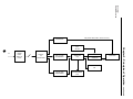
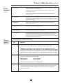
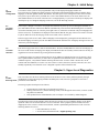
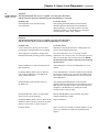
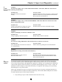
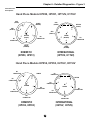
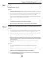
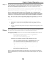
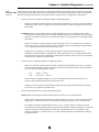
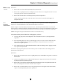
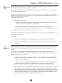
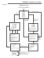
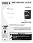
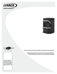
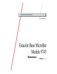
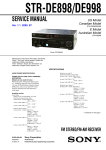
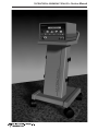
ULTRACISION® HARMONIC SCALPEL® Service Manual
ULTRACISION® HARMONIC SCALPEL® Service Manual
Table of Contents
Chapter 1 - General Description
3
1.1 - The ULTRACISION HARMONIC SCALPEL System
Chapter 2 - Principles of Operation
3
2.1 - Hand Piece
2.2 - Generator and Foot Switch
Chapter 3 - Basic Operation
6
3.1 - Description of Controls, Indicators, and Connections
3.2 - Instrument Preparation and Hand Piece Attachment
3.3 - System Test
Chapter 4 - Initial Setup
9
4.1 - System Configuration
4.2 - Language Selection
4.3 - Line Rate Selection
Chapter 5 - Upper Level Diagnostics
9
5.1 - Trouble Shooting Guide
5.2 - Diagnostic Software
5.3 - Extended Functional Test
Chapter 6 - Detailed Diagnostics
16
6.1 - Test Equipment
6.2 - Hand Piece Assembly
6.3 - Generator and Foot Switch
6.3.1 - Power Entry Module
6.3.2 - AC Fusing and Distribution
6.3.3 - Compressor
6.3.4 - Low Voltage Transformer
6.3.5 - High Voltage Transformer
6.3.6 - Generator PCB
6.3.7 - Keyboard/Interlock PCB
6.3.8 - Microprocessor PCB
6.3.9 - Liquid Crystal Display
6.3.10 - Foot Switch
Chapter 7 - Specifications
7.1 -Generator
7.2 - Hand Piece
7.3 - Foot Switch
7.4 - Power Cord
7.5 - Transport and Storage
7.6 - Mode of Operation
27
ULTRACISION® HARMONIC SCALPEL® Service Manual
Table of Contents - continued
Appendix A - Diagnostic Service Mode - Flow Diagram
Appendix B - Wiring Diagrams and Schematic
115 Volt Wir ing (Model GEN01)
230 Volt Wiring (Models GEN22, GEN32)
115 Volt Routing (Model GEN01)
230 Volt Routing (Models GEN22, GEN32)
Generator PCB Schematic
Generator PCB Component Location
Keyboard/Interlock PCB Schematic
Keyboard/Interlock Component Location
CPU PCB Schematic
CPU PCB Component Location
Type CF, Isolated Applied Part
Dangerous Voltage
Chapter 1 - General Description
The ULTRACISION HARMONIC SCALPEL System is indicated for incising tissue when bleeding control and minimal
1.1
thermal injury are desired. The System’s instruments can be used as an adjunct to or substitute for electrosurgery and
The
ULTRACISION steel scalpels. The System operates in two power modes, variable and full.
System
The ULTRACISION HARMONIC SCALPEL instrument blades vibrate longitudinally at 55 kilohertz. This ultrasonic
vibration at the blade enhances its cutting ability while the vibrating blade edge coagulates bleeders as tissues are
incised. Hemostasis occurs when tissue couples with the blade. This coupling causes collagen molecules within the
tissue to vibrate and become denatured, forming a coagulum.
The cutting power can be adjusted during the incision to increase or decrease coagulation and speed of cutting.
Coagulation of large bleeders can be accomplished by captive coagulation where the side of the blade is used to
compress and tamponade the vessel while a short duration of full power seals it.
Chapter 2 - Principles of Operation
2.1
Hand Piece
The System consists of three major components, a Generator, a Hand Piece, and a Foot Switch. The Generator
produces a 55 kilohertz electric signal which is transmitted via a coaxial cable to the Hand Piece, which then
converts the electrical signal into ultrasonic, mechanical motion. A more detailed explanation follows.
The Hand Piece houses three major components that generate, amplify, and deliver ultrasonic energy to tissues.
When each component is attached to the other and tuned to 55 kilohertz, an acoustic drive train is formed. The
acoustic system or acoustic drive train consists of three components:
•
Acoustic Transducer: converts the electrical energy into motion. The transducer consists of four piezoelectric
elements held in compression between two aluminum end bells. When an AC wave form is applied to the
transducer, the ceramics expand and contract to produce longitudinal motion.
•
Acoustic Mount: attaches the acoustic drive train to the Hand Piece. The mount also provides mechanical
amplification of the longitudinal motion.
•
Instrument Blade: couples the ultrasonic energy to the tissue and amplifies motion. In a laparoscopic
configuration, the blade is elongated by means of a "Laparosonic Extension." This extension allows the
ultrasonic energy to propagate from the Hand Piece to the instrument blade with minimal loss.
The Generator consists of ten modules that drive and cool* the Hand Piece. The Generator converts the AC line
2.2
Generator and voltage to a controlled DC level. The DC level is then remodulated at the resonant frequency of the Hand Piece. The
remodulated signal is then filtered and delivered to the Hand Piece where it resonates the acoustic train. A more
Foot Switch
detailed description follows.
•
Power Entry Filter: accepts a standard, hospital grade utility cord. It provides susceptibility filtering from the
external environment as well as suppressing electromagnetic emissions produced by the Generator that could be
conducted back through the power cord.
•
AC Fusing and Distribution Components: provide line voltage to a cooling compressor, a high voltage
transformer, and a low voltage transformer. Fusing protects these assemblies and others from overload
conditions.
•
Cooling Compressor: provides cooling air via a silicone hose to Hand Piece models HP050, HP051, HPTUV,
and H1TUV.
* Generator provides cooling to models HP050, HP051, HPTUV and H1TUV only.
3
Chapter 2 - Principles of Operation continued
2.2
Generator and
Foot Switch
•
Low Voltage Transformer: produces low voltage AC that is later rectified, filtered, and regulated to produce
+5 VDC, +12 VDC, and -12 VDC. It also provides an important safety barrier. The voltage generated on the
secondary of the transformer is isolated - i.e. the voltage is not referenced to earth ground.
•
High Voltage Transformer: produces high voltage AC (250 VAC) that is later rectified, filtered and regulated
to produce a variable DC level used in driving the Hand Piece. It also provides an important safety barrier. The
voltage generated on the secondary of the transformer is isolated - i.e. the voltage is not referenced to
earth ground.
•
Generator PCB: produces power at ultrasonic frequencies to drive the Hand Piece. This is accomplished
as follows:
continued
-
An SCR switching circuit, filter, and software regulate power rectified from the high voltage transformer
to a predefined level, determined by the user-selected power level. Additionally, a zero crossing detection
circuit informs the software when the AC line voltage swings through zero volts. This allows the software
to schedule SCR firings.
-
The DC voltage is then converted into a 55 kilohertz (+/-2 KHz) square wave by means of a
FET switching circuit.
-
The 55 kilohertz square wave is then filtered by a resonant LC network to produce the sinusoidal wave
form that drives the hand piece.
In addition, the generator PCB contains a phase lock loop circuit that monitors the resonant frequency of
the Hand Piece and adjusts the 55 kilohertz up or down to stay at resonance, which changes with
temperature and load.
A secondary function of the Generator PCB is to provide a central point of connectivity for the other PCBs and
modules in the Generator.
The third function is to rectify, filter, and regulate the low voltage AC to generate the logic voltages. These
voltages are +5 VDC, +12 VDC, and -12 VDC. Logic voltage is also inverted to supply power for the
LCD back light.
•
Keyboard/Interlock PCB: The Keyboard portion of this PCB informs the user of the operative state of the
ULTRACISION HARMONIC SCALPEL System using LED indicators. It also allows the user to change the default
settings as described in Chapter 3 of this manual and in the Generator Manual.
The interlock portion of this assembly acts as a shunt, placing a resistive load across the output to the blade
whenever it is not activated at the VAR or FULL power levels. The interlock is used to quickly stop the blade
motion once the Foot Switch pedal is released.
•
Microprocessor PCB: The microprocessor PCB contains the software program that drives the ULTRACISION
HARMONIC SCALPEL System. The software monitors zero crossings, regulates DC voltage, processes button
and pedal activations, and drives the liquid crystal display. It also monitors performance of the generator PCB
and the acoustic drive train.
•
Liquid Crystal Display: The liquid crystal display reports the operative mode of the ULTRACISION System.
It is driven by the microprocessor PCB via the generator PCB.
•
Foot Switch: The Foot Switch module allows the user to activate the system in either variable or full mode
based on which foot pedal is being pressed. Pedal activations are communicated with the microprocessor via the
keyboard/interlock and generator PCB.
4
Generator
System Overview
AIR (models HP050, HP051, HPTUV & H1TUV)
COMPRESSOR
5
AC
POWER
ENTRY
MODULE/
FILTER
FUSING &
AC
DISTRIBUTION
HIGH VOLTAGE
TRANSFORMER
GENERATOR
PCB
KEYBOARD
HAND PIECE
INTERLOCK
55 KHz
LCD
LOW VOLTAGE
TRANSFORMER
MICROPROCESSOR
PCB
Chapter 2 - Principles of Operation continued
FOOTSWITCH
Chapter 3 - Basic Operation
3.1
Controls,
Indicators, and
Connections
4
3
ULTRACISION
5
GENERATOR
ETHICON ENDO-SURGERY
2
1
SAVE
READY
13
12
11
6
5 4 3 2 1
STANDBY
10
VARIABLE
9
FULL
7
8
Note: This illustration shows Generator Model GEN01. In Model GEN32, the position of the air and electrical connectors is reversed.
Component
Description
1
Power Switch
Controls the electrical power for the entire Generator. Push the switch up to turn power on, push
the switch down to turn power off.
2
Green Power Indicator Light
The light is illuminated when the Generator power is on.
3
20 Character Liquid Crystal
Display
In READY mode, this display indicates the selected variable power level. When the Hand Piece
is energized, this display indicates the active power level. “STANDBY” is displayed
when the Generator is in STANDBY mode.
When the Generator power is first turned on, this display briefly indicates that a SELF TEST is in
progress. This display is also used for alarm messages.
When activated by service personnel, this display also shows diagnostic information, language
selection, and Generator adjustment information.
4
Increase Power Button
Push this button to increase the variable power setting to the desired level, as displayed on the
liquid crystal display, from 1 (minimum power) to 5 (maximum power).
5
Decrease Power Button
Push this button to decrease the variable power setting to the desired level from 5 to 1.
6
Save Button
Push this button to save the currently selected variable power level so that it is automatically
displayed the next time the Generator power is turned on.
7
Volume
Turn this knob to adjust the sound of the Audio Annunciator. The sound level cannot be adjusted
to zero.
8
Display
Turn this knob to obtain the best liquid crystal display appearance for your particular lighting and
viewing angle.
6
Chapter 3 - Basic Operation continued
3.1
Controls,
Indicators, and
Connections
9
Status Lights
Ready Light. This light is illuminated when the system is ready to use. This light is off while the
Hand Piece is energized or in STANDBY mode.
Variable Light. This light is flashed on and off when the Hand Piece is energized at the
variable (VAR) power level.
continued
Full Light. This light is flashed on and off when the Hand Piece is energized at the full
(FULL) power level.
10 Standby Button
This button toggles between STANDBY and READY mode. Push this button once to enter
STANDBY mode. In STANDBY mode, all power is removed from the Hand Piece. The Increase,
Decrease, and Save buttons are disabled as is the Foot Switch. Use the STANDBY mode when
replacing instrument blades.
11 Release Button
Push this button to detach the Hand Piece cord connection from the Cooling Air Source
Connector on the Generator.
12 Cooling Air Source
Refer to the appropriate Hand Piece package insert.
13 Electrical Receptacle
Delivers the energy from the Generator to the Hand Piece.
*
3.2
Instrument
Preparation and
Hand Piece
Attachment
Audio Annunciator
The annunciator beeps to indicate instrument activity or to indicate error conditions. During
normal activation, the annunciator beeps on and off when either foot pedal is pressed. A slower
beep indicates that LEVEL 1 through LEVEL 4 is activated and a faster beep indicates that
LEVEL 5 is activated. If the generator does not energize the instrument, the annunciator will emit
a continuous beep when either pedal is pressed.
Instrument Preparation and Hand Piece Attachment
Step
1
Instruction
Ensure that the Generator Power Switch is off during instrument preparation.
WARNING: To avoid injury, the activatedULTRACISION HARMONIC SCALPEL
instrument should not be in contact with drapes or other flammable materials. During
prolonged activation, the instrument blades may become hot. Avoid unintended blade
contact with tissue, drapes, surgical gowns, or other unintended sites after activation.
2
Plug the line cord into a grounded receptacle:
Model GEN01:
Model GEN32:
115 Vac, 60 Hz
230 Vac, 50 Hz
Note: Do Not Connect the Generator To An Ungrounded Outlet.
3
Connect the Foot Switch to the rear panel of the Generator. Align the red dot on the Foot
Switch 4-pin connector with the red dot 4-pin connector on the lower left side of the
Generator back panel.
7
Chapter 3 - Basic Operation continued
3.2
Instrument
Preparation and
Hand Piece
Attachment
4
Attach the sterile ULTRACISION® HARMONIC SCALPEL® Hand Piece following the
appropriate package insert instructions:
Note: Refer to specific instrument package inserts for use of the Generator during surgical cases.
continued
3.3
System Test
5
Attach an instrument blade to the Hand Piece following the instructions listed in the
instrument’s package insert.
6
Turn Generator power on.
7
If the Hand Piece has been steam sterilized (autoclave or flash), wait 5 minutes with the
Hand Piece attached to the Generator and the Generator on to allow the Hand Piece to dry.
STANDBY Mode is recommended during this period of time.
8
If the Generator is in STANDBY Mode, press the Standby Button to return it to READY
Mode. If the generator is not already at power level 5, select level 5 by using the Increase
Button.
The ULTRACISION HARMONIC SCALPEL System is now ready for testing. After performing the very basic
tests which follow, the more detailed functional tests described in section 5.3 are recommended.
Caution: During this testing, the instrument blade will become active. Do not touch the blade!
Step
Instruction
1
Energize the blade by pressing a pedal on the Foot Switch.
2
Apply the blade to wood, cardboard, or wax and verify the blade burns and cuts. If the
system fails this basic functional verification, refer to the upper level diagnostic section of
this manual (Chapter 5).
8
Chapter 4 - Initial Setup
4.1
System
Configuration
Two features of the system are user programmable. They are the displayed language and line rate.
The system may be configured to display messages in languages other than the default setting of English. These
languages are French, Spanish, Italian, and German. Also, the system can be configured to run at 50 or 60 Hertz.
The system is preset at the factory such that all 115 VAC units (Model GEN01) are at 60 Hz, and all 230 VAC
units (Model GEN32) are at 50 Hz. If the line rate is set inappropriately, a system error will always be displayed at
normal power up. To change the language or line rate, refer to the following sections.
4.2
Language
Selection
Follow steps 1 through 5 in section 3.2 to prepare the Generator for power up. Prior to turning the Generator on,
press and hold the Increase and Decrease Buttons simultaneously with one hand. While holding these two buttons
in, turn the Generator power on. Once the power light comes on, release the two buttons. The preset language and
software revision (1.35) should now be displayed. This indicates that the first page of the service mode is accessed.
If you are unable to access this first page of the service mode, refer to section 5.2.
In the first page of the service mode, different languages can be displayed by pressing the Increase Button. Once
the desired language is located, press the Save Button and turn the Generator off. All display messages will now be
in the newly selected language.
4.3
Line Rate
Selection
Enter the first page of the service mode as described above. Press the Standby Button to access the second page of
the service mode. In this second page, the display will indicate the line rate currently selected. The line rate may be
toggled between 50 Hz and 60 Hz by pressing the Increase Button.
A validation sequence is required to change the line rate. In addition to updating the line rate, the memory check
sum is updated and the error history is erased. This is explained in more detail in section 5.2. Before entering the
validation sequence, verify that the number following the letters CRC is 55947. If this is not the case, do not
continue with the validation (see section 5.2). Once 55947 is verified, enter Save, Increase, Decrease, Save, and
Standby sequentially. The Generator is now configured to operate at the selected line rate
Chapter 5 - Upper Level Diagnostics
5.1
Trouble
Shooting Guide
This section discusses the most common problem areas and how to resolve these problems primarily through
modifications to usage and swapping of blades and hand pieces. This section is a good place to start once a
problem has been identified.
The testing sequence should proceed as follows:
1.
2.
3.
Perform the basic functional test as described in section 3.3.
Starting with section 5.1 (Trouble Shooting Guide), work through the sub-sections (5.2 and 5.3) until
the problem is identified.
If the problem then is still unidentified, refer to Chapter 6 for a module by module diagnosis.
The following section lists the probable causes and corrective actions for error conditions that may occur during
operation of the ULTRACISION HARMONIC SCALPEL Generator. If the symptoms specified in this section are
inappropriate or the corrective actions are insufficient, consult a qualified hospital technician or call one of the
following numbers for service:
• 1-800-USE-ENDO (U.S. calls)
• 1-513-483-8901 (International calls - English speaking only)
9
Chapter 5 - Upper Level Diagnostics continued
5.1
Trouble Shooting
Guide, continued
Symptom:
The instrument blade fails to cut or coagulate or has less power than usual,
and the Generator emits intermittent beeps when the Hand Piece is activated.
Probable cause
Instrument blade is not attached securely
to the Hand Piece.
Corrective Action
After pushing the Standby Button on the Generator,
manually tighten the instrument onto the Hand Piece
(finger tight only). Use the blade wrench to secure the
instrument completely to the Hand Piece by turning the
wrench clockwise until a “snap” is heard.
Symptom:
The instrument blade fails to cut or coagulate or has less power than usual,
and the Generator emits a steady tone when the Hand Piece is activated.
Probable cause
Contact with tissue or fluid is excessive and is
preventing the instrument blade from resonating.
Corrective Action
Withdraw the instrument from tissue or fluid and use less
pressure when pushing against tissue.
Tissue fragment or coagulum is clinging to the
instrument blade and preventing it from resonating.
Activate the Hand Piece for 1 or 2 seconds with the
instrument in air to remove tissue, etc. If this fails, allow the
blade to cool and then wipe it with a sterile cloth. Handle
the instrument with caution as it may become hot during
operation in air.
Inside of Hand Piece is still warm from steam or
flash sterilization.
Allow Hand Piece to cool at room temperature for 15-30
minutes.
For Models HP050, HP051, H1TUV, HPTUV
only: Inside of Hand Piece is still damp from
steam or flash sterilization.
Leave both Hand Piece connectors attached to the Generator
and leave the Generator power on and in STANDBY mode
for 5 minutes to allow the Hand Piece air flow to cool and
dry the Hand Piece.
Instrument blade is not attached securely to
the Hand Piece.
After pushing the Standby Button on the Generator,
manually tighten the instrument onto the Hand Piece (finger
tight only). Use the blade wrench to secure the instrument
completely to the Hand Piece by turning the wrench
clockwise until a “snap” is heard.
Instrument blade has visible or invisible defect
which prevents it from resonating.
Push the Standby Button on the Generator and replace
instrument blade and/or sheath.
For Models HP050, HP051, H1TUV, HPTUV only: Replace Hand Piece.
Hand Piece failure caused by immersion in liquid,
damage to power cable, or end of useful life.
Generator failure.
Refer to section 6 for a module by module diagnosis or call
for service. (Numbers are listed at the beginning of this
chapter)
10
Chapter 5 - Upper Level Diagnostics continued
5.1
Symptom:
Trouble Shooting The Generator will not enter READY mode from STANDBY mode.
Guide, continued
Probable cause
Foot Switch pedal is depressed while
pushing Standby Button.
Corrective Action
Release all pedals and switches while entering
READY mode.
Symptom:
The Generator beeps and/or changes mode unexpectedly.
Probable cause
The Generator is located too close to an
electrosurgical generator.
Corrective Action
Locate the Generator at least one foot away from
electrosurgical generators.
Hand Piece is defective.
Replace the Hand Piece.
Foot Switch is defective.
Replace the Foot Switch. Refer to Chapter 6 or call for
service. (Numbers are listed at the beginning of this section)
Electrical interference from hospital wall power
or other equipment in O.R. disturbs Generator.
Refer to Chapter 6 or call for service.
Symptom:
End of instrument blade detaches, leaving the blade extension in the Hand Piece.
Blade was attached to the Hand Piece with
excessive force.
Push Standby Button. Remove and discard the blade extender
from the Hand Piece. Attach a new instrument blade to the
Hand Piece.
Material between the blade and the Hand Piece
has jammed the connection.
Push Standby Button. Remove and discard the blade base
from the Hand Piece. Clean the end of the blade mount
surface on the Hand Piece with alcohol and sterile gauze. Do
not immerse the Hand Piece in liquid.
Symptom:
READY light is not illuminated.
Probable cause
Generator is in STANDBY mode.
Corrective Action
Push the Standby Button to enter READY mode.
Foot Switch is depressed while the
Generator is turned “on” and goes
through self-test.
Release the Foot Switch until the Generator self-test
is completed and the READY light comes on.
Hand Piece is defective.
Replace the Hand Piece.
Generator is defective.
Turn Generator power off. Refer to Section 6 for a module by
module diagnosis or call for service.
11
Chapter 5 - Upper Level Diagnostics continued
5.1
Symptom:
Trouble
The Generator display reads, “STOP! CHECK HAND PIECE - TURN OFF, THEN ON” and Generator
Shooting Guide, emits long and short beeps.
continued
Probable cause
Hand Piece connection to Generator
is faulty.
Corrective Action
Turn Generator Power Switch off, check to see that electrical
Hand Piece connector is securely attached to the Generator,
then turn the Power Switch back on.
Symptom:
The Generator display reads, “STOP! SYSTEM ERROR - TURN OFF, THEN ON” and Generator emits
bursts of long and short beeps.
Probable cause
Problem with hospital line voltage power source
disturbed Generator or the Generator is faulty.
Corrective Action
Turn Generator Power Switch off and then on again.
Symptom:
Liquid crystal display on Generator is difficult to read.
Probable cause
Change in lighting or Generator position.
Corrective Action
Readjust display control on Generator.
Symptom:
Air connector or Plug on Hand Piece cable will not fit into air connector on Generator.
Probable cause
Silver locking button on Generator air connector
is in locked position.
Corrective Action
Unlock connector by pushing the silver Release Button.
Symptom:
High-pitched screeching sound emitted from Hand Piece
Probable cause
Instrument blade is not fully seated on
Hand Piece blade mount.
5.2
Diagnostic
Software
Corrective Action
Re-tourque the instrument blade with an alternate torque
blade wrench and/or clean the threaded Hand Piece blade
mount with an alcohol 4x4.
The Generator contains a built-in diagnostic mode accessible to service personnel. If a problem exists with the
system and resolution cannot be obtained through the Trouble Shooting Guide (section 5.1), enter the diagnostic
service mode as described below and diagrammed in Appendix A. Typically, once a problem has been identified, it
requires further diagnosis inside the Generator. To perform this detailed diagnosis, refer to section 6. NOTE: It is
important to read all of Chapter 6, which details disassembly, test equipment, and warnings, prior to performing
detailed diagnosis of any internal module.
Follow steps 1 through 5 in section 3.2 to prepare the Generator for power up. Prior to turning the Generator on,
press and hold the Increase and Decrease buttons simultaneously with one hand. While holding these two buttons
in, turn the Generator power on and verify the following:
1.
Verify that the green power LED is illuminated. Proceed to the next step.
12
Chapter 5 - Upper Level Diagnostics continued
5.2
Diagnostic
Software,
The green power LED located on the keyboard PCB is driven from the +5 VDC supply on the generator
PCB. The most likely mode of failure is no AC voltage leading to the Generator PCB. If no other generator
activity is noticeable (i.e. air compressor noise, other LEDs, or displayed information), check the wall
outlet and the first two modules of the primary AC circuit as described in Chapter 6. If other generator
activity is noticed, verify that low voltage AC is reaching the generator card (see section 6.3.4) and that the
generator PCB is producing +5 VDC (see section 6.3.6).
continued
2.
For generators utilizing Hand Piece Models HP050, HP051, HPTUV, and H1TUV, verify that the
compressor is running by checking for vibrational noise from within the Generator and the release of
cooling air. Proceed to the next step.
The most likely mode of compressor failure is no AC voltage at the compressor. Verify that AC voltage is
being distributed from the fuses to the compressor (see Chapter 6).
For Hand Piece Models HP050, HP051, HPTUV, and H1TUV: If the compressor is vibrating but no
cooling air is being exhausted from the Hand Piece, check the air line in the Generator, the air inlet filter
(located on the side of the compressor), and the Hand Piece for blockage or rupture.
3.
Verify that the first page of the service mode is accessed. This is indicated by the display reading the
preset language followed by software revision 1.35. Proceed to the next step.
Several modes of failure could exist at this point, as follows:
•
SYSTEM ERROR is displayed:
This condition would most likely exist if the generator PCB is unable to regulate the DC voltage used
in driving the hand piece. This can be caused by either a faulty generator or microprocessor PCB.
Refer to section 6.3.6 to replace the generator PCB and re-test. If re-testing fails, refer to section 6.3.8
to replace the microprocessor PCB.
•
CRC "Five digit number" followed by the line rate is displayed:
This indicates that the second page of the service mode has been accessed. When the software detects
a memory error during self test and the service mode is initiated, the software jumps to the second
page of the service mode. If the number following the CRC is 55947 and the line rate is appropriate
(see section 4.3 to change the line rate), enter the following software validation sequence. Press
sequentially Save, Increase, Decrease, Save, Standby. If this problem persists and 55947 is not the
number following CRC, replace the microprocessor PCB (see section 6.3.8).
•
LEVEL # (typical message during normal power up) is displayed:
This will typically happen when the Increase and Decrease buttons were not held in during
power up. Turn the Generator off and re-attempt to access the service mode. This will also occur if
the Foot Switch is activated during power up. If the problem still exists, it usually indicates that the
keyboard PCB is faulty. Check all the cabling leading from and to the keyboard. If it appears intact,
replace the keyboard PCB (see section 6.3.7).
A less likely cause is a faulty generator or microprocessor PCB. If the problem persists, try
sequentially replacing these PCBs (see sections 6.3.6 and 6.3.8).
•
Blank display:
Typically, when the display appears blank, the problem can be fixed by turning the viewing angle
adjustment pot on the front of the generator. If this fails to solve the problem, the cabling leading to the
display (and adjustment pot) or the microprocessor PCB is faulty. Verify that the cabling is intact and,
if the problem persists, replace the microprocessor and re-test (see sections 6.3.8 and 6.3.9). If there is
information on the display but it appears in a foreign language, press the Increase Button to review the
available languages. Once the desired language is located, press Save to select it (see section 4.2).
13
Chapter 5 - Upper Level Diagnostics continued
5.2
Diagnostic
Software,
•
continued
4.
Random characters:
Random or nonsense characters usually indicate a faulty microprocessor PCB.
Replace the microprocessor and re-test (see section 6.3.8).
In both cases above, if the display still does not work properly, refer to section 6.3.9 and replace it.
Press the Standby Button and advance to the second page of the service mode. Verify that CRC 55947 and
the proper line rate are displayed. Proceed to the next step.
If 55947 is not displayed, cycle the Generator power and re-attempt this test. If the problem persists,
replace the microprocessor PCB (see section 6.3.8).
If the line rate is inappropriate, refer to section 4.3 to change it.
5.
Press the Standby Button and advance to the third page of the service mode. In this page,
the relative current, voltage, frequency, selected power level, and mode are displayed. Verify
that these values are within the normal operating parameters. Proceed to the next step.
From left to right, the display should indicate the following normal operating parameters:
Relative current
Between 40 and 50 (mA)
Relative DC voltage
Between 15 and 25 (v)
Output frequency
Between 50,000 Hz and 60,000 Hz
Selected Power level
Between 1 and 5
Operating Mode
6 (Refer to the value in the lower left hand
corner of the function boxes in Appendix A)
Possible Problems:
• Display voltage or current is low (< 15 or < 40 respectively):
The high voltage AC is not reaching the generator PCB or the generator PCB's switching power
supply is not working. Verify that the high voltage AC is at the generator PCB (see section 6.3.5). If
no AC is present, check the high voltage wiring, transformer, and fusing (see sections 6.3.5 and 6.3.2).
If AC is present, replace the generator PCB (see section 6.3.6).
•
Display voltage or current is high (> 25 or > 50 respectively):
The power regulation circuit on the generator PCB is not functioning properly.
See section 6.3.6 and replace the PCB.
•
Display frequency is high or low (> 60,000 or < 50,000):
The frequency control circuit on the generator PCB is not functioning properly.
See section 6.3.6 and replace the PCB.
6.
Verify that the READY LED is now illuminated. Proceed to the next step.
If the READY LED does not come on, either the LED itself or the interlock circuitry on the keyboard PCB
is faulty. In either case, replace the keyboard and re-test (see section 6.3.7).
7.
Verify that pushing either pedal on the Foot Switch causes the READY LED to go out.
If the READY LED does not go out while pressing either foot pedal, inspect the cabling leading from the
keyboard to the Foot Switch connector on the back of the Generator (see section 6.3.7). If the cabling
appears intact, replace the Foot Switch cable and re-test (see section 6.3.10). If the problem persists,
replace the keyboard PCB (see section 6.3.7).
14
Chapter 5 - Upper Level Diagnostics continued
5.2
Diagnostic
Software,
8.
Return to the second page of the service mode and review the error history list as follows:
Turn the Generator off. Access page one of the service mode by holding in the Increase and Decrease
buttons at power up. Press the Standby Button to access page two. CRC 55947 should now be displayed
followed by the line rate and error history.
continued
The numbers in the far right of the display, separated by a "/", indicate the number and type of errors. Press the
Decrease Button to scroll through the last ten errors. An explanation of the error types follows:
Error No.
1-6
Description
Not used and should never appear.
7
The check sum stored in memory does not agree with the calculated value.
This would be caused by an unreliable microprocessor PCB. See section
6.3.8 to replace the microprocessor.
8
The frequency control circuit on the generator PCB is not oscillating. See section 6.3.2
to check for a blown fuse. If all the fuses are intact, see section 6.3.6 to replace the
generator PCB.
9
A higher than normal voltage was detected on the output of the switching power supply
circuitry located on the generator PCB. This may be caused by either electrical interference
from other devices in the O.R. or by a faulty generator PCB. Verify that the Generator is not
within one foot of any other equipment (especially electrosurgical devices). If the problem
persists, replace the generator PCB (see section 6.3.6).
10
The cabling leading from the generator PCB to the keyboard became disconnected or
is intermittent.
11
The microprocessor PCB is unable to match the selected line rate with the actual frequency
of the line voltage. Verify that the Generator is configured for the appropriate line rate (see
section 4.3). If the problem persists, there is typically significant noise on the AC source.
NOTE: Whenever error numbers 7, 8, 9, or 11 are added to the error history, a SYSTEM ERROR
is displayed.
NOTE: The error history is erased whenever the validation sequence is entered from this second page of
the service mode. The validation sequence is described in section 4.3.
If a problem with the ULTRACISION System is still unidentified after performing the steps listed above, continue
5.3
Extended
the diagnosis with the Extended Functional Test.
Functional Test
If a problem exists with the system and resolution cannot be obtained through the Trouble Shooting Guide (section
5.1) and the Diagnostic Service Mode (section 5.2), proceed with the following steps to be performed at power up.
Again, it is important to read all of Chapter 6, which details disassembly, test equipment, and warnings, prior to
performing detailed diagnosis of any internal module.
CAUTION: During this testing, the instrument blade will become active. Do not touch the blade!
1.
Turn the Generator on as described in steps 1 through 8 in section 3.2.
2.
If not already at Level 1, press the Decrease Button until LEVEL 1 is displayed.
15
Chapter 5 - Upper Level Diagnostics continued
5.3
Extended
Functional Test,
3.
continued
Activate the instrument blade by pressing the foot switch pedal labeled VAR. Verify that the VAR LED
flashes and that the Generator Audio Annunciator beeps. Activate the instrument blade by pressing the
foot switch pedal labeled FULL. Verify that the FULL LED flashes and that the annunciator beeps.
If the LED does not light, the keyboard PCB is faulty. See section 6.3.7 and replace the keyboard.
If the annunciator does not beep, check the cabling leading from the generator PCB to the volume
control pot on the front panel. Also, check the cabling leading from the annunciator to the keyboard.
If the cabling appears intact, either the drive circuitry in the generator PCB or the keyboard PCB is faulty.
Sequentially replace these boards and re-test (see section 6.3.6 and 6.3.7).
If the problem persists, replace the annunciator.
If the LED and annunciator stay on continuously, the Generator is unable to resonate the blade. Since the
previous sections of this manual have already identified the typical causes of this failure (blade failure,
blade attachment torque, Hand Piece failure, broken cabling inside the generator) it is most likely that
the LC filter network in the generator PCB is faulty. See section 6.3.6 and replace the generator PCB.
4.
Activate the instrument blade by pressing the FULL pedal. Press the blade into wood, cardboard, or wax
and observe that the blade cuts. While holding the FULL pedal down, increase the pressure on the blade
until the blade is no longer able to resonate. This is indicated by a continuous tone and LED illumination.
While still holding the pedal down, remove the blade from the cutting material and verify that the blade
again starts to resonate. This is indicated by the normal LED flashing and a non-continuous tone. This
regaining of resonance is referred to as "lock recovery."
NOTE: A warm Hand Piece/instrument blade may not regain resonance. If this test fails, allow the Hand Piece
to cool for several minutes and cool the blade tip with water.
Since the previous sections of this manual have already identified the typical causes of failure to cut or
lock recover, it is most likely that the phase lock loop circuitry in the generator PCB is faulty. See section
6.3.6 and replace the generator PCB.
If a problem with the system is still unidentified after performing these four steps, proceed to the Detailed
Diagnosis section (Chapter 6) of the manual and test each module for the expected input and output.
Chapter 6 - Detailed Diagnostics
This section of the manual specifies the expected input and output of each module of the ULTRACISION System.
Previous sections of this manual will direct the service person to a specific module (sub-section) within this section.
Each sub-section specifies the testing procedure - including assembly/disassembly - and test equipment.
NOTE:
Directions such as left and right assume that the reader is facing the
operator's panel.
Warning:
High voltages and currents are used in the generator. Take electric
shock precautions.
Warning:
Ultrasonic energy can cause severe burns. Handle acoustic components
with care.
Caution:
Damage may be done to the generator if power is lost to the microprocessor PCB.
Whenever microprocessor PCB performance is in doubt, the high voltage power supply
should be disabled; refer to section 6.3.6 for instructions.
16
Chapter 6 - Detailed Diagnostics continued
6.1
Test
Equipment
The following is a list of the equipment required in order to perform this level of testing:
1.
A digital voltmeter (FLUKE model 45 or equivalent) with insulated test probes
and clips.
2.
A dual channel oscilloscope with x10 probes.
3.
An autotransformer adjusted for nominal line voltage (115 or 230 volts).
4.
A means of "floating" the generator ground - i.e. breaking the safety ground
connection at the line cord.
NOTE: For all the following tests, it is helpful to refer to the appropriate wiring diagram
(115 VAC or 230 VAC) located in Appendix B.
6.2
Hand Piece
Assembly
The majority of problems with hand pieces are covered in section 5.1, the Trouble Shooting Guide. The Hand Piece
itself is a permanently assembled device with no internal components that are serviceable. The Hand Piece has a
limited life and will eventually "wear out."
Because the sub-assemblies of the Hand Piece are inaccessible, this test verifies some aspects of continuity. This
test will partially determine if the Hand Piece has an open wire only but will not check all wires and will not
determine if the Hand Piece is worn out.
Hand Piece Models HP050, HP051, HPTUV, H1TUV
With the Hand Piece unplugged from the Generator:
Verify continuity between pins 4, 6, and 7 in the Hand Piece electrical connector.
For Models HP050 and HP051, verify continuity between pin 1 and the tip of the blade (see Figure 3 for pin
location.
For Models HPTUV and H1TUV, verify continuity betwen pin 2 and the tip of the blade (see Figure 3 for pin
location.
If an open wire is detected in a domestic hand piece (models HP050, HP051), un-screw the back of the electrical
connector and check for any broken wires. If breaks are noticeable, repair the connector in accordance with Figure
3. If no breaks are noticed or an international hand piece is being tested (permanently assembled connector), no
further testing can be performed. Replace the hand piece.
Hand Piece Models HP052, HP053, H2TUV, H3TUV
With the Hand Piece unplugged from the Generator:
For Models HP052 and HP053, verify continuity between pin 1 and the tip of the blade (see Figure 3 for pin
location.
For Models H2TUV and H3TUV, verify continuity betwen pin 2 and the tip of the blade (see Figure 3 for pin
location.
There is no method for repairing these hand pieces. If defective, these hand pieces must be replaced.
6.3
Generator and
Foot Switch
Access to the internal generator modules requires disassembly of the Generator. Remove the power cord and the six
phillips head machine screws from the bottom of the Generator enclosure and remove the top portion of the
enclosure shell.
The internal generator modules are now exposed. Additional disassembly may be necessary depending upon the
level of testing required.
Verify that the Hand Piece, Foot Switch, and instrument blade are appropriately attached to the Generator.
Proceed through the following sections until the problem module is identified.
17
Chapter 6 - Detailed Diagnostics - Figure 3
Hand Piece Pin
Descriptions
Hand Piece Models HP050, HP051, HPTUV, H1TUV
GRD
(DRAIN)
GRD
(DRAIN)
POWER
(BROWN)
7
2
GRD
(DRAIN 2)
RETURN
(BLACK)
7
2
6
GRD
(DRAIN 2)
1
5
3
RETURN
(BLACK)
NO
CONNECTION
4
6
NO
CONNECTION
1
5
POWER
(BROWN)
3
NO
CONNECTION
4
SENSE
(ORANGE)
SENSE
(ORANGE)
DOMESTIC
(HP050, HP051)
INTERNATIONAL
(HPTUV, H1TUV)
Hand Piece Models HP052, HP053, H2TUV, H3TUV
NO
CONNECTION
NO
CONNECTION
NO
CONNECTION
POWER
7
7
2
2
6
NO
CONNECTION
1
RETURN
5
NO
CONNECTION
RETURN
3
4
6
POWER
NO
CONNECTION
3
5
NO
CONNECTION
NO
CONNECTION
1
4
NO
CONNECTION
INTERNATIONAL
(H2TUV, H3TUV)
DOMESTIC
(HP052, HP053)
18
NO
CONNECTION
Chapter 6 - Detailed Diagnostics continued
6.3.1
Power Entry
Module
Warning: The output terminals of this device are live whenever the line cord is plugged into the Generator and into
a live outlet.
The power entry module is located on the left side of the back panel and wired with quick disconnect terminals. For
a functional description see section 2.2.
Verification:
1.
Input power is supplied via the IEC appliance connector on the line cord. If not already so, insert the cord
fully into the back of this module.
2.
The output terminals (black and white wires) should carry the appropriate line voltage regardless of the
position of the front panel power switch. Plug the cord into an outlet and verify this voltage.
3.
In 115 VAC generators (Model GEN01) the entry module contains an external fuse drawer. Check these
fuses (see section 6.3.2) before deciding to replace this module.
Replacement:
1.
Disconnect the line cord, remove the two terminals, de-solder the green grounding wire, and un-screw the
two machine screws securing the power entry module to the back panel.
2.
Remove the power entry module and replace it with the appropriate part listed in Appendix C.
This module is located directly underneath the power entry module in 115 VAC generators (Model GEN01) and on
6.3.2
AC Fusing and the far right in 230 VAC generators (Models GEN22 and GEN32). For a functional description see section 2.2.
Distribution
Verification:
1.
All fuses used in the generator are time delayed and therefore may appear closed when they are actually
open. Remove the power cord and test each fuse with an ohm meter to ensure they are closed.
2.
In the 115 VAC generators, test the three fuses in the fuse block via the access holes. Also test the two
fuses located in the fuse drawer in the lower portion of the power entry module.
3.
In the 230 VAC generators, test the six fuses in the fuse block via the access holes.
4.
Refer to the wiring diagram in Appendix B and verify that the primary wiring is intact by re-inserting the
power cord, switching the generator on, and testing for the appropriate line voltages via the access holes in
the top of the fuse block.
5.
If no voltage is detected and all the fusing and wiring is intact, replace the power switch on the
front panel.
Replacement:
1.
For all replacements, disconnect the line cord and refer to Appendix C for the replacement
part number.
2.
To replace fuses, lift the applicable hinged section of the fuse block and remove the fuse.
3.
To replace an individual fuse housing or terminal block, unscrew the two stops at the ends of the fuse rail.
Slide the fuse housing or terminal block off the rail and remove the attached wires.
4.
To replace the front panel power switch, remove the four terminals, squeeze the retaining tabs on the
switch and push it out through the front panel.
19
Chapter 6 - Detailed Diagnostics continued
6.3.3
Compressor
The compressor is screwed to the base plate on rubber feet in the back portion of the Generator. It runs on line
voltage supplied through the fusing and distribution module. When the front panel switch is turned on, the cooling
fins on the compressor quickly become hot and the compressor vibrates; this is normal and is not cause for
replacement. For a functional description see section 2.2.
With power on, remove the Hand Piece air connector. A steady flow of air should be detectable. If available, a
pressure gauge can be used to measure the air pressure, which should be greater than or equal to 4.5 pounds per
square inch. Reconnect the hand piece air connection or plug.
If power is available to the compressor and there is no or reduced air flow, check the hose leading from the
compressor for any perforations or restrictions. Also check the plastic filter housing and filter, located on the side
of the compressor, for any blockage before replacing the compressor (models HP050, HP051, H1TUV, HPTUV).
NOTE: The compressor filter, located in the plastic housing, should be removed and cleaned at least once every
two years. To remove the filter, unscrew the wing nut securing the plastic housing to the compressor.
Replacement:
6.3.4
Low Voltage
Transformer
1.
Disconnect the line cord and unscrew the four phillips head machine screws from the base plate.
2.
Disconnect the two primary wires from the fusing module and remove the grounding wire from the
base plate.
3.
With pliers, unscrew the hose fitting. Remove the compressor and replace with the appropriate part listed
in Appendix C.
The low voltage transformer is screwed to the left side of the base plate underneath the generator PCB and receives
line voltage from the fusing and distribution module. For a functional description see section 2.2.
The output of this transformer terminates at J1 on the generator PCB. Proceed through the following steps to test
for the proper output voltage:
1.
Remove the power cord. Remove the plug at J1 and clip the digital voltmeter to
locations 3 (white wire) and 4 (green wire).
NOTE: Location 1 is next to the filled keying location.
Warning: Stay clear of locations 7 and 8; they are high voltage (250 to 260 VAC).
2.
Supply power and turn the front panel switch on. With nominal line voltage, the open
circuit voltage between locations 3 and 4 should be between 33 and 35 volts AC.
3.
Repeat this process and verify the voltage between locations 2 (yellow wire) and
4 (green wire) is between 16 and 17 volts AC.
4.
Repeat this process and verify the voltage between locations 5 (red wire) and
6 (black wire) is between 9.5 and 10.5 volts AC.
5.
Remove the power cord and replace the J1 plug.
If power is available to the transformer and there is no output voltage, remove the line cord, refer to the wiring
diagram (Appendix B), and inspect the wiring leading to the transformer. If the wiring appears intact, replace the
transformer.
20
Chapter 6 - Detailed Diagnostics continued
6.3.4
Low Voltage
Transformer
continued
6.3.5
High Voltage
Transformer
Replacement:
1.
Remove the line cord, the microprocessor PCB (see section 6.3.8), and the generator PCB
(see section 6.3.6).
2.
De-solder the primary and secondary connections and remove the two phillips head screws securing the
transformer to the base plate. Remove the transformer and replace it with the appropriate part listed in
Appendix C.
The high voltage transformer is bolted to the base plate underneath the generator PCB to the right of the low
voltage transformer and receives line voltage from the fusing distribution module. For a functional description
see section 2.2
The output of this transformer also terminates at J1 on the generator PCB. Proceed through the following steps to
test for the proper output voltage:
1.
Remove the power cord. Remove the plug at J1 and clip the digital voltmeter to locations 7 (blue
wire) and 8 (brown wire). Note: Location 1 is next to the filled keying location.
Warning: Take the appropriate precautions; locations 7 and 8 are high voltage (250 to 260 VAC).
2.
Supply power and turn the front panel switch on. With nominal line voltage, the open circuit
voltage between locations 7 and 8 should be between 250 and 260 volts AC.
3.
Remove the power cord and replace the J1 plug.
If power is available to the transformer and there is no output voltage, remove the line cord, refer to the wiring
diagram (Appendix B), and inspect the wiring leading to the transformer. If the wiring appears intact, replace the
transformer.
Replacement:
6.3.6
Generator
PCB
1.
Remove the line cord, the microprocessor PCB (See section 6.3.8), and the generator PCB
(see section 6.3.6).
2.
De-solder the primary and secondary connections and remove the four nuts/washers securing the
transformer to the base plate.
3.
Remove the transformer and replace it with the appropriate part listed in Appendix C.
The generator PCB is supported on an aluminum bracket above the high and low voltage transformers, and under
the microprocessor PCB. The generator PCB serves as a central point of connectivity and receives inputs from all
other PCBs and transformers. For a functional description see section 2.2.
The simplest way to determine if the generator PCB is working is by substitution. However, the following tests can
be performed if preferred.
In order to access the generator PCB's test points, the microprocessor PCB must be re-oriented in the service
position. With the line cord removed, remove the four screws securing the microprocessor PCB and use two of the
screws to re-attach the board in the inverted position as shown in figure 4.
The following steps will test the four major functional areas of the generator PCB. During these tests, refer to the
generator PCB schematic, found in Appendix B, for a more in depth understanding.
21
Chapter 6 - Detailed Diagnostics continued
6.3.6
All the tests below are made in reference to circuit ground, which is found at TP4, TP10, and TP15. This common
Generator PCB, circuit ground is NOT earth ground, and is not intended to be connected to earth ground. It is therefore important to
continued
break the earth ground connection to the generator before connecting any test equipment to circuit ground.
1.
Verify the processor controlled switching DC supply is regulating properly:
•
With power removed from the generator, clip the leads of the DVM (set for VDC) to TP6, and common
ground (TP4, TP10, or TP15). Apply power, switch the generator on, and verify that TP6 is between 15
and 25 VDC.
WARNING: Higher voltages indicate improper supply regulations; remove power quickly if the voltage
exceeds 100 VDC. Even after power is removed, hazardous charge may be retained on the power supply
capacitors. If continued testing is desired, disable this supply by removing the fuse(s) to the high voltage
transformer.
2.
•
With power removed from the generator, clip the oscilloscope (set for a 5 volt pulse at 60 to 50 Hz) to
TP16. Apply power, switch the generator on, and verify that a positive fixed width pulse approximately
1 msec wide and synchronized to the line frequency exists.
•
If higher or lower voltages are noticed, either this portion of the generator PCB is bad or the
microprocessor PCB is unable to regulate the DC voltage. If this is the case, re-test the generator PCB
with a substitute microprocessor PCB before replacing this PCB. If the pulse at TP16 is not synchronous
with the line rate, replace the generator PCB.
Verify that the low voltage DC supplies are regulating properly:
•
With power removed from the generator, clip the common lead of the DVM (set for VDC) to common
circuit ground. Sequentially, clip the other lead to each of the test points listed below, turn the generator
power on, and verify the appropriate voltages:
TP1:
TP2:
+5 VDC +/- 20 mV
+12.65 VDC +/- 250 mV
NOTE: TP2 may be slightly difficult to access. Even with the microprocessor PCB in the service
position, TP2 is still located under the microprocessor PCB.
•
3.
If higher or lower voltages are noticed and the output of the low voltage transformer has been verified
(see section 6.3.4), replace the generator PCB.
Verify that the ultrasonic drive circuit is functioning properly:
Caution: During this testing the instrument blade will become active. Do not touch the blade.
•
With the power removed from the Generator, clip the oscilloscope (set for 2 volts at 55,000 Hz) to TP11.
Apply power, switch the generator on, and energize the hand piece at full power for several seconds.
•
The voltage wave form at TP10 should be between 1V to 1.22 peak to peak at a frequency between
54,000 Hz to 55,500 Hz and approximately sinusoidal. This spread in voltage and frequency is caused by
variations in the type of blade attached to the hand piece and the hand piece itself. Therefore, if the
voltage or frequency is not within range, re-test with a different hand piece and blade before replacing
the generator PCB.
22
Chapter 6 - Detailed Diagnostics continued
6.3.6
Replacement:
Generator PCB,
continued
1.
Remove the line cord and all cabling leading to the generator PCB.
2.
Remove the two phillips head screws holding the processor in the service configuration and the six screws
securing the generator PCB to the aluminum bracket.
3.
Remove the PCB and replace it with the appropriate part listed in Appendix C.
NOTE: Once the generator PCB is removed, remove and save the four standoffs which support the
microprocessor PCB.
6.3.7
Keyboard/
Interlock PCB
The keyboard PCB is mounted to the front panel assembly and receives inputs from J6 and J5 on the generator
PCB, the Foot Switch and Hand Piece. For a functional description see section 2.2.
With the exception of the functionality of the interlock circuit, all other keyboard functions have been tested in
sections 5.2 and 5.3. In these sections, all of the buttons and LEDs were exercised. If certain buttons or LEDs do not
work, sequentially re-test the keyboard with a substitute foot switch and microprocessor PCB before replacing it.
Caution: During this testing the instrument blade will have some minimal activity.
Verify that the interlock portion of this PCB is working properly, as follows:
1.
Access the first page of the software diagnostic mode as described in section 5.2, and diagrammed in
Appendix A.
2.
Press the Standby Button twice to access the third page of the service mode. Press the blade firmly into
wax, wood, or cardboard and verify that the reported relative voltage increases in excess of 100%
whenever a foot pedal is pressed.
3.
If no variation is noticed, it indicates that the interlock is either not releasing or never engaging. In either
case, replace the keyboard PCB.
NOTE: Before replacing the keyboard, check the continuity in the 10 conductor ribbon cable leading from the
generator PCB to the keyboard.
Replacement:
1.
Remove the line cord and un-screw the two phillips head screws which hold the front panel "L" brackets to
the base plate.
2.
Loosen the two phillips head screws that hold the front panel to the generator and remove the front panel
by lifting it up and away from the generator.
3.
Remove the two nuts and lock washers bolting the audio annunciator to the front panel and de-solder the
three wires leading to the foot switch connector on the rear panel.
4.
Remove the seven phillips head screws securing the keyboard to the front panel. Remove the PCB and
replace it with the appropriate part listed in Appendix C.
23
Microprocessor
PCB Service Position
Chapter 6 - Detailed Diagnostics - Figure 4
24
Chapter 6 - Detailed Diagnostics continued
6.3.8
The microprocessor PCB is screwed to four stand-offs on top of the generator PCB. It is connected to J2 and J4 on
Microprocessor the generator PCB. For a functional description see section 2.2.
PCB
The simplest way to determine if the microprocessor PCB is working is by substitution. However, the following
tests may be performed if preferred.
In order to test the microprocessor PCB, it must be re-oriented in the service position. If this is not already done,
with the line cord removed, remove the four screws securing the microprocessor PCB and use two of the screws to
re-attach the board in the inverted position.
Complete the following tests:
1.
2.
Verify proper DC voltages at P4:
•
With the DVM (Set for VDC), connect the common lead to TP1 on the microprocessor and verify the
+5 VDC +/- 500 Mv on the pads marked +5V at location J1.
•
If the measured voltages are not within these ranges, check the two wire cable leading to the
generator PCB and re-check the DC voltage regulation circuits on the generator PCB (see section 6.3.6).
Verify socket location U4 is populated and that the IC is inserted fully.
NOTE: Before replacing the microprocessor PCB, check continuity in the sixty pin ribbon cable leading from the
generator PCB to the processor.
Replacement:
6.3.9
Liquid Crystal
Display
1.
Remove the line cord and the two remaining phillips head screws securing the PCB to the stand-off.
2.
Remove the cabling leading to the generator and replace the PCB with the appropriate part specified in
Appendix C.
The LCD is mounted to the back of the front panel assembly. It receives control signals and supply voltage from
J3 on the generator PCB and backlight power from J10 on the generator PCB. For a functional description see
section 2.2.
The majority of the functionality of the display has been tested in sections 5.2 and 5.3. The simplest way to
determine if the LCD is working is by substitution. However, there are some additional tests that can be performed
with the generator power on, as follows:
1.
If the display appears blank or is difficult to read, turn the viewing angle adjustment pot located on the
front panel of the type generator. If this has no effect, re-test the display with a substitute microprocessor
board before replacing the display.
2.
If nonsense characters are displayed, turn the generator off and check the seating of all the ribbon cables
leading to the generator, microprocessor, and display PCB. Also check the continuity of the 14
conductor ribbon cable leading from the generator PCB to the display before replacing the display.
3.
If a back lighted display does not illuminate, use the oscilloscope (set for 80 volts at 300 Hz) to verify that
approximately 80 VAC at 300 Hz is present across locations one and three of J10 on the generator PCB.
This measurement must be made with J10 plugged in. Therefore, best access to these locations is from the
bottom of the generator PCB. If this is not the voltage measured, check the cabling leading to J10 on the
generator PCB. If the cabling is intact, re-test the display with a substitute generator PCB. If this resolves
the problem, refer to section 6.3.6 and replace the generator PCB.
25
Chapter 6 - Detailed Diagnostics continued
6.3.9
Liquid Crystal
Display
continued
Replacement:
1.
Remove the line cord and un-screw the two phillips head screws which hold the front panel "L" brackets to
the base plate. Loosen the two phillips head screws that hold the front panel to the generator and remove
the front panel by lifting it up and away from the generator.
2.
Remove the phillips head screw securing the display to the back panel. Remove all cabling leading to the
display and replace it with the appropriate part listed in Appendix C.
NOTE: It is important to save and re-install the nylon bushings that insulate the display from the
front panel.
6.3.10
Foot Switch
The foot switch is connected externally to the back panel of the generator. For a functional description see
section 2.2.
The foot switch contains E.S.D. protection resistors in the cable connector and must therefore be tested together as a
unit, as follows:
1.
Remove the foot switch connector from the back panel of the generator and orient it so that the pins
are visible and the red keying dot is at 12:00.
2.
Using an insulated clip, attach the DVM to each internal pin and look for resistances (+/- 10%) to the
connector shell under the following conditions:
Resistance to Shell
PIN
location
No pedals
pressed
Var pedal
pressed
Full pedal
pressed
2:00
5:00
8:00
11:00
< 1 ohm
200K
200K
200K
< 1 ohm
100K
100K
200K
< 1 ohm
200K
100K
100K
If the above values are not correct, replace the foot switch assembly.
If the above resistances are correct and the foot switch does not perform properly, check the wiring leading from the
foot switch connector on the back panel to the keyboard PCB. If the wiring appears intact, there is a faulty keyboard
PCB. See section 6.3.7 to replace the keyboard.
26
Chapter 7 - Specifications
7.1
Generator
This section details the physical and electrical specifications for the ULTRACISION HARMONIC SCALPEL System.
Frequency
55.5 Khz (Output)
Dimensions
14” Wide x 8” High x 12” Deep,
Weight
Approximately 20 pounds.
Power Required
GEN01
115 VAC ( ~ ), 60 Hz, 2 Amps, 230 VA Max.
GEN32
230 VAC ( ~), 50 Hz, 1 Amp, 230 VA Max.
Fusing
GEN01
Two, 3 AG Slow Blow 1/4” x 1-1/4”, 2 Amps, located in the power entry module. Three, Internal, 5 mm x
20 mm Slow Blow, 1 @ 1 Amp, 1 @ 0.25 Amps, and 1 @ 1.6 Amps.
GEN32
Six, Internal, 5 mm x 20 mm Slow Blow, 2 @ 0.5 Amps, 2 @ 0.25 Amps and 2 @ 0.63 Amps.
7.2
Hand Piece
7.3
Foot Switch
7.4
Power Cord
Air Pressure
4.5 psi min.
Air Flow
Approximately 20 liters per minute.
Ventilation
At least 2” in the rear of the unit and the bottom vents should not be obstructed.
Defibrillation Recovery
Time
1 second
Length
HP050, HP051, HPTUV, H1TUV:
Hand Piece - 7”
Cable - 10’
HP052, HP053, H2TUV, H3TUV:
Hand Piece - 6”
Cable - 10.5’
Connectors
Electric - 7 pin.
Air - 1/4” CPC.
Electric - 7 pin.
Air - None
Sterilization
Steam, EO, or STERRAD®
Steam, EO, or STERRAD®
Switch
Dual SPST, Normally Off.
Voltage
12 Volts maximum at .010 Amp.
Cable
3 Conductor, Shielded.
Model GEN01
15 Foot, 3 Conductor, 16 AWG, Grounded Hospital Grade Power Cord, terminated with
IEC 320 Connector.
Model GEN32
2 Meter, 3 Conductor, 10A/250VAC ( ~ ), Grounded Hospital Grade Shielded Power Cord, terminated with an
IEC 320 Connector.
Warning: The output isolation transformer shown in Figure 4 should not be allowed to come in contact with any
other wiring or anything else that could bridge the isolation barrier. The insulation on the cable leading from the
isolation transformer to the hand piece connector must be intact.
7.5
Transport and
Storage
Environmental Conditions for Transport and Storage
7.6
Mode of
Operation
Intermittent Operation with a duty cycle of 30 min. ‘ON’, 30 min. ‘OFF’
Temperature
Relative Humidity
-20ºC to +65ºC
10% to 100%
27
APPENDIX A - Diagnostic Service Mode
Flow Diagram
OPERATIONAL FLOW
LCD messages are in BOLD type
POWER ON
Crc test (blank LCD)
followed by:
Rev. X.xx
followed by:
Self Test
Line Rate test
Interrupt tests
EEPROM tests
2 beeps for pass
Self tests
Pass
(Saved Level 3 shown)
STANDBY
key
FULL
foot
switch
Self Tests Pass with
UP and DOWN keys
at POWER ON
X.xx ENGLISH
X.xx ITALIANO
X.xx ESPANOL
X.xx FRANCAIS
X.xx DEUTSCH
UP key selects new language
SAVE key saves language
4
Switches
Released
STANDBY key
Level 3 (Left foot or ring
switch: VAR LED flashes,
slow beep)
CRC xxxxx yyHz En/c
n=error number, c=error code
DOWN key scrolls errors (n/z)
UP key toggles line rate
SAVE key simulates error
Validation sequence required
for checksum or line rate
error
5
Level 5 (right foot switch:
FULL LED flashes, fast beep)
(READY LED OFF, all keys
locked out)
0
Self Tests Fail with
UP and DOWN keys
at POWER ON
Level 3
UP and DOWN keys change level
Level 1 = 200 mA
Level 2 = 250 mA
Level 3 = 300 mA
Level 4 = 350 mA
Level 5 = 400 mA
SAVE key stores level
READY LED ON
1
VAR foot
switch
or ring
switch
validation key sequence
2
STANDBY key
ccc vvv fffff l m
Calibration Mode
STANDBY
SAVE key simulates error - Error 39
No Hand Piece Power
STANDBY
key
READY LED OFF
switches, UP, DOWN & SAVE keys
disabled
3
CHECK HAND PIECE
or
SYSTEM ERROR
alternating with:
TURN OFF... THEN ON
STANDBY or UP+DOWN
(service mode)
ccc = metered current
vvv = metered voltage
fffff = frequency
l = level
m = mode
6
ERROR MESSAGES - from any mode
Power must be turned off and back on again.
Beeper and LEDs syncopate.
Software removes connector voltage.
EEPROM
Change
Requires
validation
sequence &
Power cycle
BAR CODE
P40238P02
ETHICON ENDO-SURGERY, INC.
Cincinnati, OH 45242-2839 USA
© ETHICON ENDO-SURGERY, INC. 1996
P40238P02
CAF NO.
CHNG
DATE
--
99-03869
CB
7-29-99
PRODUCT
CODE
ARTWORK
NUMBER
PACKAGE COMPONENT
NUMBER
GEN01
GEN22
GEN32
A83513P00
P40238P02
BLACK
CONFIDENTIAL : NOT TO BE REPRODUCED OR USED
IN ANY WAY WITHOUT WRITTEN ETHICON
ENDO-SURGERY APPROVAL. CINCINNATI, OHIO
REVISIONS
LTR