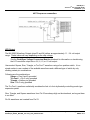
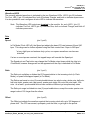
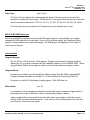
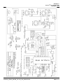
1
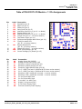
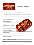
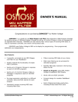
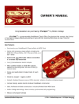
PedalSync™
Chips MV-55 and MV-55B
and
Module v1.1
Key Features
•
Offset control allows users to offset the
waveform against the incoming clock for
syncopation
•
Real-time control of potentiometers without
large waveform spikes due to extensive
proprietary smoothing and interpolation
algorithms
•
Backwards-Compatible with MIDI
•
Scalable - combine chips like building
blocks to make elaborate designs
•
Efficiently Designed to ensure Low part
count
•
Thru-Hole or SMT
•
Easy to create stand-alone pedals that can
be used traditionally and tested in-store
Tru-FootTM LFO waveform realistically
emulates the sound of a foot controlling a
wah-type expression pedal
•
Use PedalSyncTM and Tru-FootTM
trademarks on your devices and in
advertising
Duty Cycle control allows users to skew
waveforms (e.g. turn a triangle wave into a
sawtooth wave)
•
CadSoft Eagle footprint available for
module
•
Ultra-clean Analog (16-bit DAC) waveform
•
Stores and recalls Waveform, Clock/Pot
Status, Speed, Ratio, Offset, Duty Cycle,
and Bypass Status
•
MIDI, Tap, Pulse, and Pot control are all
possible
•
Unparalleled Tap Tempo Accuracy
•
Robust, 128 program storage
•
Simple, intuitive user interface
•
Five Simultaneous Outputs
•
•
•
Four separate waveforms - Sine, Square,
Triangle, and Tru-FootTM
[email protected]
PedalSync_MV-55_MV-55B_Tru-Foot_LFO_Datasheet.doc
© 2012 - MoltenVoltage.com - All Rights Reserved.
DRAFT v9.1
PedalSync™
Tru-FootTM LFO chip MV-55(B)
Datasheet - p.2
Five (5) Simultaneous Outputs
MV-55 and MV-55(B) have the following five simultaneous outputs:
•
Waveform Upright (pin 23)
•
Waveform Inverted (pin 24)
•
Tempo LED (pin 10)
Pin 10 will output a (0 - 3.1 volt) square wave that also reflects the duty cycle and will indicate the
offset amount.
The Tempo LED output is always pulsing, even if the chip is in Bypass mode. Further, in Clock
mode, the Tempo LED keeps pulsing even when no clock signal is being received.
Use a buffer if multiple circuits are driven off the Tempo LED.
•
Pin 14 - Synchronized Quarter-Note Pulse
Pin 14 will output synchronized quarter note (0 - 3.1 volt) pulses with a 50% duty cycle which are not
affected by the Duty Cycle, Offset, or Ratio controls.
In Pot/Tap mode, the pulses are continuously sent in time with the 1:1 ratio, quarter note interval.
In Pot/Tap mode, the pulses continue even if the chip is in Bypass mode. To synchronize the start
and stop of a sequencer circuit in Pot/Tap mode, connect Pin 18 via an inverter to the Clock Inhibit
pin of the 4017 Decade Counter chip rather than grounding that pin.
In Clock mode, the pulses are only sent when Clock data is being received and are synchronized to
the incoming Clock.
•
Pin 15 - Control Voltage (CV) Reset
To synchronize the reset of a sequencer circuit, connect Pin 15 to the Reset pin of the 4017 Decade
Counter chip.
In Pot/Tap mode, the CV Reset signal is sent upon the receipt of an initial Tap (i.e. the Tap Button
has not been pressed for at least 2.5 seconds). As such, a single tap can reset the sequencer.
In Clock mode, the CV Reset signal is sent after each MIDI Start command, whether or not Clock
information is being received.
[email protected]
PedalSync_MV-55_MV-55B_Tru-Foot_LFO_Datasheet.doc
© 2012 - MoltenVoltage.com - All Rights Reserved.
DRAFT v9.1
PedalSync™
Tru-FootTM LFO chip MV-55(B)
Datasheet - p.3
4017 Sequencer connection:
LFO Output
The MV-55(B) Waveform Outputs (pins 23 and 24) deliver an approximately 1.1 - 2.4 volt output
range. These values will vary depending on the chip voltage.
See the PedalSync Voltage Conversion Module datasheet for information on transforming
the LFO waveform output into a 0-5, 9, 10, or 12-volt output:
Users select Square, Sine, Triangle, or Tru-Foot™ waveform using a four-position switch. It is a
simple matter to use a subset of the available waveforms and a different type of switch by only
allowing certain pin combinations.
Following are the combinations:
Square = Pins 6 and 9 grounded
Tru-Foot™ = Pin 6 only grounded
Triangle = Neither pin grounded
Sine = Pin 9 only grounded
The Tru-Foot™ waveform realistically emulates the feel of a foot rhythmically controlling a wah-type
expression pedal.
Sine, Triangle, and Square waveforms from Pin 23 are always high on the downbeat, as long as there
is no offset.
Pin 24 waveforms are inverted from Pin 23.
[email protected]
PedalSync_MV-55_MV-55B_Tru-Foot_LFO_Datasheet.doc
© 2012 - MoltenVoltage.com - All Rights Reserved.
DRAFT v9.1
PedalSync™
Tru-FootTM LFO chip MV-55(B)
Datasheet - p.4
Waveform LEDS
The currently selected waveform is indicated by the two Waveform LEDs. LED 2 (pin 22) indicates
Tru-Foot, LED 1 (pin 12) indicates Sine, both off indicate Triangle, and both on indicate square wave.
It is also possible to use a red/green bi-color LED to indicate the waveform.
Note: The Waveform LED outputs are inverted on the module. As such, LED 1 (pin 12)
indicates Tru-Foot, LED 2 (pin 22) indicates Sine, both on indicate Triangle, and both off
indicate square wave.
Pots
Speed
(pin 2, pot0)
In Pot Mode (Clock LED off), the Speed pot adjusts the base LFO rate between 24 and 240
bpm. This range can be further adjusted using the Ratio control from 3 bpm to 960 bpm*.
* at very high bpm and extreme duty cycles, non-square waveforms can become
distorted
If a two or more taps are received, the tapped tempo will override the Speed pot.
The Speed pot and Tap button can change the Pot Mode output tempo while the chip is in
Clock Mode, however changes will not be apparent until the chip is switched to Pot Mode.
Ratio
(pin 3, pot1)
The Ratio pot multiplies or divides the LFO speed relative to the incoming clock (in Clock
Mode), or speed knob/tapped speed (in Pot Mode).
The Ratios are based on nine (9) musical subdivisions: two whole notes; whole note; half note;
half note triplet; quarter note (tap speed); quarter note triplet; 8th note; 8th note triplet; 16th
note. As a result, synchronized devices can oscillate at different yet complimentary rates.
The Ratio pot range is divided into nine (9) equal subdivisions, except the center quarter note
range is about 15% larger than the others.
Offset
(pin 4, pot2)
The Offset pot adjusts the waveform against the incoming clock with up to 360 degrees of
phase shift. The LFO can accent, syncopate, push the beat, or get right in the pocket.
[email protected]
PedalSync_MV-55_MV-55B_Tru-Foot_LFO_Datasheet.doc
© 2012 - MoltenVoltage.com - All Rights Reserved.
DRAFT v9.1
PedalSync™
Tru-FootTM LFO chip MV-55(B)
Datasheet - p.5
Duty Cycle
(pin 5, pot3)
The Duty Cycle pot adjusts the relative playback speed of the first and second half of the
waveform to make the output swing. The thirteen (13) duty cycle ratios correspond to the most
common musical subdivisions: 1/20; 1/8; 1/6; 1/4; 1/3; 3/8; 1/2; 5/8; 2/3; 3/4; 5/6; 7/8; 19/20.
The Duty Cycle pot can transform the Triangle wave into a sawtooth up or down.
MV-55 & MV-55B Differences
MV-55 and MV55B are identical except that MV-55 loads Program 1 automatically upon startup,
whereas MV-55B reads the four input pots, Clock or Pot/Tap mode switch, and Waveform Select
switch on startup and sets the output accordingly. MV-55B ignores the Speed pot if the chip is in
Clock mode at startup.
User Interface
Program Storage
The Tru-Foot™ LFO chip stores 128 programs. Programs are stored by toggling the Write
Switch (pin 16) or upon a command from the PedalSync Master Control chip MV-58(B). When
using the Write Switch, the program is written to the currently-selected program number.
Program Recall
Programs are recalled using the PedalSync Master Control chip MV-58(B), standard MIDI
Program Change messages on Channel 15, or the PedalSync 4 Presets chip (MV-59).
On power up, the MV-55 chip always loads program 1, MV-55B does not.
Write switch
(pin 16)
It is possible to use a momentary pushbutton for the Write switch, however a toggle switch is
recommended to make it difficult for users to accidentally program a setting.
Using a toggle switch, the user will close the switch, then open it again to write the current
settings to the currently selected program. If the switch is in the closed position, the user will
need to open, close, then open again.
[email protected]
PedalSync_MV-55_MV-55B_Tru-Foot_LFO_Datasheet.doc
© 2012 - MoltenVoltage.com - All Rights Reserved.
DRAFT v9.1
PedalSync™
Tru-FootTM LFO chip MV-55(B)
Datasheet - p.6
Status LED
(pin 17)
The Status LED is normally on. When a program is written, the Status LED will blink.
Whenever the potentiometers are not stable (i.e. when they are moving or have recently
moved), the Status LED will turn off until they become stable again. Each pot will stabilize
after approximately three (3) seconds of no motion.
Tap button
(pin 11)
When in Pot/Tap Mode (Clock LED off), the tempo can be adjusted by tapping a momentary
switch two or more times. The timing between the last two taps will determine the tempo. The
tap button times out after approximately 2.5 seconds. If the Speed knob is moved after a
tempo is tapped in, the Speed knob will override the tapped tempo.
A single tap will reset the waveform to the beginning. This allows users sync up the waveform
with a single tap or when a CV clock starts transmitting. Again, this is only in Pot/Tap mode.
The chip syncs with incoming taps, and switches from Pot to Tap mode, at the moment of the
second tap.
The Speed pot and Tap button can change the Pot Mode output tempo while the chip is in
Clock Mode, however changes will not be apparent until the chip is switched to Pot Mode.
Tempo LED
(pin 10)
Tempo LED turns on at the beginning of the waveform (max. voltage) and off at the center of
the waveform. As such, the Tempo LED shows Offset and Duty Cycle adjustments.
To monitor the waveform on the output buffer rather than with the Tempo LED, use an op amp
buffer/follower circuit for the LED.
Clock or Pot/Tap mode switch
(pin 25)
The LFO timing source is selected with a switch:
[a] Clock, or
[b] Speed Pot and Tap Button
When the pin is grounded, Pot/Tap is selected
Disconnecting the pin places the chip into Clock mode.
[email protected]
PedalSync_MV-55_MV-55B_Tru-Foot_LFO_Datasheet.doc
© 2012 - MoltenVoltage.com - All Rights Reserved.
DRAFT v9.1
PedalSync™
Tru-FootTM LFO chip MV-55(B)
Datasheet - p.7
When a program is read from memory the Clock or Pot/Tap mode is recalled. If, for example,
the program uses Clock mode and the pin is already grounded, the user will need to toggle the
switch twice to enter Pot/Tap mode.
The program default is Pot, allowing stand-alone effects that do not need an external clock
signal. If the design does not use an incoming clock, the Clock/Pot pin should remain
grounded.
In Clock mode, the LFO starts automatically and runs even when no clock is coming in. The
tempo stored and recalled from memory will be the tempo that was happening at the time it
was stored.
In Clock mode, the waveform resets upon each MIDI Start command.
Clock Mode LED
(pin 26)
The Clock Mode LED will be lit when then LFO is controlled by the incoming clock. When the
LFO is controlled by the Speed knob and/or Tap button the LED is not lit.
When in Clock Mode, the tempo is controlled by an incoming PedalSync or MIDI Clock at pin
21. If no Clock is present, the LFO runs at the last incoming value, which is also stored when
a program is written.
Bypass button
(pin 7)
Pressing the Bypass button sends both waveform outputs to the maximum voltage as well as
turning off pin 18. Pressing again re-starts the waveform outputs.
The program default for the Bypass Button is ON. If using the Relay Bypass chip (MV-57), this
corresponds to having the device engaged.
Bypass Output or LED
(pin 18)
The Bypass LED is illuminated when the LFO is being sent. Pin 18 can alternatively be used
to control the PedalSync Relay Bypass chip (MV-57). Pin 18 can also be connected via an
inverter to the Clock Inhibit pin of a 4017 Decade Counter chip to synchronize the start and
stop of a sequencer circuit.
If more than one circuit is connected, be sure to buffer the output.
[email protected]
PedalSync_MV-55_MV-55B_Tru-Foot_LFO_Datasheet.doc
© 2012 - MoltenVoltage.com - All Rights Reserved.
DRAFT v9.1
PedalSync™
Tru-FootTM LFO chip MV-55(B)
Datasheet - p.8
Waveform Select switch and LEDs
See the LFO Output section, above.
Control Voltage (CV) Input
In Pot mode, a Control Voltage (CV) can be used to continuously control the tempo. Have the control
voltage trigger a 4066 CMOS Quad Bilateral Switch and ground pin 11 (the Tap button input). In the
alternative, consider an optocoupler or transistor.
The ideal CV signal will have a 50% duty cycle At the downbeat, pin 11 should be grounded. If this
is not the case, invert your CV signal.
The LFO adjusts immediately upon the latest tap.
Program Defaults
•
Not Bypassed, LFO output on
•
Pot/Tap mode
•
Sine wave
•
50% Duty Cycle
•
Offset = zero
•
1:1 Ratio
•
Speed - 120 bpm
MIDI - Backward Compatibility
The exclusive MIDI channel for the PedalSync system is MIDI Channel 15. MIDI Program
Change messages sent on any other channel will be ignored by the chip.
The Tru-Foot LFO chip also responds to standard MIDI Start, Stop, and Clock messages.
Note that in Clock mode, the chip will not function properly outside of the 24-240 bpm range limits.
[email protected]
PedalSync_MV-55_MV-55B_Tru-Foot_LFO_Datasheet.doc
© 2012 - MoltenVoltage.com - All Rights Reserved.
DRAFT v9.1
PedalSync™
Tru-FootTM LFO chip MV-55(B)
Datasheet - p.9
Electrical Considerations
9 volts DC maximum on the power input to the module. At least 7.5 volts input.
The schematic below shows the necessary, as well as optional, connections. Note that you can use
different resistors for the LEDs depending on the type of LED used, but do not exceed the current
limits of the underlying chip as set forth below.
If you require brighter LEDs, consider using buffers or ultra-bright LEDs.
The datasheet for the underlying dsPIC33FJ64GP802 chip can be found here:
http://www.microchip.com/wwwproducts/Devices.aspx?dDocName=en532310
If more than one circuit will be controlled by the LFO, be certain to buffer the output (e.g. with op amp
followers) to ensure a consistent output signal to each circuit.
Noise
It is very important to properly filter your power supply as shown in the schematic.
To minimize digital noise bleeding into your audio circuit, be careful to run three separate grounds as
indicated on the schematic.
Follow proper PCB layout design rules and isolate the digital and analog sections of your circuit as
much as possible, connecting the grounds at a common point at the power supply.
The Ferrite on AVDD may not be totally necessary but will quiet down and stabilize the analog
voltage. Thru hole values for ferrites are limited and may not be available beyond 800 ohms. The
recommended part which appears on the Tru-Foot LFO Module is a 2.5 KOhm Impedance 50mA
Ferrite, such as Murata P/N BLM18BD252SN1D.
[email protected]
PedalSync_MV-55_MV-55B_Tru-Foot_LFO_Datasheet.doc
© 2012 - MoltenVoltage.com - All Rights Reserved.
DRAFT v9.1
PedalSync™
Tru-FootTM LFO chip MV-55(B)
Datasheet - p.10
Module
The Tru-Foot LFO Module does not include all the external connections shown in the schematic. The
available connections are set forth in the Table of TRU-FOOT LFO Module v 1.1 Pin Assignments,
below.
Input and Output header pins are provided for all necessary connections, but series resistors are
necessary for many of the LEDs. Please refer to the Table of TRU-FOOT LFO Module v 1.1 Pin
Assignments for more information.
The Module accepts 9-volt DC input, and provides regulated, filtered power for the 3.3 and 5 volt
circuits, as well as off-board connections for both voltages and the isolated grounds (AG and DG).
Refer to the schematic, below, for information on connecting pots, MIDI Jacks, and switches.
[email protected]
PedalSync_MV-55_MV-55B_Tru-Foot_LFO_Datasheet.doc
© 2012 - MoltenVoltage.com - All Rights Reserved.
DRAFT v9.1
PedalSync™
Tru-FootTM LFO chip MV-55(B)
Datasheet - p.11
[email protected]
PedalSync_MV-55_MV-55B_Tru-Foot_LFO_Datasheet.doc
© 2012 - MoltenVoltage.com - All Rights Reserved.
DRAFT v9.1
PedalSync™
Tru-FootTM LFO chip MV-55(B)
Datasheet - p.12
Table of TRU-FOOT LFO Module v 1.1 Pin Assignments
Pin
1
2
3
4
5
6
7
8
9
10
11
Label
SP
RA
OF
DU
W1
BP
W2
TM
TA
14
CL
12
BO
13
14
15
ST
WR
15
Pin
30
29
28
27
26
25
24
23
22
21
20
19
18
17
16
Label
AV
AG
AA+
CP
T2
T1
F2
F1
I4
I5
5V
5G
+V
GD
Connection
Speed Pot (pin 2)
Ratio Pot (pin 3)
Offset Pot (pin 4)
Duty Cycle Pot (pin 5)
Waveform Select Pin 1 (pin 6 - no diode)
Bypass Switch (pin 7)
Waveform Select Pin 2 (pin 9 - no diode)
Tempo LED (pin 10 - no series resistor)
Tap Button Input (pin 11)
Synchronized Quarter-Note Pulse (pin 14)
Clock/Pot status LED
(pin 26 - no series resistor)
Bypass Output/LED
(pin 18 - no series resistor)
Status LED (pin 17 - no series resistor)
Write (PGM) Switch (pin 16)
Control Voltage (CV) Reset (pin 15)
Connection
Analog Power Rail (AVDD)
Analog Ground Rail (AVSS) [AG]
Waveform output Inverted (pin 24)
Waveform output Upright (pin 23)
Clock/Pot Toggle Switch Input (pin 25)
Pin 5 - MIDI Thru Jack 2 (buffered & 220 ohm series resistor)
Pin 5 - MIDI Thru Jack 1 (buffered & 220 ohm series resistor)
Waveform LED 2 (buffered, inverted - no series resistor)
Waveform LED 1 (buffered, inverted - no series resistor)
Pin 4 of Input MIDI Jack
Pin 5 of Input MIDI Jack
5 Volt Rail - for MIDI Thru
Digital 5 volt ground [DG]
9 volt Power Supply Input
Common Ground (Power Supply)
[email protected]
PedalSync_MV-55_MV-55B_Tru-Foot_LFO_Datasheet.doc
© 2012 - MoltenVoltage.com - All Rights Reserved.
DRAFT v9.1
PedalSync™
Tru-FootTM LFO chip MV-55(B)
Datasheet - p.13
[email protected]
PedalSync_MV-55_MV-55B_Tru-Foot_LFO_Datasheet.doc
© 2012 - MoltenVoltage.com - All Rights Reserved.
DRAFT v9.1
PedalSync™
Tru-FootTM LFO chip MV-55(B)
Datasheet - p.14
Specifications
4.835 Khz sample rate with 256x oversampling, resulting in an ultra-clean 1.237 MHz interpolated
analog waveform
90dB signal to noise ratio
128-Tap FIR Current-Steering Analog Reconstruction Filter
Pin Voltage and Current Limits
Pin
1
2
3
4
5
6
7
8
9
10
11
12
13
14
15
16
17
18
19
20
21
22
23
24
25
26
27
28
Max Voltage
5
3.3
3.3
3.3
3.3
3.3
3.3
GND
3.3
3.3
3.3
3.3
3.3
5
5
5
5
5
GND
N/A
5
5
3.3
3.3
3.3
3.3
GND
3.3
Max Current*
4
12
12
12
12
4
4
4
25
12
4
12
12
4
12
12
12
12
4
4
4
4
* 200 mA max current sink or source for the whole chip at any given time, except on the Module
which is limited to ~50 mA. Keep your currents low to minimize noise.
[email protected]
PedalSync_MV-55_MV-55B_Tru-Foot_LFO_Datasheet.doc
© 2012 - MoltenVoltage.com - All Rights Reserved.
DRAFT v9.1
PedalSync™
Tru-FootTM LFO chip MV-55(B)
Datasheet - p.15
Power Consumption (typical) ~ 90mA
see also:
Microchip dsPIC33FJ64GP802 Datasheet
http://www.microchip.com/wwwproducts/Devices.aspx?dDocName=en532310
Module Dimensions
Circuit board:
1.7 x 1.6”
Header pins are spaced 0.1” and the two header strips are 1.5” apart
A complete set of CadSoft Eagle footprints for PedalSync modules is available for download at:
www.PedalSync.com
Related Products
•
Use with Voltage Conversion Module to convert output voltage to 0-5v, 9v, 10v, or 12v
•
Use with Four Pots chip (MV-56) to save LFO depth and center settings.
•
Use with 4 Presets chip (MV-59) to make a stand-alone device that can store and recall four
programs. MV-59 can be connected directly to MV-55(B) Pin 21 with a 330 ohm resistor in series
in stand-alone devices.
Support
[email protected]
DISCLAIMER
Information contained in this publication regarding device applications and the like is provided only for
your convenience and may be superseded by updates. It is your responsibility to ensure that your
application meets with your specifications. MOLTEN VOLTAGE MAKES NO REPRESENTATIONS
OR WARRANTIES OF ANY KIND WHETHER EXPRESS OR IMPLIED, WRITTEN OR ORAL,
STATUTORY OR OTHERWISE, RELATED TO THE INFORMATION, INCLUDING BUT NOT
LIMITED TO ITS CONDITION, QUALITY, PERFORMANCE, MERCHANTABILITY OR FITNESS
FOR PURPOSE. Molten Voltage disclaims all liability arising from this information and its use. No
licenses are conveyed, implicitly or otherwise, under any Molten Voltage intellectual property rights.
PedalSync, Tru-Foot, Molten Voltage, Visionary Effects, “Design simple Design sublime”, and “the future just showed up”
are all trademarks of Molten Voltage. [email protected]
[email protected]
PedalSync_MV-55_MV-55B_Tru-Foot_LFO_Datasheet.doc
© 2012 - MoltenVoltage.com - All Rights Reserved.
DRAFT v9.1