1
Principles of Operation
Main Circuit Board
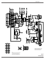
See Figure 109 (at the end of this section) for the schematic diagram of the
warming system main circuit board. The main circuit board consists of:
•
DC Power Supply Circuit
•
Control Logic Circuit
•
Automatic Temperature Stepdown
•
Temperature Control Circuit
•
Liquid Crystal Display (LCD) Hour Meter
There are three connectors on the main circuit board:
•
J1 – connects the main circuit board to the control panel
•
J2 – connects the main circuit board to the AC power line circuit, the
heater, and the blower
•
J3 – connects the temperature control circuit of the main circuit board to:
–
–
YS1 400 series thermostat
Over-temperature test port
DC Power Supply Circuit
The 120 VAC enters the main circuit board through J2, pins 3 and 4. The power
supply circuit consists of:
•
F1 fuse, located in the primary of the transformer
•
D7 bridge rectifier
•
VR1 12 VDC voltage regulator
WARNING: Dangerous voltages (120 VAC) are exposed during this
procedure. Exercise extreme care not to come in contact with the 120 VAC.
Servicing is only to be done by qualified personnel.
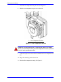
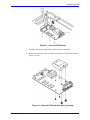
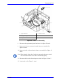
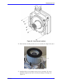
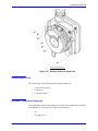
In case of warming system unit failure (no lights), the presence of 12 VDC should
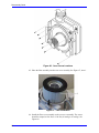
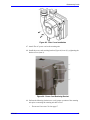
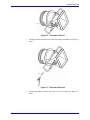
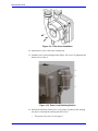
be verified. This can be done by opening the warming system unit. See
Figure 107. Connect a voltmeter to the test points 1 and 4 of J4 (test point J4-4 is
ground and test point; J4-1 is 12 VDC). J4 is located on the circuit board
assembly.
94