1
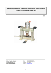
Film-Tech
The information contained in this Adobe Acrobat pdf
file is provided at your own risk and good judgment.
These manuals are designed to facilitate the
exchange of information related to cinema
projection and film handling, with no warranties nor
obligations from the authors, for qualified field
service engineers.
If you are not a qualified technician, please make no
adjustments to anything you may read about in these
Adobe manual downloads.
www.film-tech.com
f.8.-8€ll e lltuell
M 0 D E t6 0 e
' l6 m m A r c P r o i e c t o r
MANUAL
SERVICE
SPAREPARTSLISTS
CARE& MAINTENANCE
tTD.
INDUSTRIES
RANK PRECISTON
Cine & OPtical Division
37 - 4I MORTIMERSTREET'
LONDON,W.t.
3rd EDITION
JUNE I955
'
:,:.:i
'.i:
-. .,
":.:.:
-- r:J
Introduction
se have pleasure in presenting for servlce pu.rposesthe forrowing information:( 1 ) Service Instructions
covering the majority
of the Model 609 Projector.
of assemblies and parts
As there are many assbmblies and parts which are sonnon to both the
Model 609 and Model 621 Projectors,these
instructions
where applicable are cross referenced to the Mode1 621 Service Manual.
( 2 ) G. B. Bell & Howell Model 609 Arc Projector.
Spare parts
List
and
Exploded Views.
( 3 ) G.B. BelI & Howell Model 621 Service Manual which covers most of the
gear case and sone other assenblies
Model 609 and Model 62I projectors.
which are commonto both the
(4)
circuit
Diagram for the Modet 609 Mechanismhead and Take up Assembly.
(5)
Circuit
Diasram for the Model 609 Amplifier.
(6)
Circuit
Diagram for the Model 609 Arc Rectifier.
(7)
Spare Parts Catalogue for the G.B. Kalee Universal
Arc Lamp.
The Model 609 Arc Lamp is identical
in most respects to the G. B.
Kalee Universal Arc Lamp, and the Spare Parts Catalogue which is
issued, will for all practical purposes be most useful when ordering
spare parts and also for maintenance purposes.
In the main" the
only differences wirl be the dowser assembries, and the inclusion of
a pilot lamp in the Modet 609 Arc Lamp. We hope to publish shortly
a leaflet covering more fully these variations.
THE
f.8.-8el( a *bue6
MODEL 509
| 6 mm ARC PROJECTOR
SERVICEINSTRUCTIONS
SECTION I
PROCEDURE
DISASSEMBLY
Disassembly
Procedure
THE PROJECTOR
IIEAD.
(1)
REiIOVALOF IIOTORI'NIT
a.
R , e m o v et h e c o v e r p l a t e N o . 5 0 1 4 9
(Fig.9) at the rear side of the casting.
Disconnect the motor wires from the terminal
strip.
b. Removethe four screws (2) No. M50137
& (2) No. 1587 (Fig.4) holdingthemotor unit
to the front of the gear case. the motor can
now be taken from the Projector Head. The
drive coupling No. M025119(Fig.4)connecting
the rear end of the motor shaft to the cooling
fan shaft should be removed. The gate operating block No. 5160 (Fig.41 which is located
in the channel at the back of the lens carrier
should be removed to avoid any possibility
of this part being lost.
2.
No. 5267 (Fig.1) situated at the top and
bottom of this part.
There is a snall spacing washer No. 4258 under the head of each
screw. Removeand handle carefully to prevent
loss of the washers when the screws are removed.
b. \{ith the removal of the two fillister
head ssrews No. 5266 (Fie.1) situated at the
rear of the gear case, immediately above and
below the blower shaft, the gear case can
now be separated from the blower case. Care
should be taken when parting these two asof damage
semblies to aioid the possibility
io the fibre gear No.03135 (Fie.3). Move the
gear case slj.ghtly until the counter gear
breaks mesh with the pinion gear No. 2L328
(Fig.7) fitted to the fan shaft, and until
the dowel pin No. 9171 (Fig.7) on the rear
side of the fan case is free from the dowel
hole.
REITOVAL
OF GEABCASEAND BLOf,ERASSEIIBLY
4.
a. The 470 ohm Motor resistance assembly
N o . 0 4 7 5 8 R(, F i s . 7 ) w h i c h i s h o u s e d b e l o w t h e
fan housing No.15709 (Fig.7) should be disconnected fron the main terminalstrip.
b. Lay the Projector on its side and remove the cover pLate No. 50136 (Fig.9) from
the base of the soundhead assembly.
c.
R e m o v et h e t h r e e s c r e w s a n d l o c k
washers which are located inside the soundhead directly beneath the gear case.
d. The gear case and blower assembly is
now free of the soundhead assembly.
3. REMOVAL
OF GEARCASEFBOMFAN HOUSING
ASSEIIBLY.
a. The film guide rail No. 5641 (Fie.1)
will be freed by the removal of the two screws
DIS-ASSEMBLY
OF ilOTOBUNIT.
a. Removethe two screws No. 10349 (Fig.4)
holding the cover lio. 50132 (Fie. 4) on the
front end of the motor. Use a 3BA Allen key
and loosen the two AIIen set screws in the
motor extension shaft No. M50140(Fig. 4).
The shaft can now be removed.
b. fite motor governor No.M50139is locked
to the shaft by the two 4BA Allen set screws.
In addition there is a hexagon nut No. 9117
(Fig. 41 which is locked in place by two
prongs of the locking washer No. 10390 (Flg.4)
behind it.
Firstly straielten these prongs,
hold the governor carefully,
and remove the
hexagon nut.
The two Allen screws in the
hub of the governor should now be loosened
and the governor removed. Removespacer
No. t5721 (Fig.a) immediately behind the
governor hub. Remove the three governor
brushes No.4664(Fig.4) fromthe brush holders
in the motor cap. Note fhat these brushes
must fit freely in the holders.
5.
REIITOYAL
OF BNUSNBOXHOUSING.
a. Before removing the brush box assembly
N o . M 5 0 1 3 1( F i g . 4 ) f r o m t h e b o d y o f t h e m o t o r ,
the two notor brushes should be removed.
b . R e m o v ef o u r s c r e w s N o . 9 ? 1 8 ( F i g . 4 1
securing the brush holder castlng to the motor
body. Ease the complete assenbly awal from
the motor bousing. Note the manner in which
the wires leave the field, and the way they
are placed to avoid contact with any moving
part.
It will not be possible to disconnect
the three field coil leads from this assembly.
c. The armature No. M50133(Fig.4) can
now be withdrawn from the motor. Note the
spacer No. 15721 (Fig.4) which is on the
front end of the armature shaft, and the
spring washer No. 15706 (Fig. 4) which is
Ieft in the ball race bousing of the motor
casting.
Care should be taken that these
itens are fitted correctly when re-assembly
takes place.
6.
BE}IOVALOF }IOTORFIELI}.
a . T o r e m o v e m o t o r f i e l d M 5 0 1 3 4( F i g . 4 )
unscrewthe four field retaining nuts No.5201
(Fig.4)and withdraw the field fron the
motor housing. Note the manner in which the
wires leave the field, and the way they are
placed to avoid contact with any moving part.
The lens carrier retainers No. 11?99
1) are now accessible, and must be
unscrewed. Lift straight up on the lens
carrier assembly to remove it.
c.
(fig.
8.
BEIIOVALOF SPB0CXET
GUAnDS,FILil BOLLER,
TENSIONCLIPS ANDAPEBTURE
PLATE.
a. To renove the upper and lower sprocket
guards No. 04946 (Fig.2) unscrew the two
screws No. 1175? (Fig.2) vfrich are locatedin
the centre of each guard, and in the end of
the sprocket shafts.
As the guards are
removed note the spring clips No. 16243
(Fig.2) and washersNo.16244(Fig.2) located
beneath the hinge part of the guard.
b. Removethe upper and lower film strippers No. 11?62 (Fig. 2). These parts are interchangeable.
c. Unscrew the two fillister
head screws
No. 5021 (Fie.1) holding the upper No. 03462
(Fig.1) and lower No. 03463 (Fig. 1) film
tension clip assemblies. These two clips
are situated on the film gate thrust sfing
No. 4255 (Fie.1) which is also held in place
by the same two screws.
DIS.ASSEUBLYOF GEABCASE.
d. The back edge of the film gate thrust
spring rests against the inner edge of the
aperture plate No.11852 (Fig.11 and thus
holds it in position on the gear casre assembly
Ilhen the film gate thrust spring has been
removed the aperture plate can be separatgd
from the gear case.
7.
9.
REIUOVAL
OF FILM GUIDESANII LENSCABBIER
& . R e m o v et h e p r e s s u r e p l a t e a s s e m b l y
by pulling on the novable visibie metal
frame.
b. To remove the lens carrier assembly,
it is necessary at first that the film guides
No. 11761 (fig.21 be removed. Unscrew the
four screws No. 7493 (Fig.2) holding these
two items, and slip the upper and lower filnr
guides from position.
lhese guides are the
sane, and can be interchanged.
BEilOVALOF FBAIII SHAFTAND rI{OB
.a. 0n the back of the aperture plate are
two prongs which fit over the eccentrice of
the framer shaft and knob assembly No. 03464
(fig.1).
After the aperture plate has been
removed, the framer shaft and knob assembly
can be withdrawn from the outside of the gear
case casting.
10.
BEIIIOVAL
OF SPBOCIGTS.
a.
Each of the sprocket assemblies
No. 03461 (Fie.2) is locked in place by two
Allen set screws, which are located in the
hub of the upper and lower sprocket gears.
Use a 2BA Allen key to loosen these screws.
The sprockets can be slipped from the end of
the shaft. Note that the end of the sprocket
stem locates in the hub of the gear. Remove
the thrust washer No. 6419 (Fie.2) located
between the end of each sprocket and gear.
1I,
REilovAL oF SHUTTEBAI{II Sf,UTTIS
a. To removOthe hexagon nut No. 5112
(Fig.3) from the shuttle shaft a special off
set wrench should be used to hold the cam
shaft below the flicker shutter while the
hexagon nut is removed.
b. In the event of a suitable wrench not
being available,it
is possible to remove the
nut if the shutter can be held still
by an
alternative
method. Every care must be
taken to avoid damage to the flicker
shutter
and shuttle shaft.
c. IThen the hexagon nut is removed lift
offthe two shutter supports No.12789 (Fig.3)
and flicker shutter No. 12?88 (Fie.3).
Note
that the stud on the bottom of the lower
shutter support engages the indents of the
flat surface on the shuttle shaft, and that
the stud on the botton surface of the upper
shutter support extends through the hole in
the shutter, and into the recess in the top
of the lower shutter sqlport.
The above
assembly should be carefully observed, so
that the various parts can be re-assembled
in the sane nanner.
d. Lift up the oil baffle assemblies No.
9558 (Fis.3) and No. 01078 (Fig.3)
elear
the gear case. Note the manner in which the
oil baffle engages the slot in the gear case
casting.
e. Unscrew the two fillister
head screws
No. 5123 (Fie.3) holding the shuttle guide
pins No. 5113 (Fig.3) in place. Ihe shuttle
No. 8933 (Fig. 3) can now be lifted clear of
the shutter shaft and the euide pins removed.
12.
DIS.ASSEiIBLYOF THE BLOIEBUNIT.
a. Removethe light baffle No. 15783
(Fle.5) which is held in place at rear of
this assembty by four fillister
head screws
N o . 1 6 9 3 0 R( F i g . 5 ) .
N e x t r e m o y eh e a t f i l t e r
housing No. 15782 (Fig.6) which is attached
to the blower casting by three fillister
head screws No.3225 (Fig.6).
b. The fan shaft No. M50269(Fig.?) is
removed in the following manner. Removethe
f a n b e a r i n g c a p N o . M 5 0 2 8 3( F i e . 6 ) a t t h e
rear end of the blower shaft, thus exposing
the ball race No. 10356 (Fig. 6).
the shaft
is locked to this ball race by a hexagon nut
No.12087 (Fig.6).
R e m o v et h e n u t a n d a l s o
the three fillister
head screws No. 1361
(Fig.6) holding the fan intake casting
No. 50282 (Fig.6) to the main body. This
castlng can now be withdravn from the blower
casting The ball race which is housed in
the intake casting can now be removed. Note
the preload spring No. 15705 (Fig.7) housed
in this casting beneaththeball race No.4373
(Fie.7).
c. fire cooling fan No. 05002 (FiC.6) and
spacer washer No. 15703 (Fig.6) can now be
removed from the shaft No. M50269(Fig.7).
Note the further spacing washer No. 15704
(Fig.7) which is situated imnediately behind
the front ball race of the fan shaft.
Care
should be taken when re-assembling this shaft
to ensure that these spacers are fitted
in
their correct positions.
d.
To remove the cooling fan shaft
N o . M 5 0 2 6 9( F i g . 7 ) t h i s s h o u l d b e p r e s s e d
out in a forward direction.
e. If it is found necessary to remove
the pinion gear No. 21328 (Fig.7) from the
shaft, the utmost care should be taken to
avoid any possible damage occurring to the
cir-clip washerNo. 21331 (Fie.7) holdine
the pini.on gear and washers No. 5193 (Fig.7)
in place.
The pressure applied by the compression spring No. 21330 (Fig.7) against
this washer must be relieved before the
washer 21331 can be removed.
13.
DIS-ASSEilBIYOF TIIE SOUNDHEAD.
a. The notor switch No. b0426 (Fig.10)
which is housed in the sound head in accessible by removing the cover plate No. b0120
(Fie.9).
This is situated at the rear end
of the sound head, and is held in position
by four oval headed screws No. 1b8? (Fig.9)
the locking nut on the switch should be removed, thus enabling the switch to be partially withdrawn from tbe casting, so that the
soldered leads can be disconnected.
14. BETOVESOI'NDIIRUTIBEARINGSHAFTASSENBLY
ANI' FLY 'NEEI.
a. At the back of the sound head casting
is a ball bearing retaining cap No. 13656
(Fig.10) held in place by three fillister
head screws No.5266(Fig.10). Removethe cap
and phosphor bronze plunger No.13661 (Fig. 10)
together when its loading spring No. 136b9
(Fie.10) will be exposed.
b. Removethe three fillister
head screws
l{o. 5266 (Fig.10) which hold the front bearing support in place.
The lieht shield
No. 12145 (Fie.10) will come off at the same
t ime.
c. Partly withdraw the sound drum until
the hexagon nut which holds the fly wheel on
the shaft is accessible.
The front bearing
is part of the sound shaft assembly, and will
out of position.
Iift
Before the sound drum
shaft assembly No. 04169 (Fig.10) can be removed from the sound head a Tonny Bar w111
have to be inserted in the hole in the sound
shaft, and the fly wheel released by undoing
the hexagonal nut.
The fly wheel can then
be slipped up fron the end of the shaft.
d. The sound drum and shaft No. 04169
(F'ig.10) should be considered a unit, and
should not be taken apart.
If it becomes
damagedto such an extent that sound quality
is affected, the entire assembly should be
replaced.
Any attempt to separate the sound
drum fron the shaft will result in loss of
time, and w1Il be followed by difficulties
which cannot be overcome. lttese sound drum
and shaft assemblies are carefully assembled,
balanced, and aligned at the factory, and
can be replaced only as a unit.
15.
REIIIOVE
BOLLERIOIG ANDARiI ASSEIIIBLY.
a. It is possible to adjust or repair
the roller yoke and ann assembly, but this
unit requires an extraordinary amountof care.
It is precisely set for run out and smoothness of operatlon.
Before disturbi.ng these
parts,make every attempttotrace the trouble
to its real source, which, in turn, may save
tine and dlfficulty.
b. The roller yoke and arm assembly No.
03690 (Fig.9) is removed by loosening two
sets screws on the knurled collar, and withdrawing the entire assembly from the pivot
Do not remove this assembly or tamper
stud.
with its critical
adjustment unless it fails
to function satisfactorily.
Unless the ro1ler will not revolve, it is unlikely that any
adjustment whatsoever is needed.
16.
RETOYEOPTICALSLIT.
a. The optical slit assembly No. 02678
(Fig.10) is assenbled at the factory.
It is
positioned in the sound head by means of
several delicate precision instruments, and
i s s e t t o e n s u r e t h e m a x i m u me f f i c i e n c y .
Note that the tube is locked in place.with
the screw No. 5893 (Fig.10) and that a coating of cement has been placed over the screw
head. Experience has shom us that it is not
satisfactory
to attempt the setting of this
tube except at the Factory or with a special
sound optics setting gauge.
IT.REHOYALANDIIIS-ASSE}IBLYOF FILII SNUBBEN.
a. The film snubber assembly can be removedas a separate unit. To do so the three
filllster
head screws No.5266 (Fig.10)should
be renoved. the entire snubber assembly No.
02674 (Fig.9) can now be removed fron the
sound head.
DIS.ASSEiIBLYOF IIOTOBTAKE UP UNIT
18.
UNIT.
REIITOYAL
OF THE IIIOTOR
a. Removethe cover plate No.50250 (Fie.
11) at the rear of the take up casting. Disconnect four motor leads from the terminal
head screws
strip. Removethe four fillister
No. 50156 1pig.12) holding the motor to the
The motor
main body of the take up unit.
assenbly is now free of the main unit.
b. To remove the take up drive mechanisn
from the motor, three fillister
head screws
No. 5266 (Fig.13) holding the gear box casti.ng to the front end of the motor should be
removed. This assembly can now be eased away from the motor casti.ng.
19. REIIOVALOF ABMATTJBE
ANI' FIELD COIL FBOII
TAKE UP IIIOTOR.
&. Removethe notor brushes. Removethe
head screws No.9098 (Fig. 12)
two fillister
holding the motor brush housing to the main
bodyofthemotor. The brush housing No.02158R
(Fig.12) can now be eased off.
Care should
be taken on re-arisembly of this brush holder
unit to avoid the wires eonnected to the
brush holders coming into contact with the
armature assembly.
b. Grip the armature No. 9090 (Fig.12)
and remove fillister
head screw No.112 (Fie.
12) holding the spiral sear No. 02519 (Fie.
12) to the front end of the armature shaft.
A key way is cut into the front end of the
armature shaft, into which a dowel pin fitted to the spiral gear engages. IVith the
spiral gear renoved the annature can be withdrawn from the motor.
c. To renove the motor field coil No.9092
(Fig.12)unscrew the two field retaining nuts
No. 5201 (Fig.12)and withdraw the field coil
from the'motor housing. Note the manner in
which the wires leave the field,
and the way
they are placed to avoid contact with any
moving part.
ffiffiffi
THE
f.8.-8cl( € 1fuarc6
MODEL 509
| 6 mm ARC PROJECTOR
SERVICEINSTRUCTIONS
SECTION2
PROCEDURE
REASSEMBLY
Reassembly
Procedure
1. INSTALL ITOTOBFIEID , ABTATI'BEAI{D BBUSH
BOXHOUSING.
c. Check to see that the three field wires
connected to the brush box housing will not
rub against the armature as the housing is
pressed into posltion.
a. fnsert the four field coil leads into
the special outlet channeL at the rear of
motor casting No. 50130 (Fig.41.
h. With the brush box housing inposition,
fasten the assenrbly to the notor housing with
the four screws No. 9718 (Fie.4).
b . T h e m o t o r f i e l d s N o . M 5 0 1 3 4( F i g . 4 )
guided into place over
should be carefully
t h e l o c a t i n g s t u d s N o . M 5 0 3 3 7( F i g . 4 ) a n d
clamped in position by the four retaining nuts
No. 5201 (Fig.41. Checkthe position of the
leads at the outlet point to ensure that they
will not make contact with any revolving part.
i.
AGAIN CIIECK 10 SM I}IAT ALL WIRES ARE
CI.EAR,OF ITIE ARMAN]RE.
REASSEIIBLE
IIIOTOBANI} GOVERNOB.
c. Solder the three wires at the front
end of the field coil to their respectlve
positions on the brush holders and speed
switch No. 13788R (Fie.4).
d. Before assembling the armature No.
M50133 (Fig.4) into the motor housing, check
to see that the spring washer No.15706 (Fie.
4) is in position in the rear ball race
housing.
e. Insert the end of the armature shaft
with the ball race No.4373 (Fig.4) and cooling fan No. M50243 (Fig.a1 attached through
the notor field.
Carefully press the armature inwards, so that the rear ball race
enters its housing squarely.
f.
Before olacing the brush box housing
No. M50131 (Fic.4) over the front end of the
armature shaft, check to see that the spacer
No.15721 (Fig.41 is in position on the shaft
(next to the comnutator).
2.
INSTALLITOTOB
BRUSHES.
a. Insert the motor brush No. 12918(Fig.4)
and spring No. 12909 (Fig.4) into the square
hole of the brush holder.
If the brush is
not new be sure the concave contact surface
of the brush will fit the curve of the commutator.
fire brush and spring are held in
place withthemotor brush cap No.11888 (Fig.
4).
3.
INSTALL GOVERNOR.
Assemblethe three governor brushes No.
4664 (FiC.4) ensuring their free movementin
the holders.
a,
b. Slip spacer No. 15721 (Fie.4) on to
the end of the armature shaft followed by
the governor No. M50139 (Fig.a).
c. Place the locking washer No. 10890
(Fig.4)over the threaded portionofthe
armature shaft,and screw the hexagon nut No.911?
(Fig.4; on to the shaft.
Insert a suitably
shaped piece of flat metal into slot cut in
rear end of the armature shaft to hold it fron
turning, and tighten the nut securely.
d. With the hexagon nut securely tightened, at least two of the prongs on the lock
washer No. 10390 (Fj.g.4) should be bent up
ag&inst the sides of the nut to prevent it
from coming loose. Using a 4BAAllen Key,
tighten the two Allen set screws in the hub
of the governor.
e. Place the motor extension shaft No.
M50140 (Fig.41 over the end of the armarure
shaft and lock in position with the two BBA
Allen set screws. The notor end cover No.
50132 (Fig.4) can now be fastened in place
by the two screws No. 10349 (Fig.4).
REASSEMBLE
GEARCASE.
The instructions relating to the disassembly of the gear case have dealt only
with the refitting
of minor components. If
during dis-assembly it was found necessary to
completely strip the gear case for cleaning
or the replacement of worn parts, the re-assembly of certain componentswill entait the
use of some special tools and fixtures.
These tools are the same as those used
on the Model 621 Gear Case,and their appLication is fully explained in the Model 621
Service Manual. These instructions can in
the main be applied to the Model 609 Gear
Case.
there is however a variation in the design of the two gear cases and the instructions dealing with the timing of the fibre
counter gear with the camon the shutter shaft
(Page 23 Section 5 Paragraph B) must not be
applied to the Model 609 Gear Case. The instructions for the timing on the Model 609
'The index slot on
Assenbly is as follows.
the cam of the shutter shaft must be diametrically
opposite the index hole in the counter gea,ro, (not adjacent as in the Model 621
Instructions).
Failure to observe most carefuIIy this procedure will give mistiming of
the shuttle and shutter resulting in i,mage
tghost n.
4.
ASSEMBLY
OF SPROCI(ETS
ANI} GUARDS.
a.
Oil the shafts No. 11758 (Fig.2) and
check that the gears revolve freely.
b. Place the thrust washer No.6419 (Fig.
2) over the end of the shaft and into the
gear. thoroughly oil the sprocket shaft, and
felt oiler on the inside of the sprocket.
Ease the sprocket No. 03461 (Fig.2)carefully
over the shaft into the gear.
c. Place the sprocket guard No. 04946
(Fig.21 sprins clip No. 16243 (Fig.2) and
spacer No, 16244 (Flg.21 in position on the
endofthe sprocket shaft,and fasten in place
with the special fillister
head screw No.
11757 (Fig.2).
The spring clip supplies the
necessary tension to automatically close the
guard, and hold it so during the operation
of the machine.
d. Before locking the sprocket to the
gear, a.002" piece of shim steel should be
placed between the back of the sprocket gear
hub and the spacing washer. Ttre end of the
shim should be nU' shaped to fit round the
sprocket shaft.
e. With the shim in position, tighten
the two 2 B.A. Allen set screws No. 118b9
(Fig.2) located in the hub of the sprocket
gear. These two screws should be tightened
a little
at a time to avoid bending. Remove
the .002" shim. The sprocket and gear rnust
revolve freely.
f.
All sprockets are assembled in the
same manner, and the parts involved are the
same.
e. Assemble the upper and lower strippers
No. 11762 (Fig.2) into place.
Fasten with
fillister
head screws No. 7493 (Fig.2).
5. ASSEMBLE
APEBTURE
PLATEANDFILM TENSION
CLIPS.
a. Insert the framer shaft No. 03464(Fig
l)into the hole at the side of the gear case
Lay the aperture plate No. 11852 (Fig.1) in
position on the gear case, and see that the
two prongs that extend to the back side of
aperture plate engage the eccentric cam on
framer shaft.
b. The film gate thrust spring No. 4255
(Fig.1) is next placed in position; then the
upper and lower film tension clips No. 03462
(Fig.1) & No. 03463 (Fig.1) are placed in
their respective positi.ons. Fasten the clips
and thrust spring to the gear case with the
two fillister
head screws No. 5021 (Fig.1).
tight in the cam groove of the counter gear
and shaft assembly, and that the shuttle operates freely around the cam of the shuttle
shaft on the dowel pins.
The play in all
three parts should be held to an absolute
minimum, but all parts must work freely and
evenly.
c. The back edge of the film gate thrust
spring rests against the inner edge of the
aperture p1ate. It will thus hold it in position on the gear case during the remainder of
the assembly. The aperture plate wilI be
solidly secured by two large headed screws
No. 5267 (Fig.1) whenthe completed gear case
assenbly is fastened to the blower housing
assembly.
f. Before fitting the oil baffle assembly
No. 9558 & No. 010?8 (Fig.3) into place, saturate aIl felts of the lubricator with oil.
Lay the entire assembly into place i.n the gear
case, a-nd make certain that the tip on the
end of the oil baffle fits into the slot in
the casting, which is immediately above the
framer knob.
6. ASSEMBLE
SIIUTTLEANDSHUTTERINTO GEAR
CASE.
a. the shuttles are made in six types,
in order to assure greater ease in good fitE a c h s h u t t l e i s m a r k e de i t h e r 0 0 , 0 , 1 ,
ting.
2,3 or 4. F'or replacement, a shuttle bearing
the same number as that of the shuttle removed should be used whenever possibl e.
b. Insert the two shuttle dowel pins No.
5113 (Fig.3) into the shuttle slides.
These
dowel pins should have the mininrum amount of
play in fthe shuttle slides, but must slide
freely.
c. Place the shuttle No.8933(Fig.3) over
the camonthe shuttle shaft No. 5322 (Fig.3)
so that the V-shaped heel of the shuttle engages the grooved cam section of the counter
gear and shaft assemblyNo. 03135 (Fig.3)
fitting the two dowel pi.ns into the half-round
milled grooves in the casting.
d. Press the two dowel pins out towards
the sides of the casting as far as possible,
and lock in place wi.th the two Iarge fi.llister
head screws No. 5123 (Fig.3).
e . T u r n t h e m e c h a n i s mb y r e v o l v i n g t h e
counter gear shaft. AI1 parts shculd revolve
freely and evenly. Care must be taken that
the V-shaped heel on the shuttle is not too
c. Place one of the shutter supports No.
12789 (Fig.3) over the end of the shuttle
shaft, so that the round extruded stud of the
support engages the index slot in the surface
of the shuttle shaft.
Lay the shutter No.
1 2 7 8 8 ( F i e . 3 ) i n p l a c e a n d a s s e m b l et h e s e c ond shutter support No. 12?89 (Fis.3) on the
top of the shutter so that the extruded stud
of this support passes through the hole in
the shutter and engages the slot on the top
of the lower shutter support.
h. Hold the cam part of the shuttle shaft
with a special offset wrench, and assemble
t h e h e x a g o nn u t N o . 5 1 1 2 ( F l e . 2 ) o n t o t h e e n d
of the shaft.
As sta.ted in the dis-assembly
instructions,
in the event of a suitable
wrench not being available, this operation
can be carried out by alternative methods,
but every care must be taken to ensure that
no damageoccurs to the shutter, or shuttle
shaft assemblies. Tighten the nut securely.
Revolve the shutter, and see that it does not
strike the oil b-affle or the casting at any
point.
7.
REASSEMBLE
BLOI. IEIi
UNI..
INSTALLFAN SHAFTANDBALL RACE.
a . T h e f a n s h a f t N o . M 5 0 2 6 9( F i g . ? ) w i t h
the pinion gear No.21326(Fig.'i)pinion washers,and balI race No. 43?3(Fig.7) assembled,
should be guided into the front ball race
housing of the blower case.
b. The ball race should be carefully
pressed or tapped into its housing, so that
it seats evenly, and is not tilted.
8.
b. Next place the light baffle No. 15783
Flg.5) in posltion and fasten to the heat
head
filter
housing with four fillister
screws No. 16930R(Fig.5).
INSTALLFAN.
a. The fan is not secured to the shaft
by set screws,but is held in position by the
two spacers at each end of the fan hub.
SOUNDHEAI}.
b. Before placingthe fan No.05002(Fig.6)
on the shaft, check to ensure that the spacer
No.15704 (Fig.7) is in positiononthe shaft,
inunediately behind the front ball race. Next
place the fan No.05002 (Fig.6) on the shaft.
The open end of the fan should face the rear
end of the blower casting(the air intake end).
P l a c e t h e l o n g e r s p a c e r N o . 1 b 7 0 B ( F i B . 6 )o v e r
the shaft against the hub of the fan.
a. Extreme care must be used to prevent
any dirt lodging in the 6mmradial bearing
No. 12246 (Fig.10) fltted to the rear end of
the sound shaft.
If the bearing does not revolve freely, wash the bearing in spirit.
Lubricate with a very light oil.
9.
11.
ASSEMBLE
SOUNDSHAFTANDFLYIHEEL.
b. fnsert the endpf the sound drum shaft
No. 04169 (Fig.10) through the opening in the
front of the sound head casting,and slip the
flywheel over the end of the shaft. Lock the
flywheel securely to the shaft with the hexagon nut.
Insert the end of the shaft into
the rear bal1. race, previously installed.
INSTALLBEABBALL RACE.
a. Place the fan intake casting No.b0282
(Fie.6)in position against the blowercasting
and secure with three fillister
head screws
No. 1361 (Fie.6).
c. The collar on the sound drum end of
the shaft is fastened to the casting with three
fillister
head screw No. 5266 (Fig.10). One
of these screws also holds the light control
shield (No. 12145 (Fig.10) in position.
This shield prevents extraneous light from
striking the photo ceI1, and should be adjusted so that it does not intercept the
scanning beam.
b. Before fitting
the rear ball race,
place the preload spring No. 1b?05 (Fie. T)
in position at the bottom of the ball race
housing. Place the ball race No.10356 (Fig.
6) over the threaded end of the shaft and
press it squarely into its seating.
c. Grip the fan shaft between the preload
spring and the front ball race, with a suitably shaped pair of pliers,
and screw the
hexagonnut No. 12087 (Fig.6) on to the end
of the shaft.
d. Before fitting the rear flywheet shaft
bearins cap No. 13656 (Fig.10) in position,
ensure that the loading spring No. 186b9
(Fie.10)and phosphor bronze plunger No.13661
(Fig.10) are in place in the cap. fire bronze
plunger must make clean contact with the
polished piponthe endofthe flywheel shaft.
The purpose of this assembly is to discharge
automatica]ly to earth, the static electricity
generated in the flywheel assembly whilst it
is rotating.
d. With the hexagon nut securely tiehtened, the rear bearing cap No. Mb0283(Fig.6)
can be screwed into position.
Check to see
that the shaft is revolving freely.
10. INSTALLHEATFILTEE 1IOUSING
ANDLIGHT
BAFFLE.
e. Secure the rear bearing cap No. 136b6
(Fig.1g1 in position by three fillister
head
screws No.5266 (Fig.10). Properly assembled,
the sound drum shaft must revolve with absolute freedom and with no high spots or
d. Place the heat fitter housing No.1b?g2
(Fig.6) in position against the blower casring,and fasten in place with three fillister
head screws No. 3225 (Fig.6).
10
indications of sluggishness. It must be perfectly balanced.
12.
15.
INSTALLARMATUTTE
ANDSPIIIAL GEAII.
a. Before installing
armature into the
motor housing, check to see that the field
wires are pioperly placed, so that there is
no possibility
of their rubbing on the arma-
BEASSEMBLE
TAI{EUP UNIT.
INSTALL MOTOB
FIELD.
ture.
a. Insert the two field coil leads throuefi
the outlet hole at the top of the rnotor casting No. 4966R (Fie.12).
b. Insert the long (grooved) end of the
armature shaft through the motor field, and
through the front bearing.
b. The notor fields No. 9092 (Fig.12)
should be carefully guided into place over
the two locating studs No. 5200 (Fig.12) and
clamped in position by the two retaining nuts
No. 5201 (Fj.e.12).
13.
c. Place the spiral gear No. 02519 (Fie.
12) over the end of the shaft. Ttre dowel pin
fitted to the gear engages in the grooved
section of the shaft.
Hold the armature and
head
secure the gear with the large fillister
screw No. 112 (Fig.12).
FIT MOTOR
TO MAINCASTING.
16.
a. Before completing the assembly of the
notor unit, it is advisable to secure the
motor casting to the main body of the takeup unit No. 50249 (Fie.11).
a. As the motor brush cap No. 02158R
(Fig.12) is pressed into place over the rear
armature shaft bearing No. 10356 (Fig.12),
(this bearing is locked to the shaft by a
head screwNo.112(Fig.12),
special fillister
the leads attached to the brush holders must
be carefully placed to avoid their making
contact with the armature.
b. First guide the two leads attached to
the motor brush holders between the outside
of the fields and the motor casting,-thence
through the outlet hole at the top of the
motor casting together with the field coil
leads.
b. Secure the motor brush catrrin position
head screws No. 9098
with two long fillister
(Fig. 12).
c.
The four leads must now be guided
through the special oullet channel of the
main casting, and up on to the terminal stri.p
No. 025091 (Fig.f1). At this point the motor
should be secured to the main body by four
fillister
head screws i'lo. 50150 (Fig.12).
L4.
INSTALLMOTOR
BiiUSHCAP.
its
c. Rotate armature silaft to check that
movementis free.
I7.
ASSEMBLE
COVEIT
PLATEANDTAKE UP DBIVE
ANI} MOTOR
BRUSHES
INSTALL ABMATUITE
SI{AF.TI..R{,NT
BEAnING.
a. So1der the four leads fron the motor
to their respective posii;ionson the terminal
strip. Fit the cover No.50250(Fig.11)in poshead
ition and secure with four long filli.ster
screws No. 50255 (Fig.fi).
a. If during disassembly, it was found
necessary to renove the front armature shaft
bearing No. 10356 (Fig.12) from its sea,t,the
new race should be carefully pressed or bapped into place so that it seats everrly and
is not tilted.
b. The take up drive casting No. 11375
(Fig.13) must be placed carefully into position over the spiral gear attached to the
motor armature shaft.
This unit is secur:ed
head
to the notor body by three fillister
b. Use a spanner wrench which fits the
two slots in the top of the bearing retainer
No. 9093 (Fig.12) and tighten it securely.
I1
screws No. 5266 (Fig.13).
rest against the inside edge of the slots in
aperture plate.
Screw the two large head
screws No. 5267 (Fig.1) firmly into place.
c. Insert the motor brush No.12918 (Fig.
12) and spring No. 12909 (Fig. L2) into the
square hole of the brush holder.
If the brush
is not new be sure the concave surface of
the brush will fit the surve of the conmutator.
The brush and spring are held in place with
the motor brush cap.
I.8.
e. The aperture plate should move up and
down when the framing knob No. 03464 (Fig.1)
is turned.
The spacing washers are used to
prevent the aperture plate from binding when
the screws whi.ch hold the filrn guide rail in
place are tlght.
GEABCASI TO FAN UNIT.
ASSEMBLE
a". Carefully place the gear case assembly
i.nto position on the face of the fan unit,so
that the dowel pin No. 9l?1 (Fic.?) on the
fan housing engagesthe corresponding hole in
the gear case.
19.
ASSEIIIBLE
MOTOB
UNIT TO GEABCASE.
a. With the drive coupling shaft No.
M 0 2 5 1 1 9( F i g . 4 1 i n p o s i t i o n , p l a c e t h e m o t o r
unit against the front of the gear case. The
two dowel pins fitted to the front of the gear
case must locate in the corresponding two
holes of the motor mounting plate.
b. Inasmuch as the fibre counter gear
No. 03135 (Fig.3) and the fan shaft pinion
g e a r N o . 2 1 3 2 8 ( F i g . 7 ) m u s t b e m e s h e dw h e n
the gear case is assembledto the fan housing,
care must be taken that the teeth of the fibre
g e a r a r e n o t d a m a g e dd u r i n g t h e a s s e m b l y .
At no time is it necessary to force the gear
case into place, and under no circumstances
should it be done. In the event that sone
difficulty
is encountered making the assembly,
the gear case should be carefully moved to
nesh the fibre gear and pinion gear.
b. Secure the motor in position by four
screws (two fillister
h e a d N o . M 5 0 1 B T( F i g . 4 )
and two oval head No. 158? (Fig.4).
As the
motor is placed in position be sure that the
coupling engages accurately in the keyway of
the motor armature shaft.
20.
INSTALL LENSCAIIITIEIT
AN"I}FILII GUIDES.
a. Place the gate operating block No.
5160 (Fig.4) into the milled slide on the
back of the lens carrier No. 117b0 (Fig.1).
Note that one side of this block has rounded
corners. The block should be placed into the
sIide, so that the rounded sorners rest against
the lens carrier casting.
Lay the lens carrier assembly No. 11?50, (Fig.1), and the
gate operating block No. 5160 (Fig.4) into
the milled channel of the gear case, so that
the hole in the gate operating block engages
the stud on the gate lever No. IVr02b069
(Fig.
4). Place the two lens carrier retainers No.
11799 (Fie.1) in position, so that the three
prongs on the edge of each retainer holds the
lens carrier in place. Fasten in place with
the four pilot screws No. 15203 (Fig.1y.
c. Shen the dowel pj-n in the blower case
has been fitted to the hole in the gear case,
it is certain that the fibre and pinion gears
are properly meshed, and that the gear case
is in its correct position. Fasten the units
togetherby the two fillister
head screws No.
5266 (Fig.1) situated imrnediately above and
below the driving shaft aperture of the gear
case.
d. The two large fillister
head screws
No. 5267 (Fig.1) are used to hold the guide
rail and the aperture plate in place, and to
secure the gear case to the blower housing.
Place the two spacing washers No. 4285 (Fig.
1) into the large holes at tlre outside corners of the aperture plate No. 118b2 (Fig.1y
and lal the film guide No.5641 (Fig.1) along
the edge of the aperture plate.
Press the
guide rail inrvardsso that the fingers of rail
2I.
INSTALLilND ADJUSTFII,M GUIDES.
a.
L2
The film guides No. 11761 (Fig.2) are
held in place below the upper sprocket and
above the lower sprocket each by two fillister
head screws No. ?493 (Fig.21.
ln the bottom of the gear case. At the same
time guide the two leads from the motor resistence assembly No. 04758R,(Fie.7)attached
to the blower casting through the two holes
at the rear of the sound head casting.
Hold
the gear case in position on the sound head,
and secure with three fillister
head screws,
and lock washers on the inside of the sound
head casting, immediately below the gear case.
b. The clearance between the film guide
and sprocket should be fron . 012 to .014 inches, and under no circumstances should it
be set at less than the .012 inch minimum.
To adjust, loosen the two screws that hold
the ftln guide in place, and fit two thicknesses of fllm around the sprocket. Itre film
guide should just clear the two thicknesses
of filn,
and the film should not be pinched
betreen the sprocket and the film guide (two
thicknesses of fllm are equivalent to approximately .012 inches).
b.
Insert the four motor field leads
through the speciat cover.aad into the sound
head casting.
The special eover can now be
secured to the sound head casting with the
two filllster
head screws. Connect the four
motor field leads and the two resistance leads
to their respective positions on the main
terminal strip.
22. INSTALL ilOTOR, GEABCASEAND BLOtrEn
IISSEIilBLYON SOUNIIIIEAD.
a. Place the motor and gear case assembly
on the sound head,so that the two dowel pins
No, 50110(Fig.10) engage the two dowel holes
c. Secure the terminal cover plate No.
50149 (Fie.9) in position with three oval
headed screws No. 50244 (Fig.9)
#ffiffi
13
f.8.-&elta {fuutell
MODEL 609
| 6 mm ARC PROJECTOR
SERVICEINSTRUCTIONS
sEcTloN5
ADJUSTMENTS
Adjustments
a.
4.
result
GENERAL
1. It is inrfiortant that the projector be
carefully tested, and that cerbain adiustments
to various conponentsbe made upon completion
of repairs which have included any disassembly
and re-assembly. Besides thre following specific adjustments, the final inspecti.on of a
repairecl machine stroulci include the running
of a spool of sound reproduction.
b.
c.
or too much pressure may
Too littIe
in an unsteady projected picture.
SPEED.
1. Speed adjustment necessary must be
very accurate in order to obtain satisfactory
sound quality, and the only accurate method
of checki.ng the speed is with a tachometer.
Whenusing a tachometer, the rearling is taken
fronr the hand setting knob on the motor extenAt 16 frames per second, (silent
sion shaft.
speed), the reading is 3,500 revolutions per
r n i n u t e . A t 2 4 f r a n r e sp e r s e c o n d , ( s o u n d
speed), the reading is 5,25ti revolutions per
ADJUSTPRESSUBE
PLATB.
minute.
1. Adjustment may be necessary to ensure
that the proper tension is applied to the
film. This adjustment can be made only after
the gear case has been securely fastened to
the blower housing and all screws securely
ti ghtened.
2 . A s o m e w h a ts i m p l e r m e t h o r i o f t i m i n g
necessitates the use of an endless film loop
At
exactly 80 frames long (2 feet long).
p
a
s
s
t
h
e
t
h
r
o
u
g
h
w
i
l
l
sound speed the lootr,
p
e
r
t
h
e
C
o
u
n
t
m
i
n
u
b
e
.
m e c h a n i s m1 8 t i m e s
p
o
i
n
t
.
p
r
e
d
e
t
e
r
m
i
n
e
d
p
a
s
s
e
s
a
splice as it
At silent speed, the loop will pass through
the rnechanism12 times per mlntlte.
2. Close the gate by moving bhe gate lever
down as far as it will go.
3. Loosen the locking sct'ewlocated in
the top side of the lug on the front plate,
in which the gate otrreratinglever pivots.
With a suitable lever inserted into one of
the holes of the eccentric bush, turn the
bush until the gate shc-rejust comes into contact with the aperture p1aie. Observe the
shoulder of the two studs on the back of the
g a t e s h o e . W h e nt h e s e p a r a t i o n b e t w e e n t h e
stud shoulders and the ietaining plate is
approximately..002 inch, the adjustment is
correct.
The lens carrier must be closed
all the way. Tighten locking screws to lock
adj ustnent.
3. ltre speed is adjusted by means of the
set screw located on each set of contact
points on the governor. these contacts operate under'spring tension, one set of points
being for silent, the other for sound speed;
The set of points with the weaker spring controls silent speed, and the strong spring
controls sound speed
4. By turnj,ng the set screws, which adJust the gap between the contact points (increasing the gap), the eorrect speed can be
obtained.
L4
d.
SPBOCI{ET
SYNCHBONIZATION.
pressure on the snubber. As the snubber is
raised, the tension wi.11 build up strong
enough to take care of all conditions.
1. To ensure satisfactory sound reproduction, it is essential that the sprocket on the
sound head is correctly set in relation to
the second sprocket of the gear case,so when
film is laced it is held under tension over
the sound reproducing drum by the oscillatory
stabilizer.
l4hen the two sprockets are correctly oriented, and with a lengilr of film
laced through the sound head, the stabilizer
should rest under tension approximately midway between the two stop pins on the sound
head casting.
firis setting can be obtained
in the following manner.
f.
(OSCILLATOBY
YOKEANDABMASSEIIIBLY
STABILIZEB).
1. Make an endless loop of nbuzz track,
sound film, which should be threaded through
the second sprocket, the yoke and arm assembly (oscillatory
stabilizer)
and the third
sprocket.
2 . W i t h t h e m e c h a n i s r nr u n n i n g a n d t h e
amplifier and the speaker turned on, the
'stabilizer"
should be positioned on the shaft
on which it pivots, by moving it in or out
as necessary,until the least amount of sound
is audible.
The nbuzz trackn sound film has
a low frequency along one edge of the sound
track and a high frequency on the other edge
of the sound track. It is when the "stabilizer' is positioned so that it centres the
sound track on the scanning beam that the
m i n i m u ms o u n d r e p r o d u c t i o n i s a u d i b l e f r o m
both tracks.
Thus positioned,the stabilizer
is correctly adjusted.
2. Loosen the special screw which holds
the film gubrd to the ilrird sprocket,so that
the sprocket can be pu1led forward slightly
(it may be necessaryto remove the stripper),
thus disengagingthesecond and sound sprock,
et gears and making it possible to turn the
sound sprocket independently of the second
sprocket. If the teeth on the third sprocket
are not in position to give ilre desired setting of the stabilizer with film laced, pull
out the sound sprocket enough to permit its
rotation, and turn to alter the mesh of the
two gears until ttre desired setting is obtained.
l{hen this has been achieved, press
the sprocket back lnto position tightening
the screw, and replace the stripper.
e.
3.
In conjunction with this setting,
another adjustment niust be made. The spri.ng
tension of the "stabilizer'
should be adjusted by turning the bearing retaining sleeve
in which the two set screws are mountedso
that the 'stabilizer"
comes to rest in its
operating posi.tion wibhin 2lz seconds after
the mechanismhas been started.
SNUBBER
TENSION.
1. Tlie three screws that fasten the snubber to the sound head casting must be left
loose while the tension of the snubber is
being set.
4. Only by making these two critical
adjustments correctly can the sound reproduction
is absolutely true, since it depends upon the
oscilla,tory stabilizer functioning perfectl]r
2. Note that by turning the bearing part
of the snubber that extends into the sound
head, the tension of the snubber can be increased or decreased as desirecl. Turn the
bearing until the snubber carrbe raj.sed about
1/16 of an inch from the snubber stop before
any tension is felt on the snubber. This
means that the torsion spring in the snubber is
at rest when the snubber is in position, but
upon raisirig the snubber about 1,/16 of an
inch, the torsion spring begins exerting
g.
FILM RUNNING TEST.
1. Upon completion of repairs and after
all the necessary adjustments have been made,
it is always advisable to run film through
the machine in order to check the mechanical
a . n ds o u n d o p e r a t i o n o f t h e p r o j e c t o r .
The
film should be in good condition and one on
which the sound is known to be satisfactory.
I5
THE
f.8.-&elta fuarcU
M O D E L6 0 9 ,
| 5 mm ARC PROJECTOR
sEciloN 4
SPAREPARTSLIST
UoDEL 609 SP$.REPARrS LrSr.
Desorlptton.
Part No.
010?8
Lubrtcator Assembly.
01477
011er Assenbly.
02158R
Take up Motor Cap Assenbly.
0eI59R
I{orm Asse[Bb1y,Take-up.
o2?'47
Roller Assembly, Idler.
026'14
Snubber Assembly.
0e678
Optloal SIlt
0e682
Sptndle Assembly, Reel.
ogosT
Look, Lens.
05155
Gear and Shaft Assemb1y, Counter.
055r8R
Arm & Searlng Assy. [ake-up.
055e0R
Sptndle & lake up Pulley Assem.b1y.
0s461
Sprocket Assembly.
0546e
Cltp Assy, Ftlm [ension (Upper).
05465
CItp Assy, trlLm Tenaion (Lower).
0s464
Shaft & Knob Assembly.
05466
Wheel Assembly, Sprocket Worn (L.H. )
o5690
Stabillzer
0569e
DamperAssenbly, Exclter Lanp.
04169
Beartng ahrl Sbaft Assmbly,
04758R
Reststor Aseembl-y.
04765
Screw Assably,
o4769
Shutter Assennbly, F1re.
04770
lfount Aseembly, Coll .
04946
Guartl Assmbly,
osoo?
Fan Assenb1y.
u025000
Holder, Governor Bnreh AssemblY.
025067
Photo CelI Unlt Assenbly.
M0a5069
Lever Assenbly, Gate Operatlng.
oe5075
Cabte Assembly, llake up Motor.
0e50?8
Socket Assembly, E:rclter LamB'
- 1 -
Assenbly.
AssembJ.y.
Sound Dnrm.
Reel Am.
Sprooket.
Part No.
.Deeortptlon.
025085
Sorew Assenbly, Take up Untt.
025091
tag Board Assembly, Take up Untt.
0e509e
Input Plug, lake up Untt.
M0e5l_19
Coupltng Sbaft.
tle
3t111ster Ilead Screw.
145
BaIl, ste€L.
860
Race, BaII (outer).
86I
Race, Ball (Inner).
890
Gear, Idler.
891
Shaft, Ialler Gear.
1561
Screw, Ftlllster
1C75
Itasher, Spllt
1587
Oval Head Sorgw.
2365
screw LO/sz Ftlltster
Head.
'2+e+
8ai11a1Bearlng 6 n/n.
(R. & M. lype aIJ6).
g?,z5
Screw, Fllllster
4e55
Sprlng, FlIn Gate Thmst.
4e58
Washer.
4g7S
Bearlng, 8m Radtal.
4460
Ftlltster
4664
Brusb, Governor.
4966R
Eouslng lfiotor Take-up.
50et
F11lleter
5112
Ilexagon Nut.
51I5
P1n Dowel.
51?5
Screw, Speolal Ftlltster
5148
Sorer.
5157
tr'llItster
5160
Block, Gate Operattng.
5195
Slasber, Motor Plnlon.
5200
Stud, Fteld Retalntng.
5aot
Nut, FleJ-d Retalning.
5eI1
81111ster Heail Ssrer.
Head.
Retalnlng.
Hearl.
Eeail Sorer.
Eead Sorer.
Head Screr.
Hea<l.
Part So.
Desorlptton.
5e58
Steel BaIl (Grade 'A' ).
5e66
tr'tlllster
5267
Screw.
5396
Bearlng, Sbutter and Counter Shaft.
Sgzz
Shaft, Sbuttle.
56r8
Sprtng,, 3a11 Retalnlng.
5641
Ra1I, Gutde.
5845
F1111ster lload Screr.
5895
Set Screr.
6201
Sorew, Fllltster
6405
Spacer, Coveraor Connectlng Ltnk.
6419
ffaeher, Sprtng.
67I5
steel Ball,
7493
Fllltster
7746
Screw 6/r,2. T 5/8 Fllrlster
8918
Sboulder Soref,.
8955
Shuttle,
Doub}e tooth.
8988
Fllltster
Eead Sorer.
9085
I[asber, Frtctlon.
9084
Gear, Take-up Splral.
9085
Cap end.
9086
Tlaeher, Frtotlon
9087
Retatner, Seartng.
908e
Washer, Star Frtction.
9089
Spacer.
9090
ArTature, Sake-up.
9092
I'teltl , Motor Take-up.
9095
Beartng Retalner.
9098
Ft}llster
9r17
Eexagon Nut.
9L71
Dowel P1n.
9e08
Beartng, Roller.
9e60
Bal-l, 1/16tb Stael.
9505
FtIIlster
- 5 -
Eead Screr, 5/40 x S/YZ.
Eead.
L/I6th.
Eearl Screr.
Drlve.
Eead Screu.
Eead Sorew.
flead.
Part No.
Desorlptlon.
9535
Screr,
Ftlllster
9414
Plate,
Snubber Bearlng.
94L5
Snubber Bearing.
94e6
FeIt,
011er.
9427
I'elt,
OlLer.
955A
Baffle,
9718
Tllllster
I0291
.Knur1ed Heatl Screr.
I054S
PIug.
I0549
Fllllster
10s56
Beartng,
10590
Ilasher,
105e9
Washer, Sbln.
10565
Motor Shaft
109e5
Retalner
1o936
Block lrlotion.
10927
Sorew, AdJusttng.
109A8
Cap, Screw.
10929
Sprlng,
11054
Sprtng
11055
FIat
r1110
Sprtng,
1I147
Ilasber.
rlt 78
Sorew, Round Eeatl.
1I268
Headless Set Sarew.
11869
Heatlless Set Screw.
LL277
Itorn (L.8. ).
11280
CoIlar.
1L281
Eead,.
011.
Head Scren.
Head Scr€r.
6&n Satltal .
Looktng.
Extenelon
Frlctton
Knob.
Blook.
Compresslon.
Clanp.
Head Sorew.
Compresston.
. Sooket Set Screr.
I1e82
Sooket Set Sorew.
1IS?IR
Pln.
l-I57en
Plunger
11575
Eoustrng Som
llg77
Rlng.
- 4 -
SBrtng;
Gear.
3earlng
Retalner.
Part No.
Descrlptlon.
115?8R
take up SBlndl-e Drlve.
1I980R
&rIIey
uc8lR
Sracket take up [enslon.
t-l468
1lake uB Arn Shaft.
1r713
Wasber.
11750
Gate and Lens Carrler'
1L75C
hrsblng, Roller (Inner).
1L?54
Roller,
11?57
F11llster
11758
Shaft, SBrocket.
I176I
Gulrle, tr'lLm.
1I?64
Strlpper,
rt795
Nut, Preeeure Plate Aiuustlng.
1r796
P1ate, Pressure.
11799
Retalner, Lens Carrler.
11852
Plate, Ap€rture.
1I856
Screr, Fllllster
1I85?
Stuil, Roller
I1858
Guard, Roller ftln.
L1859
Screr, Hearlless Set.
IL867
Gear.
11868
Gear, Upper.
11888
Motor Bnlsb CaB.
12071
SBrlng, Compresaton.
12075
gcref, , Fllltster
12087
Ilexagon Nut.
1a145
Sb.le1d, Llgbt Control.
tzz46
Bearlng, 6m Badtal.
1e511
Stutl , Mountlng.
1e5e6
Stud, Bel-l [enstoner.
]..27t9
Carrler, Pressure Plate.
L27?,O
Yoke, Pressure Plate.
1.2'176
Cup, Sprlng.
- 5 -
[ake up Drlve.
FtIu.
FtLm.
Eead Sorer.
FtLu.
Head..
(Outer),
Head..
Part No.
Desartptlon
L2??A
Sorer, 5/56 .f1111ster Eead..
LZ?8A
Shutter.
14789
Support, Shutter.
I2909
Sprlng, Brush.
Ie918
Brusb, Motor.
1S499
Washer, Spa.cer.
r3656
Cap, Seartng Retalnlng.
15659
Sprlng Conpresston.
15661
Retatner, Sprtng.
15?e0R
Cover, Erotter
15788R
Svltob S.P.S.[.
L4e42
Eolder, Motor Brush CompJ.ete.
14e4ff)
Retalner Sprtng.
14849
Snubber Stutl,
14854
S[ubber LEver.
15e05
Screr, P1Iot.
1570S
Spaeer, Fan Shaft (Long1.
15704
Spaoer, Fan Shaft (Snort).
15705
Sprlng, faa Shaft, Preload.
15706
Sprlng, Motor Arrature PreIoad.
1570e
Cone Fan Eouslng Eeat.
L5709
Houslng, Fan.
t_5?el
S"pa.cer,Motor Amature.
I5?e6
Btreblng, eate ArlJuetment.
L575r
Shleld, ABerture Heat.
].5742
Cable Straln Rellef Plate.
15?45
eu1de, RewtnclFtln.
L5747
Sprlng, Compresslon.
1575SR
Plate, Patent.
15755
Screw, Shou1d,er.
15764
Spacar, Motor Arnature.
]:5772
Art,
l.5774
Mount, Co1l.
- 6 -
ReeI .
tamp.
qF*
Part No.
9esarlptlon.
157?8
Ho1der Ftlter.
L5?79
Glass Fllter.
I5780
Retatner,
15781
Sprtng tr'llter
1578e
Houstng Fllter.
I5785
Baffle,
Llgbt.
15784
Baffle,
Blower.
I58ee
Sprlng
L6I98
Bueh.
L620'1
Spaoer.
L6245
Sprlng.
L6244
Wasber, fenston.
r6e46R
screw L/4-zO FllLlster
16950R
Screw, 3i111ster
215e8
Plnlon,
zLag0
Screw, Compresslon.
M50000
Instrlattng
500e5
Speolal
50027
Prw.
50090
PIug l{older.
50110
Dovel P1n.
501A0
Sound Eead end. Cover.
501e6
Ftln Rewlnd Braoket.
501-27
Caelng, Sound Head..
M501C0
Iloustng, ProJ€ctor Motor.
M5015I
Houslng, ProJeotor Motor Bnrsh.
5015e
Cover, Governor.
M50t-55
Amature, ProJector Motor.
M50154
Fteld., Motor.
501S6
Plate, Sound llead. Cover.
M50157
FllLteter
50I58
Cotrnter Sunk Eead Screw.
M501S9
Governor Pro Jector lfiotor.
M50140
Knob, Eand Tumover.
- 7 -
FlIter
Glass.
Frtctlon.
Take up Auxiltary.
Eead.
Head.
Motor.
Sleeve.
Scref,.
Eead Screr.
Part No.
Desortotton.
50141
Case, Gear.
50149
terntnal
M50154
Cllp, Sprlng.
50I55
Plate,
50I56
Screr 6-5A FlUtster
M50e45
fan, ProJeotor lfiotor.
50e44
Oval Head Screw.
50a45
1!ag 3oard, Sound Eead.
50a49
[ake up Eouslng.
50e50
take up Unlt flouslng Cover.
50a59
Take up Untt fernlnal
50254
lake uB Swltob l(nob.
50255
I'llltster
50e56
Rbeostat.
50a57
9wltcb, Take up Unlt.
50259
Standard trasher.
M50260
Belts.
50e65
Sound Beail Nane P1ate.
50e6?
lake up Seleotor Maln Plate.
M50468
Rlng, Retalnlng.
M50e69
Shaft, Fan.
5028A
Intake,
M5028S
Cap, fan Bearlng.
M50509
Cboke R.F.
50516
Rubber Surround (Photo CeIl Unlt Cover).
505e5
Supressor Condenser.
u505c7
Flekl Retalner Stud.
505ec
Rheostat lhob.
504a6
Srltcb D.P.D.!.
zozz54
Erolter
- 8 :!=.-
Block Cover Plate.
Swttob on,/ott.
Eead.
Strlp Poet.
lleatl Sorer.
[ake up.
Fan.
Lanp, 4 vol.t .75 emp.
bE+
IIoDE-L 609 SPARE PARTS LIS[.
rTcuxtst.
(0EAR0ASE).
Part No.
DeEcrlptton
05057
took, Lens.
o5462
CIlp Assy, Flln
fenslon
(Upper).
0c469
Cllp Assy, Ftlm lenslon
(Lower).
05464
Shaft & Ihob Assenb1y.
145
8a11, Stesl.
4e55
Sprlng,
4258
l9asber.
508I
F1lL1ster
5148
Sorer.
5e66
.
Eeacl Screw.
5/+O r g/sa Ftfflster
Heail Sorev.
5267
Screr.
5618
Sprtng,
5041
Ra1l, Gu1de.
9208
Bearlng,
1r750
Gate antl Lens Carrter,
IL755
Buehtng, Roller
11?54
Roller,
11795
Nut, Pressure Plate AdJusttng.
11796
Plate,
11799
Retalner,
I1852
Plate,
.Aperhrre.
11856
Sorer,
StJ.Ilster
11857
Stud, Roller
II858
Guard, Rol-Ier Fl.ln.
1e071
Sprlng,
1e075
Sorer,
14719
Carrler,
LZTZO
Yoke, Presgure Plate.
Lzl?6
Cup, Sprlng.
\2778
screr,
15a05
Screr, Pllot.
16198
Bueh.
16?07
Spaoer.
50I41
Caee, Gear.
Serlal. No. anil type mrst alrays
F-ti
Fl.lm Gate lbnret.
Ball
Ratatntng.
RoIIer.
F1Ig.
(Inner).
3tlm.
Pressure.
Lens Carrler.
Eearl.
(Outer).
Compreeslon.
Dtlllster
Heaat.
*
Pressure Plate,
5/56 Ftflleter
Eeacl.
be quotetl vhen orrlerlng
spares.
G. B.B=r. e HowrrrMooer609
P"ou=cto"
G=o" Crse Assers.Y
5;6+**."-%
d-*t*.
*-*-.-ffi
fi?F3
Yffi
$t4s
* * s3s*?
$6la
otr*"-"-* I5:S3
*-**--:-$t*+
e
#
Frc.1
#-**
*t6H8
-
t[oDt[, 609 SPAEEPAnr9 LIS!.
rlcuBs e.
(GEABcAsE).
P€irt N0.
De,softqtlon.
trt€
ol4t7
Otler
Assembly.
0946r
Sprocket Assmb1y.
05466
Wheel Assenbly, gprocket foru
04946
Guartl Assembly, Sprooket.
4460
FlIIlEter
6419
Sasber, SPrrng.
1499
Ftllteter
11147
Wasber.
11269
Headless Set Sorer.
11?5?
Ftlllster
l_r758
Sbaft,
11761
Gulde, Fll^m.
1176e
9tr1pper,
L1859
Screw, Heailless Set.
I1868
Gear, UBper.
(1.8. )
Eeadl 9crew.
Ilead Sorer.
Eearl Screr
Sprocket
ft1m.
16245
.Sprlng.
L6?.4+
Waeber, llenslon.
50141
Case, Gear.
1\F*
Serlal
No. and type nust
alrays
be quoted rbea orilerlng
spares.
G.B.Br.. a How=lll,loo=t609 Pnou=cron
G=ln Ces=Ass:r'rer.v
Ilt{?*
*
-
Frc.2
IIODEI, 609 SPARD PABIS L S!.
(GE,ARCASS).
rIGURE .9.
Part No.
01078
Lubrloator
05IS5
C€ar aual Sbaft Assembly, Oounter.
511e
Eexagon Nut.
511C
Pln Dorel.
51AC
Sorel,
5496
Bearlng,
5g22
Shaft,
8918
Shoultler 9orer.
8995
Sbutt1e,
9e60
9426
Sertal
a:1.1,.-
Desortptton.
Assmbly.
Speolal Ftll1ster
Sbuttor
Eeart.
aqd Counter Sbeft.
Sbuttle.
Double lootb.
8a11, I/16tb St€el.
'FeIt,
011er.
s4a7
FeIt,
9558
Baffle,
10589
f,aeb,er, Sbtm.
11054
Sprlng
1r055
ELat Eead Screr.
11110
Sprlng,
L1277
f,ora (L.E. )
11480
Collar.
118e1
Sooket 9et Screv.
1ra82
Sooket Set Sorer.
1S788
Sbutter.
l??49
guBport,
50141
Case, Gear.
No. aad type utret alraye
011er.
011.
Clamp.
Compresslon.
V+
Sbutter.
be quoted rben orilerlng
glnres.
G.B.B=r.a How=u.
Mooer609Pnouecron
G=rn C^seAssergrt
-*-*--:**, ?$5S
[ffi*
l-#u
r65ts
L-#
ry
$ tt$$
'*
it
'p
*i-
f?7s8
srr*
itzi
Frc.5
MODEL609 SPARS PARIS LISr.
MCURE 4.
Part No.
o4t70
Moe5000
M0e5069
0?5977
IIz
890
891
1587
4,5'19
4664
51r.?
5I60
5e01
6715
9I17
9718
10549
10s56
10590
I0565
11178
tL?15
Il-888
12909
1e91e
I57B8R
L4A42
15706
15?aL
L5726
r5764
L5774
M50000
M50150
M50L5t
5015e
M5015S
M50154
M5015?
M501S9
M50r40
t[50245
M50S09
u50ss?
(MOIORASSEil/IBLY).
Dessriptlon.
Mount AssenbJ.y, Cotl.
Eolder, Governor Bnrsh Assenbly.
Lever Aesenbly, Gate Operatlng.
Coupllng Sbaft.
Ftl-Ilster
lIeacl Sorew.
Gear, Id.Ier.
Sbaft, I(ller Oear.
Oval Hearl Screw.
Bearlng, 8nm Radj.al.
Brush, Governor.
Eexagon Nut.
BJ-ock, Gate 0perattng.
Nut, Fleld Retalning.
Steel Ball-.
Ilexagon Nut.
Fllltster
Heacl Screw.
FtLllster
Heail Sorew.
Beartng, 6nm Rad.ial.
lllasher, Looktng.
Motor Shaft Extenelon Knob.
Screr, Round. Head..
19asher.
Motor Bmsb Cap.
Sprlng, Brush.
Bnrsb, Motor.
Swltsh S.P.S.[.
Eolder, Motor Bnrsh Complete.
Sprtng, Motor Arnature Preload.
Spacer, Motor Artature.
Bushlng, Gate AdJustment.
Spacer, Motor Arnsture.
Mount, Cotl.
Insulatlng
S1eeve.
Houslng, ProJector Motor.
Eouslng, ProJector Motor Brush.
Cover, Gov€:nor.
Amature, ProJector Motor.
Fle1d, Motor.
Filllster
Eeadl Screw.
Governor Pro Jector Motor.
I(nob, I{and Turnover.
8an, Projector Motor.
Cboke R.F.
Fleld Retaltrer gtud.
Ser1al No. anrl type nust always be quoted when orderlng
spares.
fa-*
G.B.Be..a Howeu.
Moo=t609Pno.l=cron
Ass:usr.v
t:9te,
*"*:"
#*--:r$?+4
*t it,
{$?$**#
Tf
Frc.4
*r:
I[ODE[, 609 SPARE PARIS LIST.
fiCI'NS 5. - (IIEATER FII,T3R ASSED{B],Y).
Part No.
Serlal
DeEorlgttrgn.
6e01
Sor€r,
t57?8
Holdler, Ftlter.
L5?79
Glass Ftlter.
15?80
Betalner,
15?81
Spring 311ter Srlctlon.
15780
Baffle,
t69S0B
Sorer,
No. and type rust
3t111ster
Ftlter
llead.
Olase.
tlgbt
trtUlster
Eead.
always be quoteil rvben orderlng
spares.
t<*-
rl**-.
,
:,
Moo=.609Pnouecron
G.B.B=r.a Howerr
Hear Frlt=. Ass:MeLv
r6e:oR
,q
IX?s$
Frc.5
l[0D3L 609 SPAnE PARtS trs[.
EICURE 6.
*+-
(rAr,I EOIISING ASSEXdDLI).
Part No.
Desorlptt on.
0500e
Fan Assably.
1S61
Sorer,
Flll-tstEr
Eead.
6245
Screw, FlLIlster
Eeail.
eqss
Scretr, St1lleter
Head.
10556
Searlng;
L?047
Hexagon Nut.
15709
SBaoer, 3an Shaft
15708
Cone Fan llouslng
15709
Boustng, Fan.
I578e
Ilouelng,
15784
Baffle,
Blorer.
5048e
Intake,
Fan.
M50289
0ap, Fan Bearlng.
Ser1al No. antl type nust
alrays
6mn Badlal.
(tone).
Eeat.
FtLter.
be quotetl wben ortlerlng
sparos.
*
G--_
]||oo=,.609Pnouecron
G.B.B=..a Howerr
Fex HousrNcAsseMsLY
rs:
g
ij
ffiffi
r-
Frc.6
S500rl
M0Dr,IL609 SPAREPARTSLIS!.
ETGURE?.
(F4T IIOUSINGASSEMBLY).
*Part Ng.
Descrtptlon.
04758R
Reststor Assmbly.
04?69
Sbutter
4g7g
Beartng,
519S
Ifasber, Motor Ptnlon.
5e11
FtLllster
6409
Spac€r, Governor Connecting L1nk.
8988
FlU-lster
9171
Dorel Pln.
L5r04
gpacer, Fan Shaft
15705
Sprlng,
15709
Eouslng, Fan.
15?SI
Shleld,
I5755
Scrorr, Shoulder.
zLsza
Ptnlon, Motor.
21560
Screw, Compresslon.
915CI
Ring, Retatnlng.
M50e69
Sbaft,
AssembJ-y, Flre.
EnnnRatllal.
lleail Screw.
l{eacl Screw.
Fan Shaft,
(Short).
Preloatl.
Aperture lleat.
Fan.
;
Sertal- No. ancl type mrst always be quoted when orclering spares.
Moo=r-609Pnouecron
G.B.B=r.a Howerr.
AsseMsLv
Flx Housrxc
Frc.7
o
q
b d
*
6
+ 1
o
i f f 6
H
q
r
o r F rE ^! !s SE 5 f ! f; , ' Ei i E . g , E P si gE f r
.
sp tr F
p -is ; i
- .
f i P E E f i t E E
8
o . '
H
Iu IEE E : : A t $ s E EFA; ;EB
F t 3 t s
v)
H
:l
ul
d
14
tr
A
o
q
<)
@
A
t'l
A
o
5
E
l
a
l
t
,
9
o
*
,
n
@
f ; E . Ed d t 5 i : ;
t E
"-,9
t{
o
.d
tr
o
q
o
A
F
o
H
tl
ET
ID
t{
6
pl
o
q0
ti
E,
o
; s $ i
{,o
El EFf;&E$rilEEfiHsF#EFE
HI
-1
F
d
o
lll
F
o
.l
col
Fl
d
.
F
;
Fl
6
+t
o
HI
BI
HI
a
o
R
>l
+t
sl
d
tsN.",
E t s s s a . , s . F$ 5 H $ $ $ $ 3 s s s
c
ut
z E E
d lB E s S g E H H S g s g H H : D
o
A
6
l.|
o
(n
\<"
i
--d
r#
E
o
F
u
||l
?
o
r
Ll-
o
o
ro
!
rO
E
||f
tu
o
o
=
J
[l
3
o
{
A
$
2
E
"E$€ ffig
J
J
II
d
dl
()
..$il*:
g'.f4
_*
:.ff
'if;l
I
I
q#
8'
?
1
#
J
€
9
ll-
d
F
E
3 o{
'
*
B
E
q
P
F
P
. . 6 s 8
{
.
6
r
s
l
;
h
o
.
}
A ' :
a
F
{
l
D
HI
s?l
bI
h
6
9r
o
q0
r
5
.F{
t{
o
q
h
A
o
o
B H u
ID
E
F
,d
B
6
j , o
E E A4 6 i
.cr }4
o
.P
o
;Hl -El r$ HE f i ; ; ; Hn Es EE1 AE
9l
o
f; 3
. F l g $ E H E t i : 2t
E
t
i
l
+ ' ; ' i C o f i
H l f i F E E
3 E o
€q? <E 6 .h
E N E B P4 E ;
4 tr (' {) +' s o s
0;
s
J
r
F8*
E r
b
(
F
.
?
t
A
3
ts
a
t
po
Eiry::$fi;::$:$8fi;
fr E E d {i -t J irt d i ; +' H
nl
C "E
EE 3
e (D, in Eo €A 3o gh ic) Bo €('t AC) H
,
i\
o
F l
o
-|8l
I
Ei
6
E
F r
o
Fr
C'
F
,1
d
.P
o
H
.l
ol
o
trt
>,
+'
HI
trI
c5l
d
FI
6
EI
o
E l
l
+tl
Hl
$
N
(o
o
o
Or
ro
F
(}
-l
(
$ r
O
tO
o
O
|!?
o
a
r
q]
l
@
rO
o
&F
6l
F
v
r
.Cl
F
o
Al
?l
@
cu
?l
c
r)
Fl
D
fi'
r{
{
d|
Fl
o
Fl
r{
N
J
ltj
f l l8 8 3 8 3 5 S 3 5 3 8 3 8 3 3 8
6
t{
o
Q
**
.
i::a:
E
o
tu
U
C
l
:
i
:
a "";t'
;t,
d
\
rD
""..,,,
XX lt :,'
2
\J
t;l:l:.i::
t9 H
ii:,
tn ::..
J
H{C l ':;'
i,.l
O
( ,,.'
=
. u l
= =
g o,:,"
A
Z
v
r F J
- { goD
i
f[
4
4
()
,
:
:,
,','l',
.":,;::
','ti:,
',ii,
,,i
i€.t,.t
N . : : .
ffi,.:
'.'-,.1.*
ffi4
fl
S
c
:;
E'
l i 6 , q
r r€
if l l # _ 6C do f of st ri , .o d s .
R
k
d
d d
i ;
B
i
; d
. : - : E S t r i jo
* ! S : E ' o
fi 'g B E ! 6 ;.:
E
F
FEb$ b'H : E E . ; E E E s ,
E
-l 5. .3 ci E
8 e; (r /y ) t F3 b' it is .QE+ E
, b
5 l
E { o
i i ' ! E H E nE ; : E
*o rt:f E, - a{ H( if ihf #i ; EYi : ;E g< ; ' 8
i E E . .f 1 , e6 : E e - L ,
:E
$E$gFfi$ EEEEF$f,$H.f,HEi gr $HFHfi
ol
f i f i F e s H 3 3 F H X F F E f f s E B q F I ? sd
fnl tnsIi l l$=. H
HH E E $ I !
5 s s : s d H f ; H H H H H H H HH
-:
H]
fil Fl
3l El
o
o
o
h
F
d
E
E
o
.P
A
'rl 9l
El
E l HEl
l
.
Hl
,j
g- g
d
"
3
i
f 98f;
r
.
.
t9
{
F
o
Fr
jJ
6
'
, , i E * F $ i Fg$g g f i f , *
at
*f;
- E
;
;
H
dg ;gf
fg,Et $# H
g
s
F
s
i
t
;
;
f
s
;
i
F
g
g
i
g
;
c
g
;
t
i
*
f
l
a
t
;
* t a if * $
8 r
; E i f ; ; E i ; f ; i $ $ $ i $ : r g
a
o
z
r{
o
Fr
g)
;
b€ $€j fqi q: :FEi ,d;q
E
i
*
i, ?iF B
i E
B
E
E
8
6
E
i
3
i
E
i
e
g
# E , Hi a E A i l f a E i E g f i j $ g # E # f ; $ E
g $ $ b E 3 3 s B 3 i 3 F 3 ! e F E d $ f iE q
$r 5
E5
$3
sf ,sRd fB
s ei H il * H 3 5 H 3 3 g g i i i i i i i n $
\
t{
o
d
h
F
nl
el
..*l 8l
H e.l l
sl
I
o
o
ti
d
g
o
q0
d
o
p
o
trl
;l
dt Ht
I
\*
\#
E
o
F
t,
l|l
-t
o
d'
.D=
= ! 0
( J =
(oH
r V ,
H<
O o
z
o
t
r-E
j#
g o
6o =
+
qvl
J||l
dt
cci
()
,++
G
{}
'T,
4
#
,f
'.firt
._iff
{}l
.
.P
t
St
.b
A
,
O
j
h
trl
eit E
Hlq
(fil
ert
E{
H
flp
HI B
+
r
F
t
O
'
l
b
a
+
I
A
r
c
F
l
l
U
.
1
A
c
l
l
6
d
'
{
o
l
E
{
F
l
o
r
f
l
.
o
O
o
|
t
d
.
P .l t
P l h o ' d ' d . C
r
r
l
r
l
O
E
{
f
{
l
9
d
l
O
O
o l E
o
t
E
q
t
o
e l o g C t { O t r
e
l
o
H
F
o o q t ' ,
D
f
q
+
t
O
t
r
|
o
O
f{
F{
$
A
O
qt
d
o
H
Pt
H
F
CA Fl
ul
t
e
A
6
F
1
h
.
+
{t:
t
o
O
A
r
<
b
d
O
t't
o
D
)
'{
l{
t
{
r
,
.
O
t
{
O
r
{
.
;
.
g
t
r
P
O
.
!
o
h
F
D
E
f
l
o
l
f
.
U
r
{
F
4
|
/
$
o
t
D
A
h
t r E { . q ' d t o
q
t
}
d
o
q
t
.
O
P
+
'
.
I
r
O
r
P
Y
l
l
o
t
u
d
O
}<
6
E{
q
q
B
6
t r ( / J l t : F
O
O
+
t
u ' o + r . l l
r
{
r
a
o
o
O
O
e
{
O
P
}4 .}4
Jl| Fl
O
qt
rr
d
6
A
ft{
F{
e{
E{
fi
;
O
.}t
{t
A
A
d
l
o
tt
6
It
o
g
d
d
sq
=
l
F
l
o
. | 5
c
l
O
P
O
O
O
o
t
o
x
r m
E
.
P
0 J t P
a
t
o
t
r
O
o
d
o
Et f4
.P
d
.d
;
tD
A
E{
tr
tl
'l n
t{
o
,(t
F{
o
tr
o
.c
F
G,
o
+t
o
ct
o
p
d
o
>!
6
t
CDI -
8l
Fl
6
Frl r{
i
Hl
{,
9l H
d}
t
E
o
(J
H
CL
+'
it'l
+)l
r{l
_61
trrl
A oo'
.n
O o
o
to
6q
O
o
ro
6q
O
o
ro
Etl
O
€
lo
o
ro
o
tcl0|l
o
o
lO
o
{
al
o
tO
o
l')
ar
o
K)
to
to
c{l
o
lO
{
ro
Al
o
tO
ro
K,
N
o
lO
@
|r)
N
o
lO
clo
o|l
o
lo
o
to
6l
o
Kt
r\
.o
N
o
lO
rl
q)
tf)
o
lr,
E
d
zo
d
d
h
0)
a
t*
4
o
F
t,
ul
?
o
d
. h I
X . O
L , =
( . o, 4H
H
O
F
= 2 ,
j
r r G
;
t
O u l
-
.rf
J
J
ltl
dl
d
()
u
lJ-
\<
o
o
h
>,
r{
P
B
o
q
;.
>
E{
H
t-l
g)
EJ
{
F{
1
1
:
o
o
rO
d
tr|
o
E
A
p
F
t
r
o
l
q
X
0
.
f
c
@
.
{
9
l igl l l €
E
-.1
5 l 3
E:{r .r
9
El
-l
rr{l
l
l
l p
,
r
e
.X
c'
l
t{
|
4
E
;
d
F
H
o
c
A
Fl
d
>1
o
f
g
f
h
O
a
J
.C
.
4
t
P
r{
r
t
.
^
.tr
5
P
r
E - ' F H t r u t t 4 v ,
t
o
F
.
o
.
'
F
t
t
ql
f
r
o
5
*
h
d
6
g
k
t
=':
og
l
Ft
o
r{
'
t{
6
O
l
.
t
Fl
d
d
dg
k
.
E
g
H
km o E
l
qr
io
d
E
o,A
{J
t{
O
A
b
}r
C)
o
5
h
bo
t{
o
* . 3 6 F r d f rf , 5 o n
-r
t{
Fq .p
trj
&
t
o o
r; !
o
d
tr|
{
? f b . a H ;
.f 9i dE t{ :{ E6 Eo S
;.
n
o
" T E S .
F
p
H
d l 3 13 d . " 8 s €
E
l E
l up fl ro €E " { f f. tq
(
'
J
l
ts1 P l
G
f'f I
4
o{ |41
('l
.
.
'd
d
.d
F{
o
o
F
€
+t
o
(t
o
v)
h
sl
a
F
-{
I
.l
6lI
F{l
+5
o
erl
E
o
p'
F.
.lt
tril
BI
HI
'd
eI l n@ &
{il
HI
661
Al
to
-l
6ll
O
lo
rl
Al
O
6
o
6l
rJ
r{
E
q
(o
CD
$
r
o
O
0(l
lO
F{
O
ctl
lrl
o
@
O
O
or
(
o
O
O
or
o
6(l
O
O
Or
r)
Ot
O
O
o
@
Or
O
Or
r
lo
()
O
Fl
o
co
c0
A
A
o
O)
al
d
r
A
Or
Al
A
o
to
Fl
O
lfJ
o
a
-{
qt
Fl
o
U)
\4.
\-^*_
d,
o
F
lr,
||l
?
o
d
8
t
o(o3
c)
H.
,,,s
1
il
e c ,
i t
(\I
FI
a
('
lJ-
t =
t 3
ul
:tr
. t :
j F
*
i6
l|t
cq Q
(
r.
)
.
s,
s
8""
\
p
ry,
&
{ts:
lJ:!l
\tffi
ffi
:s
*+r
s\*\
q
\
\tlX
. " ; " ;
> r d a t
h
o
o
l
:
d
J
E
r
t
r
t
O
.
o
.
F
|
k
k
t
r
O
.
r
l
h
{
O
O
r { t s O o O X + t + t
q
t
r
t
F
g
'
.
'
O
O
. f t { r l O . O d d y l
.
,
h
o
A
t
{
€
{
+
'
d
F
{
F
l
F l
6 ' l i t r | + { o A F { F {
.
o
o
A
6
g
'
r
{
d
A
o
l
d
l
q
o
(
'
q
o
A
A
a
f
l
o
E
{
h
.
€
l
c
i
s
i
d
r
u
)
e
r
o
q
0
t
r
l
d
E
i
r
t
o
J
a
o
c
l
l
g
dl
t{
d
k
'.
F.l 6
OiI t
O
'|{
E
t { l p | o 6 A } 4 6 t { F { E { t l t {
o l u ) t o ( ' d e l
o
l
f
q
E
{
f
q
\
@
o
l
|
r
q
0
A
.
P
A
.
d
A
l
o
q
t
>
.
o
D
e
0
q
o
d
.
o
x
.
c
:
!
.
. q o q l o r l € , O € d O O A +
t r S r t r X F l O J 4 r t r l t h r { ' .
lp { r r l q - ! 6 t t { 6 + t 9 l O O F {
g)
g)
trr F
Gi.EI
A
N
IN
Fr
Q
ol
A
ii
H
tq
E
FI
q
llI
I
I
iI
I
I
i
I
-t
l
I
Pl
H
6l
Al
l
H
(
.{
t\
l !
Fl
Fl
t
:
r
Al
F
)
?l
?1
!
lO
F
D
A
?l
&
n
t
t\
r\
r
!
'
Fl
F{
f
r
@
O
(o
F
t ! O
F{
Fl
F1
F{
t
t
r-l
@
. )
A
F{
r
c)
O
{ l
Fl
A
F
@
0{l
o d
(t{l
Fl
<
Ot
3u
6
lO
A
r
)
o
l
rO
{.
O
@
r{
t
o
d
6
.!a
\-
o
t
{
O
()
to
E}
F{'{
O O
B)
|f,
5
=
o
o
Fq
(o
crt
|l,l|
5
o
E
t
Et
d
H
o
ts
o
>|
6
A
FI
i<
F
A
d
rC'
lr
ID
t
E
o
A
Fl
+,
c|il
n
.
o
O
l
F.
?1
F
Fr
E{
F
.
,d
CI
6
6
E
.
o
A o . d 8
a
4
d
t
d
!
o t s o G i
J { O , E E
E
F
E
q
E
t
.
ol
dl
{
F
d
t
o
ol
o
o '
r
b
t
.
o
o
t
{
l
A
o
o
t
F
A
o
F
l
to
Fl
J
l
@
d
] l q o x F
f
C
{
t
{ l d E {
l
h
l
f
\d
*l
l
o
l At
l6 o
Jr
F
+
e
g
q
<
\
t
a
l
I
d
d
o
F
-
H
d
k
o
a
T
.
O
O
.
k
o
c
{
6
.
A
.A
1
}
t
F
.
a
.
F
1
|
A
ID
I
o
d
}{
+
'
qq o
o
E: d
o
o
o
d
k
d
d
r
{
t
r
q
o ( 5 a t . P a . + , q t
F
o
o
t
f
'
o
t
i
G \ l f { t r t d t d t t l d . P
'
J
d
r
A
t
{
o
t
r
.
P
'
'
(10
r{
F{
o
}4
d
F{
F.
Z
O
F
d
d
o
d
.
L
t
F l { k r t . rE t {
-t
o{ gO
0 F l { rt
F
{d
.
d- rA dO F d
E d t r
(,
|.i
a
4 ( , l | /
f
r
q
qO t F q l - .
d E O .
d
H
+r
) t r 6 u )
l d d t ot -. O
a 6O . d Co I O O @ 6
{ o q r A o P o t t X
qt
qt
ft
o
d
a
o
o
at
t s | F o o F E F ( ' ) E
I
r
lr
o
d
h
o
o
o
+t
o
L
I
h
6
A
o
q0
g
ol
z z l x f r
t c ) o
{,l
hl
ail
Al
A
!!',
r)
o
Al
!o
r"r
o
to
.o
!:,
N
{.
@
{
N
!l,
F
r.)
<r
d)
lr)
N
ra,
@
o
Al
ro
tr)
o
o
o
{
@
o
(D
to
@
o
o
c,
@
o
(D
r\
o
o
o
c)
@
o
(l
o
ts
@'{
o
d
or
o
\r
',.1
?
:i
o
d
o d
g E$
d
:,,.. 1,O
f j'n
u,l'
t
lll
!
-F
-
O
H
t,lt
,,rr I
i4
E ; S
. ( :
J
| -
|
I
-f
:',,1 lJ-
oi:
)'li
u I t;:
{
r
l
:
?
dl
dt
tJ
$
H
^s,
pJ
A
%
d0.
s
zd
A7
o
i; oi
o
i' i o!
- n
N
I
iz
o
E
, , iI
,o
frl
o
:l
2ron D.C.
.OVEQ.ALL
o
I
7
I
E
@
v
=
vr
J-
o
o
c(t,
o
I
N
-t
cm
z
9
-
;6
.- | F
f'l
1
{
n
3
196
l l i i ; l ' W#, l i l lI
lnllli1ili\lI
l L - - ]
lN
lg,
lo
ls
t:
IP
ls
t:
x
1
i
+6
l;
l'
to
2Z
:o
o
z
is
tz
l?.
lz
l"
lz
7Z
iE i9
=;
1t
27
I
I
l-o
IH
I
z
4
a
t * l9a ll oz zo Pt
l e l; l e R
lH
l5
i
\ \ : lt " l li l i ; f i
\ \ t i' - l F ; E
\ \ l-l
\ \
\ \l e l
I
* l - . P
I
I
t'l
' l
I
r l
q l
NI
t l
7t
- t
a {
r
t 3
o o
N N
oor
I t
rH
e r
l*
t
2
I
I
I
?
o
D
I
o
o
c
a
#--ll*
--- r--
l1'o4
ln
fffil t--iajriG
ll
l-L:.qrl,lu
l,l'
ffi|]il
,l*r-*6
ll i? il li r_l
rilrE
t lLi
rl
I
li[-LJ
[ifi"r
lgli
li
is
_J
.h:1,u"
i
Hle Bryt
o l o
N
l.-l