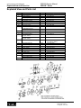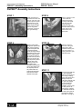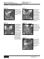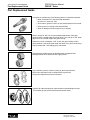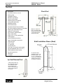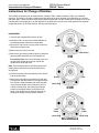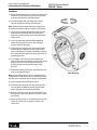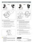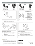
1
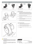
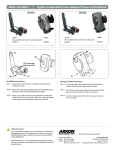
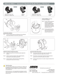
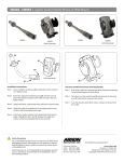
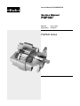
Service Manual HY09-SM020/US
Service Manual
PGP020™
Effective:
Supersedes:
July 1, 2006
All Others
PGP020 Series
The Parker Hannifin
Gear Pump Division
Assures:
! Consistent quality
! Technical innovation
! Premier customer service
Worldwide Sales
and Service
Parker operates sales and service
centers in major industrial areas
worldwide. Call 1-800-C-PARKER for
more information, or for a synopsis
of the Gear Pump Division, contact a
Parker representative.
The Gear Pump Division’s ability to engineer
specialty products for unique applications has
kept us at the forefront of technology, and
ensured our position as the industry leader.
Our success has come from providing a
quality product with excellent sales and
service support.
We manufacture
hydraulic components
for a wide range of
industries including:
• Construction
• Refuse/dump truck
• Material handling
• Forestry
• Agriculture
• Industrial
WARNING
FAILURE OR IMPROPER SELECTION OR IMPROPER USE OF THE PRODUCTS AND/OR SYSTEMS DESCRIBED HEREIN OR RELATED ITEMS CAN CAUSE DEATH, PERSONAL
INJURY AND PROPERTY DAMAGE.
This document and other information from Parker Hannifin Corporation, its subsidiaries and authorized distributors provide product and/or system options for further investigation by users
having technical expertise. It is important that you analyze all aspects of your application and review the information concerning the product or system in the current product catalog. Due
to the variety of operating conditions and applications for these products or systems, the user, through its own analysis and testing, is solely responsible for making the final selection of
the products and systems and assuring that all performance, safety and warning requirements of the application are met.
The products described herein, including without limitation, product features, specifications, designs, availability and pricing, are subject to change by Parker Hannifin Corporation and its
subsidiaries at any time without notice.
Offer of Sale
The items described in this document are hereby offered for sale by Parker Hannifin Corporation, its subsidiaries or its authorized distributors. This offer and its acceptance are governed
by the provisions stated in the “Offer of Sale”.
© Copyright 2006, Parker Hannifin Corporation, All Rights Reserved.
2
Parker Hannifin Corporation
Gear Pump Division
Youngstown, Ohio USA
Service Manual HY09-SM020/US
Contents
PGP020 Service Manual
PGP020™ Series
Index
General Instructions ............................................... 4
Cleanliness ............................................................. 4
Cautions ................................................................. 4
Exploded View and Parts List ................................. 5
PGP020™ Disassembly Instructions ...................... 6
PGP020™ Assembly Instructions ........................... 9
Part Replacement Guide ...................................... 12
Tool List ................................................................ 13
Lubrication and Oil Recommendations ................. 14
Recommended Start-up Procedure
for New or Rebuilt Pump or Motor ......................... 16
Test Procedure Recommended ............................ 17
Instructions for Change of Rotation ...................... 18
Offer of Sale ......................................................... 22
3
Parker Hannifin Corporation
Gear Pump Division
Youngstown, Ohio USA
Service Manual HY09-SM020/US
General Instructions/Cleanliness/Cautions
PGP020 Service Manual
PGP020™ Series
Pump Service Instructions
General Instructions
Cautions
These service instructions will:
1) Parker replacement parts are made to original
equipment standards. For assured quality of
material and workmanship and for compatibility
in assembly, USE ONLY GENUINE Parker
REPLACEMENT PARTS.
• familiarize you with the PGP020 series roller
bearing pump, its component parts and their
relative position;
• show the proper methods for disassembly
and assembly;
2) If it becomes necessary to pry apart castings,
use extreme caution not to mar or damage the
machined surfaces. Excessive force while
prying can result in misalignment and seriously
damage parts.
• advise appropriate care and use of this
hydraulic pump.
Following these instructions can prolong the life of your
pump, and help achieve optimal performance.
3) If component assembly is difficult, do not force
items and never employ an iron hammer. For a
complete list of recommended tools, see Page 11.
We recommend you read this entire set of instructions
before attempting any repair.
To ensure damage did not occur during shipment,
check all replacement parts closely before installation.
4) Gears are closely matched, therefore, they must be
kept together as a set when removed from the unit.
Handle with care to avoid damage to the journals,
faces and teeth.
Cleanliness
5) Never hammer roller bearings into bores. Use only
an arbor press or other suitable tool.
Dirt is the enemy of any hydraulic system, so keeping
equipment clean is a crucial maintenance requirement.
6) It is important to airblast all parts and wipe them
with a clean, lint-free cloth before assembly.
MAKE SURE YOU DISASSEMBLE AND
ASSEMBLE YOUR HYDRAULIC EQUIPMENT
IN A CLEAN AREA.
TO PREVENT PERSONAL INJURY, SAFETY
GLASSES AND STEEL TOE SHOES SHOULD
BE WORN.
4
Parker Hannifin Corporation
Gear Pump Division
Youngstown, Ohio USA
Service Manual HY09-SM020/US
Exploded View and Parts List
PGP020 Service Manual
PGP020™ Series
Exploded View and Parts List
Item No. Description
1
2
3
4
5
6
6A
7
8
9
10
11
12
13
14
16
17
18
19
20
21
22
Required
Snap Ring
Outboard Bearing
Outboard Spacer
Lip Seal (pump)
Seal Retainer (motor)
Lip Seal (motor)
Shaft End Cover
Drain Plug (motor)
Check Assemblies for Motors
& Bi-Rotational Pumps
Plugs (pumps only)
Ring Seals (per gear section)
Roller Bearings (per gear section)
Thrust plates (motor)
(per gear section)
Thrust plates (pump)
(per gear section)
Pocket Seals (per gear section)
1 strip
Drive Shaft Gear Set
Gasket Seals (per gear section)
Gear Housing
Bearing Carrier
Connecting Shaft
Gear Set
Port End Cover
Washers
Cap Screws (single units)
Studs (multiple units)
Nuts (multiple units)
1 Set
2
1
set
1
4
4
4
4
5
Ten Digit No. (TDN)
1
1
1
1
1
1
1
1
2
391-2686-063
391-0381-040
391-3383-069
391-2883-058
391-3381-040
391-2883-119
308-50XX-XXX
391-2282-XXX
391-3681-001
1
2
4
2
391-2286-004
391-2585-006
391-0381-906
391-2185-913
2
391-2185-913
391-2882-022 (Viton)
391-2882-051 (Buna)
312-29XX-XXX
391-2884-019
308-8XXX-XXX
308-7XXX-XXX
312-1133-001
312-28XX-XXX
308-3XXX-XXX
391-3782-146
391-1401-XXX
391-1425-XXX
391-1451-115
Parker Hannifin Corporation
Gear Pump Division
Youngstown, Ohio USA
Service Manual HY09-SM020/US
PGP020™ Disassembly Instructions
PGP020 Service Manual
PGP020™ Series
PGP020™ Disassembly Instructions
STEP 1
STEP 2
Place the pump in a
vise with the drive shaft
pointing down. Clamp
unit on the sides of the
mounting flange. Do not
clamp on the pilot
diameter as it may
damage the sealing
surface.
Mark each casting in
the assembly with
machinist ink or a prick
punch to orient the
castings, so that the
unit can be
reassembled later in
the proper position.
STEP 3
STEP 4.1
Loosen and remove the
four, cap screws and
washers with a 13/16”
socket and wrench.
Remove the port end
cover subassembly
using steps 4.1 - 4.3:
4.1 Place the point of a
large, screwdriver or a
chisel on the parting
line between the port
end cover casting and
the gear housing
casting. Gently tap until
a slight separation
between the castings is
detected.
STEP 4.2
STEP 4.3
4.2 Place two, large,
flat-bladed screwdrivers
into the separation
notches and pry up the
port end cover until
loose. BE CAREFUL
not to nick, mar or
scratch the machined
casting faces.
4.3 Lift off the port end
cover subassembly.
6
Parker Hannifin Corporation
Gear Pump Division
Youngstown, Ohio USA
Service Manual HY09-SM020/US
PGP020™ Disassembly Instructions
PGP020 Service Manual
PGP020™ Series
PGP020™ Disassembly Instructions
STEP 5.1
STEP 5.2
Remove the gear
housing subassembly
using steps 5.1 - 5.3:
5.2 Lift off the gear
housing subassembly.
5.1 Place the two,
large, flat-bladed
screwdrivers into the
separation notches
and pry up the gear
housing until loose. BE
CAREFUL not to nick,
mar or scratch the
machined casting
faces.
STEP 5.3
STEP 6
5.3 Remove the thrust
plate from the housing.
It may be necessary to
gently tap the thrust
plate with the handle of
a hammer or
screwdriver. Be careful
not to bend or score the
thrust plate. Remove
and discard the six,
small, rubber pocket
seals from the thrust
plate.
Remove and discard
the rubber section seals
from the top and bottom
gear housing faces.
STEP 7
STEP 8
Wipe the gear face
surface dry with a
clean, lint-free cloth.
Mark the teeth of the
drive and driven gears
(the gear set) at their
mesh point with
machinist ink or quickdry marker. This is to
index the gear set for
proper orientation
during reassembly.
Remove the idler gear
and the gear shaft.
Keep them together as
they are a matched set.
Handle with care to
avoid damage to the
journals, faces and
teeth.
7
Parker Hannifin Corporation
Gear Pump Division
Youngstown, Ohio USA
Service Manual HY09-SM020/US
PGP020™ Disassembly Instructions
PGP020 Service Manual
PGP020™ Series
PGP020™ Disassembly Instructions
STEP 9
STEP 10
Gently lift off the thrust
plate. Be careful not to
bend or score the plate
and mating surface of
the casting. Remove
and discard the six,
rubber pocket seals
from the back of the
thrust plate.
Remove lip seal. Place a
lip seal removal tool (see
Tool List P11) or a
screwdriver tip against
the inside of the lip seal
and tap the screwdriver
handle with a hammer.
Be careful not to damage
the roller bearing or the
ring seal with screwdriver
tip. Note: If bearings are
to be removed from the
casting, then step can be
performed after Step 12.
STEP 11
STEP 12
Use a bearing puller to
remove the roller
bearings. Note: This
step is optional
depending on the
condition of the
bearings.
Remove the bronze ring
seal from the gear shaft
bearing bore in the
shaft end cover and the
port end cover castings.
STEP 13
Remove the checks
from the shaft end
cover casting with the
check tool (see Tool List
on Page 11).
CAUTION: Failure to follow
the recommended assembly
instructions can result in
poor performance or failure
of the product. Product
should be thoroughly tested
to ensure proper operation
before the unit is put back
into service.
8
Parker Hannifin Corporation
Gear Pump Division
Youngstown, Ohio USA
Service Manual HY09-SM020/US
PGP020™ Assembly Instructions
PGP020 Service Manual
PGP020™ Series
PGP020™ Assembly Instructions
STEP 1
STEP 2
Stone all machined
casting surfaces with a
medium-grit
carborundum stone. If
the bearings were
removed, deburr the
bearing bore using a
deburring tool. Rinse all
parts in a solvent fluid.
Air blast all parts and
wipe them with a clean,
lint-free cloth before
starting the assembly.
Coat the outside
diameter of the lip seal
with Permatex Aviation
Form-A-Gasket No.3
Non-Hardening Sealant
or equivalent. Be
careful not to get
Permatex on the inner
lip of the seal as it will
cause a lip seal leak.
STEP 3
STEP 4
Place the shaft end cover
on an arbor press with
the pilot facing up. Place
lip seal with the shoulder
of the seal up, at the top
of the seal bore. Press
the lip seal into the shaft
end cover with a lip seal
installation bar (see Tool
List on Page 11). The
seal should be pressed
in so it is flush with the
recessed face in the
shaft end cover casting.
Apply Loctite® No.262
to the threaded check
holes in the shaft end
casting. Install the
checks in the shaft end
cover using the check
tool (see Tool List on
Page 11). The checks
must bottom out in
the casting.
STEP 5
STEP 6
Peen over the check
holes in the shaft end
cover with a 1½” steel
ball and a hammer.
This will insure the
checks do not back out
of the check holes
during operation.
If the ring seals were
removed from the shaft
end cover or the port
end cover, they should
be replaced at this time.
Place the ring seals in
the bottom of the drive
gear bearing bores. Be
sure that the flat side of
the ring seal is against
the mating surface in the
casting. Ring seals are
placed behind the drive
gear bearings only.
9
Parker Hannifin Corporation
Gear Pump Division
Youngstown, Ohio USA
PGP020 Service Manual
PGP020™ Series
Service Manual HY09-SM020/US
PGP020™ Assembly Instructions
PGP020™ Assembly Instructions
STEP 7
STEP 8
Install the bearings in
the shaft end cover and
the port end cover. Use
an arbor press to press
the bearings into the
bottom of the bearing
bores. Check to make
sure the ring seals
move freely under the
drive gear bearings.
Grip the shaft end cover
in a vise with the
mounting face down.
Cut two, pocket seals
7/32” long from the
pocket seal strip.
Grease the seals well
and insert them into the
center slots on the
reverse side of the
thrust plate.
STEP 9
STEP 10
With the pocket seals
facing down, place thrust
plate over the bearings.
Tap the thrust plate with
a soft-faced hammer
around the edge until the
thrust plate is about 1/32”
from the casting surface.
Do not tap the center of
the plate. Cut four pocket
seals 1/4” long from the
seal strip. Push a pocket
seal into each of the
remaining slots in the
thrust plate until it
touches the bearing wall.
Use a razor blade to trim
the exposed portion of
the pocket seals. The
pocket seals should be
flush with the outside
diameter of the plate.
Insert the external
drive end of the gear
shaft into the shaft
installation sleeve (see
Tool List on Page 11 ).
Lightly grease the gear
shaft and sleeve.
STEP 11
Insert the gear shaft with
the shaft installation
sleeve into the shaft end
cover using a twisting
motion. Be careful not to
damage the lip seal.
Push down carefully until
the gear rests against
the thrust plate face.
Remove the shaft
installation sleeve. Insert
the idler gear into its
bearing bore, matching
the orientation marks on
the teeth of the gear set
as previously marked
(see Step 7 on Page 5).
10
Parker Hannifin Corporation
Gear Pump Division
Youngstown, Ohio USA
PGP020 Service Manual
PGP020™ Series
Service Manual HY09-SM020/US
PGP020™ Assembly Instructions
PGP020™ Assembly Instructions
STEP 12
STEP 13
Apply a light coating of
grease to the new
section seals and place
them into the machined
grooves on both sides
of the gear housing.
Check the section seals
for proper fit.
Locate the orientation
mark on the gear
housing and line it up
with the mark on the
shaft end cover. Slide the
gear housing over gear
set. Make sure the gear
housing rests tightly
against shaft end cover.
Be careful not to pinch
the section seal. Squirt
clean, hydraulic oil over
the gear shaft and the
idler gear to provide initial
lubrication when the
pump is started.
STEP 14
STEP 15
Thread the four, cap
screws with the
washers into the shaft
end cover and tighten
them in a cross-corner
pattern. Rotate the gear
shaft of the pump with a
6” wrench to make
certain there is no
binding in the pump.
Insert the pocket seals
into the thrust plate and
install onto the port end
cover following the
previous instructions in
steps 8 & 9. Then place
port end cover over the
gear journals. The
orientation mark on port
end cover must line up
with the mark on the gear
housing. Also, be sure
bearing bore holding the
ring seal goes over the
drive gear journal. Apply
pressure to the casting
with your hand or tap
lightly with a soft-faced
hammer until the port
end cover rests tightly
against the gear housing.
STEP 16
After the cap screws
are tightened, make
certain there is no
internal binding of the
gear set by rotating
the gear shaft, then
tighten the cap screws
in a cross-corner
pattern to a final
torque of 2400 in. lbs.
(200 ft. lbs.).
11
Parker Hannifin Corporation
Gear Pump Division
Youngstown, Ohio USA
PGP020 Service Manual
PGP020™ Series
Service Manual HY09-SM020/US
Part Replacement Guide
Part Replacement Guide
If the gear set contains any of the following defects, it should be replaced:
• Wear on the hubs or in the seal areas detectable
by touch or in excess of .002”.
• Score marks, grooves or burrs on the outside diameter of the teeth.
• Nicks, grooves or fretting of the teeth surfaces.
• Wear or damage to the drive spline, key or keyway.
Wear in excess of .005” cut-out necessitates replacement of the gear
housing. Place a straight-edge across the bore. If you can slip a .005” feeler
gage in the cut-out area, replace the gear housing.
Where the cut-out is moderate, .005” or less, the gear housing is still in
good condition. If the housing has equal size ports or no ports, the housing
may be rotated 180°, exchanging ports, and reused.
If the gears are replaced, then the bearings must be replaced also.
Bearings should fit into the bores with a light press fit.
Any scratches, grooves, erosion or pitting on the thrust plate face,
which is the area that comes in contact with the gear faces,
requires the replacement of the thrust plates.
Replace all rubber and polymer seals whenever reassembling the pump.
This includes lip seal, pocket seal strips and section seals.
12
Parker Hannifin Corporation
Gear Pump Division
Youngstown, Ohio USA
Service Manual HY09-SM020/US
Tool List
PGP020 Service Manual
PGP020™ Series
Tool List
• Arbor press
• Permanent marker or an awl
• Bearing puller
(Owatonna Tool Co.
MD-956 or equivalent)
• Clean, lint-free cloths
• Deburring tool (a file with the
cutting teeth ground off)
• Machinist hammer
• Soft-faced hammer
• Permatex Aviation Form-A-Gasket
No.3 Non-hardening Sealant or equivalent
• Medium-grit carborundum stone
• Hydraulic oil and grease
• Prick punch or machinists ink
• Sharp, razor blade
• Scale (1/32” or 1/64” graduations)
• Feeler gauges
• Small, flat-head screwdriver
• Large, flat-headed screwdrivers
• Torque wrench
• 13/16” socket
• 1½” steel ball
• Loctite® No.262
• Vise with a 6” minimum open spread
• Lip seal installation bar (1 3/4” X 2”)
• Shaft installation sleeve (steel)
• Lip seal removal tool
• Check tool
• 6” wrench
Lip Seal Removal Tool
Check Tool
Make the check tool
from a 4” length of 3/8”
diameter drill rod and a
3 1/2” length of 3/16”
diameter drill rod.
Shaft Installation Sleeve (Steel)
To make the shaft
installation sleeve, use
bar stock that is 1 1/8”
or 1 1/4” in diameter by
4 5/8” long. All external
surfaces must be free
of scratches and burrs.
A seal removal tool can
be made easily from an
old screwdriver. Heat
the tip and bend as
shown. Grind off the tip
to fit the notch behind
the lip seal.
13
Parker Hannifin Corporation
Gear Pump Division
Youngstown, Ohio USA
PGP020 Service Manual
PGP020™ Series
Service Manual HY09-SM020/US
Lubrication/Oil Recommendations
Lubrication and Oil Recommendations
All parts, with the exception of the outboard bearing, are lubricated by the hydraulic oil in the circuit. Particular
attention must be paid to keep the oil in the system clean. Whenever there is a pump or motor failure and there is
reason to suspect that metal particles may be in the system, the oil must be drained, the entire system flushed
clean and any filter screens thoroughly cleaned or replaced. New oil should be supplied for the entire system. Oil
suitable and recommended for use in circuits involving Commercial Hydraulics’ pumps and motors should meet
the following specifications:
Viscosity: • 50 SSU minimum @ operating temperature
7500 SSU maximum @ starting temperature
• 150 to 225 SSU @ 100º F (37.8º C) (generally)
44 to 48 SSU @ 210º F (98.9º C) (generally)
Approximate SSU at . . .
Oil Grade
SAE 10
SAE 20
100 F (37. 8° C)
150
330
210° F (98.9° C)
43
51
Viscosity Index: 90 minimum
Aniline Point: 175 minimum
Recommended Additives: Foam Depressant
Rust and Oxidation Inhibitors
Other Desirable Characteristics: • Stability of physical and chemical characteristics.
• High demulsibility (low emulsibility) for separation
of water, air and contaminants.
• Resistant to the formation of gums, sludges, acids, tars and varnishes.
• High lubricity and film strength.
General Recommendations:
A good-quality, hydraulic oil conforming to the characteristics listed above is essential to the satisfactory
performance and long life of any hydraulic system.
Oil should be changed on a regular schedule in accordance with the equipment manufacturer’s
recommendations, and the system should be periodically flushed.
Oil temperature in reservoir must not exceed 200º F (93.3º C) with a maximum temperature of 180º F (82.2º C)
recommended. Higher temperatures will result in rapid oil deterioration.
Reservoir capacity should equal in gallons the pump output in gpm or the total gpm of all pumps where there is
more than one in the system.
Normal Temperatures:
0º F (-18º C) to 100º F (37.8º C) Ambient
100º F (37.8º C) to 180º F (82.2º C) System
Be sure your oil is suitable for the temperatures you expect to encounter.
Cold Weather Operation:
Oils for use in cold weather should have a viscosity that does not exceed 7500 SSU at the minimum start-up
temperature. A pour point of at least 20º F below start-up temperature is recommended. Start-up procedures
should allow for a gradual warm-up until the oil reaches a reasonably fluid state.
14
Parker Hannifin Corporation
Gear Pump Division
Youngstown, Ohio USA
Service Manual HY09-SM020/US
Lubrication/Oil Recommendations
PGP020 Service Manual
PGP020™ Series
Lubrication and Oil Recommendations
The Use of Other Oils:
• Diesel Fuel or Kerosene (Coal Oil): These are sometimes used as dilutants for cold weather operations but
are not recommended as they are not sufficiently refined products.
• Fire-Resistant Fluids: Of the several different types, only the inverted emulsion types may be used without
switching to a special seal, packing, gasket, hose, etc., compositions. Their use may substantially reduce
pump life. Experience indicates that the use of fire-resistant fluids can be disastrous unless certain
precautions are followed. DO NOT USE ANY FIRE RESISTANT FLUIDS OR NON-PETROLEUM OILS
WITHOUT CONSULTING OUR PRODUCT SUPPORT DEPARTMENT.
• These suggestions are intended as a guide only. OBTAIN YOUR FINAL OIL RECOMMENDATIONS FROM
YOUR OIL SUPPLIER.
15
Parker Hannifin Corporation
Gear Pump Division
Youngstown, Ohio USA
Service Manual HY09-SM020/US
Reccomended Start-up Procedure
PGP020 Service Manual
PGP020™ Series
Recommended Start-up Procedure
for New or Rebuilt Pump or Motor
Before installing a new or a rebuilt pump or motor, back out the main relief valve until the spring tension on the
adjusting screw is relaxed. This will avoid the possibility of immediate damage to the replacement unit in the event
that the relief valve setting had been increased beyond the recommended operating pressure prior to removing
the old unit.
Before connecting any lines to the pump or to the motor, fill all ports with clean oil to provide initial lubrication. This
is particularly important when the unit is located above the oil reservoir.
After connecting the lines and mounting the replacement unit, operate the pump or the motor for at least two
minutes at zero pressure at the lowest possible rpm. During this break-in period, the unit should run free and not
develop an excessive amount of heat. If the unit operates properly, the speed and the pressure can then be
increased to the normal operating settings.
Reset the main relief valve to its proper setting while the pump is running at the maximum operating engine
(motor) speed for the vehicle.
ALWAYS USE AN ACCURATE GAGE WHEN ADJUSTING THE
RELIEF VALVE PRESSURE SETTING.
16
Parker Hannifin Corporation
Gear Pump Division
Youngstown, Ohio USA
PGP020 Service Manual
PGP020™ Series
Service Manual HY09-SM020/US
Test Procedure Recommended
Test Procedure Recommended
Be sure there is an adequate supply of oil for the
pump; at least one gallon of oil for each gpm of pump
capacity.
have to be disassembled and be rebuilt, taking extra
care to remove burrs and to assure freedom from
binding.
If one section of a tandem pump is being tested, make
sure all other sections which are not being tested, are
adequately supplied with oil. If any of the other sections
run dry or if plugs are left in ports, serious and
permanent damage will result.
Gradually increase the pressure on a pump until the
desired test pressure has been reached. This should
take about five minutes.
Delivery should run close to the rated, catalog
performance figures which are averaged from the
testing of several pumps. A 5% lower reading may be
used as a rated minimum, if new or relatively new parts
have been used. When rebuilding the pump, reuse only
those parts which appear to be in satisfactory
condition. A 10% or 15% lower reading is permitted for
the rebuilt pump, depending upon the performance
expected from the equipment. Your individual
experience is the best guide.
The oil should be a good-quality, hydraulic oil rated at
150 SSU at 100º F with the oil temperature held at
120º F plus or minus 5º F. (Test procedures are
described in detail in SAE handbooks; see Hydraulic
Power Pump Test Procedure SAE J745c.)
The inlet line must be an adequate size with no more
than 5” mercury vacuum adjacent to the pump inlet. As
a rule, the inlet line must provide an inlet flow velocity
that is not in excess of 8 feet per second.
Many repairmen measure the output at the normal
operating speed, at zero pressure, then at 1000 psi (or
the operating pressure of the equipment), and allow a
volume decrease approximating the listing below. The
table listing shows the drop off in flow that can be
expected at various operating pressures for a pump
rebuilt with used parts.
Hot oil drawn into a cold pump could cause it to seize.
Switching the pump on and off in short bursts could
help prevent seizure.
Operate the pump at least two minutes at zero
pressure and at moderate speed (not over 1500 rpm).
PGP020 pumps are generally tested to 2000 psi.
If pump becomes hot to touch, it is binding and could
seize. This rarely occurs, but if it does, the pump will
GPM Delivery
at 1800rpm
GPM Drop Off At...
100 psi
1000 psi/70 bar
1500 psi/105 bar
2000 psi/140 bar
2500 psi/175 bar
5 - 14
2 to 3
21/2 - 31/2
3 to 4
31/2 - 41/2
15 - 25
21/2 to 31/2
3-4
31/2 to 5
4 - 51/2
26 - 50
3 to 4
4-5
4 to 6
41/2 - 61/2
At test speeds other than 1800 rpm, gpm delivery will
vary almost proportionately, but the same (drop-off)
figures should be used.
Since it is rarely feasible to test motors on
dynamometers, the practical procedure is to test them
as pumps, running complete testing procedures in
each direction.
Be sure to run the pump in the direction for which it
was designed and built. Driving the pump in the wrong
direction will build up pressure behind the lip seal,
causing damage to the pump and necessitating its
replacement.
After completing the testing procedures, the pump is
ready for installation and immediate duty operation on
equipment. It must be reinforced that to prevent
seizure, hot oil must not be drawn into a cold pump.
17
Parker Hannifin Corporation
Gear Pump Division
Youngstown, Ohio USA
Service Manual HY09-SM020/US
Instructions for Change of Rotation
PGP020 Service Manual
PGP020™ Series
Instructions for Change of Rotation
The PGP020 series pump can be assembled for clockwise (CW), counterclockwise (CCW), or bi-rotational
operation. The direction of rotation is determined by looking at the pump with the drive shaft facing you and the
idler gear down. If the pump has unequal porting and the larger port is on the left side, then the pump is set up for
CW operation. If the larger port is on the right side of the pump, then it is set up for CCW operation. Bi-rotational
pumps that can be run in either direction, will have equal size ports.
DISASSEMBLY
1 If the unit has a keyed shaft, remove the key.
2) Clamp the unit in a vise on the outside diameter of
the mounting flange with the drive shaft down.
3) Remove the cap screws on single units or hex nuts
and studs on multiple units.
Inlet
Outlet
4) Remove the port (rear) end cover.
Check Plug
5) Remove the gear housing and the gear set. Keep the
gears together because they are a matched set.
CW
For multiple units: Remove the bearing carrier and
the next gear housing and gear set until all that
remains is the shaft end cover.
Note: Care should be taken to avoid losing the small,
rubber pocket seals fitted in the thrust plate pocket
seal grooves.
6) Lift the thrust plate off of the shaft end cover. Do not
lose the pocket seals.
Outlet
7) Remove the check plug in the shaft end cover with
a screwdriver and then install it in the opposite drain
hole. Screw in tightly and stake the check plug with
a punch at both edges of the screwdriver slot. For
a single-rotation pump, the check plug is always
located on the high pressure (outlet) side of the
pump. If the shaft end cover has two check plugs,
the pump is already set-up for double rotation.
Inlet
Check Plug
CCW
Inlet/
Outlet
Inlet/
Outlet
Check Plug
Check Plug
Bi-rotational
18
Parker Hannifin Corporation
Gear Pump Division
Youngstown, Ohio USA
Service Manual HY09-SM020/US
Instructions for Change of Rotation
PGP020 Service Manual
PGP020™ Series
ASSEMBLY
1) Before assembling the unit, stone off the machined
surfaces. This will remove any nicks or burrs that
may have resulted from the disassembly.
2) Air blast all parts and wipe them with a clean,
lint-free cloth before starting the assembly.
Note: PGP020 series thrust plates are designed for
bi-rotational operation and do not have to be rotated.
3) Place one thrust plate with pocket seals over the
shaft end cover bearings. Be sure the pocket
seals are properly fitted in the thrust plate pocket
seal grooves.
4) Insert the gear shaft with the shaft installation
sleeve into the shaft end cover with a twisting
motion. Insert the idler gear.
5) Rotate the gear housing 180° and carefully slide
over the gear set. Make sure both section seals
stay in the seal grooves during assembly. Keep the
drive gear and idler gear in the same gear bore as
previously marked.
6) For multiple units: Place the thrust plates with
pocket seals over the bearings on both sides of the
bearing carrier. Be sure the pocket seals are
properly fitted in the thrust plate pocket seal
grooves.
7) Rotate the bearing carrier 180° and install over the
gear set and gear housing.
Gear Housing
Note: If the bearing carrier has an L-shaped porting
configuration, it cannot be used. A new bearing carrier
will have to be machined with the proper configuration.
8) Insert the gears into the bearing carrier.
9) Rotate the gear housing 180° and carefully slide
over the gear set. Make sure both section seals
stay in the seal grooves during assembly.
10) Place the port end cover with the thrust plate over
the gear set. If the port end cover is ported, it must
be inverted.
11) Insert the cap screws or the studs into the unit and
torque in a cross-corner pattern to 2400 in. lbs
(200 ft. lbs).
19
Parker Hannifin Corporation
Gear Pump Division
Youngstown, Ohio USA
Notes
20
Parker Hannifin Corporation
Gear Pump Division
Youngstown, Ohio USA
Notes
21
Parker Hannifin Corporation
Gear Pump Division
Youngstown, Ohio USA
Offer of Sale
The items described in this document are hereby offered for sale at prices to be established by Parker Hannifin Corporation, its subsidiaries and its
authorized distributors. This offer and its acceptance by any customer (“Buyer”) shall be governed by all of the following Terms and Conditions. Buyer’s order
for any item described in its document, when communicated to Parker Hannifin Corporation, its subsidiary or an authorized distributor (“Seller”) verbally or in
writing, shall constitute acceptance of this offer.
1. Terms and Conditions of Sale: All descriptions, quotations, proposals,
offers, acknowledgments, acceptances and sales of Seller’s products are
subject to and shall be governed exclusively by the terms and conditions
stated herein. Buyer’s acceptance of any offer to sell is limited to these terms
and conditions. Any terms or conditions in addition to, or inconsistent with
those stated herein, proposed by Buyer in any acceptance of an offer by
Seller, are hereby objected to. No such additional, different or inconsistent
terms and conditions shall become part of the contract between Buyer and
Seller unless expressly accepted in writing by Seller. Seller’s acceptance of
any offer to purchase by Buyer is expressly conditional upon Buyer’s assent
to all the terms and conditions stated herein, including any terms in addition
to, or inconsistent with those contained in Buyer’s offer. Acceptance of
Seller’s products shall in all events constitute such assent.
8. Buyer’s Property: Any designs, tools, patterns, materials, drawings,
confidential information or equipment furnished by Buyer or any other items
which become Buyer’s property, may be considered obsolete and may be
destroyed by Seller after two (2) consecutive years have elapsed without
Buyer placing an order for the items which are manufactured using such
property. Seller shall not be responsible for any loss or damage to such
property while it is in Seller’s possession or control.
9. Taxes: Unless otherwise indicated on the face hereof, all prices and
charges are exclusive of excise, sales, use, property, occupational or like
taxes which may be imposed by any taxing authority upon the manufacture,
sale or delivery of the items sold hereunder. If any such taxes must be paid
by Seller or if Seller is liable for the collection of such tax, the amount thereof
shall be in addition to the amounts for the items sold. Buyer agrees to pay all
such taxes or to reimburse Seller therefore upon receipt of its invoice. If
Buyer claims exemption from any sales, use or other tax imposed by any
taxing authority, Buyer shall save Seller harmless from and against any such
tax, together with any interest or penalties thereon which may be assessed if
the items are held to be taxable.
2. Payment: Payment shall be made by Buyer net 30 days from the date
of delivery of the items purchased hereunder. Any claims by Buyer for
omissions or shortages in a shipment shall be waived unless Seller receives
notice thereof within 30 days after Buyer’s receipt of the shipment.
3. Delivery: Unless otherwise provided on the face hereof, delivery shall be
made F.O.B. Seller’s plant. Regardless of the method of delivery, however,
risk of loss shall pass to Buyer upon Seller’s delivery to a carrier. Any
delivery dates shown are approximate only and Seller shall have no liability
for any delays in delivery.
4. Warranty: Seller warrants that the item sold hereunder shall be free from
defects in material or workmanship for a period of 547 days from the date of
shipment to Buyer, or 3,000 hours of use, whichever expires first. THIS
WARRANTY COMPRISES THE SOLE AND ENTIRE WARRANTY
PERTAINING TO ITEMS PROVIDED HEREUNDER. SELLER MAKES NO
OTHER WARRANTY, GUARANTEE, OR REPRESENTATION OF ANY
KIND WHATSOEVER. ALL OTHER WARRANTIES, INCLUDING BUT NOT
LIMITED TO, MERCHANTABILITY AND FITNESS FOR PURPOSE,
WHETHER EXPRESS, IMPLIED, OR ARISING BY OPERATION OF LAW,
TRADE USAGE, OR COURSE OF DEALING ARE HEREBY DISCLAIMED.
NOTWITHSTANDING THE FOREGOING, THERE ARE NO WARRANTIES
WHATSOEVER ON ITEMS BUILT OR ACQUIRED WHOLLY OR PARTIALLY, TO BUYERS DESIGNS OR SPECIFICATIONS.
10. Indemnity For Infringement of Intellectual Property Rights: Seller
shall have no liability for infringement of any patents, trademarks, copyrights,
trade dress, trade secrets or similar rights except as provided in this Part 10.
Seller will defend and indemnify Buyer against allegations of infringement of
U.S. patents, U.S. trademarks, copyrights, trade dress and trade secrets
(hereinafter ‘Intellectual Property Rights’). Seller will defend at its expense
and will pay the cost of any settlement or damages awarded in an action
brought against Buyer based on an allegation that an item sold pursuant to
this contract infringes the Intellectual Property Rights of a third party. Seller’s
obligation to defend and indemnify Buyer is contingent on Buyer notifying
Seller within ten (10) days after Buyer becomes aware of such allegations of
infringement, and Seller having sole control over the defense of any
allegations or actions including all negotiations for settlement or compromise.
If an item sold hereunder is subject to a claim that it infringes the Intellectual
Property Rights of a third party, Seller may, at its sole expense and option,
procure for Buyer the right to continue using said item, replace or modify said
time so as to make it noninfringing, or offer to accept return of said item and
return the purchase price less a reasonable allowance for depreciation.
Notwithstanding the foregoing Seller shall have no liability for claims of
infringement based on information provided by Buyer, or directed to items
delivered hereunder for which the designs are specified in whole or part by
Buyer, or infringements resulting from the modification, combination or use in
a system of any item sold hereunder. The foregoing provisions of this Part 10
shall constitute Seller’s sole and exclusive liability and Buyer’s sole and
exclusive remedy for infringement of Intellectual Property Rights.
5. Limitation of Remedy: SELLER’S LIABILITY ARISING FROM OR IN
ANY WAY CONNECTED WITH THE ITEMS SOLD OR THIS CONTRACT
SHALL BE LIMITED EXCLUSIVELY TO REPAIR OR REPLACEMENT OF
THE ITEMS SOLD OR REFUND OF THE PURCHASE PRICE PAID BY
BUYER, AT SELLER’S SOLE OPTION IN NO EVENT SHALL SELLER BE
LIABLE FOR ANY INCIDENTAL OR SEQUENTIAL OR SPECIAL
DAMAGES OF ANY KIND OR NATURE WHATSOEVER, INCLUDING BUT
NOT LIMITED TO LOST PROFITS ARISING FROM OR IN ANY WAY
CONNECTED WITH THIS AGREEMENT OR ITEM SOLD HEREUNDER,
WHETHER ALLEGED TO ARISE FROM BREACH OF CONTRACT,
EXPRESS OR IMPLIED WARRANTY, OR IN TORT, INCLUDING WITHOUT
LIMITATION, NEGLIGENCE, FAILURE TO WARN OR STRICT LIABILITY.
If a claim is based on information provided by Buyer or if the design for an
item delivered hereunder is specified in whole or in part by Buyer, Buyer shall
defend and indemnify Seller for all costs, expenses or judgments resulting
from any claim that such item infringes any patent, trademark, copyright,
trade dress, trade secret or any similar right.
6. Changes, Reschedules and Cancellations: Buyer may request to modify
the designs or specifications for the items sold hereunder as well as the
quantities and delivery dates thereof, or may request to cancel all or part of
this order, however, no such requested modification or cancellation shall
become part of the contract between Buyer and Seller unless accepted by
Seller in a written amendment to this Agreement. Acceptance of any such
requested modification or cancellation shall be at Seller’s discretion, and
shall be upon such terms and conditions as Seller may require.
11. Force Majeure: Seller does not assume the risk of and shall not be
liable for delay or failure to perform any of Seller’s obligations by reason of
circumstances beyond the reasonable control of Seller (hereinafter ‘Events
of Force Majeure’). Events of Force Majeure shall include without limitation,
accidents, acts of God, strikes or labor disputes, acts, laws, rules or
regulations of any government or government agency, fires, floods, delays
or failures in delivery of carriers or suppliers, shortages of materials and
any other cause beyond Seller’s control.
7. Special Tooling: A tooling charge may be imposed for any special tooling,
including without limitation, dies, fixtures, molds and patterns, acquired to
manufacture items sold pursuant to this contract. Such special tooling shall
be and remain Seller’s property notwithstanding payment of any charges by
Buyer. In no event will Buyer acquire any interest in apparatus belonging to
Seller which is utilized in the manufacture of the items sold hereunder, even if
such apparatus has been specially converted or adapted for such manufacture and notwithstanding any charges paid by Buyer. Unless otherwise
agreed, Seller shall have the right to alter, discard or otherwise dispose of
any special tooling or other property in its sole discretion at any time.
12. Entire Agreement/Governing Law: The terms and conditions set forth
herein, together with any amendments, modifications and any different terms
or conditions expressly accepted by Seller in writing, shall constitute the
entire Agreement concerning the items sold, and there are no oral or other
representations or agreements which pertain thereto. This Agreement shall
be governed in all respects by the law of the State of Ohio. No actions arising
out of the sale of the items sold hereunder or this Agreement may be brought
by either party more than two (2) years after the cause of action accrues.
22
Parker Hannifin Corporation
Gear Pump Division
Youngstown, Ohio USA
Parker Hannifin Corporation
6035 Parkland Blvd.
Cleveland, Ohio 44124-4141
Telephone: (216) 896-3000
Fax: (216) 896-4000
Web site: www.parker.com
Parker Hannifin Corporation
About Parker Hannifin Corporation
Parker Hannifin is a leading global motion-control
company dedicated to delivering premier customer
service. A Fortune 500 corporation listed on the
New York Stock Exchange (PH), our components
and systems comprise over 1,400 product lines that
control motion in some 1,000 industrial and aerospace
markets. Parker is the only manufacturer to offer its
customers a choice of hydraulic, pneumatic, and
electromechanical motion-control solutions. Our
Company has the largest distribution network in its
field, with over 7,500 distributors serving more than
350,000 customers worldwide.
Parker’s Charter
To be a leading worldwide manufacturer of components
and systems for the builders and users of durable
goods. More specifically, we will design, market and
manufacture products controlling motion, flow and
pressure. We will achieve profitable growth through
premier customer service.
Product Information
North American customers seeking product information,
the location of a nearby distributor, or repair services
will receive prompt attention by calling the Parker
Product Information Center at our toll-free number:
1-800-C-PARKER (1-800-272-7537). In the UK, a similar
service is available by calling 0500-103-203.
The Aerospace Group
is a leader in the development,
design, manufacture and
servicing of control systems
and components for aerospace
and related high-technology
markets, while achieving
growth through premier
customer service.
The Climate & Industrial
Controls Group
designs, manufactures and
markets system-control and
fluid-handling components
and systems to refrigeration,
air-conditioning and industrial
customers worldwide.
The Fluid Connectors
Group designs, manufactures
and markets rigid and flexible
connectors, and associated
products used in pneumatic
and fluid systems.
The Seal Group designs,
manufactures and distributes
industrial and commercial
sealing devices and related
products by providing
superior quality and
total customer satisfaction.
The Hydraulics Group
designs, produces and
markets a full spectrum
of hydraulic compnents
and systems to builders
and users of industrial
and mobile machinery
and equipment.
The Filtration Group
designs, manufactures and
markets quality filtration
and clarification products,
providing customers with
the best value, quality,
technical support, and
global availability.
The Automation Group
is a leading supplier of
pneu-matic and electromechanical components
and systems to automation
customers worldwide.
The Instrumentation
Group is a global leader
in the design, manufacture
and distribution of highquality critical flow
components for worldwide
processinstrumentation,
ultra-high-purity, medical
and analytical applications.
23
Parker Hannifin Corporation
Gear Pump Division
Youngstown, Ohio USA
Parker Hannifin Corporation
Gear Pump Division
1775 Logan Avenue
Youngstown, OH 44501 USA
Tel: (330) 746-8011
Fax: (330) 746-1148
http://www.parker.com/gearpump
Service Manual
HY09-SM020/US
2.5M, 07/06, T&M