1
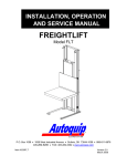
INSTALLATION, OPERATION
AND SERVICE MANUAL
LOW REACH PAN LIFT
Model XLR
P.O. Box 1058 • 1058 West Industrial Avenue • Guthrie, OK 73044-1058 • 405-282-5200 •
FAX: 405-282-8105 • www.autoquip.com
830XLR
Version 1.0
06/2003
TABLE OF CONTENTS
Identification and Inspection
3
Safety Signal Words
4
Safety Practices
5
Label Identification
8
Specifications
11
Lift Blocking Instructions
13
Installation Instructions
16
Operating Instructions
18
Routine Maintenance
19
General Maintenance
21
Replacement Parts List
32
Troubleshooting Analysis
33
IMPORTANT
Please read and understand this manual prior to installation or operation of this lift.
Failure to do so could lead to property damage and/or serious personal injury. If any
questions arise, call a local representative or Autoquip Corporation at 1-888-811-9876
or 405-282-5200.
PLANNED MAINTENANCE PROGRAM
A local Autoquip representative provides a Planned Maintenance Program (PMP) for
this equipment using factory-trained personnel. Call a local representative or Autoquip
Corporation at 1-888-811-9876 or 405-282-5200 for more information.
2
IDENTIFICATION & INSPECTION
IDENTIFICATION
When ordering parts or requesting information or service on this lift, PLEASE REFER
TO THE MODEL AND SERIAL NUMBER. This information is on a nameplate attached
to the leg assembly. Replacement parts are available from a local Autoquip distributor.
INSPECTION
Immediately upon receipt of the lift, a visual inspection should be made to determine
that it has not been damaged in transit. Any damage found must be noted on the
delivery receipt. In addition to this preliminary inspection, the lift should be carefully
inspected for concealed damage. Any concealed damage found that was not noted on
the delivery receipt should be reported in writing to the delivering carrier within 48 hours.
The following is a checklist that will aid you in the inspection of this lift:
1.
Examine entire unit for any signs of mishandling. Pay special attention to the
power unit and pushbuttons.
2.
Thoroughly examine all connections, making sure they have not vibrated loose
during transit, and inspect wiring for any signs of damage.
3.
After installation, raise the lift and inspect the base frame, platform, scissors
assembly, and cylinder plumbing connections.
3
SAFETY SIGNAL WORDS
SAFETY ALERTS (Required Reading!)
The following SAFETY ALERTS are intended to create awareness of owners,
operators, and maintenance personnel of the potential safety hazards and the steps that
must be taken to avoid accidents. These same alerts are inserted throughout this
manual to identify specific hazards that may endanger uninformed personnel.
Identification of every conceivable hazardous situation is impossible. Therefore, all
personnel have the responsibility to diligently exercise safe practices whenever exposed
to this equipment.
____________________________________________________________
DANGER !
Identifies a hazardous situation that presents the imminent probability of
death or of severe personal injury!!
_____________________________________________________________
WARNING!
Identifies a hazardous situation that has the potential of causing death or
serious personal injury.
CAUTION!
Identifies a hazardous situation that could lead to the possibility of personal
injury of death, and/or may result in equipment damage.
_____________________________________________________________
4
SAFETY PRACTICES
Read and understand this manual and all labels prior to operating or
servicing the lift. All labels are provided in accordance with ANSI
Z535.4.
DANGER !
Do not work under lift without maintenance device! To avoid personal
injury, NEVER go under the lift platform until the load is removed and the
scissors mechanism is securely blocked in the open position. See "Lift
Blocking Instructions" section.
DANGER!
To avoid personal injury, stand clear of scissors leg mechanism while lift is
in motion.
DANGER!
Do not install the lift in a pit unless it has a bevel toe guard or other
approved toe protection. A shear point can exist which can cause severe
injury to the foot.
DANGER!
HIGH VOLTAGE!! Disconnect and/or lock out the electrical supply to the
power unit prior to any maintenance being performed.
5
SAFETY PRACTICES
DANGER!
Extending the platform length or width beyond the factory limit could cause
the unit to tip, which could result in personal injury or death.
DANGER!
Do not attempt to remove the velocity fuse until the maintenance locks
securely support the lift and all hydraulic pressure has been removed from
the lifting cylinders and hydraulic hoses. Failure to do so could result in
personal injury or death!
WARNING!
Under no circumstances should the speed control orifice be removed from
the Deltatrol to obtain faster lowering speed. A loaded lift can reach
dangerous and destructive speed!!
WARNING!
All warning and information decals should be in place as outlined in the
“Label Identification” section. If decals are missing or damaged, they
should be replaced with new ones. Contact an Autoquip representative for
replacements.
6
SAFETY
PRACTICES
CAUTION!
Never run the pump for more than a couple of seconds without pumping oil.
This applies to low oil conditions, improper motor rotation, running the
pump against the relief pressure after the lift is fully raised against the
physical stops, running overloaded beyond capacity, or running at reduced
speed because of pinched or obstructed hydraulic lines.
CAUTION!
Do not continue to depress the “UP” button on the controller if the lift is not
raising or if the lift has reached the fully raised position. To do so may
result in permanent damage to the motor or pump.
CAUTION!
Do not operate the power unit on relief for more than a few seconds. When
on relief, the valve will make a squealing sound.
CAUTION!
Precautions should be taken to prevent the introduction of contaminates
such as dirt or other foreign material into the system through open fittings,
pipes or disassembled components. Contamination will ruin the hydraulic
system.
CAUTION!
Use only approved oils in the lift. See “Specifications” section.
7
LABEL IDENTIFICATION
2
5
1
3
4
Figure 1 Label Placement Diagram
XLR
Item No.
1
2
3
4
5
Qty
2
4
1
1
2
Description
Caution – Familiarize Yourself With Operators Manual
Danger – Do Not Put Hands or Feet . . .
Autoquip Serial Number Nameplate
Fill with Recommended Oils Only
Capacity
8
Part No.
36401487
36430050M
36401511
36400661
36401594
LABEL IDENTIFICATION
Note: Labels shown here are not actual size.
Figure 2 Label 36401487
CUT LINE
Figure 3 Label 36430050M
Figure 4 Label 36401511
9
LABEL IDENTIFICATION
Figure 5 Label 36400661
Figure 6 Label 36401594
10
SPECIFICATIONS
(in.)
36
36
36
36
36
36
36
36
36
Lifting
Capacity
(lbs.)
2000
2000
2000
3000
3000
3000
4000
4000
4000
Lowered
Ht.
(in.)
1/2
1/2
1/2
1/2
1/2
1/2
1/2
1/2
1/2
Side
Reach
-Over
(in.)
4
4
4
4
4
4
4
4
4
48
48
48
48
48
48
48
48
48
2000
2000
2000
3000
3000
3000
4000
4000
4000
1/2
1/2
1/2
1/2
1/2
1/2
1/2
1/2
1/2
4
4
4
4
4
4
4
4
4
Model
Travel
36XLR2040
36XLR2046
36XLR2052
36XLRA3040
36XLRA3046
36XLRA3052
36XLR4040
36XLR4046
36XLR4052
48XLR2040
48XLR2046
48XLR2052
48XLRA3040
48XLRA3046
48XLRA3052
48XLR4040
48XLR4046
48XLR4052
Platform
Size
(in.)
40 x 48
46 x 48
52 x 48
40 x 48
46 x 48
52 x 48
40 x 48
46 x 48
52 x 48
Base
Size
(in.)
40 x 48
46 x 48
52 x 48
40 x 48
46 x 48
52 x 48
40 x 48
46 x 48
52 x 48
40
46
52
40
46
52
40
46
52
40
46
52
40
46
52
40
46
52
x
x
x
x
x
x
x
x
x
64
64
64
64
64
64
64
64
64
x
x
x
x
x
x
x
x
x
64
64
64
64
64
64
64
64
64
Edge
Load
Capacity
(lbs.)
1000
1000
1000
1000
1000
1000
2000
2000
2000
1000
1000
1000
1000
1000
1000
2000
2000
2000
Speed
(sec.)
24
24
24
*
*
*
24
24
24
Shipping
Wt
(lbs.)
950
990
1030
1185
1225
1265
1040
1095
1150
32
32
32
*
*
*
32
32
32
1490
1530
1570
1345
1400
1455
1260
1315
1370
* Depends on air supply
LOAD CAPACITY
The load capacity rating is stamped on a metal plate attached to the lift. This figure is a
net capacity rating for a lift furnished with the standard platform. The relief valve of the
pumping unit has been set to raise the weight, plus a small amount for overload. Where
gravity roll-sections, special tops, etc, are installed on the lift after leaving the plant,
deduct the weight of these from the load rating to obtain the net capacity. Lifts should
not be overloaded beyond the established capacity as damage and/or personal
injury may result.
UNBALANCED LOADING
The stabilization provided is basically for balanced loads. If special attachments are
needed to extend beyond the length and/or width dimensions of the pla tform, consult
the factory for approval of all attachments or modifications to this equipment. Autoquip
does not foresee and can not anticipate unauthorized modifications to this lift which may
adversely affect the performance or safety of the lift and potentially cause permanent
damage to the lift, which could in turn lead to severe injury or death.
11
SPECIFICATIONS
PUMP PRESSURE
This lift incorporates a positive displacement pump machined to a high degree of
accuracy and specially adapted to requirements of higher-pressure ranges over that of
a standard pump. Therefore, standard factory models of the same manufacture cannot
replace it.
The pump can operate efficiently at intermittent pressures up to 3200 PSI and
continuous duty to 2500 PSI. The safety relief valve in the pump assembly is factoryset to stay within the parameters of the pump and lift requirements.
12
LIFT BLOCKING INSTRUCTIONS
WARNING !
Only authorized personnel should perform inspection or maintenance
and service procedures. Unauthorized personnel attempting these
procedures do so at the risk of personal injury or death.
DANGER !
Failure to properly adhere to lift blocking procedures is to risk the
sudden and uncontrolled descent of the lift during maintenance or
inspection. A falling lift can cause severe injury or death.
This procedure describes the only factory-approved method of working under a lift.
Follow these instructions EVERY time you plan to reach or crawl beneath the lift to
perform service or maintenance – no matter how momentary that might be.
If the factory-provided maintenance devices are damaged or missing, stop immediately
and consult the factory for assistance. The manufacturer is not liable for your failure to
use the approved maintenance devices and procedures that have been provided.
1. All load must be removed from the lift prior to engaging the maintenance devices.
These devices are designed to support an unloaded lift only. Failure to remove
the load from the lift prior to blocking could cause the failure of the maintenance
devices and allow the lift to fall unexpectedly. This can result in personal injury
or death, or permanent damage to the maintenance devices and/or the lift.
2. Raise the lift to its fully raised position. If you do not, the maintenance devices
may not be able to be placed properly in their designed blocking position.
3. Locate both hinged maintenance locks permanently welded outside the base
frame on the roller end of the lift base legs. Both locks must be flipped over and
resting inside the base frame and thus in the roller path of the lift (See Figure 7).
4. Lower the lift platform until the leg rollers make contact with both maintenance
locks. Re -check to ensure that both devices are fully and properly engaged with
the leg rollers. If both left and right maintenance locks are not fully engaged the
lift could fall unexpectedly, resulting in permanent damage to the devices or the
lift.
13
LIFT BLOCKING INSTRUCTIONS
FLIP-OVER MAINTENANCE
LOCKS SHOWN IN PLACE ON
BOTH SIDES OF BASE FRAME.
Figure 7 Maintenance Locks
14
LIFT BLOCKING INSTRUCTIONS
DANGER !
If for any reason you are unable to lower the lift completely onto the
maintenance device(s), stop immediately and consult the factory.
Failure to properly use the factory approved maintenance device(s)
could result in severe injury or death.
5. Once the maintenance devices are properly and securely engaged, continue to
press the down button, valve or switch for an additional 5-10 seconds to relieve
all pressure in the hydraulic system (it could take longer in a pneumatic system).
WARNING !
Failure to relieve operating system pressure could result in the
sudden and unexpected release of high pressure fluids (or air) during
maintenance and/or repair of the lift and result in severe injury or
death.
6. Follow OSHA electrical lock-out/tag-out procedures. Disconnect and tag all
electrical and/or other power sources to prevent an unplanned or unexpected
actuation of the lift.
7. Once inspection or work is complete, reverse the performance of the steps
above to raise the lift off the maintenance devices and flip the devices back into
their designated storage positions outside the base frame.
DANGER !
HIGH VOLTAGE!! – Disconnect and/or lock out the electrical supply to
the power unit prior to any installation or maintenance being
performed.
15
INSTALLATION INSTRUCTIONS
1.
Make sure installation area is clean before starting.
2.
If the permanent electrical work is not complete, some means of temporary lines
with an on-off device for the power supply should be set up for testing purposes.
3.
Place the lift in the installation area.
CAUTION!
When moving the lift, do not attempt to pick it up by the
platform; it is hinged and could be damaged. Pick up the lift
from under the base frame ONLY using a strap sling.
4.
Make temporary electrical connections and permanent hydraulic connections.
Raise the lift approximately one foot using the “UP” button. Then lower the lift
back to fully collapse, holding the “DOWN” button for approximately 60 seconds.
Repeat this process five to seven times to bleed any air out of the hydraulic
system.
5.
Raise the lift to the top of its travel and make positioning adjustments. Check for
the proper height. If needed, shim to the desired height. DO NOT “spot” shim.
Shim the full length of the base frame. This will prevent the frame from sagging
under an exceptionally heavy load.
DANGER !
Do not work under lift without Maintenance Device! To avoid
personal injury, NEVER go under the lift platform until the load
is removed and the scissors mechanism is securely blocked in
the open position. See "Lift Blocking Instructions" section.
6.
The base frame of the lift has pre-drilled holes for lagging it securely to the floor.
Mark the holes, drill, and install with anchors. Lifts with oversize platforms have
minimum pull out requirements of 2,000 lbs. for each anchor.
7.
Make permanent electrical connections and operate the lift through a few cycles.
16
INSTALLATION INSTRUCTIONS
CLEAN UP
1.
Clean up any debris from the area. A clean installation makes a good impression
and creates a much safer environment!
2.
Touch-up paint is available from Autoquip for repair of damaged paint surfaces.
WARNING!
All DANGER, WARNING, and CAUTION labels and informational
decals and plates must be intact and in place on the lift. Contact
an Autoquip representative if labels are missing or damaged.
See “DANGERS, WARNINGS, and CAUTIONS” section of this
manual.
17
OPERATING INSTRUCTIONS
1.
Scissors lifts have maximum lifting capacity ratings (See the “Specifications”
section). The safety relief valve has been factory set to open at a point slightly
above the rated load and allows the oil to bypass into the reservoir. The safety
relief valve should not be adjusted for any reason as it could cause the motor
or pump to prematurely burn out. Applying loads exceeding the rated capacity of
the lift may result in excessive wear and damage to the lift.
2.
This type of lift is designed primarily for in-plant applications and is furnished with
constant-pressure pushbutton controls. Actuating the "UP" button will cause oil to
enter the cylinders and the lift will rise.
3.
When the desired height or upward travel of the platform is attained, removing the
operators’ hand from the switch or button deactivates the “UP” circuit. The oil stops
flowing and the upward movement will stop. Once the control switch or button is
released the cylinders are locked into position at this height by a check valve in the
circuit .
4.
To lower the lift, activate the "DOWN" button. Opening the down control valve
allows the oil in the cylinders to flow through the down valve at a controlled rate
and return oil to the reservoir.
5.
When the desired height or downward travel of the platform is attained, removing
the operator’s hand from the switch or button deactivates the “DOWN” circuit. The
oil stops flowing from the cylinders and the downward movement will stop. Once
the control switch or button is released the cylinders are locked into position at this
height by a check valve in the circuit .
CAUTION!
Do not operate the power unit on relief for more than a few
seconds. When on relief, the valve will make a squealing sound.
18
ROUTINE MAINTENANCE
Normally scissors lifts will require very little maintenance.
However, a routine
maintenance program could prevent costly replacement of parts and/or downtime.
WARNING!
To avoid personal injury, NEVER go under the lift platform or perform any
maintenance on the lift until the load is removed and the scissors
mechanism is securely blocked in the open position. See "Lift Blocking
Instructions" section.
MONTHLY INSPECTION
1. Check oil level (see oil recommendations in this section) and add appropriate oil
when necessary.
2. Check for any visible leaks. Correct as necessary.
3. Check any unusual noise when it occurs.
necessary.
Determine the source and correct as
4. Check the snap rings at all rollers, if not in place, and/or secure, replace or repair
immediately.
5. Check all rollers for signs of wear. Replace as necessary.
6. Do not grease roller or axles; they have lifetime-lubricated bearings.
7. Check all wiring for looseness or wear. Repair at once.
OIL REQUIREMENTS
Change oil yearly, or more frequently if it darkens materially or feels gummy or gritty.
Do not use hydraulic-jack oil, hydraulic fluids, brake fluids, or automatic transmission
fluid.
19
ROUTINE MAINTENANCE
Oil Viscosity Recommendations
Environment
Recommended Oil
(Ambient Temperatures)
Indoor location, variable
10W30 or 10W40
temperatures (30 - 100° F)
Multiviscosity motor oil
Indoor location, consistent
SAE-20W motor oil
Temperatures (70° F)
Outdoor location, (-10 - 100° F)
SAE 5W30
Multiviscosity motor oil
Cold-storage warehouse
5W30 Multiviscosity
(10 - 40° F)
motor oil
Freezer (-40° F to 0° F)
Consult Factory
OIL CAPACITY
Standard polyethylene tank capacity is approximately five quarts.
PIPE THREAD SEALANT
Loctite PST #567 pipe thread sealant or equivalent is recommended. Do not use
Teflon tape. Tape fragments can cause malfunctioning of the hydraulic system.
20
GENERAL MAINTENANCE
CYLINDER REPLACEMENT
1. Set the lift in the maintenance position (See LIFT BLOCKING INSTRUCTIONS on
page 13.)
2. Unbolt the two hex head bolts that retain each of the cylinders to the platform.
3. Press and hold the “Down” button to allow the cylinders to retract to a position where
they can be removed from the platform connection.
4. Disconnect electrical power. Always shut off the main electrical switch when
maintenance is to be performed and flollow OSHA lockout-tagout procedures.
5. Disconnect the hydraulic hose from the cylinder.
WARNING!
Do not remove the base clevis pin. This will cause the lift to
collapse!
6. The cylinder can now be pulled out of the base socket and removed.
7. Replace cylinder using same procedure in reverse order.
21
Figure 8 Ram Detail
22
AIR BLEEDER SCREW
W/ WASHER
ROD END STOP
DETAIL A
ROD BUSHING
RAM CASING
SEAL/PACKING GLAND
BACKUP RING
QUAD RING
RAM PLUNGER
(SHOWN IN RETRACTED
POSITION FOR SEAL
REPLACEMENT)
RAM CASING
RAM PLUNGER
(1-1/2" DIA.)
DETAIL A
1/4" NPT PORT
(4) ROD BUSHINGS
GENERAL MAINTENANCE
GENERAL MAINTENANCE
VELOCITY FUSE REPLACEMENT
DANGER !
Do not attempt to remove the velocity fuse until the lift is securely
supported with the maintenance locking devices and all hydraulic pressure
has been removed from the lifting cylinders and hydraulic hoses. Failure
to follow these instructions could result in personal injury or death!
Never attempt to take a velocity fuse apart and repair it. These are precision devices
that are factory assembled under exacting conditions. Velocity fuses should always be
replaced.
1.
The arrow on the exterior surface of the velocity fuse shows the direction of the
restriction to the oil flow. The arrow should always point away from the cylinder.
2.
Do not use Teflon tape on the threaded connections of a velocity fuse. Tape
fragments can cause malfunctioning of the fuse.
3. Check all fitting connections for hydraulic leaks and tighten as necessary.
HOSE ORIENTATION
To prevent damage to the cylinder hose and possible failure of lift, it is necessary to
establish a correct hose shape and pattern of movement as follows:
1. Raise the lift to its full height and block securely. See “Lift Blocking Instructions”.
2. Install one end of the new hose to the cylinder elbow fitting.
3. Since the hose is fixed at both ends, it is possible to put a twist in the hose that will
allow it to describe the same pattern each time the lift is operated.
4. Lower the lift carefully and check to see that the hose is free and clear of the cylinder
and the leg assembly. If not, twist the hose in the direction necessary to clear it of
any obstruction and then lock the swivel fitting securely.
23
GENERAL MAINTENANCE
Figure 9 Hydraulic Schematic
24
GENERAL MAINTENANCE
WIRING AUTOQUIP "SUPER TORQUE' MOTORS
Because Autoquip "Super-Torque" motors actually deliver substantially more
horsepower than their nameplate rating, they must always be wired for heavier currentdraw than standard motors of the same nameplate rating. However, because of the
"Super-Torque" motor’s starting efficiency and superior running characteristics, circuit
components do not have to be as large as for standard motors of equal delivered
horsepower.
The following chart should be observed in connecting these motors to power sources,
remembering that, where 115-Volt operation is contemplated, the current-draw is too
heavy for plugging into ordinary lighting circuits. Heavy wire must be used all the way to
the power-source.
HP and Source
¾ HP / 115 V/60 CY/1 PH
Fuse
Size
45 A
Circuit
Breaker
40 A
¾ HP / 230 V/60 CY/1 PH
25 A
20 A
1½ HP / 208-230 V/60 CY/3 PH
15 A
10 A
1½ HP / 460 V/60 CY/ 3 PH
7.5 A
5A
NOTE: For larger horsepower motors, consult factory.
MOTOR CONNECTION DIAGRAMS
25
Figure 10 Electric Schematic; 115V/1Ph
26
(RED)
OPTIONAL FOOTSWITCH W/ GUARD (NEMA 1) SHIPPED
LOOSE WHEN ORDERED. TO BE INSTALLED AND WIRED
(BY OTHERS)
3.
TYPICAL PILOT CONTROLS ONLY
ELECTRICAL SCHEMATIC
TRANSFORMER PRIMARY CONNECTION DIAGRAMS ARE
LOCATED ON INSIDE OF FRONT COVER.
(GRN)
L1
(WHEN USED)
(BLACK)
(GRN.)
(WHITE)
(BLACK)
"UP" LIMIT
SWITCH
(XF)
2.
PUSHBUTTON
(WHITE)
2.5 AMP FUSE
MOTOR STARTER, CONTROL TRANSFORMER, OVERLOADS,
AND FUSES TO BE MOUNTED IN NEMA 1 ENCLOSURE,
PRE-WIRED, AND MOUNTED TO POWER UNIT.
L2
1.
FOOT SWITCH
SEE NOTE #3
(GRN)
115 VOLT
60 CYCLE
1 PHASE
L1
FUSED DISCONNECT
(BY OTHERS)
TRANSFORMER
(ORANGE)
T3
L3
T1
T2
O.L.
L2
DN. SOL.
(BLUE)
O.L. RELAY
CONTACT
MOTOR STARTER
L2
CONTACTOR
COIL
24V.
115V.
L2
L1
MOTOR STARTER
CONTACTS
L1
CONNECTION No. ON DEVICE.
STANDARD PUSHBUTTON
COLOR CODE
ELECTRICAL LEAD (PIG TAIL)
IDENTIFICATIONS
BLACK - MOTOR
WHITE - MOTOR
ORANGE - DOWN SOLENOID
RED - DOWN SOLENOID
GREEN - EQUIPMENT GROUND
(WHITE)
(BLACK)
MOTOR:
3/4 HORSEPOWER
115 VOLT
60 CYCLE
1 PHASE
GENERAL MAINTENANCE
Figure 11 Electric Schematic; 230V/1Ph
27
OPTIONAL FOOTSWITCH W/ GUARD (NEMA 1) SHIPPED
LOOSE WHEN ORDERED. TO BE INSTALLED AND WIRED
(BY OTHERS)
3.
TYPICAL PILOT CONTROLS ONLY
ELECTRICAL SCHEMATIC
L1
(WHEN USED)
TRANSFORMER PRIMARY CONNECTION DIAGRAMS ARE
LOCATED ON INSIDE OF FRONT COVER.
(GRN)
(GRN.)
(WHITE)
(BLACK)
"UP" LIMIT
SWITCH
(XF)
2.
PUSHBUTTON
2.5 AMP FUSE
MOTOR STARTER, CONTROL TRANSFORMER, OVERLOADS,
AND FUSES TO BE MOUNTED IN NEMA 1 ENCLOSURE,
PRE-WIRED, AND MOUNTED TO POWER UNIT.
L2
1.
FOOT SWITCH
SEE NOTE #3
(GRN)
230 VOLT
60 CYCLE
1 PHASE
L1
FUSED DISCONNECT
(BY OTHERS)
TRANSFORMER
T3
L3
T1
T2
O.L.
L2
DN. SOL.
(BLUE)
O.L. RELAY
CONTACT
MOTOR STARTER
L2
CONTACTOR
COIL
24V.
230V.
L2
L1
MOTOR STARTER
CONTACTS
L1
CONNECTION No. ON DEVICE.
STANDARD PUSHBUTTON
COLOR CODE
ELECTRICAL LEAD (PIG TAIL)
IDENTIFICATIONS
BLACK - MOTOR
WHITE - MOTOR
ORANGE - DOWN SOLENOID
RED - DOWN SOLENOID
GREEN - EQUIPMENT GROUND
(WHITE)
(BLACK)
MOTOR:
3/4 HORSEPOWER
230 VOLT
60 CYCLE
1 PHASE
GENERAL MAINTENANCE
(WHT)
28
(WHT)
(GRN)
(GRN)
Figure 12 Electric Schematic; 208-230-460V/3Ph
FOOTSWITCH IS SHIPPED LOOSE FOR INSTALLATION
BY OTHERS (WHEN ORDERED).
3.
TYPICAL PILOT CONTROLS ONLY
ELECTRICAL SCHEMATIC
TRANSFORMER PRIMARY CONNECTION DIAGRAMS ARE
LOCATED ON INSIDE OF FRONT COVER.
2.
(WHEN USED)
MOTOR STARTER, CONTROL TRANSFORMER, HEATERS,
AND FUSES TO BE MOUNTED IN NEMA 1 ENCLOSURE,
AND PRE-WIRED TO POWER UNIT.
(RED)
6
6 (RED)
L1
5
4
115VAC-(RED)
3
(A2)
DN. SOL.
3
3
3
(WHITE)-115VAC
3 (BLUE)-24VAC
O.L. RELAY
CONTACT
(95)
(96)
TRANSFORMER
MOTOR STARTER
(X2)
L2
HEATERS
O.L.
MOTOR STARTER
CONTACTS
CONTACTOR
COIL
(A1)
2
24VAC-(BLACK) 6
(X1)
(GRN.)
4
"UP" LIMIT
SWITCH
(XF)
(BLK)
4
PUSHBUTTON
2
2
SECONDARY FUSE
4 (BLK)
2
L3
L2
1.
FOOT SWITCH
SEE NOTE #3
2
2
L1
FUSED DISCONNECT
(BY OTHERS)
T3
T2
T1
ELECTRICAL LEAD (PIG TAIL)
IDENTIFICATIONS
2
CONNECTION No. ON DEVICE.
STANDARD PUSHBUTTON
COLOR CODE
BLACK - MOTOR
WHITE - MOTOR
ORANGE - DOWN SOLENOID
BLUE - DOWN SOLENOID 3
GREEN - EQUIPMENT GROUND
RED - MOTOR LEAD
3
4
GENERAL MAINTENANCE
GENERAL MAINTENANCE
Figure 13 Guarded Footswitch Assembly
29
GENERAL MAINTENANCE
Figure 14 Pushbutton Assembly
30
GENERAL MAINTENANCE
Figure 15 Limit Switch Wiring Diagram
31
REPLACEMENT PARTS LIST
PART #
20001137
20022877
20023925
24002008
24012502
30000020
30300016
32701290
33000680
34000018
34000257
35103380
35105130
35107910
35107980
35107990
35108050
36202141
41050139
41501776
41800640
45400082
20013900
45503150
47900006
52500485
52502903
52600269
DESCRIPTION
Tongue & Groove Coupling
18DU16 Bushing
24DU16 Bushing
Washer, 1-1/8” x 1/64” Thick
Washer, 1-1/2” x 1/16” Thick
Motor, ¾ HP/1 PH
Motor, 1 ½ HP/3 PH
Down Solenoid Coil, 24 VAC
Transformer
Limit Switch
Limit Switch Arm
Foot Switch and Guard
Pump, 1.4 GPM/3450 RPM with 24V coil
Control Assembly 115V/1PH
Control Assembly 230V/3PH
Control Assembly 460V/3PH
Control Assembly 230V/1PH
Pushbutton Assembly
Suction Strainer
Flow Control
Velocity Fuse
Retaining Ring, 1 1/8”
Retaining Clamp, 1-1/4”
Packing Kit
Vent Plug
Roller Pin, 1 1/8” diameter x 2” long
Clevis Pin, 1 1/8” diameter x 2-1/2” long
Roller Assembly, 3” OD x 1 1/8” ID
32
TROUBLESHOOTING ANALYSIS
DANGER !
To avoid personal injury, NEVER go under the lift platform until the load is
removed and the scissors mechanism is securely blocked in the open position.
See "Lift Blocking Instructions" section.
PROBLEM
Lift raises, then lowers back
slowly.
Lift lowers very slowly.
POSSIBLE CAUSE AND SOLUTION
•
The "Down" solenoid may not be seating.
Remove the solenoid coil and check again. If
the lift does not hold with the solenoid coil
removed, the down valve cartridge should be
removed and cleaned or replaced as necessary.
•
The oil line, hose, or fitting may be leaking.
Check and repair if necessary.
•
The “check valve” in the pump assembly may
not be seating. This is indicated by the pump
shaft and motor turning backward on their own
with no power applied. Generally, this condition
can be heard. Replace the pump assembly.
•
The down-solenoid is not operating properly due
to dirt or damage.
•
Check for pinched tubing or hose. Where pipe
is used, check for obstruction in the line.
•
The oil is extremely viscous due to low ambient
temperatures. Add or replace with lower weight
oil that stays thinner in cold conditions (5W-15,
etc.)
33
TROUBLESHOOTING ANALYSIS
PROBLEM
Lift does not raise.
POSSIBLE CAUSE AND SOLUTION
•
The motor rotation for a 3-phase motor may be
reversed. Reverse only two motor electrical leads.
•
Check for a line or hose leak.
•
Check for oil shortage in the reservoir. Add oil as
necessary (See Oil Requirements in the “Routine
Maintenance” section.)
•
The load may exceed the rating.
(See the
“Specifications” section.) Remove the excess load.
•
The suction filter may be clogged, starving the
pump. Remove and replace the filter. Drain and
replace the oil.
•
The suction line may be leaking air due to a loose
fitting. Tighten as needed.
•
The breather holes in the reservoir fill plug may be
clogged. Remove and clean.
•
The voltage at the motor terminals may be too low
to run the pump with the existing load. Check by
measuring the voltage at the motor terminals, or as
near as possible, while the pump is running under
load. Reading the source voltage or pump-idling
voltage is meani ngless. Inadequate or incorrect
wiring can starve the motor when the source
voltage is ample. Correct as necessary.
•
The "Down" valve may be energized by faulty wiring
or stuck open. Remove the solenoid and check.
•
The motor may be single phasing. Check wiring,
fuses, etc.
•
The pump may be seized if motor is humming or
blowing fuses on overload protection devices.
Remove the pump. The pump should be able to be
rotated by hand. Check for cracks in the housing.
•
The down solenoid valve stem may be bent,
causing the valve to be stuck open. Replace the
down solenoid valve.
34
TROUBLESHOOTING ANALYSIS
PROBLEM
Lift won’t lower.
POSSIBLE CAUSE AND SOLUTION
•
The solenoid coil may be incorrectly wired,
burned out, not rated for the voltage, or the line
voltage may be excessively low. Check voltage
near the coil.
•
The velocity fuse may be locked. Do not
attempt to remove the velocity fuse. The
following steps should be followed:
1. Remove the load from the lift. Inspect all
fittings, hoses, and other hydraulic components
for leads or damage.
2. If no leak or damage is noticed, attempt to
pressurize the lifting cylinder by depressing the
“UP” button on the controller for a few seconds.
Immediately up releasing the “UP” button,
depress the “DOWN” button. If the lift starts to
lower, continue pressing the “DOWN” button
until the lift is in the fully lowered position.
3. If the lift does not lower after trying Step 2,
wait approximately 10 – 15 minutes for the
pressure in the hydraulic system to equalize.
Then, depress the “DOWN” button until the lift is
in the fully lowered position.
4. Once the lift is in the fully lowered position,
bleed the air from the hydraulic system by
depressing the “DOWN” button. Hold the
“DOWN” button for approximately 60 seconds.
Repeat this process 8 – 10 times. This step
may need to be repeated several times to fully
remove the air in the system by raising the lift to
50% of its travel then lowering. Bleed air from
the bleeder screw on top of the cylinder.
•
Should the above steps not correct the problem,
contact Autoquip to obtain instruction for further
action.
35
TROUBLESHOOTING ANALYSIS
PROBLEM
Lift seems bouncy during
operation.
Motor labors or heats
excessively.
POSSIBLE CAUSE AND SOLUTION
•
Lower the lift to collapsed position and continue to
hold “DOWN” button an additional 10-30 seconds to
bleed air from the cylinder. Do not confuse spongy
or jerky operation with small surges that may occur
when operating on rough or uneven floors
•
Check for oil starvation.
•
The voltage may be low. Check at the motor
terminals while the pump is running loaded, not at
the line source or while the pump is idling.
Inadequate wiring can starve the motor even when
the source voltage is ample.
•
Most of Autoquip’s standard motors are rated for
intermittent duty (two minute run times with two
minute rests). If a single-phase motor is being run
more than 15 – 20 motor starts per hour, or a 3phase motor more than 200 starts per hour, the
problem may be motor over-heating.
•
Running agains t relief pressure unnecessarily due to
over loaded lift or hitting physical stops.
•
Failure to observe wiring diagram on nameplate for
proper voltage connections.
•
The pump may be binding from oil starvation, which
develops high internal heat. Check for low oil level
or closed breather holes in the reservoir fill plug.
The pump can be irreparably damaged by oil
starvation and may have to be replaced.
36