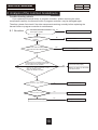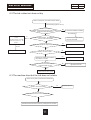
1
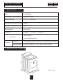
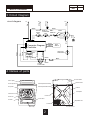
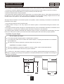
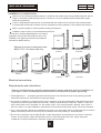
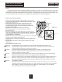
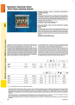
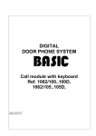
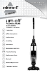
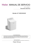
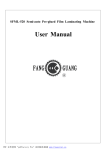
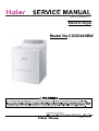
Order No. TL1309S001V1.2
Electric Dryer
Model No.CGDE480BW
©2008 Haier Washing Machine
Edition:2014.04.22
Service Manual
Model No. CGDE480BW
Issue
Rev.
CONTENTS
1 . S p e c i f i a t i o n l i s t ……………………………………………………………………… 1
2 . D i m e n s i o n a l d r a w i n g ……………… ……………………………………… ……… 1
3. Circuit diagram
…………………………………………………………………… 2
4. Names of parts
………………… ………………… ………………… …………… 2
5 . U s a g e o f t h e o p e r a t i o n k n o b s………………………………………… …………
3
6 . P r o d u c t s b r i e f a n d n e w f e a t u r e s …………………………………… …………… 4
7 . K e y p o i n t i n i n s t a l l a t i o n a d j u s t m e n t a n d d i s a s s e m b l y ………………………… 6
8. Analysis of the common breakdowns ……………… …………………………… 10
Service Manual
Issue
Rev.
Model No. CGDE480BW
1 Specification List
Model
CGDE480BW
Rated voltage rated frequency
120V/240V 60Hz
Rated dry capacity
6.5 Cu.ft(Drum Size)
Rated power consumption in drying
4800W
Rated input consumption of motor
379W
Net W eight(kg)
About 57kg
Dimension
L 686mm
H 1097mm
User's manual ,
Accessories
Programs
W 718mm
product registration card
Automatic
Setting drying program according to the laundries automatically
Manual setting
the time for setting : 10 min, 30 min, 60 min, 90 min
1097
2 Dimensional Drawing
718
686
1
Unit:mm
Service Manual
Issue
Rev.
Model No. CGDE480BW
N
G
L2
Black
Red
L1
Green
White
White
BELT
Back-up
Thermostat SWITCH
Gray
Gray
Gray
Yellow
5
4
White
Relay
6
1
Yellow
Gray
Door
Switch
G
High Limit
Thermostat
Orange
Red
Orange
Orange
Blue
Purple
Computer Program
Controller
Motor
Green
Thermal
Limiter
Blue
circuit diagram
White
3 Circuit Diagram
Orange
Brown
Control
Thermostat
Brown
Black
Heater
4 Names of parts
back baffle
control plate
control panel
fasten button
thread-protected board I
front plate
thread-protected board II
cabinet
nameplate
whisk leaf
Power line
barrel roll
front door
lint filter
adjustable foot
shutter
lock body
exhaust duct
2
Service Manual
Issue
Rev.
Model No. CGDE480BW
Understanding the control panel
1
3
4
2
5
Temp Button: (1)
● Use to set drying temperatures.There are four available drying temperatures to choose from:High,Medium,Low
and No Heat.
Dry Level Button: (2)
● Used to set drying level.There are three available drying levels to choose from More,Normal and Less.
Cycle Select Dial:(3)
● Select from 3 Auto-Dry cycles (Heavy Duty , Normal and Delicates) or 4 Timed Dry Cycles
(10min,30min,60min,90min) or “Off” to shutdown the machine.
Start/Pause Button (4)
● Push to shart after selecting the dry cycle and seting the temperature . Push once to pause . Push again to start
after pushing
Cycle Progress:(5)
● This indicates the process the cycle is currently in . At the end of cycyle the dryer will automatically go in the wrinkle
saves mode . Here the dryer tub will tumble periodically for 1 hour after the dry cycle is completed . To stop simply
open the door and remove the clothes.
Note : Clean the lint filter before every use .
Service Manual
Issue
Rev.
Model No. CGDE480BW
6 Product Brief and New Features
C
Product
briefs
1) Program control
As the control center of the appliance, the program controller directs the appliance to meet the
demand of the user like the brain of human body. This part has acquired the UL certification, with long
operation life and reliable performance.
2) Temperature sensor
The temperature sensor of this appliance has also acquired the UL certification. It acts as nerve
center during usage of the appliance. It is used to detect the dry degree or temperature, and can effectively
prevent the defects like the crimple of laundries owing to overheating.
5
3) Power transmission system
Rotation direction
3
4
2
1
During drying, Motor 1 transmits the driving power to Tumbler 5 through Belt 2 and
Multi-wedge belt 3. Then Tensioning wheel 4 tensions the belt under the action of
tensioning spring. At the same time, it also increases the transmission wrap angle of the
pulley, and improves the transmission efficiency of the belt. The motor rotates to one
single direction during drying. The tumbler will also rotate to one single direction. The
motor is centrifugal type, and has acquired the UL certification, with strong driving power
and long operation life.
4) Air intake and exhaust system
The appliance collects air through shutter, and heats the air with electric heating thread. The air
exhaust system composed of volute impellers generates negative atmosphere pressure under the suction
force, and thus attracts the hot air into the tumbler to dry the laundries. The air intake and exhaust system
has high degree of tightness, and improves the thermal efficiency.
5) Heating system
The electric heating thread installed on the heating plate at the rear of the cabinet, is the heating
source of the appliance. The exchanging of cold and hot air is realized by it. The heating power of the
electric heating thread is about 4700W. It can raise the air temperature rapidly, and offer hot air continuously.
4
Service Manual
Issue
Rev.
Model No. CGDE480BW
6) Lint filter
It is a kind of wearing part, made of filter screen frame and screen cloth by one-time plastic injection.
When taking off the lint filter, please do not squeeze the screen cloth by force to avoid damaging the
cloth. At the same time, please clean it in time after each usage.
CNew features
Your dryer also has the following features for your convenience:
Dry sensor : (feature only active in auto dry cycle)
Thi s senses temperatur e in the drum.The dryer wil l automatically shut itself off.
En d of cycl e signal:
Your dryer is equipped with an audible signal that alert you every time when the dryer load is
finished drying.
Lint filter:
All dryers come with a lint filter that needs to be cleaned before or after every use.
Leveling legs:
You r dryer has four leveling legs which are located in the front and rear corners of your
dryer. After properl y placing your dryer or by turning them counter clockwise to lower your dryer.
Leveling legs can be adjusted by turning them clockwise to raise your dryer or by turning
them counte r clockwise to lower your dryer.
5
Service Manual
Issue
Rev.
Model No. CGDE480BW
7 Key points in installation, adjustment and disassembly
Select a suitable location for the dryer on a hard even surface away from direct sunlight or heat
source e.g. Radiators, baseboard heaters, cooking appliances etc . Any floor unevenness
should be corrected with leveling legs located on the bottom of the dryer.
Tools and materials required
Phillips head and flathead screwdrivers
Measuring tape ( 12ft.min.)
Channel-lock adjustable pliers
Duct tape
1 2 inch open end wrench
Carpenter's level
Rigid or flexible metal 4 inch ( 10.2 cm) duct
Vent hood
Electrical requirements
Power supply: 3 wire , 120 volt , 30 amp, 60Hz, 1 phase
Power supply cord kit:
(Not supplied when sold in the United States) the dryer MUST employ a 3-conductor power supply cord NEMA
10-30 type SRDT rated at 120 Volt AC minimum, 30 Amp, with 3 open end spade lug connectors with upturned
ends or closed loop connectors and marked for use with clothes dryer.
CUnpacking your dryer
1) remove all packaging material . This includes the foam base and all adhensive tape holding the dryer
acessories inside and outside.
2) inspect and remove any remains of packing, tape or printed material before using the dryer.
CExhaust system connections
CMaterials
Use only 4 inch (10.2.cm) diameter (minimum) rigid or flexible
INSTALL MALE FITTINGS IN CORRECT DIRECTION
metal duct and approved vent hood which has a swing-out damper
CORRECT
hat open when the dryer is in operation . When the dryer stops, the
dampers automatically close to prevent drafts and the entrance of
insects and rodents . To avoid restricting the outlet, maintain a
minium of 12 inches ( 30.5 cm) clearance between the vent hood
and the ground or any other obstruction . The vent flap should be able to remove freely.
MAXIMUM LENGTH
of 4''(10.2cm)Dia.Rigid Metal Duct
Number
of
90
turns
INCORRECT
MAXIMUM LENGTH
of 4''(10.2cm)Dia.Flexible Metal Duct
VENT HOOD TYPE
Number
of
90
turns
(Preferred)
Louvered
4''
21/2''
(10.2 cm)
(6.35 cm)
VENT HOOD TYPE
(Preferred)
Louvered
4''
21/2''
(10.2 cm)
(6.35 cm)
0
60ft. (18.28 m)
48ft.(14.63 m)
1
52ft. (15.84 m)
40ft.(12.19 m)
0
30ft. (9.14 m)
18ft.(5.49 m)
2
44ft. (13.41 m)
32ft.(9.75 m)
1
22ft. (6.71 m)
14ft.(4.27 m)
3
32ft. (9.75 m)
24ft.(7.31 m)
2
14ft. (4.27 m)
10ft.(3.05 m)
4
28ft. (8.53 m)
16ft.(4.87 m)
96
Service Manual
Issue
Rev.
Model No. CGDE480BW
After installation is completed, the following method must be used to determine if the exhaust system is acceptable:
1. Connect an inclined or digital manometer between the dryer and the point the exhaust connects to the dryer.
2. Set the dryer timer and temperature to air fluff (cool down) and start the dryer.
3. Read the measurement on the manometer.
4.The system back pressure MUST NOT be higher than 0.75 inches of water column. If the system back pressure is
less than 0.75 inches of water column, the system is acceptable. If the manometer reading is higher than 0.75 inches
of water column, the system is too restrictive and the installation is unacceptable.
Although vertical orientation of the exhaust system is acceptable, certain extenuating circumstances could affect the
performance of the dryer:
1. Only the rigid metal duct work should be used.
2. Venting vertical through a roof may expose the exhaust system to down drafts causing an increase in vent
restriction.
3. Running the exhaust system through an uninsulated area may cause condensation and faster accumulation of lint.
4. Compression or crimping of the exhaust system will cause an increase in vent restriction.
The exhaust system should be inspected and cleaned a minimum of every 18 months with normal usage. The more
the dryer is used, the more often you should check the exhaust system and vent hood for proper operation.
CLocation of your dryer
Do not install your dryer:
In an area exposed to dripping water or outside water conditions.
In an area where it will come in contact with curtains drapes, or anything that will obstruct of combustion
and ventilation air.
On carpet, floor must be solid with a maximum slope of inch (2.54 cm).
Installation in recess or closet:
The dryer installation in a bedroom, bathroom, recess or closet, must be exhausted outdoors.
Your dryer needs the space around it for proper ventilation.
A minimum of 120 square inches(774.2 square cm) of opening, equally divided at the top and bottom of
the door, is required. Air openings are required to be unobstructed when a door is installed. The full length of
the door is acceptable.
C
Rough-in dimensions
DIMENSIONS
50 3/5''
(128.5 cm)
DOOR OPEN 90
28 1/4''
(71.8 cm)
REAR VIEW
97
SIDE VIEW
Service Manual
Issue
Rev.
Model No. CGDE480BW
Installation in mobile home
C
Dryer must be exhausted outside (outdoors, not beneath the mobile home) using metal ducting that will not
support combustion. Metal ducting must be 4 inches (10.16 cm) in diameter with no obstructions. Rigid
metal duct is preferred.
If dryer is exhausted through the floor and area beneath the mobile home is enclosed, the exhaust system
must terminate outside the enclosure with the termination securely fastened to the mobile home structure.
Refer to previous pages for other important venting requirements.
Installation must conform to current Manufactured Home
Construction &Safety Standard(which is a Federal
Regulation Title 24 CFR-Part 32-80) or when such
standard is not applicable, with American National
Standard for Mobile Homes.
DO
DON'T
Warning: the dryer is designed under
ANSI z 21.5.1 for home use only.
Correct
DO
Correct
DON'T
DO
Incorrect
DON'T
Incorrect
Correct
Incorrect
CElectrical connections
CRequirements and instructions
Warning: the following are specific requirements for proper and safe electrical installation of
your dryer. Failure to following these instructions in this manual for proper grounding.
1. This appliance MUST be properly grounded. Electrical shock can result if the dryer is not properly grounded.
Follow the instructions in this manual for proper grounding.
2. Do not use an extension cord with this dryer. Some extension cords are not designed to withstand the amounts
of electrical current this dryer utilizes and can melt, creating electrical shock and/or fire hazard. Locate the
dryer within reach of the receptacle for the length power cord to be purchased, allowing some slack in
the cord. Refer to the pre-installation requirements in this manual for the proper power cord to be purchased.
3. A U.L. approved strain relief must be installed onto power cord. If the strain relief is not attached, the cord can be
pulled out of the dryer and can be cut by any movement of the cord, resulting in electrical shock.
4. Do not use an aluminum wire receptacle with a copper wired power cord and plug (or vice versa). A chemical
reaction occurs between copper and aluminum and can cause electrical shorts. The proper wiring and
receptacle is a copper wired power cord with a copper wired receptacle.
89
Service Manual
Issue
Rev.
Model No. CGDE480BW
Danger :
Improper connection of the equipment grounding conductor can result in a risk of electrical shock. Check with
a licensed electrician if you are in doubt as to whether the appliance is properly grounded. The dryer MUST be
connected to a grounded metal, permanent wiring system, or an equipment grounding conductor must be run with
the circuit conductors and connected to the equipment-grounding terminal or lead on the appliance.
4-wire cord connections
brass terminal
1. Remove the screws securing the terminal block access cover
and the strain relief mounting bracket located on the back of the
dryer in the upper corner.
2. Install a strain relief into the power cord entry hole of the
mounting bracket. Finger tighten the nut only at this time.
3. Thread a 30 Amp. Power cord, 245 IEC66(YCW) 450V/750V,
through the strain relief.
L1
4. Attach the power cable earthconductor to the silver
coloured centre terminal on the terminal block. Tighten
the screw securely.
5. Attach the remaining two power cable outer conductors to the
outer silver coloured terminals on the terminal block. Tighten both
screws securely. Warning:Do not make a sharp bend or crimp
wiring/conductor at connections.
6. Reattach the strain relief mounting bracket to the back of the dryer
with two screws. Tighten screws securely.
7. Tighten the screws securing the cable restraint firmly against the
power cable.
8. Tighten the tension relief nut securely so that the tension relief
does not turn.
9. Reinstall the terminal block cover.
Grounding
instruction:
Warning:
Caution:
Warning:
Warning:
8
N
L2
nut
tighten nut
to these threads
power cord
strain relief
mounting bracket
This appliances must be connected to a ground metal,permanent wiring system, or an
equipment-grounding conductor must be run with the circuit conductors and connected to the
equipment-grounding terminal or lead on the appliance.
Improper connection of the equipment-grounding conductor can result in a risk of electric shock.
Check with a qualified electrician or service representative or personnel if you are in doubt as to
whether the appliance is properly grounded.
Label all wires prior to disconnection, when servicing controls.Wiring errors can cause improper
operation and be dangerous. Check unit for proper operation after servicing.
Discard or destroy the carton and plastic bags after the dryer is unpacked. Children should not be
allowed to use them to play with. Cartons covered with rugs bedspreads, or plastic sheets can
become an airtight chamberand cause suffocation leading to death. Make all packing materials
inaccessible to children.
The instructions in this manual and all other literature included with this dryer can not cover every
possible condition and situation that may occur. Good safety practice and caution must be applied
when installing, operating and maintaining any appliances. After installing, if you are indoubt,
call a qualified electrician to install and wire the dryer.
9
Service Manual
Issue
Rev.
Model No. CGDE480BW
8 Analysis of the common breakdowns
Trouble-shooting charts
If you replace the thermal limiter or program controller without checking the other
components carefully, the thermal limiter or program controller may be damaged again.
Therefore, please first check if the other components working normally before replacing the
thermal limiter or program controller in maintenance.
8.1 No action
Cut off the power.Check if the door
of the dryer is closed?
No
Close the door.
Yes
No
Check if the belt is correctly
installed?
Correctly installed
Yes
Yes
Check if the wire connecting of the
motor and the PCB is disconnected?
Connect the wire properly
No
Check if the wire connecting of the back
up thermostat and the thermal limiter is ok?
You can replace or use ohmmeter
No
Check if the back-up thermostat is well?
Well: the resistance is 0Ω;
Broken: he resistance is infinite
Connect the wire properly
Replace the Back-up thermostat
or the thermal limiter.
Yes
No
Check if the PCB is good?
Replace the PCB
Yes
No
Check if the motor is good?
Replace the motor
Yes
No
Check if the wire unit is good
10
9
Replace the wire unit
Service Manual
Issue
Rev.
Model No. CGDE480BW
8.2 The tub rotates but does not dry
Switch on the power, push down the start button
Set timed drying (above 15 min)
Observe wether the
heater is aglow from the back of the machine
( while the power switches on )
Yes
No ventilating
No
Measure the resistance of the
heater
Well:The resistance is 10.3 ;
Broken:The resistance is
infinite;
Broken
Yes
Check the ventilation condition
Measure wether there is the voltage between
the two ends of the heater?
Check if the vent-pipe and the
vent-way is blocked
No
Check if the sequencer plug inserts correctly?
No
Correctly connected
Yes
Replace the heater
No
Check if the relay is well?
Replace the relay
Yes
No
Replace the PCB to check whether
this problem is solved?
Replace the PCB
Yes
No
Check if the control thermostat and high
limit thermostat can act?
Replace the control thermostat and
high limit thermostat
Yes
Check if the wire unit is good
8.3 The machine dries but the tub does not rotates
Switch on the power, push down the start button
Yes
Check if the belt is broken?
Yes
No
Check if the tensive arm unit is installed well?
No
Reinstall the tensive wheel unit and try rotating the tub manually
11
9
Replace the belt
Service Manual
Issue
Rev.
Model No. CGDE480BW
8.4 Too much noise in drying
The noise includes the harsh , the metallic bang and the big collision sound during drying ,
These are normal sounds such as vent-like sound and a grating ect.
Switch on the power, push down the start button
Search the root of the noise
No
Check if these come from the vibration
between the supporter in the front of the cabinet and the
cabinet or the abrasion between the support
wheel and the bracket of support wheel?
Yes
Fasten the support bracket or
replace the support wheel
No
If there is a noise from the tensive spring?
Yes
Check the tensive condition ,
replace the tensive spring
Yes
Fasten the heating ring and
the fasten screw
Yes
Adjust or replace the worm shell
No
If there is metallic bangs because the
screws of the heating ring become flexible?
No
If there is gratings between the impeller and
the worm shell?
12
9
Service Manual
Issue
Rev.
Model No. CGDE480BW
8.5 Error Display
Start the dryer IX the status lights is twinkling and the dryer no action
Error message:Door is not closed.
Troubleshooting:
No
Confirm that the door is closed
Close the door
Yes
Cut off the power. Check if the wire
connecting of the door switc and PCB is
disconnection?
Yes
Connect the wire properly
No
Check if the Door switch is good?
You can replace it or use ohmmeter,
Broken
Well:the resistence is 0 ;
Broken: the resistence is infinite;
Replace the door switch and make
sure wire is connected properly.
Well
Check if the PCB is good?
Broken
Replace the PCB
Well
Check if the wire unit is good?
13
9
No
Replace the wire unit
Sincere Forever
Group
Haier Industrial Park, No.1, Haier Road
266101, Qingdao, China
http://www.haier.com