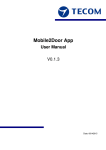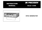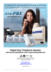
1
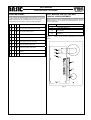
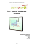
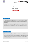
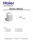
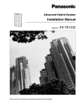
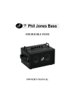
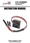
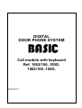
DIGITAL
DOOR PHONE SYSTEM
Call module with keyboard
Ref. 1062/100..100D,
1062/105..105D,
Version, April 8th, 2011
Software version 1.12
DIGITAL CALL MODULE REF. 1062/100..100D AND 1062/105..105D
GENERAL INFORMATION / TECHNICAL DATA
DIGITAL CALL MODULE WITH KEYBOARD
REF. 1062/100..100D
DIGITAL CALL MODULE WITH KEYBOARD
REF. 1062/105..105D
GENERAL INFORMATION
GENERAL INFORMATION
Digital call module with keyboard Ref. 1062/100..100D combined
with power supply GT1975 and doorphones is a full door phone
installation. It is based on MIWUS call module „Mod.525” (2
modules).
It is offered with two types of housing:
1062/100
- wall mounted without rain hood,
1062/100D - wall mounted with rain hood.
This call modules can be optionally flush-mounted with dedicated
frame ref. 525/RP2.
Digital call module with keyboard Ref. 1062/105..105D combined
with power supply GT1975 and doorphones is a full door phone
installation. It is based on MIWUS call module „Mod.525” (2
modules).
It is offered with two types of housing:
1062/105
- wall mounted without rain hood,
1062/105D - wall mounted with rain hood.
This call modules can be optionally flush-mounted with dedicated
frame ref. 525/RP2.
CONSTRUCTION OF THE CALL MODULE
CONSTRUCTION OF THE CALL MODULE
Digital call module with keyboard Ref. 1062/100..100D is made of
stainless steel. Particularly noteworthy is the metal illuminated
keyboard. The panel has all characteristics of vandal-proof panel.
Digital call module with keyboard Ref. 1062/105..105D is made of
stainless steel. Particularly noteworthy is the metal illuminated
keyboard. The panel has all characteristics of vandal-proof panel. In
addition this call module has built-in Dallas key reader.
TECHNICAL DATA
TECHNICAL DATA
Power supply:
From dedicated
GT1975
Control of electrical lock:
Operating temperature:
power
supply
Power supply:
From dedicated
GT1975
With built-in current control
Control of electrical lock:
With built-in current control
-20 °C ÷ +50 °C
Operating temperature:
-20 °C ÷ +50 °C
Dimension (H x W x D):
152 x 110 x 23 mm
(ref. 1062/100)
Dimension (H x W x D):
152 x 163 x 23 mm
(ref. 1062/105)
Dimension (H x W x D):
152 x 110 x 23-35 mm
(ref. 1062/100D)
Dimension (H x W x D):
152 x 163 x 23-35 mm
(ref. 1062/105D)
Dimension (H x W x D):
175 x 135 x 23.6 mm
(with frame 525/RP2)
Dimension (H x W x D):
175 x 188 x 23.6 mm
(with frame 525/RP2)
Weight:
0,8 kg
Weight:
0,8 kg
2
power
supply
CALL MODULES
USER MANUAL
DESCRIPTION OF TERMINAL BOARDS
OPENING THE DOOR
GENERAL CODES
KEYBOARD MODULE
We are able to open the door using one of 64, 4-digits general
opening codes.
To do it:
• Press # button,
VDD
GND
AC2
+C
-C
AC1
LU
0L
EI1
EI2
EI3
EI4
GND
OC2
OC1
PS
Input voltage + 18 V DC.
GND.
Input voltage AC.
Electrical lock output (+).
Electrical lock output (-).
Input voltage AC.
Doorphones line (riser).
GND.
Controlled input contact (configured in menu).
Controlled input contact (configured in menu).
Controlled input contact (configured in menu).
Controlled input contact (configured in menu).
GND.
Open collector output (configured in menu).
Open collector output (configured in menu).
Generator output (configured in menu).
BASIC FEATURES
•
•
•
•
•
•
•
•
Power doorphones,
Call to all doorphones,
Open door with general or individual codes,
Possibility of various EI1..EI4 input configuration, for example:
mailman button or direct call button,
Possibility of various OC1..OC2 output configuration, for
example: call switching on repeater (video control), output
activated by pressing doorphones additional button, code
activation,
Possibility of use PS output to attach local ring tone,
Programmable system,
System information shown on LED display.
USER MANUAL
CALL TO DOORPHONES
Each user can be called by entering relevant 4-digit code from
range 1…9999. Call codes (logical codes) are assigned to relevant
doorphones physical codes. By default this is made by 1 to 1
relocation (physical code number 1 corresponds to logical code
number 1). Each doorphone has unique physical resulted from
address setting in doorphone.
After entering code user can wait for 3 seconds to initiate call or
press # to call immediate.
•
•
(CONTACT
+C
–C)
WITH
Enter general code,
Press # button to confirm.
This function can be disabled in programming menu.
OPENING THE DOOR
INDIVIDUAL CODES
(CONTACT
+C
–C)
WITH
We are able to open the door using 1 of the individual 4-digits
opening code. To open door with this code first we have to enter
logical user code and then individual opening code which was
associated to it. Individual opening code can has from 5 to 8 digits.
To open the door:
•
Press # button,
•
Enter individual opening code (5 to 8 digits),
•
Press # button to confirm.
RELEASING EXO (CAN BE ATTACHED WITH OC1 OR
OC2) WITH GENERAL CODES
We are able to release OC1, OC2 outputs or electrical lock using
general opening codes (depending on configuration settings). It can
be realized by entering one of 64, 4-digits general opening codes.
To do it:
•
Double press # button,
•
Enter general opening code,
•
Press button # to confirm.
RELEASING EXO (CAN BE ATTACHED WITH OC1 OR
OC2) WITH INDIVIDUAL CODES
We are able to release OC1, OC2 outputs or electrical lock using
individual opening codes (depending on configuration settings). It
can be realized by entering flat number and then 4-digits opening
code.
To do it:
•
Press # button,
•
Enter general opening code (5 to 8 digits),
•
Press # button to confirm.
In case of mistake press ∗ button to cancel code, and enter correct
one.
• Called doorphones will ring as long as it was programmed (1 to
30 seconds). After this time call will be cancelled. Pickup time is
signalled by recurrent double call signal (this option can be
turned on) – from 1 to 30 seconds,
• Conversation is possible when user pick up the handset. During
conversation user can open the door (press open the door
button on doorphone). Pressing this button will generate
confirmation signal. The electrical lock will be open as long as
we programmed it (range 1 to 30 s). It will be indicated by
dashes on display.
Maximum time of conversation is between 1 to 120 s. After that time
in the receiver will be played signal to warn that the conversation is
nearly over, and after it, the conversation will be disconnected.
3
CALL MODULES
USER MANUAL
FUNCTION OF PS TERMINAL
Call module is equipped with PS terminal with connected generator.
Generator parameters can be programmed in programming menu.
It can be used with local ring tones (generator will work, if during
installation between terminals PS and GND there has been speaker
installed).
FUNCTION OF OC1 AND OC2 OUTPUTS
In this step we can choose 1 of 4 predefined levels of ring tone
volume.:
1
Volume level - quiet,
4
Volume level – loudest.
To save parameter press # button.
Default setting
0 – global settings (step 2.07)
3. DOOR OPEN CONFIRMATION IN DOORPHONE
Call module is equipped with two open collector type outputs - OC1
and OC2. Performance of these outputs can be programming in
programming menu.
P u
3
FUNCTION OF EI1…EI4 INPUTS
Call module is equipped with EI1…EI4 terminals. Performance of
these inputs can be programming in programming menu.
INDIVIDUAL USER SETTINGS
In BASIC system each user can change his own individual settings,
which are:
•
Change of ring tone,
•
Ring tone volume level adjustment,
•
Opening confirmation in doorphone,
•
Automatic opening after call,
•
Change of individual code,
For example: for flat number 1 with individual code 1234 you need
to enter: 0#11234#
After entering correct password the following will appear:
1
Choose function:
1. Ring tone,
2. Ring tone volume level,
3. Opening confirmation in doorphone,
4. Automatic opening after call,
5. Change of individual code,
1. RING TONE
1
In this step we can choose 1 of 3 available ring tones.
To save setting press # button.
Default setting
0 – global ring tone (step 2.06)
2. RING TONE VOLUME LEVEL
P u
4
0 – global settings (step 2.02)
4. AUTOMATIC OPENING THE DOOR AFTER CALL
4
In this step we can decide whether we want to automatically open
the door after call or not:
0
Disabled,
1
Enabled.
Default setting
-0
5. CHANGE OF INDIVIDUAL CODE
P u
5
In this step we can change individual user code. After entering this
step display will fade out:
•
Press ∗ to exit,
•
Enter new password and press # button to confirm.
After entering specific function we can:
•
Press ∗ button to exit,
•
Press # button to confirm,
•
Enter new value and press # button to confirm.
P u
Default setting
P u
To enter programming menu:
•
Press 0 button,
•
Press # button,
•
Enter individual code,
•
Press # button to confirm.
P u
In this step we can choose if we can have confirmation signal in
doorphones after opening the door:
0
Disabled,
1
After entering individual opening code preceded by single
pressing of # button or after opening the door with Dallas key,
2
After entering individual opening code preceded by double
pressing of # button ,
3
Both 1 and 2 situations.
2
NOTE:
Enter new 4 digit code without flat number prefix.
For example: Prefix for code 12345 is digit 1.
CALL MODULES
PROGRAMMING
PROGRAMMING FUNCTIONS
PROGRAMMING
In BASIC system, to simplify installation, call modules are provided
with preconfigured settings:
• Call codes within 1 to 100 range,
• To all call codes are assigned random individual opening
codes,
• Time of releasing electrical lock: 3 s,
• Time of call signal: 5 s,
• Time for pick up the handset: 20 s,
• Max conversation time: 120 s.
Thanks to this, to run BASIC system it is required only to connect
devices in accordance to appropriate scheme and to program
doorphones with their jumpers.
SOFTWARE UPGRADE FROM V1.00 OR OLDER TO
V1.10 OR NEWER.
After upgrading software from v.1.00 or older to v.1.10 or newer it is
required to use step 5.05 in programming menu.
SOFTWARE UPGRADE FROM V1.10 OR NEWER
In order to upgrade software from v1.10 to newer it is required to
follow below steps:
• Attach cable ref. 1062/60 to the PC,
• Run dogrywacz_2 programme,
• Attach cable ref. 1062/60 and connect the power supply to call
module,
• Select the correct COM port,
• Select „Data Backup” and press GO!,
• Select „Firmware upgrade” and press GO!,
• Select „Data Restore” and press GO!,
• After finish you can detach call module.
NOTE: Every time you press GO! it is required to wait until progress
bar moves from left to right.
Skipping “Data Backup” and “Data Restore” will cause loose of
configuration.
In case of upgrading from version older than 1.10 it is required to
select „Firmware upgrade” option in „Dogrywacz_2” program, and
then press GO! button. Then, in order to restore configuration you
need to enter step 5.05 in programming menu.
ENTERING PROGRAMMING MODE
After entering menu we can easily choose any location in
programming menu. To do it just enter first digit (group of
functions), then two another digits (particular function) and then
press # button to confirm.
After selecting function there will be shown its current parameter,
and we can:
•
Press shortly ∗ button to return to menu,
•
Press shortly # button to confirm,
•
Enter new value and then press and hold # button to confirm.
During programming call codes and opening codes it is required to
hold # button for about 1 second to confirm changes.
Example
We would like to enter step 01 of global settings.
To do it:
Press digit 2 (global settings)
P
2.
Enter 01:
P 2. 0 1
Press # to confirm.
Idle time in programming mode is 120 s. After this time system will
automatically exit programming mode.
NOTE!
If you enter value bigger than allowed for particular function,
then system will automatically change it to maximum allowed
value.
Example:
If allowed value is 10 and you enter 20 then system will
automatically change to 10.
In order to enter programming mode:
•
Double press 0 button,
•
Enter 8-digits access password,
•
Press # button to confirm.
Default password: 21082004
After entering correct password the following will appear:
P
0
In BASIC system there is two-level programming menu. First level
is defined with 0 to 6 digit and means group of parameters. Second
level is defined by 2-digits number and means selected option. After
selecting programming step the following will appear:
P X. X X
Where: X.XX is 3-digit number which inform us in what point of
menu we are. When we exit menu there will appear flashing dot on
display and call module will generate tone.
5
CALL MODULES
PROGRAMMING
P
P
P
P
6
1
2
3
4
X
0
0
0
0
0
0
0
0
0
1
1
1
1
1
X
0
0
0
0
0
0
0
0
0
1
1
X
1
2
3
4
5
6
7
8
9
0
1
2
3
4
X
1
2
3
4
5
6
7
8
9
0
1
1
2
X
0
0
0
0
0
0
0
0
0
1
1
1
1
1
X
1
2
3
4
5
6
7
8
9
0
1
2
3
4
X
X
0
1
0
2
0
3
LUx line contact configuration
Stop time.
Interruption time after stop.
Length of address impulse.
P
5
Address impulses period.
Audio turn on time.
Minimal length of opening impulse.
Maximal length of opening impulse.
Level of current for activation.
Level of current for presence.
Level of current for short-circuit detection.
Difference of line current required to open.
Level of current for functional button.
Level of current for OFF detection.
Doorphone line voltage in idle state.
Global settings
Call code confirmation.
Door open confirmation.
Keyboard volume level.
P
6
Keyboard backlight brightness adjustment.
Additional ring during pick-up time.
Global ring tone type.
Global ring tone volume.
Length of call signal.
Pick-up time.
Max conversation length time.
Max period between key pressed.
Turning of opening button during loud
conversations.
EI/OC/DOOR/PS configuration
Frequency of electrical lock.
DC time during electrical lock release.
Electrical lock current.
Electrical lock mode.
Electrical lock release.
Setting EI1 as a direct call.
Setting EI2 as a direct call.
Setting EI3 as a direct call.
Setting EI4 as a direct call.
OC1 settings.
OC2 settings.
PS generator settings.
Electrical lock- time of working.
OC1 and OC2- time of working.
Passwords, Opening codes, Call codes and
Access control
Change / Programming of logical call codes.
Change / Programming of individual opening
codes.
Change / Programming of general opening codes.
P
7
0
0
4
5
0
6
X
0
0
0
0
X
1
2
3
4
0
5
0
0
0
6
7
8
0
9
1
1
1
1
1
X
0
0
0
0
0
1
2
3
4
X
1
2
3
4
0
5
0
0
0
0
1
1
1
X
0
6
7
8
9
0
1
2
X
1
Adding Dallas key to the user.
Identifying / Deleting of Dallas key.
Identifying / Deleting of Dallas key (according to
logical code – without Dallas key).
Memory edit
Delete logical call codes.
Delete individual opening codes.
Delete general opening codes.
Delete all Dallas keys.
Data copy from external memory (after software
upgrade from v1.00 or older).
Restore logical call codes.
Restore individual opening codes.
Restore general opening codes.
Restore system configuration (without codes and
relocation).
Restore all data (memory reset).
The first logical code of the handset.
The last logical code of the handset.
The first physical code of the handset.
Number of code table for IOC generation.
Service functions
Edit and changing enter password.
Deactivation “OFF” information.
Displaying current of the line during conversation.
Changing keyboard ID number.
Automatic opening door after logical call code
confirmation (in case of malfunction).
Measurement the current in riser.
Code table mode.
Software version.
Software BUILD version.
Individual settings reset.
Cyclic call of all programmed handsets.
Motherboard version.
Additional functions.
Processor temperature.
CALL MODULES
PROGRAMMING
1. LUx LINE CONTACT CONFIGURATION
Please do not change these parameters until necessary, for
example: cannot call specific doorphone. Before this please
eliminate all other causes.
1.01 STOP TIME [ms]
P 1. 0 1
In this step you can change stop time. Press shortly # button to
leave this parameter unchanged or enter new value within 5 – 300
range. This parameter is expressed in [ms].
1.06 MINIMAL LENGTH OF OPENING IMPULSE [ms]
P 1. 0 6
In this step you can change minimal length of opening impulse
(opening impulse is an impulse which causes opening the door electrical lock release). Press shortly # button to leave this
parameter unchanged or enter new value within 1 – 20 range. This
parameter is expressed in [ms].
Press and hold # button to save value.
Default setting
- 3 ms
1.07 MAXIMAL LENGTH OF OPENING IMPULSE [ms]
Press and hold # button to save value.
Default setting
- 100 ms
1.02 INTERRUPT TIME AFTER STOP [ms]
P 1. 0 2
In this step you can change break time after stop. Press shortly #
button to leave this parameter unchanged or enter new value within
5 – 300 range. This parameter is expressed in [ms].
Press and hold # button to save value.
Default setting
- 100 ms
1.03 LENGTH OF ADDRESS IMPULSE [us]
P 1. 0 3
P 1. 0 7
In this step you can change maximal length of opening impulse
(opening impulse is an impulse which causes opening the door electrical lock release). Press shortly # button to leave this
parameter unchanged or enter new value within 1 – 20 range. This
parameter is expressed in [ms].
Press and hold # button to save value.
Default setting
- 15 ms
1.08 LEVEL OF CURRENT FOR ACTIVATION [mA]
P 1. 0 8
In this step you can change length of address impulse. Press
shortly # button to leave this parameter unchanged or enter new
value within 10 – 50 range. This parameter is expressed in [us].
In this step you can change level of current for doorphone activation
(value of the current in the LU Line at which the system detect
audio turn on in the doorphone - the handset is picked up). Press
shortly # button to leave this parameter unchanged or enter new
value within 10 – 300 range. This parameter is expressed in [ms].
Press and hold # button to save value.
Default setting
- 25 us
Press and hold # button to save value.
Default setting
- 45 mA
1.04 ADDRESS IMPULSES PERIOD [us]
1.09 LEVEL OF CURRENT FOR PRESENCE [mA]
P 1. 0 4
P 1. 0 9
In this step you can change period of address impulse. Press
shortly # button to leave this parameter unchanged or enter new
value within 100 – 500 range. This parameter is expressed in [us].
In this step you can change value of current for doorphone
presence (value of the current in the LU Line at which the system
detect doorhones turn on during ringing). Press shortly # button to
leave this parameter unchanged or enter new value within 10 – 300
range. This parameter is expressed in [mA].
Press and hold # button to save value.
Default setting
- 200 us
1.05 AUDIO TURN ON TIME [ms]
Press and hold # button to save value.
- 60 mA
Default setting
P 1. 0 5
In this step you can change audio turn on time after pick up. Press
shortly # button to leave this parameter unchanged or enter new
value within 5 – 300 range. This parameter is expressed in [ms].
Press and hold # button to save value.
Default setting
- 100 ms
7
CALL MODULES
PROGRAMMING
1.10 LEVEL OF CURRENT FOR SHORT-CIRCUIT DETECTION
[mA]
2. GLOBAL SETTINGS
2.01 CALL CODE CONFIRMATION
P 1. 1 0
P 2. 0 1
In this step you can change level of the current for short-circuit
(value of the current at which system detects short-circuit in LU
line). Press shortly # button to leave this parameter unchanged or
enter new value within 100 – 300 range. This parameter is
expressed in [mA].
In this step you can set parameter responsible for 1 of 2 ways to
call:
0
Just enter code (without pressing # button),
1
Enter the code and then press # button.
Press and hold # button to save value.
Default setting
- 250 mA
Press and hold # button to save value.
Default setting
-0
1.11 DIFFERENCE OF LINE CURRENT REQUIRED TO OPEN
[mA]
2.02 DOOR OPEN CONFIRMATION
P 2. 0 2
P 1. 1 1
In this step you can change difference of line current required to
open the door. Press shortly # button to leave this parameter
unchanged or enter new value within 1 – 100 range. This parameter
is expressed in [mA].
Press and hold # button to save value.
Default setting
- 25 mA
1.12 LEVEL OF CURRENT FOR FUNCTIONAL BUTTON [mA]
P 1. 1 2
In this step you can change value of current in LU line that system
detects doorphone functional button pressed. Press shortly #
button to leave this parameter unchanged or enter new value within
1 – 100 range. This parameter is expressed in [mA].
Press and hold # button to save value.
Default setting
- 20 mA
1.13 LEVEL OF CURRENT FOR OFF DETECTION [mA]
P 1. 1 3
In this step you can change value of current to OFF detection.
Press shortly # button to leave this parameter unchanged or enter
new value within 1 – 100 range. This parameter is expressed in
[mA].
Press and hold # button to save value.
Default setting
- 30 mA
In this step we can choose if we can have confirmation signal in
doorphones after opening the door:
0
Disabled,
1
After entering individual opening code preceded by single
pressing of # button or after opening the door with Dallas key,
2
After entering individual opening code preceded by double
pressing of # button,
3
Both 1 and 2 situations.
Press and hold # button to save value.
Default setting
-3
2.03 KEYBOARD VOLUME LEVEL
P 2. 0 3
In this step we can adjust volume level of sounds generated by
keyboard. Options are:
0
MUTE,
7
Max volume level.
Press and hold # button to save value.
Default setting
-1
2.04 KEYBOARD BACKLIGHT BRIGHTNESS ADJUSTMENT
P 2. 0 4
In this step we can adjust the brightness of keyboard backlight.
After entering this step actual value of backlight brightness will be
shown on display:
5 0
1.14 DOORPHONE LINE VOLTAGE IN IDLE STATE [V]
P 1. 1 4
In this step you can change value of current in LU line while this line
is in idle state. Press shortly # button to leave this parameter
unchanged or enter new value within 3.0 – 8.0 range. This
parameter is expressed in [V].
Press and hold # button to save value.
Default setting
- 6.0 V
8
Press shortly # button to leave this parameter unchanged or enter
new value within 0 – 100 range. This parameter is expressed in [%].
0
100
No backlight,
Max backlight brightness.
Press and hold # button to save value.
Default setting
- 50
CALL MODULES
PROGRAMMING
2.05 ADDITIONAL RING DURING PICK-UP TIME
P 2. 0 5
In this step we can turn on an additional call signal (after main call
signal) played in doorphone until we pick it up.
The options are:
0
Disabled,
1
Enabled.
Press and hold # button to save value.
Default setting
-1
2.06 GLOBAL RING TONE TYPE
P 2. 0 6
In this step we can choose 1 of 3 available ring tones. It changes
ring tones in all doorphones unless it will be changed individually
(user change his ring tone manually).
The options are:
1
Ring tone no. 1,
2
Ring tone no. 2,
3
Ring tone no. 3.
Press and hold # button to save value.
Default setting
-1
2.07 GLOBAL RING TONE VOLUME
P 2. 0 7
In this step we can choose 1 of 4 available volume levels. It
changes ring tones volume level in all doorphones unless it will be
changed individually (user change his ring tone volume level
manually).
The options are:
1
Volume level - quiet,
4
Volume level – loudest.
Press and hold # button to save value.
Default setting
-4
2.08 LENGHT OF CALL SIGNAL
P 2. 0 8
After pressing # button actual length of call signal will be displayed.
Press shortly # button to leave this parameter unchanged or enter
new value within 1 – 10 seconds range.
Press shortly # button to leave this parameter unchanged or enter
new value within 1 – 30 seconds range.
Press and hold # button to save value.
Default setting
- 20
2.10 MAXIMAL CONVERSATION LENGTH TIME
P 2. 1 0
In this step we can set maximal time, after which conversation will
end.
After pressing # button actual time expressed in seconds will be
displayed.
Press shortly # button to leave this parameter unchanged or enter
new value within 1 – 120 seconds range.
Press and hold # button to save value.
Default setting
- 120
2.11 MAXIMAL TIME BETWEEN KEY PRESSED
P 2. 1 1
In this step we can set maximal time between key pressed.
After pressing # button actual time expressed in seconds will be
displayed.
Press shortly # button to leave this parameter unchanged or enter
new value within 1 – 10 seconds range.
Press and hold # button to save value.
Default setting
-3
2.12 TURNING OFF OPENING
CONVERSATIONS **
BUTTON
DURING
LOUD
P 2. 1 2
Reason to use this function is to rule out accidental openings during
a conversation.
When you press # the display shows the current value of the
parameter. The parameter value is expressed in %.
We can choose:
0
Function inactive - the system works "normally",
1 – 100 The higher the value the more difficult to obtain an
accidental opening of the electrical lock with loud
conversation. Please note that the increase of parameter
hinder the normal opening.
To save new parameter please press # button.
Default settings
-0
Press and hold # button to save value.
Default setting
-5
2.09 PICK-UP TIME
P 2. 0 9
In this step we can set time, after which call will be cancelled if
handset won’t be picked up.
After pressing # button actual pickup time expressed in seconds will
be displayed.
9
CALL MODULES
PROGRAMMING
3. EI/OC/DOOR/PS CONFIGURATION
3.04 ELECTRICAL LOCK MODE
3.01 FREQUENCY OF ELECTRICAL LOCK
P 3. 0 1
In this step we can set frequency of electrical lock which is attached
to +C –C terminals in keyboard. This output can support DC and AC
electrical locks. This parameter determines the voltage frequency
on +C –C terminals.
P 3. 0 4
In this step we can set electrical lock mode.
The options are:
0
Normal,
1
Reverse (only DC). In this mode to the outputs +C –C shouldn’t
be directly connected electromagnetic lock. It can damage the
call module.
Below table presents electrical lock frequencies:
Parameter
0
1
2
3
4
5
6
7
8
9
10
11
12
13
14
15
16
17
18
19
20
Frequency
DC
500Hz
250Hz
166Hz
125Hz
100Hz
83Hz
71Hz
62Hz
55Hz
50Hz
45Hz
41Hz
38Hz
35Hz
33Hz
31Hz
29Hz
27Hz
26Hz
25Hz
Press and hold # button to save value.
Default setting
-0
3.02 DC TIME DURING ELECTRICAL LOCK RELEASE
P 3. 0 2
Just after releasing electrical lock there is DC flowing in it. After
specified time the current changes to AC.
After pressing # button actual time expressed in milliseconds will be
displayed.
Press shortly # button to leave this parameter unchanged or enter
new value within 0 – 250 milliseconds range.
Press and hold # button to save value.
Default setting
- 200
Press and hold # button to save value.
Default setting
-0
3.05 ELECTRICAL LOCK RELEASE
P 3. 0 5
In this step we can set electrical lock release in dependence on
event. The electrical lock will be released after event occurs or after
specified event duration. Depending on the parameter value we
have following options:
0
Electrical lock is disabled,
1
Time activation / releasing impulse after pressing T1 button in
handset (180R)
4
After entering individual opening code preceded with double
press # button,
8
After entering individual opening code preceded with single
press # button, Dallas key or DOOR button (on handset),
16 Activation with EI4 input (after connecting EI4 with GND),
32 Activation with EI3 input (after connecting EI3 with GND),
64 Activation with EI2 input (after connecting EI2 with GND),
128 Activation with EI1 input (after connecting EI1 with GND).
NOTE: If we need that electrical lock was opened by several
events then parameters should be added together, for example
after connecting EI1 with GND and entering individual opening
codes. We should add values for these events (8+128=136) and
enter this value in this step.
Press and hold # button to save value.
Default setting
-8
3.06 SETTING EI1 AS A DIRECT CALL
P 3. 0 6
3.03 ELECTRICAL LOCK CURRENT
P 3. 0 3
In this step we can set the value of the current of the electrical lock.
When we set this parameter to 10 then through electrical lock flows
the lowest current (360 mA*). But when we set to 90 (max value)
then through the electrical lock flows the highest current (750 mA*).
After pressing # button actual value expressed in % will be
displayed.
Press shortly # button to leave this parameter unchanged or enter
new value within 10 – 90 range.
Press and hold # button to save value.
Default setting
- 30
* During current measurement to the C+ and C- lines there were
attached electrical lock BIRATRONIK 8-12V AC, 300 mA powered
with DC.
10
In this step we can assign to EI1 input a function of a direct call of
specified doorphone. This can be useful if, beside numeric
keyboard, we need to install keyboard with function buttons. After
setting doorphone’s address (1-255 range) and connecting EI1
input with GND then doorphone with specified address will be
called.
In this step we can set electrical lock work mode. The options are:
0
Disabled (it is controlled with steps 3.05, 3.10 and 3.11
settings),
1-255
Direct call (this number mean physical address).
Press and hold # button to save value.
Default setting
-0
CALL MODULES
PROGRAMMING
3.07 SETTING EI2 AS A DIRECT CALL
P 3. 0 7
In this step we can assign to EI2 input a function of a direct call of
specified doorphone. This can be useful if, beside numeric
keyboard, we need to install keyboard with function buttons. After
setting doorphone’s address (1-255 range) and connecting EI2
input with GND then doorphone with specified address will be
called.
In this step we can set electrical lock work mode. The options are:
0
Disabled (it is controlled with steps 3.05, 3.10 and 3.11
settings),
1-255
Direct call (this number mean physical address).
Press and hold # button to save value.
Default setting
-0
3.08 SETTING EI3 AS A DIRECT CALL
1
Time activation / releasing impulse after pressing T1 button in
handset (180R)
2
OC1 activated automatically (during conversation),
4
OC1 activated after entering individual opening code preceded
with double press of # button,
8
OC1 activated after entering individual opening code preceded
with single press of # button, Dallas key or DOOR button (on
handset),
16 Activation with EI4 input (after connecting EI4 with GND),
32 Activation with EI3 input (after connecting EI3 with GND),
64 Activation with EI2 input (after connecting EI2 with GND),
128 Activation with EI1 input (after connecting EI1 with GND),
NOTE: If we need that OC1 output was released by several
events then parameters should be added together, for example
after connecting EI1 with GND and entering individual opening
codes. We should add values for these events (8+128=136) and
enter this value in this step.
Press and hold # button to save value.
Default setting
-0
3.11 OC2 SETTINGS
P 3. 0 8
In this step we can assign to EI3 input a function of a direct call of
specified doorphone. This can be useful if, beside numeric
keyboard, we need to install keyboard with function buttons. After
setting doorphone’s address (1-255 range) and connecting EI3
input with GND then doorphone with specified address will be
called.
In this step we can set electrical lock work mode. The options are:
0
Disabled (it is controlled with steps 3.05, 3.10 and 3.11
settings),
1-255
Direct call (this number mean physical address).
Press and hold # button to save value.
Default setting
-0
3.09 SETTING EI4 AS A DIRECT CALL
P 3. 0 9
In this step we can assign to EI4 input a function of a direct call of
specified doorphone. This can be useful if, beside numeric
keyboard, we need to install keyboard with function buttons. After
setting doorphones address (1-255 range) and connecting EI4 input
with GND then doorphone with specified address will be called.
In this step we can set electrical lock work mode. The options are:
0
Disabled (it is controlled with steps 3.05, 3.10 and 3.11
settings),
1-255
Direct call (this number mean physical address).
Press and hold # button to save value.
Default setting
-0
3.10 OC1 SETTINGS
P 3. 1 0
In this step we can set OC1 output release in dependence on event.
On the OC1 output appear GND potential after event occurs or after
specified event duration.
The options are (in dependence on parameter value):
0
OC1 is disabled,
P 3. 1 1
In this step we can set OC1 output release in dependence on event.
On the OC2 output appear GND potential after event occurs or after
specified event duration.
The options are (in dependence on parameter value):
0
OC2 is disabled,
1
Time activation / releasing impulse after pressing T1 button in
handset (180R)
2
OC2 activated automatically (during conversation),
4
OC2 activated after entering individual opening code preceded
with double press of # button,
8
OC2 activated after entering individual opening code preceded
with single press of # button, Dallas key or DOOR button (on
handset),
16 Activation with EI4 input (after connecting EI4 with GND),
32 Activation with EI3 input (after connecting EI3 with GND),
64 Activation with EI2 input (after connecting EI2 with GND),
128 Activation with EI1 input (after connecting EI1 with GND).
NOTE: If we need that OC2 output was released by several
events then parameters should be added together, for example
after connecting EI1 with GND and entering individual opening
codes. We should add values for these events (8+128=136) and
enter this value in this step.
Press and hold # button to save value.
Default setting
-0
3.12 PS GENERATOR SETTINGS
P 3. 1 2
PS output is a generator output. In order to use generator it is
required to connect at least 45 ohm speaker between PS output
and GND. Internal generator allows to call a local ring tone. Thanks
to this we can change generator’s volume level or totally disable it.
After entering this step actual value will be displayed (expressed in
%):
0
11
CALL MODULES
PROGRAMMING
Press shortly # button to leave this parameter unchanged or enter
new value within 0 – 100 range.
The options are:
0
Generator is disabled,
1
Minimal volume,
100
Maximal volume.
After that we can:
•
Leave current code or enter new one within 1-9999 range,
•
Press and hold # button to save.
One logical code can be assigned only to one physical code.
•
Press and hold # button to save value.
Default setting
-0
If you try to assign existing logical code to another physical
code it will be removed from the old location,
Default settings
- for riser 1 – codes 1 to 100
3.13 ELECTRICAL LOCK – TIME OF WORKING
P 3. 1 3
After pressing # button actual value (expressed in seconds) will be
displayed.
Press shortly # button to leave this parameter unchanged or enter
new value within 1 – 30 range.
Press and hold # button to save value.
Default setting
-3
In case of change of logical code quantity (quantity of
doorphones – if greater than 1.00) – it is required to modify
parameter, and restore logical codes (step 5.06) and individual
opening codes (step 5.07). Logical codes and individual
opening codes will be restored to factory settings (without
relocation) however their quantity will correspond to parameter
value. In analogic way you can also decrease quantity of
codes.
4.02 CHANGE / PROGRAMMING INDIVIDUAL OPENING CODES
P 4. 0 2
3.14 OC1 AND OC2 – TIME OF WORKONG
After pressing # button the following will appear:
P 3. 1 4
After pressing # button actual value (expressed in seconds) will be
displayed.
Press shortly # button to leave this parameter unchanged or enter
new value within 1 – 30 range.
Press and hold # button to save value.
Default setting
-3
4.
PASSWORDS, OPENING CODES, CALL CODES,
AND ACCESS CONTROL.
4.01 CHANGE / PROGRAMMING OF LOGICAL CALL CODES
P 4. 0 1
After pressing # button the following will appear:
F F F F
FFFF is a physical code (value corresponding with jumper setting in
doorphone within 1-255 range).
We can assign call code (logical code) to every possible jumper
setting in doorphone (physical code).
To do it:
•
Enter physical code of doorphone,
•
Press # button to confirm.
If selected physical code didn’t have call code assigned, the
following will appear:
L L L L
If selected physical code has already had assigned call code then
this code would be displayed.
12
L L L L
LLLL
- call code (logical code within 1-9999 range).
In this step we can assign 4-digits individual opening code to the
call code.
To do it:
•
Enter logical call code that we want to assign opening code,
•
Press # button to save.
If selected logical code didn’t have assigned any opening code, the
following will appear:
o o o o
If selected logical code has already had assigned opening code
then this code would be displayed.
After that we can:
•
Enter 4-digits opening code or leave the current value,
•
Press and hold # button to save or press and hold ∗ button to
cancel it.
It is possible to assign the same opening code to different call
codes.
Default settings
- Unique codes table.
CALL MODULES
PROGRAMMING
4.03 CHANGE / PROGRAMMING OF GENERAL OPENING
CODES
P 4. 0 3
It is possible to program up to 64 general opening codes which can
be assigned to specified call module.
While browsing the codes they are displayed continuously to the
last assigned. Press # button to display the next code. If code is not
assigned then „oooo” will be displayed and we can assign it. If there
is no „oooo” on list it mean that all codes has already been
assigned.
After pressing # button the first 4-digits general opening code will
be displayed.
After that we can:
•
Browse assigned codes. Press # button to confirm,
•
Change selected code by entering new value while it is
displayed. Press and hold # button to confirm,
•
Delete selected code by pressing and holding for about 1 sec
∗ button.
Default setting
- one general code - 6666.
4.04 ADDING DALLAS KEY TO THE USER
The assignment involves assigning a given Dallas key to the
specific user (logical code).
P 4. 0 4
4.05 IDENTIFYING /
DALLAS KEY)
P 4. 0 5
After pressing # button the following will appear:
- - - To check to what code the Dallas key is assigned to:
•
Close the Dallas key to the reader,
•
If the Dallas key already exist in the system, then number of
flat will be displayed.
•
Press and hold ∗ button while this number is displaying will
remove this Dallas key from the system. After successful
removal the double beep will be generated and four dashes
will be displayed as well.
•
Press shortly ∗ button to exit.
4.06 IDENTIFYING / DELETING OF DALLAS KEY (ACCORDING
TO LOGICAL CODE - WITHOUT DALLAS KEY)
In this step we can delete Dallas key from the system (ex: in case of
losing it). After entering this step the following will appear:
P 4. 0 6
After pressing # button the following will appear:
L L L L
Now we can assign call code (logical code) to the Dallas key.
To do it:
•
Enter logical code of the doorphone we want to assign the
given Dallas key. Press ∗ button to exit this option,
•
Press # button to confirm. On display should appear four
dashes. If logical code is not programmed certain error
message will be displayed and error signal will be generated
as well. Press ∗ button to exit this option.
- - - •
•
Close Dallas key to the reader within 5 seconds otherwise
Er02 error message will be displayed and error signal will be
generated as well.
After successful assignment, double beep will be generated
(confirmation signal). In case of failure Er02 error message will
be displayed and error signal will be generated as well. An
error may occur if given Dallas key has already been assigned
to another code.
KEY (WITH
In this step we can identify or delete the Dallas key (with Dallas key
use). After entering this step the following will appear:
After pressing # button the following will appear:
L L L L
DELETING OF DALLAS
Now we can delete the Dallas key. To do it:
•
Enter logical code of the doorphone associated with this key.
Press ∗ button to exit option,
•
Press # button to confirm. On display should appear serial
number of the key. If to one flat there are assigned more than
one Dallas keys, press shortly # button to scroll between
them. After selecting the key press and hold ∗ button to delete
it while its serial number is displayed. In case of entering
unknown logical code on display should appear four dashes.
Press shortly ∗ button to exit option (return to edit mode). After
deleting key the following will appear:
- - - •
To delete another Dallas key press
number again.
∗
button and enter flat
13
CALL MODULES
PROGRAMMING
5.07 RESTORE INDIVIDUAL OPENING CODES
5. MEMORY EDIT
5.01 DELETE LOGICAL CALL CODES
P 5. 0 1
P 5. 0 7
To activate this function press # button.
To activate this function press # button.
This function will affect global – delete all call codes stored in
memory.
This function will restore factory settings of individual opening codes
(individual codes changed manually by user will be restored as
well).
5.02 DELETE INDIVIDUAL OPENING CODES
5.08 RESTORE GENERAL OPENING CODES
P 5. 0 2
P 5. 0 8
To activate this function press # button.
To activate this function press # button.
This function will restore factory settings of general opening codes.
This function will affect global – delete all individual opening codes
stored in memory even codes changed individually by users.
5.09 RESTORE SYSTEM CONFIGURATION
5.03 DELETE GENERAL OPENING CODES
P 5. 0 3
P 5. 0 9
This function will affect global – delete all general opening codes
stored in memory.
This function will restore:
•
Times/Current settings,
•
Global settings,
•
EI/OC/DOOR/PS configuration,
•
Advanced settings,
•
Individual settings.
5.04 DELETE ALL DALLAS KEYS
To activate this function press # button.
To activate this function press # button.
P 5. 0 4
To activate this function press # button.
This function will affect global – delete all Dallas keys stored in
memory.
5.05 DATA COPY FROM EXTERNAL MEMORY (AFTER
SOFTWARE UPGRADE FROM VERSION 1.00 OR OLDER).
P 5. 0 5
NOTE! This function MUST be used once after performing software
upgrade from version 1.00 or older.
To activate this function press # button
5.06 RESTORE LOGICAL CALL CODES
This function do not restore codes and relocations.
5.10 RESTORE ALL DATA
P 5. 1 0
This function will restore:
•
General opening codes,
•
Individual opening codes,
•
Call codes,
•
Times/Current settings,
•
Global settings,
•
EI/OC/DOOR/PS configuration,
•
Advanced settings,
•
Factory settings for individual settings.
To activate this function press # button.
This function will restore all factory settings.
5.11 THE FIRST LOGICAL CODE OF THE HANDSET
P 5. 0 6
P 5. 1 1
To activate this function press # button.
This function will restore factory settings of call codes.
This function allows to set the first logical code of the handset.
Functions 5.11 and 5.13 allows to shift the addresses.
Press # button to confirm (range of parameter 1 – 9999)
Default setting
-1
14
CALL MODULES
PROGRAMMING
Example
To shift address by 1 (doorphone with physical address 1 match
logical code 2, doorphone with physical address 2 match logical
code 3, etc.):
•
In step 5.11 enter parameter 2,
•
In step 5.13 enter parameter 1,
•
Restore logical call codes (step 5.06),
•
Restore individual opening codes (step 5.07).
5.12 THE LAST LOGICAL CODE OF THE HANDSET
P 5. 1 2
6. SERVICE FUNCTIONS
6.01 EDIT AND CHANGING ENTER PASSWORD
P 6. 0 1
Press # button to change the password (display will fade). Now we
can enter any 8-digits access code. After entering the password the
following will appear:
II II II II
This function allows to set the last logical code of the handset. This
value will be the highest in case of restoring logical codes or
individual opening codes.
Press and hold # button to confirm.
Default setting
- 21082004
Remember that the last logical code of the handset cannot be
smaller than number of handsets in the system.
6.02 DEACTIVATION “OFF” INFORMATION
Range of parameter 1 - 9999
Press # button to confirm.
Default setting
- 100
5.13 THE FIRST PHYSICAL CODE OF THE HANDSET
P 5. 1 3
This function allows to set the first physical code of the handset.
Functions 5.11 and 5.13 allows to shift the addresses.
Press # button to confirm (range of parameter 1 – 255)
Default setting
-1
P 6. 0 2
Use this parameter to block displaying OFF if there is no
doorphone. Press # button to change option (actual setting will be
displayed). Enter new setting and press # button to confirm.
The options are:
0
Testing is turned on.
1
Testing is turned off.
Press and hold # button to confirm.
Default setting
-1
6.03 DISPLAYING CURRENT
CONVERSATION
OF
THE
LINE
DURING
Example
To shift address by 1 (doorphone with physical address 1 match
logical code 2, doorphone with physical address 2 match logical
code 3, etc.):
•
In step 5.11 enter parameter 2,
•
In step 5.13 enter parameter 1,
•
Restore logical call codes (step 5.06),
•
Restore individual opening codes (step 5.07).
Use this parameter to set displaying during conversation the current
of the line (which doorphone is attached to) instead of flat number.
Press # button to enter option (actual setting will be displayed).
5.14 TABLE NUMER OF CODES FOR IOC GENERATION
Enter new setting and press # button to confirm.
P 5. 1 4
This option allows to view / change number of table of codes. Use it
when for example we replace one of doorphones (damaged) and
want to keep existing individual opening codes.
After entering this step on display will be scrolling the number of
current (valid) table. If parameter in step 6.07 is set to „0”, then
active is original table of codes and in this step we can only view
the number of the table.
If parameter in step 6.07 is set to „1” then we can view or change
the existing table. To change the table, enter new number of table
and then press and hold # button.
NOTE!!
After changing number of table it is required to enter step 5.07
and activate new table.
P 6. 0 3
The options are:
0
Displaying flat number.
1
Displaying the current value of the line.
Press and hold # button to confirm.
Default setting
-0
6.04 CHANGE KEYBOARD ID NUMBER
P 6. 0 4
To change keyboard ID number press # button (actual ID number
will be displayed). Enter new ID number (range 1 – 255) and press
# button to confirm. After changing ID system will automatically exit
the programming menu.
Setting this parameter is relevant only in multi-entrances system.
Press and hold # button to confirm.
Default setting
-1
15
CALL MODULES
PROGRAMMING
6.05 AUTOMATIC OPENING AFTER LOGICAL (CALL) CODE
CONFIRMATION IN CASE OF MALFUNCTION
P 6. 0 5
This option allows for automatic electrical lock release after call, in
case of short-circuit detected in doorphones line.
The options are:
0
Option disabled (no automatic opening),
1
Automatic opening (which channel is determined by another
parameters).
Press and hold # button to confirm.
Default setting
-0
6.06 MEASUREMENT THE CURRENT IN RISER
P 6. 0 6
Use this option to acknowledge approximate value (in mA) of the
current flowing in the line of doorphones.
6.07 CODES TABLE MODE
P 6. 0 7
With this function we can change the codes table mode.
The options are:
0
Original codes table,
1
Individually changed codes table (after changing this
parameter it is required to set number of codes table in step
5.14).
Press and hold # button to confirm.
Default setting
-0
6.08 SOFTWARE VERSION
P 6. 0 8
Use this function to know the keyboard’s software version. Press #
button to display actual software version. Ex: if keyboard’s software
version is 1.12 the following will appear:
0 1. 1 2
6.10 INDIVIDUAL SETTINGS RESET
P 6. 1 0
Use this function to restore global and factory setting to the
parameters which can be modified by user. This function will affect
global so individual settings of all users will be reset.
This function will restore:
•
Ring tone setting,
•
Ring tone volume level setting,
•
Confirmation signal in doorphone,
•
Automatic opening after call,
•
Individual code.
Press # button to activate this function. During reset process the
following will be displayed:
- - - This function will restore factory settings.
6.11 CYCLIC CALL OF ALL PROGRAMMED HANDSETS
P 6. 1 1
This function is a test function. After entering this option the number
of programmed handsets will be displayed and counting process
will start.
1 0 0
During this process there are two active buttons:
1
Displays number of programmed handsets,
2
Displays physical address of current handset.
Short beep means that this handset didn’t respond.
Double longer beep means that this handset is responding but is
picked up.
6.12 MOTHERBOARD VERSION
P 6. 1 2
Use this function to know motherboard version.
Press # button to display actual motherboard version. Eg: if
motherboard version is 1 the following will appear:
1
Press ∗ button to exit option.
6.09 SOFTWARE BUILD VERSION
P 6. 0 9
Use this function to know the keyboard’s BUILD software version.
Press # button to display actual software version. Eg: if keyboard’s
BUILD software version is 1039 the following will appear:
1 0 3 9
Press ∗ button to exit option.
16
Press ∗ button to exit option.
7. ADDITIONAL FUNCTIONS
7.01 PROCESSOR TEMPERATURE
P 7. 1 2
Use this function to know actual processor temperature.
o
Press # button to display actual temperature expressed in C
Press ∗ button to exit option.
CALL MODULES
ERROR MESSAGES / ADJUSTMENT
ERROR MESSAGES
All call modules with keyboard detects and identify errors occurred
in system. Relevant error message (with error code) is shown on
display. Based on this user can determine what can be wrong.
In below table you can find error codes with their description.
E
r
0
1
Short-circuit in doorphones line.
E
r
0
2
Too long period between key pressed.
E
r
0
3
No logical code in system.
E
r
0
4
Incorrect opening code format.
E
r
0
5
Exceeded time in programming menu.
E
r
0
6
This logical code exist in system.
E
r
0
7
Incorrect logical code format.
E
r
0
8
Incorrect physical code format.
E
r
0
9
This Dallas key is already associated in
system.
E
r
1
0
Memory is full.
CALL MODULE 1062/100..100D AND
1062/105..105D ADJUSTMENT
Board of the call module is pre-adjusted during production process.
Potentiometers P1, P2, P3 allows for module adjustment, but do it
only if it is necessary.
Mark
P1
P2
P3
Function
Keyboard module
Local effect adjustment.
Microphone sensitivity adjustment. Turn right
to increase it.
Volume level adjustment. Turn right to
volume up.
Figure 1 – location of call module potentiometers and terminal
blocks.
P3
P2
P1
Z2
Z1
J1
Fig. 1.
17
CALL MODULES
MOUNTING
MOUNTING OF CALL MODULES
In order to ensure good digits visibility call module shouldn’t be
mounted in front of strong light sources (sunlight, strong lights, etc.).
Housing should be flush mounted in such way that it does not
protrude from wall. Follow below steps to mount call module ref.
1062/100..100D and ref. 1062/105..105D
WALL MOUNTED VERSION
1.
2.
3.
4.
5.
6.
7.
8.
Take the front panel off.
Disconnect the terminal block from signal connector.
Fit the cable through the hole B located in back part.
Fasten the housing to the wall using 4 holes A located in back
part.
Connect the wires to the corresponding terminals in terminal
blocks.
Insert terminal blocks into sockets in way that labels on block
will match labels on board cover.
Close the front panel
Fasten the front panel with two screws
FLUSH-MOUNTED VERSION
For flush-mounted version it is recommend to use the frame ref.
525/RP2 (sold separately) in order to hide any inaccuracies of the
hole execution.
To flush mount.
1. Take the front panel off.
2. Disconnect the terminal block from signal connectors.
3. Place the frame in the hole.
4. Fit the cable through the hole B located in back part (Fig. 3).
5. Fasten the housing to the wall using 4 holes A located in back
part (Fig. 3).
6. Connect the wires to the corresponding terminals in terminal
blocks.
7. Insert terminal blocks into sockets in way that labels on block
will match labels on board cover.
8. Close the front panel
9. Fasten the front panel with two screws
Fig. 3
18
EXTRAS
DOORPHONE SYSTEM IN STANDARD CONFIGURATION
– CALL MODULE REF 1062/100..100D
+L
0L
+L
-L
+L
-L
BASIC
Wybierz numer lokalu
i poczekaj na połączenie
lub zatwierdź przyciskiem... #
Błędy kasuj przyciskiem......
*
Aby otworzyć drzwi
wciśnij................................. #
oraz
wprowadź kod otwarcia
i zatwierdź przyciskiem........ #
1
2
3
4
5
6
7
8
9
*
0
#
LU
0L
OC1
PS
OC2
EI1
EI2
EI3
EI4
C+
C-
AC1
AC2
VDD
GND
1
2
3
4
5
~230V 6
7
8
FOR EG. POWER SUPPLY
GT1975
ELECTRICAL DOOR LOCK
19
EXTRAS
DOORPHONE SYSTEM IN STANDARD CONFIGURATION
- CALL MODULE REF 1062/105..105D
+L
0L
+L
-L
+L
-L
BASIC
Wybierz numer lokalu
i poczekaj na połączenie
lub zatwierdź przyciskiem... #
Błędy kasuj przyciskiem......
*
Aby otworzyć drzwi
wciśnij................................. #
oraz
wprowadź kod otwarcia
i zatwierdź przyciskiem........ #
1
2
3
4
5
6
7
8
9
*
0
#
LU
0L
OC1
PS
OC2
EI1
EI2
EI3
EI4
C+
CELECTRICAL DOOR LOCK
20
AC1
AC2
VDD
GND
1
2
3
4
~230V
5
6
7
8
FOR EG. POWER SUPPLY
GT1975
EXTRAS
DOORPHONE SYSTEM IN EXTENDED CONFIGURATION
+L
0L
+L
-L
+L
-L
BASIC
Wybierz numer lokalu
i poczekaj na połączenie
lub zatwierdź przyciskiem... #
Błędy kasuj przyciskiem......
*
Aby otworzyć drzwi
wciśnij................................. #
oraz
wprowadź kod otwarcia
i zatwierdź przyciskiem........ #
1
2
3
4
5
6
7
8
9
*
0
#
GND
LU
0L
MIN. 45 OHM
RING BUTTON
DIRECT CALL BUTTON
OC1
PS
OC2
EI1
EI2
EI3
EI4
C+
C-
AC1
AC2
VDD
1
2
3
4
5
~230V 6
7
8
FOR EG. POWER SUPPLY
GT1975
DOOR LOCK RELASE
ELECTRICAL DOOR LOCK
21