1
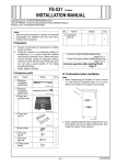
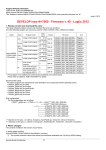
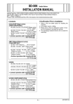
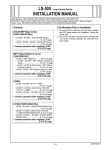
FS-612 Finisher
INSTALLATION MANUAL corretto
Applied Machine: C8000/C7000/C7000P/C6000/C70hc
COLOR PRESS: 80/(71ppm/71ppm)/(70ppm/70ppm)/(60ppm/60ppm)
Product Code: A1RF/A1DU/A204/A1DV/A205
No.
Note:
Take the same procedures, though the machine
photographs are different from the ones illustrated in the procedures.
Name
Shape
Q’ty
8. Rear end
stopper
1
15JMIXC008SA
I.Precaution
9. Knob screw
1. Choose a horizontal and stable floor for installing
the machine.
2. Lifting the machine in an awkward position or
transporting it in a poorly balanced position could
result in personal injury. When transporting the
machine, assign an adequate number of persons
to the job and ensure that each person can take a
good position of not being excessively loaded.
(mass: approx. 65 kg)
2
10. TP screw
M4x6
4
11. TP screw
M4x18
2
12. Truss screw
M4x8
2
13. Installation
manual
1
II.Accessory parts
No.
Name
Shape
Q’ty
1. Installation
plate/lower
• FS-612 + RU-508 + C8000........pages 3 to 4
• FS-612 + C7000/C7000PC/6000/C70hc
...................................................pages 4 to 5
• FS-612 + RU-509 + C7000/C7000P/C6000/C70hc
....................................................pages 6
1
A1TVIXC001CA
2. Installation
plate/upper
•Common operations after installing FS-612
. . . . . . . . . . . . . . . . . . Page 7 to 10
1
A1TVIXC002CA
3. Paper exit
up-down tray
III. Confirmation before installation
Note:
1. When transporting the Finisher, be sure to move
it in the direction illustrated below so as not to
deform the casters on the paper exit tray side.
1
A1TVIXC003CA
4. Paper exit
tray /1
1
OK
15JMIXC004SA
5. Paper exit tray/
lower
1
NG
15JMIXC005SA
6. Stopper block
1
15JMIXC006SA
15JMIXC009SA
7. Guide axis
2. When installing optional Post Inserter/Punch kit to
the Finisher, be sure to install it beforehand, then
install the finisher to the machine.
2
15JMIXC007SA
E-1
A1TV955022
IV.Procedure before installation
5. Pull out the stacker, then remove the locking
tape. Remove the guide tape from inside the
stacker (on the right side), and remove the locking material. (1 screw)
1. Visually inspect the Finisher.
2. Remove the locking tapes and the locking protection materials from the front door and the left side
of the Finisher.
Locking tape
Guide tape
Locking protection
materials
Locking tapes
Locking material
15SJIXE008SA
6. Remove the guide tape from inside the stacker
(on the left side), and remove the locking material (1 screw) and the locking tape (1 place) from
the staple cartridge (front).
Locking material
Guide tape
Locking tapes
15SJIXE006SB
Locking tape
3. Remove the locking tapes from each guide plates.
4. Remove the stacker locking materials.
15SJIXE009SB
7. Remove locking materials (2 places) from the
staple cartridge (back).
Note:
Remove the screw first.
Guide tapes
Screw
Screw
Four pieces of
locking tapes
Four pieces of
locking
materials
Locking materials
15SJIXE007SB
15JMIXE009SA
E-2
V.Installation procedure
8. When using paper in inch size (LT) or 16K.
(1) Loosen the three-fold stopper screw.
(2) Align the three-fold stopper to the mark for the
LT paper size on the right side.
Note:
For 16K paper size, align the sheet-metal level difference (located in the left) to the mark for the 16K
paper size.
Installation procedure for
[FS-612 + RU-508 + C8000]
1. Turn the Sub and Main power switches OFF, and
unplug the power cord from the outlet.
2. Install the machine installation plate (lower) on the
lower left side of RU-508. (TP screw M4x6: 2 pcs.)
Installation plate /Lw
Three-fold stopper
screw
TP screws M4x6
15JMIXE010SA
LT
A4
A1TVIXC004CA
Adjustment mark guides
The level difference
of sheet metal
3. Install the machine installation plate (upper) on the
upper left side of the RU-508. (TP screw M4x6: 2
pcs.)
Installation plate /Up
TP screws M4x6
A1TVIXC005CA
4. Connect the four connectors of the Finisher to
the connectors on the rear left side cover of the
RU-508.
Note:
Do not connect to the 8-pin connector.
Connectors of
RU side
Connectors of
Finisher side
8-pin connector
Not used
A1TVIXC006CA
E-3
5. Install the Finisher on the RU-508.
(1) Fit the hooks on the RU-508 installation plates
(upper and lower) into the upper and lower
holes on the Finisher as illustrated below, then
lock them by pushing the Finisher to the back.
Installation procedure for
[FS-612 + C7000/C7000P/C6000/C70hc]
1. Turn the Sub and Main power switches OFF, and
unplug the power cord from the outlet.
2. Remove the two caps on the left side cover of the
machine.
3. Remove the connector cover on the left side cover
of the machine. (1 screw)
Upper view
installation
plates/Up
Finisher
RU
Lower view
Connector cover
installation
plates/Lw
Caps
A2A4IXC002CA
A1TVIXC007CA
4. Install the machine installation plate (lower) on the
lower left side of machine. (TP screw M4x6: 2 pcs.)
Note:
If the gap between Finisher and RU-508 is not
equal from the top through the bottom, adjust it by
the height of the front and rear casters on the
paper exit side of the Finisher.
Machine installation plate (lower)
15JMIXE013SA
TP screws M4x6
Ԙ
Ԛ
ԙ
ԙ
A2A4IXC003CA
5. Install the machine installation plate (upper) on
the upper left side of the machine. (TP screw
M4x18: 2 pcs.)
Inclination
adjustment
(2) Fix the Finisher to the RU-508. (Knob screw: 2 pcs.)
Machine installation plate (upper)
TP screws M4x18
Knob screw
A2A4IXC004CA
A1TVIXC008CA
E-4
11. Connect the three connectors of the Finisher to
the connectors on the rear left side cover of the
machine. (1 connector is not used)
6. Remove the rear cover of the FS-612.
(6 screws)
Machine
connectors
Rear cover
not used
A1TVIXC013CA
7. Remove the CN-3 connector from the control
board as shown in the figure below.
8. Remove the short connector from the clamp.
OK
A2A4IXC005CA
12. Install the Finisher on the machine.
(1) Fit the hooks on the machine installation plates
(upper and lower) into the upper and lower
holes on the Finisher as illustrated below, then
lock them by pushing the Finisher to the back.
CN-3
Upper view
Finisher
Machine
Short connector
A1TVIXC015CA
9. Connect the short connector to the CN-3.
Note:
Unless the short connector is connected, the ISW
cannot be performed.
Lower view
Machine
Finisher
Short connector
A2A4IXC006CA
A04DIXE004SA
A04DIXJ004SA
(2) Fix the Finisher to the mac hine. (Knob screw: 2 pcs.)
A1TVIXC016CA
Knob screw
10.Reinstall the rear cover of the FS-612. (6 screws)
A2A4IXC007CA
E-5
5. Install the Finisher on the RU-509.
(1) Fit the hooks on the RU-509 installation plates
(upper and lower) into the upper and lower
holes on the Finisher as illustrated below, then
lock them by pushing the Finisher to the back.
Installation procedure for
[FS-612 + RU-509 + C7000/C7000P/C6000/C70hc]
1. Turn the Sub and Main power switches OFF, and
unplug the power cord from the outlet.
2. Install the machine installation plate (lower) on the
lower left side of RU-509. (TP screw M4x6: 2 pcs.)
Upper view
installation
plates/Up
Finisher
RU
Installation plate /Lw
Lower view
installation
plates/Lw
TP screws M4x6
A1TVIXC004CA
3. Install the machine installation plate (upper) on the
upper left side of the RU-509. (TP screw M4x6: 2
pcs.)
A1TVIXC010CA
Note:
If the gap between Finisher and RU-509 is not
equal from the top through the bottom, adjust it by
the height of the front and rear casters on the
paper exit side of the Finisher.
Installation plate /Up
15JMIXE013SA
TP screws M4x6
Ԙ
Ԛ
ԙ
A1TVIXC009CA
4. Connect the four connectors of the Finisher to
the connectors on the rear left side cover of the
RU-509.
Note:
Do not connect to the 8-pin connector.
ԙ
Inclination
adjustment
(2) Fix the Finisher to the RU-509. (Knob screw: 2 pcs.)
Connectors of
RU side
Connectors of
Finisher side
Knob screws
8-pin connector
Not used
A1TVIXC008CA
A1TVIXC006CA
E-6
VI.Common operations
(2) Insert the stopper block into the paper exit tray
/ lower.
(3) Use the screws from the lower up-down portion
to install the paper exit tray / lower.
(4) Insert the Guide axes on the paper exit tray /
lower.
(5) Insert the rear end stopper to the position of
the paper size to be used.
Note:
When installing the paper exit tray/lower, adjust
the height of the paper exit tray/lower using the
stopper block and secure the tray.
1. Insert paper exit tray/1 into the sub tray paper
exit slot on the Finisher.
Note:
When installing paper exit tray/1, push the tray all
the way in until you hear a click.
Paper exit tray/1
Guide axes
Paper exit
tray/ lower
15JMIXE015SA
2. Install the paper exit tray/lower on the lower up
down portion on the Finisher.
(1) Remove the 2 screws from the lower up-down
portion.
Screw
Screw
Stopper block
15JMIXE017SB
Rear end stopper
B4/8.5x14/8K
Adjustable in
three gradations
Screws
3. Install the paper exit up-down tray on the up
down portion on the Finisher.
(Truss screw M4x8: 2 pcs.)
Note:
When installing the paper exit up-down tray, hook
the paper exit up-down tray to the four auxiliary
metal hooks and secure the tray.
15JMIXE016SB
Paper exit up-down tray
Truss screws M4x8
E-7
15SJIXE013SA
VII. Importing FS Adjustment Data
Standard value
* For each paper size, the fold slippage should be
within 1 mm.
Import the factory adjustment data of the FS-612 to
the machine memory.
Step
1. Plug the power cord into the outlet and turn
ON the Main power switch.
2. Enter Service mode.
Note:
Refer to procedures in the Service Manual to
enter into the Service Mode.
Exit direction
.0mm
Under 1
15JMIXE019SA
b. Saddle Stitcher Stopper adjustment
If the copies are not stapled at the position adjusted
in step a, perform the following adjustment.
[Adjustment]
3. On the Service mode menu screen, touch
“Finisher Adjustment”.
4. [Finisher Adjustment Menu screen]
Touch “Recall Standard Data”.
Step
5. Touch “Factory Initial Data” on the recall
standard data screen and touch “Yes” .
1. [Finisher Adjustment menu screen]
Touch “Saddle Stitcher Stopper”.
6. Touch “Return” to return to the [Finisher
Adjustment Menu] screen.
2. Check the amount of gap on the rear edge of
the saddle-stitched sample copy.
• Touch “Print Mode” to go to the copy
screen.
• Make a saddle-stitched sample copy of
the size to be adjusted.
VIII.Confirmation of operation
1. Place the original in each mode setting in the
ADF.
2. Execute printing in Finisher mode to check the
condition of half-folding, center stapling, three
folding, and flat stapling.
Note:
If each mode setting is not appropriate value, execute the adjustment as following procedure.
3. Touch “Exit PrintMode” to return to the [Fold
& Staple Stopper adjustment] screen.
4. Select the size to be adjusted.
5. Use the numerical keys on the screen to enter
adjusting values (appropriate values), and
touch “Set”.
(Setting range: -128 to +127, 1 step=0.1mm)
a. Half-Fold Position adjustment
6. Make another sample copy.
[Adjustment]
7. Repeat steps 2 to 7 until the Center Staple
position is appropriate.
Step
1. [Finisher Adjustment menu screen]
Touch “Half-Fold Stopper Adj.”.
8. Repeat the same operation about other sizes.
9. Touch “Return” to return to the [Finisher
Adjustment Menu] screen.
2. Check the amount of gap on the rear edge of
the folded sample copy.
• Touch “Print Mode” to go to the copy
screen.
• Make a folded sample copy of the size to
be adjusted.
Standard value
* For each paper size, the slippage between fold
and staple should be within 1 mm.
3. Touch “Exit PrintMode” to return to the [Half
Fold Stopper Adj.] screen.
4. Select the adjustment object size.
5. Use the numerical keys on the screen to
enter adjusting values (appropriate values),
and touch “Set”.
(Setting range: -128 to +127, 1 step=0.1mm)
6. Make another sample copy.
7. Repeat steps 2 to 7 until the Half-Fold position is appropriate.
8. Repeat the same operation about other sizes.
9. Touch “Return” to return to the [Finisher Adjustment Menu] screen.
E-8
c. Tri-Fold Position adjustment
standard values
A4S and 8.5 x 11S and 16KS sizes
[Software adjustment]
First folding position adjustment (Standard value a)
Unit: mm
Normal value
Section
Step
Fold position
1. [Finisher Adjustment menu screen]
Touch “Tri-Fold Adjustment”.
2. Check the amount of gap on the rear edge of
the saddle-stitched sample copy.
• Touch “Print Mode” to go to the copy
screen.
• Make a tri-folded sample copy of the
size to be adjusted.
Item
Standard
A4S
8.5x11S
16KS
a
95
89.4
88
b
101
95
91
c
101
95
91
±2
d. 2 Position Staple adjustment
(Staple / Fold & Staple)
This is to be adjusted only after all the other adjustments have been completed.
1. 2 position staple pitch
[Adjustment]
3. Touch “Exit PrintMode” to return to the [TriFold Adjustment] screen.
Step
4. Select the size to be adjusted.
1. [2 position Staple Pitch screen]
Touch “Staple”.
5. Use the numerical keys on the screen to
enter adjusting values (appropriate values),
and touch “Set”.
(Setting range: -128 to +127, 1 step=0.1mm)
2. Touch “Print Mode”, make a stapled sample
copy on the copy screen, and check the staple pitch.
6. Make another sample copy.
3. If the staple pitch is not appropriate, touch
“Exit PrintMode” to return to the adjustment
screen, use the numerical keys on the
screen to enter adjusting values (appropriate
values), and touch “Set”.
(Setting range: 128 to 160, 1 Step=1mm)
7. Repeat steps 2 to 7 until the first folding
position a is appropriate.
8. Repeat the same operation about other sizes.
9. Touch “Return” to return to the [Finisher Adjustment Menu] screen.
4. Make another sample copy.
[Mechanical adjustment]
5. Repeat steps 3 to 5 until the staple pitch is
appropriate.
Second folding position adjustment (Standard value c)
When adjustment of the first folding position is finished, check the second folding position. If it is not
appropriate, adjust the location of three-fold stopper in the stacker.
Adjustment values
* Staple pitch A can be adjusted between 128 mm
and 160 mm.
A
Three-fold stopper
guide board
Three-fold stopper screw
LT
A4
16K
The level difference
of sheet metal
15JMIXC010SA
Adjustment mark guides
15JMIXE020SA
Second fold
First fold
a
c
b
15JMIXE021SA
E-9
X.Serial Number Registration
2. Fold and staple pitch
[Adjustment]
Register the serial number of the FS-612 to the
machine memory.
Step
Step
1. [2 Pos. Staple Pitch Adjustment screen]
Touch “Fold & Staple”.
1. Plug the power cord into the outlet and turn
ON the Main power switch.
2. Touch “Print Mode”, make a stapled and
folded sample copy on the copy screen, and
check the staple pitch.
2. Enter Service mode.
Note:
Refer to procedures in the Service Manual to
enter into the Service Mode.
3. If the staple pitch is not appropriate, touch
“Exit PrintMode” to return to the adjustment
screen, use the numerical keys on the
screen to enter adjusting values (appropriate
values), and touch “Set”.
(Setting range: 128 to 160, 1 step=1mm)
3. Touch the “System Setting” key.
4. Touch the “Serial Number Setting” key.
5. Touch the “Finisher” key to display the serial
number setting screen. (Select the installation order key.)
4. Repeat steps 2 to 4 until the staple pitch is
appropriate.
5. Make another sample copy.
6. Touch "Return" key and "Close" key.
Adjustment values
* Staple pitch A can be adjusted between 128 mm
and 160 mm.
A
15SJIXC014SA
IX. Adjustment Data Backup
If the FS-612 adjustment data is changed, back up
the main body finisher data to the FS-612 memory.
Step
1. On the Service mode menu screen, touch
“State Confirmation”.
2. Touch “I/O Check Mode”.
3. Enter “9” and “0” using the quantity setting
buttons. Make sure that <90-00> appears on
the message display.
4. Press the [Start] key.
Make sure that <OUT:FIN> appears on the
message display after the adjustment.
5. Touch the "Return" key, then touch the "Exit"
key.
E-10
6. Enter the serial number of the FS-612 and
touch the “OK” key. (Use “Shift” to switch
between upper case letters and lower case
letters.)
7. Touch the “Return” key, then touch the
"Close" key.