1
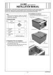
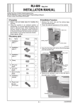
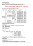
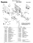
FS-531 Finisher
INSTALLATION MANUAL
Applied Machine: C7000/C7000P/C6000/C70hc
COLOR PRESS: (71ppm/71ppm)/(70ppm/70ppm)/(60ppm/60ppm)
Product Cord: A1DU/A204/A1DV/A205
No.
Note:
Take the same procedures, though the machine
photographs are different from the ones illustrated in the procedures.
Name
Shape
Q’ty
9. Installation
manual
1
I.Precaution
1. Choose a horizontal and stable floor for installing the machine.
2. Lifting the machine in an awkward position or
transporting it in a poorly balanced position
could result in personal injury. When transporting the machine, assign an adequate number
of persons to the job and ensure that each person can take a good position of not being
excessively loaded.
(mass: approx. 56.6 kg)
• FS-531+C7000/C7000P/C6000/C70hc
.................................................pages 3 to 4
• FS-531+RU-509+C7000/C7000P/C6000/C70hc
.................................................. .pages 4 to 5
•Common operations after installing FS-531
. . . . . . . . . . . . . . . . . . . . . . . Page 5
II.Accessory parts
No.
Name
III. Confirmation before installation
Shape
Q’ty
1. Machine
installation
plate/lower
Note:
1. When transporting the Finisher, be sure to move
it in the direction illustrated below so as not to
deform the casters on the paper exit tray side.
1
A2A4IXC001CA
2. Machine
installation
plate/upper
1
A04DIXC002SA
3. Paper exit
up-down tray
OK
1
NG
15JMIXC003SA
4. Paper exit
tray /1
1
15JKIXC001SA
2. When installing optional Post Inserter/Punch kit to
the Finisher, be sure to install it beforehand, then
install the finisher to the machine.
15JMIXC004SA
5. Knob screw
2
6. TP screw
M4x6
4
7. TP screw
M4x18
2
8. Truss screw
M4x8
2
E-1
A2A4955000
IV.Procedure before installation
4. Remove the locking tapes from each guide plates.
5. Remove the stacker locking materials.
1. Install the machine installation plate (upper) on the
upper left side of the machine. (TP screw M4x18: 2
pcs.)
locking
tapes
Machine installation plate (upper)
TP screws M4x18
Three
pieces of
locking
materials
A2A4IXC004CA
2. Visually inspect the Finisher.
3. Remove the locking tapes and the locking protection materials from the front door and the left side
of the Finisher.
15SFIXE002SA
Locking tapes
6. Pull out the stacker, then remove the locking
tapes, and remove the locking materials from
inside the stacker.
Locking
protection
materials
Locking tapes
Desiccating
agent
Locking
materials
15JKIXE002SA
Locking tapes
15SFIXE001SA
Locking tapes
E-2
V. Installation procedure
6. Install the Finisher on the machine.
(1) Fit the hooks on the machine installation plates
(upper and lower) into the upper and lower
holes on the Finisher as illustrated below, then
lock them by pushing the Finisher to the back.
Installation procedure for
[FS-531 + C7000/C7000P/C6000/C70hc]
1. Turn the Sub and Main power switches OFF, and
unplug the power cord from the outlet.
2. Remove the two caps on the left side cover of the
machine.
3. Remove the connector cover on the left side cover
of the machine. (1 screw)
Upper view
Machine
Finisher
Connector cover
Lower view
Machine
Finisher
Caps
A2A4IXC002CA
4. Install the machine installation plate (lower) on the
lower left side of machine. (TP screw M4x6: 2 pcs.)
A04DIXJ004SA
Note:
If the gap between Finisher and machine is not
equal from the top through the bottom or the position of the two screw holes are not aligned, adjust
those by the height of the front and rear casters on
the paper exit side of the Finisher.
Machine installation plate (lower)
TP screws M4x6
A2A4IXC003CA
5. Connect the three connectors of the Finisher to
the connectors on the rear left side cover of the
machine. (1 connector is not used)
15JKIXE003SA
Ԙ
ԙ
Machine
connectors
Not used
A2A4IXC005CA
E-3
Ԛ
ԙ
Inclination
adjustment
(2) Fix the Finisher to the mac hine. (Knob screw: 2 pcs.)
Installation procedure for
[FS-531 + RU-509 + C7000/C7000P/C6000/C70hc]
1. Turn the Sub and Main power switches OFF, and
unplug the power cord from the outlet.
2. Install the machine installation plate (lower) on the
lower left side of RU-509. (TP screw M4x6: 2 pcs.)
Knob screw
Installation plate /Lw
A2A4IXC007CA
TP screws M4x6
A1TVIXC004CA
3. Install the machine installation plate (upper) on the
upper left side of the RU-509. (TP screw M4x6: 2
pcs.)
Installation plate /Up
TP screws M4x6
A1TVIXC009CA
4. Connect the four connectors of the Finisher to
the connectors on the rear left side cover of the
RU-509.
Note:
Do not connect to the 8-pin connector.
Connectors of
RU side
Connectors of
Finisher side
8-pin connector
Not used
A1TVIXC006CA
E-4
VI.Common operations
5. Install the Finisher on the RU-509.
(1) Fit the hooks on the RU-509 installation plates
(upper and lower) into the upper and lower
holes on the Finisher as illustrated below, then
lock them by pushing the Finisher to the back.
1. Insert the paper exit tray/1 into the sub tray
paper exit slot on the Finisher.
Note:
When installing the paper exit tray/1, push the tray
all the way in until you hear a click.
Upper view
Paper exit tray/1
installation
plates/Up
Finisher
RU
Lower view
installation
plates/Lw
15JMIXE015SA
2. Install the paper exit up-down tray on the up
down portion on the Finisher.
(Truss screw M4x8: 2 pcs.)
Note:
When installing the paper exit up-down tray, hook
the paper exit up-down tray to the four auxiliary
metal hooks and secure the tray.
A1TVIXC010CA
Note:
If the gap between Finisher and RU-509 is not
equal from the top through the bottom, adjust it by
the height of the front and rear casters on the
paper exit side of the Finisher.
15JKIXE003SA
Ԙ
Ԛ
ԙ
ԙ
Inclination
adjustment
Paper exit up-down tray
Truss screws M4x8
15SJIXE013SA
VII.Confirmation of operation
(2) Fix the Finisher to the RU-509. (Knob screw: 2 pcs.)
1. Turn ON the Main and Sub power switches.
2. Execute the printing in the Sort mode to check if
it operated correctly.
3. Execute the printing in the Staple mode to check
if it stapled correctly.
Knob screws
A1TVIXC008CA
E-5