1
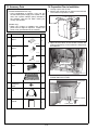
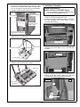
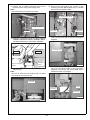
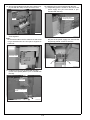
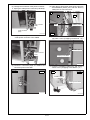
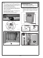
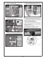
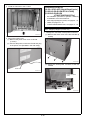
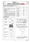
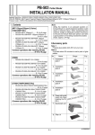
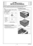
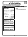
LS-505 Large Capacity Stacker
INSTALLATION MANUAL
Applied Machine: C6501/C6501P/C65hc/C8000/C7000/C7000P/C6000/C70hc/1200/1200P/1051
COLOR MFP: 65ppm COLOR PRESS:80/(71ppm/71ppm)/(70ppm/70ppm)/(60ppm/60ppm) MFP:120ppm/105ppm-2
Product Code: A0U0/A0U2/A0Y8/A1RF/A1UD/A204/A1DV/A205/A0G6/A0GA/A0G9
I.Contents
II.Confirmation Prior to Installation
1. Be sure that the machine’s Sub and Main switches
are OFF before starting the installation. Unplug the
power cord.
2. Do not turn the Main and Sub power switches ON
until all the locking materials are removed from
the LS-505.
[COLOR MFP 65ppm series]
[C6501/C6501P/C65hc]
•LS-505 + RU-504 + COLOR MFP 65ppm,
..................................................E-3 to 7 page
• LS-505 + FD-503 + RU-504 + COLOR MFP 65ppm
..................................................E-19 to 22 page
• Common operations after installing LS-505
.................................................E-22 to 23 page
[MFP 120ppm(105ppm-2) series]
[1200/1200P/1051]
•LS-505 + MFP 105ppm-2...........E-8 to 10 page
• LS-505 + RU-506 + MFP 120ppm (105ppm-2)
series....................................E-10 to 12 page
• LS-505 + LS-505 (2 attachments) + MFP 120ppm
(105ppm-2) series......................E-16 to 19 Page
• LS-505 + FD-503 + MFP 120ppm (105ppm-2) series
.......................................................E-19 to 22 page
• Common operations after installing LS-505
.................................................E-22 to 23 page
[C8000]
•LS-505 + RU-508 + EF-101 + C8000
.................................................E-12 to 14 page
•LS-505 + LS-505 (2 attachments) +RU-508
+ EF-101 + C8000....................E-16 to 19 page
•LS-505 + FD-503 + RU-508 + EF-101 + C8000
................................................E-19 to 22 page
• Common operations after installing LS-505
.................................................E-22 to 23 page
[C7000/C7000P/C6000/C70hc]
• LS-505 + RU-509 + C7000/C7000P/C6000/C70hc
..................................................E-14 to 16 page
• LS-505 + LS-505 (2 attachments) +RU-509
+ C7000/C7000P/C6000/C70hc..E-16 to 19 page
•LS-505 + FD-503 + RU-509 + C7000/C7000P/
C6000/C70hc...........................E-19 to 22 page
• Common operations after installing LS-505
...................................................E-22 to 23 page
E-1
A0H1955011
III. Accessory Parts
IV. Preparation Prior to Installation
Note:
(C7000/C7000P/C6000/C70hc only)
• In the combination of machine + RU +LS, the
LS-505 needs power supply from outside. In this
case, use a power code(for option) included in
the machine. Use the one which meets your
country specification.
1. Visually inspect the LS-505.
2. Remove the locking tape on the front door and the
cover sheet on top of the LS-505.
Cover sheet
(C8000 only)
• When the LS-505 is installed, the external
power source might be required. Prepare the
power cord. (Not bundled in the LS-505)
No.
Name
Shape
Locking tapes
Q’ty
1. Installation
plate/1
2
15ATIXC005SB
3. Open the front door of the LS-505, remove the
locking materials (4) on the handcart, and pull out
the handcart.
15ATIXC002SA
2. Installation
plate/2
2
15ATIXC003SA
3. Installation
plate/3
1
15ATIXC004SA
Locking materials
4. Connector
cover
1
15ATIXC005SA
5. Stacker tray
A0H1IXC001CA
4. Remove the locking tapes and the protection
material within the LS-505.
1
Locking tapes
15ATIXC006SA
6. S-tapping screw
(Hexagon)
M4x8
10
7. Relay power
cord
Locking tapes
1
8. Installation
manual
Protection material
1
Locking tapes
E-2
15ATIXC007SC
V. Installation Procedure
5. Remove the locking tape and the protection material from the connector and casters, and the notice
on how to bring the machine down onto the floor.
(Casters are also at both sides in front.)
Installation procedure for
[LS-505 + RU-504 + COLOR MFP 65ppm]
*
Protection material
Locking tapes
●●●●●●
●●●
●●●●●●
●
●●●●●●
●●●
●●●●●●
●●
●●●●●●
●
For the installation procedure for the RU-504,
see the RU-504 installation manual.
1. Turn OFF the machine's Sub and Main power
switches, and unplug the power cord.
2. Install the machine installation plate/L (included in
the RU package) (TP screw M4x6: 4 pcs.:
included with the RU).
Caster locking
tape (also at both
sides in front)
Machine installation plate/L
Notice on how to bring the
machine down onto the floor
15ATIXC009CB
6. Remove the locking tapes and the protection
materials from the handcart.
TP screws M4x6
15ATIXE027SA
Protection materials
3. Install the blindfold plate (included in the RU
package) (TP screw M4x6: 2 pcs.: included with
the RU).
Locking tapes
Blindfold plate
Locking tapes
A0H1IXC002CA
7. Align the stacker tray included in the package to
the pins of the handcart, and install it.
Stacker tray
TP screws M4x6
15ATIXE028SA
4. Align the bottom hole of the LS-505 with the positioning pin on the power supply unit, and lock
them by sliding the LS-505 toward the back.
LS-505
Align to pins
of the handcart
RU
Pin
A0H1IXC003CA
Hole position
15ATIXE029SB
E-3
5. Open the front door of the LS-505, and install
installation plate/3. (S-tapping screw M4x8:1 pc.)
6. Install the reinforcing plate/R (included in the RU
package) on the back of machine installation
plate/R and machine installation plate/L. (TP
screw M4x6: 4 pcs.: included with the RU)
Reinforcing
plate/R
Install installation plate/3
S-tapping screw M4x8
TP screws M4x6
TP screws
M4x6
15ATIXE045SA
Note:
In case those screw holes height do not match to
fix the installation plate/3 by screw, adjust the
height of LS-505 casters (4 parts) to mach those
screw holes.
Every caster has ratchet mechanism.
It goes up with reciprocating the driver into the
whole 1, and it goes down with reciprocating the
driver into the whole 2.
Be sure not to go it up too much, otherwise the bolt
would come off. (max. ±5mm)
(Be sure the caster is contacting installation surface, otherwise the ratchet will not work.)
15AQIXE050SB
7. Retract the supporting leg on the back side of the
power supply unit.
15AQIXC008SA
8. Unplug the connector shown in the photograph
from the LS-505.
Connector jack
Driver sockets
Skew adjustment
15ATIXE001CB
15ATIXE047SA
E-4
9. Connect the 4 LS-505 connector plugs to the
connector jacks of the power supply unit.
Note:
Not used pointed connectors by arrows.
12. Pull out the conveyance unit, secure it with
screws (TP screw (black) M3x8: 2pcs.: included
with the RU), and push it back.
TP screws (black) M3x8
LS-505 connectors
Option side
Not used
Machine side
15AQIXE054SB
13. Loosen 2 screws, and remove the connector
cover on the back side of the RU conveyance
segment.
A0H1IXC015CA
10. Place the conveyance unit on the rail of machine
installation plate/R and machine installation plate/L,
and slide it all the way in until it stops at the back.
Conveyance unit
Connector cover
Machine
Option
Machine
installation
plate/L
Machine installation
plate/R
15AQIXE055SA
14. Connect 2 connector plugs of the power supply
unit to the connector plugs of the conveyance
segment, and secure the wire bundle with 2
clamps as shown in the figure.
15AQIXE052SA
11. Remove the lock shaft of the conveyance unit (1
black screw).
Note:
Be sure to store the lock shaft for the use when
removing the conveyance unit.
Lock shaft
Power supply
connectors
Clamps
Wire bundle
15AQIXE056SA
15AQIXE053SA
E-5
18. Install the front cover (included with the RU).
(1) Temporarily place 2 screws in the front of the
power supply unit (TP screw M4x6: 2 pcs.:
included with the RU).
15. Secure the bundled connectors of the power supply unit with the clamp on the connector cover.
TP screws M4x6
(temporarily secured)
Clamp
15AQIXE057SA
00AAIXE000SA
16. Install the connector cover on the RU conveyance segment.
Note:
Fit the wire bundle in the RU machine so that it will
not get hooked when the conveyance segment is
pulled out.
15AQIXE001CA
(2) Align the bottom holes of the front cover with
the pins of the power supply unit, and use the
temporarily placed screws to secure it.
Connector cover
Pin
Pin
15AQIXE061SA
15AQIXE058SA
17. Install the back cover (included with the RU)
(Truss screw (black) M4x6: 2 pcs.: included with
the RU).
Back cover
Truss screws (black)
M4x6
15ATIXE031SA
E-6
Note:
If the front cover does not close because it touches
the machine or optional unit, adjust the horizontal
position or angle of the front cover. If the actuator
does not turn the interlock switch ON, adjust the
position of the actuator adjustment plate as well.
21. Plug in the power cord.
(1) Remove the power cord cover on the RU-504
and the LS-505. (2 screws)
(2) Connect the relay power cord included in the
package to the LS-505.
RU-504
LS-505
Loosen the screw to adjust the angle
Loosen the screw to
adjust the horizontal position
15ATIXE008CA
15AQIXF062SA
Actuator adjustment plate
Loosen the
screws to
adjust the
horizontal
position
19. Install the handcart to the LS-505.
15ATIXC001CA
20. Close the front door of the LS-505.
E-7
b. Plug in the inlet power connector and set the
outlet power connector in the saddle.
Installation procedure for
[LS-505 + MFP 105ppm-2]
1. Turn the machine’s Sub and Main power switches
OFF, and unplug the power cord.
2. Install the Installation plate/1 (2 places) and the
Installation plate/2 (2 places) on the left side of
the main body as below. (S-tapping screw M4x8:
8 pcs.)
Power connector
(inlet)
Saddle
A0H1IXC011CA
(2) Align the top and bottom holes of the LS-505 to
the Installation plate/1 pins, and lock them by
sliding the LS to the back.
Top
LS
Installation
plate/1
Main body
Installation
plate/2
S-tapping screws M4x8
Holes
S-tapping screws M4x8
Installation plate/ 1
A0H1IXC014CA
3. Install the LS-505 to the main body.
(1) Change the connection of the power connector.
a. Unplug the outlet power connector (red band).
Bottom
15ATIXE015SA
(3) Secure the LS-505 onto the Installation plate/2
(top) with a screw. (S-tapping screw M4x8: 1 pc.)
Installation plate/2
Power connector
(outlet)
S-tapping screws M4x8
Power connector
(inlet)
A0H1IXC010CA
A0H1IXC004CA
E-8
(4) Insert the Installation plate/3 pin, and secure it
with a screw. (S-tapping screw M4x8: 1 pc.)
(5) Remove the connector cover on the back of
the LS-505 (2 screws).
Connector cover
Installation plate/ 3
S-tapping screw M4x8
15ATIXE017SA
15ATIXE019SA
Note:
In case those screw holes height do not match to
fix the installation plate/2 and the installation plate/
3 by screw, adjust the height of LS-505 casters (4
parts) to mach those screw holes.
Every caster has ratchet mechanism.
It goes up with reciprocating the driver into the
whole 1, and it goes down with reciprocating the
driver into the whole 2.
Be sure not to go it up too much, otherwise the bolt
would come off. (max. ±5mm)
(Be sure the caster is contacting installation surface, otherwise the ratchet will not work.)
(6) Connect 4 connector plugs of the LS-505 to
the connector jacks on the machine.
LS-505 connector plugs
Not used
A0H1IXC006CA
(7) Use the screws removed in step (5) to install
the connector cover included in the package.
(Screw M3x6: 2 pcs.)
Driver sockets
Connector cover
Skew adjustment
Screws M3x6
15ATIXE001CB
15ATIXE021SA
E-9
4. Install the handcart to the LS-505.
Installation procedure for
[LS-505 + RU-506 + MFP 120ppm(105ppm-2) series]
* For the installation procedure for the RU-506,
see the RU-506 installation manual.
1. Install LS-505 to the combination of RU-506 and
the machine.
(1) Install the Installation plate/1 (2 places) and the
Installation plate/2 (2 places) on the left side of
RU-506 as below. (S-tapping screw M4x8:
8 pcs.)
A0H1IXC005CA
5. Close the front door of the LS-505.
Installation
plate/1
S-tapping screws M4x8
Installation
plate/2
S-tapping screws M4x8
A0H1IXC016CA
(2) Unplug the LS-505 connector shown in the
photograph.
Connector jack
LS-505
15ATIXC005CB
E-10
(3) Change the connection of the power connector.
a. Unplug the outlet power connector (red band).
(5) Align the top and bottom holes of the LS unit to
the Installation plate/1 pins, and lock them by
sliding the LS unit to the back.
Top
LS
Power connector
(outlet)
RU
Holes
Installation plate/1
Power connector
(inlet)
Bottom
A0H1IXC010CA
15ATIXC015SB
b. Plug in the inlet power connector and set the
outlet power connector in the saddle.
(6) Secure the LS-505 onto the Installation plate/2
(top) with a screw. (S-tapping screw M4x8: 1 pc.)
Installation plate /2
Power connector
(inlet)
S-tapping screw M4x8
Saddle
A0H1IXC011CA
A0H1IXC004CA
(4) Connect 5 connector plugs of LS-505 to the
connector jacks on RU-506.
RU-506
LS-505
(7) Insert the Installation plate/3 pin, and secure it
with a screw. (S-tapping screw M4x8: 1 pc.)
LS-505
RU-506
Installation plate /3
S-tapping screw M4x8
A0H1IXC007CA
15ATIXC007CB
E-11
Note:
In case those screw holes height do not match to
fix the installation plate/2 and the installation plate/
3 by screw, adjust the height of LS-505 casters (4
parts) to mach those screw holes.
Every caster has ratchet mechanism.
It goes up with reciprocating the driver into the
whole 1, and it goes down with reciprocating the
driver into the whole 2.
Be sure not to go it up too much, otherwise the bolt
would come off. (max. ±5mm)
(Be sure the caster is contacting installation surface, otherwise the ratchet will not work.)
Installation procedure for
[LS-505+RU-508+EF-101+C8000]
*
For the installation procedure for the RU-508,
see the RU-508 installation manual.
1. Install LS-505 to the combination of RU-508.
(1) Install the Installation plate/1 (2 places) and the
Installation plate/2 (2 places) on the left side of
RU-508 as below. (S-tapping screw M4x8: 8
pcs.)
Driver sockets
Skew adjustment
Installation
plate/1
S-tapping screws M4x8
15ATIXE001CB
Installation
plate/2
S-tapping screws M4x8
A0H1IXC018CA
2. Install the handcart to the LS-505.
(2) Unplug the LS-505 connector shown in the
photograph.
Connector jack
LS-505
15ATIXC001CA
15ATIXC005CB
3. Close the front door of the LS-505.
E-12
(6) Insert the Installation plate/3 pin, and secure it
with a screw. (S-tapping screw M4x8: 1 pc.)
(3) Connect 4 connector plugs of LS-505 to the
connector jacks on RU-508.
RU-508
Connector
LS-505
LS-505
Connector
RU-508
Installation plate /3
S-tapping screw M4x8
Not used
A0H1IXC019CA
A0H1IXC021CA
(4) Align the top and bottom holes of the LS unit to
the Installation plate/1 pins, and lock them by
sliding the LS unit to the back.
Top
LS
Holes
RU
Installation plate/1
Note:
In case those screw holes height do not match to
fix the installation plate/2 and the installation plate/
3 by screw, adjust the height of LS-505 casters (4
parts) to mach those screw holes.
Every caster has ratchet mechanism.
It goes up with reciprocating the driver into the
whole 1, and it goes down with reciprocating the
driver into the whole 2.
Be sure not to go it up too much, otherwise the bolt
would come off. (max. ±5mm)
(Be sure the caster is contacting installation surface, otherwise the ratchet will not work.)
Bottom
A0H1IXC020CA
(5) Secure the LS-505 onto the Installation plate/2
(top) with a screw. (S-tapping screw M4x8: 1 pc.)
Driver sockets
Installation plate /2
Skew adjustment
S-tapping screw M4x8
15ATIXE001CB
A0H1IXC004CA
E-13
2. Install the handcart to the LS-505.
Installation procedure for
[LS-505 + RU-509
+C7000/C7000P/C6000/C70hc]
*
For the installation procedure for the RU-509,
see the RU-509 installation manual.
1. Install LS-505 to the combination of RU-509.
(1) Install the Installation plate/1 (2 places) and the
Installation plate/2 (2 places) on the left side of
RU-509 as below. (S-tapping screw M4x8: 8
pcs.)
15ATIXC001CA
3. Close the front door of the LS-505.
4. Plug in the power cord.
(1) Remove the power cord cover of LS-505. (1
screw)
(2) Connect the power cord to the LS-505 and plug
in the power cord. (Prepare separately:Bundled
in the main body for some areas)
Installation
plate/1
S-tapping screws M4x8
Installation
plate/2
S-tapping screws M4x8
A0H1IXC018CA
(2) Unplug the LS-505 connector shown in the
photograph.
Power cord
A0H1IXC023CA
Connector jack
LS-505
15ATIXC005CB
E-14
(6) Insert the Installation plate/3 pin, and secure it
with a screw. (S-tapping screw M4x8: 1 pc.)
(3) Connect 4 connector plugs of LS-505 to the
connector jacks on RU-509.
RU-509
Connector
LS-505
LS-505
Connector
RU-509
Installation plate /3
S-tapping screw M4x8
Not used
A0H1IXC019CA
A0H1IXC021CA
(4) Align the top and bottom holes of the LS unit to
the Installation plate/1 pins, and lock them by
sliding the LS unit to the back.
Top
LS
Holes
RU
Installation plate/1
Note:
In case those screw holes height do not match to
fix the installation plate/2 and the installation plate/
3 by screw, adjust the height of LS-505 casters (4
parts) to mach those screw holes.
Every caster has ratchet mechanism.
It goes up with reciprocating the driver into the
whole 1, and it goes down with reciprocating the
driver into the whole 2.
Be sure not to go it up too much, otherwise the bolt
would come off. (max. ±5mm)
(Be sure the caster is contacting installation surface, otherwise the ratchet will not work.)
Bottom
A0H1IXC020CA
(5) Secure the LS-505 onto the Installation plate/2
(top) with a screw. (S-tapping screw M4x8: 1 pc.)
Driver sockets
Installation plate /2
Skew adjustment
S-tapping screw M4x8
15ATIXE001CB
A0H1IXC004CA
E-15
2. Install the handcart to the LS-505.
Installation procedure for
[LS-505 + LS-505 + MFP 120ppm(105ppm-2) series]
[LS-505+LS-505+RU-508+EF-101+C 8000]
[LS-505+LS-505+RU-509
+C7000/C7000P/C6000/C70hc]
* See Installation procedure for [LS-505 + Machine]
for installation of the first LS-505 unit.
• MFP 120ppm(105ppm-2) series, see pages 8 - 12.
• C8000, see pages 12 - 14.
• C7000/C7000P/C6000/C70hc, see pages 14 - 16.
MFP 120ppm(105ppm-2) series only
15ATIXC001CA
3. Close the front door of the LS-505.
4. Plug in the power cord.
(1) Remove the power cord cover of LS-505.
(1 screw)
(2) Connect the power cord to the LS-505 and plug
1. Change the connection of the power connector.
(1) Remove the back cover of the first LS-505. (6
screws)
in the power cord. (Bundled in the main body)
A0H1IXC012CA
(2) Unplug the outlet power connector of the first
LS-505.
Power cord
A0H1IXC023CA
Power connector
(inlet)
Power connector
(outlet)
A0H1IXC013CA
E-16
(3) Plug in the inlet power connector of the first
LS-505 and set the outlet power connector in
the saddle.
[MFP 120ppm(105ppm-2) series/C8000/C7000
/C7000P/C6000/C70hc] Common operations
1. Install the second LS-505 unit to the combination
of the LS-505.
(1) Install the Installation plate/1 (2 places) and the
Installation plate/2 (2 places) on the left side of the
first LS-505 as below. (S-tapping screw M4x8: 8 pcs.)
Saddle
Power connector
(inlet)
A0H1IXC017CA
(4) Unplug the outlet power connector (red band)
of the second LS-505.
Installation plate/ 1
Power connector
(outlet)
S-tapping screws M4x8
Installation plate/ 2
S-tapping screws M4x8
15ATIXE033SA
(2) Remove the connector cover on the left side of
the first LS-505 (1 screw).
Power connector
(inlet)
A0H1IXC010CA
(5) Plug in the inlet power connector of the second
LS-505 and set the outlet power connector in
the saddle.
Connector cover
15ATIXJ025SB
(3) Unplug the second LS-505 connector shown in
the photograph.
Power connector
(inlet)
Connector jack
Saddle
A0H1IXC011CA
Second LS-505
15ATIXC005CA
E-17
(7) Insert the Installation plate/3 pin, and secure it
with a screw. (S-tapping screw M4x8: 1 pc.)
(4) Connect the 5 connector plugs of the second
unit of the LS-505 to the connector jacks on
the first unit.
Second LS
LS-505
Installation plate /3
Second connector
plugs
S-tapping screw M4x8
15ATIXC007CA
A0H1IXC009CA
(5) Align the top and bottom holes of the second
LS unit to the Installation plate/1 pins, and lock
them by sliding the second LS to the back.
Top
Second LS
Holes
LS-505
Installation plate/1
Note:
In case those screw holes height do not match to
fix the installation plate/2 and the installation plate/
3 by screw, adjust the height of LS-505 casters (4
parts) to mach those screw holes.
Every caster has ratchet mechanism.
It goes up with reciprocating the driver into the
whole 1, and it goes down with reciprocating the
driver into the whole 2.
Be sure not to go it up too much, otherwise the bolt
would come off. (max. ±5mm)
(Be sure the caster is contacting installation surface, otherwise the ratchet will not work.)
Bottom
15ATIXC006CB
(6) Secure the LS-505 onto the Installation plate/2
(top) with a screw. (S-tapping screw M4x8: 1
pc.)
Second LS
LS-505
Driver sockets
Skew adjustment
Installation
plate /2
S-tapping screw M4x8
15ATIXE001CB
A0H1IXC004CA
E-18
2. Install the handcart to the LS-505.
Installation procedure for
[LS-505 + FD-503 + RU-504
+ COLOR MFP 65ppm series]
[LS-505 + FD-503
+ MFP 120ppm(105ppm-2) series]
[LS-505 + FD-503 +RU508+EF+101+ C8000]
[LS-505 + FD-503 +RU509
+ C7000/C7000P/C6000/C70hc]
* For the installation procedure for the RU-504/
508/509, see the RU-504/508/509 installation
manual.
A0H1IXC005CA
3. Close the front door of the LS-505.
4. Plug in the power cord.
(C8000/C7000/C7000P/C6000/C70hc only)
(1) Remove the covers of the 1st tandem and the
2nd tandem.
(2) Connect the power source connector.
1. Turn the machine’s Sub and Main switches OFF,
and unplug the power cord.
2. Install the Installation plate/1 (2 places) and the
Installation plate/2 (2 places) on the left side of
the FD-503 as below. (S-tapping screw M4x8: 8
pcs.)
Power cord
Installation plate/ 1
Installation plate/ 2
A0H1IXC024CA
S-tapping screws M4x8
S-tapping screws M4x8
15ATIXE039SA
3. Remove the connector cover on the left side of
the FD-503 (1 screw).
Connector cover
15ATIXE040SA
E-19
4. Remove the tray support plate (5 screws).
6. Install the LS-505 to the FD-503.
(1) Unplug the LS-505 connector shown in the
photograph.
Tray support plate
Connector jack
15ATIXE041SA
5. Change the connection of the power connector
on LS-505.
(In case of MFP 120ppm(105ppm-2) series)
(1) Unplug the outlet power connector (red band).
15ATIXE047SA
(2) Connect the connector plugs of the LS-505 to
the connector jacks on the FD-503.
a. In case of COLOR MFP 65ppm series/C8000/
C7000/C7000P/C6000/C70hc (4 connectors)
Note:
Not used pointed connectors by arrows.
FD-503
Power connector
(outlet)
LS-505
LS-505 connector
plugs
Power connector
(inlet)
A0H1IXC010CA
(2) Plug in the inlet power connector and set the
outlet power connector in the saddle.
Not used
15ATIXE004CB
b. In case of MFP 120ppm(105ppm-2) series
(5 connectors)
FD-503
LS-505
Power connector
(inlet)
LS-505 connector
plugs
Saddle
A0H1IXC011CA
A0H1IXC008CA
E-20
(3) Align the top and bottom holes of the LS-505 to
the Installation plate/1 pins, and lock them by
sliding the LS-505 to the back.
Top
LS-505
FD-503
Installation plate/ 1
Holes
Note:
In case those screw holes height do not match to
fix the installation plate/2 and the installation plate/
3 by screw, adjust the height of LS-505 casters (4
parts) to mach those screw holes.
Every caster has ratchet mechanism.
It goes up with reciprocating the driver into the
whole 1, and it goes down with reciprocating the
driver into the whole 2.
Be sure not to go it up too much, otherwise the bolt
would come off. (max. ±5mm)
(Be sure the caster is contacting installation surface, otherwise the ratchet will not work.)
Bottom
15ATIXE042SB
(4) Secure the LS-505 onto the Installation plate/2
(top) with a screw. (S-tapping screw M4x8: 1 pc.)
LS-505
FD-503
Driver sockets
Installation plate/ 2
Skew adjustment
S-tapping screw M4x8
15ATIXE001CB
15ATIXE005CA
(5) Insert the Installation plate/3 pin, and secure it
with a screw. (S-tapping screw M4x8: 1 pc.)
LS-505
7. Install the handcart to the LS-505.
FD-503
Installation plate/ 3
S-tapping screw M4x8
15ATIXE044SB
15ATIXC001CA
8. Close the front door of the LS-505.
E-21
9. Plug in the power cord.
(In case of COLOR MFP 65ppm series/C8000/
C7000/C7000P/C6000/C70hc)
(1) Remove the power cord cover on the FD-503
(1 screw) and the LS-505 (2 screws).
(2) Connect the relay power cord included in the
package to the FD-503 and the LS-505.
FD-503
VI. Serial Number Registration
Register the serial number of the LS-505 that has
been installed to the machine.
The location of the serial number is shown in the figure below.
LS-505
15ATIXC010SA
15ATIXE050SB
[COLOR MFP 65ppm series]
Step
1. Plug the power cord into the outlet and turn
ON the Main power switch.
2. Enter Service mode.
Note:
Refer to procedures in the Service Manual to
enter into the Service Mode.
3. [Service Mode Menu screen]
Touch “System Setting”.
4. [System Setting Menu screen]
Touch “M/C Serial Number Setting”.
5. Touch the finisher No. key according to the
place where it was installed to display the
Serial number entry screen.
* Machine + LS-505: Finisher 1
Machine + FD-503 + LS-505: Finisher 2
6. Enter the serial number of the LS-505 and
touch “OK”. (Use “Shift” to switch between
upper case letters and lower case letters.)
7. Touch “Return” on the serial number list
screen.
E-22
[MFP 120ppm (105ppm-2) series]
Step
1. Plug the power cord into the outlet and turn
ON the Main power switch.
2. Enter Service mode.
Note:
Refer to procedures in the Service Manual to
enter into the Service Mode.
3. Touch the “System Setting” key.
4. Touch the “M/C Serial Number Setting” key.
5. Touch the "Finisher" key to display the serial
number setting screen. (Select the installation
order key.)
6. Enter the serial number of the LS-505 and
touch the “OK” key. (Use the “Shift” key to
switch between upper case letters and lower
case letters.)
7. Touch the “OK” key on the serial number list
screen.
[C8000/C7000/C7000P/C6000/C70hc]
Step
1. Plug the power cord into the outlet and turn
ON the Main power switch.
2. Enter Service mode.
Note:
Refer to procedures in the Service Manual to
enter into the Service Mode.
3. Touch the “System Setting” key.
4. Touch the “Serial Number Setting” key.
5. Touch the "Finisher" key to display the serial
number setting screen. (Select the installation
order key.)
6. Enter the serial number of the LS-505 and
touch the “OK” key. (Use the “Shift” key to
switch between upper case letters and lower
case letters.)
7. Touch the “Return” key.
E-23