1
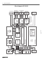
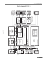
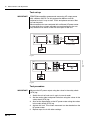
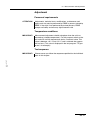
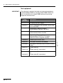
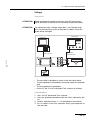
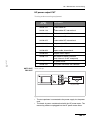
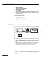
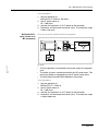
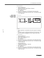
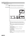
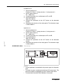
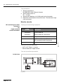
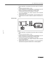
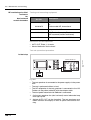
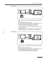
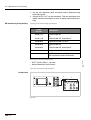
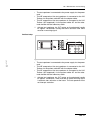
5 • Circuit Descriptions
CPU + Sensors
The "CPU + Sensors" circuit board includes the processor controlling
all the hardware assemblies in the HF unit, and with the software assemblies ensures the necessary exchange of data. All relevant sensors are also accommodated here.
Sensors
The HF-voltage sensor consists of a transformer which is directly connected to AE and NE on its primary side. The HF voltage supplied by
the generator is stepped down and passed to an active peak value
rectifier on the secondary side. The rectifier's output voltage is proportional to the HF peak voltage (UHFp). A relay can be used to switch
the sensitivity of the sensor to produce a measuring range up to 1000
V and a measuring range up to 4000 V.
The HF current sensor also consists of a transformer with a downstream peak value rectifier. This results in an output voltage which is
proportional to the HF peak voltage (IHFp). A measuring range up to
1 A and a measuring range up to 6.5 A then result for each relay
changeover.
The phase angle between the voltage and current is determined by
the phase sensor. A signal is derived on the secondary side of the
voltage transformer and current transformer and transmitted to an
evaluating circuit. This detects the corresponding zero crossings and
generates a DC voltage proportional to the phase angle.
Art.-Nr.: 80116-271
04.06
The size of the resulting spark is also measured. As a spark produced
when cutting biological tissue jumps more readily from the metal tip
of the electrode to the tissue and not vice versa, this creates a rectification effect, i.e., a direct current is superimposed on the HF current,
so resulting in a DC voltage at the output coupling capacitor in the HF
generator. This DC voltage can be measured with the spark sensor.
It is proportional to the size of the spark produced. The DC voltage is
chopped and transformed and rectified from the patient circuit to the
intermediate circuit by a transformer.
The HF output is calculated from the values for voltage, current and
phase.
Redundancies
The motherboard is equipped with another voltage sensor as redundancy for the voltage sensor, albeit with a lower precision level.
For the current sensor the measurements using NESSY 2 serve as
redundancy.
Control
The high-voltage power supply unit is provided with the necessary
parameters via the control inputs for the setpoint voltage and current
limitation. These may either be set, i.e. fixed, or regulated. Hardware
is used to ensure fast control. Depending on the type of control required, the analog output value of one of the sensors may directly affect the power supply unit voltage and thus also the resulting HF
voltage, bringing about voltage regulation, for example.
This entire system has a second slower control loop superimposed
on it, which is realized using software.
27 / 144