1
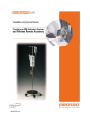
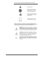
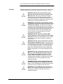
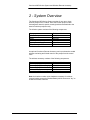
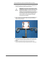
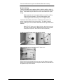
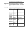
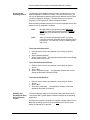
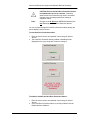
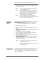
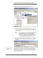
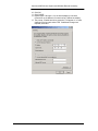
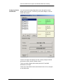
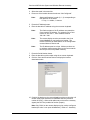
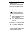
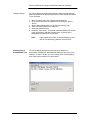
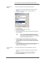
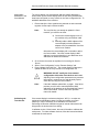
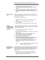
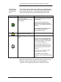
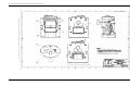
MATERIAL SPECIFICATION FOR DOCUMENT 205522
1
MATERIAL NUMBER
205522
2
MATERIAL TYPE/COLOR
2.1
COVERS:
8.5” X 11” 65 Lb. Grey speckletone. Cover – smooth finish.
2.2
INTERNAL PAGES
8.5” X 11” 50 Lb. White Opaque Paper, Offset.
11” X 17” 50 Lb. White Opaque Paper, Offset.
2.3
BINDING:
Unicoil Binding System, Color: College Orange, sized to match the document. Cover stock and
internal pages will be drilled to match the Unicoil configuration.
3
PRINT COLORS
3.1
FRONT COVER
The front cover will be single-sided, produced using xerographic methods from provided cameraready originals, or printed directly from provided electronic masters.
3.2
REAR COVER:
The rear cover will be left blank.
3.3
INTERNAL PAGES
Internal pages will be double-sided, produced using xerographic methods from provided singlesided camera-ready originals, or printed from provided electronic masters. All internal copies will
be black.
4
CERTIFICATION
Certification is not required; however, a packing list with the following information is required:
•
MEDRAD Material Number
•
Purchase Order Number
•
Quantity Shipped
205522 Rev B
Installation and Service Manual
205522 Rev B
i
North American Headquarters
MEDRAD, INC.
One Medrad Drive
Indianola, Pa 15051-0780
U.S.A
Phone: 412 767-2400
Fax: 412-767-4128
MEDRAD Europe B.V.
Postbus 205
6190 AE Beek
The Netherlands
Phone: +31(0)43-3585601
Fax: +31(0)43-3656598
Nihon MEDRAD KK
2-4-9, Umeda, Kita-ku,
Osaka, 530-0001
Japan
Phone: +81 (0) 66-133-6250
FAX: +81 (0) 66-344-2395
© 2008, MEDRAD Inc. All rights reserved.
Reproduction of this manual is strictly prohibited without express written consent of MEDRAD,
Inc.
For more information about MEDRAD products and services, please visit WWW.MEDRAD.COM.
ii
iii
TABLE OF CONTENTS
TABLE OF CONTENTS................................................................................................................. iv
1 - Introduction............................................................................................................................ 1-1
Using the Manual ..................................................................................................................... 1-1
Important Safety Notice............................................................................................................ 1-1
Trademarks .............................................................................................................................. 1-1
Disclaimers............................................................................................................................... 1-1
Understanding Symbols ........................................................................................................... 1-1
Warnings .................................................................................................................................. 1-4
Cautions ................................................................................................................................... 1-5
2 - System Overview................................................................................................................... 2-1
3 - System Installation................................................................................................................ 3-1
Installing an Infusion System without a Remote Accessory..................................................... 3-2
Installing an Infusion System with a Remote Accessory.......................................................... 3-2
Translation Materials and Instructions ..................................................................................... 3-4
4 - Pump Service......................................................................................................................... 4-1
Overview .................................................................................................................................. 4-1
Replacing an Infusion Pump .................................................................................................... 4-1
Installing or Replacing a Pump Battery .................................................................................... 4-1
Calibrating a Pump................................................................................................................... 4-1
Viewing the Infusion History..................................................................................................... 4-2
Troubleshooting........................................................................................................................ 4-2
Periodic Maintenance............................................................................................................... 4-3
5 - Bracket Service ..................................................................................................................... 5-1
Overview .................................................................................................................................. 5-1
Enabling Wireless on a Bracket ............................................................................................... 5-1
Installing or Replacing a Wireless Battery................................................................................ 5-1
Replacing a Wireless Bracket .................................................................................................. 5-2
Troubleshooting........................................................................................................................ 5-2
Periodic Maintenance............................................................................................................... 5-3
6 - Remote Display Service........................................................................................................ 6-1
Overview .................................................................................................................................. 6-1
Accessing the Service Screen ................................................................................................. 6-2
Accessing the Operating System ............................................................................................. 6-4
Enabling and Disabling the Hard Drive Protection Feature ..................................................... 6-4
Installing or Upgrading the Application Software ..................................................................... 6-6
Upgrading the OS and BIOS Software..................................................................................... 6-6
Viewing the Software Version .................................................................................................. 6-7
Configuring the Certo Network Settings for Wireless Operation.............................................. 6-7
Configure the SSID .............................................................................................................. 6-8
Configure the IP Addresses ................................................................................................. 6-9
Configuring Stands and Brackets........................................................................................... 6-12
iv
Adding a Stand .................................................................................................................. 6-13
Removing a Stand ............................................................................................................. 6-13
Adding a Bracket................................................................................................................ 6-13
Replacing a Bracket........................................................................................................... 6-16
Reconfiguring a Bracket..................................................................................................... 6-16
Removing a Bracket........................................................................................................... 6-16
Testing a Bracket ............................................................................................................... 6-17
Updating Certo’s Permitted MAC List .................................................................................... 6-17
Adding a Certo Module ...................................................................................................... 6-18
Removing a Certo Module ................................................................................................. 6-18
Adding MAC Addresses to the Certo Module .................................................................... 6-19
Calibrating the Touchscreen .................................................................................................. 6-19
Downloading Event Logs ....................................................................................................... 6-20
Copying Configuration Data to another Remote or saving the file as a back-up................... 6-20
Configuring the Remote for Hardwire Connection ................................................................. 6-20
Troubleshooting Errors........................................................................................................... 6-23
Troubleshooting Network Issues............................................................................................ 6-24
Troubleshooting Remote Display Communication Issues ................................................. 6-25
Troubleshooting Bracket Communication Issues .............................................................. 6-26
Understanding Remote Display Communication Status Messages .................................. 6-28
Troubleshooting Certo Issues............................................................................................ 6-29
Wireless Diagnostic Tools...................................................................................................... 6-29
Signal Scan Tool................................................................................................................ 6-30
Network Status Tool........................................................................................................... 6-30
Latency Test ...................................................................................................................... 6-30
Periodic Maintenance............................................................................................................. 6-30
7 - Assembly Drawings .............................................................................................................. 7-1
v
Continuum MR Infusion System and Wireless Remote Accessory
1 - Introduction
Using the Manual
This manual contains information on field service and maintenance for
the Continuum MR Infusion System and Wireless Remote Accessory.
MEDRAD urges you to read this manual carefully, become familiar with
the procedures and system functions that it describes, and follow its
recommendations to assure proper and safe use of the system.
This manual assumes basic familiarity with system operation. Refer to
the Operation Manuals for general usage instructions:
205520 – Continuum MR Infusion System Operation Manual
205521 – Continuum Wireless Remote Accessory Operation Manual
204325 – Certo Installation and Service Manual
Important Safety
Notice
This device should only be serviced by trained professionals.
Trademarks
MEDRAD, Continuum and Certo are registered trademarks of MEDRAD,
INC. Other trademarks that appear in this manual are the property of
their respective companies.
Disclaimers
MEDRAD disclaims liability for any modifications or interfaces with other
equipment that are not in conformity with the specifications and
information contained within this manual.
Accessory equipment connected to the Continuum MR Infusion System
must be certified according to the IEC/EN 60601-1 standard.
Furthermore, all configurations shall comply with the system standard
IEC/EN 60601-1-1. Anyone who connects additional equipment to the
signal input or output part configures a medical system and is therefore
responsible that the system complies with the requirements of the
standard IEC/EN 60601-1-1. To obtain on-site consulting or consulting
references, contact MEDRAD Service.
Understanding
Symbols
The following symbols are relevant to servicing the device. Refer to the
Operation Manuals for a complete description of all symbols on the
device.
Attention, consult
accompanying instructions.
Indicates hazardous voltages.
1-1
Continuum MR Infusion System and Wireless Remote Accessory
Indicates Castor Brake is ON.
Indicates the MR magnet and
power.
MR Conditional. Indicates that
an item is appropriate for use in
specified MR environments with
manufacturer-defined
restrictions.
MR Unsafe. Indicates that an
item is not safe to use in MR
environments.
MR Safe. Indicates that an item
is appropriate for use in all MR
environments.
.
Alternating current.
Direct Current.
Do not dispose in municipal
waste. Symbol indicates
separate collection for
electronic equipment. (WEEE
Directive 2002/96/EEC).
Do not dispose of battery in
municipal waste. Symbol
indicates separate collection for
battery is required.
IPX0
No protection against ingress of
water.
IPX1
Degree of protection against
fluid (drip proof).
SN
Serial Number
Date of Manufacture
1-2
Continuum MR Infusion System and Wireless Remote Accessory
Protective Earth
Recycle batteries following
hospital protocols and local
environmental regulations.
Do not incinerate. Keep away
from fire or other sources of
extreme heat.
Turn clockwise to lock and
counter-clockwise to unlock.
Labels on the system or statements in this manual prefaced by any of
the following words and/or symbols are of special significance, intended
to help you operate the system in a safe and successful manner:
WARNING: Indicates that the information is a warning.
Warnings advise you of circumstances that could result
in injury or death to the patient or operator. Read and
understand the warnings before operating the system.
CAUTION: Indicates that the information is a caution.
Cautions advise you of circumstances that could result
in damage to the device. Read and understand the
cautions before operating the system.
Note:
Indicates that the information that follows is additional
important information, or a tip that will help you recover
from an error or point you to related information within
the manual.
1-3
Continuum MR Infusion System and Wireless Remote Accessory
Warnings
The following warnings are relevant to servicing the device. Refer to the
Operation Manuals for a complete description of all system warnings.
WARNING: DO NOT remove the pump from the
bracket or the bracket from the IV pole while in the
MR scan room. The pump contains ferromagnetic
material and may be attracted toward the magnet. To
prevent potential injury or equipment damage, pull on
the bottom of the pump to ensure that it is secure in the
bracket prior to entering the MR scan room.
WARNING: Ensure that the remote display’s stand
configuration matches the physical placement of the
brackets on the stands. The stands and brackets are
configured to the Remote Display and are controlled
according to the configuration. Always check and update
(if necessary) the Remote Display configuration after
moving a bracket. Serious injury to the patient may
result if a pump in the wrong bracket is controlled
through the Remote Display.
WARNING: DO NOT place the Continuum MR
Infusion System in a static magnetic field exceeding
2000 gauss. Ensure that caster brakes are ON. Failure
to do so may result in system migration towards the
magnet bore.
WARNING: DO NOT remove the bracket or wireless
battery while in the MR scan room. The bracket and
wireless battery contain ferromagnetic material and may
be attracted toward the magnet. To prevent potential
injury and equipment damage, move the stand and/or
bracket out of the MR scan room prior to opening the
battery compartment or removing the bracket from the
stand.
WARNING: DO NOT charge the pump while in the
MR scan room. DO NOT take the battery charger
power supply into the MR scan room. The power
supply contains ferromagnetic material and may be
attracted toward the magnet. Charge the pump outside
the MR scan room to prevent potential injury and
equipment damage.
WARNING: DO NOT take the Remote Display and /
or the Remote Display power supply into the scan
room. The Remote Display is NOT MR safe and could
cause serious injury if taken into the scan room.
WARNING: Use only "MR Safe" tools in the scan
room. Tools containing ferromagnetic material may be
attracted to the magnet, causing serious injury or
equipment damage.
1-4
Continuum MR Infusion System and Wireless Remote Accessory
WARNING: Electrical Shock hazard: Operator injury
could result from cleaning or servicing the system
while powered. DO NOT immerse system components
into any type of liquid. In order to avoid shock and
prevent damage to the system, always disconnect from
line power and remove batteries before cleaning or
servicing.
WARNING: DO NOT open batteries. DO NOT
dispose of pump or batteries in a fire. Follow all local
regulations concerning the disposal of spent Lithiumbased batteries or contact MEDRAD for assistance.
Improper disposal of battery may result in explosion,
leakage, or personal injury.
WARNING: DO NOT attach more than three pumps
at one time onto the IV pole. Use of more than three
pumps at one time may compromise the accuracy of the
individual pumps.
WARNING: DO NOT use damaged components.
Visually inspect all components before use. Patient or
operator injury may result if damaged components are
used.
WARNING: Use only accessories and options
provided by MEDRAD and designed for this system
(including the supplied mounting brackets and
stand.) Use of equipment other than MEDRAD's may
result in injury or equipment damage.
WARNING: DO NOT modify the Certo network
configuration while other Certo devices are in use.
Adjusting Certo configuration parameters may cause an
interruption in network service and adversely impact
other devices using the Certo network.
Cautions
The following cautions are relevant to servicing the device. Refer to the
Operation Manuals for a complete description of all system cautions.
CAUTION: Any adjustments, maintenance, or repair
of the pump should be performed by MEDRAD
trained representatives only. Any adjustments,
maintenance, or repair of the pump by a non-MEDRAD
trained representative may impair the operation of the
Continuum MR Infusion System and/or the accuracy of
an infusion.
CAUTION: DO NOT cover, block, or pour liquid into
any of the openings on the Remote Display. The
openings on the enclosure of the Remote Display are
for air convection to protect the equipment from
overheating. Blocking an opening could cause the
Remote Display to overheat. Pouring liquid into an
opening could cause a fire or electrical shock.
1-5
Continuum MR Infusion System and Wireless Remote Accessory
CAUTION: DO NOT clean the pump, bracket or
remote display with chemicals such as Xylene,
Acetone or similar solvents. These chemicals can
cause damage to the plastic components and paint.
Follow the cleaning instructions contained in the
Continuum MR Infusion System Operation Manual.
CAUTION: Allow the system to stabilize at room
temperature before use. Condensation may cause
electrical damage to the pump system.
CAUTION: Ensure the Hard Drive Protection feature
is enabled when service is complete. Operating
without Hard Drive Protection may result in unwanted
changes to the operating system files, leading to
equipment failure.
Additional warnings, cautions and notes are located throughout this
manual, where applicable.
1-6
Continuum MR Infusion System and Wireless Remote Accessory
2 - System Overview
The Continuum MR Infusion System consists of one, two or three
infusion pumps on an IV stand. Since the infusion pumps contain
ferromagnetic material, special mounting brackets are attached to the
stand to hold the pumps securely.
The infusion system consists of the following components:
Component
Infusion Pump
Bracket
Stand
IV Stand Crossbar Cap
System Power Supply
Pump Battery
Reference Number
3015550
3015547
3009128
3018954
3016276
3009140
An optional Continuum Remote Accessory can be purchased to enable
wireless monitoring and limited control of the pumps from the control
room.
The wireless accessory consists of the following components:
Component
Remote Display
Remote Display Power Supply
Remote Display Stand
Wireless Battery
Stand Identification Label Sheets
Reference Number
3015728
3016323
3016275
3015511
DN-209909
Note: the bracket contains all the hardware necessary for wireless
communications except the Wireless Battery which serves as a “key” to
enable the wireless functions.
2-1
Continuum MR Infusion System and Wireless Remote Accessory
2-2
Continuum MR Infusion System and Wireless Remote Accessory
3 - System Installation
The instructions in this section describe how to install and configure the
Continuum MR Infusion System and Remote Accessory.
WARNING: DO NOT place the Continuum MR
Infusion System in a static magnetic field exceeding
2000 gauss. Ensure that caster brakes are ON. Failure
to do so may result in system migration towards the
magnet bore.
WARNING: DO NOT take the Remote Display and /
or the Remote Display power supply into the scan
room. The Remote Display is NOT MR safe and could
cause serious injury if taken into the scan room.
WARNING: Use only "MR Safe" tools in the scan
room. Tools containing ferromagnetic material may be
attracted to the magnet, causing serious injury or
equipment damage.
WARNING: DO NOT use damaged components.
Visually inspect all components before use. Patient or
operator injury may result if damaged components are
used.
WARNING: Use only accessories and options
provided by MEDRAD and designed for this system
(including the supplied mounting brackets and
stand.) Use of equipment other than MEDRAD's may
result in injury or equipment damage.
CAUTION: Any adjustments, maintenance, or repair
of the pump should be performed by MEDRAD
trained representatives only. Any adjustments,
maintenance, or repair of the pump by a non-MEDRAD
trained representative may impair the operation of the
Continuum MR Infusion System and/or the accuracy of
an infusion.
CAUTION: DO NOT cover, block, or pour liquid into
any of the openings on the Remote Display. The
openings on the enclosure of the Remote Display are for
air convection to protect the equipment from
overheating. Blocking an opening could cause the
Remote Display to overheat. Pouring liquid into an
opening could cause a fire or electrical shock.
CAUTION: DO NOT clean the pump, bracket or
remote display with chemicals such as Xylene,
Acetone or similar solvents. These chemicals can
3-1
Continuum MR Infusion System and Wireless Remote Accessory
cause damage to the plastic components and paint.
Follow the cleaning instructions contained in the
Continuum MR Infusion System Operation Manual.
Note:
Installing an
Infusion System
without a Remote
Accessory
Inspect and verify all contents before installation and
notify MEDRAD if there are any missing or damaged
components.
The following instructions explain how to install an infusion system
without a Continuum Remote Accessory. If a remote accessory has
been purchased, see the section Installing an Infusion System with a
Remote Accessory.
1. Assemble pumps and brackets onto stands as explained in the
Infusion System Operation Manual.
2. Perform the functional checkout procedure described in the Infusion
System Operation Manual for each pump.
Installing an
Infusion System
with a Remote
Accessory
The following instructions explain how to install an infusion system with
an optional Continuum Remote Accessory.
1. Ensure that the MEDRAD Certo Wireless Network has been installed
and configured. Refer to the Certo Installation and Service Manual
for details.
2. Attach the Remote Display Stand to the Remote Display using the
hardware provided in the stand packaging.
Note: There are three different length screws provided. Use the
shortest length screws when attaching the display to the stand.
3. Install the Remote Display Stand using the instructions included in
the stand packaging.
4. Install the latest software version on the remote display as explained
in Installing or Upgrading the Application Software.
5. Configure the remote display’s network settings as described in
Configuring the Certo Network Settings.
6. Add each Certo module IP address to the remote display as
explained in Adding a Certo Module.
7. Add the remote display to each Certo module list of permitted MAC
addresses as explained in Adding MAC Addresses to the Certo
Module.
8. Convert each bracket to a wireless-capable bracket, as explained in
Enabling Wireless on a Bracket.
9. Configure stands and brackets on the remote display as explained in
Configuring Stands and Brackets.
10. Add components to each Certo module list of permitted MAC
addresses as explained in Adding MAC Addresses to the Certo
Module.
3-2
Continuum MR Infusion System and Wireless Remote Accessory
11. Assemble the pumps and brackets onto stands as explained in the
Continuum MR Infusion System Operation Manual.
WARNING: Ensure that the remote display’s stand
configuration matches the physical placement of the
brackets on the stands. The stands and brackets are
configured to the Remote Display and are controlled
according to the configuration. Always check and update
(if necessary) the Remote Display configuration after
moving a bracket. Serious injury to the patient may
result if a pump in the wrong bracket is controlled
through the Remote Display.
12. Apply an appropriate stand identification label (DN-209909) to an IV
stand crossbar cap (3018954). Attach the cap to the stands as
shown in the picture below.
13. Test each bracket as explained in Testing to verify that the stand
configuration matches the physical placement of the brackets and
stands.
14. Perform the functional checkout procedure described in the
Continuum MR Infusion System Operation Manual for each pump.
3-3
Continuum MR Infusion System and Wireless Remote Accessory
Translation
Materials and
Instructions
The following labeling items have translations available. No other
labeling requires changes for non-English locales.
• Infusion System Operations Manual (205520)
• Remote Accessory Operations Manual (205521)
• Label Translation Sheet (DN-210025)
The part numbers for the translated items are formed by suffixing the
English part number above with a language code from the table below.
Available Translations…
Brazilian Portuguese
Chinese
Czech
Danish
Dutch
French
German
Italian
Japanese
Norwegian
Polish
Russian
Spanish
Swedish
Turkish
-pt-br
-zh
-cs
-da
-nl
-fr
-de
-it
-ja
-no
-pl
-ru
-es
-sv
-tr
For example:
• The Chinese Infusion System Operations Manual is part number
(205520-zh).
• The German label sheet is part number (DN-210025-de).
Application of translated labeling may be done prior to delivery to the
customer site, or may be done on-site at time of installation and setup.
Note: The Continuum Installation and Service Manual (205522)
is only available in English.
Note: Part number/serial number/regulatory marking labels are
not translated; only labeling containing instruction or warnings
relevant to safe and effective use of the product are translated.
The language sheet (DN-210025) contains the five labels which must be
replaced on the product. There is one for the pump and four for the
bracket.
Pump Labeling
The existing warning label (203466) is to be removed and the
replacement on the sheet applied. No other labels on the pump are
translated.
3-4
Continuum MR Infusion System and Wireless Remote Accessory
Bracket Labeling
The four front labels on the bracket (205213, 205210, 205215, 205217)
are to be removed and replaced with the ones from the desired language
sheet. These labels may be difficult to remove as the adhesive is quite
strong.
Note: Application of the translated labels on top of the existing
ones is not recommended. (The text and graphics of the
underlying label will show through the over-applied label).
The Power Status label (lower-left on the bracket front) must be cut
before removal as shown in the picture below. This label is applied
before the DC input cover is affixed and before the DC input connector is
installed.
Note: The DC input cover is glued in place, take care not to tear
the cover from the bracket. (Replacement of the cover requires
drilling out the glued in “stub” before it can be replaced.)
Cut label around DC-input cover and carefully remove.
Apply new label around connector and DC input cover.
When removing the existing labels you may note that adhesive residue
will be left on the bracket as seen in the picture above, the new label can
be applied on top of this residue.
3-5
Continuum MR Infusion System and Wireless Remote Accessory
3-6
Continuum MR Infusion System and Wireless Remote Accessory
4 - Pump Service
Overview
In most cases, pumps are returned to MEDRAD for depot service. Only
a limited number of service-related tasks can be performed in the field.
WARNING: DO NOT remove the pump from the
bracket or the bracket from the IV pole while in the
MR scan room. The pump contains ferromagnetic
material and may be attracted toward the magnet. To
prevent potential injury or equipment damage, pull on
the bottom of the pump to ensure that it is secure in the
bracket prior to entering the MR scan room.
Replacing an
Infusion Pump
1. Loosen the height adjustment knobs and slide brackets apart on pole
2. Unscrew the brass screw pin on the bottom of bracket to disengage
the pump. Exercise care not to completely remove the screw pin.
3. Remove pump from bracket
4. Place the new pump in bracket by manually positioning pump and
tightening the screw pin until firmly seated.
5. Pull on the bottom of the pump to ensure that it is secure in the
bracket prior to entering the MR scan room.
Installing or
Replacing a Pump
Battery
The pump battery is reference number 3009140. To install or replace a
pump battery:
WARNING: DO NOT open batteries. DO NOT
dispose of pump or batteries in a fire. Follow all local
regulations concerning the disposal of spent Lithiumbased batteries or contact MEDRAD for assistance.
Improper disposal of battery may result in explosion,
leakage, or personal injury.
1. Open the battery compartment panel on the back of the pump.
2. Remove the old battery and insert the new one.
3. Dispose of the old battery according to local regulations.
Calibrating a Pump
Pumps should be calibrated annually to ensure accurate performance.
The pump will display a message on the screen immediately after powerup when calibration is scheduled.
Contact MEDRAD Service to return a pump for calibration and general
maintenance.
4-1
Continuum MR Infusion System and Wireless Remote Accessory
Viewing the Infusion
History
The pump contains a history of infusion events that may be useful in
troubleshooting issues. Events such as alarms and error codes are
recorded and can be reviewed to help troubleshoot. See the Continuum
MR Infusion System Operation Manual for more information on this
feature.
Troubleshooting
Common pump error codes and issues are explained in the following
table, along with the suggested remedy.
SYMPTOM
Pump displays
Error 25.
CAUSE
Battery
malfunction.
REMEDY
Make sure the pump battery
contacts are clean.
Restart the pump.
Pump
consistently
displays an error
number (for
example Error 1)
Pump displayed
an error number
(for example
Error 12) but it is
not repeatable.
The pump LED
is not illuminated
when the pump
is in the bracket
and the bracket
has External DC
Present.
The pump LED
does not light
green after
charging for 6
hours.
Electrical or
mechanical
malfunction.
Replace battery.
Replace the pump and return to
MEDRAD for service
Pump was closer
than 2000 Gauss
Keep pump outside of 2000
Gauss line.
Electrical or
mechanical
malfunction.
Poor contact
between pump
rear connector
and bracket
connector
If problem reoccurs: Replace
the pump and return to
MEDRAD for service
Clean pump contact pads,
inspect bracket contacts for
damage.
The pump battery
pack is not
operable
The pump battery
pack is at end of
life.
4-2
Replace the pump battery pack.
Replace the pump battery pack.
Continuum MR Infusion System and Wireless Remote Accessory
Periodic
Maintenance
The following maintenance should be done on an annual basis:
WARNING: Electrical Shock hazard: Operator injury
could result from cleaning or servicing the system
while powered. DO NOT immerse system components
into any type of liquid. In order to avoid shock and
prevent damage to the system, always disconnect from
line power and remove batteries before cleaning or
servicing.
CAUTION: Any adjustments, maintenance, or repair
of the pump should be performed by MEDRAD
trained representatives only. Any adjustments,
maintenance, or repair of the pump by a non-MEDRAD
trained representative may impair the operation of the
Continuum MR Infusion System and/or the accuracy of
an infusion.
1. Replace the pump battery as explained in Installing or Replacing a
Pump Battery.
2. Calibrate the pump as explained in Calibrating a Pump.
MEDRAD recommends returning the pump to MEDRAD for general
preventative maintenance on an annual basis (usually in conjunction with
calibration).
The pump is specified for a continuous use life of three years and should
be replaced through MEDRAD service at the end of this time.
4-3
Continuum MR Infusion System and Wireless Remote Accessory
4-4
Continuum MR Infusion System and Wireless Remote Accessory
5 - Bracket Service
Overview
Apart from the battery, there are no field replaceable parts on the
bracket. Broken brackets must be replaced with new.
Enabling Wireless
on a Bracket
Older brackets (3008895, those having the retaining latch/button) are not
capable of wireless communications and must be replaced with a
wireless-ready bracket as part of an upgrade.
Wireless-ready brackets (3015547) already contain the electronics
necessary for wireless communications. The following instructions
explain how to enable their wireless features when the optional Remote
Accessory is being installed:
1. Install a wireless battery, as explained in Installing or Replacing a
Wireless Battery.
2. Configure the remote display for use with the bracket. See the
remote display section Configuring Stands and Brackets.
Installing or
Replacing a
Wireless Battery
The following instructions explain how to install or replace a wireless
battery in a wireless-ready bracket.
WARNING: DO NOT remove the bracket or wireless
battery while in the MR scan room. The bracket and
wireless battery contain ferromagnetic material and may
be attracted toward the magnet. To prevent potential
injury and equipment damage, move the stand and/or
bracket out of the MR scan room prior to opening the
battery compartment or removing the bracket from the
stand.
1. Remove the battery compartment panel on the back of the bracket
(held by two screws).
2. Remove the old battery and insert the new one.
3. Dispose of the old battery according to local regulations.
WARNING: DO NOT open batteries. DO NOT
dispose of pump or batteries in a fire. Follow all local
regulations concerning the disposal of spent Lithiumbased batteries or contact MEDRAD for assistance.
Improper disposal of battery may result in explosion,
leakage, or personal injury.
5-1
Continuum MR Infusion System and Wireless Remote Accessory
Replacing a
Wireless Bracket
If a wireless bracket must be replaced, there are several important steps
to ensure that the remote display configuration is correct.
1. Place the new bracket in the same position as the old one (i.e., top,
middle or bottom) on the stand).
2. Update the remote display configuration for the new bracket. See
the remote display section Replacing a Bracket.
3. Test each bracket as explained in Testing to verify that the stand
configuration matches the physical placement of the brackets and
stands.
WARNING: Ensure that the remote display’s stand
configuration matches the physical placement of the
brackets on the stands. The stands and brackets are
configured to the Remote Display and are controlled
according to the configuration. Always check and update
(if necessary) the Remote Display configuration after
moving a bracket. Serious injury to the patient may
result if a pump in the wrong bracket is controlled
through the Remote Display.
Troubleshooting
Common bracket problems are explained in the following table, along
with the suggested remedy.
SYMPTOM
External DC
Power LED
does not
illuminate.
Pump Battery
charging/full
LED does not
illuminate when
External DC
Power is present
Wireless Battery
low/charging/full
LED does not
illuminate when
External DC
Power is
present.
CAUSE
Power supply
disconnected.
Top/Bottom DC
power
connections
between brackets
are not mated
properly.
REMEDY
Ensure the power supply is
connected to wall power and
plugged into a bracket on the
stand.
Un-stack brackets and inspect
the top/bottom DC connectors
on the brackets, re-stack and
retry.
Blown fuse on
the PCB inside
the bracket
Pump not
installed in
bracket
If problem persists, replace
bracket.
Wireless is not
enabled in the
bracket.
Install bracket battery to enable
wireless as explained in
Enabling Wireless on a Bracket.
5-2
Continuum MR Infusion System and Wireless Remote Accessory
Either Pump
Battery or
Wireless Battery
never reach full
charge after 6
hours.
Bracket will not
communicate
with remote
display.
Periodic
Maintenance
The battery pack
is at end of life.
Replace the battery pack.
Various
See Troubleshooting Network
Issues in the Remote Display
section.
The wireless battery should be replaced every other year. See Installing
or Replacing a Wireless Battery.
WARNING: Electrical Shock hazard: Operator injury
could result from cleaning or servicing the system
while powered. DO NOT immerse system components
into any type of liquid. In order to avoid shock and
prevent damage to the system, always disconnect from
line power and remove batteries before cleaning or
servicing.
5-3
Continuum MR Infusion System and Wireless Remote Accessory
5-4
Continuum MR Infusion System and Wireless Remote Accessory
6 - Remote Display Service
Overview
The remote display is an off-the-shelf component, so there is little in the
way of hardware service. However, there are several software-related
service tasks related to the remote display software.
WARNING: DO NOT take the Remote Display and /
or the Remote Display power supply into the scan
room. The Remote Display is NOT MR safe and could
cause serious injury if taken into the scan room.
The remote display runs the Microsoft Windows XP Embedded operating
system. Windows XP Embedded is nearly identical to the Windows XP
operating system that runs on many personal computers. The main
difference is that the remote display hides the operating system from the
user to protect against unauthorized changes made to the system and
the running of any other application other than the remote display
software.
Refer to the Remote Accessory Operations Manual (205521) for general
information.
Accessing the
System Screen
Accessing the
Network Screen
The System Screen contains Date/Time setting, Audio (volume) setting,
and Language selection.
1. Power on the remote display.
2. Select the “None” stand.
3. Press the button at the lower right corner of the screen to enter the
configuration screen.
4. Select the “System” section.
5. Select the desired action.
6. Click OK to exit.
The Network screen provides the network details for the Stands,
Remote, and communications timeout.
Note:
You must go to the Service screen to change stand and
remote network details; the Network screen will only
allow you to view them.
1. Power on the remote display.
2. Select the “None” stand.
3. Press the button at the lower right corner of the screen to enter the
configuration screen.
4. Select the “Network” section.
6-1
Continuum MR Infusion System and Wireless Remote Accessory
5. Select Stands or Remote for the network details on each.
6. Select Timeout to adjust the time out setting for 2, 3, or 4 seconds.
Adjusting this time may be desired if there are occasional drops in
communications. The default setting is 2 seconds.
Note:
Increasing the communications timeout may cause "lag"
in display updates or command responses. Always use
the minimum setting that enables acceptable wireless
performance.
7. To exit click OK.
Accessing the
Service Screen
Many service tasks can be done through the remote display software’s
service screen. To access the service screen:
1. Power on the remote display.
2. Select the “None” stand.
3. Press the button at the lower right corner of the screen to enter the
configuration screen.
4. Select the “Service” section.
5. Select the “Technician” tab.
6. Press the “Enter Service Code” button.
7. Enter the service code using the on-screen keyboard.
6-2
Continuum MR Infusion System and Wireless Remote Accessory
Upon entering the service screen, you can select from several tabs
containing service utilities.
•
•
•
•
Remote Settings – Configuration related to the remote display
application software.
Windows Settings – Configuration related to the Windows XP
Embedded operating system.
Misc – Miscellaneous service tasks.
Hard Drive Protection – Displays the status of the Hard Drive
Protection feature, and allows you to enable or disable it.
Note:
When you click “Done” to exit the service screen, the
remote display will reboot. This ensures that any setting
changes properly take effect.
6-3
Continuum MR Infusion System and Wireless Remote Accessory
Accessing the
Operating System
The Windows XP Embedded operating system is hidden from the user
while the application software is running. From the service screen, you
can exit the application software and access the Windows Control Panel
(to make configuration changes), Command Prompt (to run special
programs) or File Explorer (for other miscellaneous tasks).
When accessing Windows this way an On Screen Keyboard utility is also
started in case no keyboard is available.
Note:
Changes made to the operating system will not be
saved if the Hard Drive Protection feature is enabled.
See Enabling and Disabling the Hard Drive Protection
Feature.
Note:
When you access the operating system, the mouse
cursor and on-screen keyboard can be controlled via the
touchscreen. For easier use, connect a USB keyboard
and mouse.
To access the Control Panel:
1. Enter the service screen as explained in Accessing the Service
Screen.
2. Select “Windows Settings”.
3. Select “Control Panel”. The application software will exit and display
the Windows Control Panel.
To access the Command Prompt:
1. Enter the service screen as explained in Accessing the Service
Screen.
2. Select “Misc”.
3. Select “Command Prompt”. The application software will exit and
display the Windows Command Prompt.
To access the File Explorer:
1. Enter the service screen as explained in Accessing the Service
Screen.
2. Select “Misc”.
3. Select “Exit to Windows”. The application software will exit and
display the Windows File Explorer.
Enabling and
Disabling the Hard
Drive Protection
Feature
The remote display’s Hard Drive Protection feature (also known as the
“write protect filter”) guards against unwanted changes to the operating
system files.
As long as the Hard Drive Protection is enabled, changes made to the C:
Drive (the operating system drive) will be lost as soon as the remote
display is powered off or rebooted.
6-4
Continuum MR Infusion System and Wireless Remote Accessory
CAUTION: Ensure the Hard Drive Protection feature
is enabled when service is complete. Operating
without Hard Drive Protection may result in unwanted
changes to the operating system files, leading to
equipment failure.
Note:
Changes to the D: Drive (the MEDRAD data drive) are
not affected by the Hard Drive Protection feature.
You can view and change the Hard Drive Protection status through the
remote display’s service screen.
To view Hard Drive Protection status:
1. Enter the service screen as explained in Accessing the Service
Screen.
2. The Hard Drive Protection status (enabled or disabled) will be
displayed on the right, along with a button to change it.
To enable or disable the Hard Drive Protection feature:
1. Enter the service screen as explained in Accessing the Service
Screen.
2. If the Hard Drive Protection feature is currently enabled, click the
Disable button to disable it.
6-5
Continuum MR Infusion System and Wireless Remote Accessory
3. If the Hard Drive Protection feature is currently disabled, click the
Enable button to enable it.
Installing or
Upgrading the
Application
Software
Note:
Any time you change the Hard Drive Protection status
the remote display will reboot.
Note:
Any time the Hard Drive Protection is disabled, you will
see a message when you boot the remote display
asking if you want to re-enable it. Saying “Yes” to this
popup message will re-enable the protection and
immediately reboot the remote display.
Note:
The reboot following a change in the Hard Drive
Protection status will take longer than normal due to the
need to change the enable/disable status.
The remote display application software is stored on the remote display’s
D: Drive (MEDRAD data drive). It is released as a self-installing
executable (EXE) file. For example:
“Continuum Remote Software CWRA-1.4_hu Installer.exe”
To upgrade the application software:
1. Enter the service screen as explained in Accessing the Service
Screen.
2. Select “Software Download”.
3. Click “OK” to exit the application software and display the Windows
File Explorer.
4. Insert a USB key containing the new software.
5. Use the File Explorer to find the EXE install file on the USB key
(normally the E: Drive, though this may vary).
6. Double-touch the EXE file to run it. The install program will run and
automatically install the new software.
7. Restart the remote display.
8. Verify that the software runs without errors, and that the software
version information displayed on the splash screen matches the
version you were installing.
Note:
If the installer displays an error message, reboot the
remote display and try again.
If the software displays a critical error when it boots, see
Troubleshooting Errors.
Upgrading the OS
and BIOS Software
In addition to the application software, the remote display has two other
software components. The operating system (“OS”) software is a
version of XP Embedded customized for MEDRAD. The BIOS software
boots the remote display.
6-6
Continuum MR Infusion System and Wireless Remote Accessory
Neither the BIOS nor the OS software can be upgraded in the field. The
remote must be sent back to MEDRAD for service.
Viewing the
Software Version
The remote display software version is displayed on the splash screen
when the remote boots. You can also view the software version on the
Configuration screen.
1. Power on the remote display.
2. Select the “None” stand.
3. Press the button at the lower right corner of the screen to enter the
configuration screen.
4. Select the “Network” section.
5. Select the “Remote” tab. The software version is displayed in the top
tab.
The number (“1.4” in the example above) is the version of the application
software. The letter (“C” in the example above) is the version of the
operating system software. The version of the BIOS software is not
displayed anywhere.
If the software version is not for human use, or is for investigational use
only, an appropriate warning will be displayed both on the splash screen
and the Remote Information screen.
Configuring the
Certo Network
Settings for
Wireless Operation
The remote display’s wireless card must be configured with the sitespecific Certo network settings.
Note:
It is recommended that you have a mouse and keyboard
connected for this configuration.
6-7
Continuum MR Infusion System and Wireless Remote Accessory
Configure the SSID
The first step is to configure the remote display to use the SSID of the
site’s Certo network.
1. Disable the hard drive protection feature as explained in Enabling
and Disabling the Hard Drive Protection Feature.
2. Access the Windows Control Panel as explained in Accessing the
Operating System.
3. Double click “Network Connections”.
4. Select “Wireless Network Connection”.
5. Right click, select “Enable” (if already enabled, first select “Disable”
and then “Enable”)
6. Right click, select “Properties”.
7. Select the “Wireless Networks” tab.
8. Select each of the listed “Preferred networks” and click “Remove” (do
this until the box is empty as shown in the picture below)
9. Click “OK” to close the dialog box
6-8
Continuum MR Infusion System and Wireless Remote Accessory
10. Right click, select “View Available Wireless Networks”
11. Select the SSID of the site’s Certo Network and click “Connect”. (It
may warn you that you are connecting to an unsecure network, click
“Connect Anyway”.)
Note:
If the Certo network is not setup to broadcast the SSID,
it will not appear in the list. You must manually
configure the wireless network properties as follows:
right click, click properties, enter the desired SSID, Net
Auth: open, Data Encryption: disabled, click OK.
12. The remote will indicate that it is connected to the Certo Network (as
shown below); close the dialog box by clicking the X in the upper
right corner.
Configure the IP
Addresses
The next step is to configure the IP Address for the remote display’s
Ethernet cards. There are two cards: one for the wireless connection
and one for the wired connection (used primarily for service), therefore
there are two IP Addresses.
6-9
Continuum MR Infusion System and Wireless Remote Accessory
Note:
The first three parts of the IP addresses must match the
Certo module’s IP address. For example: if the Certo
module is 192.169.1.1, the IP address must be
192.169.1.XXX.
Note:
The IP addresses must be unique. Make sure there are
no address conflicts with other devices on the Certo
network devices (such as Veris patient monitors).
Note:
The remote display comes configured by default with
addresses of 196.169.1.111 (Wireless) and
192.169.1.112 (Wired). If these addresses are
acceptable, you may skip this step.
1. Disable the hard drive protection feature as explained in Enabling
and Disabling the Hard Drive Protection Feature.
2. Access the Windows Control Panel as explained in Accessing the
Operating System.
3. Select “Network Connections”.
4. Select “Wireless Network Connection”.
5. Select “Properties”.
6.
7.
8.
9.
Select Internet Protocol (TCP/IP) from the list and click “Properties”.
Set the IP address to the desired IP.
Set the subnet mask to “255.255.255.0”.
The DNS properties are not used.
6-10
Continuum MR Infusion System and Wireless Remote Accessory
10. Click OK.
11. Click CLOSE.
12. Repeat steps 5 through 11 for the wired adapter (Local Area
Connection on the Network Connections list.) Reboot the display.
13. The prompt, “Enable hard drive protection?” will appear. If no other
changes are to be made select YES. If additional changes are
required, select NO.
6-11
Continuum MR Infusion System and Wireless Remote Accessory
Configuring Stands
and Brackets
You can access the stand configuration screen through the remote
display’s service screen. From here, you can add, change, or remove
stands and brackets.
The list in the upper left displays all of the currently configured stands
and buttons to add, rename or delete a stand.
Touch any stand to display the brackets (with their IP and MAC
addresses) on the right.
Touch one of the bracket buttons and the bottom box to view, configure
or test that bracket.
6-12
Continuum MR Infusion System and Wireless Remote Accessory
WARNING: Ensure that the remote display’s stand
configuration matches the physical placement of the
brackets on the stands. The stands and brackets are
configured to the Remote Display and are controlled
according to the configuration. Always check and update
(if necessary) the Remote Display configuration after
moving a bracket. Serious injury to the patient may
result if a pump in the wrong bracket is controlled
through the Remote Display.
Adding a Stand
Note:
There are always three “slots” for brackets – 0, 1 and 2.
If a stand has fewer than three brackets, the unused
bracket slots will display “Not configured”. You can still
press that bracket button to configure a new bracket.
Note:
The “None” stand is special, and may not be changed or
removed.
To add a new stand:
1. Go to the service screen as explained in Accessing the Service
Screen.
2. Select “Stand Configuration” on the “Remote Settings” tab.
3. Press the “Add” button under the stand list.
4. Enter a name for the new stand using the on-screen keyboard.
5. Affix a Stand Identification Label (205549) to the top of the stand.
Note:
Stands should normally be identified by number (e.g.,
“Stand 1”) to correspond to the stand identification
labels. If you use an alternate name, you can use one
of the blank stand labels and write in the stand name
using a bold, permanent marker.
Initially the stand will show all three brackets as “Not configured”. Add
brackets as explained in Adding a Bracket.
Removing a Stand
To remove a stand:
1. Go to the service screen as explained in Accessing the Service
Screen.
2. Select “Stand Configuration” on the “Remote Settings” tab.
3. Select the stand in the stand list.
4. Press the “Delete” button.
5. Answer “Yes” to confirm you wish to delete the stand.
Adding a Bracket
Adding a bracket requires that you first have a stand (see Adding a
Stand). To add a bracket to a stand:
1. Go to the service screen as explained in Accessing the Service
Screen.
2. Select “Stand Configuration” on the “Remote Settings” tab.
6-13
Continuum MR Infusion System and Wireless Remote Accessory
3. Select the stand in the stand list.
4. Press one of the bracket buttons that shows “Not Configured”.
Note:
Always add brackets in order (0, 1, 2) corresponding to
their position on the stand.
0 = top, 1 = middle, 2 = bottom.
5. Press the IP Address button.
6. Enter the bracket’s IP address using the on-screen keyboard.
Note:
The first three parts of the IP address must match the
Certo module’s IP address. For example: if the Certo
module is 192.169.1.1, the IP address must be
192.169.1.XXX.
Note:
The remote display must be connected to the Certo
network before you can configure a bracket. The
remote must have an SSID shown on the Configuration
screens Network, Remote tab.
Note:
The IP address must be unique. Make sure there are
no address conflicts among other on the Certo network
devices (such as Veris patient monitors).
7. Press the Serial Number button.
8. Enter the bracket’s serial number using the on-screen keyboard.
9. Click the “Save and Download” button to display the bracket
download window.
10. Connect the bracket to the remote display’s serial port using the null
modem serial cable obtained from MEDRAD Service (reference
number 3012787). Other serial cables may not have the necessary
signals (the DCE line) enabled to function properly.
Note: Only COM1 on the remote display may be used to configure a
bracket (the other 3 com ports will not work). Refer to 7 -Assembly
6-14
Continuum MR Infusion System and Wireless Remote Accessory
Drawings for the location of COM1.
Note: It is probable that a USB-to-Serial adapter will not work to
configure a bracket due to the need for the DCE line, always use the
Remote Display’s COM1.
11. Make sure the pump is either not in the bracket or is powered off.
12. Press “Start” to begin downloading the configuration parameters to
the bracket.
13. When the download is complete, disconnect the serial cable.
Note:
The bracket’s IP address and serial number will NOT be
saved unless the download completes successfully.
14. Repeat the above steps for all the brackets being configured.
15. After all brackets have been configured, press “Update Certo Mac
List” on the stand configuration screen. This will automatically add
the MAC addresses of each bracket to the permitted MAC list of any
Certo module the remote display knows about (see Adding a Certo
Module.)
WARNING: DO NOT modify the Certo network
configuration while other Certo devices are in use.
Adjusting Certo configuration parameters may cause an
interruption in network service and adversely impact
other devices using the Certo network.
Note:
If the MAC address update fails, try again. If the failure
persists, you will have to manually add the MAC
addresses of the brackets to the permitted MAC lists of
each Certo module. Refer to the Certo operation
manual for details.
16. Power on the pumps in every bracket.
17. Select each bracket on the stand configuration screen and press the
“Test” button. Make sure the correct bracket flashes. This indicates
that the remote is able to communicate with the bracket.
Note:
If the bracket fails to flash, or the test displays an error,
verify that the IP address was entered correctly and
attempt the configuration again. If the problem persists,
see the Troubleshooting Network Issues section for
more possible problems.
18. Install the brackets onto the stands, taking care to make sure that
they are placed in the proper positions (top/middle/bottom). Use the
bracket serial numbers to verify that the brackets are in the proper
positions according to the stand configuration information.
19. Test each bracket once more to verify that the brackets are
positioned properly.
6-15
Continuum MR Infusion System and Wireless Remote Accessory
Replacing a Bracket
To replace a wireless bracket with a new one:
1. Go to the service screen as explained in Accessing the Service
Screen.
2. Select “Stand Configuration” on the “Remote Settings” tab.
3. Select the stand that contains the bracket.
4. Select the bracket that is being replaced.
5. Press “Remove” to remove the old bracket’s configuration.
6. Add and test the replacement bracket as explained in Adding a
Bracket. Make sure to put the replacement bracket in the same
position (top/middle/bottom) as the old bracket.
Reconfiguring a
Bracket
At any time, you can re-configure a bracket. This is necessary if you
need to change the IP address of a bracket or if the Certo network’s
SSID has been changed.
To reconfigure a bracket:
1. Go to the service screen as explained in Accessing the Service
Screen.
2. Select “Stand Configuration” on the “Remote Settings” tab.
3. Select the stand that contains the bracket.
4. Select the bracket.
5. If you want to change the IP address, press the IP address button
and enter the new IP address.
6. Press the Download button and follow the instructions in Adding a
Bracket (beginning at step 10) to download the configuration data to
the bracket.
Removing a Bracket
Normally brackets will be replaced rather than removed completely. See
Replacing a Wireless Bracket for details. If a bracket is removed from
the stand, you must clear the old bracket configuration and start from
scratch to ensure that the brackets are configured in their proper
positions.
1. 1. Go to the service screen as explained in Accessing the Service
Screen.
2. Select “Stand Configuration” on the “Remote Settings” tab.
3. Select the desired stand in the stand list.
4. Select each bracket and press “Remove” to remove its configuration.
Add the remaining brackets back to the stand configuration as
explained in Adding a Bracket.
Note:
If the bracket you’re removing is the bottom bracket on a
stand, you can simply clear that bracket’s configuration
and leave the others alone.
6-16
Continuum MR Infusion System and Wireless Remote Accessory
Testing a Bracket
The remote display provides a test feature to make sure that brackets
have been placed in the appropriate positions on the appropriate stands.
To test a bracket:
1. Make sure the pump is in the bracket and powered on.
2. Go to the service screen as explained in Accessing the Service
Screen.
3. Select “Stand Configuration” on the “Remote Settings” tab.
4. Select the desired stand in the stand list.
5. Select the desired bracket.
6. Press the “Test” button. The bracket’s Wireless Status LED should
briefly light green to indicate “Remote Active” and the pump’s
backlight should flash for a few seconds.
Note:
Updating Certo’s
Permitted MAC List
If the bracket fails to flash, or the test displays an error,
see the Troubleshooting Network Issues section.
The remote display provides some convenience features for
automatically updating the “permitted MAC address” lists on the Certo
modules. In order to do this, you must configure the remote display to
know what Certo modules are on the network.
6-17
Continuum MR Infusion System and Wireless Remote Accessory
Adding a Certo
Module
To add a Certo module to the remote display’s module list:
1. Go to the service screen as explained in Accessing the Service
Screen.
2. Select “Certo Configuration” on the “Remote Settings” tab.
3. Press the “Add” button.
4.
5.
6.
7.
Touch the IP box.
Enter the IP address of the Certo module.
Touch the Password box.
Enter the password used to access the administration webpage on
the Certo module.
Note:
The Certo password may not contain any lowercase
letters. If it does, change the password on the Certo
module before attempting to add it to the remote display.
See the Certo manual for instructions.
8. Select the Model of the Certo Module (Cisco, Linksys_Std, or
Linksys_DDWRT). Linksys_Std is for standard Linksys routers.
Linksys_DDWRT is for Linksys routers running the special DDWRT
firmware.
9. Select “Done”.
10. If you have already configured stands and brackets, add the existing
bracket MAC addresses to the new module (see Adding MAC
Addresses to the Certo Module.)
Removing a Certo
Module
To remote a Certo module from the remote display’s module list:
1. Go to the service screen as explained in Accessing the Service
Screen.
2. Select “Certo Configuration” on the “Remote Settings” tab.
3. Select the IP address of the module you want to delete.
4. Press the “Delete” button.
6-18
Continuum MR Infusion System and Wireless Remote Accessory
Adding MAC
Addresses to the
Certo Module
The remote display can automatically add all the MAC addresses it
knows about (for the remote display itself, as well as any brackets that
have been configured) to every module on its Certo configuration list. To
add MAC addresses to the modules:
1. Ensure that all the Certo modules are powered on and connected
together via fiber-optic or Ethernet cable.
Note:
The very first time you attempt to update the Certo
modules, you will have to either
a) Connect the remote display to one of
the modules using an Ethernet cable
or
b) Manually add the MAC address of the
remote display’s wireless Ethernet
adapter to the permitted MAC list of the
control room module.
Otherwise the remote display will not be able to talk to
the Certo module. Once the remote display’s MAC
address is on the permitted list, it can add all the other
addresses for stands and brackets.
2. Go to the service screen as explained in Accessing the Service
Screen.
3. Select “Certo Configuration” on the “Remote Settings” tab.
4. Press “Update Certo MAC list”. The remote display will attempt to
update the MAC list of every module in its configuration list.
WARNING: DO NOT modify the Certo network
configuration while other Certo devices are in use.
Adjusting Certo configuration parameters may cause an
interruption in network service and adversely impact
other devices using the Certo network.
Note:
Calibrating the
Touchscreen
If the MAC address update fails, try again. If the failure
persists, you will have to manually add the MAC
addresses of the brackets to the permitted MAC lists of
each Certo module. Refer to the Certo operation
manual for details.
If the remote display’s touchscreen begins to “drift” (i.e. touches are
registered a small distance away from the point where your finger
touched), it may be necessary to re-calibrate the touchscreen.
Performing touchscreen calibration as part of annual maintenance can
help prevent the touchscreen from drifting.
In software version 2.0 and newer, the user will be able to calibrate the
touchscreen. For older software versions, follow the instructions below
to calibrate the touchscreen:
6-19
Continuum MR Infusion System and Wireless Remote Accessory
1. Disable the Hard Drive Protection feature as explained in Enabling
and Disabling the Hard Drive Protection Feature.
2. Go to the service screen as explained in Accessing the Service
Screen.
3. Select “Touchscreen Calibration” under the “Windows Settings” tab.
4. Follow the prompts on-screen to calibrate the touchscreen.
5. Reboot the remote display and re-enable the Hard Drive Protection
feature.
Downloading Event
Logs
Engineers may request an event log from the remote display for data
collection and/or debugging purposes. This log is not intended for use
by field service technicians.
To download the remote’s event log:
1. Go to the service screen as explained in Accessing the Service
Screen.
2. Select “Copy Log Files to Disk” from the “Misc” menu.
3. Insert a USB key.
4. Select a location on the USB key where the log should be stored.
Copying
Configuration Data
to another Remote
or saving the file as
a back-up
For sites with multiple remote displays, it may be convenient to copy the
configuration data (for stands, brackets, Certo modules, and settings)
from one remote to another.
To copy configuration data from Remote A to Remote B:
1. Insert a USB key into Remote A.
2. Go to the service screen of Remote A as explained in Accessing the
Service Screen.
3. Select “Export Configuration” on the “Remote Settings” tab.
4. Select a location on the USB key to store the data.
5. Remove the USB key and put it into Remote B.
6. Go to the service screen on Remote B.
7. Select “Import Configuration” on the “Remote Settings” tab.
8. Select the location on the USB key where the data from Remote A
was stored. The remote display will import that data.
9. Saving the file as a back-up can be done in the same manner as
above. Copy the back-up file to a destination that is easily
retrievable.
Note:
Importing configuration data will overwrite any existing
data on the target remote display.
All Remote Displays are initially configured for wireless communication. It
Configuring the
Remote for Hardwire may be desired to configure the remote with a hardwired ethernet
connection instead of using the wireless communication utility. This will
Connection
allow the Remote to communicate with the Certo module over an
ethernet cable.
To configure the Remote with a hardwired ethernet connection:
1. Disable the hard drive protection as explained in Enabling and
Disabling the Hard Drive Protection Feature.
6-20
Continuum MR Infusion System and Wireless Remote Accessory
2. Go to the Service screen.
3. Select “Enable Wired-Only”.
4. The following screen will appear.
5. Click OK.
6. In the Service screen select “Windows Settings”.
7. Select “Control Panel”.
8. Select “Network Connections”.
9. Using a mouse, right-click on the “Wireless Network Connection”
icon, or select it and choose “File | Properties” from the menu if no
mouse is available
6-21
Continuum MR Infusion System and Wireless Remote Accessory
10. Select “View Available Wireless Networks”.
11. Remove all listed networks. (The “Preferred networks” list above
should be empty).
12. Select “Ok”. The “Wireless Network Connection Properties” screen
will disappear.
13. Reboot the remote display.
14. Re-enable the hard drive protection when prompted.
To re-enable wireless operation:
1. Disable the hard drive protection as explained in Enabling and
Disabling the Hard Drive Protection Feature.
2. Go to the Service screen.
3. Select “Disable Wired-Only”.
4. The following screen will appear.
6-22
Continuum MR Infusion System and Wireless Remote Accessory
5. Click OK.
6. Re-configure the Certo network SSID as explained in Configure
the SSID.
Troubleshooting
Errors
Critical errors reported by the remote display are generally software
failures, either of the application software or the operating system
software. Because of this, there are no error codes or FRU indications
on the remote display’s critical error screen.
Note:
The error description at the bottom of the screen is
intended to aid engineering in identifying the issue, and
is probably not useful for field service.
To recover from a critical error:
1. Press the “Enter Service Code” button on the error screen.
2. Enter the service code. This will exit the application software and
take you to Windows File Explorer.
3. Re-install the application software as explained in Installing or
Upgrading the Application Software.
If the error occurs at startup and persists after re-installing the software,
it may be due to corrupted configuration files. Deleting the configuration
files may fix the problem:
1. Enter the service code again to display the File Explorer.
6-23
Continuum MR Infusion System and Wireless Remote Accessory
2. Copy the contents of the D:/RemoteSoftware/Data/Config directory
onto a USB key for safekeeping.
3. Delete the contents of the D:/RemoteSoftware/Data/Config
directory.
4. Re-install the application software once more.
5. Since you deleted the configuration files, you’ll have to redo all of the
user’s configuration information (stands, brackets, Certo modules,
and settings.)
If the problem still persists even after deleting the configuration files,
contact MEDRAD to return the remote display for service.
Troubleshooting
Network Issues
This section will help you troubleshoot when the remote display is not
able to communicate with a bracket.
Note:
The information in this section is intended for situations
where you cannot connect to a bracket at all. For
intermittent communication failures, see Wireless
Diagnostic Tools.
6-24
Continuum MR Infusion System and Wireless Remote Accessory
Troubleshooting
Remote Display
Communication
Issues
Status Indicator
The first thing to check is that the remote display is communicating with
Certo. On the lower left corner of the remote display’s main screen is its
Certo network status indicator. The table below shows the possible
values of the indicator and various troubleshooting options for each.
Meaning
Remote display is connected to
Certo and is actively
communicating with at least one
other bracket.
Remedy
Make sure the proper stand is selected
for the bracket with which you cannot
communicate.
Check the stand configuration to
ensure that it contains the expected
brackets. See Configuring Stands and
Brackets.
Check that the bracket is functioning.
See Troubleshooting Bracket
Communication Issues.
Remote display is connected to
Certo but not to any brackets.
Same as above.
Remote display is not connected to
Certo.
Reboot the remote display.
Make sure the remote display’s MAC
address is in the permitted MAC list of
all the Certo modules. See Updating
Certo’s Permitted MAC List.
Check the remote display’s Certo
network settings, especially the SSID.
See Configuring the Certo Network
Settings.
Ensure the remote display is within
range of the Certo module.
Check that the Certo network is
functioning. See Troubleshooting Certo
Issues.
Note: If the Remote Display will not keep a reliable wireless connection
to the Certo network, you may switch it to use a wired Ethernet
connection. See Configuring the Remote for Hardwire Connection
6-25
Continuum MR Infusion System and Wireless Remote Accessory
Troubleshooting
Bracket
Communication
Issues
Status Indicator
If the remote display is communicating with Certo but cannot connect to
a bracket, check the bracket’s Certo status indicator. The following
table describes various troubleshooting options depending on the status
of the indicator.
Meaning
The bracket is communicating with
a remote display.
Solid green
The bracket is communicating with
the remote display but the network
latency is longer than 1 second.
Remedy
Make sure another remote display isn’t
trying to control the bracket. Only one
remote display can connect to a
bracket at a time.
The wireless network is either
experiencing interference or heavy
traffic.
If the remote is experiencing
communications dropouts you may
lengthen the Timeout value (2, 3 or 4
seconds) this will alleviate the
dropouts, but the bracket LED will
remain as is.
then
Indicates green
for ~1second
then yellow
If the remote is not experiencing
dropouts, no action is needed.
Refer to the Certo Installation and
Service manual for options.
6-26
Continuum MR Infusion System and Wireless Remote Accessory
Status Indicator
Meaning
The bracket is connected to the
Certo network, but is not
communicating with a remote
display.
Remedy
Make sure the pump is in the bracket
and powered on.
Check that the remote display is
connected to Certo and is trying to
control the proper stand. See
Troubleshooting Remote Display
Communication Issues.
Check the remote display’s status
indication for the affected bracket to
see if there is a specific communication
failure. See Understanding Remote
Display Communication Status
Messages.
Solid Yellow
Check that the remote display’s stand
configuration contains the bracket.
See Configuring Stands and Brackets.
The bracket is seeking a network
connection but hasn’t found one.
Restore the bracket’s configuration
settings in case the bracket was misconfigured. See Reconfiguring a
Bracket.
Make sure the pump is in the bracket
and powered on.
Make sure the bracket is in range of
the Certo network.
Slow,
Periodic Flashes,
every 10-20
seconds
The bracket has found the Certo
network but cannot connect.
Restore the bracket’s configuration
settings in case the bracket was misconfigured. See Reconfiguring a
Bracket.
Make sure the pump is in the bracket
and powered on.
Make sure the bracket’s MAC address
is in the permitted MAC list of all the
Certo modules. See Updating Certo’s
Permitted MAC List.
Make sure the pump is in the bracket
and powered on.
Fast,
Constant Flash
Wireless is disabled.
Make sure the bracket battery is
installed and charged.
Off
6-27
Continuum MR Infusion System and Wireless Remote Accessory
Understanding
Remote Display
Communication
Status Messages
Error Code
No error code
MAC
The remote display will show a status message in the pump information
panel when it has trouble communicating with a bracket.
Meaning
When there is no error code displayed, the
remote display cannot connect to the bracket at
all.
The remote display is expecting a bracket with
a different MAC address. This happens when
multiple brackets are mistakenly configured
with the same IP address.
Version
The pump is running an incompatible firmware
version.
Other errors
Either the pump or bracket is causing
communication errors.
Remedy
See the other troubleshooting
sections.
Remove the incorrect bracket
from the remote display’s
stand configuration and
replace it with the correct one.
See Replacing a Bracket.
Upgrade the remote display to
the latest software version.
See Installing or Upgrading
the Application Software. If
the problem persists, replace
the pump.
If a different pump is available,
try it in the same bracket.
If the problem persists with a
different pump, replace the
bracket. Otherwise, replace
the pump.
6-28
Continuum MR Infusion System and Wireless Remote Accessory
Troubleshooting
Certo Issues
If the remote and brackets cannot communicate, it is possible that the
Certo network itself is not functioning. Refer to the Certo Installation and
Service Manual for more information.
1. Ensure that the Certo modules are powered on and connected to each
other.
2. Check whether other devices on the network are functioning properly.
If they are not, it is likely a problem with Certo itself.
3. Check the Certo configuration to make sure wireless is enabled and
the SSID and IP address are what you expect.
4. Check the Certo’s permitted MAC list to make sure the remote display
and all the brackets are on the list. Make sure the MAC list is set to
“permit the listed addresses” and NOT “prevent the listed addresses”.
5. Attempt to ping the Certo router using a service laptop.
Wireless Diagnostic
Tools
The remote display offers several tools to assist with wireless
diagnostics.
Note:
•
•
•
All of these tools acquire information from the bracket,
and are intended for diagnosing intermittent problems
believed to be caused by poor network conditions. If
you cannot connect to the bracket at all, see
Troubleshooting Network Issues.
Signal Scan – Reports what wireless access points the bracket
can see. This is a “site survey” from the brackets point of view.
Network Status – Reports on the access point that the bracket
is currently connected to and communicating through.
Latency Test – Measures communications latency between the
remote and the bracket.
6-29
Continuum MR Infusion System and Wireless Remote Accessory
To access any of these tools:
1. Go to the service screen as explained in Accessing the Service
Screen.
2. Select “Wireless Diagnostics” from the “Misc” tab.
3. Press the button corresponding to the diagnostic you want to run.
4. If you want to save the data to a file, click the Save Data button and
select a location (usually a USB key or the D: drive) to save the data.
5. If you want to clear the data, click the Clear Data button.
More information about the data obtained with each diagnostic is
explained below.
Signal Scan Tool
The Signal Scan Tool reports information about all wireless access
points the bracket can see. The data includes:
•
•
•
•
•
•
Network Status Tool
MAC – MAC address
Ch – Channel number
Strength – Signal strength
Mode – Network mode (infrastructure, ad-hoc, etc.)
Security – Wireless security setting (WEP, none, etc.)
SSID
The Network Status Tool is similar to the Signal Scan Tool, but it reports
information about the wireless access point that the bracket is currently
connected to. The data includes:
•
•
•
•
•
•
BSSID –MAC address of the access point with which the bracket
is associated.
Channel – Channel number
RSSI – Signal strength
Topology – Network mode (infrastructure, ad-hoc, etc.)
Authentication – Security mode (WEP, none, etc.)
SSID
Latency Test
The Latency Tool sends a number of messages to the pump and
measures the round-trip latency. It reports on the minimum, maximum
and average latency times.
Periodic
Maintenance
The remote display’s touchscreen should be calibrated on an annual
basis as described in Calibrating the Touchscreen.
6-30
Continuum MR Infusion System and Wireless Remote Accessory
7 - Assembly Drawings
The following drawing shows connections on the rear of the remote
display. In particular note the USB ports and the serial ports.
Note: Only COM1 may be used to configure a bracket.
COM1
7-1
Continuum MR Infusion System and Wireless Remote Accessory
7-1
Continuum MR Infusion System and Wireless Remote Accessory
7-2
Continuum MR Infusion System and Wireless Remote Accessory
7-3
Continuum MR Infusion System and Wireless Remote Accessory
7-4
Continuum MR Infusion System and Wireless Remote Accessory
7-5
Continuum MR Infusion System and Wireless Remote Accessory
7-6