1
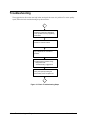
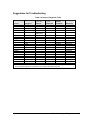
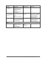
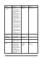
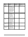
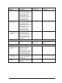
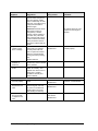
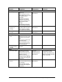
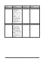
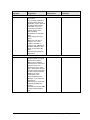
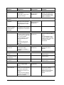
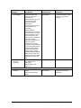
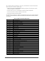
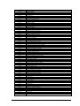
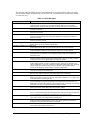
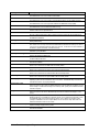
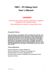
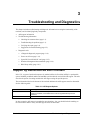
3
Troubleshooting and Diagnostics
This chapter includes troubleshooting and diagnostic information for testing the functionality of the
notebook, and for identifying faulty components:
•
ASP support information
•
Troubleshooting information
•
!
Checking for customer abuse (page 3-3).
!
Troubleshooting the problem (page 3-3).
!
Verifying the repair (page 3-4).
!
Suggestions for troubleshooting (page 3-5).
Diagnostic tools
!
e-Diagtools diagnostic program (page 3-18).
!
Power-on self-test (page 3-19).
!
Sycard PCCtest 450/460 PC card (page 3-25).
!
Windows Management Instrumentation (page 3-26).
!
BIOS Setup utility (page 3-26).
Support by Authorized Service Providers
In the U.S., support of notebook computers by Authorized Service Providers (ASPs) is a purchasable
option. Standard predefined models and standard special models do not include ASP support. The sales
force has the option of creating models with ASP support using the specials process.
The serial number label on the bottom of the notebook indicates the ASP support status for that model.
See the following table.
Table 3-1. ASP Support Options
Serial Number Label
“NoASP”
“ASP”
ASP Support Status
No reimbursement to ASP for parts or labor. However the ASP is authorized to
repair the notebook, and reimbursement can be negotiated directly with the
customer.
Parts and labor will be reimbursed to the ASP.
In other countries, ASP support is standard in most situations—but you should check the marking on
the serial number label to verify the ASP support status for that model.
Service Manual
Troubleshooting and Diagnostics
3-1
Troubleshooting
The suggestions in this section can help isolate and repair the cause of a problem. To ensure quality
repair, follow the basic troubleshooting steps shown below.
Check the customer’s description
of the problem and any supporting
information.
Check for customer abuse.
Try to duplicate the customer’s
problem.
Troubleshoot the problem using:
- Diagnostic tools.
- Troubleshooting suggestions.
Verify the repair by testing the
functionality of the complete unit.
Figure 3-1. Basic Troubleshooting Steps
3-2
Troubleshooting and Diagnostics
Service Manual
Checking for Customer Abuse
Some notebooks might appear to have been damaged by customer abuse. Use these guidelines to help
determine if this is the case:
•
If the shipping box is seriously damaged, customer abuse cannot be declared.
•
If the damage could have a cause other than customer abuse, customer abuse cannot be declared.
•
If the notebook shows any of the following, customer abuse is declared:
!
Missing parts.
!
Broken plastic parts.
!
Parts not original to the notebook.
!
Damaged or missing keys on the keyboard.
Table 3-3 lists additional criteria for determining customer abuse to specific parts of the notebook.
Important
Parts damaged by customer abuse are not covered by the warranty.
Troubleshooting the Problem
Record pertinent information about the notebook:
•
Model and serial number.
•
Operating system and version.
•
Software version (stored in hidden file c:\version.inf).
•
BIOS version.
•
Accessories and peripherals used.
Analyze the problem:
•
Observe Symptoms. Using the customer’s information, try to duplicate the problem. Determine
how the problem differs from proper behavior. Also, note the functions that do work properly.
•
Separate Problems. If there are multiple symptoms, separate them into distinct problems.
•
Consider Causes. Keep in mind possible causes for each problem. Use the diagnostic tools and
troubleshooting suggestions to help find possible causes.
!
!
The e-Diagtools diagnostic program tests most of the notebook’s components using automatic
and interactive tests, and is your primary troubleshooting tool. Other tools include the
power-on self-test, WMI/Toptools (if installed), the BIOS Setup utility, and the Sycard
PCCtest. Table 3-2 on page 3-5 shows how you can use these tools to isolate the cause of the
notebook’s problem.
The troubleshooting suggestions on page 3-6 include general suggestions for repairing
notebooks that show specific failure symptoms.
Service Manual
Troubleshooting and Diagnostics
3-3
Swapping modules that might be defective with others known to be good is generally an ideal way to
find the module responsible for the problem. A failure symptom is rarely caused by more than one
module, so you will not usually need to replace more than one to correct a particular failure.
After you replace a module, the notebook will normally be in a confused state and lock up when you
apply power. If this happens, press the reset button: this turns the notebook off, so that you can restart
it in a known state.
Verifying the Repair
Before returning the repaired notebook to the customer, verify the repair by running the following
tests:
•
e-Diagtools Basic Diagnostic Test. Run the basic test of the e-Diagtools diagnostic program
(page 3-18).
–and–
•
Function Tests. Run tests that check the repaired function, such as those in e-Diagtools
(page 3-18).
–and–
•
3-4
Failed Tests. Run any other tests that failed during troubleshooting.
Troubleshooting and Diagnostics
Service Manual
Suggestions for Troubleshooting
Table 3-2. Scope of Diagnostic Tools
Function
Bootup
Processor
Memory
Fan
Batteries
e-Diagtools
Tests
Tests
Power-On
Self-Test
Tests
Tests
Tests
Tests (CMOS
battery only)
Sycard
PCCtest 450
WMI/
Toptools
(if installed)
Describes
Describes
Describes
Describes
Describes
Tests
Describes
Display
Tests
Tests
Describes
Hard disk
Tests*
Tests
Describes
Floppy drive
Tests
Tests
Describes
Keyboard
Tests
Audio
Tests*
Describes
Serial
Tests
Describes
Parallel
Tests
Describes
LAN
Modem
Wireless
Describes
Infrared
Tests†
PS/2 port
Describes
USB
Port replicator
Tests
Tests
Describes
PCMCIA
Tests
IEEE 1394
Status
AC adapter
* Test might be available only on certain units.
† Use an external keyboard to exercise the port. Run the external 101-key test.
Service Manual
BIOS Setup
Configures
Configures
Configures
Configures
Configures
Configures
Configures
Configures
Configures
Configures
Configures
Configures
Troubleshooting and Diagnostics
3-5
If you cannot isolate the cause of a problem using the above diagnostic tools, use the suggestions in the
following table to help find the problem.
Table 3-3. Troubleshooting Suggestions
Symptom
Call Center:
Suggestions
Repair Center:
Likely Causes
Repair Center:
Comments
To help determine likely causes of a problem, determine which replaceable modules are involved in the system
function and what roles they play: see the figure on page 1-27 and the table on page 1-28.
Startup
Does not boot on
AC or battery.
Beeps once, spins
hard disk, repeats,
but does not boot.
Does not boot on
battery, but boots
on AC.
Does not boot from
floppy drive.
Does not boot from
CD in CD/DVD
drive.
3-6
Check power source.
Press and hold power button
to turn notebook off, then
press power button to turn
notebook on.
Unplug AC adapter, remove
the battery and any PC cards,
press reset button to turn
notebook off, then reconnect
power and try again.
Do not use touch pad while
booting or resuming.
Remove all but one SDRAM
module and try again.
Reinsert any other SDRAM
module and try again.
AC adapter.
SDRAM module.
CPU module.
Switchboard PCA.
Motherboard.
Display assembly.
Hard drive.
Make sure at least one
SDRAM module is installed.
SDRAM module.
Make sure battery is properly
installed and fully charged.
Check battery level on battery
LEDs.
Check battery contacts. If
available, try another battery.
Make sure floppy disk is
bootable.
Use BIOS Setup to check
default boot order.
Make sure CD is bootable.
Use BIOS Setup to check
default boot order.
Restart notebook.
Battery or contacts.
Motherboard.
Troubleshooting and Diagnostics
Check AC adapter. Remove
all but one SDRAM module
and try again.
If power status light does not
turn on, reprogram BIOS,
replace top case, replace
motherboard.
If power status light turns on
but display remains off, try
external monitor. If monitor
shows successful boot,
replace display assembly. If
monitor shows activity but
BIOS does not complete,
replace display assembly. If
monitor is blank, replace
switchboard PCA, replace
motherboard.
If power status light and
display turn on, BIOS
completes, but OS does not
start from hard disk or floppy
drive, replace CPU module,
replace motherboard. If OS
starts from floppy drive,
reload hard drive, replace
hard drive.
Floppy disk or floppy
drive.
Motherboard.
Make sure floppy drive is
installed and connected
correctly.
CD/DVD drive.
Motherboard.
Make sure CD/DVD is
installed and connected
correctly.
Service Manual
Symptom
Sluggish startup or
shutdown.
Error message such
as “Invalid system
disk” or “Auto IDE
error”.
Password forgotten.
Power
No power.
Service Manual
Call Center:
Suggestions
Use Tools tab in disk’s
Properties sheet to check
hard disk. Use Disk
Defragmenter to optimize
hard disk.
Delete temporary and
unneeded files.
Check for disk in floppy drive.
Check boot order in BIOS
Setup.
Remove and reinstall hard
drive.
Repair Center:
Likely Causes
Hard drive.
Repair Center:
Comments
Hard drive contacts.
Hard drive.
If notebook boots from floppy
drive, check for corrupt files
on hard drive, use Recovery
CDs to reinstall factory
software onto hard drive,
replace hard drive.
User must call Technical
Support and provide proof of
ownership. Password
removal is restricted to
certain sites. See page 5-1.
Verify proper ownership, then
follow removal procedure with
owner and record appropriate
data—see page 5-1.
Make sure charged battery is
installed or AC adapter
connected.
Try another battery or AC
adapter if available.
AC adapter.
Battery.
Motherboard.
Troubleshooting and Diagnostics
3-7
Symptom
Notebook has short
operating time when
on battery.
Turns off
immediately after
turning on.
Does not run on
battery; empty
battery indication.
Beeps repeatedly.
Battery does not
charge.
3-8
Call Center:
Suggestions
Turn down display
brightness.
Check timeout settings in
Power in Control Panel.
Check power management
settings in BIOS Setup. Try
default settings.
Battery gauge might need
calibration. Run HP Battery
Optimizer from Start menu.
Certain applications can
cause excess CPU and
power usage. (User can get
Intel Power Monitor from
www.intel.com and monitor
CPU load.)
When playing DVD movies
on battery power, use Power
Options in Control Panel to
select Portable/Laptop power
scheme.
When using applications with
automatic save feature (such
as MS Word), extend save
time or disable to reduce hard
disk access and power
usage.
PCMCIA card use can affect
battery life. Some PCMCIA
cards draw power even while
not in use.
Heavy modem use can affect
battery operating time.
Battery may be extremely
low. Plug in AC adapter or
insert charged battery
Check battery and contacts.
Try another battery if
available.
Notebook beeps repeatedly
when battery is low. Connect
AC adapter or replace
battery.
Make sure AC adapter has
correct power rating.
Make sure AC adapter is
connected properly and
battery installed properly.
Check battery contacts. If
available, try another battery
and AC adapter.
Move notebook away from
any nearby heat source.
Unplug AC adapter and allow
battery to cool. Check for
blocked air vents.
Troubleshooting and Diagnostics
Repair Center:
Likely Causes
Battery.
Motherboard.
Repair Center:
Comments
Battery capacity often
decreases after a year or
more.
Battery.
Battery or contacts.
Motherboard.
Battery.
Battery or contacts.
AC adapter.
Motherboard.
Heatsink.
Check battery and AC
adapter.
Check heatsink.
Service Manual
Symptom
AC adapter does
not power
notebook.
Battery indicator is
inaccurate.
Standby/resume
General problems.
Notebook resumes
slowly from Standby
mode.
Does not suspend
to Standby mode as
expected.
Does not
automatically enter
Hibernation mode
as expected.
Service Manual
Call Center:
Suggestions
Try another AC adapter, if
available.
Repair Center:
Likely Causes
AC adapter.
Motherboard.
Repair Center:
Comments
AC adapter cannot be
repaired, and must be
replaced.
Time Remaining is an
estimate based on
notebook’s power use at that
moment. It therefore depends
on current task, and assumes
power will be used at that
rate until battery runs out. So
if notebook is currently using
good deal of power (such as
when reading CD or DVD),
Time Remaining likely shows
less time than actually
remains.
Close all applications before
entering (or allowing
notebook to enter) Standby or
Hibernation mode.
If problem appears after
installing new software
(including drivers), uninstall
that software. Contact
software vendor for additional
support.
Notebook can take a minute
or longer to resume if network
card is installed. Blinking
cursor appears while system
is loading and checking
hardware and network
connections. When hardware
is reinitialized, Windows
desktop appears.
Notebook won’t suspend if
connection to another
computer is active.
If notebook is busy, it
normally finishes current
operation before suspending.
Make sure hibernate support
is enabled in Power in
Control Panel. Also, make
sure Hibernate timeouts
(Power Schemes tab) for AC
and battery power are not set
to Never.
Troubleshooting and Diagnostics
3-9
Symptom
Display
Dark display, no
light.
White display.
Call Center:
Suggestions
Repair Center:
Likely Causes
Repair Center:
Comments
Make sure notebook is turned
on and warmed up.
Check power supply.
Make sure SDRAM modules
are installed properly.
Adjust display brightness.
Press Fn+F5 several times.
Try external monitor.
Display cable
connection.
SDRAM modules.
CPU module.
Display assembly.
Motherboard.
Check cable connections.
Replace SDRAM modules.
Make sure CPU module is
installed properly, replace
CPU module.
Check display cable
connections, replace display
assembly.
If external monitor displays
no image, replace
motherboard.
Adjust display brightness.
Display assembly.
Switchboard PCA.
Display cable
connection.
Switchboard PCA.
Display assembly.
Motherboard.
Display cable
connection.
Display assembly.
Erratic display.
Bright or missing
pixels or lines.
See quality statement on
page 5-2.
Punctured display.
Vertical crack near
center of display.
Scratched display
glass.
Local area of dark
or light discoloration
visible when display
is on.
External display
does not work.
Hard disk
Hard disk never
spins.
Hard disk makes
clunking or
scratching noise.
Hard disk makes
buzzing or whining
noise.
3-10
Usually caused by
closing display with
pencil-sized object on
keyboard.
Caused by excessive
pressure applied to
area on screen.
Check connections.
Press Fn+F5 several times.
Try display on another
computer.
External display.
Motherboard.
Check power source.
Remove and reinstall hard
drive. Check connector.
Back up disk immediately.
Was notebook or drive
dropped?
Back up disk immediately.
Check hard disk installation.
Check for alternate noise
sources, such as PCMCIA
drive or fan.
Hard drive or
connector.
Motherboard.
Hard drive.
Troubleshooting and Diagnostics
Check display cable
connection.
Check display cable
connection.
See quality statement on
page 5-2.
Declared to be caused by
customer abuse.
Declared to be caused by
customer abuse.
Declared to be caused by
customer abuse.
Declared to be caused by
customer abuse.
If drive case is damaged,
drive may not operate
properly.
Check notebook and drive for
evidence of customer abuse.
Depends on noise
source.
Service Manual
Symptom
Files corrupted.
Disk capacity less
than normal.
Disk’s reported
capacity is less than
actual size
Floppy drive
General problems.
CD/DVD drive
Particular CD or
DVD not playing
properly.
Cannot read any
CD or DVD.
DVD movie stops
playing.
Service Manual
Call Center:
Suggestions
Run virus scan program.
Check hard disk using Tools
tab in disk’s Properties sheet.
Test hard disk drive with
e-Diagtools diagnostics.
Back up files if possible, then
use Recovery CDs to
reformat hard disk and
reinstall factory software.
Check hard disk using Tools
tab in disk’s Properties sheet.
Check partitions using
Control Panel, Administrative
Tools, Computer
Management under Storage.
Use Recovery CDs to
reformat hard disk and
reinstall factory software.
Hard disk allocates
approximately 20 MB to
diagnostic software. This
space is unavailable for other
uses, and not included in
hard disk capacity reported
by Windows.
No response from floppy
drive.
Check disk for proper
insertion, dirt, or damage.
Clean with soft cloth or
replace as needed.
If CD was created on CD-RW
drive, try using HP certified
media. Read and write quality
can vary for other media.
Restart notebook.
Make sure CD/DVD drive is
installed properly.
DVD may be double-sided.
Movie may be paused. Press
Play button.
Repair Center:
Likely Causes
Repair Center:
Comments
Hard drive.
Floppy drive.
Motherboard.
Make sure floppy drive is
installed and connected
correctly.
CD/DVD drive.
Troubleshooting and Diagnostics
3-11
Symptom
Region Code error.
“System Error:
Unable to read
drive” message.
No DVD or CD-RW
software on
notebook.
All DVD play is
erratic.
Keyboard
Some or all keys do
not work properly.
Embedded numeric
keypad does not
work.
PS/2 keyboard
and mouse with
Y-adapter do not
work.
3-12
Call Center:
Suggestions
DVDs contain embedded
regional codes that prevent
them from playing outside
region in which they are sold.
This error occurs when trying
to play DVD intended for
different region.
Important: Most DVD drives
allow region code to be
changed only a limited
number of times (usually no
more than four). When this
limit is reached, last change
is hard-coded on DVD drive,
and is permanent. Refer to
DVD player software help for
details.
Make sure disk is clean,
undamaged, and inserted
correctly. Clean with soft
cloth or replace as needed.
Wait 5 to 10 seconds after
closing tray before pressing
Play.
Restart notebook.
If software was removed, use
the Recovery CDs to reinstall
factory software.
Some DVDs include software
called “PC Friendly”. This
software can cause errors or
erratic play. If needed,
uninstall PC Friendly and
restart notebook.
Check settings in Control
Panel.
Press Fn+F8 to activate
numeric keypad, and Lock
key to turn on number lock.
Avoid touching touch pad
while booting or resuming.
Check devices separately.
Troubleshooting and Diagnostics
Repair Center:
Likely Causes
Repair Center:
Comments
HP warranty does not cover
expense of correcting this
situation.
CD/DVD drive.
Motherboard.
Make sure CD/DVD drive is
installed properly.
Keyboard.
Motherboard.
Keyboard.
Motherboard.
Try reinserting ribbon cable in
connector on motherboard.
Y-adapter.
PS/2 device.
Motherboard.
Service Manual
Symptom
Touch pad
General problems.
Special touch pad
features not
working.
Call Center:
Suggestions
Repair Center:
Likely Causes
Reset notebook (see
page 1-21).
Check settings in Control
Panel. Make sure touch pad
is enabled in Mouse
Properties.
By default, touch pad is
disabled if external PS/2
mouse is connected, Use
BIOS Setup to check
settings.
Avoid touching touch pad
while booting or resuming.
In Mouse Properties, select
Synaptics PS/2 TouchPad
driver. (Driver is installed
from \hp\drivers\touchpad.)
Top case.
Motherboard.
Click button does
not work.
Memory
Out of memory
error.
Notebook does not
boot after adding
SDRAM.
Audio
No sound audible.
Sound does not
record.
Service Manual
Repair Center:
Comments
Top case.
Motherboard.
Top case.
Motherboard.
Make sure C drive has
adequate free space. Delete
temporary and unneeded
files.
Use memory troubleshooter
in Windows Help.
Not all third-party memory
cards have been tested for
use with notebook.
Use only DDR-266 SDRAM
modules.
SDRAM module.
Increase sound volume.
Check whether sound is
enabled (mute button and
software controls).
Check for sound resource
conflicts in Device Manager.
Test audio with e-Diagtools
diagnostics.
Use an external microphone
(internal microphone normally
not included).
Check software controls.
Test audio with e-Diagtools
diagnostics.
Top case.
Speaker assembly.
Switchboard PCA.
Motherboard.
SDRAM module.
Check operation using
headphones or external
speakers (switchboard PCA).
Make sure speaker assembly
cable is connected.
Switchboard PCA.
Motherboard.
Troubleshooting and Diagnostics
3-13
Symptom
Serial/Parallel/USB
General problems.
Modem
General problems.
3-14
Call Center:
Suggestions
Repair Center:
Likely Causes
Check connections.
Restart notebook.
Use troubleshooters in
Windows Help.
Check settings in Control
Panel.
Check port settings in Device
Manager.
Test ports with e-Diagtools
diagnostics.
For USB: contact device
vendor and HP Notebook
Web site (see page vi) for
latest USB drivers.
For USB: if the device is
powered by the USB port, try
the other port.
Motherboard.
Check settings in Control
Panel.
Open hardware Device
Manager. If modem is
disabled, try to enable. If
modem has a conflict, try
disabling another device.
Use analog telephone line
(2, 3, or 4 wires), not PBX or
digital line. In a hotel, ask for
data line.
Try disabling error correction
and data compression.
Test modem with e-Diagtools
diagnostics.
Motherboard.
Troubleshooting and Diagnostics
Repair Center:
Comments
Service Manual
Symptom
LAN/network
General problems.
Infrared
General problems.
Service Manual
Call Center:
Suggestions
Repair Center:
Likely Causes
Check cables and
connections.
Try connecting notebook to
another network station (if
applicable). If green light next
to LAN port does not light,
LAN cable may not be
connected to network or
network may be down.
Use networking
troubleshooter in Windows
Help.
Check settings in Control
Panel.
Make sure LAN cable is
Category 3, 4, or 5 for
10Base-T operation, or
Category 5 for 100Base-TX
operation. Maximum cable
length is 100 meters (330
feet).
Test LAN with e-Diagtools
diagnostics.
Motherboard.
Infrared is disabled and no
drivers installed as shipped.
(Drivers are included.)
Make sure line between
infrared ports is not blocked,
ports face each other
squarely and are no more
than 1 meter apart. Sunlight,
heat from nearby equipment,
or other sources of infrared
radiation can cause
transmission errors.
Open Hardware Device
Manager. Try to enable the
infrared port.
Remove any PC cards from
notebook (possible IRQ
conflict).
For fast-IrDA, check for DMA
conflict with ECP parallel
port.
Motherboard.
Repair Center:
Comments
Troubleshooting and Diagnostics
3-15
Symptom
Wireless
General problems.
One-Touch button
problems
Buttons not working
properly.
On-screen display
does not appear
when button is
pressed.
PCMCIA
General problems.
AC adapter
Does not power
notebook.
Motherboard
Evidence of spilled
liquid.
Bent or broken
connectors, or burnt
component.
Motherboard
cracked.
Miscellaneous
Clock loses time
Notebook gets
abnormally hot.
3-16
Call Center:
Suggestions
Repair Center:
Likely Causes
Repair Center:
Comments
Check TCP/IP setup in
Control Panel.
Check SSID, channel, and
encryption settings.
Mini-PCI card.
Antenna PCAs.
Motherboard.
Make sure all cables are
properly connected to miniPCI card and motherboard.
Check for damaged coaxial
cables or connectors.
Make sure correct
applications are associated
with buttons in One-Touch
tab of Keyboard in Control
Panel.
Make sure Onscreen Display
is enabled in One-Touch tab
of Keyboard in Control Panel.
Keyboard cover.
Switchboard PCA.
Motherboard.
Restart notebook.
Try card in another computer.
If card requires an IRQ, make
sure one is available.
In Device Manager, refresh
device list and check for
conflicts.
Download current drivers
from card manufacturer’s
Web site.
PCMCIA socket.
Motherboard.
Using a flashlight, look for
bent pins inside the PCMCIA
socket.
For model XE4500, if only
one slot is affected, replace
PCMCIA socket. If both slots
are affected, replace
motherboard.
Make sure AC adapter has
correct power rating.
Try another AC adapter, if
available.
AC adapter.
Motherboard.
AC adapter cannot be
repaired and must be
replaced.
Declared to be caused by
customer abuse.
Declared to be caused by
customer abuse.
Declared to be caused by
customer abuse.
Plug in AC adapter for 24
hours to charge CMOS
battery.
Always set notebook on a flat
surface, so air can flow freely
around and underneath it
Make sure air vents are not
blocked.
Games and other programs
that drive CPU usage toward
100% can contribute.
Troubleshooting and Diagnostics
CMOS battery.
Motherboard.
Charge CMOS battery.
Heatsink.
Check heatsink for damage
or proper fan operation.
Check thermal contact
between CPU and heatsink.
Replace thermal pad if
needed.
Service Manual
Symptom
Notebook pauses or
runs sluggishly.
Notebook still on
but stops
responding.
Accessories
Port replicator
problems.
Service Manual
Call Center:
Suggestions
May be normal Windows
behavior (background
processing can affect
response time).
Certain operations (such as
virus scanning or file
browsers) can affect
performance.
Press Ctrl+Alt+Del to see if
an application is not
responding.
Restart notebook.
If hard disk has spun down to
conserve power, it can take
several seconds to spin up
(you can hear this). Use
Control Panel to modify hard
disk power settings.
Check for overheating—see
previous symptom.
If notebook’s hard drive
frequently runs (as indicated
by hard drive light on front of
notebook) while notebook
appears to be paused or
running slowly, consider
installing additional SDRAM.
Make sure hard drive has
adequate free space. Delete
temporary and unneeded
files.
Press Ctrl+Alt+Del and end
any application not
responding.
Reset notebook (see
page 1-21).
Repair Center:
Likely Causes
CPU module.
Motherboard.
Repair Center:
Comments
If notebook slows after period
of continuous activity, check
heatsink—see previous
symptom.
Check notebook’s power
supply.
Check settings in BIOS
Setup.
Port replicator.
Motherboard.
Port replicator is not
repairable, and must be
exchanged.
Troubleshooting and Diagnostics
3-17
Diagnostic Tools
This section describes the following diagnostic tools you can use for troubleshooting and repairing the
notebook:
•
Notebook e-Diagtools diagnostic program (below).
•
Power-on self-test (page 3-19).
•
Sycard PCCtest 450 PC card (page 3-25).
•
Windows Management Instrumentation (page 3-26).
•
BIOS Setup utility (page 3-26).
e-Diagtools Diagnostic Program
The hardware diagnostic programs provide two levels of testing:
•
User-level testing using a basic hardware test.
•
Advanced testing using individual hardware tests.
The tests are designed to run after the system reboots, so that the notebook will be in a predictable state
during the tests. The tests are non-destructive, and are intended to preserve the state of the notebook.
The notebook reboots when you exit the program so drivers can be loaded.
Updating e-Diagtools
You can download the latest version of e-Diagtools using e-Diagtools for Windows.
Running e-Diagtools
The following procedure describes how to run e-Diagtools. The individual steps might differ slightly
for different versions of e-Diagtools.
1. Click Start > Turn Off Computer (or Shut Down), Restart.
2. When the HP logo appears, press F10 to start the diagnostic test.
The first time you run the program, you are prompted to select the language for the program.
3. When the menu appears, press F2 to run e-Diagtools.
4. When the Configuration Description appears, check the list of detected hardware.
5. Run the basic test. Press F2 to start the basic hardware test. The results appear when the test is
complete.
6. If you intend to exit without running the advanced tests, press F4 to view the Support Ticket. Press
F3 to exit e-Diagtools.
7. Optional: run the advanced tests. Press F2 to open the advanced test screen.
8. Use the arrow keys and ENTER to select the test you want to run. Tests are listed only for detected
hardware.
9. Press F2 to run the selected tests and add the results to the Support Ticket.
3-18
Troubleshooting and Diagnostics
Service Manual
10. After each run, press F2 to return to the advanced test screen, or press F4 to view the Support
Ticket.
11. Exit. Press F3 and then any key to exit and reboot.
12. Optional: open the Support Ticket. In Windows, click Start > All Programs (or Programs) >
Hewlett-Packard > Notebook > HP e-Diagtools > e-Diagtools for Windows.
13. Click View to display the Support Ticket.
14. To add information about your problem, click Comments, type the information, and then click OK.
To save or print the Support Ticket, click Save As or Print.
To e-mail the Support Ticket to your support agent, click e-Mail. The first time you make an email connection from this program, click Change Settings in the Connect window and enter the
settings recommended by your support agent.
e-Diagtools for Windows can also update the version of e-Diagtools on your notebook’s hard disk. In
e-Diagtools for Windows, use the e-Diagtools menu.
If you have trouble running e-Diagtools diagnostics from the hard disk, you can also run it from the
Recovery CD or DVD. Boot from the CD or DVD and select the diagnostics option.
Interpreting the Results
The e-Diagtools diagnostic program returns test groups, error codes, and suggestions for repair and/or
follow-up actions. The basic hardware test shows a recommended replacement part.
To help interpret the results of the e-Diagtools tests, refer to the following:
•
e-Diagtools Support Ticket on page 3-19.
•
Replaceable Module Diagram on page 1-27
•
Functional Structure Description on page 1-28
This combined information should enable you to determine which of the notebook’s components
require service.
Power-On Self-Test
Note
If Quiet Boot is enabled in BIOS Setup (the default setting), press Esc during boot to see POST
messages.
When the notebook boots, its system BIOS runs a series of initialization routines and diagnostic tests
called POST (Power-On Self-Test). The BIOS will not boot the notebook’s operating system if the
system memory, CPU, DMA, or interrupt controller fails the POST diagnostic tests. POST indicates
progress by a sequence of codes; if an error occurs, the BIOS displays a message and/or issues a beep
code.
Note that not all POST messages indicate a failure in the notebook—some messages are for
information only. You should not necessarily interpret the failure of one or more POST tests as a
hardware, software, or firmware failure. If POST displays an error message or issues a beep code
indicating an error, confirm the problem using other diagnostic tools.
Service Manual
Troubleshooting and Diagnostics
3-19
First, confirm the failure by performing a “clean” boot, as described below. Note that if the notebook
fails to restart with a clean boot, it requires repair.
1. Remove all accessories, including SDRAM modules, port replicator, PC cards, printer, external
monitor, pointing device, and keyboard.
2. Provide “clean” AC power—no auto adapter or unusual AC adapter configuration.
3. Press the reset button to return the notebook to a known state.
4. Press the power button to start the notebook.
If the BIOS detects a terminal error condition, it halts POST after issuing a beep code and/or displaying
a message (see the following table). The beep code indicates the POST routine in which the terminal
error occurred.
Table 3-4. POST Terminal-Error Beep Codes
Beep Codes*
1
1-2
1-1-1-3
1-1-1-4
1-1-2-1
1-1-2-3
1-1-2-4
1-1-3-1
1-1-3-2
1-1-3-3
1-1-3-4
1-1-4-1
1-1-4-3
1-1-4-4
1-2-1-1
1-2-1-2
1-2-1-3
1-2-1-4
1-2-2-1
1-2-2-3
1-2-2-4
1-2-3-1
1-2-3-3
1-2-4-1
1-3-1-1
1-3-1-3
1-3-2-1
1-3-3-1
1-3-3-2
1-3-3-3
1-3-4-1
1-3-4-3
1-3-4-4
1-4-1-1
1-4-1-3
1-4-1-4
1-4-2-3
1-4-3-1
1-4-3-3
1-4-4-1
1-4-4-2
2-1-1-2
2-1-1-3
2-1-2-2
2-1-2-3
2-1-2-4
2-1-3-1
2-1-3-2
2-1-3-3
2-1-3-4
2-1-4-1
3-20
POST Description
One short beep before boot.
Search for option ROMs.
Verify Real Mode.
Disable Non-Maskable Interrupt (NMI).
Get CPU type.
Initialize system hardware.
Disable shadow and execute code from ROM.
Initialize chipset with initial POST values.
Set IN POST flag.
Initialize CPU registers.
Enable CPU cache.
Initialize caches to initial POST values.
Initialize I/O component.
Initialize local bus IDE.
Initialize Power Management.
Load alternate registers with initial POST values.
Restore CPU control word during warm boot.
Initialize PCI Bus Mastering devices.
Initialize keyboard controller.
BIOS ROM checksum.
Initialize cache before memory Auto size.
8254 timer initialization.
8237 DMA controller initialization.
Reset Programmable Interrupt Controller.
Test DRAM refresh.
Test 8742 Keyboard Controller (on motherboard).
Set ES segment register to 4 GB.
Auto size DRAM; or wrong type or no RAM installed.
Initialize POST Memory Manager.
Clear 512 kB base RAM.
RAM failure on address line xxxx.
RAM failure on data bits xxxx of low byte of memory bus.
Enable cache before system BIOS shadow.
RAM failure on data bits xxxx of high byte of memory bus.
Test CPU bus-clock frequency.
Initialize Phoenix Dispatch Manager.
Warm start shut down.
Shadow system BIOS ROM.
Auto size cache.
Advanced configuration of chipset registers.
Load alternate registers with CMOS values.
Initialize extended memory for RomPilot.
Initialize interrupt vectors.
POST device initialization.
Check ROM copyright notice.
Initialize I20 support.
Check video configuration against CMOS.
Initialize PCI bus and devices.
Initialize all video adapters in system.
QuietBoot start (optional).
Shadow video BIOS ROM.
Troubleshooting and Diagnostics
Service Manual
Beep Codes*
2-1-4-3
2-1-4-4
2-2-1-1
2-2-1-2
2-2-1-3
2-2-2-1
2-2-2-2
2-2-3-1
2-2-3-2
2-2-3-3
2-2-3-4
2-2-4-1
2-3-1-1
2-3-1-3
2-3-2-1
2-3-2-3
2-3-2-4
2-3-3-1
2-3-3-2
2-3-3-3
2-3-3-4
2-3-4-1
2-3-4-3
2-4-1-1
2-4-1-3
2-4-2-3
2-4-4-1
2-4-4-2
2-4-4-3
3-1-1-1
3-1-1-2
3-1-1-3
3-1-1-4
3-1-2-1
3-1-2-2
3-1-2-3
3-1-2-4
3-1-3-1
3-1-3-2
3-1-3-3
3-1-3-4
3-1-4-1
3-1-4-4
3-2-1-1
3-2-1-2
3-2-1-3
3-2-1-4
3-2-2-2
3-2-2-3
3-2-2-4
3-2-3-2
3-2-3-3
3-2-4-1
3-2-4-2
3-2-4-3
3-2-4-4
3-3-1-1
3-3-1-3
3-3-2-1
3-3-3-1
3-3-3-3
3-3-4-1
3-3-4-3
3-4-1-1
3-4-1-2
3-4-1-3
3-4-2-2
3-4-2-3
3-4-2-4
3-4-3-2
3-4-3-3
3-4-3-4
Service Manual
POST Description
Display BIOS copyright notice.
Initialize MultiBoot.
Display CPU type and speed.
Initialize EISA board.
Test keyboard.
Set key click if enabled.
Enable USB devices.
Test for unexpected interrupts.
Initialize POST display service.
Display prompt "Press F2 to enter SETUP".
Disable CPU cache.
Test RAM between 512 and 640 kB.
Test extended memory.
Test extended memory address lines.
Jump to UserPatch1.
Configure advanced cache registers.
Initialize Multi Processor APIC.
Enable external and CPU caches.
Set up System Management Mode (SMM) area.
Display external L2 cache size.
Load custom defaults (optional).
Display shadow-area message.
Display possible high address for UMB recovery.
Display error messages.
Check for configuration errors.
Check for keyboard errors.
Set up hardware interrupt vectors.
Initialize Intelligent System Monitoring.
Initialize coprocessor if present.
Disable onboard Super I/O ports and IRQs.
Late POST device initialization.
Detect and install external RS232 ports.
Configure non-MCD IDE controllers.
Detect and install external parallel ports.
Initialize PC-compatible PnP ISA devices.
Re-initialize onboard I/O ports.
Configure Motherboard Configurable Devices (optional).
Initialize BIOS Data Area.
Enable Non-Maskable Interrupts (NMIs).
Initialize Extended BIOS Data Area.
Test and initialize PS/2 mouse.
Initialize floppy controller.
Determine number of ATA drives (optional).
Initialize hard-disk controllers.
Initialize local-bus hard-disk controllers.
Jump to UserPatch2.
Build MPTABLE for multi-processor boards.
Install CD-ROM for boot.
Clear huge ES segment register.
Fix up Multi Processor table.
Check for SMART Drive (optional).
Shadow option ROMs.
Set up Power Management.
Initialize security engine (optional).
Enable hardware interrupts.
Determine number of ATA and SCSI drives.
Set time of day.
Check key lock.
Initialize typematic rate.
Erase F2 prompt.
Scan for F2 keystroke.
Enter SETUP.
Clear Boot flag.
Check for errors.
Inform RomPilot about the end of POST.
POST done - prepare to boot OS.
Terminate QuietBoot (optional).
Check password (optional).
Initialize ACPI BIOS.
Prepare Boot.
Initialize SMBIOS.
Initialize PnP Option ROMs.
Troubleshooting and Diagnostics
3-21
Beep Codes*
3-4-4-1
3-4-4-2
3-4-4-3
3-4-4-4
4-1-1-1
4-1-1-2
4-1-1-3
4-1-1-4
4-1-2-1
4-1-2-2
4-1-2-3
4-1-2-4
4-1-3-1
4-1-3-2
4-1-3-3
4-1-3-4
4-1-4-1
4-1-4-2
4-1-4-3
4-2-1-3
4-3-1-1
4-3-1-2
4-3-1-3
4-3-1-4
4-3-2-1
4-3-2-2
4-3-2-3
4-3-2-4
4-3-3-1
4-3-3-2
4-3-3-3
4-3-3-4
4-3-4-1
4-3-4-2
4-3-4-3
4-3-4-4
4-4-1-1
4-4-1-2
4-4-1-3
4-4-1-4
4-4-2-1
4-4-2-2
4-4-2-3
4-4-2-4
1 long,
2 short
3-22
POST Description
Clear parity checkers.
Display MultiBoot menu.
Clear screen (optional).
Check virus and backup reminders.
Try to boot with INT 19.
Initialize POST Error Manager (PEM).
Initialize error logging.
Initialize error display function.
Initialize system error handler.
PnPnd dual CMOS (optional).
Initialize note dock (optional).
Initialize note dock late.
Force check (optional).
Extended checksum (optional).
Redirect Int 15h to enable remote keyboard.
Redirect Int 13h to Memory Technologies Devices such as ROM, RAM, PCMCIA, and serial disk.
Redirect Int 10h to enable remote serial video.
Re-map I/O and memory for PCMCIA.
Initialize digitizer and display message.
Unknown interrupt.
Initialize the chipset.
Initialize the bridge.
Initialize the CPU.
Initialize system timer.
Initialize system I/O.
Check force recovery boot.
Checksum BIOS ROM.
Go to BIOS.
Set Huge Segment.
Initialize Multi Processor.
Initialize OEM special code.
Initialize PIC and DMA.
Initialize Memory type.
Initialize Memory size.
Shadow Boot Block.
System memory test.
Initialize interrupt vectors.
Initialize Run Time Clock.
Initialize video.
Initialize System Management Manager.
Output one beep.
Clear Huge Segment.
Boot to Mini DOS.
Boot to Full DOS.
Improper video configuration (reprogram EEPROM) or external ROM checksum failure.
Troubleshooting and Diagnostics
Service Manual
The following table lists POST messages and explanations for reported problems. If the system fails
after you make changes in BIOS Setup, reset the notebook, enter BIOS Setup, and install the defaults
or correct the error.
Table 3-5. POST Messages
Message
Description
0200 Failure Fixed Disk
Fixed (hard) disk is not working or not configured properly. Make sure the hard disk is
installed properly. Run BIOS Setup and make sure the hard disk type is correctly identified.
0210 Stuck key
Stuck key on keyboard.
0211 Keyboard error
Keyboard is not working.
0212 Keyboard Controller Failed
Keyboard controller failed the test. might require replacing the motherboard (contains the
keyboard controller).
0213 Keyboard locked – Unlock key switch
Unlock the system to proceed.
0220 Monitor type does not match CMOS – Run SETUP
Monitor type is not correctly identified in BIOS Setup.
0230 Shadow RAM Failed at offset: nnnn
Shadow RAM failed at offset nnnn of the 64k block at which the error was detected.
0231 System RAM Failed at offset: nnnn
System RAM failed at offset nnnn of the 64k block at which the error was detected.
0232 Extended RAM Failed at offset: nnnn
Extended memory is not working or not configured properly at offset nnnn. Update to the
latest BIOS version.
0250 System battery is dead – Replace and run SETUP
CMOS clock battery indicator shows that the CMOS battery is dead. Connect the AC adapter
for at least 24 hours, then run BIOS Setup to reconfigure the system.
0251 System CMOS checksum bad – Default configuration used
System CMOS has been corrupted or modified incorrectly, perhaps by an application that
changes CMOS data. In response, the BIOS has installed the default Setup values. Use BIOS
Setup to modify these values if needed. If the error persists, check the system battery.
Connect the AC adapter for at least 24 hours; replace the motherboard.
0260 System timer error
Timer test failed. Replace the motherboard.
0270 Real time clock error
Real-time clock failed the BIOS test. Might require replacing the motherboard.
0271 Check date and time settings
BIOS found the date or time to be out of range, and reset the real-time clock. You might need
to use BIOS Setup to reset the legal date.
0280 Previous boot incomplete – Default configuration used
Previous POST did not complete successfully. POST loads default values and offers to run
BIOS Setup. If the failure was caused by incorrect values that are not corrected, the next boot
will likely fail. This error is cleared the next time the system is booted.
0281 Memory Size found by POST differed from CMOS
Memory size found by POST differed from that specified in CMOS.
02B0 Diskette drive A error
Drive A: is present but fails the BIOS POST diskette tests. Make sure the drive is defined with
the proper diskette type in BIOS Setup and that the drive is connected correctly.
02B2 Incorrect Drive A type – run SETUP
Type of floppy drive A: not correctly identified in BIOS Setup.
02D0 System cache error – Cache disabled
RAM cache failed and BIOS disabled the cache. May require replacing the motherboard.
A disabled cache slows system performance considerably.
02F0: CPU ID:
CPU socket number for Multi-Processor error.
Service Manual
Troubleshooting and Diagnostics
3-23
Message
Description
02F4: EISA CMOS not writeable
ServerBIOS2 test error: Cannot write to EISA CMOS.
02F5: DMA Test Failed
ServerBIOS2 test error: Cannot write to extended Direct Memory Access (DMA) registers.
02F6: Software NMI Failed
ServerBIOS2 test error: Cannot generate software Non-Maskable Interrupt (NMI).
02F7: Fail-Safe Timer NMI Failed
ServerBIOS2 test error: Fail-safe timer takes too long.
device Address Conflict
Address conflict for the specified device.
Allocation Error for: device
Run ISA or EISA Configuration Utility to resolve a resource conflict for the specified device.
CD ROM Drive
CD-ROM drive identified.
Entering SETUP ...
Starting BIOS Setup.
Failing Bits: nnnn
Hex number nnnn is a map of the bits at the RAM address that failed the memory test. Each 1
(one) in the map indicates a failed bit. See errors 230, 231, or 232 above for offset address of
the failure in System, Extended, or Shadow memory.
Fixed Disk n
Fixed disk n (0–3) identified.
Invalid System Configuration Data
Problem with NVRAM (CMOS) data.
I/O device IRQ conflict
I/O device IRQ conflict error.
PS/2 Mouse Boot Summary Screen:
PS/2 mouse installed.
nnnn kB Extended RAM Passed
Where nnnn is the amount of RAM in kB successfully tested.
nnnn Cache SRAM Passed
Where nnnn is the amount of system cache in kB successfully tested.
nnnn kB Shadow RAM Passed
Where nnnn is the amount of shadow RAM in kB successfully tested.
nnnn kB System RAM Passed
Where nnnn is the amount of system RAM in kB successfully tested.
Operating system not found
Operating system cannot be located on drive A: or drive C:. Enter BIOS Setup and see if the
hard disk and drive A: are properly identified.
Parity Check 1 nnnn
Parity error found in the system bus. BIOS attempts to locate the address and display it on the
screen. Parity is a method for checking errors in binary data. A parity error indicates that data
has been corrupted.
Parity Check 2 nnnn
Parity error found in the I/O bus. BIOS attempts to locate the address and display it on the
screen.
Press <F1> to resume, <F2> to Setup, <F3> for previous
Displayed after any recoverable error message. Press <F1> to start the boot process or <F2>
to enter BIOS Setup and change the settings. Press <F3> to display the previous screen
(usually an initialization error of an Option ROM, such as an add-on card). Write down and
follow the information shown on the screen.
Press <F2> to enter Setup
Optional message displayed during POST.
PS/2 Mouse:
PS/2 mouse identified.
3-24
Troubleshooting and Diagnostics
Service Manual
System BIOS shadowed
System BIOS copied to shadow RAM.
UMB upper limit segment address: nnnn
Displays the address nnnn of the upper limit of Upper Memory Blocks (UMB), indicating
released segments of the BIOS that can be reclaimed by a virtual memory manager.
Video BIOS shadowed
Video BIOS copied to shadow RAM.
Sycard PCCtest 450/460 PC Card (Optional)
The PCCtest 450 and 460 cards (version 1.05) from Sycard Technology are the only recommended
diagnostic tools that test the functionality of the PCMCIA slots using a PCMCIA card. Each is a
Type II PC card that works with test software to exercise PCMCIA functions. (For details, see the
Sycard Technology Web site: http://www.sycard.com).
The PCCtest product contains these components:
•
PCCtest 450 or 460 (revision 1.05) PC card.
•
PCCtest 450/460 software disk. (Software updates are available at the Sycard Technology
Web site.)
•
Configuration headers (PC card/16-bit and CardBus/32-bit) that attach to the card.
You will also need a CardBus extender card (such as the Sycard PCCextend 70) to avoid wear on the
Sycard PCMCIA connector.
Use the following tests to check the function of the notebook’s PCMCIA slots. See the Sycard
documentation for details about running the tests.
Table 3-6. Sycard PCCtest Commands
All notebook models
(PCI 1520)
Service Manual
Slot
Upper
Lower
PCMCIA PC card (16-bit) test
(PC card configuration header)
pct450-v-1-b80
pct450-v-0-b80
CardBus (32-bit) test
(CardBus configuration header)
testcb-v-1-b80
testcb-v-0-b80
Troubleshooting and Diagnostics
3-25
Windows Management Instrumentation (WMI)
The Windows Management Instrumentation is basically sets of rules for accessing information about a
notebook. WMI allows an application to determine, for example, the operating system being used,
which hardware and software components are in the notebook, and possibly whether any of the
components need replacing. A local or remote application can use the WMI interface to check which
hardware and software components are installed on your notebook, and might be able to tell how well
they are working or if they need replacement.
Installing the WMI Package
The WMI package is either preinstalled on the notebook’s hard disk or can be downloaded from
http://www.hp.com/toptools (the contents are the same in both cases). The package must be properly
installed before it can be used.
To install the WMI preloaded on the hard disk:
1. Start Windows, if it is not already running.
2. Click Start > Programs (or All Programs) > Hewlett-Packard > HP Toptools Agent > Setup.
Using WMI
For a complete description of how to use WMI, see the following documentation provided with the
notebook:
•
A README.TXT file: click Start > Programs > Hewlett-Packard > HP Toptools Agent >
Read me.
•
A Windows online help file describing Hewlett-Packard’s implementation of WMI (group and
attribute definitions): click Start > Programs Hewlett-Packard > HP Toptools Agent > HP Toptools
Help.
Uninstalling the WMI Package
1. Click Start > Programs (or All Programs) > Hewlett-Packard > HP Toptools Agent > Uninstall
WMI.
2. Restart the notebook.
BIOS Setup Utility
The BIOS Setup utility provides access to the notebook’s basic configuration settings. It is independent
of the operating system.
Running the BIOS Setup Utility
1. Close all applications, then restart the notebook: click Start > Turn Off Computer > Restart.
(If necessary, you can press Ctrl+Alt+Del to restart.)
2. When the HP logo appears, press F2 to enter the BIOS Setup utility.
3-26
Troubleshooting and Diagnostics
Service Manual
3. The pointing devices are not active in BIOS Setup, so you will need to use the keyboard to
navigate:
•
Press the LEFT and RIGHT arrow keys to move among menus.
•
Press the UP and DOWN arrow keys to move among parameters in a menu.
•
Press F5 or F6 to move through values for the current parameter, or press Enter to change a
setting.
4. After you select the options you want, press F10 or use the Exit menu to exit BIOS Setup.
If the settings cause a conflict between devices during reboot, the system prompts you to run BIOS
Setup, and marks the conflicting settings.
Note
The listings in the following table are for the initial BIOS release and might differ somewhat for
other models.
Table 3-7. BIOS Setup Menus and Parameters
All notebook models: Introduced with BIOS version KE.01.04 (Fall 2002).
Main Menu
Description
Default
BIOS Revision
Shows the current BIOS version.
System Time
Sets the time using 24-hour format. Values set take effect
immediately.
System Date
Sets the date using dd/mm/yy format (except English, which
uses mm/dd/yy format).
Language
Sets the language for BIOS Setup.
Detected
automatically.
Internal Hard Disk
Sets the hard disk drive type and various parameters.
Detected
automatically.
Extended Memory
Shows the extended memory size.
Detected
automatically.
CPU Serial Number
For a Pentium processor with a serial number, makes the
serial number available to software.
Disabled.
Serial Number
Displays the serial number as shown on the back of the
notebook.
Detected
automatically.
PC ID
Displays the PC ID String stored in the reserved part of
RAM.
Main Menu
Detected
automatically.
Description
Default
Service ID
Displays an identifier used for repair service.
Detected
automatically.
UUID
Displays the value of the 16-byte UUID (Universally Unique
ID) as 32 hex characters.
Detected
automatically.
MAC Address
Displays the MAC network address of the internal (wired)
LAN, if present.
Detected
automatically.
System Devices Menu
Video Display Device
Service Manual
Description
Default
Sets whether the built-in display automatically switches to an
external display, if one is detected.
Auto
Troubleshooting and Diagnostics
3-27
External Pointing
Devices
Disables the internal pointing devices when an external
pointing device is connected.
Auto
Legacy USB Support
Enables BIOS support for USB mouse, keyboard, and floppy
drive during startup.
Enabled
Wake On LAN from
Power Off
Lets the notebook be turned on via the LAN port. If this
option is enabled, the notebook uses increased power while
it is shut down.
Disabled
Security Menu
Description
Default
User Password is
Shows if a user password is set.
Clear
Administrator Password
is
Shows if an administrator password is set.
Clear
Set User Password
Press ENTER to set, change, or clear the user password.
The password can have no more than 8 characters (0-9,
A-Z), and cannot include special or accented characters.
Enter
Set Administrator
Password
Press ENTER to set, change, or clear the administrator
password, which protects BIOS Setup settings. The
password can have no more than 8 characters (0-9, A-Z),
and cannot include special or accented characters.
Enter
Password Required to
Boot
Sets whether a user password is required when the
computer boots. Requires the administrator password for
changes.
Disabled
Boot Menu
Hard Disk
Removable Device
CD/DVD
Built-in LAN
Exit Menu
Description
Shows the order of boot devices. Move the entries to change
the order. Built-in LAN provides diskless boot from a network
server.
Default
1. Hard Disk
2. Removable
Device
3. CD/DVD
4. Built-in LAN
Description
Save Changes and Exit
Saves Setup changes, and then exits and reboots.
Discard Changes and
Exit
Discards any Setup changes made since last save, and then
exits and reboots. Does not affect password, date, or time
changes.
Get Default Values
Restores default settings, and remains in Setup. Does not
affect password, date, or time changes.
Updating the Notebook’s BIOS
Hewlett-Packard might from time to time provide updates to the notebook’s BIOS. Use e-DiagTools
for Windows to download and install these BIOS updates as needed (page 2-36).
3-28
Troubleshooting and Diagnostics
Service Manual