1
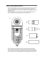
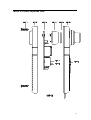
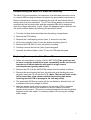
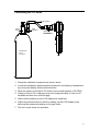
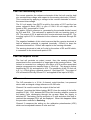
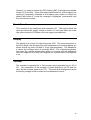
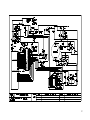
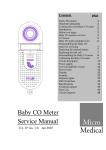
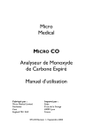
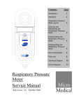
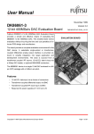
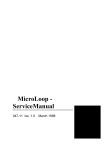
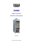
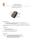
Contents
Safety Precaution
Important safeguards
Looking after your
Micro CO meter
Introduction
Before you begin
Micro CO meter
system Overview
CO sensor
Micro CO meter
exploded view
Disassembling the
Micro CO meter
for Servicing
Replacing the service
parts of the Micro CO
Reassembling the
Micro CO meter
Calibrating the
Micro CO meter
Circuit description
Specifications
Technical support
Parts List
Circuit Diagram
Micro CO Meter
Service Manual
037-16 Iss. 1.2 September 1998
page
2
2
2
2
2
3
5
6
7
7
8
9
10
13
14
15
17
Micro CO Meter
Service Manual
Information in this document is subject to change without notice and does not represent a commitment
on the part of Micro Medical Limited. Only the parts supplied by Micro Medical Limited should be used
to complete the service operation described in this manual. If in any way you feel unsure about the
successful completion of the service operation you should contact Micro Medical Limited or its
appointed agent in your country or region and arrange the despatch of the product to a Micro Medical
Limited Service Centre.
Copyright 1998 by Micro Medical Limited All rights reserved
Drawing no. 037-16
Version 1.2
September 1998
All other products are trademarks or registered trademarks of their respective owners.
1
Safety Precaution
The servicing of this device is intended to be carried out by a properly trained and
competent electronics engineer, or experienced in the maintenance and servicing
of medical devices. Read this manual thoroughly before proceeding with the
service. If in any doubt please contact the service centre at Micro Medical Limited
or their accredited agent in your country or region.
Important Safeguards
o Read all of the instructions.
o Keep the instructions in a safe place for later use.
o Follow all warnings and instructions marked on the product.
o When replacement parts are required, be sure to use replacement parts
specified by Micro Medical that have the same characteristics as the original
parts. Unauthorised substitutions may result in fire, electric or other hazards.
o Do not place on an unstable table.
o The product should be operated only from the type of power source indicated
on the label.
Looking after your Micro CO Meter
o Avoid exposing the Micro CO Meter to direct sunlight.
o Avoid operating the Micro CO Meter in dusty conditions or near to heating
appliances or radiators.
o Do not keep the Micro CO Meter in a damp place or expose it to extreme
temperatures.
Introduction
This service manual provides you with information to carry out the servicing of the
Micro CO Meter. It is a process, which is relatively straightforward but must be
carried out in a logical sequence. Our advice is to familiarise yourself with the
contents of this manual before attempting to carry out the procedure of replacing
the parts supplied in the sensor replacement kit for the Micro CO Meter.
Before You Begin
Before you begin the servicing operation, please read the section on Circuit
description very carefully:
2
Micro CO Meter system overview.
The Micro Medical Micro CO meter consists of a hand held microcomputer
unit (1) incorporating a CO sensor and is supplied with a mouthpiece
adapter with integral one way valve (2) together with disposable cardboard
mouthpieces (5).
The microcomputer unit is powered by a single alkaline PP3 battery (4)
and is supplied with a reducing connector for calibration (3).
The CO sensor is an electrochemical fuel cell, and works through the
reaction of carbon monoxide at one electrode and oxygen (from ambient
air) at the other. This reaction generates an electrical current proportional
to the concentration of CO exposed to the sensing surface of the fuel cell.
3
The current output signal from the sensor is conditioned using a current to
voltage converter and is applied to an analogue to digital (A/D) converter
inputs of the microprocessor.
When the unit is first switched on the microprocessor records the baseline
reading on the A/D input and uses this value to auto zero the instrument.
The subject is requested to breathe in maximally, hold the breath for 20
seconds, and then to expire fully through the mouthpiece connected to the
microcomputer unit with the mouthpiece adapter.
The microprocessor then records the peak value obtained and displays
this on a 3½ digit LCD display.
The value can be displayed either as parts per million (ppm) concentration
in the expired air or as the equivalent percentage carboxyhaemoglobin
(%COHb) using the mathematical relationships described by Jarvis et al,
for concentrations below 90ppm and by Stewart et al for higher
concentrations.
Jarvis MJ, Belcher M, Vesey C, Hutchison DCS
Low cost carbon monoxide monitors in smoking assessment .
Thorax 1986; 41:886-887
Stewart RD, Stewart RS, Stamm W, Seleen RP
Rapid estimation of carboxyhaemoglobin levels in fire fighters
JAMA 1976; 235:390-392
4
CO Sensor
The sensor is an electrochemical micro fuel cell using gaseous diffusion
barrier technology resulting in a direct response to volume concentration
rather than partial pressure as with other fuel cells.
The fuel cell uses a three electrode design which gives increased
selectivity to the measured gas compared with two electrode designs. The
three electrode cell consists of a sensing electrode, a counter electrode
and a reference electrode separated by a thin layer of electrolyte. The
gaseous diffusion barrier limits the flow of gas to the sensing electrode and
ensures the electrochemical activity of the electrode is far in excess of the
amount of gas with which it has to deal.
Gas diffusing onto the sensing electrode reacts at the surface of the
electrode by oxidation.
CO reacts at the sensing electrode according to the equation:
CO + H2O → CO2 + 2H+ + 2eThe counter electrode acts to balance out the reaction at the sensing
electrode by reducing oxygen in air to water:
½O2 + 2H+ + 2e- → 2 H2O
The CO fuel cell requires a bias voltage of 220mV to be supplied
permanently to the reference electrode.
The low power circuitry supplying this voltage, is powered by an internal,
950mA –hr lithium cell with an operational life greater than the life of the
electrochemical fuel cell.
5
Micro CO meter exploded view
6
Disassembling the Micro CO meter for servicing.
The Micro CO microcontroller unit comprises of a solid state electronic circuit
in a robust ABS housing and does not require any preventative maintenance.
Routine maintenance consists of replacing the fuel cell and internal lithium
battery when they are exhausted. The 3.6 volt lithium battery is continuously
monitored by the microcontroller and the message CEL will be displayed
when the voltage falls below 3 volts. When this happens replace both the fuel
cell and the lithium battery by following the procedure below.
1. Turn the unit face down and slide back the battery compartment.
2. Remove the PP3 battery.
3. Remove the 2 self tapping screws (Item 1) and put to one side.
4. Lift the top moulding (Item 6) from the bottom moulding (Item 2).
5. Remove the PCB (Item 3) from the bottom moulding.
6. Carefully remove the fuel cell (Item 4) and disregard.
7. Unsolder the lithium battery (Item 7) from the PCB and disregard.
Replacing Service parts of the Micro CO.
1 Solder the new battery in place (Cat No: BAT3700) (Take great care not
to short circuit the terminations even momentarily as the low internal
impedance of lithium batteries will result in a high current
consumption and greatly reduced life).
2 Remove the CO (Cat No: MCEL3700) sensor from the plastic container.
3 Remove the wire shorting link from the reference and shorting pins and
carefully insert the CO cell into the PCB. (Note: The fuel cell must not be
left for more than a few minutes without the shorting link before
inserting into the PCB or damage to the cell may result).
4 The assembled PCB must now be left for two weeks to allow the fuel cell
to stabilise at the bias voltage of 220mV.
5 After two weeks check that the output of the op-amp (IC3D) is between
180 and 220mV with the unit switched on and no carbon monoxide
present on the sensor (This can be measured between the two test points
adjacent to the slide switch. If necessary adjust VR1 to bring the voltage
within range.)
7
Reassembling the Micro CO meter
1. Place the PCB into the bottom moulding.
2. Ensure that the slide switch (Item 8) and the switch plate (Item 9) are both
positioned at the bottom of their travel.
3. Ensure that the O.ring (Item 5) supplied with the fuel cell is in place.
4. Place the top moulding on top of the bottom moulding and secure using
the two self tapping screws.
5. Reconnect the PP3 battery ensuring correct polarity.
8
Calibrating the CO meter
Plastic Tubing
Control
Valve
Flow
Indicator
Reducing
for Calibration
Connector
20-400ppm
CO in
Nitrogen
1. Setup the calibration equipment as shown above.
2. Locate the calibration potentiometer positioned in the battery compartment
by moving the battery without disconnection.
3. Slide the switch on the Micro CO meter to the middle position (CO-PPM)
4. Supply a flow of CO in Nitrogen at a rate of approximately 4 l/min for 25
seconds and then turn off the supply.
5. Wait until the reading on the LCD display has stabilised.
6. Adjust the potentiometer so that the reading on the LCD display is the
same as the measured reading on the gas bottle.
7. The unit is now ready for operation.
9
Circuit description
(Refer to parts list , and to circuit diagram 037-20)
The circuit is based on the Motorola one time programmable (OTP)
microcontroller MC68HC705C9ACP (IC1) operating at a clock frequency of 1
MHz.
This processor contains 7 Kbytes of EPROM, 176 Bytes of RAM,
programmable output latches, and a serial peripheral interface (SPI). The
current output signal from the sensor is conditioned using a current to voltage
converter and is applied to a 8 channel analogue to digital (A/D) converter
connected to a microprocessor. The calibration potentiometer is also
connected to the A/D converter.
When the unit is first switched on the microprocessor records the baseline
reading from the A/D and uses this value to auto-zero the instrument. The
signal from the CO sensor and the voltage from the calibration potentiometer
are both continuously monitored and the peak of the calculated carbon
monoxide concentration is displayed.
Power Supply
The unit has two separate supplies. The main supply is provided by the
externally accessible alkaline 9 volt PP3 battery (BAT 1). The instrument may
be switched on and off with the slide switch and may also be switched off by a
signal from the processor. This is done if the unit is left on, without use, for a
period of 5 minutes in order to conserve battery power. The supply is
controlled by gates A and B of IC2, arranged in a bi-stable configuration, and
powered continuously from BAT1. When the slide switch is moved to the
‘CO-PPM’ position one end of R23 is pulled low. This transition is
differentiated by the action of C12 and R22 so that a momentary pulse
appears on pin 9 of IC3. This pulse will toggle the bi-stable circuit so that pin
11 will go low, turning transistor TR3 on, and supplying 9 volts to the low dropout regulator, IC4. When the slide switch is returned to the ‘off’ position pin 13
of IC3 is pulled low, the bi-stable action is reversed, and TR4 will be turned
off. If the unit is left on without use for 6 minutes then pin 30 of IC1 is driven
high, under software control, turning on TR1 which will also turn the unit off
via the bi-stable circuit. When this happens the slide switch must be pushed
to the ‘off’ and then to the ‘CO-PPM’ position in order to initiate another pulse
through C12 to turn the unit back on again. The output of the 5 volt regulator
supplies the processor and associated circuitry. The input and output of IC4
is smoothed by C1 and C2 respectively.
The secondary power supply is provided by a single 3.6 volt lithium cell used
to permanently power the fuel cell conditioning circuit consisting of the opamps (IC5 and IC6), and the precision voltage reference (ZD1) together with
the associated passive circuitry. The conditioning circuit draws less than
72uA from the 950 mA-Hr lithium battery giving an operational life of 18
months.
10
Fuel cell conditioning circuit
For correct operation the reference electrode of the fuel cell must be held
at a constant bias voltage with respect to the sensing electrode (-220mV).
This is achieved by applying a voltage to the counter electrode to induce
the correct bias voltage.
The 3.6 volt supply from BAT2 is split by the action of R17 and the low
power reference diode (ZD1) to give a 2.34/-1.26 volt supply with the
anode of ZD1 connected to 0 volts.
The stable –220mV reference is, generated by the potential divider formed
by R18 and R19. This reference is applied to the non-inverting input of
IC5. The output of IC5 is applied to the counter electrode through R1. The
inverting input of IC5 is connected to the reference electrode through R2
and R3.
The negative feedback of this circuit ensures that the counter electrode is
held at whatever potential is required (nominally –350mV) to keep the
reference electrode at –220mV with respect to the sensing electrode.
The sensing electrode is held at 0 volts by the action of R5 and R6 which,
is connected to the virtual earth point of IC6.
Fuel cell amplifier circuit.
The fuel cell provides an output current, from the sensing electrode,
proportional to the concentration of target gas at the sensing surface. This
current is converted to a voltage by the action of IC6 and the associated
passive components at a transfer factor of 15mV/µA. This signal is further
amplified by IC3 (b) and applied to IC8. The sensitivity of the CO fuel cell
is 0.1 +/- 0.02µA giving a nominal output of 1.5mV/ppm CO. The output of
IC6 is filtered at 60Hz by R9 and C11 and applied to the input of IC3(B).
A/D converter
The A/D converter is a 10 bit, 8 channel, serial interface, low powered
device with an integral voltage reference of 4.096 volts.
Channel 0 is used to monitor the output of the fuel cell.
Channel 1 monitors the lithium battery (BAT2) from the output of the buffer
amplifier IC3(A). R16, between BAT2 and the inverting amplifier, prevents
the battery from discharging through the op-amp when the supply is
switched off. The battery has an end point of 3 volts and when this level is
reached the message CELL will be displayed. When this happens follow
the procedure outlined in Servicing.
Channel 2 measures the setting on the calibration potentiometer (VR2)
which can be adjusted between 0 volts and Vref.
11
Channel 3 is used to monitor the PP3 battery (BAT1) through the potential
divider, R13 and R14. When this battery falls below 6.6 volts a battery low
warning is temporarily indicated on the display upon switch on. When the
battery falls below 6.1 volts the message is displayed permanently and
the unit cannot be used.
Reset Circuit
This consists of the dedicated reset controller IC7. This device holds the
reset low whilst the supply voltage is below 4.5 volts and takes the reset
high after a period of 350msec once the supply has stabilised.
Display
The display is a custom 3½ digit low power LCD. The seven segments of
the three digits, the decimal point, the backplane and the blow legend are
driven directly by ports A,B and C of the microprocessor. The backplane
is driven by a square wave of nominally 60Hz. The individual segments
are driven by a similar square wave which is in phase with the backplane
when the segment is off and 180 degrees out of phase when the segment
is on.
Sounder
The sounder is operated by a 1kHz square wave generated by pin 35 of
IC1. One connection of the sounder is driven directly by pin 35 and the
other by the inverted signal from TR1. This push-pull arrangement raises
the driving voltage to the sounder and increases the volume
12
Specifications
Type
Micro fuel cell
Range
0 – 500ppm
Resolution
1ppm
Sensor Life
>1 year
Response time
<20 sec (to 90% of reading)
Hydrogen cross sensitivity <10%
Operating temperature
0 to 40°C
Operating pressure
Atmospheric +/-10%
Pressure coefficient
0.02% signal per mBar
Relative humidity
15 – 90% continuous
(Non condensing)
(0 – 99% intermittent)
Baseline drift
0ppm (auto zero)
Long term drift
<2% signal loss per month
Power source
Single Alkaline 9 volt PP3
Battery life
>30 hours of continuous use
Weight
160g
Dimensions
170 x 60 x 26mm
Display
3½ digit LCD
13
Technical Support
Great Britain and World Headquarters
Micro Medical Ltd
PO Box 6
Rochester
Kent ME1 2AZ
Telephone
+ 44 (0)1634 360044
Fax
+44 (0)1634 360055
Web Site
http://www.micromedical.com.uk
Email
[email protected]
Contact Micro Medical Ltd for the local agent in your region or
country for local service:
14
Parts List
Designation
IC1
IC2
IC3
IC4
IC5
IC6
IC7
IC8
D1
D2
ZD1
DISPLAY
TR1
TR2
TR3
R1
R2
R3
R4
R5
R6
R7
R8
R9
R10
R11
R12
R13
R14
R15
R16
R17
R18
R19
R20
R21
R22
R23
R24
R25
R26
R27
R28
R29
VR1
C1
C2
C3
C4
C5
C6
C7
Description
(MC68HC705C9ACP) MOTOROLA OTP MICROCONTROLLER
(4093) QUAD 2 INPUT NAND GATE
(TL27L2CP) DUAL LOW POWER OP-AMP
(LM2931AZ5) LOW DROP OUT LOW POWER 5 VOLT REGULATOR
(OP90GS) PRECISION MICRO POWER OP-AMP
OP90GS) PRECISION MICRO POWER OP-AMP
(DS1233-10) DALLAS ECONO RESET
(MAX186DCAP) 12 BIT SSOP SERIAL D/A OR (MAX192BCAP) 10 BIT A/D
(1N4148) GENERAL PURPOSE DIODE
(BAT42) GENERAL PURPOSE SCHOTTKY DIODE
(TC04BCZM) 1.26V BANDGAP REFERENCE
(LCD 016-03) 3½ DIGIT CUSTOM DISPLAY
(BC182LB) NPN TRANSISTOR TO92(A) PACKAGE ALTERNATIVE (BC182LC)
BC182LB) NPN TRANSISTOR TO92(A) PACKAGE ALTERNATIVE (BC182LC
(ZTX751) PNP TRANSISTOR E-LINE PACKAGE
1K SURFACE MOUNT RESISTOR 0.125 WATT 5% SIZE 1206
10K SURFACE MOUNT RESISTOR 0.125 WATT 5% SIZE 1206
10K SURFACE MOUNT RESISTOR 0.125 WATT 5% SIZE 1206
15K SURFACE MOUNT RESISTOR 0.125 WATT 5% SIZE 1206
10 OHM SURFACE MOUNT RESISTOR 0.125 WATT 5% SIZE 1206
1K SURFACE MOUNT RESISTOR 0.125 WATT 5% SIZE 1206
10K ¼WATT 5% RESISTOR
3.3K ¼WATT 5% RESISTOR
22K ¼WATT 5% RESISTOR
100K SURFACE MOUNT RESISTOR 0.125 WATT 5% SIZE 1206
10 OHM ¼WATT 5% RESISTOR
4.7M ¼WATT 5% RESISTOR
100K ¼WATT 5% RESISTOR
100K ¼WATT 5% RESISTOR
100K ¼WATT 5% RESISTOR
1M SURFACE MOUNT RESISTOR 0.125 WATT 5% SIZE 1206
100K SURFACE MOUNT RESISTOR 0.125 WATT 5% SIZE 1206
180K SURFACE MOUNT RESISTOR 0.125 WATT 5% SIZE 1206
820K SURFACE MOUNT RESISTOR 0.125 WATT 5% SIZE 1206
10K ¼WATT 5% RESISTOR
1MEG ¼WATT 5% RESISTOR
1MEG ¼WATT 5% RESISTOR
1MEG ¼WATT 5% RESISTOR
100K ¼WATT 5% RESISTOR
10K ¼WATT 5% RESISTOR
10K ¼WATT 5% RESISTOR
10K ¼WATT 5% RESISTOR
10K ¼WATT 5% RESISTOR
1.8MEG SURFACE MOUNT RESISTOR 0.125 WATT 5% SIZE 1206
(3266X-100K) 100K MULTI TURN POTENTIOMETER
47µF 16 VOLT ELECTROLYTIC CAPACITOR
47µF 16 VOLT ELECTROLYTIC CAPACITOR
47pF CERAMIC CAPACITOR
47pF CERAMIC CAPACITOR
47µF 16 VOLT ELECTROLYTIC CAPACITOR
47µF 16 VOLT ELECTROLYTIC CAPACITOR
0.1µF CERAMIC CAPACITOR
15
C8
C9
C10
C11
C12
C13
C14
C15
C16
SW1
BAT2
X1
1µF MULTILAYER CERAMIC CAPACITOR
0.1µF CERAMIC CAPACITOR
47µF 16 VOLT ELECTROLYTIC CAPACITOR
47µF 16 VOLT ELECTROLYTIC CAPACITOR
0.1µF CERAMIC CAPACITOR
47µF 16 VOLT ELECTROLYTIC CAPACITOR
0.1µF CERAMIC CAPACITOR
100pF CERAMIC CAPACITOR
1nF CERAMIC CAPACITOR
(SLF2300) DOUBL POLE 3 POSITION SLIDE SWITCH
(LS14250) SAFT PCB MOUNTED 950mA-HOUR LITHIUM CELL
4MHz CERAMIC RESONATOR
16
17