1
EST3 Synergy Enabled®
3-MODCOM
Self Study Course
P/N 3100340 • Original • 09JULY01
DEVELOPED BY
Edwards Systems Technology
6411 Parkland Drive
Sarasota, FL 34243
(941) 739–4203
COPYRIGHT NOTICE
Copyright © 2001 Edwards Systems Technology, Inc.
This manual and the products it describes are copyrighted by
Edwards Systems Technology, Inc. (EST). You may not
reproduce, translate, transcribe, or transmit any part of this
manual without express, written permission from EST.
This manual contains proprietary information intended for
distribution to authorized persons or companies for the sole
purpose of conducting business with Edwards Systems
Technology, Inc. If you distribute any information contained in
this manual to unauthorized persons, you have violated all
distributor agreements and we may take legal action.
TRADEMARKS
Microsoft is a trademark of Microsoft Corporation.
Microsoft Mouse is a trademark of Microsoft Corporation.
Windows is a trademark of Microsoft Corporation.
CREDITS
This course was developed and written by the EST Technical
Institute in conjunction with the Documentation Department,
Sarasota.
DOCUMENT HISTORY
Date
Revision
Reason for change
09JULY01
1.0
Initial release
Content
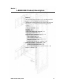
Module 1
3-MODCOM Product Description • 1.1
Introduction to module 1 • 1.2
Key items • 1.4
Objectives • 1.5
3-MODCOM/3-MODCOMP Overview • 1.6
Configuring the MODCOM • 1.13
MODCOM Dialer Transmission Process • 1.14
Programming the MODCOM • 1.18
MODCOM Installation Considerations • 1.36
Module 1 evaluation • 1.40
Module 2
Configuring the MODCOM • 2.1
Introduction to module 2 • 2.2
Key items • 2.3
Objectives • 2.4
Entering the MODCOM into a Project • 2.5
Configuring MODCOM General Operating Parameters • 2.9
Configuring MODCOM Receiver Properties • 2.16
Configuring MODCOM Account Properties • 2.25
Module 2 evaluation • 2.31
Module 3
MODCOM Communication Protocols • 3.1
Introduction to module 3 • 3.2
Key items • 3.3
Objectives • 3.4
Supported Message Protocols • 3.5
Contact ID Coded Messages • 3.7
SIA DCS Coded Messages • 3.18
SIA P2 (3/1) and SIA P3 (4/2) Coded Messages • 3.26
TAP Protocol Coded Messages (Pager Applications) • 3.28
Module 3 evaluation • 3.33
Module 4
Programming MODCOM Applications • 4.1
Introduction to module 4 • 4.2
Key items • 4.3
Objectives • 4.4
General Fire Alarm MODCOM Dialer Applications • 4.5
Module evaluation • 4.16
MODCOM Self-Study Course
i
Content
Important information
Limitation of liability
This product has been designed to meet the requirements of
NFPA Standard 72, 1993 Edition; Underwriters Laboratories,
Inc., Standard 864, 7th Edition; and Underwriters Laboratories
of Canada, Inc., Standard ULC S527. Installation in accordance
with this manual, applicable codes, and the instructions of the
Authority Having Jurisdiction is mandatory. EST shall not under
any circumstances be liable for any incidental or consequential
damages arising from loss of property or other damages or losses
owing to the failure of EST products beyond the cost of repair or
replacement of any defective products. EST reserves the right to
make product improvements and change product specifications
at any time.
While every precaution was taken during the preparation of this
manual to ensure the accuracy of its contents, EST assumes no
responsibility for errors or omissions. Features described in this
manual are subject to change without notice.
FCC warning
This equipment can generate and radiate radio frequency energy.
If this equipment is not installed in accordance with this manual,
it may cause interference to radio communications. This
equipment has been tested and found to comply within the limits
for Class A computing devices pursuant to Subpart B of Part 15
of the FCC Rules. These rules are designed to provide
reasonable protection against such interference when this
equipment is operated in a commercial environment. Operation
of this equipment is likely to cause interference, in which case
the user at his own expense, will be required to take whatever
measures may be required to correct the interference.
ii
MODCOM Self-Study Course
Content
EST3 Self-Study Course introduction
Welcome to Edwards Systems Technology’s EST3 Synergy
Enabled® 3-MODCOM Self-Study Course. This course is
designed to train you, the technician, in component
identification, function, installation and programming practices
for the 3-MODCOM and 3-MODCOMP. The materials for this
course include:
• EST3 Self-Study Course Manual (p/n3100340)
• EST3 Installation and Service Manual, P/N 270380, Rev 4.0 or
later.
This self-study course is also designed to facilitate your use of
the EST3 technical reference manuals and the SDU HELP
Utility. While taking this course, keep the manuals close by, as
you will be referred to them on frequent occasions. You will
also need to update your 3-SDU to version 3.0 or greater. You
will be required to create a practice project during this lesson.
The course consists of four modules covering the 3-MODCOM
components and their installation, its configuration, developing
message protocols, and programming the MODCOM as a dialer
for General Fire Alarm applications. The modules were designed
for use in a logical progression. Accordingly, study them in the
order in which they are presented.
To answer any questions or concerns encountered while studying
these modules, you can contact a course instructor at the EST
Training Department.
Upon completion of this entire self-study course take the online
module examination at our WEB Site.
MODCOM Self-Study Course
iii
Content
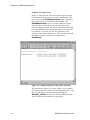
Simply go to www.EST.net, select Training, sign-in, select
online training, select Self-Study Testing and select
3-MODCOM Self-Study Test (P/N 3100329).
During this test the SDU Online Help is available for your
reference while you are taking the test. Simply click on the help
button to launch Help at any time.
An average grade of 85 for this online test is required for
successful completion. Upon satisfactory completion, you are
qualified to purchase the 3-MODCOM and 3-MODCOMP
Modem Communicator module and to develop applications
using these products.
The scope of this self-study is for Fire Alarm system only
applications of these products. Using the MODCOM products in
more sophisticated integrated fire, security and access control
applications is covered in the factory based EST3 Synergy
Enabled® Certification Course. Checkout the quarterly training
schedule on our Web Site for the available of this course.
iv
MODCOM Self-Study Course
Content
Mail any correspondence to:
Edwards Systems Technology
Training Department
6411 Parkland Drive
Sarasota, FL 34243
Our FAX number is: (941) 755-7387
To talk to an instructor, please call (941) 739-4304.
Caution: Use caution when using this course material as a
reference manual after completing the course. Changes and
additions to EST3 will continue for the life of the product. These
will be added to the EST3 technical reference manuals in
periodic revisions. Your course material will NOT receive these
revisions. The Installation Sheets received with hardware
will contain the most current information.
Course Prerequisites:
• You must be EST3 certified and have the 3-SDU, version 3.0
or greater installed on your PC.
• You should have a basic understanding Fire Alarm dialer
applications.
MODCOM Self-Study Course
v
Content
vi
MODCOM Self-Study Course
Module 1
3-MODCOM Product Description
Summary
This self-study module introduces you to the Integrated EST3
System’s 3-MODCOM and 3-MODCOMP Modem
Communicator modules and provides a general description of
their features, requirements, installation and applications.
Content
Introduction to module 1 • 1.2
Key items • 1.4
Objectives • 1.5
3-MODCOM/3-MODCOMP Overview • 1.6
Configuring the MODCOM • 1.13
MODCOM Dialer Transmission Process • 1.14
Programming the MODCOM • 1.18
The Command List • 1.22
The Command Qualifiers • 1.25
Numerical Indexing or N-Variables • 1.26
Substitution Strings • 1.28
Hexadecimal Indexing or H-Variables • 1.32
MODCOM Installation Considerations • 1.36
Telephone Line Requirements • 1.36
Installing the MODCOM Module • 1.37
Connecting the MODCOM to the TELCO Lines • 1.39
Module 1 evaluation • 1.40
MODCOM Self-Study Course
1.1
3-MODCOM Product Description
Introduction to module 1
The 3-MODCOM and 3-MODCOMP Modem Communicators
incorporate modem and dialer functions into the integrated
EST3 system architecture. These EST3 modules are Local Rail
Modules (LRMs) that employ the snap-fit technology used for
the other EST3 LRMs. These MODCOM LRMs easily install
on the chassis rail slots in the EST3 cabinet enclosures.
The 3-SDU, version 3.0 or greater enables you to develop fully
integrated Fire, Security and Access Control system
applications. The integrated EST3 system architecture employs
the MODCOM LRMs as:
·
A modem to download and maintain Access Control and
Keypad Display data into the integrated EST3 system.
·
A dialer to report Fire, Security and Access Control
premises events to a Central Station monitoring service
and/or pager.
This self-study module is the 3-MODCOM and 3-MODCOMP
product description, which describes the features and
capabilities of both MODCOM types. This module also
describes MODCOM operation, describes MODCOM
installation considerations, and introduces you to the basic
MODCOM configuration and programming process required to
incorporate the MODCOM into an integrated EST3 system
environment.
This self-study course is designed for those who are EST3
certified for fire alarm systems. Successful completion of this
MODCOM self-study course results in certification, which
enables you to purchase the MODCOM products and
incorporate them into your EST3 applications using the 3-SDU
version 3.0 or greater.
The 3-MODCOM and 3-MODCOMP products are also taught as
part of a factory course on EST3 Synergy Enabled® Access
Control and Security products. You can find a description of
this factory course on our web site (www.EST.net) as EST3
Synergy Enabled® Certification Course (P/N 3100330).. If you
intend to use these integrated Access Control and Security
products you need to attend this factory course to gain
certification.
1.2
MODCOM Self-Study Course
3-MODCOM Product Description
Associated study
Prior to starting this course you should update your SDU to
version 3.0. This will make the SDU’s onboard Help Utility
available to you as a training aid. Prior to starting this course go
to the Help Utility, select the Search tab, search on MODCOM
and review the related MODCOM help files. Remember that
you can print out the file for review if you desire a paper copy.
Use the following technical reference manuals as associated
study material for this module:
•
•
•
EST3 Installation and Service Manual, P/N 270380, Rev 4.0 or
later)
EST3 System Operations Manual, (P/N 270382, Rev 4.0 or later)
Modem Communicator 3-MODCOM/3-MODCOMP Installation
Sheet, (P/N 387476)
Copies of these manuals and the 3-SDU’s Help Utility are also
available on the Fire Alarm Support Tools, Online Support
System CD (P/N 270395, Rev 5.0 or later).
This Online Support System CD and its onboard Help Utility are
useful tools. The minimum system requirements for your PC or
laptop are:
•
•
•
•
•
IBM compatible Pentium computer
SVGA monitor (800 x 600 pixel at 256 color)
Windows 95 or greater
2X CD-ROM drive
Current version of Acrobat Reader, which is available on this
CD.
This CD also contains all the product installation sheets
available as of its date of publication. It would be impossible for
EST to maintain these installation sheets at their current
revisions on the CD or in the published manuals. The CD and
manuals are updated only when major changes to the system are
made. The actual installation sheets, shipped with the product
components, reflect the current revision levels. It would be good
practice to maintain a current set of these installation sheets on
site and/or at your office.
It may also be helpful to develop a practice project in the 3-SDU
during this self-study course. This will enable you to refine your
skills at developing MODCOM applications and become
familiar with the SDU tools.
MODCOM Self-Study Course
1.3
3-MODCOM Product Description
Key items
Key points to look for:
•
•
•
•
•
•
•
•
•
•
•
•
•
•
3-MODCOM/3-MODCOMP modem function.
3-MODCOM/3-MODCOMP dialer function.
Downloading EST3 application data.
Premise event reporting to a monitoring service.
Any Ring, Normal Ring, Long-Long Distinct Ring, ShortShort-Long Distinct Ring, Short-Long-Short Distinct Ring
detection and answering modes.
Required RJ-31X and RJ-38X telephone jacks.
One/Two loop start line or public switched telephone line
compatibility.
Bell 103 and V.32 compliant 14.4 K-baud modem.
1-Line Dialer, 2-Line Dialer, Modem, 1-Line Dialer with
Modem and 2-Line Dialer with Modem MODCOM
applications are supported.
Contact ID, SIA DCS, SIA P2 and SIA P3 Central Station
Communication Protocols are supported.
TAP Pager Protocol is supported in 3-MODCOMP.
General, Zoned and Point ID Central Station event reporting
is supported.
Called Party Disconnect service requirement to prevent
jamming from incoming calls.
Preset default NFPA 72 Certified Fire Alarm and Burglary
System compliance operation.
Key terms and components to learn:
•
•
•
•
•
•
•
•
•
•
•
1.4
Receivers
Accounts
Command List
Command Qualifiers
Activation Event
Activate Command
Restore Command
Send Command
Command Qualifiers
Substitution Strings
Hexadecimal Indexing
MODCOM Self-Study Course
3-MODCOM Product Description
Objectives
Upon completion of this module you will be able to:
1. Identify the 3-MODCOM and 3-MODCOMP modules.
2. Determine the various MODCOM, telephone line and
Central Station requirements for your application.
3. Describe the basic transmission/communication process for
the MODCOM dialer.
4. Describe NFPA 72 compliance requirements for MODCOM
applications.
5. Describe the purpose of configured MODCOM receivers
and accounts.
6. Describe the basic programming function of a command list,
send command, command qualifier, numerical indexing,
hexadecimal indexing and substitution strings.
7. Physically install the 3-MODCOM and 3-MODCOMP into
an EST3 cabinet enclosure.
MODCOM Self-Study Course
1.5
3-MODCOM Product Description
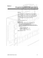
3-MODCOM/3-MODCOMP Overview
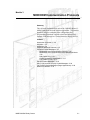
Figure 1-1: A 3-MODCOM Modem Communicator LRM
with Control/LED Display module.
The 3-MODCOM and 3-MODCOMP Modem Communicators
are Digital Alarm Communicator/Modem modules which
incorporate modem and dialer functions into the EST3 system
architecture. These modules are optional EST3 Local Rail
Modules, which easily install into an expansion slot in an EST3
cabinet enclosure.
The 3-MODCOM Modem Communicator integrates onboard
modem and dialer capabilities into the EST3 system
environment. As a modem, the 3-MODCOM enables the
downloading of information (such as, access control and keypad
display applications data) into the EST3 system from a remote
site (e.g. from an end-user’s PC).
1.6
MODCOM Self-Study Course
3-MODCOM Product Description
As a dialer, the 3-MODCOM sends alarm, supervisory and
trouble information to a remote site (e.g. Central Station) using
one or two phone lines. This information can be reported in a
dual or split format.
Note: The 3-MODCOM dialer is used for event reporting to a
monitoring station called a Central Monitoring Station (CMS).
During this self-study course we will use the term Central
Station, CMS or Central Monitoring Station interchangeably.
Where Central Monitoring Station is the formal terminology and
Central Station is conversationally more popular.
The 3-MODCOMP Modem Communicator provides the same
modem/dialer functions as the 3-MODCOM with the addition of
also sending information to individually predefined pagers.
Both the 3-MODCOM and 3-MODCOMP are standard type,
single-slot LRMs, which support mounting any of the four EST3
Control/LED display modules as shown in Figure 1-1.
These MODCOMs are shipped with two 7 foot, 8-position flat
telephone cables with an 8-position modular plug on both ends
(P/N 3601377). Line supervision is configurable for both
MODCOM phone lines, where line supervision may be enabled
or disabled for each phone line.
One end of each cable plugs directly into the two jacks at the top
of the MODCOM (shown in Figure 1-2 and Figure 1-3). The
other end of each cable plugs directly into a corresponding
RJ31X or RJ38X telephone jack, which is obtained locally and
wired to a switched telephone network. In Canada use CA31A
or CA38A telephone jacks.
CAUTION: Failure to use an RJ31X or RJ38X jack violates
FCC and NFPA regulations. A telephone connected directly to
an incoming phone line can cause TELCO trouble and can
possibly prevent the dialer from connecting to the Central
Station during an emergency.
These jacks must be installed within 5 feet of the cabinet that
houses the MODCOM. Note that each MODCOM phone line
has an LED to annunciate line ringing and data exchange.
Both MODCOM modules are compatible with one/two loop
start line on public switched telephone network, with pulse or
touch-tone (DTMF) dialing. Both MODCOM modules have an
onboard Bell 103 and V.32 bis compliant, 14.4K-baud modem.
MODCOM Self-Study Course
1.7
3-MODCOM Product Description
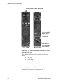
Two 8-position modular phone plugs
J1 Control/LED
display panel
ribbon cable
connection
BACK VIEW
DS1 and DS2
LEDs annunciate
line ringing and
FRONT VIEW data exchange
Figure 1-2: A 3-MODCOM Modem Communicator LRM
front and back views.
These MODCOM modules can be configured to detect and
answer:
·
Any Ring.
·
Normal Ring.
·
Long-Long Distinct Ring.
·
Short-Long-Short Distinct Ring.
·
Short-Short Long Distinct Ring.
Only MODCOM phone line 1 (J 20) contains a ring detection
circuit and can be used to receive incoming calls.
1.8
MODCOM Self-Study Course
3-MODCOM Product Description
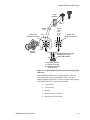
Surge
Protector
TIP
(Green)
Phone
Line 1
RJ31X 8-pin
Modular Connector
Phone
Line 2
(Wired
same as
Phone
Line 1)
Yellow
3
4
5
6
3
4
RJ31X 8-pin
Modular Connector
5
6
2
7
2
7
1
8
1
8
Black
Premises
Phones
Supplied 7-foot, 8-position
flat telephone phone
cables (P/N 3601377)
J20
J21
J20 and J21 positions
are based on viewing
the MODCOM module
from the front
Figure 1-3: Typical MODCOM interconnection using RJ31X
connectors.
These MODCOM modules are not plug-and-play. They are
easily configurable and programmable to meet a variety of
modem and dialer applications. You can configure and program
either MODCOM for the following applications:
MODCOM Self-Study Course
·
1-Line Dialer.
·
2-Line Dialer.
·
Modem.
·
Modem with 1-Line Dialer.
·
Modem with 2-Line Dialer.
1.9
3-MODCOM Product Description
Both MODCOM types support the following transmission
protocols:
Contact ID, which consists of numeric codes with several
optional parameters, such as:
[EventCode][Partition][DeviceNumber][User]
SIA DCS, which consists of ASCII Text codes with several
optional parameters, such as:
[Date][Time][UserID][AlarmCode][Device][User][Partition]
SIA P2 (20 pulses/round 3/1), which consists of numeric codes
of four digits, containing a 1-digit alarm code:
[AlarmCode]
SIA P3 (4/2 double round), which consists of 2-digit numeric
event codes:
[EventCode]
The 3-MODCOMP also supports Telelocator Alphanumeric
Protocol (TAP) for pager applications. TAP consists of two
fields of up to 59 characters separated by a carriage return (CR):
[UserID] CR [ASCCI Text Message]
where the message is generally the event type and device
location within the protected facility.
Note: In all cases, the Account Code would be part of the
transmission to the Central Station or Pager Service.
In addition to its role as a dialer performing status transmissions
to a Central Station, the dialer provides a modem, which can
receive application data from remote PCs. This mode enables
you to download keypad display and access control application
data into the integrated EST3 system. The MODCOM receives
data from the remote source over the phone lines and transfers it
to the 3-CPU1. The 3-CPU1 then distributes the appropriate
data to the Card Reader Controller and Keypad Display modules
via the 3-SAC module and SAC bus of the cabinet you are
connected to and over the EST3 Network Data Riser to other
nodes with 3-CPU1 and 3-SAC module configurations.
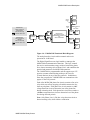
Figure 1-4 shows a 3-MODCOM functional block diagram when
installed into an EST3 system. This drawing may aid in your
understanding of the MODCOM operating capabilities.
The MODCOM microprocessor handles all handshaking and
data transfers over the rail to and from the 3-CPU1. This
microprocessor contains static and flash RAM and provides the
platform for the MODCOM microcode and database
applications software.
1.10
MODCOM Self-Study Course
3-MODCOM Product Description
3-CPU1
Class A
Return
3-CPU1
RS-485
Rail
Phone Line 1
Voltage, Current and
Ring Detection
with Line Seize Realy
RX
AMP
8-Position Phone Jack
Phone Line 2
Hook Switch
and
Gyrator Ckt.
Voltage and Current
Detection
with Line Seize Realy
8-Position Phone Jack
Line
XFORMER
TX
AMP
Network Data Riser
to
other Nodes
3-CPU1
3-LCD
MicroProcessor,
Digital Signal Processor,
14.4K Baud Analog Interface Ckt.
and
Static and Flash RAM
3-SAC
3-KPDISP
SAC Bus
CRC
Figure 1-4: 3-MODCOM Functional Block Diagram.
The analog Interface circuit enables transmit and receive
operations at 14.4K baud.
The Digital Signal Processor logic handles or manages the
MODCOM telecommunication functions. This logic controls
the receiver and transmitter amps, switches between the phone
lines, detects incoming calls on Phone Line 1 and establishes the
protocol and parameters for MODCOM operations.
The 3-MODCOM is programmable and can support up to 255
premise accounts communicating with up to 80 receivers
(Central Stations) in any of the four protocols. In addition to
these four protocols the 3-MODCOMP can communicate with
pagers via the TAP protocol.
Each of the MODCOM phone line circuits contains a line seize
relay which cuts off any ongoing call and disconnects the line
from any telephone. Each phone line circuit contains a < 10V
voltage detection circuit to determine loss of the phone line
during on-hook periods. Each phone line circuit also contains a
<10 mA current detection circuit to determine loss of the phone
line during off-hook periods.
Note: Only Phone Line 1 (J20) has a ring detection circuit to
detect incoming calls, which initiate a connection.
MODCOM Self-Study Course
1.11
3-MODCOM Product Description
Up to 10 MODCOM modules can be installed within a
networked EST3 system. These can be in a single node or
distributed throughout the network nodes. Multiple MODCOMs
are used to provide redundant communications with the Central
Station, as a backup for critical communications links and/or to
provide dedicated security transmission hardware.
When using multiple MODCOMs for redundant
communications both are configured and programmed to
transmit the same messages to different receivers at a Central
Station or to different receivers at different Central Station
locations.
MODCOM modules can be configured and programmed to
backup one another. In this way, Central Station or paging
(TAP) communications is guaranteed. Using backup configured
MODCOM modules enables you to create a dynamic failover
operation. This means that when a communication failure or
trouble occurs on one of the MODCOMs, the EST3 system
switches from accounts on the MODCOM in trouble to
matching accounts on its backup MODCOM.
A dedicated Central Station dialer MODCOM can be configured
and programmed in multiple tenant integrated system
applications where there may be a high volume of Access
Control and Keypad Display modem traffic. In this case, the
first MODCOM may be used for this modem communications
(Access Control and Keypad Display Data) and the second may
be used for Central Station dialer communications.
1.12
MODCOM Self-Study Course
3-MODCOM Product Description
Configuring the MODCOM
You use the 3-SDU System Definition Utility to create the
required configuration parameters, properties and data for the
specific application where the MODCOM is to be used. After
the MODCOM configured database is completed in the 3-SDU,
you convert it to a binary file and download it into the
appropriate MODCOM.
CAUTION: The 3-MODCOM and 3-MODCOMP modules are
configured and programmed using EST3 3-SDU version 3.0 or
higher. Do not attempt to use these modules with earlier
versions of the SDU or with non-compatible 3-CPU1 microcode.
Once configured, the MODCOM database application is stored
in the 3-MODCOM and 3-MODCOMP nonvolatile memory.
This database determines the operational parameters for your
application’s 3-MODCOM or 3-MODCOMP. Such as, phone
line properties, receiver attributes, and account parameters. This
database includes transmission details, such as telephone
numbers and dialing options.
In fully integrated applications supporting fire, security and
access control some security and access control data is
downloaded to and stored onboard the MODCOM.
As previously stated, the 3-MODCOM and 3-MODCOMP can
be configured as a 1-line dialer, 2-line dialer, modem only,
modem and 1-line dialer, or modem and 2-line dialer.
WARNING: For UL listed fire and FM approved installations,
the MODCOM must be configured as a 2-line dialer, where both
lines have line cut detection supervision.
The 3-MODCOM and 3-MODCOMP operate in accordance
with the configuration database and rules program downloaded
into the networked system’s 3-CPU1’s. Telephone numbers,
dialing details, activation of the dialer test signal, and other
MODCOM parameters are configured data which must be
downloaded into the MODCOM for proper operation for your
specific application.
In order for the MODCOM to electronically dial the Central
Station, specific dialer parameters must also be configured in the
3-SDU. These include whether you are using pulse or tone
dialing, the Central Station telephone number(s), and periodic
test transmission parameters required for fire alarm installations.
After the configuration process is complete, the SDU provides
you with a report of all Central Station codes on an account
basis that can be transmitted from the MODCOMP. This report
should be given to the appropriate Central Station.
MODCOM Self-Study Course
1.13
3-MODCOM Product Description
MODCOM Dialer Transmission Process
The multiple MODCOM, multiple phone line and multiple
telephone features of the 3-MODCOM and 3-MODCOMP
provide a high level of transmission integrity. The MODCOM
is designed to ensure that the call to the Central Station gets
through.
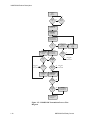
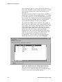
Figure 1-5 shows a flow diagram of the Dialer Transmission
Process. The sequence for MODCOM to Central Station
communications follows:
1. When an event occurs within the EST3 system that is to be
reported to the Central Station, the MODCOM seizes one of
the predetermined telephone lines.
2. The MODCOM puts the seized line on-hook for three
seconds to cut off any ongoing call and to disconnect the
line from any telephone or dialing device that may be
connected down-line.
Note: The MODCOM makes two attempts to select an unused
line before seizing a line already in use.
3. The MODCOM takes the seized line off-hook and waits for
a dial tone. If a dial tone is not detected within a
predetermined time established during configuration, the
MODCOM puts the line on-hook, increments an attempt
counter and continues to alternate lines and preconfigured
phone numbers until a dial tone is detected.
For example, if the MODCOM has been configured with two
telephone numbers and only one telephone line, it makes four
attempts to connect using the first number then four attempts
using the second number. This alternation between these two
telephone numbers continues until a connection is made or
preconfigured maximum number of attempts has been achieved.
Note: The DS1 and DS2 LEDs light steady during the off-hook
periods when data is not being transferred.
4. After achieving a connection (dial tone detection), the
MODCOM dials the Central Station using the
preprogrammed and preconfigured dialing mode and
telephone number.
5. The MODCOM then waits 40 seconds for a handshaking
message from the Central Station indicating that a
connection with the Central Station has been achieved.
1.14
MODCOM Self-Study Course
3-MODCOM Product Description
6. If handshaking is not received within the 40-second period,
the MODCOM puts the line on-hook, waits for a
preconfigured period of time and then repeats steps 3
through 5. If handshaking is detected the MODCOM
proceeds to step 9.
7. If the MODCOM is still unable to contact the Central
Station receiver within a second 40-second period it seizes
the other telephone line and makes two attempts to detect
handshaking on it.
8. If the MODCOM is still unable to contact a Central Station
receiver, it reseizes the first telephone line and repeats the
two attempts to reach the Central Station receiver using a
preconfigured secondary telephone number. If handshaking
is detected the MODCOM proceeds to step 9.
Note: If the MODCOM is still unable to contact the Central
Station receivers, it repeats steps 6 through 8, alternating
telephone lines and numbers until a preconfigured number of
attempts is achieved. On detecting the maximum number of
attempts the MODCOM sends a trouble message to the EST3
system’s 3-CPU1.
Note: The MODCOM retries the full number of attempts if
another event occurs or one attempt for the existing event if the
preconfigured Wait Time On-Hook Between Attempts To
Same Number period expires.
9. When a connection is completed, ringing is detected by the
Central Stations dialer receiver, which goes off-hook and
transmits the required handshaking.
10. If the handshaking received by the MODCOM matches the
preconfigured format, the MODCOM transmits all premises
event data in the predetermined format (Contact ID, SIA, 4/2
or 3/1).
Note: The DS1 and DS2 LEDs flash rapidly during data
transmissions.
11. The MODCOM then waits for acknowledgement and shut
down signal handshaking (called a KISSOFF) from the
Central Station receiver. On receiving this KISSOFF
handshaking the MODCOM puts the telephone line onhook, ending the call.
Note: The DS1 and DS2 LEDs extinguish.
MODCOM Self-Study Course
1.15
3-MODCOM Product Description
Predefined
Event
Activation
NO
Unused
Line
?
NO
YES
Second
Attempt
?
YES
Seize
Predetermined
Telephone Line
Put line On-hook
for 3 seconds to
disconnect
ongoing calls
Put line Off-hook
and
check for Dial Tone
for configured period
Dial
Tone
?
NO
Put line On-hook
and
increment
attempt counter
Alternate Line
or Phone Number
and
try again
YES
Increment
Attempt Counter
and
Wait Time Between
Attempts
Dial Central Station
and
Wait 40 seconds
for handshaking
NO
Second
Try
?
NO
Maximum
Attempts
?
NO
Alternate Line
or Phone Number
and
try again
NO
YES
Handshaking
Received
?
YES
Send Trouble YES
to
3-CPU1/3-LCD
Maximum
Attempts
?
Send Trouble
to
3-CPU1/3-LCD
YES
NO
Handshaking
Match
?
Send Trouble
to
3-CPU1/3-LCD
YES
MODCOM
Transmits premises
event data to
Central Station
KISSOFF
NO
Acknowledged
?
YES
YES
Confirmation
Command
List
?
Execute
Confirmation
Rule on Activation
of Command List
NO
MODCOM
puts line on-hook,
ending call.
Figure 1-5: 3-MODCOM Transmission Process Flow
Diagram.
1.16
MODCOM Self-Study Course
3-MODCOM Product Description
12. In the more sophisticated Access Control and Security
integrated applications it is sometimes desired to initiate
premise notification (security alarm) after the Central
Station has confirmed receipt of the event. In this way, the
Central Station can respond to the event before possible
warning the intruder. In this case, you would have
configured a Command List object for this KISSOFF
confirmation. You would then write a rule where this
Confirmation Command List would activate on receipt of
KISSOFF (dotted lines). This Confirmation Command List’s
activation would then execute the rule for premise
notification.
Advanced Access Control and Security applications are beyond
the scope of this self-study course and are covered in the EST3
Synergy Enabled® Certification course. For this lesson which is
for fire only applications, on receiving this KISSOFF
handshaking, the MODCOM puts the telephone line on-hook,
ending the call.
MODCOM Self-Study Course
1.17
3-MODCOM Product Description
Programming the MODCOM
As previously stated, the 3-MODCOM and 3-MODCOMP
modules are very flexible dialer/modem modules used to support
a wide variety of applications. These modules are not plug-andplay and require some level of preconfiguration and
programming to support your specific modem/dialer
requirements. Before attempting to configure and program the
MODCOM you should communicate with the Central Station to
gather the required parameters and protocol requirements before
you begin using the 3-SDU.
In the case of dialer applications, you need to identify the level
of event reporting for your application. For this self-study
course we will discuss three levels of event reporting to a
Central Station.
The first is GENERAL reporting which is basic and the
simplest event reporting method. In this case, event reporting is
normally limited to fire-only applications and the following
events are reported:
1. General alarm activation and restoration.
2. General supervisory activation and restoration.
3. General trouble activation and restoration.
Note: Phone line troubles, AC power failure troubles, etc. are
reported as a general troubles to the Central Station. If more
detailed trouble event reporting is desired you will need to use
ZONE or POINT reporting techniques. When the AC Power
Delay is configured, an AC Power Failure event will report after
the preset delay, but only as a general trouble.
4. Low Battery or Dead Battery Trouble (pseudo point
BATT_TRBL_CC_SS) activation and restoration.
Where CC is the cabinet address and SS is the
monitor module slot location.
5. Communication Trouble activation and restoration.
Note: This Communication trouble is not a MODCOM pseudo
point listed in the SDU objects. Comm Trouble reporting is built
into the MODCOM microcode software and all you need to do
is create the coded event message to be sent.
In security applications to report Security Perimeter, Security
Interior, and Holdup alarms you will need to use ZONE or
POINT reporting techniques.
1.18
MODCOM Self-Study Course
3-MODCOM Product Description
In general reporting you simply report the event code to the
Central Station and are not required to report ZONE or POINT
events. What is important here is to resolve MODCOM
operating parameters and Central Station receiver, account,
telephone line/number, and communications protocol issues
before the configuration and programming process begins.
The second method is ZONE reporting. In this case, the
premises reporting to the Central Station is subdivided into
zones or areas. You are required to support event reporting
similar to that described for general, but this time on a zone-byzone or area-by-area basis. Now when you report the event code
to the Central Station you would send the event code and a zone
or area identifier (location) code.
The third method is POINT reporting. This method requires
that enhanced communication protocols be used. In this case,
the MODCOM must report the event status and identity of every
device or point within the premises. This method is called point
reporting because every point within the system that goes into
fire Alarm, security Alarm, trouble or supervisory activation and
the restoration of each can be reported to the Central Station.
This reporting would be in the order of occurrence and priority.
Now when you report the event code to the Central Station you
would also send a system point identification code.
Note: The more sophisticated ZONE and POINT event reporting
methods are beyond the scope of this self-study course. These
methods are presented in the EST3 Synergy Enabled®
Certification Course.
In any of the three methods of event reporting the MODCOM
must be configured to support the required operation and rules
must be written to report event activation and restoration to the
Central Station.
You will also need to specify Central Station receivers, accounts
and telephone numbers prior to programming your application.
A Central Station receiver is the logical destination at the
Central Station to which the MODCOM must connect and
subsequently transmit event status messages to. A Central
Station may have many receivers in operation, each capable of
receiving many calls. The Central Station will determine which
receiver and telephone number you use for each account.
MODCOM Self-Study Course
1.19
3-MODCOM Product Description
During the configuration process you will need to:
·
Label each receiver specified.
·
Create a description of each receiver’s purpose.
Note: For Central Station purposes, the telephone number used
to gain access to a specified receiver basically identifies the
receiver. It may be critical to your application to enter relevant
Central Station information for the receiver being configured in
this description field for your reference.
·
Configure telephone line properties.
·
Enter your dial-in telephone number.
·
Enter the auto-answer ring cycle count.
·
Enter the wait time to detect dial tone.
·
Enter the wait time for calling party disconnect.
·
Enter the wait time for line cut monitor sensing.
·
Enter the primary and secondary Central Station
receiver telephone numbers.
·
Identify the protocol used for event reporting.
·
Enter the maximum number of dial attempts.
·
Enter the on-hook wait time between dial attempts.
An account within the MODCOM links the end user to a
specific Central Station receiver, identifying the user site
sending the event code and the Central Station to which the
message is being sent. Each event message sent by the
MODCOM includes an account number. During the
configuration process you will need to:
·
Label each account specified.
·
Create a description of each account.
·
Specify by label the Central Station where this
account is to be used.
·
Enter the Central Station account number.
·
Enter the dial test interval and/or time of day.
Note: Several accounts may share the same Central Station
receiver.
1.20
MODCOM Self-Study Course
3-MODCOM Product Description
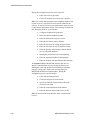
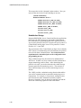
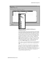
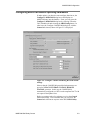
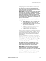
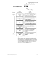
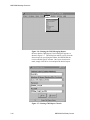
As you can see from Figure 1-6, there are many MODCOM
operational and object parameters that must be configured for
the Central Station, MODCOM and premise operation. As
previously stated it is critical to identify and specify your project
parameters prior to the configuration and programming process.
Remember that an ounce of planning is worth a pound of
rework.
3-MODCOM
Logical Configuration
Central
Station
Phone
Numbers
Primary
Secondary
Central
Station
Central
Station
Receiver
Labels
Program
Controlled
Operations
Rec # 1
Rec # 2
Premises
Account
Labels
Configuration
Controlled
Links
Acc # 1
Acc # 2
through
through
Rec # 80
Acc # 255
For Security Applications
Partitions (secured areas)
within premises accounts
must also be configured.
Premises
For Security / Access Control
Applications Buildings,
Partitions (secured areas)
and doors within premises
accounts must also be
configured.
Figure 1-6: 3-MODCOM Logical Configuration.
This description is simply an overview of the aspects of
configuring and programming the MODCOM. Detailed
applications related methods are described in latter modules of
this self-study.
As a new MODCOM user it is important that you understand the
onboard HELP Utility in your 3-SDU, version 3.0 or greater.
This is a valuable, labor saving tool when used dynamically
during your project development process. This HELP Utility
not only provides definitions of MODCOM features and
functions, it also provides sample rules, which may be copied
into the rules editor for your application, and edited to meet
your project requirements. This HELP Utility also contains
template files of the various Central Station protocol codes used
for Central Station event reporting.
Note: We recommend that you take a few minutes to tour the
HELP Utility to become familiar with this valuable resource.
The examples in this self-study will teach you to use SDU’s help
during the MODCOM configuration and programming process.
MODCOM Self-Study Course
1.21
3-MODCOM Product Description
To better understand developing applications which employ the
MODCOM and applications which integrate Access Control and
Security into the EST3 Life Safety System you need to
understand the features and functions that have been added to
version 3.0 of the 3-SDU. A description of what’s new in the
SDU follows.
The Command List
During MODCOM, Access Control and Security applications it
may be desired to branch to a sub-routine when an event occurs.
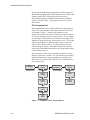
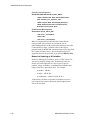
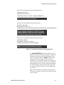
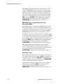
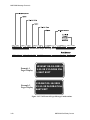
For example, Figure 1-7 shows a flow diagram of a rule
sequence on an event’s activation. For the sake of this example,
let’s assume that the event was a security alarm. In our example,
we are using a Central Station service and the first output action
might be to report this security alarm to this service. The second
output action might be to annunciate this security event at the
security office on the premises. The third output action may
send a message to a pager. The fourth output action may be to
report to the Central Station when the security intrusion has been
verified on the premises.
In our example, we also want to sound an on-premises security
alarm for a period of 3 minutes. We will due this by activating a
subroutine from the last output command of our primary rule,
which turns on a security bell, delays for 180 seconds and turns
the security bell off.
EVENT
ACTIVATION
OUTPUT
ACTION
SUB-ROUTINE
ACTIVATION
OUTPUT
ACTION
OUTPUT
ACTION
DELAY
OUTPUT
ACTION
OUTPUT
ACTION
OUTPUT
ACTION
BRANCH
ON
EVENT
Figure 1-7: Example Security Alarm Sequence.
1.22
MODCOM Self-Study Course
3-MODCOM Product Description
This rule subroutine is executed on activation of an object in the
SDU database called a Command List. A Command List is an
EST3 object you create during the configuration process. Each
Command List object you create requires a unique label like any
other SDU database object.
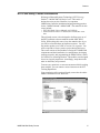
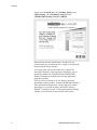
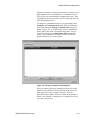
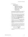
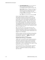
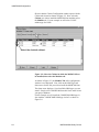
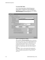
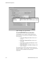
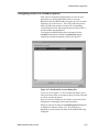
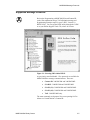
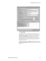
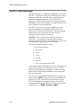
To configure a Command List object you would simply select
Configure and Command List from the SDU main menu bar.
This would display the Manage Command Lists dialog box
shown in Figure 1-8. You then simply insert a Command List
object, label it and create a meaningful description. For our
example we will create a sound security bell command list
object. This command list will then be used to activate the
premise alarm bell on a security alarm.
Figure 1-8: Manage Command Lists Dialog Box.
It may be simpler to think of Command List objects as events,
which activate within the EST3 application but do not fit into
other input device types or input event types. Such as, a
Security Perimeter Alarm. In this case, the Security Perimeter
Alarm is an event that is configured as a Command List device
type with a unique label.
MODCOM Self-Study Course
1.23
3-MODCOM Product Description
In this way, a command list, when activated, executes a
subroutine rule, as a normal rule, on activation of the predefined
system event. Where the input event type would be
ACTIVATION, the device type would be COMMANDLIST
and Command List label is what you’ve assigned during the
configuration process.
Assuming that we are reporting on a general alarm basis to the
Central Station and using Contact ID protocol, the rules for our
Figure 1-7 example may look like:
[Security Alarm Sequence]
SECURITYALARM PARTITION ‘FLOOR1_WEST’:
SEND ‘XYZAcct1234’ MSG “ActivateEventCode”,
FAST ‘SecDesk_Flr1_Perimiter_LED’,
SEND ‘PageCo’ MSG “UserID$(CR)$Message”,
SEND ‘XYZAcct1234’ MSG “VerifyEventCode”,
ACTIVATE ‘Sound_Alarm_Bell’;
[Sound Alarm Bell Sequence]
ACTIVATION ‘Sound_Alarm_Bell’:
ON ‘Floor*_SecurityBell’,
Delay 180,
OFF ‘Floor*_SecurityBell’;
As you can see, the integration of MODCOM, Access Control
and Security into EST3 applications has created new Input
Events and Output Commands.
ACTIVATION – An Input Event that lets you detect a
predefined Command List activation.
ACTIVATE – An Output Command that lets you
activate a command list from a rule and subsequently
execute a subroutine rule.
RESTORE – An Output Command that lets you restore
a command list from a rule.
SEND – An output Command that lets you send a
message (predefined code) to a Central Station through
the MODCOM when an event occurs.
Command Lists are used in advanced Access Control and
Security applications. As previously stated, these integrated
system applications are beyond the scope of this self-study
course and are covered in the EST3 Synergy Enabled®
Certification Course.
1.24
MODCOM Self-Study Course
3-MODCOM Product Description
The Command Qualifiers
On the surface the rules of the previous example look like they
will do the trick. However on closer examination we see that
this is not the case.
From your previous experience with writing rules you should
understand the rules activate sequentially (top-down) and restore
sequentially (bottom-up). With this knowledge it is easy to see
that the primary rule reports to the Central Station on the rule
activation and restoration, fast flashes the LED on activation and
turns off the LED on restoration. The Command List also
executes on the primary rules activation and restores during the
primary rules restoration, sounding the security bells for a
second 3-minute sequence.
In our example, we want to report the security alarm to the
Central Station and Pager Service during the rule’s activation
sequence, report the security intrusion verification during rule’s
restoration sequence and sound the security alarm bells once
only during rule’s activation sequence. To accomplish this new
behavior for rules, command qualifiers have been added to the
syntax of rules.
A command qualifier is simply a + or – added to the command
of a rules output statement. A + causes the command to execute
only on a rule’s activation. The – causes the command to
execute only on a rule’s restoration. As shown below, by adding
the appropriate command qualifiers to our example rules we can
control when we want the commanded actions to occur.
[Security Alarm Sequence]
SECURITYALARM PARTITION ‘FLOOR1_WEST’:
+SEND ‘XYZAcct1234’ MSG “ActivateEventCode”,
FAST ‘SecDesk_Flr1_Perimiter_LED’,
+SEND ‘PageCo’ MSG “UserID$(CR)$Message”,
-SEND ‘XYZAcct1234’ MSG “VerifyEventCode”,
+ACTIVATE ‘Sound_Alarm_Bell’;
[Sound Alarm Bell Sequence]
ACTIVATION ‘Sound_Alarm_Bell’:
ON ‘Floor*_SecurityBell’,
Delay 180,
OFF ‘Floor*_SecurityBell’;
These rules now report to the Central Station at the appropriate
time and sound the security alarm bell once. These rules could
have been written as follows and still sounded the security alarm
bells once.
MODCOM Self-Study Course
1.25
3-MODCOM Product Description
[Security Alarm Sequence]
SECURITYALARM PARTITION ‘FLOOR1_WEST’:
+SEND ‘XYZAcct1234’ MSG “ActivateEventCode”,
FAST ‘SecDesk_Flr1_Perimiter_LED’,
+SEND ‘PageCo’ MSG “UserID$(CR)$Message”,
-SEND ‘XYZAcct1234’ MSG “VerifyEventCode”,
ACTIVATE ‘Sound_Alarm_Bell’;
[Sound Alarm Bell Sequence]
ACTIVATION ‘Sound_Alarm_Bell’:
+ON ‘Floor*_SecurityBell’,
+Delay 180,
+OFF ‘Floor*_SecurityBell’;
Note: It’s important to note here that the Central Station
messages used in this example are created for ease of
understanding and are not the actual coded messages sent to the
Central Station or Pager. Detailed codes for the various
protocols used for MODCOM communications will be described
later in this self-study course. Detailed templates for EST3
supported protocols are provided in you onboard HELP Utility.
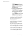
Numerical Indexing or N-Variables
Numerical Indexing (N-Variables), prior to 3-SDU release 3.0,
was used to simplify writing rules. A numerical index was
always used in the input side of a rule to specify specific
numbers, ranges of numbers or combinations of numbers and
ranges in the rule’s input object label. For example:
A number - <N:#>
A range - <N:#-#>
A combination - <N:#,#-#,#,#-#>
A Numerical Calculator or Operator could then be used in a
rule’s output object label to determine which output objects
were to be activated.
1.26
MODCOM Self-Study Course
3-MODCOM Product Description
For example the rule:
[Alarm Notification]
ALARM ‘FLOOR<N:1-9>*’:
AMPON ‘Floor<N>_AMP’ TO ‘EVAC’,
AMPON ‘Floor<N+1>_AMP’ TO ‘EVAC’,
AMPON ‘Floor<N-1>_AMP’ TO ‘EVAC’,
AMPON ‘Floor*_AMP’ TO ‘ALERT’,
ON ‘Floor<N>_STB’,
ON ‘Floor<N+1>_STB’,
ON ‘Floor<N-1>_STB’;
broadcasts default EVAC messages to the floor of incident, floor
above and floor below and turns on the strobes to the same
floors. A default ALERT message is broadcast to all other
floors.
Prior to release 3.0, the numerical index would not recognize a
leading 0. For example, if the previous rule was for a 25-story
building where the floors were labeled Floor01 through Floor25,
you could not use the label ‘Floor<N:01-25>*’ in the
input statement. This rule would not include any object for
floors 01 through 09. Prior to release 3.0 you would have
written two rules, one labeled ‘Floor0<N:1-9>*’ and the
other labeled ‘Floor<N:10-25>’.
CAUTION: You can write the label ‘Floor*<N:1-25>*’
and make it work. However, the * prior to the numerical index
will include all variable modifiers between Floor and the
<N:1-25>. Which may include undesired input objects in
the rule. The bottom line is to take caution when using a
wildcard (*).
3-SDU release 3.0 or greater provides an additional function to
the numerical index and numerical calculator or pperator used in
the input and output object labels. Now you can specify the
minimum number of digits or width to be used in the numerical
index within the rule. The syntax would be:
Input Object Label: <N:#-#:W>
Output Object Label: <N:W>
where W is the minimum number of digits or width of the index.
The default is 1.
MODCOM Self-Study Course
1.27
3-MODCOM Product Description
This accepts the 0 of the 1 through 9 index numbers. Now you
can write the rule for the 25-story building in one rule:
[Alarm Notification]
ALARM ‘FLOOR<N:1-25:2>*’:
AMPON ‘Floor<N:2>_AMP’ TO ‘EVAC’,
AMPON ‘Floor<N+1:2>_AMP’ TO ‘EVAC’,
AMPON ‘Floor<N-1:2>_AMP’ TO ‘EVAC’,
AMPON ‘Floor*_AMP’ TO ‘ALERT’,
ON ‘Floor<N:2>_STB’,
ON ‘Floor<N+1:2>_STB’,
ON ‘Floor<N-1:2>_STB’;
Substitution Strings
Integrated MODCOM, Access Control and Security applications
that require the EST3 System to report to the Central Station
have created new requirements for the EST3 applications tools.
As previously discussed, the EST3 System can report events to a
Central Station and/or pager in one of five protocols: Contact
ID, SIA, 4/2, 3/1 and TAP.
The requirements of the Central Station or Pager Service that the
EST3 system is communicating with will determine the protocol
to be used for these communications. It is critical that these
requirements be determined prior to the configuration and
programming process.
These coded messages may be numerical or alphanumerical
ASCII text. In either case, they contain relevant information to
support monitoring premises status. After determining the
protocol to be used, you need to determine the coded message
content required by the monitoring service. The structure of
these coded messages varies from one monitoring service to
another.
The 3-SDU provides a substitution string function that enables
you to tailor communications to match the monitoring service
requirements. For example, in all protocols, sending account,
user ID and event codes information would be required.
However, frequently it may be desired to send the time and the
date of the event being reported or other information.
1.28
MODCOM Self-Study Course
3-MODCOM Product Description
The syntax for a Substitution String is:
$(Alphanumeric ASCII Field)
where the dollar sign $ indicates that a substitution string
follows. The actual substitution message data is enclosed in the
parenthesis (( )).
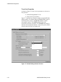
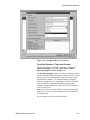
Figure 1-9 shows examples of using a Substitution String in a
rule. In the SIA DCS protocol example, if any of the smokes on
Floors 1 through 7 go into alarm, you send the fire alarm event
(FA<N>) for the specific floor to the for the specified account
to the Central Station’s specified receiver. By using the
substitution string function, you also send the date and time of
the event.
It is important to note here that the available Substitution Strings
for the SIA DCS protocol are:
·
$(TIME) inserts the default 24-hour clock time.
·
$(DATE) inserts the default MMDDYY date
format.
·
$(USER) inserts the user identification code.
Note: As shown in Figure 1-9, the substitution strings
must be entered into the message before the event
(FA<N> in our example).
·
$(USERID) inserts the user identification code
and a qualifier (i.e. pin number for individual
identification). USER ID differs from USER in that
it sends a lower case id with the pin number.
Note: USER and USER ID numbers are configured in
the Access Control Database software used for EST3
Synergy Enabled® Access Control applications. These
would be pin numbers of individuals approved for entry
into a protected premise. For example, if you wanted to
report the individual pin number access was granted for
you would use an access granted event type (DG) and
the User ID substitution string:
“DG$(USERID)”
SIA DCS substitution conventions are described in detail in
Module 3 of this self-study.
MODCOM Self-Study Course
1.29
3-MODCOM Product Description
In the TAP protocol example, if any of the smokes on Floors 1
through 7 go into alarm, you send the pager ID and fire alarm
event to the specified pager via the pager service. Again, by
using the Substitution String you also send the carriage return
$(CR) which separates the pager ID and message, the date,
time and specific location of the event $(LOCATION:M-N).
It is important to note here that the available Substitution strings
for the TAP protocol are:
·
$(TIME) inserts the default 24-hour clock time.
·
$(TIME12) inserts the 12-hour clock time.
·
$(TIME24) inserts the 24-hour clock time.
·
$(DATE) inserts the default MM-DD-YY date
format.
·
$(MMDDYY) inserts the MM-DD-YY date
format.
·
$(MMDDYYYY) inserts the MM-DD-YYYY
date format.
·
$(DDMMYYYY) inserts the DD-MM-YYYY
date format.
·
$(USER) inserts the user identification code.
·
$(CR) inserts a carriage return used to separate the
User ID and the event message.
·
$(“) inserts a quotation mark.
·
$(LOCATION) inserts the location text from the
corresponding objects 42-character message field.
Note: Remember that the maximum number or
characters that can be included into a TAP message,
including the User ID and other Substitution Strings, is
59.
1.30
MODCOM Self-Study Course
3-MODCOM Product Description
{Example of rule using Substitution String with SIA DCS protocol}
[Send Floor Fire Alarm]
Alarm Smoke ‘Floor<N:1-7>*’ :
+SEND ‘SIA_Account_1234’ MSG “$(DATE)$(TIME)FA<N>”;
{Where the available Substitution Strings for the SIA DCS protocol are
$(DATE), $(TIME), $(USER) and $(USERID).}
{Example of rule using Substitution String with TAP protocol}
[Send Floor Fire Alarm]
Alarm Smoke ‘Floor<N:1-7>*’ :
+SEND ‘PagerInc’ MSG “ID53244$(CR)$(DATE) $(TIME) FireAlarm $(LOCATION:M-N)”;
{Where the available Substitution Strings for the TAP protocol are
$(DATE), $(MMDDYY), $(MMDDYYYY), $(DDMMYYYY), $(TIME),
$(TIME12), $(TIME24), $(USER), $(”), $(CR), $(LOCATION)
and $(LOCATION:M_N). M-N specifies which of the characters
in the points 42 character message are to be included.}
{Example of rule using Substitution String with Contact ID protocol}
[Send Security Alarm]
SecurityAlarm ‘Partition<N:1-15:2>*’ :
+SEND ‘Account1234’ MSG “1130<H>$(USER)”;
{Where the only Substitution String for the ContactID protocol is
$(USER) . This is rarely used. Remember that only numerical
hexadecimal coded messages may be sent to the Central Station.}
Figure 1-9: Example Substitution String Applications.
The $(LOCATION) Substitution String inserts the
number of characters starting at character 1 from the 42character object message into the 59-character field
which is available in the rule’s MSG. In that, if after
entering User ID, date and time only 30 of the 59
characters are still available, only the first 30 characters
of the object message will be inserted. It is important to
understand that you will need to predetermine and plan
the actual message content to be sent to the pager and
the object message text so that no relevant information
is excluded.
Note: Also remember to use spaces in the message, as
shown in our example, to be sent to the pager to promote
ease of reading.
MODCOM Self-Study Course
1.31
3-MODCOM Product Description
·
$(LOCATION:M-N) inserts the location text
from a specified range of characters from
corresponding objects 42-character message field.
Where: M specifies the 1st character of a range of
characters from the 42-character object message
field to be that is to be included in the event
message and N is the last character of the range to
be included in the event message.
Note: M must be greater than 0 and less than N.
For the Contact ID protocol example, it is important to
understand that a hexadecimal coded message is sent to the
Central Station, which may specify the event, partition and
device number. Rarely is the substitution string used to send
addition information. In this example, each of the floors has
been configured into a partition. If any of the security alarm
devices within a partition in our example goes into alarm, you
send a event qualifier 1 for activation and the security alarm
event 130<H> specifying the partition to the specified Central
Station account (receiver). In this case the substitution string is
used to also send the user ID.
Note: Remember that in Contact ID hexadecimal coded
messages are sent to the Central Station. You need to verify
with the Central Station provider the code requirements of your
application. Sending information that the Central Station is not
equipped to use is meaningless.
In all three example cases, the Central Station account or Pager
account destination is specified by its label after the SEND
command and is enclosed in ‘ ‘. MSG specifies that the
message follows, which in enclosed in “ “.
Hexadecimal Indexing or H-Variables
3-SDU release 3.0 or greater also offers hexadecimal indexing
(H-Variables), which operate similar to numerical indexing.
This feature enables you to incorporate base16 hexadecimal
numbers into your labels or coded messages to be sent to the
Central Station. This is a critical feature when using the Contact
ID protocol to report to a Central Station.
Like the numerical index, a hexadecimal index is used in the
input side of a rule to specify specific numbers, ranges of
numbers or combinations of numbers and ranges in the rules
input object label.
1.32
MODCOM Self-Study Course
3-MODCOM Product Description
For example:
A number: <H:#16>
A range: <H:#16-#16>
A combination: <H:#16,#16-#16,#16,#16-#16>
A hexadecimal calculator or operator can be used in a rules
output object label to determine which output objects are
activated. Also like numerical indexing you can specify the
minimum number of digits (W) within the hexadecimal index:
<H:#16-#16:W>
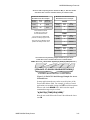
Before we continue, let take a few minutes to review
hexadecimal conventions. First its important to note that
hexadecimal is a base-16 numbering system. Each hexadecimal
digit has a decimal equivalent. Figure 1-10 shows the
conventional hexadecimal integers or digits and their decimal
equivalents.
Conventional
Hexadecimal vs Decimal
Correlation
Hexadecimal
Digit
Decimal
Equivalent
0
1
2
3
4
5
6
7
8
9
A
B
C
D
E
F
0
1
2
3
4
5
6
7
8
9
10
11
12
13
14
15
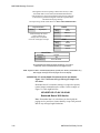
Figure 1-10: Conventional Hexadecimal Conventions.
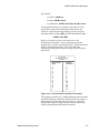
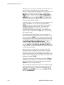
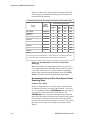
The telephone providers use a modified hexadecimal convention
for data transmission, which the Central Station must comply to
when using the Contact ID protocol. Figure 1-11 shows the
Hexadecimal integers or digits and their decimal equivalents
used for the modified hexadecimal conventions.
MODCOM Self-Study Course
1.33
3-MODCOM Product Description
Modified
Hexadecimal vs Decimal
Correlation
Hexadecimal
Digit
Decimal
Equivalent
0
1
2
3
4
5
6
7
8
9
B(*)
C(#)
D
E
F
10
1
2
3
4
5
6
7
8
9
11
12
13
14
15
Figure 1-11: Modified Hexadecimal Conventions for
MODCOM applications.
Note: Observe that there is no hexadecimal A. You need to
observe these variations when using the H-variables. In that,
sending a 01 or A1 is received as a 01 at the Central Station. If
you were not careful, two input points having hexadecimal ID’s
of 01 and A1, respectively, would send only 01 to the Central
Station. This could create some confusion to the Central Station
provider.
You can mix N-Variables and H-Variables within a rule. This
feature enables you to automatically convert from decimal to
hexadecimal or from hexadecimal to decimal. For example the
following rule:
[Send Point ID Smoke Alarms]
Alarm Smoke ‘L1_SMK<N:1-15:2>’:
+SEND ‘Central’ MSG “FA<H>”;
sends a fire alarm event message to the Central Station which
includes a hexadecimal code to identify the specific smoke
detector on level 1 that went into alarm.
1.34
MODCOM Self-Study Course
3-MODCOM Product Description
CAUTION: This conversion utilizes Modified Hexadecimal
digits. In that a conventional hexadecimal A is converted to a 0.
You’ll need to take this into account when labeling objects,
creating messages and writing rules. A good labeling plan
would be a helpful tool is determining the modified hexadecimal
values required for the Central Station.
The following rule is an example of converting from
hexadecimal to decimal. In this example, the Central Station
transmits a confirmation of the receipt of a closing message from
a specific floor identified by a hexadecimal number. These
confirmations are events which are configured as CLOSE_1
through CLOSE_C Command Lists. As each confirmation
occurs it is to light a corresponding LED steady on the premises,
which has a decimal labeling convention.
[Confirm Floor Closings]
Activation ‘CLOSE_<H:1-C>’ :
STEADY ‘FLOOR_CLOSED_LED<N:2>’;
Where Floor 1 lights LED 1 to Floor C lights LED 12.
Again, remember that the hexadecimal digits in our example are
conventional, not the modified version required by MODCOM
applications.
MODCOM Self-Study Course
1.35
3-MODCOM Product Description
MODCOM Installation Considerations
Telephone Line Requirements
Prior to installing the 3-MODCOM or 3-MODCOMP you need
to arrange for suitable TELCO lines and services. These
MODCOM dialers can be used in most telephone line
applications. The 3-MODCOM and 3-MODCOMP should not
be used in applications where:
·
The Central Station telephone number(s) cannot be
dialed directly and require operator assistance on the
call.
·
Multiparty or party-line service exists.
·
Operator assistance is required to complete a call
where a foreign exchange (FX) connection cannot
be introduced.
·
A connection cannot be established within 38
seconds following the completion of dialing.
·
An nonsupervised WATS or ground-start
connection is used.
These MODCOM dialers are compatible with any switched
direct dialing (local) or direct distance dialing (DDD) telephone
network that does not require operator assistance.
The 3-MODCOM and 3-MODCOMP dialers prevent jamming
by incoming calls when used with the Called Party Disconnect
telephone service option. In areas where Called Party
Disconnect is not available and jamming is a problem, a
separate, confidential, unlisted telephone number should be used
for the MODCOM. Two unlisted telephone numbers, one for
each MODCOM telephone line, provide maximum dialer
integrity.
The 3-MODCOM and 3-MODCOMP must be connected to the
incoming telephone line ahead of any other equipment (e.g.,
telephones, answering machines, FAX machines) connected to
the phone line and immediately after the demarcation block.
This requirement ensures that the MODCOM dialer circuit can
seize the line during an alarm, disconnecting the other
equipment on the telephone line.
Other requirements:
1. Do not use a telephone line that is considered
essential for conducting the customers business.
When possible use a separate, dedicated line for
MODCOM use.
1.36
MODCOM Self-Study Course
3-MODCOM Product Description
2. When the input telephone line is composed of rotary
telephones, use the telephone line with the highest
telephone number for MODCOM connection to
create the least interference with the customers
business telephone lines.
3. When the MODCOM connection is made to a
TELCO (telephone) line also used for business,
advise the customer that telephone service will be
disrupted for a few minutes during the MODCOM
dialer connection periods.
4. In areas where connection must be made to the
telephone provider’s own connector blocks, they
should be wired per the USOC RJ-31X or RJ-38X
configuration specified on the MODCOM
installation sheet (P/N 387476).
5. When the MODCOM is configured as a two-line
dialer the two incoming telephone lines must be
used and connections must be made to each line.
Installing the MODCOM module
Prior to installing the 3-MODCOM or 3-MODCOMP into the
EST3 chassis:
·
Review your project requirements and source
information for MODCOM parameters and the
proper location where the MODCOM is to be
installed on the EST3 chassis rail.
·
Arrange for suitable TELCO lines and services per
the line requirements given above.
·
Make sure the power is OFF on the cabinet where
the MODCOM is to be installed.
To install the MODCOM module:
1. Use an anti-static wrist strap or equivalent to ground
yourself while handling the MODCOM during
installation.
2. Carefully remove the MODCOM module from the
anti-static bag or box that the module is packed in.
This module is shipped with a blank door cover
installed. Always handle this module by its edges or
by this door.
MODCOM Self-Study Course
1.37
3-MODCOM Product Description
Note: Do not discard the anti-static carrier and shipping
materials you received with the module. If a failure or
damage occurs, the module must be shipped back to the
factory in the anti-static packaging.
3. Place the anti-static bag on a flat surface and place
the module, with the modular phone jacks facing the
top, on this bag. Inspect the module for visible
shipping damage, turn it over and inspect the other
side for visible damage.
4. If a Control/LED display operator layer module is to
be installed, remove the blank front plate and
assemble the Control/LED module membrane to it
per installation sheet P/N 270493. Attach the
Control/LED display module to the MODCOM via
the plastic standoffs and the ribbon cable provided.
5. Carefully plug the MODCOM module into the
predetermined rail position within the host cabinet.
CAUTION: Ensure that the module aligns with the
plastic guide pins and seats firmly onto the rail
connectors. These modules mount fairly easily onto the
rail. If you find that you have to force the module into
place you are probably doing it wrong. In this case,
inspect the rail connectors for bent pins and reinstall the
module carefully.
6. After you have ensured that the module is mounted
properly, fasten the module in place with its plastic
pushpins.
Note: A special removal tool is provided with the
cabinet that enables you to unsnap these pushpins when
it is desired to remove any module from its host chassis.
7. Restore power to the cabinet.
This completes the physical installation of the MODCOM
modules. You are now ready to connect the MODCOM to the
facility TELCO telephone lines, download its configuration and
programming data, and test transmissions to the monitoring
service.
1.38
MODCOM Self-Study Course
3-MODCOM Product Description
Connecting the MODCOM to the TELCO lines
Plug one end of the supplied 8-position modular telephone
cable(s) to the appropriate TELCO line jack(s) on the top of the
MODCOM module.
DO NOT plug the other end of the cable(s) into the RJ-31X
jack(s) until you have downloaded the MODCOM applications
and are ready to test the system. This prevents interference with
other normal customer traffic and equipment until you are ready
for the final connection and testing phase.
When you are ready for the final connection and testing phase
connect the TELCO line jack(s) as follows:
J20 – Line 1 Jack
J21 – Line 2 Jack
Single-line dialer
Second line for two-line dialer
(or first line for two-line dialer)
Incoming Modem Line
Note: NFPA 72 Fire Alarm System compliance requires that the
MODCOM be connected to two loop-start telephone lines.
When the s uses ground-start telephone lines, two loop-start
lines must be installed for the dialer.
To determine the type of TELCO lines that are present on
premises:
1. Disconnect the phone line pair.
2. Connect the line pair to a test meter.
3. The meter will read between 48 to 52 Vdc between
the lines if it is equipped for loop-start.
4. The meter will read 0 Vdc between the lines, 48 to
52 Vdc between one line and ground and 0 Vdc
between the other line and ground if it is equipped
for ground-start.
Note: NFPA 72 Certified Fire Alarm System and Burglar Alarm
System compliance requires that the TELCO telephone line be
Called Party Disconnect or Timed-Released Disconnect, which
permit the MODCOM to seize the line when the TELCO line is
in use.
To determine that the line is Called Party Disconnect have
someone call the s from outside, hang up the premises telephone
but not the outside telephone, wait 40 seconds and then pick up
the premises telephone again. If the caller is still connected the
system does not have Called Party Disconnect service.
MODCOM Self-Study Course
1.39
3-MODCOM Product Description
Module 1 evaluation
This concludes Module 1 of the 3-MODCOM Self-Study Course.
Return to the objectives stated at the beginning of this module.
Study them carefully to ensure that you are comfortable with
each objective. If not, return to that section and review it. When
you are satisfied, proceed to Module 2. You will be tested at the
end of this self-study course.
1.40
MODCOM Self-Study Course
Module 2
Configuring the MODCOM
Summary
This self-study module introduces you to the procedures you
must employ to configure the 3-MODCOM and 3-MODCOMP
into an EST3 3-SDU application. This module defines and
describes each MODCOM property or parameter that must be
configured.
Content
Introduction to module 2 • 2.2
Key items • 2.3
Objectives • 2.4
Entering the MODCOM into a project • 2.5
Configuring MODCOM General Operating Parameters• 2.9
To set the DACT Settings • 2.10
To set the Public Service Telephone Network Settings • 2.11
To set Line Properties • 2.12
To set the Dial In Phone Number • 2.13
To set MODCOM Timers and Counters • 2.14
Configuring MODCOM Receiver Properties • 2.16
Insertin a MODCOM Receiver • 2.17
Creating a Receievr Label and Description • 2.17
Congiguring Receiver Phone Numbers and Protocol • 2.19
To set the Receiver's Timer and Counter • 2.21
To set the Receiver Default Messages • 2.22
Configuring MODCOM Account Properties • 2.25
Creating an Account Label and Description • 2.26
Selecting the Receiver, its Protocol and entering the Central
Station Account Number • 2.27
Setting the Dial Test Timer Parameters • 2.29
Module 2 evaluation • 2.31
MODCOM Self-Study Course
2.1
3-MODCOM Configuration
Introduction to module 2
This module covers the procedures required to configure both
the 3-MODCOM and 3-MODCOMP into the 3-SDU database.
This self-study module provides detailed instruction on entering
the MODCOM into the database, selected its operational
properties or parameters and setting the MODCOM timers and
counters to meet the needs of your specific application.
Also covered are the procedures for configuring Central Station
receiver and premises account properties. Details on
transmission protocols for dialer application are covered in
Module 3 of this self-study course. Descriptions on
programming the many MODCOM applications are covered
later in this course.
Configuring the MODCOM is an easy task of simply selecting
the desired properties from SDU dialog boxes. The MODCOM
has a default setup for NFPA 72 compliance built into the SDU
software. These default settings will handle a majority of
MODCOM applications.
This self-study will focus on basic fire only applications using
the Contact ID protocol, which is the prevalent fire application,
the MODCOM is used in. Although discussed in this course, the
more sophisticated Security, Access Control and Keypad display
MODCOM applications are covered in the factory-based EST3
Synergy Enabled® training Course.
Review the Configure Projects, Cabinets, LRMs, and MODCOM
topics in your 3-SDU, Version 3.0 HELP Utility. You can get
to the HELP utility through the 3-SDU or from your Online
Support Tools CD, release 4.0 or later.
Prior to starting this module and the remainder of this self-study
course, install or upgrade the 3-SDU to version 3.0 or greater. It
is recommended that you create a practice project that you can
develop during these lessons. As each step of the MODCOM
configuration and programming process is covered, you can
practice what you have learned in your practice project. Having
your project open during this lesson will make the HELP utility
readily available for you reference.
Associated study
Use the following technical reference manuals as associated
study material for this module:
•
•
2.2
EST3 Installation and Service Manual, P/N 270380, Rev 4.0 or
later)
Modem Communicator 3-MODCOM/3-MODCOMP Installation
Sheet, (P/N 387476)
MODCOM Self-Study Course
3-MODCOM Configuration
Key items
Key points to look for:
•
•
•
•
•
•
•
•
NFPA 72 Central Station, Remote Station compliance Mode
Fully Programmable Mode
Configuring MODCOM phone lines and supervision
Configuring MODCOM Counter and Timer properties
Available communications protocols
Configuring Central Station Receiver properties
Configuring premise Account properties
Default message types
Key terms and operations to learn:
•
•
•
•
•
•
•
•
•
•
•
•
MODCOM Self-Study Course
Override Answering Machine
Default Dialing Methods
Ring Cycle Types
Calling Party Disconnect
Ring Cycle Count
Line Cut Monitoring
Tone vs. Pulse dialing
Contact ID protocol
SIA DCS, 3/1 and 4/2 protocols
TAP protocol
CMS Account numbers
Dial Test Timer settings
2.3
3-MODCOM Configuration
Objectives
Upon completion of this module you will be able to:
1. Configure the 3-MODCOM or 3-MODCOMP for the default
NFPA 72 compliant or fully programmable operational
mode based on the requirements of your project.
2. Describe the relationship of Central Station Receivers and
Premises Accounts within the MODCOM configuration
process.
3. Create meaningful Receiver and Account labels and
descriptions.
4. Configure Central Station Receiver properties.
5. Configure Premise Account properties.
6. Describe the purpose and ranges for the various MODCOM
Counters and Timers.
2.4
MODCOM Self-Study Course
3-MODCOM Configuration
Entering the MODCOM into a project
Review the Configure Projects, Cabinets, LRMs and MODCOM
topics in your 3-SDU, Version 3.0 HELP Utility. You can get
to the HELP utility via the 3-SDU or from your Online Support
Tools CD, release 4.0 or later.
Prior to starting this module and the remainder of this self-study
course, install or upgrade the 3-SDU to version 3.0 or greater. It
is recommended that you create a practice project that you can
develop during these lessons. As each step of the MODCOM
configuration process is covered, you can practice what you have
learned in your practice project. Having your project open
during this lesson will make the HELP utility readily available
for you reference.
Entering the 3-MODCOM and 3-MODCOMP into your project
database is an easy step-by-step process. After you have created
a new project, configured the project parameters and configured
each cabinet in your project, you simply enter the MODCOM
into the required slot of the cabinet in which it is to reside. A
description of these steps follows.
To enter the MODCOM into your project, select Configure from
the main menu and Cabinet from the drop-down menu as shown
in Figure 2-1.
Figure 2-1: Select Configure and Cabinets.
MODCOM Self-Study Course
2.5
3-MODCOM Configuration
Observe that the Cabinet Configuration window opens with the
Cabinet tab selected as shown in Figure 2-2. Now select the
Cabinet you wish to install the MODCOM into and then select
the Modules tab. For our example we will select 3-CAB7
cabinet type for CAB2.
Select the desired cabinet.
Figure 2-2: Select the Cabinet in which the MODCOM is to
be installed, then select the Modules tab.
As shown in Figure 2-3, the Modules Tab of the configuration
window is now displayed. Now click on the LRM Type and
down-arrow for the slot you wish to install the MODCOM into.
The down-arrow displays a list of available LRM types you can
install. Simply select 3-MODCOM from this list to install it into
your project database.
For this example we will install the 3-MODCOM LRM type in
slot 4 and the 3-MODCOMP LRM type in slot 5 as shown in
Figure 2-4.
2.6
MODCOM Self-Study Course
3-MODCOM Configuration
Figure 2-3: Select the 3-MODCOM LRM type for
installation into slot 4.
You should remember from your past experience with the SDU
that you have the ability to preset the SDU’s behavior. If when
you initially setup the SDU behavior in the Options function of
the main menu you selected to automatically display the LRM
Configuration dialog boxes when you enter each LRM into the
database, you would have seen the Configure 3-MODCOM
dialog box during your practice. If this is the case, click on the
OK button for this display for this example. For this lesson we
will manually select the Configure 3-MODCOM function by
pressing the LRM Config button on the Modules Tab.
After we have entered the 3-MODCOM and 3-MODCOMP into
slots 4 and 5 respectively we need to create a unique label for
each.
The content of these labels is important to you as the system
developer. You will view these labels in your LRM Limitation
Filter during the object configuration process and they also
appear on various reports. You should remember from your past
EST3 training, that a label should include a combination of
Location, Function and Device Type.
MODCOM Self-Study Course
2.7
3-MODCOM Configuration
In our example of Figure 2-4, Cab2 is the location within our 3node system. In multi-area, multi-MODCOM facilities, you may
want to include building, floor or other label modifiers to be
more specific.
The example labeling of Figure 2-4 shows that the second label
modifier gives the function of each MODCOM type. This would
be especially important to you in multi-MODCOM applications.
In our example, the 3-MODCOM is used for Central Monitoring
Station reporting (labeled CMS), while the 3-MODCOMP is
used to send event messages to a pager (labeled Pager).
The function label modifier can be important. For example, in
MODCOM failover applications, where a backup MODCOM is
used, you may want to specify which MODCOM is primary and
which is the backup. In applications where excessive Access
Control and Keypad Display traffic requires that you dedicate a
MODCOM for the Access Control and Keypad Display
communications and a separate MODCOM for Central Station
reporting, you may want to specify which MODCOM provides
modem communications and which provides the dialer
communications. The last modifier in our example for both
MODCOMs indicates the device type (labeled Modcom).
Figure 2-4: 3-MODCOM and 3-MODCOMP with labels.
After you have practiced entering the MODCOM into your
project you are now ready to configure the operating parameters,
receivers, and accounts for each MODCOM type.
2.8
MODCOM Self-Study Course
3-MODCOM Configuration
Configuring MODCOM General Operating Parameters
If under options, you have the auto-configure function set, the
Configure 3-MODCOM dialog box would display on
MODCOM entry into the database. If not, you can get to the
Configure 3-MODCOM dialog box by selecting it from the
Cab2, Modules tab and selecting the LRM Config button. In
either case, the Configure 3-MODCOM dialog box, with the
General tab selected, shown in Figure 2-5 is displayed.
Figure 2-5: Configure 3-MODCOM Dialog Box with default
settings.
Observe that the 3-MODCOM general default parameters are
preset for NFPA 72 CENTRAL STATION, REMOTE
STATION operation. In this way the 3-MODCOM is
automatically configured as a NFPA code-compliant DACT with
two supervised telephone lines.
Before we continue take a few minutes to review the General
tab default settings. Also remember that you can review the
General tab selections at any time in the SDU HELP Utility.
MODCOM Self-Study Course
2.9
3-MODCOM Configuration
To set the DACT Mode
As previously stated the general 3-MODCOM parameters
default to NFPA 72 CENTRAL STATION, REMOTE
STATION DACT compliance. To make your 3-MODCOM
fully programmable click on the down-arrow and select FULLY
PROGRAMMABLE as shown in Figure 2-6.
Figure 2-6: Selecting DACT settings.
When the FULLY PROGRAMMABLE mode is selected you
are allowed to customize the 3-MODCOM operating parameters.
This will enable you to configure your MODCOM for Access
Control and Keypad Display modem communications or noncompliant Dialer operations. In that, you can now change
parameters (line parameters, counters and timers) which were
locked to the required default values in the NFPA compliant
mode.
CAUTION: Take care when using the fully programmable
mode. Check with you local authority before configuring any
variance from NFPA requirements for Fire and/or Security
applications.
2.10
MODCOM Self-Study Course
3-MODCOM Configuration
To set the other Public Service Telephone Network
Options
As shown in Figure 2-5, the remaining Public Service Telephone
Network setting that may be configured are lines installed and
lines supervised for the two 3-MODCOM phone lines and the
Answering Machine Override.
With the NFPA compliance mode selected the two phone lines
are required and both must be supervised. These parameters are
locked to the default settings in this mode. Where:
4 Line 1or 2 Installed indicates that the corresponding
MODCOM phone jack (J20 Line 1 or J21 Line2) is
connected to a switched telephone network.
4 Enable Line 1 or 2 Supervision indicates that the
MODCOM supervises the Line1 and/or Line 2
telephone connections for faults.
Note: When enabled the MODCOM supervision function
detects <10V during On-hook periods, <10mA during Off-hook
periods and line faults.
In the FULLY PROGRAMMABLE mode you have the ability
to disable or enable line installation and supervision. Use care
when changing these parameters. Remember that only
MODCOM line 1 has a ring detection circuit and can accept
incoming calls.
Caution: When the MODCOM is being used in the FULLY
PROGRAMMABLE mode as an Access Control and Keypad
Display communications modem or as a non-compliant (nonfire) single phone line dialer disable Line 2 supervision.
The Override Answering Machine function may be enabled or
disabled in either mode. This is an important feature of Access
Control and Keypad Display communications over a phone line
also connected to an answering machine. This mode enables the
calling computer to seize the line on incoming calls, overriding
the answering machine for Access Control Database (ACDB)
and Keypad Display downloads into the EST3 via the system’s
3-MODCOM(s).
MODCOM Self-Study Course
2.11
3-MODCOM Configuration
To set Line Properties
As shown in Figure 2-5, there are two parameters to select to set
line properties:
·
Default Dialing Method To Use.
·
Ring Cycle Type To Detect.
Figure 2-7 shows the two methods available for the MODCOMs
dialing method. The default method is TONE (DTMF) used for
touch tone phone systems. The PULSE method is used for
rotary phone systems. The TONE method is faster and
universally used in the US market. The PULSE method may be
found in some international markets. Only use the pulse method
when the phone line does not support tone.
Figure 2-7: Default Dialing Method Selections.
2.12
MODCOM Self-Study Course
3-MODCOM Configuration
Figure 2-8 shows the five types of Ring Cycle Detection
available for MODCOM operation. These are:
·
ANY RINGING: This is the default ring cycle type,
where phone line 1 of the MODCOM answers any
call regardless of the ring cycle type.
·
NORMAL RINGING: This is the Distinct Ring
pattern type that is the standard type used. Where
MODCOM phone line 1 only answers a ringing
pattern of 0.3 seconds ON and 1.0 seconds OFF.
·
Long-Long : This is the Distinct Ring pattern where
MODCOM Phone Line 1 only answer a ringing
pattern of 1.0 seconds ON, 0.5 seconds OFF, 1.0
second ON and 3.5 seconds OFF.
·
Short-Long-Short: This is the Distinct Ring pattern
where MODCOM Phone Line 1 only answers a
ringing pattern of 0.4 seconds ON, 0.2 seconds OFF,
1.0 seconds ON, 0.2 seconds OFF, 0.4 seconds ON
and 3.0 seconds OFF.
·
Short-Short-Long: This is the Distinct Ring pattern
where MODCOM Phone Line 1 only answers a
ringing pattern of 0.4 seconds ON, 0.2 seconds
OFF, 0.4 seconds ON, 0.2 seconds OFF, 0.8
seconds ON, 4.0 seconds OFF.
A distinct ring type would be used for MODCOM applications
using a shared phone line. In this way, the MODCOM and the
computer calling in would have a dedicated ringing pattern and
the MODCOM would ignore all other calls using other ringing
patterns.
To set the Dial In Phone Number
The Dial In Phone Number parameters shown in Figure 2-5 are
used in Access Control and Keypad Display modem
communications only. This is the phone number of the
MODCOM that the ACDB in a remote computer must use to call
the MODCOM to establish the Access Control and Keypad
Display communications phone link.
MODCOM Self-Study Course
2.13
3-MODCOM Configuration
Any Ringing
Normal Ring
Long-Long
Short-Long-Short
Short-Short-Long
Any type of ringing
0.3 Secs On (minimum), 1.0 Secs Off (minimum)
1.0 Secs On, 0.5 Secs Off, 1.0 Secs On, 3.5 Secs Off
0.4 Secs On, 0.2 Secs Off, 1.0 Secs On, 0.2 Secs Off, 0.4 Secs On, 3.0 Secs Off
0.4 Secs On, 0.2 Secs Off, 0.4 Secs On, 0.2 Secs Off, 0.8 Secs On, 4.0 Secs Off
Figure 2-8: Ring Cycle Type Selections.
To set the MODCOM Timers and Counters
The General tab of the Configure 3-MODCOM dialog box
(shown in Figure 2-5) provides four configurable counter and
timer parameters:
·
Auto-Answer Ring Cycle Count: default value is
10 cycles.
·
Wait Time To Detect Dial Tone: default value is
20 seconds.
·
Wait Time For Calling Party Disconnect: default
value is 20 seconds.
·
Wait Time For Line Cut Monitor Sensing: default
value is 3 minutes.
The operation aspects of these counter and timer functions are
described in Module 1 of this self-study. In most application the
default values meet the MODCOM communication
requirements.
2.14
MODCOM Self-Study Course
3-MODCOM Configuration
The Auto-Answer Ring Cycle Count parameter has a range
from 0 to 255 Ring Cycles. This count is the number of rings
that must occur before the MODCOM goes Off-hook to
automatically answer an incoming call.
When this counter is set to 0 the MODCOM will not
automatically answer calls. In this case calls are manually
answered by programming an LED to annunciate an incoming
call and a switch to activate a connection to the phone line.
The Wait Time To Detect Dial Tone parameter is the maximum
time the MODCOM must wait, after going Off-hook, to detect a
dial tone. This timer has a range from 20 to 255 seconds.
Failure to detect a dial tone within the specified time is one
attempt at making a connection. The MODCOM will retry dial
tone detection until a preset maximum number of attempts is
reached. After the maximum number of attempts is tried a
trouble is sent to the EST3 3-CPU1 and displayed on the 3-LCD
panel
The Wait Time For Calling Party Disconnect parameter is the
time the MODCOM must wait before disconnecting an ongoing
call and seizing the phone line. This timer has a range of from 5
seconds to 255 seconds. The time to disconnect an ongoing call
varies between TELCO providers in different areas. Generally
this time is from 18 to 90 seconds. You will need to check with
you local TELCO provider to determine the specific timing for
Calling Party Disconnect service (if available) in your area.
The Wait Time For Line Cut Monitor Sensing parameter is
the number of minutes the MODCOM must wait before
annunciating a TELCO line cut. This timer may be set for 1, 2
or 3 minutes. UL fire and burglar requirements for this delay
vary. You will need to verify the specific timer delay required
for you specific application.
Configuring the 3-MODCOM and 3-MODCOMP to this point is
the same. In your practice project it may be useful to configure
the general parameters for both MODCOM types.
Configuring the MODCOM may look like a complex task.
However, remember that it has a default configuration, which
meets the requirements for most MODCOM applications.
A few minutes of research and planning prior to configuring and
programming your application’s MODCOM(s) can eliminate a
lot of the time you might spend debugging and reworking your
application.
During this configuration process remember
that Help is only a mouse click away.
MODCOM Self-Study Course
2.15
3-MODCOM Configuration
Configuring MODCOM Receiver Parameters
After you have completed configuring the general MODCOM
parameters, select the Receivers tab to insert receivers and
configure their properties. Figure 2-9 shown the initial
Receivers dialog box without any receivers configured for both
the 3-MODCOM and 3-MODCOMP.
Figure 2-9: MODCOM Receivers Dialog Box.
Remember that a Receiver is a logical destination at the Central
Station where the MODCOM must connect to send event status
messages. This Receiver tab is where you define the Central
Station receivers required for your application. You can define
up to 80 Central Station receivers for each MODCOM in your
project.
As you can see in Figure 2-9, the Receivers tab enables you to
insert a receiver, delete a receiver you have previously inserted
and edit each receiver’s properties.
Once a receiver is inserted you will need to create a label for it
and generate meaningful a text message description.
2.16
MODCOM Self-Study Course
3-MODCOM Configuration
Inserting a MODCOM Receiver
When you insert a receiver the Receiver Properties dialog box
is displayed as shown in Figure 2-10. This dialog box is
displayed for each receiver you define for the MODCOM being
configured.
Figure 2-10: MODCOM Receivers Properties Dialog Box.
For our example we selected the DACT Setting for NFPA
compliance. Note that a NFPA Compliant notation appears in
this dialog box’s title. If the Fully Programmable mode would
have been selected the NFPA Compliant notation would not be
present.
Creating a Receiver Label and Description
The Receiver Label is simply a naming convention you will refer
to when configuring premises accounts and on reports. Each
label will be unique based on your specific application. For
example it may be a good idea to identify the Central Station
provider as a modifier within this label.
MODCOM Self-Study Course
2.17
3-MODCOM Configuration
In the case where several receivers are used with different
protocols, you may opt to include a modifier to specify the
specific receiver protocol used.
What’s important here is that you create a unique label that helps
you to easily identify each receiver’s function and Central
Station identification. During operation the MODCOM will
identify a Central Station receiver by the phone number(s) you
enter into this dialog box. The critical information to the Central
Station will be the unique premises Account labels you assign to
report to each receiver.
The Receiver Description is a text only field that you can use for
engineering annotations. Here you may want to spell out
abbreviations used in the corresponding label or other
information you feel is pertinent to the receiver.
In the example of Figure 2-11 we have labeled the receiver
CMSinc_Con_ID, specifying the Central Station Provider and
the Protocol used. In the description field we entered Central
Monitoring Station, Inc – Dallas, spelling out the
Central Station provider’s name and giving its city location.
Figure 2-11: Example Receiver Label and Description.
2.18
MODCOM Self-Study Course
3-MODCOM Configuration
Configuring Receiver Phone Numbers and Protocol.
The remaining receiver properties to be configured are the
primary and secondary Central Station phone numbers and the
protocol to be used for event reporting.
Phone Number 1 is the Central Station’s primary phone number
dialing string. This is generally the first phone number in the
receiver rotary hunt group for the Central Station. To enable the
MODCOM to automatically dial the Central Station receiver,
this dialing string must contain all the digits required to call out
of the protected premises and connect to the Central Station via
the TELCO lines being used.
This dialing string must include the number being called and
may include:
·
Access Codes such as 9 and/or 1 to call out of the
premises and connect to a TELCO phone line.
·
Country Codes when they do not require operator
intervention for international calls.
·
3-Digit Area Codes when required for calls to a
Central Station out of the premises area.
·
* and # if required in the dialing sequence.
Commas (,) may be included in the dialing string to add a pause
of 6 seconds during the dialing sequence. Hyphens (-), spaces,
and left and right brackets ([ and ]) may be used to make the
dialing string more visually appealing without affecting the
dialing sequence.
Remember that TONE is the default for the dialing mode for
MODCOM communications. If you wish to switch to PULSE
dialing, simply enter a P to the dialing string. If you wish to
return to TONE later in the dialing sequence, simply add a T to
the dialing string. You can easily switch between dialing
methods by inserting P and T.
CAUTION: When entering a phone number for a receiver
configured to use the TAP protocol, use a number from the
carrier’s modem pool not the pool of dial-up touch-tone
numbers.
Phone Number 2 is the Central Station’s secondary phone
number dialing string. This is generally the second phone
number in the receiver rotary hunt group for the Central Station.
Note: Using a secondary phone number, which is the second
number in a rotary group, overcomes the inability of a rotary
phone system to function, if the primary telephone fails.
MODCOM Self-Study Course
2.19
3-MODCOM Configuration
All characteristics described for Phone Number 1 apply to this
secondary phone number dialing string. Figure 2-12 illustrates
primary and secondary dialing strings entered for a Central
Station provider that is out of the premises normal calling area
and required Access Codes to connect to the TELCO carrier’s
phone lines.
Figure 2-12: Entering Primary and Secondary Phone
Numbers.
The last receiver property that needs to be configured is
Receiver Protocol. Selecting the desired protocol for a receiver
is a simple a matter of clicking on this field’s down-arrow and
selecting the appropriate protocol as shown in Figure 2-13. Note
that the available protocols for our example are SIA DCS, SIA
P2 (3/1), SIA P3 (4/2) and CONTACT ID. This is due to the
fact that we are configuring the 3-MODCOM in our example
project. When a 3-MODCOMP is being configured the TAP
protocol is also listed for pager operations. For our example we
will select CONTACT ID.
2.20
MODCOM Self-Study Course
3-MODCOM Configuration
Figure 2-13: Selecting the Receiver’s Protocol..
To set the Receiver’s Timer and Counter
The Receiver Properties Dialog box provides a configurable
Max Dial Attempts counter and a Wait Time On-Hook
Between Attempts To Same Number timer.
The Max Dial Attempts counter is set for the maximum number
of times the MODCOM will attempt to contact a specific Central
Station receiver if no handshaking is received on each attempt.
The default is 8 attempts. UL limits the number of attempts
allowed to a range from 5 to 10 attempts. Generally, the default
setting is sufficient. When the maximum attempts count is
reached a trouble pseudo point is sent to the host EST3 system’s
3-CPU11 and 3-LCD.
Note: You will need to check with the Central Station and local
authority if a variance is required outside of the recommended
UL requirements.
For our example we will use the default count.
MODCOM Self-Study Course
2.21
3-MODCOM Configuration
The Wait Time On-Hook Between Attempts To Same
Number timer is set for the time the MODCOM must stay Onhook (Wait) between attempts to the same receiver phone
number. The default for this timer is 5 seconds. The acceptable
range of wait times is from 5 to 120 seconds. Again, the default
time is generally sufficient.
Note: This timer value may change when multiple receivers are
configured for the MODCOM due to varying Central Station
and/or TELCO carrier requirements.
When a second call is made to the same receiver phone number,
this time is compared to the Calling Party Disconnect time and
the greater of the two is used as the wait time.
For our example we will use the default time.
To set the Receiver Default Messages.
The last of the receiver properties to be configured are the
Receiver Default Messages. These messages will vary based on
the protocol selected for communication to the Central Station
receiver. For our example we will use Contact ID on a General
reporting basis. Simply enter the appropriate Contact ID code to
be sent to the Central Station for the six types of messages as
shown in Figure 2-14.
The Contact ID protocol messages used in our example are
explained in detail in Module 3 of this self-study course. The
actual coded event messages reported to the Central Station can
vary greatly based on specific Central Station protocol
requirements and the level of reporting required (general, zoned
or point ID). Details for creating the required coded messages
for the various protocols and applications are given in Module 3
and in the SDU’s onboard HELP utility.
As you can see, the MODCOM products are very versatile,
enabling you to support an almost unlimited variety of dialer
applications in addition to Access Control and Keypad Display
communications. Most MODCOM applications, however, can
be configured in a matter of minutes by taking advantage of the
built-in defaults and conventions given in the SDU’s HELP
utility.
2.22
MODCOM Self-Study Course
3-MODCOM Configuration
Figure 2-14: Entering Receiver Default Contact ID Messages.
Figure 2-15: 3-MODCOM with two Receivers.
MODCOM Self-Study Course
2.23
3-MODCOM Configuration
Figure 2-16: 3-MODCOMP with one Receiver using TAP
Protocol.
For our example project, lets configure two MODCOM receivers
for the Central Monitoring Station, Inc. provider, one for Contact
ID and the other for SIA DCS protocols as shown in Figure 2-15.
Also, lets configure the Pagers R Us MODCOMP for one
receiver using the TAP protocol for a pager application as shown
in Figure 2-16.
Before you continue with this lesson to configure the premise
accounts take this opportunity to practice what you have learned
using your practice project in the 3-SDU. This lesson stepped
you though the configuration process for the first Central Station
receiver of the 3-MODCOM. Practice configuring this
MODCOM’s second receiver (Figure 2-15) and the TAP
protocol receiver of the 3-MODCOMP (Figure 2-16).
2.24
MODCOM Self-Study Course
3-MODCOM Configuration
Configuring MODCOM Account Properties
After you have completed configuring the receivers for your
application you should establish the premises accounts.
Remember that each MODCOM can support up to 255 accounts
reporting to up to 80 receivers. This is the point in the process
where you link each premises account to its corresponding
Central Station receiver and incorporate the relevant user ID or
account number into the database.
To configure the MODCOM premises accounts select the
Accounts tab and observe that the Accounts Tab appears
without any accounts configured as shown in Figure 2-17.
Figure 2-17: MODCOMP Accounts Dialog Box.
As you can see in Figure 2-17, the Accounts tab enables you to
insert an account, delete an account you have previously inserted
or edit an account’s properties.
Once an account is inserted you will need to create a label for it
and generate a meaningful text message description.
When you insert an account, the Account Properties dialog box
is displayed as shown in Figure 2-18. This dialog box is
displayed for each account you define for the MODCOM being
configured.
MODCOM Self-Study Course
2.25
3-MODCOM Configuration
Figure 2-18: MODCOMP Account Properties Dialog Box.
Creating an Account Label and Description.
The Account Label is the naming convention you create to
identify each individual premises account, which reports event
status messages to the Central Station receiver. The content of
this label can be critical to effective development of your project.
This label should be unique, based on your application, giving
premise location, Central Station and user ID account
designation information. Most importantly, this label will be
used in the send commands of your rules to initiate event
reporting to the Central Station.
What’s important here is that this label helps you and the Central
Station to easily identify each account user, and the account
number. Also important is that this label is easy to incorporate
into your rules program.
2.26
MODCOM Self-Study Course
3-MODCOM Configuration
The Account Description is a text-only field that you use for
engineering annotations. Here you may spell out any
abbreviations used in the label. This description will be printed
out on the report you send to the Central Station and must
contain information relevant to Central Station personnel.
In the example of Figure 2-19 we have labeled the Account
CMSinc_CenB_Acc1234, specify the Central Station
provider, the Customer and the customer account number
provided by the Central Station. In the description field we have
entered Dallas Central Bank, Account 1234,
spelling out the protected premises customer name, customer
location and relevant account number.
Figure 2-19: Example Account Label and Description.
Selecting the Receiver, its Protocol and entering
the Central Station Account Number.
The next step in configuring an account is to link it to the
appropriate Central Station Receiver it is to report to. This is
simply done by clicking on the receiver label down-arrow and
selecting the appropriate receiver from the previously configured
MODCOM receivers.
MODCOM Self-Study Course
2.27
3-MODCOM Configuration
For our example shown in Figure 2-20, lets select the
CMSinc_Con_ID receiver we configured in the Receiver
Properties dialog box. Observe that the previously configured
protocol for this receiver is displayed. If we had selected the
CMSinc_SIA_DCS receiver, the SIA DCS protocol would
have been displayed.
Figure 2-20: Selecting the accounts Central Station Receiver.
The CMS Account Number is a 3- or 4-digit customer ID
number assigned by and obtained from the Central Station
provider. This is the actual coded client account number sent to
the Central Station when reporting event status messagesa. As
shown in Figure 2-21, we have determined from the Central
Station that the premise client account number is 1234.
2.28
MODCOM Self-Study Course
3-MODCOM Configuration
Figure 2-21: Entering the Premises Client Account Number.
Setting the Dial Test Timer Properties.
If you selected a DACT setting of NFPA 72 Compliant under
the General tab, the timer function is defaulted to Enabled Dial
Test Timers selected (4), with a Dial Test interval of 1 Day.
These properties can not be changed in the NFPA 72 compliant
mode. However, the Dial Test Time Of Day timer is selectable
and should be set in conjunction with the Central Station
providers requirements.
When Fully Programmable is selected on the General tab, you
can unpick the Enable Dial Test Timers check box. The fully
programmable mode also enables you to change the Dial Test
Interval and the Dial Test Time Of Day settings.
CAUTION: Take care when using the fully programmable
mode. Check with you local authority before configuring any
variance from NFPA requirements for Fire and Security
applications.
The Dial Test Time Of Day, when selected (4), makes the Dial
Test time specific (01:00 AM shown). When not selected, the
Dial Test tome is relative, initiating a periodic Dial Test as each
interval times out. In that, when not selected, any transmission
from this account presets the dialer test interval timer to the
value specified by the Dial Test Interval.
MODCOM Self-Study Course
2.29
3-MODCOM Configuration
Any alarms or troubles that occur during the day do not change
the specified dialer test time.
In Security and Access Control applications, involving opening
and closing signals, the Dial Test Time Of Day function should
not be selected (relative timing). In this way, the test signal
timer is reset by any off-premises transmission, including
opening and closing signals. This makes the off-premises
transmission act as the test signal, minimizing test traffic to the
Central Station.
CAUTION: Do not select the relative timing test option (time
of day not selected) for fire-only applications. To do so causes
the periodic test signal transmission to occur during the open
period, disrupting any alarm, trouble or other signal traffic that
may occur during the day.
In practice, you would continue this process configuring the
premises accounts and linking then to the relevant Central
Station receivers. Take this opportunity to configure additional
accounts for the three receivers in your practice project.
2.30
MODCOM Self-Study Course
3-MODCOM Configuration
Module 2 evaluation
This concludes Module 2 of the 3-MODCOM Self-Study Course.
Return to the objectives stated at the beginning of this module.
Study them carefully to ensure that you are comfortable with
each objective. If not, return to that section and review it. When
you are satisfied, proceed to Module 3. You will be tested at the
end of this self-study course.
MODCOM Self-Study Course
2.31
3-MODCOM Configuration
2.32
MODCOM Self-Study Course
Module 3
MODCOM Communication Protocols
Summary
This self-study module defines each of the 3-MODCOM and 3MODCOMP protocols used in dialer applications. This module
describes and gives examples of the configuration and
programming procedures required to build and subsequently
transmit event messages to a Central Station or Paging Service.
Content
Introduction to module 3 • 3.2
Key items • 3.3
Objectives • 3.4
Supported Message Protocols • 3.5
Contact ID Coded Messages • 3.7
MODCOM Loses Communication (Comm) • 3.15
MODCOM Loses Communication in the Standalone Mode •
3.16
Daily Dialer Test • 3.16
Coded Contact ID Considerations • 3.17
The KISSOFF Tone • 3.17
SIA DCS Coded Messages • 3.18
SIA P2 (3/1) and SIA P3 (4/2) Coded Messages • 3.26
TAP Protocol Coded Messages (Pager Applications) • 3.28
Module 3 evaluation • 3.33
MODCOM Self-Study Course
3.1
MODCOM Message Protocols
Introduction to module 3
This module provides a detailed description of the five protocols
used for 3-MODCOM and 3-MODCOMP dialer applications.
Also covered are example rules which build and send the
required event messages to a Central Station or Paging Service
provider.
This self-study will focus on basic fire-only applications using
the Contact ID protocol, which is the prevalent fire application
that use the MODCOM. Although discussed in this course, the
more sophisticated Security, Access Control and Keypad display
MODCOM applications are covered in the factory based EST3
Synergy Enabled® Certification Course.
Review the Programming a MODCOM, SIA and Contact ID
codes, SIA substitution strings, TAP substitution strings and
Programming Examples topics in your 3-SDU, Version 3.0
Online HELP Utility. You can get the HELP utility through
the 3-SDU or on your Online Support Tools CD, release 4.0 or
later.
Associated study
Use the following technical reference manuals as associated
study material for this module:
•
•
3.2
EST3 Installation and Service Manual, (P/N 270380, Rev 4.0 or
later)
Modem Communicator 3-MODCOM/3-MODCOMP Installation
Sheet, (P/N 387476)
MODCOM Self-Study Course
MODCOM Message Protocols
Key items
Key points to look for:
•
•
•
•
•
•
•
•
Supported MODCOM protocols
Configuring Event Types and Codes
Building event messages
Using the SEND Command
Using Substitution Strings
Help Utility Templates
CMS Messaging Reports
Receiver Default Messages
Key terms to learn:
•
•
•
•
•
•
•
•
•
•
MODCOM Self-Study Course
Contact ID protocol
SIA DCS protocol
SIA P2 (3/1) protocol
SIA P3 (4/2) protocol
TAP protocol
Event Qualifier
Event Code
SEND Command
Substitution Strings
KISSOFF Tone
3.3
MODCOM Message Protocols
Objectives
Upon completion of this module you will be able to:
1. Describe the parameters, structure and application of the
protocols supported by both MODCOM types.
2. Write rule output statements which build and send the event
messages to a Central Station and/or a Paging Service.
3.4
MODCOM Self-Study Course
MODCOM Message Protocols
Supported Message Protocols
Review the Programming a MODCOM, SIA and Contact ID
codes, SIA substitution strings, TAP substitution strings and
Programming Examples topics in your 3-SDU, Version 3.0
HELP Utility. You can get the HELP utility through the 3-SDU
or on your Online Support Tools CD, release 4.0 or later.
Figure 3-1: Selecting SDU Online HELP.
As previously stated in Module 1 five protocols are available for
MODCOM dialer message communications. These are:
·
Contact ID: 3-MODCOM and 3-MODCOMP.
·
SIA DCS: 3-MODCOM and 3-MODCOMP.
·
SIA P2 (3/1): 3-MODCOM and 3-MODCOMP.
·
SIA P3 (4/2): 3-MODCOM and 3-MODCOMP.
·
TAP: 3-MODCOMP only.
The most commonly used protocol for event reporting for Fire
Alarm to a Central Station is Contact ID.
MODCOM Self-Study Course
3.5
MODCOM Message Protocols
This self-study module will focus on Contact ID and fire only
applications. Also, most applications will require general event
reporting as defined in Module 1. This lesson also focuses on
these basic applications for the MODCOM. The more advanced
Security, Access Control and Zone/Point Event Reporting
applications are covered in detail in the factory-based EST3
Synergy Enabled® Certification Course.
The protocol established for each Central Station receiver
configured for a MODCOM is determined by the specific
Central Station provider and customer premises requirements.
Note: The SDU Online HELP utility is a very useful tool to
use during the process of configuring and programming a
MODCOM. Not only does this utility give descriptions of the
processes, it also provides a template of the standard EST3
protocol coded messages and example MODCOM rules.
Remember that you can copy information from the HELP
utility, paste it into your SDU rules editor and edit it to fit your
application. By using the default MODCOM properties and the
HELP utility in this way, most MODCOM applications can be
configured and programmed in a matter of minutes.
The actual configuration and programming for MODCOM
applications can vary greatly depending on the type of premises
application (fire only to fully integrated), each specific Central
Station’s protocol requirements, TELCO services provided and
other premises requirements. It would be unrealistic to attempt
to cover every variation a MODCOM application may have in
this self-study course. This course will focus on basis
applications and techniques you would use to develop your
specific application.
In this module we will discuss the various message protocols
supported by the MODCOM dialer for event message reporting
to a Central Station.
3.6
MODCOM Self-Study Course
MODCOM Message Protocols
Contact ID Coded Messages
Contact ID is the most frequent protocol used by Central
Stations for fire applications. The entire message in this
protocol is composed of hexadecimal coded messages. Contact
ID utilizes the modified hexadecimal conventions required by
the TELCO carriers shown in Figure 1-10 of Module 1.
This modified hexadecimal coded message can contain:
·
User Account Number
·
Event Qualifier
·
Event Code
·
Partition(for Access Control and Security
Applications) or Zone ID Code
·
Point, device or object ID Code.
·
User ID for Security/Access applications.
To better understand the Contact ID protocol lets breakdown the
information sent to the Central Station in this coded message.
The 16-digit Contact ID format used for EST3 MODCOM
applications is:
ACCTMTQEEEGGPPPS
Where:
·
ACCT is the hexadecimal 3- or 4-digit user account
number. This account code is included in the
message sent to the Central Station by including the
account label in the SEND command statement used
to initiate the communications to the Central
Station. This account label is created during the
configuration process.
For example: SEND ‘Account_Label’
·
MT is a hexadecimal 2-digit message type code
automatically sent by the MODCOM to the Central
Station specifying the protocol used. For Contact
ID this code is 18.
·
Q is a 1-digit event qualifier code that specifies the
type of event being reported. Where:
ü 1 is a new event activation or an opening.
ü 3 is a new event restoration or a closing.
ü 6 is a previously reported event condition
(Status) which is still present.
MODCOM Self-Study Course
3.7
MODCOM Message Protocols
·
EEE is a 3-digit event code that specifies the actual
event that is being reported. Such as, a Fire Alarm
(110), a supervisory (210), a trouble (310), etc.
·
GG is a 2-digit group number code that specifies
which predefined partition or group the event
occurred in. Using 00 indicates that no group is
being specified. Up to 255 groups may be identified
by this 2-digit hexadecimal code.
·
PPP is a 3-digit point ID code that specifies the
actual point, device or object that is being reported.
Using 000 indicates that no specific point is being
reported. Up to 3,375 points may be identified by
this 3-digit hexadecimal code.
·
S is a 1-digit checksum code automatically sent by
the MODCOM to the Central Station to verify
communications.
A single substitution string may be used in Contact ID to
incorporate the User ID into this message. In this case, the
message field in the output command would be
“QEEEGG$(USER)”. Where the USER ID code is sent in
the 3-digit point ID field (PPP).
Note: In some Security and Access Control applications this
may be a 20-digit format where the user ID may be included.
In either case, the User ID is created in the Access Control
Database and is the pin number for individuals initiating events,
such as gaining access to the protected premises.
CAUTION: All activation event coded messages must have a
restoral message. In fire applications all new event activation
messages sent must also send a restoral message before the
protected premise is considered to be in a normal state.
Figure 3-2 shows an example of creating the coded Contact ID
message for a fire alarm. In this example we have previously
configured the system for event reporting on a point basis. We
have configured an account label (Account_Label) and
entered a CMS account number of 1234.
In our example device 15 of zone 1 went into alarm. Device 15
could be a smoke detector, a heat detector, a manual pull station
or a waterflow switch. We have already configured the account
number to be sent to the Central Station. The message type
(MT) is automatically sent by the MODCOM, which is an 18
for our Contact ID example.
3.8
MODCOM Self-Study Course
MODCOM Message Protocols
Since this is an initial activation, the event qualifier is 1. Then
from the template in the HELP Utility we have determined that
the event code for a fire alarm is 110. Since we have
configured our system into logical groups the group code for the
alarm point is 01. Point 15 in this group went active making
the device code for this alarm point 015. The checksum for
this message is calculated (1) and automatically sent by the
MODCOM.
Account 1234 is reporting a Fire Alarm for device 15 of zone 1
Where 1234, 15 and 1 are hexidecimal integers.
Contact ID format breakdown for this example
Account
Number
Message
Type
Event
Qualifier
Event
Code
Group
Code
Device
Code
Checksum
ACCT
MT
Q
EEE
GG
PPP
S
1234
18
1
110
01
015
1
You would write the following output command in your rule to
initiate this event’s communications to the Central Station .
SEND ‘Account_Label’ MSG “111001015”;
1234181110010151
Actual Code sent to Central Station
Where the MT and S codes are automatically generated by the MODCOM.
Figure 3-2: Contact ID Coded Message Example.
You must write a rule to report this event to the Central Station.
This example shows the Output Statement that must be included
in the rule to send the appropriate hexadecimal coded message.
The SEND command is used to initiate this communication to
the Central Station.
You include the Account label within single quotation marks
(‘Acount_Label’) in this output statement. This
automatically sends the 3- or 4-digit CMS account number
(1234) as the first 4 digits of the coded message. The
MODCOM automatically sends the message type (18) based on
the protocol type you configured for the Central Station receiver.
MODCOM Self-Study Course
3.9
MODCOM Message Protocols
The remainder of the coded message you are responsible for
must be included in this output statement as the message. To do
this you would enter MSG into your output statement followed
for the remainder of the message enclosed in double quotation
marks (“QEEEGGPPP”), which sends the next part of the
coded message (111001015). The last integer sent is the
checksum (1), which is automatically sent by the MODCOM.
Note: A Numerical or Hexadecimal Operator (<N> or <H>)
could be used in the message field to calculate the GGPPP
value to be sent.
The event code of this message contains valuable information
for the Central Station. In MODCOM dialer applications a
broad variety of events of different types may be reported to the
Central Station.
Figure 3-3 defines the structure of the 3-digit event code part of
the message sent to the Central Station. The first integer of the
event code is the event classification shown in the order of
reporting priority. Where 1 is alarm, 2 is supervisory, 3 is
trouble, and so on.
The 2-digit event type gives the type of event being reported.
For example, the event type would be 10 for fire and 30 for
burglary. It should be easy to see that the 3-digit event code for
a fire alarm would be 110 and the event code for a burglar
alarm would be 130.
If the event being reported is an initial activation, the 3-digit
event codes are proceeded by a 1 (1110 for fire and 1130
for burglary, respectively). A restoration event must be sent for
each activation previously reported. In this case, the event code
is proceeded by a 3 (3110 and 3130, respectively).
The last digit of the event code enables you to specify more
specific event information to the Central Station. For example, a
perimeter burglar alarm is 31, an interior burglar alarm is 32,
an outdoor Burglar Alarm is 36, and so on.
3.10
MODCOM Self-Study Course
MODCOM Message Protocols
Event Classification
Event Code
EEE
Event Type
Priority
Highest
Event
Classifications
ALARMS
1xx
SUPERVISORY
2xx
TROUBLES
3xx
OPEN/CLOSED
(Access Control)
4xx
BYPASS/DISABLE
5xx
Lowest
TEST & MISC.
6xx
Event
Type xx
Where xx is the custom 2-digit
event code for: Medical, Fire, Panic,
Burglary, General or 24 Hour
Where xx is the custom 2-digit
event code for: Fire Supervisory,
Water Presure, Gatevalve, Tamper
or Pump Activated
Where xx is the custom 2-digit
event code for: System Trouble,
Ground Fault, LRM Trouble,
Communication, Battery or Detector
Where xx is the custom 2-digit
event code for: Open/Close,
Arm/Disarm, Access Granted or
Cancel
Where xx is the custom 2-digit
event code for: System, Sounder,
Notification, Communication
or Relay
Where xx is the custom 2-digit
event code for: Test, Log or
Schedule
Figure 3-3: Event Code Definitions.
Figure 3-4 shows a small sample of the event codes used for
EST3 applications for fire and burglar alarms. As you can see,
if you wished to report a general fire alarm you would use an
event code of 110. To report the more specific smoke fire
alarm event you would use 111, and so on.
MODCOM Self-Study Course
3.11
MODCOM Message Protocols
Specific 11x
Fire Alarm Event Codes
Specific 13x
Burglar Alarm Event Codes
Fire (general)
110
Burglary (general)
130
Smoke
111
Perimeter
131
Combustion
112
Interior
132
Waterflow
113
24 Hour (Safe)
133
Heat
114
Entry/Exit
134
Pull Station
115
Day/Night
135
Duct
116
Outdoor
136
Flame
117
Tamper
137
Near Alarm
118
Near Alarm
138
Intrusion Verifier
139
Figure 3-4: Sample Fire and Burglary Event Types.
The number of event code variations is extensive and the event
codes you include in your applications will be based on the
reporting requirements of the protected premises and the Central
Station provider. The list of event codes is too extensive to list
in this self-study course. A detailed template of the EST
Contact ID Codes conventions and example applications are
given in the SDU HELP Utility.
Note: In the rare case where the event code template provided in
help is in conflict with the event code requirements for the
Central Station and premises of your application, simply obtain
a listing of the required codes and construct your coded
messages accordingly to these requirements.
The values entered as the Group Code (GG) and Device Code
(PPP) should be 00000 for General Reporting when the
Central Station requires no group or point information. Enter
00000 also if at any time these fields contain useless
information to the Central Station.
A good example where the GGPPP fields are 00000 is the
practice example in Module 2 where we configured the six
Receiver Default Messages shown in Figure 3-5. As you can see
these are general default coded messages where group and
device information is not desired. In all six cases the last five
digits are 0s.
3.12
MODCOM Self-Study Course
MODCOM Message Protocols
Figure 3-5: Default Contact ID coded messages with 0s in
GGPPP fields.
The SDU provides a report utility that is accessible from its
Main Menu bar. This report utility gives you the ability to print
a CMS Messaging Report on an account-by-account basis.
After you have completed the configuration process for the
MODCOM and have established its receiver protocol messages,
you should print these reports and send them to the Central
Station for verification.
To print these reports, select Reports from the Main Menu and
CMS Messaging Reports from the pull-down menu as shown in
Figure 3-6.
MODCOM Self-Study Course
3.13
MODCOM Message Protocols
Figure 3-6: Selecting the CMS Messaging Report.
Observe that the CMS Report Criteria dialog box appears as
shown in Figure 3-7. This dialog box enables you to select the
desired report by specifying the cabinet, the MODCOM, the
receiver and the specific account. Once your selections are
made, simply click OK to view and print the desired report.
Figure 3-7: Selecting CMS Report Criteria.
3.14
MODCOM Self-Study Course
MODCOM Message Protocols
Figure 3-8: Sample CMS Messaging Report.
Figure 3-8 shows a sample CMS Messaging Report for the
Dallas Central Bank, Account 1234 of our example project.
This reports provides useful information on receiver properties
and coded message structure to the Central Station.
Lets look at some examples of configuring receiver Contact ID
protocols you may be required to generate.
MODCOM Loses Communications (Comm)
When the MODCOM loses communications with its 3-CPU1 it
may be required to sends a Comm Fail message to the Central
Station’s receiver. This message in intended to report to the
Central Station that the MODCOM has lost communications
with the 3-CPU1 and may be out of service.
This message is transmitted for each Account configured for this
MODCOM’s configured Central Station Receivers. Because
this is a new or an initial event an event qualifier (Q) of 1 is
sent to the Central Station, followed by an event code (EEE) of
350 for a comm. trouble.
Since no other information would be useful or required by the
Central Station, the GGPPP fields are set to 00000. In this
way, the completed general Comm Fail coded message sent to
the Central Station would be 135000000. See the default
messages of Figure 3-5.
MODCOM Self-Study Course
3.15
MODCOM Message Protocols
When MODCOM communications is restored with its 3-CPU1,
it sends a Comm Fail restore message to the Central Stations
receiver. This restoral message notifies the Central Station that
the MODCOM has re-established communications with the
CPU. Because this is a restoral event an event qualifier of 3 is
sent to the Central Station followed by the same event code of
350. Again the GGPPP field is all 0s and the completed
Comm Fail restored message sent to the Central Station is
335000000. See the default message of Figure 3-5.
MODCOM Loses Communications in the
Standalone Mode.
The standalone mode is an emergency backup operation for the
EST3 system when the 3-CPU1 or its communications fails. If
the MODCOM loses communications with its 3-CPU1 when the
common alarm standalone mode is active, it sends a General
Fire Backup alarm message to the Central Station’s receiver.
Because this is a new or an initial event, an event qualifier of 1
is sent to the Central Station, followed by an event code of 110
for a fire alarm. In the Standalone mode a general fire alarm is
activated and no group or point ID information is available. Due
to this the GGPPP field is all 0s and the completed General
Fire Backup alarm message sent to the Central Station is
111000000, as shown in the default message of Figure 3-5.
When the general fire alarm standalone event is restored a
General Fire Backup alarm restoral message is sent to the
receiver. Using what you have learned, it should be obvious that
the completed message sent to the Central Station is
311000000, as shown in the default message of Figure 3-5.
Daily Dialer Test
When configured, the daily dialer test event, when the system is
in a normal state, sends an event code of 602, proceeded by an
event qualifier of 1. Again, the GGPPP field is all 0s and the
complete message sent to the Central Station is 160200000,
as shown in the default message of Figure 3-5.
The daily dialer test event, when the system is in an abnormal
state, sends an event code of 608, proceeded by an event
qualifier of 1, making the complete message sent
160800000, as shown in the default message of Figure 3-5.
3.16
MODCOM Self-Study Course
MODCOM Message Protocols
Coded Contact ID Message Considerations
When creating information regarding events which occur on a
customer’s premises that are sent to a Central Station provider
you need to consider:
·
The information should be in a form and contain
content that is easily interpreted by the Central
Station operators.
·
Use the same or standardized event messages for all
projects, which have a common Central Station
provider.
·
Put Group or Point ID numbers in an order that is
meaningful and easily interpreted by the Central
Station operator.
·
As much as practically possible, minimize event
message transaction time to limit the amount of time
the line is seized and not available to the customer.
·
When programming the MODCOM event reporting
parameters do not send unnecessary repeat event
messages or multiple messages. For example, if you
reported an event on a point ID basis to the Central
Station, you should not also send a general event
message for the same event.
The KISSOFF Tone
The Central Station Receiver sends a KISSOFF tone to the
MODCOM indicating that the coded event message has been
successfully received. If the MODCOM does not detect a
KISSOFF tone it redials and resends the message until a
KISSOFF tone is received or the preset maximum number of
attempts is reached.
MODCOM Self-Study Course
3.17
MODCOM Message Protocols
SIA DCS Coded Messages
The SIA DCS protocol is composed of alphanumeric ASCII text
characters. This protocol offers greater flexibility in the coded
message structure than Contact ID and is frequently used in
applications incorporating Security and Access Control
monitoring. SIA DCS coded messages can simply be 2-integer
alphanumeric event coded messages or messages with this event
code and detailed location information.
The 3-SDU also provides a message building tool called a
Substitution String for constructing SIA DCS coded event
messages to be sent to the Central Station. This programming
feature enables you to incorporate time, date and user
information into the coded event message.
CAUTION: Due to the flexibility of SIA DCS message
structures it’s is critical that you become familiar with the
messaging requirements that the Central Station provides for the
protected premises application you are developing.
The SIA DCS coded message can contain:
·
User account number
·
Event code
·
Date
·
Time
·
User ID
·
Partition
·
Area, zone and and/or device ID
To better understand the SIA DCS protocol let’s break down the
coded message sent to the Central Station. First we need to
realize that in SIA DCS, these messages are sent to the Central
Station in Data Code Packets and Modifier Code Packets that
make up a Data Block.
As in the case of Contact ID the Data Block must include a user
account number (ACCT). This account code is included in the
message sent to the Central Station by including the account
label, created during the configuration process, in the SEND
Command statement used to initiate the communications to the
Central Station (e.g. SEND ‘Acount_Label’).
3.18
MODCOM Self-Study Course
MODCOM Message Protocols
The format for the SIA DCS Data Code Pack is:
TTAAAA*
Where:
·
TT is the 2-digit, capital ASCII character letters that
represent the event code (Data Code Type). For
example, FA is the event code or type for a fire alarm
and BA is the event code or type for a burglar alarm.
Note: a complete listing of the 2-interger SIA DCS
event codes is provided in the SDU HELP Utility.
·
AAAA is the 4-digit address number. This is an
optional field. To send a general fire alarm you would
simply send FA. However, for group or point reporting
you would enter the group or point code here. This field
must contain an ASCII representation of a hexadecimal
number. However, you can enter decimal or
hexadecimal addresses. If your project conventions are
in decimal you can report up to 9999 separate point
events. By using hexadecimal conventions or
converting decimal to hexadecimal, you can report up to
FFFF events (equivalent to 65,516 decimal).
Note: This field does not require leading 0s.
The 2-digit Event Code (Data Code Type) is the only coded
message required for SIA DCS event reporting, other than the
account number. The other fields are added as the event
reporting requirements get more detailed.
Other information may be included in the Data Block sent to the
Central Station by adding optional Modifier Code Packets. The
SDU enables you to insert modifier code packets by using the
Substitution String described in Module 1. There are three types
of modifier packets used for MODCOM SIA DCS applications:
·
MODCOM Self-Study Course
The DATE may be reported with the event by
sending the daMM-DD-YY modifier code packet,
where da is the type code. This is accomplished in
the SDU rule by incorporating the substitution string
$(DATE) in the message field of the SEND
command output statement that sends the Data
Block to the Central Station.
3.19
MODCOM Message Protocols
·
The TIME may be reported with the event by
sending the tiHH:MM:SS modifier code packet.
Where ti is the type code. This is accomplished in
the SDU rule by incorporating the substitution string
$(TIME) in the message field of the SEND
command output statement that sends the Data
Block to the Central Station.
·
The subscriber (user) ID may be reported with the
event by sending the idSSSS modifier code
packet. Where id is the type code. This is
accomplished in the SDU rule by incorporating the
substitution string $(USER) or $(USERID) in
the message field of the SEND command output
statement that sends the Data Block to the Central
Station. $(USER) simply sends a 4-digit user
code while $(USERID) sends the user code with
the id prefix. This could be a critical field in
Security and Access Control application where
individual pin numbers may be required (e.g. after
hours entry into protected premise).
Note: As in the case of Contact ID, all activation SIA DCS
event coded messages should have a restoral message. In fire
applications all new event activation messages sent must also
send a restoral message before the protected premises is
considered to be in a normal state.
The order that the Data Code and Modifier Code packets are
sent in the Data Block is not important, other than the Modifier
Code packets must proceed the Data Code packet. It may be
necessary to check with the Central Station provider for the
desired structure of these messages.
Figure 3-9 shows an example of creating the SIA DCS coded
message for an Access Granted event, which sends the Date,
Time, the Door entered and the individual who gained access.
We have previously created the Account Label and entered the
CMS Account Number of 1234.
From the template in our HELP Utility we have determined that
the SIA DCS event code for Access Granted is DG (all upper
case). In this example we want to include the door being
accessed as a decimal number in the address field. In our rule
we will use a numerical operator of <N> to calculate the a
value of 0015 from the rule’s input statement.
3.20
MODCOM Self-Study Course
MODCOM Message Protocols
Account 1234 is reporting Access Granted on May 17, 2001 at 8:30 AM
at Premise Door 15 to the individual whose pin number is 0337.
Data Code Packet Format
Breakdown for this example
Modifier Code Packet Format
Breakdown for this example
Account
Number
Event
Code
Address
<N> or <H>
ACCT
TT
AAAA
Substitution
String
Type
Code
Date
Format
1234
DG
0015
$(DATE)
da
MM-DD-YY
da
05-17-01
DATE
DG is the Event Code
or data type code for an
Access Granted event.
The code type for Data Code
packets are always upper-case.
TIME
Substitution
String
Type
Code
Date
Format
$(TIME)
ti
HH:MM:SS
ti
08:30:00
The code type for Modifier Code
packets are always lower-case.
USER
Substitution
String
Type
Code
Date
Format
$(USERID)
id
SSSS
id
0337
You would write the following output command in your rule to
initiate this event’s communications to the Central Station .
SEND ‘Account_Label’ MSG “$(DATE)$(TIME)$(USER)DG<N>”;
1234da05-17-01ti08:30:00id0337DG0015
Actual Data BlockCode sent to Central Station
Figure 3-9: SIA DCS Coded Message Example for Access
Granted Event.
In some applications the user codes are used in place of the
Event Codes address field. For example, in Access Control
applications an extended closing time (CE) would incorporate
the user code in the AAAA field. In this case the output
commands message may be written:
“$(DATE)$(TIME)CE$(USER)”
Now the user code follows the Event Code without the lower
case id.
MODCOM Self-Study Course
3.21
MODCOM Message Protocols
When this door is accessed we also want to report the date, time
and pin number of the individual entering the protected
premises. Adding substitution strings to the message field in our
rule’s output statement accomplishes this. In our example
DATE creates a value of a lower case da and 05-17-01,
TIME creates a value of a lower case ti and 08:30:00, and
USERID creates a value of id and 0337. Also the Central
Station wants the report message structure as Date, Time, User
ID, Event Code, and Door Number.
As shown in Figure 3-9 you must write a rule to report this event
to the Central Station. As was the case of Contact ID the
SEND command is used to initiate this SIA DCS Data Block
communication to the Central Station. The account label
(‘Account_Label’) is included in the rule’s output
statement within single quotation marks. This automatically
sends the CMS account number (1234) as the first four digits
of the coded message.
The remainder of the coded message you are responsible for
must be included in this output statement as the message. To do
this you would enter MSG into your output statement followed
for the remainder of the message, which contains the Data Code
and Modifier Code packets, enclosed in double quotation marks
(“$(DATE)$(TIME)$(USER)DG<N>”). This
message field in the output statement sends remainder of the
message (da05-17-01ti08:30:00id0337DG0015) in
the desired order. Note that the modifier code packet code types
are automatically included.
Figure 3-10 show a second example of creating a SIA DCS
coded Data Block event message. This time the event being
reported is a fire alarm. For this example we are required to
report the point that went into alarm and the date and time of the
incident. This example uses the same CMS account number as
the previous example, 1234.
This time we would select the SIA DCS event code of FA from
the HELP utility templates. We would then include the <N>
numerical operator to calculate the point that went into alarm
(0099) from the rules input statement.
In this example the Central Station wants us to send the message
in the order of Date, Time Event Code, and the Address of the
device in alarm. Thus, we would use the substitution strings
$(DATE) and $(TIME) to send the date (da07-17-01)
and time (ti15:00:00)
3.22
MODCOM Self-Study Course
MODCOM Message Protocols
Account 1234 is reporting a fire alarm for device 99 on May 17, 2001 at 3:00 PM.
Data Code Packet Format
Breakdown for this example
Account
Number
Event
Code
Modifier Code Packet Format
Breakdown for this example
Address
<N> or <H>
DATE
ACCT
TT
AAAA
Substitution
String
1234
FA
0099
$(DATE)
FA is the Event Code
or data type code for an
Fire Alarm event.
The code type for Data Code
packets are always upper-case.
The code type for Modifier Code
packets are always lower-case.
Type
Code
Date
Format
da
MM-DD-YY
da
05-17-01
TIME
Substitution
String
Type
Code
Date
Format
$(TIME)
ti
HH:MM:SS
ti
15:00:00
You would write the following output command in your rule to
Send this event’s message to the Central Station .
SEND ‘Account_Label’ MSG “$(DATE)$(TIME)FA<N>”;
1234da05-17-01ti15:00:00FA0099
Actual Data BlockCode sent to Central Station
Figure 3-10: SIA DCS Coded Message Example for Fire
Alarm Event.
This time you would write the rule using the SEND command
followed by ‘Account_Label’ to send the CMS account
number 1234. You would then enter MSG followed by
“$(DATE)$(TIME)”FA<N>” to send the remainder of
the SIA DCS Data Block coded event message. In this way the
actual message sent is:
1234da05-17-01ti15:00:00FA0099.
In this example the fire alarm activation message should be
followed by a restoral message once the incident being reported
is resolved. The event code for a fire alarm restoral is FH.
As you can see the 2-digit, upper case ASCII text event code
contains critical information for the Central Station provider.
For EST3 applications the first character for fire is F. FA then
represents fire alarm activation and FH represents the fire alarm
restoral. In the case of a burglar alarm the first character would
be B, followed by a second character of A for alarm. In this
case the burglar alarm restoral is BH.
MODCOM Self-Study Course
3.23
MODCOM Message Protocols
The list of event codes is too extensive to list in this self-study
course. A detailed template of the EST SIA DCS event code
conventions and example applications are given in the SDU
Online HELP Utility. Figure 3-11 gives some example event
code conventions used for fire and burglar applications.
SIA DCS
Fire Event Codes
SIA DCS
Burglar Event Codes
Fire Alarm
FA
Burglary Alarm
BA
Fire Alarm Restore
FH
Burglar Alarm Restore
131
Fire Alarm Cross Point
FM
Burglar Alarm Cross Point BM
Fire Bypass
FB
Burglar Bypass
BB
Fire Test
FX
Burglar Test
BX
Fire Cancel
FC
Burglar Cancel
BC
Fire Supervisory
FS
Burglar Supervisory
BS
Figure 3-11: Sample Fire and Burglary SIA DCS Event
Code Types.
The SIA DCS protocol configured MODCOM has six default
messages, which may be configured as shown in Figure 3-12.
You may want to take this opportunity to configure the SIA DCS
receiver in your practice project in this way.
Remember that you also have the capability of printing a CMS
Messaging Report, which you can send to the Central Station.
Figure 3-13 shows a sample CMS Messaging Report for SIA
DCS protocol.
3.24
MODCOM Self-Study Course
MODCOM Message Protocols
Figure 3-12: Example SIA DCS Default Messages.
Figure 3-13: Sample SIA DCS CMS Messaging Report.
MODCOM Self-Study Course
3.25
MODCOM Message Protocols
SIA P2 (3/1) and SIA P3 (4/2) Coded Messages
SIA P2 (3/1) and SIA P3 (4/2) protocols offer the simplest
methods of event reporting to the Central Station. Where:
SIA P2 (3/1) consists of a short, predefined hexadecimal
message, which contains a 3-digit account number and a
1-digit event code.
SIA P3 (4/2) consists of a short, predefined hexadecimal
message, which contains a 4-digit account number and a
2-digit event code. SIA P2 also can use the $(USER)
substitution string to send a used ID number. In this
case the first digit of the event code is 0 and the output
statement message would be:
“0$(USER)”
In both cases, you would simply configure the MODCOM for
the desired protocol, create an account label and enter the CMS
account number. Next, you would establish the event code
conventions for your project. You may want to consult the
Central Station provider to establish these conventions.
However, in most cases, you would simply define each required
event type and print a CMS Messaging Report of your custom
event messages to be sent to the Central Station provider.
The SIA P2 (3/1) protocol provides the capability to define from
1 to F (15) events, while the SIA P3 (4/2) provides the capability
to define from 01 to FF (225 decimal) events.
The actual event code is up to you. For example, using SIA P2
(3/1), 1 may be a fire alarm, 2 may be a fire alarm restoration, 3
may be a burglar alarm, and so on. In this example, the output
statements to send a fire alarm and it’s restoral for account 123
might be:
SEND ‘Account_Label’ MSG “1” which sends
1231 to the Central Station for the initial fire alarm.
SEND ‘Account_Label’ MSG “2” which sends
1232 to the Central Station for the restoration of the
initial fire alarm event.
If we were using the 2-digit SIA P3 (4/2) protocol, 10 may be
the fire alarm, 11 may be the fire alarm restoral, 12 might be the
fire pump failure, and so on. In this case, burglary might be the
2x range of codes. In that, 20 is the burglar alarm, 21 is the
burglar alarm restoral, and so on. In this example, the output
statements to send a fire alarm event and it’s restoral for account
1234 might be:
3.26
MODCOM Self-Study Course
MODCOM Message Protocols
SEND ‘Account_Label’ MSG “10” which
sends 123410 to the Central Station for the initial fire
alarm.
SEND ‘Account_Label’ MSG “11” which
sends 123411 to the Central Station for the
restoration of the initial fire alarm event.
In both of these cases, remember that you need to configure the
receivers default message.
SIA P2 (3/1) Example
SIA P3 (4/2) Example
Figure 3-14: Example SIA P2 and P3 Default Messages.
MODCOM Self-Study Course
3.27
MODCOM Message Protocols
TAP Protocol Coded Messages (Pager Applications)
The TAP protocol is used with the 3-MODCOMP for pager
applications. The TAP protocol consists of predefined ASCII
text messages of up to 59 characters (including spaces) for
display on a pager. The TAP message format generally consists
of a 4- or 7-digit pager ID number and a custom configurable
message, separated by a carriage return ($(CR)). Some
applications may use up to 10 digits or more. Remember that
the more characters you use for the Pager ID, the less are
available for the message.
The SDU provides a great deal of flexibility in developing the
TAP messages. Substitution Strings are also used in the TAP
protocol to develop the ASCII text message to be sent to the
pager service. The TAP message can contain:
·
Pager ID: Generally 4 to 7 digits or characters.
·
ASCII Message: Generally defines the event (e.g.
Fire, Burglary, Emergency, etc.)
·
Date: Inserts an 8- to 10-character date (including
dashes) into the 59-character message by using one
of the four DATE substitution strings with the
following syntax:
$(DATE) enters MMDDYY
$(MMDDYYYY)
$(DDMMYY)
$(DDMMYYYY)
·
Time: Inserts an 8- or 10-character time (including
colons and A or P) into the 59-character message by
using one of the two TIME substitution strings with
the following syntax:
$(TIME): enters HH:MM:SS in 24-hour
clock format
$(TIME12): enters HH:MM:SS A or P in 12
hour clock format
·
3.28
User: Inserts a 4-character user identification code
(e.g. individual pin number) into the 59-character
message by using the $(USER) substitution string.
MODCOM Self-Study Course
MODCOM Message Protocols
·
Location: Inserts up to 42 characters from a EST3
point’s message field into the 59 character message,
based on available unused character positions. This
substitution string also lets you specify a range of
character positions from this EST3 message field to
be included into the pager message. The syntax
would be:
$(LOCATION): enters the entire 42character EST3 point message.
$(LOCATION:M-N): enters the specific
EST3 point message characters specified by the
character range M-N.
Another consideration you must make when constructing these
pager messages is the use of spaces for readability. Remember
that a space is a character position within this pager message.
Since you have a maximum of 59 characters available for pager
messages, its should be obvious to you that preplanning message
content may be critical.
In the example of Figure 3-15 we have configured our pager
message for a 7-digit pager ID code, a 10-digit date
($(MMDDYYYY)) a 10-digit time ($(TIME12)), a 21digit ASCII location text field ($(LOCATION:1-21)), plus
appropriate spaces for readability. As you can see we have 8
unused digits available for additional information.
Let’s say we wanted to add an ASCII text event message field of
FIRE ALARM to this pager message. This 10-digit field does
not fit. One solution might be to use FIRE or FA. Another
solution might be that during planning we changed the Pager ID
to a 4-digit field, changed the date to a 8-digit field
($(MMDDYY)), and changed the time to the 24-hour clock
($(TIME)). Now we have 15 unused digits and the FIRE
ALARM event message easily fits.
Another consideration during the planning phase might be the
actual display format of the pagers used in your application. In
Pager Display Example 1 of Figure 3-15 the message displayed
is that which was configured for our earlier example without an
event message. The pager we are using has 20-character lines
for display. As you can see the message line breaks within
fields affecting the readability of the message.
If during the configuration process, we added a second space
after the date and changed to the 24-hour clock format, the
message line breaks at appropriate places and the display is
easily read, as shown in Pager Display Example 2.
MODCOM Self-Study Course
3.29
MODCOM Message Protocols
59 Character Pager Message Field
Example 1
Pager Display
1234567 05-18-2001 0
1:11:20 P FLOOR4 PUL
L EAST EXIT
Example 2
Pager Display
1234567 05-18-2001
13:11:20 FLOOR4 PULL
EAST EXIT
Figure 3-15: TAP Protocol Pager Message Considerations.
3.30
MODCOM Self-Study Course
MODCOM Message Protocols
The location substitution string provides a great deal of
flexibility when building pager messages. For example, the
object that is initiating an event has a SDU object message of:
Elevator Lobby SMK Level 2 Parking Area
Using $(LOCATION) in your output statement would send
all 39 characters of the object message as part of the TAP
protocol message for display on the pager.
If you only wished to send Level 2 Parking as part of the
pager message you would use $(LOCATION:19-34).
Figure 3-16 shows an example of creating a TAP protocol pager
message for a fire alarm event. In this example we are required
to report a fire alarm event to the PageSmart pager service
provider indicating the ID number, the device, its location, and
the time and date of the incident.
We have preconfigured each alarm device’s object message so
that the required device and location information is in character
positions 9 through 21. We will use a 7-digit Pager ID number,
the MMDDYY date format and the 24-hour clock time format.
As in the case of the other protocols we need to write a rule
using the SEND command, followed by the account label to
send the event message to the pager service provider. This time
the account label (PageSmart) simply dials up the pager
service phone number and an account number is not sent as part
of the message. You would then enter MSG followed by:
“1234567$(CR)$(DATE) $(TIME) Fire Alarm
$(LOCATIOM:9_21)”
This is the pager event message to be displayed. The first 7
digits direct this message to the appropriate pager. The carriage
return ($(CR)) substitution string indicates that the event
message follows. The message field within the output statement
then sends the actual message for display:
1234567 05-17-01 20:30:00
Fire Alarm Room 202 Smoke
The use of wildcards and N or H indexing (variables) is
permitted in creating TAP protocol messages. These
programming features enable you calculate message numerical
variables from the input statement, making writing rules a
productive effort.
MODCOM Self-Study Course
3.31
MODCOM Message Protocols
The PageSmart account is reporting a Smoke Alarm on May 17, 2001
at 8:30 PM, which was activated by the Room 202 Smoke Detector.
Each alarm device’s object message field (location) has been configured
so that character positions 9 through 21 contain the required location
information for the pager message.
The object message for this smoke detector is “Floor 2 Room202 Smoke”.
DATE
Pager ID Number
1234567
PagerID$(CR)
Where the Pager ID number
is always followed by a
carriage return to separate
it from the actual pager message.
Substitution
String
Date
Format
$(DATE)
MM-DD-YY
05-17-01
TIME
Substitution
String
Time
Format
$(TIME)
HH:MM:SS
20:30:00
LOCATION
Substitution
String
Location
Text
$(LOCATION:9-21)
Room 202 Smoke
You would write the following output command in your rule to
initiate this event’s communications to the pager service .
SEND ‘PageSmart’ MSG “1234567$(CR)$(DATE) $(TIME) Fire Alarm $(LOCATION:9-21)”;
Actual pager message sent to the pager service for display.
1234567 05-17-01 20:30:00 Fire Alarm Room 202 Smoke
Figure 3-16: TAP Protocol Pager Message Example for a
fire alarm.
Remember that if a restoration message is required a separate
restoral output command must be written. In this example of
Figure 3-16 this might look like:
1234567 05-17-01 22:15:00
Restored Room 202 Smoke
Note: Remember that it is critical that you check with the
paging service provider to insure that they accept TAP protocol
and for any message length limitations.
3.32
MODCOM Self-Study Course
MODCOM Message Protocols
Module 3 evaluation
This concludes Module 3 of the 3-MODCOM Self-Study Course.
Return to the objectives stated at the beginning of this module.
Study them carefully to ensure you are comfortable with each
objective. If not, return to that section and review it. When you
are satisfied, please continue on to Module 4. You will be tested
at the end of this self-study course.
MODCOM Self-Study Course
3.33
MODCOM Message Protocols
3.34
MODCOM Self-Study Course
Module 4
Programming MODCOM Applications
Summary
This module gives the recommended rules for reporting Fire
Alarm, Fire Supervisory, Common Trouble and System Low
Battery Trouble events in fire alarm system general reporting
applications to the Central Station. The module shows the
construction and defines the purpose of each rule.
Content
Introduction to module 4 • 4.2
Key items • 4.3
Objectives • 4.4
General Fire Alarm MODCOM Dialer Applications • 4.5
Pre-programming Considerations • 4.5
General Fire Alarm Event Reporting Requirements • 4.6
Recommended General Fire Alarm System Event Reporting
Rules • 4.8
Common Fire Alarm • 4.8
Common Fire Supervisory • 4.10
Common Trouble • 4.11
System Low Battery Trouble • 4.12
Module evaluation • 4.16
MODCOM Self-Study Course
4.1
Programming MODCOM Applications
Introduction to module 4
This module describes writing rules to support general reporting
to a Central Station of Fire Alarm events using Contact ID
protocol. This module lists pre-programming considerations,
states requirements and gives recommended MODCOM SEND
command rules for general fire alarm event reporting.
This self-study will focus on basic fire only applications using
the Contact ID protocol, which is the prevalent fire application
in which the MODCOM used. Although discussed in this
course, the more sophisticated Security, Access Control and
Keypad display MODCOM applications are covered in the
factory-based EST3 Synergy Enabled® Certification Course.
Review the Programming a MODCOM, Contact ID codes and
Programming Examples topics in your 3-SDU, Version 3.0
HELP Utility. You can get to the HELP utility through the
SDU or from your Online Support Tools CD, release 4.0 or later.
4.2
MODCOM Self-Study Course
Programming MODCOM Applications
Key items
Key points to look for:
•
•
•
•
•
Pre-programming considerations for MODCOM dialer
applications.
NFPA 72 Central Station, Remote Station requirements.
Recommended General Fire Alarm Event Messaging.
Using the SEND Command with command qualifiers.
Using System Events (FirstAlarm, First Supervisory and
First Trouble) in general event reporting rules.
Key terms to learn:
•
•
•
•
•
•
•
MODCOM Self-Study Course
SEND Command
System Event
Command Qualifier
Common Alarm
Common Supervisory
Common CMS Trouble
System Event
4.3
Programming MODCOM Applications
Objectives
Upon completion of this module you will be able to:
1. Write rules to support General Fire Alarm event reporting
via the 3-MODCOM.
2. Describe the purpose and use of the SEND Command.
3. Describe the purpose and use of command qualifiers.
4. Create Contact ID coded event messages for General Fire
Alarm applications.
4.4
MODCOM Self-Study Course
Programming MODCOM Applications
General Fire Alarm MODCOM Dialer Application
Review the Programming a MODCOM, Contact ID codes and
Programming Examples topics in your 3-SDU, Version 3.0
HELP Utility. You can get the HELP utility through the SDU
or from your Online Support Tools CD, release 4.0 or later.
Review the Programming the MODCOM section in Module 1 of
this self-study before you continue with this module’s lesson.
During this lesson it may be helpful to use the practice project
you started in Module 2 to practices programming aspects for
this general fire alarm reporting MODCOM dialer application.
This module will focus on basic general fire alarm MODCOM
dialer event reporting applications only and the Contact ID
protocol. The more sophisticated security, access control and
keypad display MODCOM dialer and modem applications are
covered in the factory-based EST3 Synergy Enabled®
Certification Course.
Pre-Programming Considerations
It is important to remember that the MODCOM has predefined
default parameters set for NFPA 72 Central Station, Remote
Station fire applications. When developing a general fire alarm
event reporting dialer application these defaults preconfigure
most of the MODCOM properties required for this application.
Also remember that the HELP Utility provides protocol
templates and example rules which are a resource during the
configuration and programming tasks. It is a simple matter to
copy a rule from Help, paste it into your rules editor and then
edit the rule’s object labels to fit your specific project.
What you will need to configure for general fire alarm event
reporting dialer application is:
1. Insert the required Central Station receivers.
2. Label each Central Station receiver.
3. Create a description for each Central Station
Receiver.
4. Enter the primary and secondary Central Station
phone number for each receiver being configured.
5. Select Contact ID protocol.
6. Create the Contact ID coded default hexadecimal
messages.
7. Insert the required premises accounts.
8. Label each premise account.
MODCOM Self-Study Course
4.5
Programming MODCOM Applications
9. Create a description for each premises account.
Note: This description is printed on the CMS
Messaging Report you send to the Central Station. It’s
content should be meaningful to and address the
requirements of the Central Station provider.
10. Enter the CMS Account Number to be sent to the
Central Station, which identifies the premises
account reporting an event.
11. Select which of the configured Central Station
receivers this account is to report to.
Detailed instructions for the MODCOM configuration process
are given in Module 2 of this self-study and in the SDU HELP
Utility.
General Fire Alarm Event Reporting Requirements
For fire alarm event reporting to a Central Station using Contact
ID, any alarm point (e.g. Smoke Detector, Pull Station,
Waterflow, etc.) that goes into alarm sends a hexadecimal coded
general fire alarm event message to the Central Station. When
the incident causing the fire alarm is resolved and all alarm
points are restored, a hexadecimal coded restore message is sent
to the Central Station.
In a general fire alarm system any point which has a tamper (e.g.
a sprinkler system gatevalve) is a supervisory point. If a
supervisory event effect the Life-Safety Fire Alarm System the
Central Station considers it to be a fire supervisory event. In our
general fire alarm event reporting application any fire
supervisory point that goes active sends a hexadecimal coded
general fire supervisory event message to the Central Station.
When the incident causing the fire supervisory event is resolved
and all supervisory points are restored, a hexadecimal coded
restore message is sent to the Central Station.
When any point in the fire alarm system goes into trouble a
hexadecimal coded general trouble event message is sent to the
Central Station. Again, when the incident causing the trouble
event is resolved and all trouble points are restored, a
hexadecimal coded restore message is sent to the Central
Station.
As required by NFPA 72, the Central Station should receive a
Dial Test report every 24 hours from the protected premises.
This report enables the Central Station to periodically (24-hour
default) determine that the monitored system is working during
normal non-event periods.
4.6
MODCOM Self-Study Course
Programming MODCOM Applications
This 24-hour default Dial Test is preconfigured when you select
the default NFPA 72 Central Station, Remote Station
application and does not require a custom rule.
In general fire alarm event reporting applications an AC Power
Failure is sent to the Central Station as a general trouble
message on a 6 to 12 hour delayed basis. During this loss of AC
power period, its backup batteries power the system. In this
way, if an alarm event occurs during this AC power loss period a
general fire alarm event message is still sent to the Central
Station.
The Central Station needs to monitor the integrity of these
batteries during an AC power loss period. When these batteries
start to weaken, loosing their ability to support the fire alarm
system, a unique trouble event message should be sent to the
Central Station. This message should be sent to the Central
Station before the battery backup completely fails, reporting that
the premises may become unprotected.
Within the EST3 3-CPU1 microcode a BATT_TRBL_CC_SS
local trouble type pseudo point is automatically generated when
battery capacity drops below acceptable levels. Where CC is
the battery’s host cabinet address and SS is the slot location of
the cabinet’s 3-PSMON LRM that monitors battery status.
For example, if the backup batteries in cabinet 03 start to die, the
BATT_TRBL_03_03 pseudo point goes active. We can use
this local trouble type, low battery pseudo point label within a
rule’s input statement to send a unique low battery trouble event
to the Central Station. In single cabinet standalone applications
this input statement would be:
LOCALTROUBLE ‘BATT_TRBL_*’ :
Where the wildcard (*) includes all batteries in the cabinet.
Note: If the periodic test message was not received at the
predefined time it would be safe to assume that the system
batteries are dead.
Multinode network applications use an AND group to report
battery trouble events and are described later in this lesson.
Based on these general fire alarm event reporting application
requirements, we need to write rules to send eight general and
Contact ID event messages to the Central Station. In all eight
cases, the event messages are general in nature and do not
require additional group or point information. Due to this fact
we will enter 00000 into the GGPPP Contact ID fields.
MODCOM Self-Study Course
4.7
Programming MODCOM Applications
Figure 4-1 shows a table of the hexadecimal coded Contact ID
event messages recommended for the general fire alarm event
reporting dialer applications.
Recommended General Fire Alarm System Contact ID Event Messaging
Event
Type
Coded
Event
Message
Event Message Definition
Event
Qualifier
Q
Event
Code
EEE
Group
Code
GG
Point
Code
PPP
Fire Alarm
111000000
1
110
00
000
Fire Alarm
Restore
311000000
3
110
00
000
Fire Supervisory
120000000
1
200
00
000
Fire Supervisory
Restore
320000000
3
200
00
000
Trouble
130000000
1
300
00
000
Trouble
Restore
330000000
3
300
00
000
System Low Battery
130200000
1
302
00
000
System Low Battery
Restore
330200000
3
302
00
000
Where:
1. The General Trouble event includes the 6 to 12 hour delayed AC Power Failure Trouble event.
2. The General Trouble event includes the Alarm Silence function as a trouble event.
Figure 4-1: Recommended General Fire Alarm Event
Messaging.
Note: Each general fire alarm application may vary based on
local requirements where additional unique events may need to
be reported. In this case, it is a simple matter to create these
custom event messages from the templates in the SDU HELP
Utility or from the Central Station provider requirements.
Recommended General Fire Alarm System Event
Reporting Rules
Common Fire Alarm
Figure 4-2 shows the rule you need to write to report a general
or common fire alarm event to the Central Station. As you can
see, we recommend using the FirstAlarm input event type to
report this fire alarm event to the Central Station. The
FirstAlarm event is a system event that activates when any
alarm point on any panel within the same network routing group
goes into alarm. Subsequent alarm point activations will not
reactivate this system event type until it is restored. The result is
that only one fire alarm event message is sent to the Central
Station.
4.8
MODCOM Self-Study Course
Programming MODCOM Applications
Figure 4-2: Common Fire Alarm Rule with Contact ID.
This FirstAlarm system event does not restore until all alarm
points within the network routing group are restored.
Observe that that we are using the + command qualifier for the
SEND command which reports the initial Fire Alarm event
(111000000) to the Central Station during the execution or
activation sequence for this rule. We then use the – command
qualifier on the second SEND command that reports that the
system is restored (311000000) to the Central Station
during the rule’s restoration sequence.
Remember that all fire events that are reported to the Central
Station must be followed by a restore event. In the case of our
common alarm rule, if we did not send the restoration of the first
event, the next fire alarm event would reinitiate the FirstAlarm
event rule. In this case, the Central Station personnel may
conclude that is the same event they already responded to.
The rule shown in Figure 4-2 is given in Help. All you need to
do for your general fire alarm event reporting application is copy
this rule from Help to your rules editor and change the
Account_Label to the label you have established for your
specific premises account and you’re good to go.
MODCOM Self-Study Course
4.9
Programming MODCOM Applications
Common Fire Supervisory
Figure 4-3 shows the rule you need to write to report a general
or common fire supervisory event to the Central Station. This
time we will use the FirstSupervisory input event type to
report this supervisory event to the Central Station. The
FirstSupervisory event is a system event that activates
when any supervisory point on any panel within the same
network routing group goes into alarm. Subsequent supervisory
point activations will not reactivate this system event type until
it is restored. As a result, only one fire supervisory event
message is sent to the Central Station. This rules execution and
restoration sequences are the same as explained for
FirstAlarm.
Figure 4-3: Common Supervisory Rule with Contact ID.
The rule shown in Figure 4-3 is given in Help. All you need to
do for your general fire alarm event reporting application is copy
this rule from Help to your rules editor and change the
Account_Label to the label you have established for your
specific premises account and you’re good to go.
4.10
MODCOM Self-Study Course
Programming MODCOM Applications
Common Trouble
Figure 4-4 shows the rule you need to write to report a general
or common trouble event to the Central Station. This time we
will use the CMSFirstTrouble input event type to report
this trouble event to the Central Station. The
CMSFirstTrouble event is a system event that activates
when any trouble point on any panel within the same network
routing group goes active. Subsequent trouble point activations
will not reactivate this system event type until it is restored. As
a result, only one trouble event message is sent to the Central
Station. This rules execution and restoration sequences are the
same as explained for FirstAlarm.
Figure 4-4: Common Trouble Rule with Contact ID.
The rule shown in Figure 4-4 is given in Help. All you need to
do for your general fire alarm event reporting application is copy
this rule from HELP to your rules editor and change the
Account_Label to the label you have established for your
specific premises account and you’re good to go.
Note the programming annotations incorporated into the rules
editor within the braces ({ }). It is good practice to incorporate
meaningful engineering annotation text into your rules for future
reference.
MODCOM Self-Study Course
4.11
Programming MODCOM Applications
System Low Battery Trouble
Figure 4-5 shows the rule you need to write to report a low
system battery, local trouble event to the Central Station for a
\standalone system (single cabinet). We will use the
LocalTrouble input event type to report this low system
battery event and its subsequent restoration to the Central
Station. This rule’s execution and restoration sequences are the
same as explained for FirstAlarm.
Figure 4-5: System Low Battery Trouble Rule with Contact
ID.
The rule shown in Figure 4-5 is given in Help. All you need to
do for your general fire alarm event reporting application is copy
this rule from Help to your rules editor and change the
Account_Label to the label you have established for your
specific premises account and you’re good to go.
Observe that the LocalTrouble event type is not a system
event and requires the label of the specific pseudo point you
wish to use to activate this rules execution (in this case
BATT_TRBL_*).
4.12
MODCOM Self-Study Course
Programming MODCOM Applications
In multinode EST3 applications and when BPS supplies are
used, this rule can send multiple system battery low trouble
messages to the Central Station without restoration messages.
To eliminate multiple battery trouble message reporting, all
BATT_TRBL_CC_SS pseudo point must be configured into an
AND group (such as, Low_Battery_Group) with an
activation of 1. This AND group’s activation is used to execute
the rule which reports to the Central Station. In this case the
input statement would be:
LocalTrouble ‘Low_Battery_Group’ :
In more advanced fire alarm event reporting applications you
may choose to initiate general event reporting from the rules that
also initiate complex NAC responses and/or audio egress
messages. In this case you can simply add the output statements
from our general rule examples to these NAC response rules and
achieve the desired event reporting. However, in this case
always remember that each alarm activation event message
requires a restoration message.
The more advanced zone, point ID, security and access control
event reporting applications are beyond the scope of this selfstudy course. Advanced dialer applications are covered in the
factory-based EST3 Synergy Enabled® Certification Course.
This concludes the 3-MODCOM Self-Study course.
Before you proceed to the online test as indicated in the Module
4 Evaluation, it may be a good idea to review this course.
A review crossword puzzle has been provided on the next page
as a fun way to review the MODCOM.
MODCOM Self-Study Course
4.13
Programming MODCOM Applications
Review Crossword Puzzle
DOWN
1. DACT setting which makes the MODCOM
non-NFPA 72 custom configurable. (two words)
2. A ________ detection circuit is used to determine
phone line loss during ON-Hook periods.
6. Default Dialing Method.
7. The MODCOM determines that it has achieved
connection with the Central Station by detecting
the ______ ______. (two words)
8. The logical destination at the Central Station (CMS)
where the MODCOM must connect to and
subsequently send event status to.
9. Enables you to execute an output command only on
a rule's activation or restoration sequence. (two words)
10. Simplest method of event reporting to a CMS.
14. MODCOMs may be configured as backups to one
another to support __________ __________
operation. (two words)
17. Naming convention for premise accounts used to
identify the account within the rule.
20. Up to ____ MODCOM's may be installed within
a networked EST3 system.
21. Hexadecimal coded event reporting communications
protocol which is most common to Fire Alarm system
applications.
24. Sent by the Central Station to indicate that the
message has been successfully received.
4.14
ACROSS
3. Modem Communicator module which supports
TAP protocol.
4. The unique circuit in MODCOM phone line 1
to answer incoming calls (two words)
5. A ________ detection circuit is used to determine
phone line loss during OFF-Hook periods.
7. The MODCOM function which enables it to provide
CMS monitoring communications via the phone lines.
11. To enter the 3-MODCOM or 3-MODCOMP into your
application database you must select Configure,
Cabinets and the _______ tab.
12. Event classification which uses 1xx event codes in
the hexadecimal Contact ID messages.
13. Preferred telephone service option that prevents
incoming calls from jamming MODCOM dialer
operations. (three words)
15. A valuable tool to use during the MODCOM
configuration and programming process.
16. Output command that is used to send the event
message to the Central Station.
18. The TAP protocol messages are composed of
_______ text characters.
19. Identifies the user site sending an event to the
Central Station.
22. An input object you configure so that when activated
from a rule, it executes a predefined sequence of
output commands. (two words)
23. Telelocator Alphanumeric Protocol.
25. The MODCOM function which enables it to download
Access Control and Keypad Display data into the
integrated EST3 system via the phone lines.
26. Programming feature that enables you to customize
SIA DCS and TAP protocol event message fields.
(two words)
27. The Substitution String which enables you to
incorporate part or all of the object message into
the TAP protocol message.
MODCOM Self-Study Course
Programming MODCOM Applications
1
2
3
4
5
6
7
9
10
8
11
12
13
14
16
15
17
19
18
20
21
22
23
24
25
26
27
MODCOM Self-Study Course
4.15
Programming MODCOM Applications
Module evaluation
This concludes Module 4 of the 3-MODCOM Self-Study Course.
Return to the objectives stated at the beginning of this module.
Study them carefully to ensure you are comfortable with each
objective. If not, return to that section and review it. When you
are satisfied, take the web based 3-MODCOM self-study Exam.
Review Crossword Puzzle Answers
1
F
U
L
L
Y
2
V
3 - M OD C OMP
L
N G
D E T E C T I O N
A
G
5
C U R R E N 6T
O
7
N
D
10
I
G 11M O D U L E S
E
A
12
N
A L
E
14
P AR T Y
D I S C O N NE C T
Y
A
O
16
15
S E N
N
H E L P
17
A
A
E
M
C
I
C
19
C
A C C O U N 20T
U
E
F
N
N
22
C OMM A N D L I S T
I
L
L
25
A
MOD E M
V
B
E
E
27
L O C A
T I O N
S T R I N G
3
P
R I
O
G
R
A
M
M
A
B
L
L L E D
4
9
C
O
M
M
13
C A
N
D
Q
U
18
A S C I I
L
21
C
I
F
O
N
I
23
E
T A P
R
A
C
T
26
S U B S T I T U
D
4.16
I A L E 8R
E
C
E
A RM
I
V
E
R
D
24
K
I
S
S
T I O N
F
F
MODCOM Self-Study Course