1
Access Control Database
Administrator Manual
P/N 3100676 • REV 04 • REB 18JAN13
DEVELOPED BY
Edwards, A Division of UTC Fire & Security
Americas Corporation, Inc.
8985 Town Center Parkway, Bradenton, FL 34202, USA
COPYRIGHT NOTICE
Copyright © 2013 UTC Fire & Security.
This manual is copyrighted by UTC Fire & Security. You may
not reproduce, translate, transcribe, or transmit any part of this
manual without express, written permission from
UTC Fire & Security.
This manual contains proprietary information intended for
distribution to authorized persons or companies for the sole
purpose of conducting business with UTC Fire & Security.
Unauthorized distribution of the information contained in this
manual may violate the terms of the distribution agreement.
TRADEMARKS
Microsoft, Microsoft Mouse, Microsoft Windows, Microsoft
Word, and Microsoft Access are either registered trademarks or
trademarks of Microsoft Corporation.
EPISUITE is a trademark of ImageWare Systems, Inc.
CREDITS
This manual was designed and written by the
UTC Fire & Security - Technical Publications Department,
Bradenton, FL.
DOCUMENT HISTORY
Date
Revision
Reason for change
20NOV03
1.0
Initial release.
08SEP04
2.0
Updated to version 1.3 of the ACDB software
01MAR06
3.0
Updated to version 1.4 of the ACDB software
18JAN13
04
Rebranded manual as Edwards. No changes to the content
were made.
Content
Chapter 1
Introduction • 1.1
Using this manual • 1.2
Available versions • 1.3
System requirements • 1.4
Network requirements and installation • 1.5
System features • 1.10
Special access • 1.11
Setting up the system • 1.12
Chapter 2
Getting started • 2.1
Starting the program • 2.2
Logging on for the first time • 2.4
Chapter 3
Setting up an integrated access control system • 3.1
Setting up an integrated access control system • 3.2
Importing a sample RP file • 3.7
Logging on after RP file import • 3.11
Importing an RP file into an existing company • 3.12
Upgrading a nonintegrated access control system • 3.16
Deleting an SDU project and a site • 3.18
Deleting a company • 3.19
Chapter 4
Setting up a nonintegrated access control system • 4.1
Creating a nonintegrated access control system • 4.2
Logging on after creating a nonintegrated company • 4.4
Building your nonintegrated access control system • 4.5
Deleting components of a nonintegrated access control
system • 4.11
Deleting a nonintegrated company • 4.14
Chapter 5
Basic administrator operations • 5.1
Entering a startup screen caption • 5.2
Setting system options and preferences • 5.3
Saving your changes • 5.10
Downloading information • 5.11
Backing up your system • 5.13
Moving your database to a new PC • 5.14
Exiting from the ACDB • 5.15
Chapter 6
Integrated system and hardware configuration • 6.1
Configuring your integrated access control system • 6.2
Configuring your integrated system in company view • 6.3
Configuring your integrated system in hardware view • 6.8
Configuring the integrated access control doors • 6.10
Viewing Keypad Displays (KPDISPs) • 6.20
Command lists • 6.22
Access Control Database Administrator Manual
i
Content
Chapter 7
Nonintegrated system and hardware configuration • 7.1
Configuring your nonintegrated access control system • 7.2
Configuring your nonintegrated system in company view • 7.3
Configuring your nonintegrated system in hardware view • 7.7
Configuring the nonintegrated doors (CRCs) • 7.9
Upgrading CRC firmware • 7.21
Chapter 8
Operators • 8.1
What is an operator? • 8.2
Creating a new operator record • 8.3
Adding a photo to an operator record • 8.5
Setting operator privileges • 8.8
Activating and deactivating an operator • 8.11
Logging on as a new operator • 8.13
Changing your operator password • 8.14
Editing and deleting an operator record • 8.16
Chapter 9
Tasks • 9.1
What is a task? • 9.2
Default tasks • 9.4
Creating a task • 9.5
Starting a task • 9.8
Assigning a task to a CRC or a KPDISP • 9.11
Associating a task with a report • 9.12
Activating and deactivating a task schedule • 9.14
Viewing the status of a task • 9.15
Editing and deleting a task • 9.17
Chapter 10
Outbound ports and routes • 10.1
Outbound ports and routes overview • 10.2
Creating an outbound port • 10.7
Creating a route • 10.8
Configuring the default route • 10.9
Configuring your system for an alternative route • 10.10
Editing and deleting an outbound port • 10.13
Editing and deleting a route • 10.14
Y
Glossary • Y.1
Z
Index • Z.1
ii
Access Control Database Administrator Manual
Content
Important information
Limitation of liability
This product has been designed to meet the requirements of
Underwriters Laboratories, Inc., Standard 294. Installation in
accordance with this manual, applicable codes, and the
instructions of the authority having jurisdiction is mandatory.
UTC Fire & Security shall not under any circumstances be liable
for any incidental or consequential damages arising from loss of
property or other damages or losses owing to the failure of
UTC Fire & Security products beyond the cost of repair or
replacement of any defective products. UTC Fire & Security
reserves the right to make product improvements and change
product specifications at any time.
While every precaution has been taken during the preparation of
this manual to ensure the accuracy of its contents,
UTC Fire & Security assumes no responsibility for errors or
omissions.
Access Control Database Administrator Manual
iii
Content
About this manual
This manual provides reference information to support the
installer and administrator of the Access Control Database
(ACDB) software.
Intended audience
This manual was written for people who have a working
knowledge of Windows-based computer programs.
Purpose
The purpose of this manual is to give the installer and
administrator of the Access Control Database (ACDB) detailed
operating instructions for installing and configuring the program.
This manual provides a reference for both novice and
experienced users of the ACDB software. The manual assumes
that the necessary hardware and software installation has been
successfully completed.
Note: Depending on your specific operator privileges, you may
not see all of the system menus shown or described in this
manual.
Organization
This manual is organized to serve as an administrator’s guide for
the ACDB. It takes you through the steps required to set up the
system for the first time, introducing you to each
ACDB feature or function as it’s needed. The chapters are
presented in the sequence you will need as you set up and
configure the ACDB program.
If your system has already been set up by an administrator and
all you wish to do is add users, proceed to Chapter 8,
“Cardholders,” in the Access Control Database User Manual.
For you to be able to gain access to the ACDB, your system
administrator must set you up as an operator with proper
privileges.
The manual consists of the following chapters.
Chapter 1: Introduction. This chapter introduces you to the
manual and explains the basic concepts of access control.
Chapter 2: Getting started. This chapter provides information on
logging on to the ACDB as the installer.
Chapter 3: Setting up an integrated access control system. This
chapter defines the process of setting up an integrated access
control system including the importing of the Resource Profile
(RP) file for your company.
iv
Access Control Database Administrator Manual
Content
Chapter 4: Setting up an nonintegrated access control system.
This chapter defines the process of creating an nonintegrated
access control system.
Chapter 5: Administrator operations. This chapter shows you the
steps for common operations including setting ACDB options,
downloading, saving, and exiting from the program. It also
covers more advanced operations, such as importing cardholders
from an external database and creating new card code formats.
Chapter 6: Integrated system and hardware configuration. This
chapter defines the process of configuring your integrated access
control system including Keypad Displays (KPDISPs) and Card
Reader Controllers (CRCs) that have been imported with an RP
file.
Chapter 7: Nonintegrated system and hardware configuration.
This chapter defines the process of configuring your
nonintegrated access control system including CRCs.
Chapter 8: Operators. This chapter provides general information
required for defining and creating additional operators. The
functions the operators can perform are controlled by the
privileges that are assigned to them.
Chapter 9: Tasks. This chapter defines ACDB tasks and the
important functions they perform. Some of the functions that
tasks perform are system updates, access event history
management, database maintenance, and report automation.
Chapter 10: Outbound ports and routes. This chapter shows you
how to configure your system to communicate with the access
control system. Communication must be set up properly for
downloading information from the ACDB to the hardware
(CRCs and KPDISPs) of your access control system.
Before you start
As the installer or administrator of the ACDB program, you
should be familiar with the general physical layout of your site,
and the access control equipment your building employs
(example: how keypads and card readers are used at doors).
If you are unsure about these items, check with your integrated
system installer.
Access Control Database Administrator Manual
v
Content
vi
Access Control Database Administrator Manual
Chapter 1
Introduction
Summary
Welcome to the Access Control Database (ACDB). The ACDB
has feature-rich software that makes it easier and more efficient
to manage access control at your site. This chapter introduces the
ACDB program and discusses the program’s functions. It also
covers the conventions we use in this manual when giving the
instructions for completing specific tasks.
Content
Using this manual • 1.2
Mouse vs. keyboard • 1.2
Step-by-step instructions • 1.2
ACDB software versions • 1.3
System requirements • 1.4
Network requirements and installation • 1.5
General requirements • 1.5
Network installation • 1.7
Changing the network server for an ACDB client • 1.8
System features • 1.10
Special access • 1.11
Setting up the system • 1.12
Access Control Database Administrator Manual
1.1
Introduction
Using this manual
Mouse vs. keyboard
The ACDB design makes full use of the mouse when performing
function commands, navigating within forms, and making
selections. You may find it easier to use the keyboard for some
functions, but be aware that a mouse is required for certain
functions.
Whenever given the choice of using a keyboard or a mouse to
perform window functions, choose the mouse. Most user actions
performed in a Windows environment are easier using a mouse
or some other pointing device.
Step-by-step instructions
The table below shows the conventions used in this manual.
1.2
Notation
Meaning
Ctrl + P
Simultaneous key press: Press and
hold Ctrl, press and hold P, then
release both keys
Alt, P, N
Sequence of key presses: Press and
release Alt, press and release P,
press and release N
Tip: Text of the tip.
Tips, displayed in the left column, give
a keyboard shortcut or alternative
method for the particular task
Note: Text of the note.
Notes are important facts that can
save you time or prevent serious
mistakes
Access Control Database Administrator Manual
Introduction
ACDB software versions
Model
Description
CRC [1]
KPDISP
[2]
Software
key [3]
Network
KPDISP-CF
Keypad Display Configuration
software version. Configures
keypad display devices only.
No configuration of CRCs or
entry of cardholders.
None
Unlimited
Not
required
No
network
support
ACDB-KE [4]
Access Control Database
Keyless Entry (ACDB-KE)
software where all hardware
is created and configured
within the ACDB-KE. All
CRCs are wired directly to the
PC running the ACDB-KE.
31 or less
None
Not
required
No
network
support
ACDB8
Access Control Database
software integrated or not
integrated with a control
panel that supports 8 or fewer
integrated doors
8 or less
Unlimited
Required
No
network
support
ACDB8+
Access Control Database
software integrated or not
integrated with a control
panel that can support any
number of doors
Unlimited
Unlimited
Required
No
network
support
ACDB-CLNT
ACDB client used with a
networked ACDB database
server. Database is only
stored on the server.
Unlimited
Unlimited
Required
Yes
ACDB-SVR
ACDB database server and
client combination. The
server portion supports other
clients on a network. The
client portion can be used like
any other client on the
network.
Unlimited
Unlimited
Required
Yes
[1] Each controlled door at your site has a Card Reader Controller (CRC) mounted nearby.
Cardholders badge in at card readers connected to the CRC. The CRC controls the door lock,
and grants or denies the cardholder access.
[2] Keypad Displays (KPDISPs) are used to arm and disarm integrated security partitions, select
system functions, and display event messages. They are located conveniently throughout your
site, usually near a door.
[3] The Software Key (HASP key) is a 25-pin connector. The key is plugged into the parallel port
on the back of your computer. The program will not install or run without the Software Key
installed.
Access Control Database Administrator Manual
1.3
Introduction
System requirements
The ACDB is a PC portable, upgradeable software package. It
runs on any Pentium 400 MHz or greater PC.
The following are the minimum system requirements for running
the ACDB versions (KPDISP-CF, ACDB-KE, ACDB8, and
ACDB8+). Computers at or above this level should be fully
capable of running the ACDB program.
•
•
•
•
•
•
•
•
•
•
•
•
•
400 MHz processor or higher
64 Mb RAM
Windows 2000 or XP
Internet Explorer 4.01 service pack 2 or greater
Jet 4.0 service pack 3
16x CD-ROM Drive
650 Mb available hard disk space
800 x 600 video support
Keyboard
Mouse
Modem, V.32bis 14.4 Kb (if using a modem connection)
HASP key
RS-485 converter for nonintegrated CRCs
Note: The ACDB program requires the HASP key. The HASP
key plugs into the PC’s parallel port. The Keypad Display
Configuration (KPDISP-CF) version does not require a HASP
key.
1.4
Access Control Database Administrator Manual
Introduction
Network requirements and installation
General requirements
The ACDB is also available in a network version. The
ACDB-SVR works with the ACDB-CLNT workstation. All the
data is stored and saved on the dedicated server workstation.
This is ideal for multiple operators at multiple workstations.
The ACDB-SVR controls all uploads and downloads to your
access control system. The ACDB-CLNT communicates to the
ACDB-SVR via your LAN or peer-to-peer connection. The
following are minimum system requirements for the ACDBSVR:
•
•
•
•
•
•
•
•
•
•
•
•
400 MHz processor or higher
128 Mb RAM
Windows 2000 or XP
Internet Explorer 4.01 service pack 2 or greater
TCP/IP communication protocol
16x CD-ROM Drive
650 Mb available hard disk space
800 x 600 video support
Keyboard
Mouse
Modem, V.32bis 14.4 Kb (if using a modem connection)
HASP key (one for server and one at each workstation)
If your network is set up with peer-to-peer connections, verify
that all connected PCs have the following:
•
Jet 4.0 database engine service pack 3 (Windows 98 only)
•
Client for Microsoft Networks
•
PC sharing enabled
Jet 4.0 database engine can be found at:
http://microsoft.com/data/download.htm.
Before the ACDB server software is installed, verify that the
server belongs to the same domain as the PC for the ACDB
client. The operator of ACDB server also needs to be the
Administrator for that PC.
Successful installation and operation of the ACDB depends on
the integrity of your network. While we have made every effort
to provide you with a rugged, efficient network version of the
ACDB, we are not responsible for issues related to your LAN or
peer-to-peer connections.
Although the ACDB includes database security provisions, it is
the responsibility of your IT staff to configure and ensure
Access Control Database Administrator Manual
1.5
Introduction
database security. Refer to the topic “Network installation,”
below.
Note: The ACDB-SVR package includes both client and server
software components. Running the client software on the server
computer degrades overall network performance. We suggest
that you do not run the client software on the server during your
daily operations.
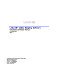
The following figure shows a sample of a network diagram using
ACDB-CLNT and ACDB-SVR software. Note that all
computers running this software must have a HASP key. The
ACDB server connects to the control panels using either a
modem connection or a direct connection (RS-232).
Desktop computer
running ACDB-CLNT
Laptop computer
running ACDB-CLNT
Desktop computer
running ACDB-CLNT
Network
Desktop computer
running ACDB-CLNT
Integrated system
control panel
Integrated system
control panel
RS-232
Main Server
ACDB Server
running ACDB-SVR
Modem
Example network diagram for the ACDB-CLNT and ACDB-SVR
1.6
Access Control Database Administrator Manual
Introduction
Network installation
Begin a network installation with the server. After installing the
ACDB-SVR software, your IT staff should configure DCOM
settings on the server by running the DCOM Configuration tool
as follows.
To configure DCOM settings in Windows 2000:
1. Click Start > Run, then type dcomcnfg and click OK.
This opens the Distributed COM Configuration Properties
dialog box.
2. From the Applications list, select the DataServerComponent
object.
3. Click Properties to open the DataServerComponent
Properties dialog box.
4. Click Security to display the Security tab.
5. Click Use custom launch permissions, then click Edit.
This opens the Registry Value Permissions dialog box.
6. Click Add to open the Add Users and Groups dialog box
7. From the Names list, select the Everyone item.
8. Click Add to add Everyone to the Add Names list.
9. Click OK to close the Add Users and Groups dialog box.
10. Click OK to close the Registry Value Permissions dialog
box.
11. Click Apply to apply your changes.
12. Click OK to close the DataServerComponent Properties
dialog box.
13. Click OK to close the Distributed COM Configuration
Properties dialog box.
To configure DCOM settings in Windows XP:
1. Click Start > Run, then type dcomcnfg and click OK.
This opens the Component Services dialog box.
2. Expand the tree view for Component Services, Computer,
My Computer, and DCOM Config.
3. Scroll down, right-click {B6B18217-F0AB-4F88-9912CEAD40F79E4F} and click Properties.
This opens the {B6B18217-F0AB-4F88-9912CEAD40F79E4F} Properties dialog box.
4. Click Security to display the Security tab.
Access Control Database Administrator Manual
1.7
Introduction
5. In Launch Permissions click Customize, then click Edit.
This opens the Launch Permissions dialog box.
6. Click Add to open the Select Users or Groups dialog box.
7. Click Advance.
8. Click Find Now.
9. If the client server is connected to a peer-to-peer network,
select Everyone from the list.
—or—
If the client server is connected to a true network operating
system (Windows 2000 server), select the individual clients
that will be running the ACDB-CLNT. Repeat steps 7
through 10 for each client of the ACDB.
10. Click OK to add Everyone or the selected individuals to the
Select Users or Groups list.
11. Click OK to close the Select Users or Groups dialog box.
10. Click OK to close the Launch Permissions dialog box.
11. Click Apply to apply your changes.
12. Click OK to close the {B6B18217-F0AB-4F88-9912CEAD40F79E4F} Properties dialog box.
13. Close the Component Services dialog box.
Continue the installation with the client machines. During
installation of the ACDB-CLNT software, you will be prompted
to specify the ACDB server machine by selecting its name.
Changing the network server for an ACDB client
If the ACDB server moved to a new computer, then all ACDB
clients must be modified to connect to the new server. This can
be easily done by choosing Tools > Set Network Server.
1.8
Access Control Database Administrator Manual
Introduction
The Browse for Computer dialog box lets you select the location
of the ACDB server
To change the network server for an ACDB client:
1. From the Tools menu, click Set Network Server.
2. From the Browse for Computer dialog box choose the new
server location.
3. Click OK.
Access Control Database Administrator Manual
1.9
Introduction
System features
The ACDB provides a user-friendly environment for entering
and tracking access control information and for integrating it into
an overall access control system. It makes managing your access
control system easier and more efficient.
The ACDB includes these features:
•
•
•
•
•
•
•
•
•
•
•
•
1.10
Data import from several commonly used databases
Filter-defined cardholder search capability
Cardholder photo import/export
Cardholder import from an external file
Operator defined options (PIN schedule, unlock time)
Administrator definable operator privileges
Access history event log
Database, access event, and presence reports
Predefined and user-defined reports
Muster reports
Task manager to automate routine functions
Encrypted external communications
Access Control Database Administrator Manual
Introduction
Special access
You can specify special access schedules and privileges that
override normal system operations.
The ACDB lets you define and apply three additional schedules
that are specific to individual doors. These door schedules
override the access levels of cardholders. The door schedules
are:
•
•
•
Unlock schedule
PIN schedule
Suppression schedule
Unlock schedules define times when a door is unlocked to allow
free access.
Example: A front door of a retail business open during retail
hours.
PIN schedules define times when a cardholder must enter a PIN
number in additional to presenting a valid access card.
Example: Requiring a PIN at a back door during off-hours can
guard against the use of a stolen card.
Suppression schedules define times normal access granted events
are not logged to history.
Example: During normal office hours you may wish to suppress
access granted events at restroom doors.
Access Control Database Administrator Manual
1.11
Introduction
Setting up the system
The sequence used to set up the Access Control System is very
important. The organization of this manual serves as a guide for
setting up your access control system. It presents the Access
Control Database (ACDB) functions and commands in the order
in which you will use them to set up the system.
The ACDB was designed for three levels of user: administrators,
operators, and cardholders. The administrator has all privileges,
and configures key aspects of the system. The administrator also
creates operators and assigns their privileges. Operators maintain
the cardholder database adding, changing, or removing
cardholders as required. Cardholders are issued access cards and
use the access control system.
If you are an installer or an administrator, follow the general
steps presented below to set up the system. If you are an
operator, proceed to Chapter 8, “Cardholders,” in the Access
Control Database User Manual.
To set up your system:
1. Install the software. Refer to Access Control Database
Software Installation Guide (P/N 3100136). For ACDBCLNT and ACDB-SVR installation, refer to “Network
requirements and installation” in this chapter.
2. Log on to the software. Refer to Chapter 2, “Getting started.”
3. Import the project’s Resource Profile (RP) zip file (if this
was not already done by your installer) or create a
nonintegrated company. Refer to Chapter 3, “Setting up an
integrated access control system” or Chapter 4, “Setting up a
nonintegrated access control system.”
4. Configure the system. Refer to Chapter 6, “Integrated system
and hardware configuration” or Chapter 7, “Nonintegrated
system and hardware configuration.”
Note: To improve the overall performance of the ACDB,
download to the access control system after configuring the
system.
5. Create and set privileges for the operators who will be using
the ACDB software. Refer to Chapter 8, “Operators.”
6. Set up tasks to automate routine functions. Refer to Chapter
9, “Tasks.”
7. Set up the outbound ports and routes. Outbound ports and
routes determine how the ACDB will download information
to the access control system. Refer to Chapter 10, “Outbound
ports and routes.”
1.12
Access Control Database Administrator Manual
Introduction
8. Set up the company’s access schedules. Refer to Chapter 5,
“Schedules” in the Access Control Database User Manual.
10. Set up the company’s holidays. Refer to Chapter 6,
“Holidays” in the Access Control Database User Manual.
11. Set up an access level for each employee group. Attach the
appropriate schedule, privileges, and commands to each
access level created. Refer to Chapter 7, “Access levels” in
the Access Control Database User Manual.
Note: To improve the overall performance of the ACDB,
download to the access control system after creating your access
levels.
12. Set up all the cardholders that will access the building. Each
cardholder must be assigned at least one access level and a
card ID. The access level has a schedule attached to it. The
schedule may or may not have a schedule for holidays. Refer
to Chapter 8, “Cardholders,” in the Access Control Database
User Manual.
Note: To improve the overall performance of the ACDB,
download cardholders after each 100 created.
13. Select and print any of the default reports provided, or create
custom reports for your specific needs. Refer to Chapter 9,
“Reports” in the Access Control Database User Manual.
Access Control Database Administrator Manual
1.13
Introduction
1.14
Access Control Database Administrator Manual
Chapter 2
Getting started
Summary
This chapter defines the process of logging on to the ACDB for
the first time.
Content
Starting the program • 2.2
Logging on for the first time • 2.4
Logging on as an installer • 2.4
Changing the installer password • 2.4
Access Control Database Administrator Manual
2.1
Getting started
Starting the program
The ACDB uses the familiar Windows interface. If you are
familiar with the Windows environment, you should have no
problems using the ACDB.
To run the ACDB program, you must have a software key
(HASP key) on your computer. (No software key is needed for
the KPDISP-CF and ACDB-KE versions.) If no software key has
been installed, follow the instructions in the Access Control
Database Software Installation Guide (P/N 3100136) that comes
with the software.
To start the program:
1. Click Start > Programs > Access Control DataBase > Access
Control DataBase, or double-click the Access Control
DataBase icon on your desktop.
The ACDB displays a progress bar indicating that the program is
starting.
ACDB progress bar at startup
Once the starting sequence is complete, the ACDB displays its
start screen.
The ACDB start screen lets you log on to the software
2.2
Access Control Database Administrator Manual
Getting started
From the start screen, you have four options:
•
•
•
•
Log In
Exit
Help
About
Log In
The Log In option is the entry point for using the software. Users
are issued an operator ID and a password that lets them gain
entry to the program and make modifications to their access
control system.
Exit
The Exit option lets you exit from the program.
Help
The Help option launches an online version of this manual. The
online version includes three navigation tabs:
•
The Contents tab provides a table of contents view of the
help system
•
The Index tab is an alphabetical list of terms. Use the index
to find topics associated with each term.
•
The Search tab lets you search for keywords you enter. This
is generally the fastest method of locating answers to your
questions.
About
The About option brings up a box displaying the current version
of the ACDB software. This information is useful if you decide
to upgrade your software and need to know what version you are
currently running.
Access Control Database Administrator Manual
2.3
Getting started
Logging on for the first time
The system installer is typically an employee of the company
that installed your access control system. Before the ACDB
becomes fully operational, the system installer must log on and
import the Resource Profile (RP) file or create a nonintegrated
company. The RP file is created in the SDU with the Resource
Profile Manager tool. The ACDB does not become fully
functional until the installer imports an RP file or creates a
nonintegrated company.
Logging on as an installer
Before importing an RP file or creating a nonintegrated
company, you can only log on to the ACDB as the installer.
After an RP file is imported or a nonintegrated company is
created, the ACDB creates an administrator ID and a password.
Begin by logging on to the software as the installer.
Note: The initial installer password is 3333. We suggest that you
change the installer password after your initial log on. Make sure
to record and save the revised password in a safe place.
Tip: Operator IDs and
passwords are not case
sensitive so it makes no
difference if you type in all
caps, in lowercase, or a
combination of both.
To log on as the installer:
1. Click Start > Programs > Access Control DataBase > Access
Control DataBase, or double-click the Access Control
Database icon on your desktop.
2. Click Log In on the ACDB splash screen.
3. Type INSTALLER in the Operator ID field.
4. Type the password (3333) into the Password field.
5. Click OK.
The system will log you on as an installer. The installer only sees
a limited view of the software. The installer is prevented from
adding or modifying cardholders, access levels, schedules,
holidays, reports, and operators. This protects the end user from
unauthorized entries to the access system. The primary function
for an installer is to import the RP file.
Changing the installer password
The ACDB recommends that you change the installer password
after your initial log on. Make sure to record the new password
in a safe place.
To change the installer password:
Tip: Press Alt + T, O to
launch the options dialog
box.
2.4
1. From the Tools menu, click Options.
Access Control Database Administrator Manual
Getting started
2. Click the Operator tab.
3. Click the Password Modify button.
4. Type your current password (3333).
5. Type the new password.
6. Retype the new password to confirm it.
7. Click Modify to change the password.
8. Click OK to accept the new password.
After logging on as an installer, your next task is to import an RP
file or create a nonintegrated company. Refer to Chapter 3,
“Setting up an integrated access control system” or Chapter 4,
“Setting up a nonintegrated access control system” for more
information.
Access Control Database Administrator Manual
2.5
Getting started
2.6
Access Control Database Administrator Manual
Chapter 3
Setting up an integrated access control system
Summary
This chapter defines the process for setting up an integrated
access control system, including importing the Resource Profile
(RP) file for your company. Not all of the ACDB’s features and
functions become active until an RP file is imported.
Content
Setting up an integrated access control system • 3.2
Importing an RP file • 3.2
Importing a sample RP file • 3.7
What you should and should not add to the sample
database • 3.7
Importing the real RP file into the sample RP file • 3.9
Removing the sample RP file hardware • 3.10
Logging on after RP file import • 3.11
Importing an RP file into an existing company • 3.12
Modifications to the existing SDU project • 3.12
Importing a new SDU project • 3.13
Upgrading a nonintegrated access control system • 3.16
Merging a nonintegrated CRC • 3.16
Deleting an SDU project and a site • 3.18
Deleting a company • 3.19
Access Control Database Administrator Manual
3.1
Setting up an integrated access control system
Setting up an integrated access control system
By integrated access control system we mean an access control
system that is integrated with a control panel that offers other
services such as fire alarm, security, and access control. The
CRCs and KPDISPs are wired directly to a control panel and
configured using the software definition utility (SDU) for the
panel. The CRC and KPDISP configuration information is
exported out of the SDU and imported into the ACDB as an RP
file.
Note: The ACDB8, ACDB 8+, ACDB-CLNT, and ACDB-SVR
support both integrated and nonintegrated access control
systems. For more information on setting up a nonintegrated
system see Chapter 4: “Setting up a nonintegrated access control
system” and Chapter 7: “Nonintegrated system and hardware
configuration.”
Importing an RP file
The system installer creates RP file using the Resource Profile
Manager tool in the SDU. It is exported out of the SDU and then
imported into the ACDB. The RP file defines the access control
system for the ACDB program. It includes detailed information
about each CRC and KPDISP used in your access control
system. It contains the following:
•
•
•
•
•
•
•
•
•
CRCs, KPDISPs, partitions, and buildings in the system
Routing required to access each device for downloads
KPDISP fire alarm command privileges
Primary company for each CRC
Automatically disarmed partition for each KPDISP
Number of allocated cardholders for each CRC and KPDISP
Number of allocated access levels, schedules, and holidays
for CRCs
Command lists used for CRCs
All MODCOM (integrated system dialer/modem card)
information
After the RP file is imported, the system automatically assigns
an administrator ID and password. The administrator has all
privileges in the ACDB.
Note: The integrated system installer creates the RP file in the
SDU. He may also import the RP file into the ACDB. If the
installer has already imported the RP file, he should have given
the ACDB administrator the administrator ID and password. If
you have been given the administrator ID and password, proceed
to “Logging on after RP file import” later in this chapter.
Your next task is to import an RP file. The integrated system
installer should have given you the RP file for your company.
Each RP file contains the database for a company, a site, and
3.2
Access Control Database Administrator Manual
Setting up an integrated access control system
buildings. This includes all information about partitions, CRCs,
and KPDISPs.
Company
A project can have one or more companies. Each company,
created in the SDU, has a separate RP file. Each RP file is
imported into the ACDB separately. This lets each company
manage their own ACDB database.
Site
A site is directly related to an SDU project. Each SDU project
represents a single site. The ACDB creates a site during the
importing process of the RP file. A company with multiple SDU
projects (in a single location or in multiple locations) has
multiple sites, one site for each SDU project.
Building
Buildings are created in the Resource Profile Manager tool in the
SDU. Partitions, CRCs, and KPDISPs are assigned to the
individual buildings that they reside in.
Depending on your particular configuration, the RP file or RP
files are imported into the ACDB in one of the following
structures:
•
•
•
•
•
•
•
•
One company, one site, and one building
One company, one site, and multiple buildings
One company, multiple sites, and one building
One company, multiple sites, and multiple buildings
Multiple companies, one site, and one building
Multiple companies, one site, and multiple buildings
Multiple companies, multiple sites, and one building
Multiple companies, multiple sites, and multiple buildings
Each RP file represents one site of one company. A large
company may have multiple sites.
Example: A company has two different locations of operation.
One is in New York and the other is in Tennessee. Each site
would have a separate RP file.
Language
The ACDB supports multiple languages. When importing the RP
file, you select the language for the ACDB. This selection sets
the ACDB default language and the language for the ADMIN1
operator.
You can only import one RP file at a time. Importing the first RP
file defines the company. If you have two sites, you import the
second RP file into the existing company.
Access Control Database Administrator Manual
3.3
Setting up an integrated access control system
Note: To import any additional RP files into an existing
company, you must log off as the installer and log on as the
administrator (ADMIN1).
At the end of the import, the ACDB assigns an administrator ID
and password, using the default password ADMIN.
Each company is assigned an administrator ID after the RP file is
imported. You can use this ID and password to begin to add
information to your ACDB system.
The default operator ID is ADMIN1, with password ADMIN.
ADMIN1 is always used for the first company imported into the
ACDB. If a second company is imported, the operator ID is
ADMIN2, again using password ADMIN.
If your integrated system installer has not completed or given
you your RP file, proceed to “Importing a sample RP file” in this
chapter. Importing a sample RP file allows you to begin adding
information to your database while your installer completes your
RP file.
Before using the ACDB you must import an RP file, using the
Import Resource Profile dialog box
To import an RP file:
Tip: Press Alt + F, I, R to
launch the Import
Resource Profile Manager
(RPM) File dialog box.
3.4
1. From the file menu, click Import > RPM Configuration
Information.
2. Locate the RP ZIP file you want to import, select it, then
click Open.
Access Control Database Administrator Manual
Setting up an integrated access control system
If your integrated system installer gave you a floppy disk
containing your RP file, insert the disk and select the RP file
from your floppy drive.
3. Click OK to confirm that the ACDB has extracted your
database.
4. Type a company name if your company name does not
match the company name given.
5. Type a site name.
The site is new, since this is the first RP file import. An
example of a site name is Chicago Campus or North
Campus.
6. Select the language.
7. Click the OK button.
Note: The system displays the administrator operator ID and
password. Write these down in a safe place.
8. Click OK.
Note: To improve the performance of the ACDB and assure
hardware connection, we recommend that you download to the
hardware of your access control system immediately after
importing your RP file. Log on as the administrator to download.
See Chapter 9, “Outbound ports and routes” for information on
configuring the ACDB for downloading.
After you import the RP file the company tree displays the site,
buildings, partitions, CRCs, and KPDISPs
Verify the imported information
After your RP file is imported into the system, you will be able
to see the project tree on the Administration > System tab.
Sites, buildings, partitions, KPDISPs, and CRCs are sub-levels
of the company and their icons are not displayed in the collapsed
tree view. To view all levels of the project, expand the tree view
by clicking the plus signs next to the icons.
Access Control Database Administrator Manual
3.5
Setting up an integrated access control system
You should review the information that your integrated system
installer entered for your company and buildings. We will show
you how to correct any errors in the chapters that follow. It is
important to remember that when you make changes to the RP
file you should contact your integrated system installer to inform
them of the corrections.
For installer contact information, click on the Hardware View
tab and the SDU icon in your company tree.
Since you have just imported your actual RP file, skip the next
topic and proceed to “Logging on after RP file import” in this
chapter.
3.6
Access Control Database Administrator Manual
Setting up an integrated access control system
Importing a sample RP file
If your integrated system installer has not given you an RP file
because it is still being developed, then you can import a sample
RP file. By importing a sample RP file, you can start adding
information to the ACDB database while the installer completes
your RP file.
The sample RP file gives you full access to the ACDB software.
It gives you a visual representation of a company, a site, a
building, a door, and a keypad in the ACDB.
Note: It is important that you do not download information while
the sample RP file is in your database. When you exit from the
ACDB, you are prompted to send hardware updates to the
system. Click No while the sample RP file is in your database.
When you receive your company’s RP file, you need to import it
into the ACDB and then remove the sample RP file hardware.
What you should and should not add to the
sample database
While your real RP file is being completed, you can begin to add
information to your database by importing the sample RP file. It
is important to follow these instructions on what you should and
should not add to the ACDB. Information added that is not listed
will be lost when the real RP file is imported. After you have
imported the sample RP file, log on to the ACDB as the
administrator.
What you can add:
•
•
•
•
Operators
Schedules
Holidays
Cardholders
When adding cardholders, do not download cardholders to the
hardware of your access control system.
What you should not add:
•
•
•
Tasks
Reports
Access levels
Access Control Database Administrator Manual
3.7
Setting up an integrated access control system
When importing a sample file make sure to enter your company’s
name and site
To import a sample RP file:
Tip: Press Alt + F, I, R to
launch the Import
Resource Profile Manager
(RPM) File dialog box.
1. Log on to the ACDB as the installer.
2. From the file menu, click Import > RPM Configuration
Information.
3. Locate the Sample_Company ZIP file in the ACDB
directory, select it, then click Open.
4. Click OK to confirm that the database has been extracted.
5. Type your site name.
The site is new, since this is the first RP file import. An
example of a site name is Chicago Campus or North
Campus. If you do not know your site name, you may enter a
sample site name that can be removed later.
6. Select the Language.
7. Click OK.
Note: The system displays the administrator operator ID and
password. Write these down in a safe place.
8. Click OK.
Note: Once you have imported the Sample RP file, do not
download to the hardware of your access control system.
View the imported information
After importing the sample RP file you can see the project tree
on the Administration > System tab. Sites, buildings, partitions,
KPDISPs, and CRCs are sub-levels of the company and their
icons are not displayed in the collapsed tree view. To view all
levels of the project, expand the tree view by clicking the plus
signs next to the icons.
3.8
Access Control Database Administrator Manual
Setting up an integrated access control system
Importing the real RP file into the sample RP file
The sample RP file is intended for temporary use, while your
real RP file is being completed. The sample RP file lets you
access all features of the ACDB so you can begin to add
information to the ACDB database.
Once you receive the completed RP file, import it into the
ACDB, and then remove the sample RP file hardware. This
removes the sample hardware while preserving any database
entries you’ve already entered.
To import the real RP file into the sample RP file:
1. Log on to the system as the administrator.
Tip: Press Alt + F, I, R to
launch the Import
Resource Profile Manager
(RPM) File dialog box.
2. From the file menu, click Import > RPM Configuration
Information.
3. Locate and select the real RP ZIP file you want to import
then click Open.
If your integrated system installer gave you a floppy disk
containing your RP file, insert the disk and select the RP file
from your floppy drive.
4. Click OK to confirm that the database has been extracted.
5. Click OK to confirm that you are importing a new project
into the ACDB.
6. Click New or Existing for the ACDB site.
When you imported the sample RP file, if you entered a
sample site name then click New and enter the correct name
for your site.
When you imported the sample RP file, if you entered your
correct site name then click Existing and select the site name
from the list.
7. Select the language.
8. In the Options tab, click an Update Option.
Note: The overwrite options does not apply to the hardware of
your access control system. All CRCs and KPDISPs are
overwritten each time you import a new RP file. The overwrite
options only apply to company address and company contact
information, and building address and building contact
information.
9. Click OK.
10. Click OK to confirm the completion of importing.
Access Control Database Administrator Manual
3.9
Setting up an integrated access control system
Removing the sample RP file hardware
Now that you have imported your real RP file, you can remove
the sample RP file hardware from your system. By clicking the
Administration > System > Hardware View tab, you can see two
SDU projects in the tree. One is your real SDU project and one is
labeled Sample R.
You want to remove the Sample R SDU project from your
database. This removes the sample project and all the hardware
associated with it.
After the sample SDU project has been deleted, you can delete
the associated sample site name as required. The site cannot be
deleted until you have deleted the sample SDU project. Deleting
a site removes the site name from the company tree.
To remove the sample RP file:
1. Log on to the ACDB as the administrator.
2. Click Administration > System > Hardware View tab.
3. Select the SDU project labeled Sample R.
4. From the File menu, select Delete or click the Delete button
from the toolbar.
5. Click Yes to confirm the deletion of the SDU project.
6. Click the Company View tab.
7. Select the Sample Site name.
8. From the File menu, select Delete or click the Delete button
from the toolbar.
This removes the sample hardware from your database. You can
now configure your complete ACDB database.
Note: To improve the performance of the ACDB and assure
hardware connection, we recommend that you download to the
hardware of your access control system at this point. See Chapter
10, “Outbound ports and routes” for information on configuring
the ACDB for downloading.
3.10
Access Control Database Administrator Manual
Setting up an integrated access control system
Logging on after RP file import
After the RP file has been imported, you need to log off of the
system as the installer and log on as the administrator, using the
operator ID and password you wrote down.
The ADMIN1 Operator ID is always used for the first company
imported
To log on after an RP file import:
Tip: Operator IDs and
passwords are not case
sensitive so it makes no
difference whether you
type in all caps, in
lowercase, or in a
combination of both.
1. On the Action menu, click Login.
The Login command logs you off as the installer and then
lets you log on as a new operator.
2. Click Login on the ACDB splash screen.
3. Click the OK button to log off as the INSTALLER.
4. Type your operator ID, e.g. ADMIN1.
5. Type your password, e.g. ADMIN.
6. Click OK to log on as the administrator.
Note: The password “ADMIN” should only be used the first
time you log on to the ACDB. Once you log on, we strongly
recommend that you change the password. ADMIN1 is the
operator ID you use to create all other operators. See Chapter 8,
“Operators.”
After you log on, the program displays the ACDB window with
all features and functions active.
Access Control Database Administrator Manual
3.11
Setting up an integrated access control system
Importing an RP file into an existing company
You’ll need to import an RP file into an existing company
whenever:
•
•
You change the configuration of your access control system
You import a new SDU project into your company
Modifications to the existing SDU project
There may come a time when the configuration of your
company’s access control system (referred to as an SDU project)
is changed or modified. Any changes to the company, site,
buildings, partitions, KPDISPs, or CRCs requires an updated RP
file. Import the updated RP file into the existing company and
the existing site. Possible changes include the following:
•
•
•
Changes to the existing hardware of your SDU project
The addition of hardware to your SDU project
The removal of hardware from your SDU project
Note: To import the SDU project into the existing company in
the ACDB, the SDU project must be the same project file that
was originally imported. You cannot recreate the project in the
SDU and then import it into the existing company.
Importing into an existing company is much the same as
importing a new RP file, except that the imported information
goes into the existing company and existing site. This replaces
the old company information with the new information.
Importing an RP file into an existing company and existing site
has no impact on your existing ACDB database.
After the updated RP file has been imported, the ACDB displays
your new hardware configuration in the Administration > System
> Hardware View tab.
Note: You can only import an RP file into an existing company
when logged on to the ACDB as an administrator (ADMIN1).
To modify the existing SDU project:
1. Log on to the system as the administrator.
Tip: Press Alt + F, I, R to
launch the Import
Resource Profile Manager
(RPM) File dialog box.
2. From the file menu, click Import > RPM Configuration
Information.
3. Locate and select the updated RP ZIP file you want to import
then click Open.
If your integrated system installer gave you a floppy disk
containing your RP file, insert the disk and select the RP file
from your floppy drive.
4. Click OK to confirm that the database has been extracted.
3.12
Access Control Database Administrator Manual
Setting up an integrated access control system
5. Click OK.
6. In the Options tab, click an Update Option, then click Done.
Note: The overwrite options do not apply to the hardware of
your access control system. All CRCs and KPDISPs are
overwritten each time you import a new RP file. The overwrite
options only apply to company address and company contact
information, and building address and building contact
information.
7. Click OK.
8. Click OK to confirm the completion of importing.
Importing a new SDU project
If your company has more than one SDU project, both projects
can be maintained in a single ACDB database. Each SDU project
is represented by a single RP file. After the first RP file is
imported, the additional RP files are imported into the existing
company. Both projects are maintained in a single ACDB
database.
There are two ways to import a new SDU project into the
ACDB:
•
•
Import the new SDU project into a new site
Import the new SDU project into the existing site
If your additional SDU project represents a separate location,
then import the RP file into a new site.
Example: A company has two different locations of operation.
One is in New York and the other is in Tennessee. Each site has
a separate RP file both are maintained in a single database.
If your additional SDU project represents a separate project from
the same building, then import the RP file into the existing site.
Example: A large site contains two SDU projects. Each project is
imported into the ACDB separately. Both projects can be
maintained with a single ACDB database.
Note: You can only import an RP file into an existing company
when logged on to the ACDB as an administrator.
Access Control Database Administrator Manual
3.13
Setting up an integrated access control system
Company view with multiple sites New York and Tennessee
To import a new SDU project:
1. Log on to the system as the administrator.
Tip: Press Alt + F, I, R to
launch the Import
Resource Profile Manager
(RPM) File dialog box.
2. From the file menu, click Import > RPM Configuration
Information.
3. Locate and select the updated RP ZIP file you want to import
then click Open.
If your integrated system installer gave you a floppy disk
containing your RP file, insert the disk and select the RP file
from your floppy drive.
4. Click OK to confirm that the database has been extracted.
5. Click OK to confirm that you are importing a new SDU
project.
6. Type the new site or select the existing site then click OK.
Type the new site for a project from a separate location.
Select the existing site if the project is from the same
building.
7. If you selected an existing site, select an existing building
where the project is located.
A project being imported into an existing building can
contain no more than one building.
8. Select the language.
3.14
Access Control Database Administrator Manual
Setting up an integrated access control system
9. In the Options tab, click an Update Option, then click Done.
Note: The overwrite options do not apply to the hardware of
your access control system. All CRCs and KPDISPs are
overwritten each time you import a new RP file. The overwrite
options only apply to company address and company contact
information, and building address and building contact
information.
9. Click OK.
10. Click OK to confirm the completion of importing.
Access Control Database Administrator Manual
3.15
Setting up an integrated access control system
Upgrading a nonintegrated access control system
The ACDB allows you to upgrade a nonintegrated access control
system to an integrated system by allowing merging of CRCs.
Merging CRCs moves all the access control data (access levels,
schedules, and cardholders) from a nonintegrated system to an
integrated system without having to recreate or download the
information. The existing CRCs are simply rewired to the 3-SAC
of the integrated control panel. To upgrade your nonintegrated
access control system begin by following the steps below.
To upgrade a nonintegrated access control system:
1. Upgrade the ACDB-KE to ACDB8, ACDB8+, or ACDBSVR.
2. Back up the ACDB database. See Chapter 5, “Administrator
operations,” for more information.
3. Enter and configure the existing nonintegrated CRCs into the
SDU. Make sure the correct serial number is entered into the
SDU for each existing CRC.
4. Create and export the RP file from the SDU with the existing
CRCs and any additional hardware.
5. Import the RP file into the upgraded ACDB. See “Importing
an RP file into an existing company,” in this chapter.
6. Merge the nonintegrated CRCs into the newly imported
integrated access control system. The ACDB merges the
CRCs with matching serial numbers. See ”Merging a
nonintegrated CRC,” below.
7. Wire the existing nonintegrated CRCs to the 3-SAC on the
integrated control panel.
8. Download from the SDU to the CRCs.
Note: When you download from the SDU to the CRCs, all
cardholder data is removed from the CRC.
9. Run a Hardware Initialization task for each merged CRC.
For more information on the Hardware Initialization task see
Chapter 9, “Tasks.”
Merging a nonintegrated CRC
The ACDB merges nonintegrated CRCs to integrated CRCs by
matching the CRCs serial numbers.
3.16
Access Control Database Administrator Manual
Setting up an integrated access control system
Integrated
access control
system
Nonintegrated
access control
system
The Hardware View, showing both integrated and nonintegrated
systems
The Hardware view clearly shows the existing nonintegrated
access control system and the newly imported integrated access
control system. Each CRC from the nonintegrated system can
now be merged with the integrated system. Merging maintains
all the CRC’s access control information.
To merge a nonintegrated CRC:
1. Log on to the ACDB as the administrator.
2. Click the Administration > System > Hardware View tab.
3. Select the nonintegrated CRC you want to merge.
4. Right-click the nonintegrated CRC then click Merge CRC.
5. Save the CRC information.
Access Control Database Administrator Manual
3.17
Setting up an integrated access control system
Deleting an SDU project and a site
Each RP import represents an SDU project and a site. A
company in the ACDB can contain multiple projects and sites. If
needed, you can delete an SDU project from the ACDB
database. Deleting the SDU project does not delete any data
from the database but removes all buildings, partitions, CRCs,
and KPDISPs associated with the project.
After the SDU project has been deleted, you can delete the
associated site. The site cannot be deleted until you have deleted
the SDU project. Deleting a site removes the site name from the
company tree.
To delete an SDU project and a site you must log on as the
administrator or the installer.
Note: If cardholders have an access level that has CRCs and
KPDISPs in the SDU project being deleted, the cardholder status
may become inaccurate.
To delete an SDU project and a site:
1. Log on to the ACDB as the administrator or the installer.
2. Click the Administration > System > Hardware View tab.
3. Select the SDU icon that you want to delete.
4. From the File menu, click Delete or click the Delete button
on the toolbar.
5. Click Yes to delete the SDU project.
6. Click OK.
7. Click the Company View tab.
8. Select the associated site.
9. From the File menu, click Delete or click the Delete button
on the toolbar.
10. Click OK.
3.18
Access Control Database Administrator Manual
Setting up an integrated access control system
Deleting a company
If needed, you can delete a company from the ACDB database.
A company represents all RP imports including all sites,
buildings, partitions, CRCs, KPDISPs, and MODCOMs.
Deleting the company removes all RP files and data from the
database (cardholders, access levels, schedules, and holidays).
After the company has been deleted, you can import an RP file
that contains the correct information for your company.
To delete a company you must log on to the ACDB as the
installer. Refer to Chapter 2, “Getting started” for information on
how to log on as the installer.
To delete a company:
1. Log on to the ACDB as the installer.
2. Select the company icon that you want to delete.
3. From the File menu, click Delete or click the Delete button
on the toolbar.
4. Click Yes to delete the RP file.
The ACDB shuts down after deleting the RP file. Simply restart
the ACDB to continue operations.
Access Control Database Administrator Manual
3.19
Setting up an integrated access control system
3.20
Access Control Database Administrator Manual
Chapter 4
Setting up a nonintegrated access control system
Summary
This chapter defines the process for creating a nonintegrated
access control system. Not all of the ACDB’s features and
functions become active until a nonintegrated company is
created.
Content
Creating a nonintegrated access control system • 4.2
Creating a nonintegrated company and site • 4.2
Logging on after creating a nonintegrated company • 4.5
Building your nonintegrated access control system • 4.6
Creating a nonintegrated site • 4.6
Creating a nonintegrated building • 4.7
Creating a nonintegrated partition • 4.8
Creating a nonintegrated CRC loop • 4.9
Creating a nonintegrated CRC • 4.11
Deleting components of an nonintegrated access control
system • 4.13
Deleting a nonintegrated CRC • 4.13
Deleting a nonintegrated CRC loop • 4.13
Deleting a nonintegrated partition • 4.13
Deleting a nonintegrated building • 4.14
Deleting a nonintegrated project • 4.14
Deleting a nonintegrated site • 4.14
Deleting a nonintegrated company • 4.16
Access Control Database Administrator Manual
4.1
Setting up a nonintegrated access control system
Creating a nonintegrated access control system
A nonintegrated access control system is made up of a computer
running the ACDB-KE and Card Reader Controllers (CRCs) that
are directly connected to that computer. It is a system where the
company, project, site, buildings, partitions, CRC loops, and
CRCs are created and configured within the ACDB software.
To add a nonintegrated company, you must log on as the
installer. After you add the company, the system automatically
assigns an administrator ID and password. The administrator can
now log on to the software and has all privileges for the ACDB.
Creating a nonintegrated company and site
The ACDB can have one or more companies. Each company can
be nonintegrated or integrated. All nonintegrated companies are
created within the ACDB. To create a nonintegrated company
you must be logged on to the ACDB as the installer.
Each nonintegrated company has an associated site. A site
represents the physical location of the buildings in the access
control system. A company with more than one location will
have one site for each location.
Language
The ACDB supports multiple languages. When creating a
nonintegrated company, you select the language for the ACDB.
This selection sets the ACDB default language and the language
for the ADMIN1 operator.
4.2
Access Control Database Administrator Manual
Setting up a nonintegrated access control system
Sample Company
Before using the ACDB you must create a new company and
site, using the Company Create dialog box
To create a nonintegrated company and site:
1. Log on to the ACDB as the installer.
2. From the file menu, click New Company.
3. Type a company name.
4. Type a site name.
The site is new, since this is a new company. An example of
a site name is Chicago Campus or North Campus.
5. Select the language.
6. Click the OK button.
Note: The system displays the administrator operator ID and
password. Record these in a safe place.
7. Click OK.
After adding a nonintegrated company and site, log on to the
ACDB as the administrator. Once logged on as the administrator,
you can add company information to the ACDB. Company
information includes:
•
•
•
•
Company address
Default card format
Default facility code
Company contact information
Access Control Database Administrator Manual
4.3
Setting up a nonintegrated access control system
You also must be logged on to the ACDB as the administrator to
enter company information, add additional sites, add buildings,
and add CRCs.
4.4
Access Control Database Administrator Manual
Setting up a nonintegrated access control system
Logging on after creating a nonintegrated company
After the nonintegrated company has been created, you need to
log off of the system as the installer and log on as the
administrator, using the operator ID and password you wrote
down.
The ADMIN1 Operator ID is always used for the first company
created
To log on after creating a nonintegrated company:
Tip: Operator IDs and
passwords are not case
sensitive so it makes no
difference whether you
type in all caps, in
lowercase, or in a
combination of both.
1. On the Action menu, click Login.
The Login command logs you off as the installer and then
lets you log on as a new operator.
2. Click Login on the ACDB splash screen.
3. Click the OK button to log off as the INSTALLER.
4. Type your operator ID, e.g. ADMIN1.
5. Type your password, e.g. ADMIN.
6. Click OK to log on as the administrator.
Note: The password “ADMIN” should only be used the first
time you log on to the ACDB. Once you log on, we strongly
recommend that you change the password. ADMIN1 is the
operator ID you use to create all other operators. See Chapter 8,
“Operators.”
After you log on, the program displays the ACDB window with
all features and functions active.
Access Control Database Administrator Manual
4.5
Setting up a nonintegrated access control system
Building your nonintegrated access control system
After you have created a nonintegrated company and logged on
to the ACDB as the administrator, you are now ready to create
the components of your installed nonintegrated access control
system. This includes:
•
•
•
•
•
Sites
Buildings
Partitions
CRC loops
CRCs
In order to accurately create your access control system, you
must know how your system installer has installed the CRCs of
your system. For each CRC you need to know the following:
•
•
•
•
•
The site the CRC is installer in
The building the CRC is installed in
If using partitions, the partition the CRC is in
What loop the CRC is wired to
The CRC serial number and name
Creating a nonintegrated site
Each nonintegrated company has at least one associated site. A
site represents the physical location of the buildings in the access
control system. If your company has more than one location, you
can add additional sites for each location.
Additional sites can be added by right-clicking on your company,
then clicking Add Site
4.6
Access Control Database Administrator Manual
Setting up a nonintegrated access control system
To create a nonintegrated site:
1. Log on to the ACDB as the administrator.
2. Click the Administration > System > Company View tab.
3. Select the company in the company view tree.
4. Right-click the company then click Add Site.
5. Enter a name for the new site in the right pane.
6. Save the site information.
Creating a nonintegrated building
Nonintegrated buildings are created within the ACDB. Partitions
and CRCs are assigned to the individual buildings in which they
reside. Depending on your facility’s configuration your site may
have one or more buildings.
Each building added in the Company View tab adds an
associated project in the Hardware View tab
Once the building has been added, you can enter the building’s
address and contact information. Building information includes:
•
•
Company address
Company contact information
Access Control Database Administrator Manual
4.7
Setting up a nonintegrated access control system
Buildings can be added by right-clicking on your site, then
clicking Add Building
To create a nonintegrated building:
1. Log on to the ACDB as the administrator.
2. Click the Administration > System > Company View tab.
3. Select the site in the company view tree.
4. Right-click the site, then click Add Building.
5. Select the building and add the building information in the
right pane.
6. Save the building information.
Creating a nonintegrated partition
A nonintegrated partition allows you to group CRCs together.
Grouping your CRCs into a nonintegrated partition gives you the
ability to select all the CRCs in that partition for assigning a
schedule. Nonintegrated partitions have no security properties.
Note: The use of nonintegrated partitions is optional.
Nonintegrated partitions should only be used by advanced users
of the ACDB.
4.8
Access Control Database Administrator Manual
Setting up a nonintegrated access control system
Partitions can be added by right-clicking on a building, then
clicking Add Partition
To create a nonintegrated partition:
1. Log on to the ACDB as the administrator.
2. Click the Administration > System > Company View tab.
3. Select the building in the company view tree.
4. Right-click the building, then click Add Partition.
5. Select the partition and edit the partition name.
6. Save the partition information.
Creating a nonintegrated CRC loop
Before adding a CRC you must add a CRC loop. The CRC loop
adds the communication hardware needed for the CRCs to
communicate to the ACDB. When the CRC loop is added, it also
adds a single CRC to the loop. You can configure this CRC as
any door in your system. The hardware that is added to support
each CRC loop is shown in the hardware view. See the figure
below.
Access Control Database Administrator Manual
4.9
Setting up a nonintegrated access control system
Adding a CRC loop adds a computer, a route, and a CRC. The
computer and route are only shown in the Hardware View tab
and not shown in the Company View tab.
The CRC represents a single door in your access control system.
After the CRC loop has been added you can add additional
CRCs to this loop or a new CRC loop.
A CRC loop can be added by right-clicking on your building or
partition, then clicking Add CRC Loop
To create a CRC loop:
1. Log on to the ACDB as the administrator.
2. Click the Administration > System > Company View tab.
4.10
Access Control Database Administrator Manual
Setting up a nonintegrated access control system
3. Select the building or partition in the company view tree.
4. Right-click the building or partition, then click Add CRC
Loop.
5. Enter the serial number for the CRC.
6. Select the new CRC and edit the CRC name (the name of the
door).
7. Save the CRC information.
Creating a nonintegrated CRC
After adding a CRC loop, you can add individual CRCs to the
CRC loop. Each CRC represents a door in your access control
system.
To configure the CRCs refer to Chapter 7, “Nonintegrated
system and hardware configuration.”
Note: Nonintegrated CRCs must have firmware 1.5 or higher.
CRCs can be added by right-clicking on your building, partition or
CRC, then clicking Add CRC
To create a nonintegrated CRC:
1. Log on to the ACDB as the administrator.
2. Click the Administration > System > Company View tab.
3. Select the building, partition or CRC in the company view
tree.
Access Control Database Administrator Manual
4.11
Setting up a nonintegrated access control system
4. Right-click the building, partition, or CRC, then click Add
CRC.
5. Enter the serial number for the CRC.
6. Select the new CRC and edit the CRC name (the name of the
door).
7. Save the CRC information.
4.12
Access Control Database Administrator Manual
Setting up a nonintegrated access control system
Deleting components of a nonintegrated access control system
Just as you can add components within the ACDB, you can also
delete them. You must be logged on to the ACDB as the
administrator to delete CRCs, CRC loops, partitions, buildings,
and sites. To delete a company you must be logged on to the
ACDB as the Installer.
Deleting a nonintegrated CRC
Deleting a nonintegrated CRC removes the door from your
access control system.
Note: If you have downloaded cardholders to a CRC that you
delete, those cardholders will no longer have access to that CRC.
To delete a nonintegrated CRC:
1. Log on to the ACDB as the administrator.
Tip: You can delete a CRC
from the Company View
tab or the Hardware View
tab.
2. Click the Administration > System > Company View tab.
3. Select the nonintegrated CRC that you want to delete.
4. Right-click the CRC, then click Delete CRC.
Deleting a nonintegrated CRC loop
A CRC loop cannot be deleted if more than one CRC exist on
the loop. Deleting a CRC loop removes the computer, the route,
and a single CRC from your access control system.
To delete a nonintegrated CRC loop:
1. Log on to the ACDB as the administrator.
Tip: You can only delete a
CRC loop from the
Hardware View tab.
2. Click the Administration > System > Hardware View tab.
3. Select the nonintegrated route that you want to delete.
4. Right-click the route, then click Delete CRC Loop.
Deleting a nonintegrated partition
You can only delete a partition from the Company View tab.
Deleting a partition removes the partition from the company tree.
Note: Before deleting a partition, remove all CRCs that are in
that partition by assigning them to a building or deleting them.
To delete a nonintegrated partition:
1. Log on to the ACDB as the administrator.
Tip: You can only delete a
Partition from the Company
View tab.
2. Click the Administration > System > Company View tab.
Access Control Database Administrator Manual
4.13
Setting up a nonintegrated access control system
3. Select the nonintegrated partition that you want to delete.
4. Right-click the partition, then click Delete Partition.
Deleting a nonintegrated building
Before you can delete a building, all partitions, CRC loops, and
CRCs in that building must be deleted. Deleting the building
from your access control system removes the building and its
information from the Company View tab.
To delete a nonintegrated building:
1. Log on to the ACDB as the administrator.
Tip: You can only delete a
Building from the Company
View tab.
2. Click the Administration > System > Company View tab.
3. Select the nonintegrated building that you want to delete.
4. Right-click the building, then click Delete Building.
Deleting a nonintegrated project
Each building created in the ACDB has an associated project that
is shown in the Hardware View tab. If needed, you can delete a
project from the ACDB database. Deleting the project does not
delete any cardholder data from the database but removes the
computer, route, partitions, CRC loop, and CRCs associated with
the project.
Note: If you have downloaded cardholders to the CRCs in your
project, those cardholders will no longer have access after the
project is deleted.
To delete a nonintegrated project:
1. Log on to the ACDB as the administrator.
2. Click the Administration > System > Hardware View tab.
Tip: You can also delete a
project from the Hardware
View tab by right-clicking,
then clicking Delete
Project.
3. Select the nonintegrated project that you want to delete.
4. From the File menu, click Delete or click the Delete button
on the toolbar.
5. Click Yes to delete the nonintegrated project.
Deleting a nonintegrated site
Deleting a site removes the site name from the company tree.
Before a site can be deleted all buildings associated with that site
must be deleted.
4.14
Access Control Database Administrator Manual
Setting up a nonintegrated access control system
To delete a nonintegrated site:
1. Log on to the ACDB as the administrator.
2. Click the Administration > System > Company View tab.
Tip: You can also delete a
site from the System View
tab by right-clicking, then
clicking Delete Site.
3. Select the nonintegrated site that you want to delete.
4. From the File menu, click Delete or click the Delete button
on the toolbar.
Access Control Database Administrator Manual
4.15
Setting up a nonintegrated access control system
Deleting a nonintegrated company
If needed, you can delete a company from the ACDB database.
A company represents all objects, both integrated and
nonintegrated, including all sites, buildings, partitions, and
CRCs.
Caution: Deleting the company removes all data from the
database (cardholders, access levels, schedules, and holidays).
After the company has been deleted, you can import a RP file or
create a nonintegrated company that contains the correct
information for your company.
To delete a company you must log on to the ACDB as the
Installer. Refer to Chapter 2, “Getting Started” for information
on logging on as the installer.
To delete a company:
1. Log on to the ACDB as the Installer.
2. Select the company icon that you want to delete.
3. From the File menu, click Delete or click the Delete button
on the toolbar.
4. Click Yes to delete the RP file.
The ACDB shuts down after deleting the company. Simply
restart the ACDB to continue operations.
4.16
Access Control Database Administrator Manual
Chapter 5
Administrator operations
Summary
This chapter introduces you to several administrator operations
of the ACDB. These operations include several basic functions
and several advanced cardholder features. Learning these
functions will help you use the ACDB more effectively and save
you time in your day-to-day work.
Content
Entering a startup screen caption • 5.2
Setting system options and preferences • 5.3
Operator tab • 5.3
Preferences tab • 5.4
Company Information tab • 5.6
UD Cardholder Tab Labels tab and UDF Labels tab • 5.7
Card Code Formats tab • 5.7
Facility Codes tab • 5.7
Saving your changes • 5.8
Downloading information • 5.9
When to download • 5.9
Downloading failure • 5.9
Adding a card format and a facility code • 5.11
Adding a custom card format • 5.11
Adding a facility code • 5.18
Setting the default card format and facility code • 5.19
Administration > System tab • 5.19
Options command • 5.20
Configuring an auxiliary card reader input • 5.22
Scanning in card numbers • 5.23
Assigning central monitoring station user IDs • 5.25
Modifying a CMS user ID • 5.26
Deleting a CMS user ID • 5.27
Exporting a cardholder for badging • 5.28
Exporting a cardholder • 5.28
Exporting additional fields to EPISUITE • 5.29
Changing the EPISUITE database • 5.29
Importing cardholders from an external database • 5.31
Start the database import utility • 5.31
Creating an import definition • 5.31
Assigning import fields • 5.34
Formatting photos • 5.35
Importing the data • 5.36
Backing up your system • 5.39
Restoring a backup database • 5.40
Moving your database to a new PC • 5.41
Exiting from the ACDB • 5.43
Access Control Database Administrator Manual
5.1
Administrator operations
Entering a startup screen caption
When you open the ACDB program, it displays the startup
screen, as shown below. The startup screen has a caption at the
bottom. You can edit the caption to suit your needs. The caption
can contain up to forty characters.
Note: Normally your integrated system installer enters the
caption for you. In order to enter or edit the startup screen
caption you must be log on to the software as the installer. Refer
to Chapter 2, “Getting started” for further information on logging
on as an installer.
Startup screen with sample caption
Entering a startup screen caption:
Tip: Press Alt + T, O to
launch the Option dialog
box.
1. Log on to the ACDB as the installer.
2. From the Tools menu, click Options.
3. Click the Installer tab.
4. In Splash Caption, type the caption text, as you want it to
appear on the start screen.
5. Click Apply.
6. Click OK.
The next time you start the ACDB, the ACDB displays the
modified caption at the bottom of the startup screen.
5.2
Access Control Database Administrator Manual
Administrator operations
Setting system options and preferences
Selecting Options from the Tools menu lets you create and
modify many system options and preferences. These include:
•
•
•
•
•
•
•
Current operator information and password (only appears for
operators with no operator edit privileges)
ACDB preferences for current operator
Company address, contact information, and defaults
User Defined Field (UDF) labels configuration
User Defined (UD) cardholder tab configuration
Card code format configuration
Facility code configuration
Preferences and options dialog box for ADMIN1
Operator tab
The Operator tab only appears for operators with no operator edit
privileges. This tab lets you view information for the operator
currently logged on. You can also change the operator’s
language and password using this tab.
The Operator tab also shows the date and time for the current
operator’s last session. See Chapter 8, “Operators” for detailed
information regarding operators.
Access Control Database Administrator Manual
5.3
Administrator operations
Preferences tab
Preferences are set for the current operator of the ACDB.
Operators can set their own preferences. The Preference tab is
divided into three subtabs:
•
•
•
General
Confirmations
Diagnostics
General tab
The General tab has the following fields:
•
Time Display: Determines whether time is displayed in 12
hour or 24-hour format.
•
Date Display: Determines whether dates are displayed in
short or long date format.
Example of long date: Thursday, January 11th, 2001
Example of short date: 01/11/01
•
Automatic Logout: Sets the program to automatically log
you off after a specified time. Allows changes to be saved or
discarded when automatic logout is engaged.
•
Access Colors: Defines the colors of the time bars used for
schedules. See Chapter 5, “Schedules,” in the Access Control
Database User Manual for detailed information.
In addition there is a group of fields called Miscellaneous
options. This includes:
•
Weeks Start On Sunday: Determines the starting day
(Sunday or Monday) for calendars.
•
Restore to Last Context: To be operational on future releases
of the ACDB.
•
Restore Last Operator ID at Login: Retains your login ID
when logging on to the software.
Confirmations tab
For some actions, the system displays a confirmation dialog box.
You can choose whether or not the system displays confirmation
dialogs for the following actions:
•
•
•
•
•
•
•
5.4
Deleting photos
Adding schedules to an access level
Deleting schedules to an access level
Setting privileges to an access level
Resetting privileges to an access level
Adding command lists to an access level
Deleting command lists from an access level
Access Control Database Administrator Manual
Administrator operations
Diagnostics tab
The Diagnostics tab provides diagnostic information for client
activity within the ACDB. It contains three check boxes.
•
•
•
Trace Client Program Activity
Dump Server Trace On Server Close
Compact Database on Server Close
Only use Trace Client Program Activity and Dump Server Trace
on Server Close when directed by technical support.
Compact Database on Server Close ensures optimal performance
of the ACDB and should be performed on a regular basis. As
you run the ACDB, the database can become fragmented and use
disk space inefficiently. When you check Compact Database on
Server Close, the ACDB compacts the database and rearranges
files more efficiently when you exit the program. The Compact
Database on Server Close is cleared each time you exit from the
ACDB, and must be checked each time you want to compact the
database.
Note: Compact is automatically performed when you backup the
ACDB database. For more information, see “Backing up your
system” in this chapter.
The Diagnostics tab lets you compact your ACDB database
when the application is closed
Access Control Database Administrator Manual
5.5
Administrator operations
Company Information tab
The Company Information tab has two subtabs, General and
Defaults. The General tab is for company address, contact
information, and default language. The Default tab is where the
default card format and facility code are set. The Default tab also
offers a configuration button for an auxiliary card reader input.
General tab
Company information is the information specific to the owner
and controller of the entire site. This information includes the
company address and contact information.
Typically, the Resource Profile (RP) file provides company
information. The company information is imported into the
ACDB along with your access control system information, but
you can revise the imported information as required. See Chapter
3, “Setting up an integrated access control system” for further
information.
The ACDB supports multiple languages. The language set for
the company is the default language for each operator of the
ACDB. Operator languages can be changed for each individual
operator.
Note: If you make changes to the company information, contact
your integrated system installer and inform him of the
corrections. For installer contact information, click the Hardware
View tab and the SDU icon in your company tree. The installer
will need the information to correct his records for future contact
with you.
Default
For each cardholder you assign a card format and possibly a
facility code. Some cards formats do not require a facility code.
The majority of cardholders will be using the same card format
and facility code. Once you know the card format and facility
code for your access control system, you can set them as the
defaults.
Each new cardholder added will be assigned the default card
format and facility code. This avoids having to select the same
card format and facility code for every new cardholder.
For further information on setting the default card format and
facility code, refer to “Setting the default card format and facility
code,” in this chapter.
You can also configure an auxiliary card reader input. A card
reader input device gives you the ability to scan a card number
into the cardholder file, instead of manually entering it. The card
is simply scanned with a standard card reader and the card
number is inserted into the cardholder file. For further
5.6
Access Control Database Administrator Manual
Administrator operations
information on configuring an auxiliary card reader input, refer
to “Configuring an auxiliary card reader input,” in this chapter.
UD Cardholder Tab Labels tab and UDF Labels tab
The next tabs are the User Defined (UD) CardHolder Tab Labels
and User Defined Fields (UDF) Labels. These tabs let you define
additional custom tabs and fields for cardholders. The UD
cardholder tab label lets you define up to three custom
cardholder tabs. Each tab supports ten custom fields.
The UDF Labels tab lets you define up to ten custom fields per
tab. This lets you customize the field labels for your unique
requirements. The fields can be labeled for internal company
training dates, pay levels, or contact information.
For further information, see Chapter 8, “Cardholders,” in the
Access Control Database User Manual.
Card Code Formats tab
The ACDB supports access cards in standard Wiegand formats.
The Wiegand format is binary encoded data that uniquely
defines cardholders across multiple sites and companies.
The following list shows the card formats defined for you by the
ACDB. These card formats can not be modified.
•
•
•
•
•
•
26 Bit Wiegand Compatible
26 Bit Wiegand SIA Compatible
26 Bit Wiegand Standard
32 Bit Wiegand Compatible
34 Bit Wiegand Compatible
38 Bit Wiegand Compatible
If your access cards are in a different card format than the ones
listed above, you can create a custom card format. See “Adding a
card format and a facility code,” in this chapter for detailed
information on how to add a custom card code format.
Facility Codes tab
Some access card formats need a facility code to complete their
access card number. The ACDB adds the facility code to the
access card number when downloaded to the hardware of your
access control system. Facility names and facility codes are
specified in Tools > Options > Facility Codes.
The Facility Codes tab provides a listing of the codes currently
used in your system. You may add to this list or delete facility
codes no longer in use. See “Adding a card format and a facility
code,” in this chapter.
Access Control Database Administrator Manual
5.7
Administrator operations
Saving your changes
Tip: A tab with an asterisk
(*) on either side of the tab
name shows that
information on the tab has
been modified but not
saved.
When the information is
saved the asterisks are
removed.
Saving is very important to maintain correct and current data in
your access control system. Saving is the only way to update the
database with any changes or additions that you make. An item
is not recognized as a permanent record until it is saved.
To save your changes:
1. On the File menu, click Save, or click the Save button on the
toolbar.
Note: When you save data within a tab of the ACDB, only the
information in that tab is saved.
Tip: Press Alt + F, S to
save.
5.8
If information is not saved and you try to exit from the ACDB, a
dialog box is displayed reminding you to save before exiting.
Access Control Database Administrator Manual
Administrator operations
Downloading information
Once information has been entered into the ACDB, the data must
be downloaded to your access control system. Only after the
information has been downloaded will cardholders be able to
gain access.
Any time changes are made to the ACDB that affect your access
control system, the revised data must be downloaded to your
access control system. No changes will be active in the CRCs or
KPDISPs until they are downloaded.
Each time the ACDB communicates with a nonintegrated CRC,
the time in the CRC is updated to the current time of the PC
running the ACDB-KE.
For you to be able to download to the CRCs and KPDISPs, the
Outbound port and Route of the ACDB must be configured. For
further information, see Chapter 10, “Outbound ports and
routes.”
You can download changes to your system at any time or from
any tab within the software. Make sure all information has been
saved before downloading.
Note: Construction cards will no longer allow access once data
is downloaded to the CRCs.
To download changes to CRCs and KPDISPs:
1. From the File menu, click Send Changes, or click the Send
Changes button on the toolbar.
Note: For integrated systems, verify that the date and time are
correct at the system panel. An incorrect date and time causes
incorrect operation of the access control system.
When to download
To improve the performance of the ACDB, we recommend that
you download at specific times while setting up your database.
Here are the times when you should download.
•
After importing your company’s RP file or setting up your
nonintegrated access control hardware
•
After creating and activating each 100 cardholders
Downloading failure
When a yellow X is displayed over a CRC or KPDISP this
indicates that the system failed to download to this CRC or
KPDISP. This can be seen from the tree view in the Access
Levels tab and the Administration > System tab.
Access Control Database Administrator Manual
5.9
Administrator operations
If you see a yellow X over a CRC or a KPDISP, confirm that the
device has not been removed from your system and that it is
functioning properly. Also, confirm that you have configured
your outbound ports and routes properly.
The yellow X over CRC3 shows that the ACDB could not
download to it because of a communication error
5.10
Access Control Database Administrator Manual
Administrator operations
Adding a card format and a facility code
When a cardholder’s access card is downloaded to a CRC, the
ACDB sends a derived bit code that has been translated
according to the card format. The card format translates the card
number into a string of bits that the CRC recognizes when the
access card is presented.
Some existing access cards include a facility code. If your access
card includes a facility code, it can be added to the card format.
This is dependent upon the access card being used.
The ACDB contains definitions for the Wiegand card formats.
These formats can not be edited or deleted. They are:
•
•
•
•
•
•
26 Bit Wiegand Compatible
26 Bit Wiegand SIA Compatible
26 Bit Wiegand Standard
32 Bit Wiegand Compatible
34 Bit Wiegand Compatible
38 Bit Wiegand Compatible
Adding a custom card format
The ACDB contains definitions for the Wiegand card codes. If
your company’s access cards have a different card format than
the ones given, you can create a custom card format.
The card format can be broken down into four parts:
•
•
•
•
Card ID
Facility code
Constant bit
Parity bit
Note: When you create a custom card format, it is important to
remember that the CRC evaluates only the first 32 characters of
the card number. This means you must design your format so
that the unique portions of the card number appear within the
first 32 positions of the card format.
Access Control Database Administrator Manual
5.11
Administrator operations
The Card Code Format Editor dialog box lets you create a
custom card format
The Card Code Format Editor toolbar buttons
The Card Code Format Editor dialog box provides buttons to aid
you in adding, modifying, and deleting constant bits and parity
bits.
Button
Command Description
Insert One
Bit
Inserts a one bit before or after the card
ID or facility code. The one is constant
and does not change.
Insert Zero
Bit
Inserts a zero bit before or after the
card ID or facility code. The zero is
constant and does not change.
Toggle Bit
Toggles the constant bit from one to
zero and zero to one.
Toggles the parity bit from even to odd
and odd to even.
Insert Even Inserts an even parity bit before or after
Parity
the card ID or facility code
5.12
Insert Odd
Parity
Inserts an odd parity bit before or after
the card ID or facility code
Delete Bit
Removes any bit from the card code
format
Minimum
set button
Sets the card format to a minimum of
eight card ID bits
Standard
26 bit
Wiegand
set button
Sets the card format to the Wiegand
standard 26 bit format. You can use this
as a starting point to create a custom
format.
Access Control Database Administrator Manual
Administrator operations
Note: The card ID, facility code, constant bit, and parity bit can
not total more than 64 bits.
To add a custom card format, you need to:
1.
2.
3.
4.
5.
Create a new card format.
Specify the card ID format.
Specify the facility code format.
Specify the constant bits.
Specify the parity bits.
Details of each step are given below.
Creating a new card format
If your company’s access cards have a different card format than
the card formats given, you can create a new card format. All
new card formats are created using the Options dialog box.
A new card format is added by clicking the new button on the
Card Code Formats tab
To create a new card format:
Tip: Press Alt + T, O to
launch the Options dialog
box.
1. From the Tools menu, click Options.
2. Click the Card Code Formats tab.
3. Click the New button.
4. Type a name for the card format.
Access Control Database Administrator Manual
5.13
Administrator operations
Specifying the card ID format
The card ID can have between 4 and 63 bits. It can be one of
four data types: standard, binary coded decimal (BCD), BCD 8,
or ASCII.
The Test Value box lets you enter a test card ID value. The
translated value is displayed for you in the Test Value Result
box.
Card Code Format table with a sixteen-bit card ID
To specify the card ID format:
1. In the Card ID Size box, scroll up or down to select the bit
size of the card ID. In the Card Code Format table below, the
format row displays a C for each card ID bit added.
2. In the Data Type box, click Standard, BCD (Binary Coded
Decimal), BCD 8, or ASCII.
3. Type a test value for the card ID (optional).
Specifying the facility code format
The facility code can have between 1 and 32 bits. The facility
code can be added to the beginning or end of the Card ID. It can
be one of four data types: standard, BCD, BCD 8, or ASCII.
The Test Value box lets you enter a test facility code value. The
translated value is displayed for you in the Test Value Result
box.
Tip: You can simulate a 64-bit Card ID format by specifying a
63-bit Card ID and a 1-bit constant in position 1.
5.14
Access Control Database Administrator Manual
Administrator operations
Card Code Format table with a sixteen-bit card ID and an eightbit facility code placed before the card ID
To specify the facility code format (optional):
1. In the Card Code Format table select the cell in the table
where you would like the facility code to be placed. If the
facility code is to be placed before the card ID, select a cell
in the first half of the card ID. If the facility code is after the
card ID, select a cell in the last half of the card ID.
2. In the Facility Size box, scroll up or down to select the bit
size of the facility code. Depending on where you have
selected the cell in the table, the facility code bits are added
to the front or back of the card ID.
3. In the Data Type box, click Standard, BCD (binary coded
decimal), BCD 8, or ASCII.
4. Type a test value for the facility code (optional).
Specifying the constant bits
A constant bit is a positive (0) or negative (1) bit that does not
change its value. It can be positioned before or after the card ID,
or before or after the facility code.
Access Control Database Administrator Manual
5.15
Administrator operations
Card Code Format table with a sixteen-bit card ID, an eight-bit
facility code, and a one constant bit placed after the card ID
To specify the constant bit (optional):
1. In the Card Code Format table select the cell in the table
where you would like the constant bit to be placed. The
constant bit can be placed before or after the card ID or the
facility code.
2. Click the Insert One Bit button or the Insert Zero Bit button
from the Card Code Format Editor toolbar. A constant bit is
added to the Card Code table on the Constant row. Where
the bit is placed is based on the position you have selected in
the table.
Specifying the parity bit and setting the parity mask
A parity bit is an even (E) or odd (O) bit that can be positioned
before or after the card ID, or before or after the facility code.
You can include facility bits, card ID bits, and constant bits in
the calculation of the parity bit. This is called the parity mask.
The parity mask is the facility bits, card ID bits, and constant bits
that are placed on the parity row.
5.16
Access Control Database Administrator Manual
Administrator operations
Card Code Format table with a sixteen-bit card ID, an eight-bit
facility code, a one constant bit placed after the card ID, and a
even parity bit placed in column 1. The parity mask for the even
parity is defined by columns 2 through 13 on parity row one.
To specify the parity bit and the parity mask (optional):
1. In the Card Code Format table select the cell in the table
where you would like the parity bit to be placed. The parity
bit can be placed before or after the card ID or the facility
code.
2. Click the Insert Even Parity button or the Insert Odd Parity
button. An E (even) or an O (odd) parity bit is added to the
Card Code Format table on a Parity row. Where the bit is
placed is based on the position you have selected in the
table. Each parity bit that is added creates a new parity row.
3. Define the parity mask by adding facility bits, card ID bits,
and constant bits to the parity row. You can do this by
right—clicking the parity row and dragging the mouse
across the columns you wish to add.
4. Click OK to save the new card format.
5. Click Apply.
6. Click OK.
Note: If most of your cardholders will be using this card code
format, make it the default. See “Setting the default card format
and facility code” in this chapter.
Access Control Database Administrator Manual
5.17
Administrator operations
Adding a facility code
An access card may or may not include a facility code. Facility
codes provide extra security so that access card IDs have less
chance of being duplicated at different facilities.
The facility codes are assigned to a cardholder from the
Cardholder tab.
The Facility Codes tab lets you define facility codes
To enter a new facility code:
Tip: Press Alt + T, O to
launch the Options dialog
box.
1. From the Tools menu, click Options.
2. Click the Facility Codes tab.
3. Click the New button.
4. In the Name column, type a name for the facility code.
5. In the Code column, type a code for the facility code.
6. Click OK.
7. Click Yes to save the facility code.
Note: If most of your cardholders will be using this facility code,
make it your default. See “Setting the default card format and
facility code” in this chapter.
5.18
Access Control Database Administrator Manual
Administrator operations
Setting the default card format and facility code
Each cardholder is assigned a card format and possibly a facility
code. The majority of cardholders use the same card format and
facility code. You can set these as the defaults.
Each new cardholder is automatically assigned the default card
format and facility code. This eliminates the need to select the
card format and facility code for every new cardholder.
If you are importing cardholders from an external source, make
sure to set the default card format and facility code before
importing the cardholders. All imported cardholders are assigned
the default card format and facility code.
There are two ways to set the default card format and facility
code:
•
•
Using the Administration > System tab
Using the Options command in the Tools menu
Administration > System tab
The default card format and facility code can be set using the
Administration > System tab.
Setting default card format and facility code from the
Administration > System tab
To set the defaults using the System tab:
1. Click the Administration tab.
2. Click the System tab.
3. Select the company name in the tree.
Access Control Database Administrator Manual
5.19
Administrator operations
4. In the Default Card Format list, select the card format that
your company will be using most often.
5. In the Default Facility Code list, select the facility code that
your company will be using most often.
Options command
The default card format and facility code can also be set using
the Options command on the Tools menu.
Setting the defaults using the Tools > Options dialog box
To set the defaults using the Options dialog box:
Tip: Press Alt + T, O to
launch the Options dialog
box.
1. From the Tools menu, click Options.
2. Click the Company Information tab.
3. Click the Default tab.
4. In the Default Card Format list, select the card format that
your company will be using.
5. In the Default Facility Code list, select the facility code that
your company will be using.
Note: If the card format or facility code is not listed, you can
create a new one. Click the New button to the right of the
appropriate list. The New buttons open the Card Code Format
tab or the Facility Code tab. You can create a new card format or
5.20
Access Control Database Administrator Manual
Administrator operations
facility code using these tabs. See “Adding a custom card format
and facility code” in this chapter.
Access Control Database Administrator Manual
5.21
Administrator operations
Configuring an auxiliary card reader input
A card reader input device lets you scan a card ID into the
cardholder’s record, rather than entering it manually. You scan
the card with a standard card reader and the ACDB inserts the
card ID into the cardholder record.
The ACDB is designed to work with the Cypress CVX-1200
MultiBender converter. The Cypress converter connects directly
to the serial port of your computer. Any Wiegand output card
reader connects to the Cypress converter. For installation, follow
the manufacturer’s instructions.
After installing the Cypress converter, you must configure the
ACDB for the auxiliary reader input. Configuration must be
done before access cards can be scanned into cardholder records.
Configuration dialog box for an auxiliary card reader. The ACDB
is compatible with the Cypress CVX-1200 MultiBender converter.
To configure an auxiliary card reader:
Tip: Press Alt + T, O to
launch the Options dialog
box.
5.22
1. On the Tools menu, click Options.
2. Click the Company Information tab.
3. Click the Default tab.
Access Control Database Administrator Manual
Administrator operations
4. Click the Configure button for Configuring Auxiliary Card
Reader Input.
5. In Pick Input Device group, click Serial Port Input Reader.
6. Click OK to save your configuration settings.
Scanning in card numbers
After the Cypress converter is installed and the ACDB is
configured, you are ready to scan a card ID directly into the
cardholder records.
To scan a card ID into the cardholder record click the Swipe
button
When an access card is scanned with the Cypress converter, the
ACDB displays a table with the possible card formats that match
the access card. The table contains columns that display the
following:
•
•
•
•
•
•
•
Card ID number
Facility code number
F.C. exists
Derived card number
Card number read
Number of bits
Card format
Select the row from the table that matches the card format of
your access card. If the scan revealed a facility code, the facility
code must be created before the ACDB will accept the access
card. If the F.C. Exists column displays False, you must then
create a facility code to match the number displayed in the
Facility column. If the F.C. Exists column displays True, the
facility code already exists in the ACDB.
In the example below, the scan revealed a 26 bit Weigand card
format. The ACDB has three possible card formats that match
the 26 bit format. Simply select the card format that matches
your access card. All three card formats displayed require a
facility code to be entered before the card can be accepted into
the ACDB.
Access Control Database Administrator Manual
5.23
Administrator operations
The ACDB matches the access card to compatible card formats
To scan a card number:
1. Click the Cardholder tab.
2. In the left pane, select the cardholder whose card you want
to scan.
3. Click the Swipe button next to the ID field.
4. Scan the card with the auxiliary card reader.
5. Select the row that matches your access card.
6. Save the cardholder record.
5.24
Access Control Database Administrator Manual
Administrator operations
Assigning central monitoring station user IDs
When an access event is reported to a central monitoring station
(CMS), the CMS uses the assigned user ID to identify the
cardholder that created the event.
Your site may report events to several CMSs or alphanumeric
pagers. A cardholder can have multiple CMS user IDs, but each
ID must be unique for a given CMS account.
The CardHolder > System tab lets you assign a CMS user ID to a
cardholder. A single cardholder can have up to three user IDs.
Each CMS has an account for your company. The CMS accounts
are created by your installer and imported with your RP file. You
can have multiple CMS accounts and a corresponding CMS user
ID for each cardholder.
Example: A cardholder creates an after-hours irregular access
event into a controlled partition. The cardholder’s access level
has a command list that reports all irregular access events to the
CMS. The message would include the event and the cardholder’s
CMS user ID, so that the CMS could identify the person.
After assigning CMS user IDs to all cardholders, you need to run
the User ID Translation Report and send it to the CMS. See
Chapter 10, “Reports” for more information on the User ID
Translation Report.
Note: Using a CMS account requires coordination between the
ACDB and the integrated system. Contact the installer of your
access control system for further information.
Access Control Database Administrator Manual
5.25
Administrator operations
The CardHolder > System tab lets you assign CMS user ID
numbers to individual cardholders
To assign a CMS user ID:
1. Click the CardHolder > System tab.
2. In the left pane, select the cardholder to whom you want to
assign a CMS user ID.
3. In the CMS Account list, select the CMS account for which
you want to assign a user ID.
4. Click the New button next to the CMS Account field.
The ACDB assigns the next available CMS user ID number
to the cardholder.
5. Save the cardholder record.
Note: If all CMS user IDs have been assigned to cardholders, the
ACDB will create groups of cardholders, sharing the same user
ID.
Modifying a CMS user ID
You can modify a CMS user ID. After you modify the user ID,
be sure to notify the CMS of the new user ID. You may want to
send a copy of the User ID Translation Report.
5.26
Access Control Database Administrator Manual
Administrator operations
If the CMS user ID is already used by another cardholder, the
ACDB displays a message. Choose another user ID that is not in
use.
To modify a CMS user ID:
1. Click the CardHolder > System tab.
2. In the left pane, select the cardholder whose CMS user ID
you want to modify.
3. In User ID, type the new ID.
4. Save the cardholder record.
Deleting a CMS user ID
If your company switches CMS accounts or no longer wants to
use a CMS account, the CMS user ID for that account can be
deleted from a cardholder record.
To delete a CMS user ID:
1. Click the CardHolder > System tab.
2. In the left pane, select the cardholder from whom you want
to delete a CMS user ID.
3. Click the Delete button next to the User ID field.
The ACDB removes the CMS account and user ID from the
cardholder.
4. Save the cardholder record.
Access Control Database Administrator Manual
5.27
Administrator operations
Exporting a cardholder for badging
Badging is the process of creating an identification card for an
individual. Typically, the identification card includes a
cardholder photo.
The ACDB has the option of using EPISUITE software to create
badges. EPISUITE is a feature-rich electronic photo
identification system used to create and print badges. The
EPISUITE software and badge printing equipment must be
purchased separately. Contact your installation company for
purchasing information.
See EPISUITE literature for software support and compatible
badge printers. The ACDB is compatible with EPISUITE
versions 5.0, 5.5, and 6.0. The EPISUITE software must be
installed on the same computer as the ACDB. Network
EPISUITE applications are not supported, but normally you will
only need one badging workstation.
Exporting a cardholder
You must install the EPISUITE software on the same computer
as the ACDB to activate the Badge button on the CardHolder
tab.
When you click the Badge button on the CardHolder tab, the
following ACDB fields are exported to the corresponding
EPISUITE fields:
5.28
ACDB
EPISUITE
Title
Title
First Name
First Name
Last Name
Last Name
Address Line 1
Address
City
City
State
State
ZIP
ZIP Code
Country
Country
Phone Number Home
Home Phone
Phone Number Business
Work Phone
IDs Company
Company
IDs Employee
Employee Number
Card ID
Person ID
Photo
Photo
Access Control Database Administrator Manual
Administrator operations
Each cardholder is added to the end of the EPISUITE database.
If the new cardholder is not displayed at the end of the database,
verify that EPISUITE is using the database EPISUITE.mdb. See
“Changing the EPISUITE database” below.
Tip: By using the
multiselect toolbar buttons
or the multiselect action
menu items, you can select
multiple cardholders for
export. All selected
cardholders can be
exported at one time.
To export a cardholder:
1. Click the CardHolder tab.
2. In the left pane, select the cardholder to be badged.
3. Click the Badge button below the photo of the cardholder.
The ACDB starts the EPISUITE Guard Card program and
exports the selected cardholder.
4. Click the EPISUITE Refresh button. The new cardholder is
added to the end of the EPISUITE database.
5. Select the new EPISUITE cardholder and proceed with the
EPISUITE instructions for creating and printing badges.
Exporting additional fields to EPISUITE
If you would like to export additional fields to EPISUITE, create
the fields as UDFs in the ACDB. Make sure that the label of
your UDF matches the EPISUITE field label exactly. When you
click the export button the ACDB will match the identical fields
and export the data.
To export additional fields to EPISUITE:
1. Create a User Defined Field (UDF) in the ACDB that
exactly matches the field in EPISUITE. See Chapter 8,
“Cardholders” in the Access Control Database User Manual
for information on how to create a UDF.
Example: EPISUITE has a field called Department. Create a
UDF in the ACDB called Department.
2. Export a cardholder from the ACDB to EPISUITE, with data
in the newly created matching UDF.
Example: Data entered in the UDF Department field in the
ACDB is exported to EPISUITE Department field.
Changing the EPISUITE database
When installing the EPISUITE software, you can install it with a
blank database or a sample database. If the software was
installed with a blank database, EPISUITE uses the file
TEMPLATE.mdb as its database. If the software was installed
with a sample database, EPISUITE uses the EPISUITE.mdb file
as its database. The ACDB exports to EPISUITE.mdb file.
Access Control Database Administrator Manual
5.29
Administrator operations
Make sure that GuardCard is using the EPISUITE.mdb file by
clicking View > Options > Database in the EPISUITE software.
If the EPISUITE.mdb file is not being used, you can change the
database by clicking Change Database and navigating to the
EPISUITE.mdb file.
To change the EPISUITE database:
1. Log on to the EPISUITE Guard Card program.
2. On the View menu, click Options.
3. Click the Database tab.
4. Click Change Database.
5. In Use and Access (Jet) database, click the Browse button.
6. Navigate to the EPISUITE.mdb file and select it.
Note: The EPISUITE.mdb file is in the same directory as the
TEMPLATE.mdb file.
7. Click Open, click Open and click Ok.
5.30
Access Control Database Administrator Manual
Administrator operations
Importing cardholders from an external database
The ACDB lets you import cardholders from an external source.
You may already have cardholders entered into a card access or
human resource program. Rather than having to reenter the
cardholder information into the ACDB, you can move data from
an external database to the ACDB database. This offers a huge
saving in time and resources when first setting up your access
control system.
The database import utility lets you match fields from your
existing database to fields in the ACDB. You can import files
from any OLE DB Providers installed on your PC.
When importing cardholders from an external source, make sure
to set the default card format and facility code before importing
the cardholders. All imported cardholders are assigned the
default card format and facility code.
Note: Importing data from an external source is an advanced
procedure, which requires knowledge of Open Database
Connectivity (ODBC). Consult with your company’s IT
professional about ODBC issues.
The procedures that follow are based on the import of a
Microsoft Access database. In general, you will follow these
steps to import cardholder data:
1.
2.
3.
4.
5.
Start the database import utility.
Create an import definition.
Assign import fields.
Format photos.
Import the data.
Start the database import utility
All import procedures start from the Database Import Utility
dialog box. All the procedures described below start and end at
this dialog box.
To start the database import utility:
1. Click File > Import > External Card Holders.
Creating an import definition
Before you can import a database, you must create an import
definition for the external database. The import definition
defines what type of data is being imported and where the file is
located. It also lets you select the database table you want to
import.
Access Control Database Administrator Manual
5.31
Administrator operations
You can create multiple import definitions for external
databases. This can be from the same database or different
databases.
You will follow these steps to create an import definition:
1. Create a new import definition.
2. Create a connection string.
3. Select the database table to import.
The Import Source Properties dialog box defines what type of
data is being imported and where the file is located
Creating a new import definition
To create a new import definition:
1. In the Database Import Utility dialog box, click Source.
2. Click New.
3. Type a name for the import definition.
4. Click OK.
Creating a connection string
The connection string identifies the source database you want to
import. By clicking the Browse button (...), you open the Data
Link Properties dialog box. The Data Link Properties dialog box
shows the OLE DB providers that are installed on your PC. For
more information, click the Help button in the Data Link
Properties dialog box.
Example: If your existing database is a Microsoft Access file
(file extension: MDB), then you will use the Microsoft Jet 4.0
OLE DB Provider. On the Connection tab, identify where your
Microsoft Access database file is located and any log on
information for the file.
Note: The following dialog boxes represent the example given.
Your dialog boxes may vary depending on your system and on
the database provider chosen.
5.32
Access Control Database Administrator Manual
Administrator operations
Typical Data Link Properties dialog boxes for Microsoft Access
To create a connection string:
1. In the Connection String group, click the Browse button (...).
2. Select the OLE DB Provider for your external database.
3. Click Next.
4. Fill in the Connection tab information.
5. Click OK.
Selecting the database table to import
Once you have established the connection string for the external
database, you need to select a specific table from the database.
This table contains the data you want to import into the ACDB.
Controls in the Configure Source Table group let you select any
of the tables from the database or write an SQL statement.
Once you select the table from the database, the system displays
the field names or the field values of the table. The field names
or field values are displayed in the Available Fields list. This
makes it easy to verify that you have selected the correct table
for import. The field values are the actual data that the fields
contain. If the field names and values do not appear to be the
data you want to import, the source table may not be correct. Use
the Configure Source Table controls to select the correct table.
Access Control Database Administrator Manual
5.33
Administrator operations
After creating a connection string, you select a database table.
The system displays the fields in the table.
To select the database table:
1. In the Configure Source Table group, click SQL to create a
query, or click the list box to select a table.
2. If you clicked SQL, click Edit and write the SQL Statement.
If you clicked the selection list, select the table from which
you want to import the data.
3. In the Display group, click Field Names and verify that the
fields are the fields you want to import. The fields are
displayed in the Available Fields list.
Note: The fields displayed are the fields available for import.
You decide which fields are actually imported in the step
“Assigning import fields,” shown below.
4. In Display group, click Field Values and verify that the
fields contain the data you want to import.
Note: You can scroll through different records by clicking
the forward and backward arrow buttons. The data is
displayed in the Available Fields list.
5. Click Save to save your import definition.
6. Click Close to close Import Source Properties dialog box.
The system returns you to the Database Import Utility dialog box
for the next step in the process.
Assigning import fields
The Database Import Utility dialog box lets you select which
fields you want to import and where you would like the data to
be stored in the cardholder record.
After you select an import definition, the fields from the external
database are displayed in the Unassigned External Fields column
on the left. Each of these fields can be dragged to the Crossed
Field Name column. Drag the field to the corresponding row in
5.34
Access Control Database Administrator Manual
Administrator operations
the CH Display Name column. This is where the imported field
will be stored and displayed in the ACDB.
You control the source and destination of imported data by
clicking and dragging the external fields to the crossed field
name column
To assign import fields:
1. From the bottom left list, select the import definition you
want to use.
2. From the Unassigned External Fields list, drag each field
you want to import into the Crossed Field Name column.
Place it beside the CH Display Name (ACDB) in which the
data should be stored.
Note: The CH Display Name is where the imported data will
be stored in the ACDB. Not all fields need to be dragged
from the Unassigned External Fields column to the Crossed
Field Name column. Only drag the fields you want to import
into the ACDB.
Formatting photos
If your external database includes photos for import, you can edit
the import properties for the photos. The Image button becomes
active as soon as a crossed field name is dragged to the photo
row. The Image button opens the Set Photo Properties dialog
box.
The Set Import Photo Properties dialog box lets you set import
properties for all photos being imported. The properties you set
Access Control Database Administrator Manual
5.35
Administrator operations
apply to all photos. You can not set individual properties for
each photo. You can view each photo by clicking the arrow
buttons to preview all photos before import.
For information on how to set photo properties refer to Chapter
8, “Cardholders” in the Access Control Database User Manual.
The Set Photo Import Properties dialog box lets you set the
properties for all photos being imported
To format photos:
1. Click the Image button.
2. Using the Set Photo Import Properties dialog box, size your
photo.
3. In the Storage group, move the Image Quality slider to the
desired quality.
The higher the quality, the larger the image size. The image
file size is displayed under the slider bar.
4. Click the arrow buttons to preview each of the photos for
import.
5. Click OK to save the settings for your import.
Importing the data
Once you have created your import definition, assigned your
fields, and set your photo format, you are ready to import the
5.36
Access Control Database Administrator Manual
Administrator operations
external data into the cardholder records. Clicking Import in the
Database Import dialog box opens the Cardholder Import dialog
box.
The Cardholder Import dialog box requires the configuration of
two import options. First, you must specify how the system
handles import records that match existing records in the ACDB.
Second, you must specify how the system handles mismatches
between the format of import fields and ACDB fields.
The Start button in the Cardholder Import dialog box changes its
name as the import proceeds.
After you click the Start button, if the database import utility
detects possible import problems, it displays appropriate
messages in the Import Status list. Review the warning messages
and save them if you wish. The Start button changes to the
Continue button.
Clicking the Continue button resumes the import of the external
data. As the data is being imported, the status is displayed in
Import Status and if the data includes a photo, the photo is
displayed in Imported Cardholder Photo.
After importing the last record, the Start or Continue button
becomes a Done button. Clicking Done closes the Cardholder
Import dialog box. Clicking Close in the Database Import Utility
dialog box returns you to the ACDB. The newly imported
cardholders are displayed in the CardHolder tab.
The Cardholder Import dialog box
Access Control Database Administrator Manual
5.37
Administrator operations
To import the data:
1. From the Database Import Utility dialog box, click Import.
2. In the Cardholder Import groups, click the radio buttons that
indicate your preferences.
3. Click Start.
4. Acknowledge any warning messages. If you wish to save the
warnings, click the Save Log button.
5. After acknowledging any warning messages, click Continue
to resume the import.
6. Click Done.
7. Click Close.
5.38
Access Control Database Administrator Manual
Administrator operations
Backing up your system
Caution: Your access control system should be backed up on a
regular basis.
You should back up your system any time you make significant
changes to the ACDB and at regular intervals.
By back up, we mean making and saving a copy of the
ACDByyyymmddtttttt.mdb file. This file is created when you
click Backup Database from the File menu. It is stored in the
C:\Program Files\EST\Access Control DataBase\Export
directory.
The following instructions specify the default locations of
system files. If you have installed the ACDB in a different
directory, navigate to this location when selecting the
ACDByyyymmddtttttt.mdb file.
Note: If you want to save all access events from the CRCs, run
an access event task then back up the ACDB.mdb file. The
access event task loads all access events into the ACDB
database.
Note: When you backup the ACDB database, the database is
automatically compacted.
To back up your system:
1. From the File menu, click Backup Database.
2. Click OK.
3. Exit from the ACDB software program.
4. Run Windows Explorer.
5. In C:\Program Files\EST\Access Control Databases\Export,
select the ACDByyyymmddtttttt.mdb file.
6. From the Edit menu, click Copy.
7. Navigate to the location where you would like to store a
copy of the ACDByyyymmddtttttt.mdb file.
Example: Removable disk drive (Zip drive), recordable CD,
or USB flash memory.
8. From the Edit menu, click Paste.
9. Once the files are copied, remove the disk and store it in a
safe location.
Access Control Database Administrator Manual
5.39
Administrator operations
Restoring a backup database
This topic explains the process of restoring a backup copy of the
ACDB database.
Caution: Back up the ACDB database before restoring a backup
copy.
To restore a backup database:
1. Run Windows Explorer.
2. Locate and select the backup copy of the ACDB database
you want to restore. (Example:
ACDB20031008154301.MDB)
3. From the Edit menu, click Copy.
4. In Windows Explorer, navigate to C:\Program
Files\EST\Access Control Databases.
5. Remove the existing ACDB.mdb file from the directory.
5. From the Edit menu, click Paste.
6. Right-click on the file and click Rename.
7. Rename the file to “ACDB.mdb.”
The next time you start the ACDB it will use the restored backup
database.
5.40
Access Control Database Administrator Manual
Administrator operations
Moving your database to a new PC
If you move the ACDB to a new computer, the database of the
ACDB needs to be moved to the new PC. Moving the database is
not a difficult process and can be done by following these simple
steps.
The following instructions specify the default locations of
system files. If you have installed the ACDB in a different
directory, navigate to this location when selecting the
ACDB.mdb file.
To move your database to a new PC:
1. Exit from the ACDB software program.
2. Open Windows Explorer on the existing computer.
3. In C:\Program Files\EST\Access Control Databases, select
the ACDB.mdb file and copy the file.
4. Paste the copied ACDB.mdb file where it can be copied onto
the new computer (network server, Zip drive or recordable
CD).
5. On the new computer create the directory C:\Program
Files\EST\Access Control Databases.
6. Copy the original ACDB.mdb file into this directory.
5. Install the ACDB software on the new computer.
Refer to the ACDB installation guide for information on
installing the ACDB.
Note: When copying the ACDB.mdb file from one directory to
another, verify that the Read-only attribute of the file is not
checked. You can verify the attributes of a file by right-clicking
on the file name and choosing Properties. You can ignore all
other file properties.
Access Control Database Administrator Manual
5.41
Administrator operations
Verify that Read-only is not checked
5.42
Access Control Database Administrator Manual
Administrator operations
Exiting from the ACDB
You can exit from the ACDB at any time. If information needs
to be saved before exiting, you will be prompted to do so. We
recommend that you save all information before exiting.
If you have not downloaded changes to the CRCs and KPDISPs,
the system displays a confirmation dialog box. You can
download your changes, or continue without downloading.
To exit from the ACDB:
Tip: Press Alt + F, X to exit
from the ACDB.
1. From the File menu, click Exit, or click the Close button at
the right side of the title bar.
2. If prompted to save, click Yes in all confirmation dialog
boxes.
3. If prompted to download, click one of the download options:
•
•
•
Yes to perform the download now
No to exit without downloading
Cancel to return to the ACDB
After exiting, you can restart the program and log on just as
before. Refer to Chapter 2, “Getting started” for further
information about logging on to the ACDB.
Access Control Database Administrator Manual
5.43
Administrator operations
5.44
Access Control Database Administrator Manual
Chapter 6
Integrated system and hardware configuration
Summary
This chapter defines the process for configuring your integrated
access control system including Keypad Displays (KPDISPs)
and Card Reader Controllers (CRCs) that have been imported
with an RP file.
This chapter also provides information about command lists.
Content
Configuring your integrated access control system • 6.2
Configuring your integrated system in company view • 6.3
Reviewing and editing company information • 6.3
Viewing the project site information • 6.4
Reviewing and editing integrated building information • 6.5
Viewing the integrated partition information • 6.6
Configuring your integrated system in hardware view • 6.7
Viewing SDU, CPU, and 3-SAC • 6.8
MODCOM • 6.8
Configuring the integrated access control doors • 6.9
Viewing door summary information • 6.10
Communication routes • 6.10
Other companies with access • 6.11
Configuring door operating options • 6.11
Configuring door lockout options • 6.14
Configuring door timers • 6.15
Viewing miscellaneous door information • 6.18
Viewing Keypad Displays (KPDISPs) • 6.20
Communication routes • 6.21
Other companies with access • 6.21
Command lists • 6.22
Viewing command lists • 6.22
Access Control Database Administrator Manual
6.1
Integrated system and hardware configuration
Configuring your integrated access control system
By integrated access control system, we mean an access control
system that is integrated with a fire alarm control panel. The
CRCs and KPDISPs are wired directly to a control panel and
configured using the software definition utility (SDU) for the
panel. The CRC and KPDISP configuration information is
exported out of the SDU using the Resource Profile Manager,
then imported into the ACDB.
The Administration > System tab shows expanded tree views of
your imported access control system. The System tab offers two
views:
•
•
Company view
Hardware view
Both views are of the same access control system. They both
show the same Company, Card Reader Controllers (CRCs), and
Keypad Displays (KPDISPs). The hardware view shows the
physical interconnections of the components in your access
control system. The company view shows the logical
organization of the components into buildings and partitions.
The integrated access control system information for both views
is provided on your Resource Profile (RP) disk. The hardware
configuration information is imported into the ACDB along with
the company view information. The ACDB offers the option of
altering some of this information for security purposes.
Unless otherwise noted, all functions can be completed in either
hardware or company view.
6.2
Access Control Database Administrator Manual
Integrated system and hardware configuration
Configuring your integrated system in company view
The company view shows you how your access control system is
configured. The company view tree shows the sites, buildings,
and partitions in your company. CRCs and KPDISPs are
displayed under the buildings and partitions that they belong to.
The same KPDISP can be displayed under a building and a
partition.
The company view tree shows how your system is configured
Company view tree icons
Icon
Meaning
Company
Site
Building
Partition
Door or Card Reader Controller (CRC)
Keypad Display (KPDISP)
Reviewing and editing company information
The first level in the tree, for both hardware view and company
view, is the company. You can only have one company in your
database. When you select the company, its information is
displayed in the right pane of the tab. This information includes
the company name, address, and company contact information.
Note: If you make changes to the company information, contact
your integrated system installer. For installer contact
information, click the Hardware View tab and the SDU icon in
Access Control Database Administrator Manual
6.3
Integrated system and hardware configuration
your company tree. Your installer needs current information to
maintain contact with you.
Company information
To review and edit company information:
1. Click the Administration tab.
2. Click the System tab.
3. Click Company View or Hardware View.
4. In the tree, select the company name.
5. Edit the company name, address, city, state, country, and
ZIP code as required.
6. Edit the company contact information for name, telephone
number, extension, and e-mail address of the company
contact as required.
7. Save the updated company information.
For information on setting the Default Card Format and Default
Facility Code see Chapter 5, “Administrator operations.”
Note: Company information can also be reviewed and edited by
clicking Tools > Options > Company Information.
Viewing the project site information
The second level in the company view tree is the site. Clicking
on the site displays its information and shows the company
associated with the site. You can not edit any of the site
information.
A single company can have multiple sites. Multiple sites can be
used for companies that have multiple geographical locations.
6.4
Access Control Database Administrator Manual
Integrated system and hardware configuration
Each site has its own access control system but these are all
maintained with a single ACDB program. Each site has a
separate RP file with the same company name. Each RP file is
imported separately.
Company view with multiple sites New York and Tennessee
To view the site information:
1. Click the Administration tab.
2. Click the System tab.
3. Click Company View.
4. Select the site in the tree view.
Reviewing and editing integrated building
information
The third level in the company view tree shows the company’s
buildings. A company can have multiple buildings. Clicking a
building displays the building information in the right pane. The
information is specific to the individual building you have
selected and includes the building’s address and contact
information. If any of this information is incorrect, you can edit
and correct it here.
Access Control Database Administrator Manual
6.5
Integrated system and hardware configuration
To review and edit integrated building information:
1. Click the Administration tab.
2. Click the System tab.
3. Click Company View.
4. Select the desired building in the tree view.
5. Edit the building address, city, state, country, and ZIP code
as required.
6. Edit the building contact information for name, telephone
number, extension, and email address of the building contact
as required.
7. Save the updated building information.
Viewing the integrated partition information
The fourth level in the company view tree is the partition. Each
building can have several partitions. Clicking on the partition
displays its information and shows the company, description,
site, and building of the partition. It also displays how many
doors and keypads are part of that partition. You can not edit any
of the partition information.
To view the integrated partition information:
1. Click the Administration tab.
2. Click the System tab.
3. Click the Company View.
4. Select the desired partition in the tree view.
6.6
Access Control Database Administrator Manual
Integrated system and hardware configuration
Configuring your integrated system in hardware view
The hardware view tree shows the physical interconnections of
the components in your access control system. See the table
below for the meanings of the integrated icons in this tree. This
display makes it easy to see what each CRC and KPDISP
connects to. This view is particularly helpful when your system
has more than one control panel.
The hardware view is also very helpful in assigning routes to
CRCs and KPDISPs. Multiple non-networked control panels
have different communication routes for each panel. One control
panel might have an RS-232 (direct connect) route and a second
panel might have a modem (telephone) route. The hardware view
shows each CRC and KPDISP, and the control panel to which
each device is connected. This makes it easy to know which
route to assign to each CRC and KPDISP.
Note: Fire and security functionality cannot be programmed into
a control panel from a remote location. You must perform all fire
and security panel programming on site. Changes to the access
control or security database have no impact on the parameters or
operations of listed fire system equipment. Access control and
security functionality can be programmed from a remote site.
The Hardware View tree shows how the components of your
integrated access control system are connected
Hardware view tree icons
Icon
Meaning
Company
System Definition Utility (SDU)
Central Processing Unit (CPU)
Modem Communication Module (MODCOM)
Security Access Control Module (3-SAC)
Access Control Database Administrator Manual
6.7
Integrated system and hardware configuration
Hardware view tree icons
Icon
Meaning
Card Reader Controller (CRC or CRCXM)
Keypad Display (KPDISP)
Viewing SDU, CPU, and 3-SAC
The SDU, CPU, and 3-SAC are view-only items. They are
configured, programmed, and installed by your system installer.
You can not change any of their parameters.
To view the SDU, CPU, and 3-SAC:
1. Click the Administration tab.
2. Click the System tab.
3. Click the Hardware View.
4. Select the desired SDU, CPU, or 3-SAC in the tree view.
MODCOM
The MODCOM is only visible in the hardware view. The
MODCOM has modem and dialer capabilities. It is used for
downloading information from remote sites. MODCOMs are
configured, programmed, and installed by your system installer.
You can not change any of their parameters except their
communication route.
Each MODCOM has one communication route. The
communication route defines how the ACDB downloads
information to the MODCOM. All MODCOMs are initially set
to a default route. For information on how to change the
communication route for a MODCOM refer to Chapter 10,
“Outbound ports and routes.”
6.8
Access Control Database Administrator Manual
Integrated system and hardware configuration
Configuring the integrated access control doors
From the company view tree and the hardware view tree you can
see the CRCs or doors of your integrated access control system.
Your integrated system installer configured most of the options
for each integrated access control door. You set the remaining
options using the ACDB. Options that are configured by the
installer are display-only and cannot be edited with the ACDB.
These items are dimmed.
Door configuration is divided into the following tabs:
•
•
•
•
•
Summary
Options
Options - 2
Timers
Miscellaneous
When you select a door from the company view tree or the
hardware view tree the door’s configuration tabs are displayed
Note: The options displayed on the door configuration tabs
depend on the CRC firmware level. The options you see may
vary from those shown here. The complete set of options for a
device may not appear until you run a CRC status task. See
Chapter 9 “Tasks.”
Access Control Database Administrator Manual
6.9
Integrated system and hardware configuration
Viewing door summary information
Integrated access control door information is viewed on the
Summary tab. The Summary tab provides general information
about the door you have selected. This information includes:
•
•
•
•
•
•
•
Serial number
Firmware version
Device address
Last status
Reason
Communication route
Other companies with access
The status of several door options are also displayed. These
include:
•
•
•
•
•
Suppression
Unlock schedule
PIN schedule
Two-person rule
Anti-passback
Finally, a third display shows summary information about the
current door. This includes:
•
•
•
•
•
•
Project database
Card reader partition
Circuit 1 partition
Circuit 2 partition
Muster
Keypad
To view integrated access control door summary
information:
1. Click the Administration tab.
2. Click the System tab.
3. Click either Company View or Hardware View.
4. Select the desired door from the tree view.
5. Click the Summary tab.
Communication routes
Each integrated access control CRC and KPDISP has a
communication route. The communication route defines how the
ACDB downloads information to these devices. All CRCs and
KPDISPs are initially set to a default route. For information on
how to change the communication route for CRCs and KPDISPs
refer to Chapter 10, “Outbound ports and routes.”
6.10
Access Control Database Administrator Manual
Integrated system and hardware configuration
Other companies with access
At the bottom of the door summary tab is the Other Companies
With Access button. This button shows the number of other
companies that have access to this door. Clicking this button
opens a window that lists the other companies that have access to
this door and shows their contact information.
If you are not the primary owner of this door, the Other
Companies With Access button displays the primary company.
The primary company of the door controls its configuration.
Only the primary company can make changes to the designated
door.
This dialog box lists the other companies with access to the
door. It also displays the primary company contact information.
The primary company controls the configuration of the door.
Configuring door operating options
Only the primary owner of an integrated access control door can
configure the door options. If you are not the primary owner of
the door, the ACDB dims these options. Door options include:
•
•
•
•
•
Schedule
Physical
Anti-passback
Other
Request to exit
Your integrated system installer configures the integrated access
control door options for Physical, Anti-passback, and Other. The
ACDB dims these options. The primary owner of the door
configures options for Schedules and Request to exit in the
ACDB.
Access Control Database Administrator Manual
6.11
Integrated system and hardware configuration
The integrated system installer and the primary owner of the
door configure door options
Unlock schedule and unlock on first access granted options
The unlock schedule defines the day and time when the CRC
will automatically unlock the door. To create an unlock
schedule, see Chapter 5, “Schedules” in the Access Control
Database User Manual.
When the Unlock on first Access Granted check box is checked,
the door does not unlock based on the unlock schedule alone.
The door unlocks when a valid cardholder badges in after the
schedule start time. The door stays unlocked until the schedule
time has elapsed.
PIN schedule option
For added security, a card reader can be equipped with a PIN
pad. The PIN schedule defines when a PIN number is required,
in addition to an access card, to gain entry. To create a PIN
Schedule, see Chapter 5, “Schedules” in the Access Control
Database User Manual.
When the cardholder badges in, the card reader red LED flashes
indicating that the cardholder must enter a PIN number. After the
PIN number is entered, the green LED lights and the door opens.
Note: Before adding a PIN schedule, check with your integrated
system installer to ensure that the card reader has a PIN pad.
6.12
Access Control Database Administrator Manual
Integrated system and hardware configuration
PIN required on inside/outside reader options
When a PIN schedule is selected for the door, you can specify
whether a PIN is required on entry (on the outside reader) or on
exit (on the inside reader) or both. The PIN Required On
Inside/Outside Reader check boxes let you specify which readers
require entry of a PIN during the PIN schedule hours, before
access is granted.
When the cardholder badges in, the card reader LED flashes
indicating that the cardholder must enter a PIN number. After the
PIN number is entered, the door unlocks.
Note: This option requires CRC firmware version 1.20.00 or
later.
PIN required for disarm option
When the PIN Required For Disarm check box is checked, the
partition does not disarm until a valid cardholder badges in and
enters a PIN number. The door must be part of a partition. The
cardholder badging in must have disarm privilege for the
partition. When the cardholder badges in, the card reader red
LED flashes indicating that the cardholder must enter a PIN
number. After the PIN number is entered, the door opens and the
partition is disarmed.
Request to exit (REX)
No unlock on REX: If checked, the door will not unlock when a
REX device is activated.
Example: If you have a motion detector at a door and you do not
want it to open the door.
No unlock with unlock schedule override: If checked and the
unlock schedule has been overridden, the door will not unlock
when a REX device is activated
To set a schedule option:
1. Click the Administration tab.
2. Click the System tab.
3. Click either Company View or Hardware View.
4. Select the desired door in the tree view.
5. Click the Options tab.
6. From the Unlock, PIN, or Suppression list, select the desired
schedule.
7. Save the door schedules and download the system.
Access Control Database Administrator Manual
6.13
Integrated system and hardware configuration
Configuring door lockout options
When several consecutive badging attempts fail, the system can
lock out an outside reader so that it ignores further attempts for a
period of time. This discourages illegal access attempts by “trialand-error badging” with a series of stolen or fabricated badges.
You can specify the maximum number of access denied events
before lockout. You can also specify the lockout period.
An access granted event that occurs before a lockout resets the
access denied counter. A lockout ends when the lockout period
passes, and this also resets the access denied counter.
You can specify whether or not the CRC reports the lockout in
the form of a security maintenance event. The event activates
when the reader is locked out, and restores when the lockout
period passes and the lockout ends.
Fields on the Options - 2 tab let you customize the lockout
operation of the selected CRC. These are:
•
•
•
Send access monitor event
Number of attempts
Lockout time
Note: This tab and its options require CRC firmware version
1.70.00 or later.
The Options - 2 tab lets you customize lockout operation for a
CRC
6.14
Access Control Database Administrator Manual
Integrated system and hardware configuration
Send access monitor event
The Send Access Monitor Event check box determines whether
or not lockout is reported. If checked, the CRC sends a security
maintenance activation event when the lockout starts. The event
is restored when the reader lockout period ends. The default is
for the check box to be cleared. That is, no lockout events are
reported.
Number of attempts
The Number of Attempts list lets you specify the number of
consecutive access-denied -unknown user events allowed before
the card reader is disabled (locked out). You can choose 0, 2, 5,
10, or 15 events. The default value is 0 events.
An access-granted event resets the count back to zero. The count
is also reset if 60 seconds passes with no further badging
attempts.
Lockout time
The Lockout Time list lets you specify the duration of the
lockout. You can select 15, 30, 60, 90, 120, or 180 seconds. The
default is 15 seconds.
Configuring door timers
The next tab for doors is the Timers tab. The ACDB divides the
timers into four groups:
•
•
•
•
Unlock timers
Open timers
Exit timers
Control timers
Access Control Database Administrator Manual
6.15
Integrated system and hardware configuration
The Timers tab is divided into unlock, open, exit, and control
timers groups
Standard unlock timer
The standard unlock time is the number of seconds that the door
stays open before relocking, when a cardholder badges in. The
time can range from 0 to 255 seconds. The default value is 10
seconds.
Handicap unlock timer
The handicap unlock time sets the number of seconds that the
door stays open before relocking, when a cardholder designated
as handicapped badges in. The time can range from 0 to 255
seconds. The default value is 20 seconds. This unlock time is
generally longer than the standard unlock time, to allow added
time for a handicapped person to gain entry.
Manual unlock timer
The manual unlock timer sets the number of seconds that the
door stays open before relocking, when an unlock command is
received from the integrated system, FireWorks, or a local
request to exit device. The time can range from 0 to 255 seconds.
The default value is 20 seconds.
Manual open timer
The manual open time sets the number of seconds that the
auxiliary relay stays active, when an open command is received
from the integrated system, FireWorks, or from a local ADA
6.16
Access Control Database Administrator Manual
Integrated system and hardware configuration
request to open device. The time can range from 0 to 255
seconds. The default value is 20 seconds.
Note: This option is unavailable (dimmed) if the relay is not set
to Access Door Motor Control by your integrated system
installer.
Relay open timer
The relay open timer sets the number of seconds that the
auxiliary relay timer stays active, when a user who is designated
as handicapped badges in. The time can range from 0 to 255
seconds. The default value is 20 seconds. The relay output is
typically connected to a door opener.
Note: This option is unavailable (dimmed) if the relay is not set
to Access Door Motor Control by your integrated system
installer.
Door ajar timer
The door ajar timer sets the number of seconds that an access
door can be left open before a signal is sent to the integrated
system. If the door is left ajar past the door ajar time, the local
sounder in the CRC (if installed) sounds for one second every
minute. This is a security feature, ensuring that doors are not
propped open and left for an extended time.
Note: Before setting the door ajar timer, verify with your
integrated system installer that the door has an access door
contact and CRC sounder installed.
Emergency exit sounder timer
The emergency exit sounder timer sets the number of seconds (0
to 255) the CRC sounder sounds when an emergency exit door is
forced open without badging out or using a request to exit device
(without bypass). When set to zero (default), this feature is
disabled. When set to 255, the sounder will sound until manually
reset. In all cases, badging in on the sounding door silences the
sounder.
Delayed egress timer
The delayed egress timer sets the number of seconds that egress
is delayed when a Request to Exit button with delayed egress is
pressed. When set to zero, the delayed egress feature is disabled.
This timer is configured by your system installer.
Note: Refer to NFPA 101 and the local AHJ to determine the
requirements for delayed egress applications.
Access Control Database Administrator Manual
6.17
Integrated system and hardware configuration
Minimum unlock timer
The minimum unlock timer sets the number of seconds (0 to 15)
that the CRC waits before attempting to relock the door. The
default value is 0, which means that the CRC will attempt to
relock the door immediately.
This feature keeps the door from relocking the instant it is
opened, and prevents door being pulled shut due to a loose fitting
door or door sensor.
If the standard unlock time expires before the minimum unlock
time, the door relocks. This means that the door is never
unlocked for longer than the standard unlock time.
Bypass timer
The bypass timer sets the number of seconds (0 to 255) that the
CRC suppresses signaling an event to the system. The default is
0 seconds, which means that there is no suppression. The bypass
timer is activated after a valid cardholder badges in or upon
activation of various exit devices with bypass features.
To set door timers:
1. Click the Administration tab.
2. Click the System tab.
3. Click either Company View or Hardware View.
4. Select the desired door in the tree view.
5. Click the Timers tab.
6. In the appropriate timer box, click the up or down arrow to
set the seconds for each timer.
7. Save the door timers and download the system.
Viewing miscellaneous door information
The Miscellaneous tab shows the limits of the following:
•
•
•
•
Cardholders
Access levels
Schedules
Holidays
Your integrated system installer configures all miscellaneous
information for integrated access control doors using the
Resource Profile Manager.
6.18
Access Control Database Administrator Manual
Integrated system and hardware configuration
Miscellaneous door information
To view door miscellaneous information:
1. Click the Administration tab.
2. Click the System tab.
3. Click either Company View or Hardware View.
4. Select the desired door in the tree view.
5. Click the Miscellaneous tab.
Access Control Database Administrator Manual
6.19
Integrated system and hardware configuration
Viewing Keypad Displays (KPDISPs)
If your system has KPDISPs, they are displayed in the company
view and the hardware view. In the company view, if the
KPDISP is displayed under a building, it is used for fire alarm
applications. In the company view, if the KPDISP is displayed
under a partition, it is used for security applications. The same
KPDISP can be used for both fire alarm and security
applications. In this case, the KPDISP is displayed twice, under
the building and under the partition.
Your integrated system installer configures all KPDISP
functions, except for the communication route. The following
information is displayed for each KPDISP:
•
•
•
•
•
Function (company view only)
Serial number
Communication route
Privileges (company view only)
Other companies with access
KPDISP privileges
The privileges for a fire alarm KPDISP differ from the privileges
for a security KPDISP. The same KPDISP can be displayed
under a building for fire alarm applications and under a partition
for security applications.
The company view shows which fire alarm privileges are
available for a given KPDISP. These privileges are assigned
when you create access levels. See Chapter 7, “Access levels” in
the Access Control Database User Manual for more information.
Keypad display information
6.20
Access Control Database Administrator Manual
Integrated system and hardware configuration
To view KPDISP summary information:
1. Click the Administration tab.
2. Click the System tab.
3. Click either Company View or Hardware View.
4. Select the desired KPDISP in the tree view.
Communication routes
Each CRC and KPDISP has a communication route. The
communication route defines how the ACDB downloads
information to these devices. All CRCs and KPDISPs are
initially set to a default route. For information on how to change
the communication route for CRCs and KPDISPs refer to
Chapter 10, “Outbound ports and routes.”
Other companies with access
At the bottom of the KPDISP summary tab is the Other
Companies With Access button. This button shows the number
of other companies that have access to this KPDISP. Clicking
this button opens a window that lists the other companies that
have access to this KPDISP and shows their contact information.
If you are not the primary owner of this KPDISP, the primary
company is displayed. The primary company of the KPDISP
controls its configuration. Only the primary company can change
the KPDISP configuration.
Access Control Database Administrator Manual
6.21
Integrated system and hardware configuration
Command lists
Your integrated system installer defines the command lists
available for your system. These are imported with the RP file.
Command lists are typically are used to:
•
•
•
•
Transmit access events to the Central Monitoring System
(CMS)
Activate remote gates
Activate CCTV cameras
Activate relays that control other devices, such as elevator
controls
The Command Lists tab shows all the commands that have been
imported for your company.
A command list can be attached to a CRC in an access level. The
system activates the command list when the CRC grants access.
The command list window shows all the command lists that have
been imported into the ACDB
Viewing command lists
Command lists are defined by your installer and can not be
edited in the ACDB. They are listed on the Command Lists tab
for you to review. The description of the command lists helps to
identify the command list’s function.
To view a command list:
1. Click the Administration tab.
2. Click the Command List tab.
3. Select the command list you wish to view.
6.22
Access Control Database Administrator Manual
Chapter 7
Nonintegrated system and hardware configuration
Summary
This chapter defines the process for configuring your
nonintegrated access control system including Card Reader
Controllers (CRCs).
Content
Configuring your nonintegrated access control system • 7.2
Configuring your nonintegrated system in company view • 7.3
Entering nonintegrated company information • 7.3
Setting daylight-saving date and time for an nonintegrated
site • 7.4
Entering nonintegrated building information • 7.6
Viewing the nonintegrated partition information • 7.6
Configuring your nonintegrated system in hardware view • 7.7
Viewing project, computer, and route • 7.7
Configuring the nonintegrated doors (CRCs) • 7.9
Configuring door summary information • 7.9
Communication routes • 7.11
Configuring door input information • 7.11
Configuring door operating options • 7.13
Configuring door lockout options • 7.16
Configuring door timers • 7.18
Configuring miscellaneous door information • 7.20
Viewing CRC status • 7.22
Upgrading CRC firmware • 7.24
Importing CRC firmware • 7.24
Reloading CRC firmware • 7.24
Access Control Database Administrator Manual
7.1
Nonintegrated system and hardware configuration
Configuring your nonintegrated access control system
A nonintegrated access control system is made up of a computer
running the ACDB and CRCs that are directly connected to that
computer. It is a system where the company, project, site,
buildings, partitions, CRC loops, and CRCs are created and
configured within the ACDB.
The Administration > System tab shows expanded tree views of
your nonintegrated access control system. The System tab offers
two views:
•
•
Company view
Hardware view
Both views are of the same access control system. They both
show the same Company, and Card Reader Controllers (CRCs).
The hardware view shows the physical interconnections of the
components in your access control system. The company view
shows the logical organization of the components into buildings
and partitions.
Unless otherwise noted, all functions can be completed in either
hardware or company view.
7.2
Access Control Database Administrator Manual
Nonintegrated system and hardware configuration
Configuring your nonintegrated system in company view
The company view shows you how your access control system is
configured. The company view tree shows the sites, buildings,
and partitions in your company. CRCs are displayed under the
buildings and partitions that they belong to.
The company view tree shows how your system is configured
Company view tree icons
Icon
Meaning
Company
Site
Building
Partition
Door or Card Reader Controller (CRC)
Entering nonintegrated company information
The first level in the tree, for both hardware view and company
view, is the company. You can only have one company in your
database. When you select the company, its information is
displayed in the right pane of the tab. This information includes
the company name, address, and company contact information.
Access Control Database Administrator Manual
7.3
Nonintegrated system and hardware configuration
Company information
To enter nonintegrated company information:
1. Click the Administration tab.
2. Click the System tab.
3. Click Company View or Hardware View.
4. In the tree, select the company name.
5. Enter the company name, address, city, state, country, and
ZIP code in the designated fields.
6. Enter the company contact information for name, telephone
number, extension, and e-mail address of the company
contact.
7. Save the company information.
For information on setting the Default Card Format and Default
Facility Code see Chapter 5, “Administrator operations.”
Note: Company information can also be entered by clicking
Tools > Options > Company Information.
Setting daylight-saving date and time for a
nonintegrated site
The second level in the company view tree is the site. Clicking
on the site displays the subtabs General and Daylight Savings.
The General tab displays the company associated with the site
and the number of buildings, partitions, doors, and keypads in
the site.
7.4
Access Control Database Administrator Manual
Nonintegrated system and hardware configuration
The second sub-tab is for configuring daylight-saving time for
the site. Daylight-saving time is configured by setting the begin
and end dates for each specific site.
You can also edit the site name. The site name is the name that
appears in the company tree. You can name your nonintegrated
site whatever you would like.
For each site you can adjust when daylight-saving begins and
ends
To set daylight-saving date and time for an nonintegrated
site:
1. Click the Administration tab.
2. Click the System tab.
3. Click Company View.
4. Select the site in the tree view.
5. Click Daylight Savings tab.
6. Set the Month, Week, Day, and Hour that daylight-savings
time begins.
7. Set the Month, Week, Day, and Hour that daylight-savings
time ends.
8. Set the number of minutes to adjust the time for daylightsavings time.
9. Save the site information.
Access Control Database Administrator Manual
7.5
Nonintegrated system and hardware configuration
Entering nonintegrated building information
The third level in the company view tree shows the company’s
buildings. A company can have multiple buildings. Clicking a
building displays the building information in the right pane. The
information is specific to the individual building you have
selected and includes the building’s address and contact
information. Enter this information for each of your buildings.
To enter nonintegrated building information:
1. Click the Administration tab.
2. Click the System tab.
3. Click Company View.
4. Select the desired building in the tree view.
5. Enter the building’s address, city, state, country, and ZIP
code in the designated fields.
6. Enter the building’s contact information for name, telephone
number, extension, and email address of the building
contact.
7. Save the building information.
Viewing the nonintegrated partition information
The fourth level in the company view tree is the partition. A
nonintegrated partition allows you to group CRCs together.
Grouping your CRCs into a nonintegrated partition gives you the
ability to select all the CRCs at once. This makes it easier to
assign schedules for an access level.
Each building can have several partitions. Clicking on the
partition displays its information and shows the company,
description, site, and building of the partition. It also displays
how many doors are part of that partition. You can only edit the
partition name.
To view the nonintegrated partition information:
1. Click the Administration tab.
2. Click the System tab.
3. Click the Company View.
4. Select the desired partition in the tree view.
7.6
Access Control Database Administrator Manual
Nonintegrated system and hardware configuration
Configuring your nonintegrated system in hardware view
The hardware view tree shows the physical interconnections of
the components in your access control system. See the table
below for the meanings of the nonintegrated icons in this tree.
This display makes it easy to see what each CRC connects to.
The Hardware View tree shows how the components of your
nonintegrated access control system are connected
Hardware view tree icons
Icon
Meaning
Company
Project
Computer
Route
Card Reader Controller (CRC or CRCXM)
Viewing project, computer, and route
The project, computer, and route are displayed under the
company icon in the hardware view. They are icons that
represent a nonintegrated access control system. Each CRC loop
added to your company is represented by a project, computer,
and route.
The computer icon represents the computer that is running the
ACDB and the computer the CRC loop connects to.
The route is how the ACDB communicates to the nonintegrated
CRCs in your access control system. Clicking on the route icon
displays the route information in the right pane. All fields are
dimmed and are view-only.
Access Control Database Administrator Manual
7.7
Nonintegrated system and hardware configuration
To view the project, computer, and route:
1. Click the Administration tab.
2. Click the System tab.
3. Click the Hardware View.
4. Select the desired Project, Computer, or Route in the tree
view.
7.8
Access Control Database Administrator Manual
Nonintegrated system and hardware configuration
Configuring the nonintegrated doors (CRCs)
From the company view tree and the hardware view tree you can
see the CRCs or doors of your access control system. For
nonintegrated CRCs, all configuration is done within the ACDB.
Door configuration is divided into the following tabs:
•
•
•
•
•
•
•
Summary
Inputs
Options
Options - 2
Timers
Miscellaneous
CRC status
When you select a door from the company view tree or the
hardware view tree the door’s configuration tabs are displayed
Note: The options displayed on the door configuration tabs
depend on the CRC firmware level. The options you see may
vary from those shown here. The complete set of options for a
device may not appear until you run a CRC status task. See
Chapter 9, “Tasks.”
Configuring door summary information
The Summary tab provides general information about the door
you have selected. Most of the information is view-only. The
CRC serial number and communication route is the only
information that must be entered for each of your nonintegrated
access control doors. The Summary tab displays the information
described below.
Access Control Database Administrator Manual
7.9
Nonintegrated system and hardware configuration
Serial number
The CRC serial number is a number that uniquely identifies the
CRC for your access control the system.
Firmware version
Firmware version is the version of the software program that
runs the CRCs. Firmware cannot be modified in anyway.
Device address
Device address is used by the ACDB to determine the location of
the CRCs.
Last status
Last status is the last status the CRC reported to the ACDB. For
more information on CRC status see Chapter 9, “Tasks.”
Reason
Reason displays information about a communication failure
between the ACDB and the nonintegrated CRC. If the CRC does
not have a communication failure, then nothing is displayed.
Communication route
Communication route is the route the ACDB uses to
communicate with the CRC. For more information see Chapter
10, “Outbound ports and routes.”
The status of several door options are also displayed. These
include:
•
•
•
•
•
Suppression
Unlock schedule
PIN schedule
Two-person rule
Anti-passback
To configure door summary information:
1. Click the Administration tab.
2. Click the System tab.
3. Click either the Company View or the Hardware View tab.
4. Select the desired door from the tree view.
5. Enter the serial number for the door.
6. Save the summary door information.
7.10
Access Control Database Administrator Manual
Nonintegrated system and hardware configuration
Communication routes
Each CRC has a communication route. The communication route
defines how the ACDB downloads information to these devices.
All CRCs are initially set to a default route. For information on
how to change the communication route for CRCs refer to
Chapter 10, “Outbound ports and routes.”
Configuring door input information
The Input tab displays the door’s partition assignment and
defines the function of the two input circuit of the CRC.
Partition assignment
Partition assignment allows you to assign the door to any
partitions in your system. This moves the door icon to the
partition you select in the tree view.
Circuit 1
Input circuit one is always set to Access Door Contact. Access
Door Contact means that the door is locked and unlocked by the
connected CRC. The contact informs the CRC about the position
of the door for door relocking and door-ajar processing.
Circuit 2
Input circuit two can be set for these circuit types:
•
•
•
Request to open with bypass
Request to exit button with bypass
Request to exit with delayed egress
A request to open with bypass circuit connects to an ADAapproved request to exit push button. As a person approaches an
access door, they manually activate the push button. This causes
the CRC to unlock the door and activate the door open relay. The
ADA button and this input circuit type may be required by ADA
for use with doors that access public areas. The bypass feature of
this application allows egress without badging out. Select this
input circuit type if badging out is not required and the door is an
emergency exit access door.
A request to exit button with bypass circuit allows a person to
manually activate the CRC to unlock the access door. The
request to exit (REX) button is required by NFPA for use with a
maglock. The bypass feature of this application allows egress
without badging out. Select this input circuit type if badging out
is not required and the other input circuit is an emergency exit
access door.
A request to exit with delayed egress circuit connects to a
request to exit push button or panic bar. The request to exit push
Access Control Database Administrator Manual
7.11
Nonintegrated system and hardware configuration
button activates the CRC sounder and a timer. After a maximum
of 30 seconds, the CRC will unlock the door. The delayed REX
button and this input circuit type are allowed by NFPA for use
with a maglock. This type of exit device is typically used in
retail stores to discourage shoplifting.
The Door > Inputs tab allows the configuration of the CRC’s
input circuits
To configure door input information:
1. Click the Administration tab.
2. Click the System tab.
3. Click either the Company View or the Hardware View tab.
4. Select the desired door from the tree view.
5. Click the Inputs tab.
6. If you are using partitions, select the partition assignment.
7. For circuit 2, select the application.
8. Save the door inputs information.
7.12
Access Control Database Administrator Manual
Nonintegrated system and hardware configuration
Configuring door operating options
Door options include:
•
•
•
Schedules
Physical settings
Anti-passback
The Door > Options tab allows the configuration of schedules,
physical settings, and anti-passback
Unlock schedule and unlock on first access granted options
The unlock schedule defines the day and time when the CRC
will automatically unlock the door. To create an unlock
schedule, see Chapter 5, “Schedules” in the Access Control
Database User Manual.
When the Unlock on first Access Granted check box is checked,
the door does not unlock based on the unlock schedule alone.
The door unlocks when a valid cardholder badges in after the
schedule start time. The door stays unlocked until the schedule
time has elapsed.
PIN schedule option
For added security, a card reader can be equipped with a PIN
pad. The PIN schedule defines when a PIN number is required,
in addition to an access card, to gain entry. To create a PIN
Schedule, see Chapter 5, “Schedules” in the Access Control
Database User Manual.
Access Control Database Administrator Manual
7.13
Nonintegrated system and hardware configuration
When the cardholder badges in, the card reader red LED flashes
indicating that the cardholder must enter a PIN number. After the
PIN number is entered, the green LED lights and the door opens.
Note: Before adding a PIN schedule, check with your integrated
system installer to ensure that the card reader has a PIN pad.
PIN required for disarm option
When the PIN Required For Disarm check box is checked, the
partition does not disarm until a valid cardholder badges in and
enters a PIN number. The door must be part of a partition. The
cardholder badging in must have disarm privilege for the
partition. When the cardholder badges in, the card reader red
LED flashes indicating that the cardholder must enter a PIN
number. After the PIN number is entered, the door opens and the
partition is disarmed.
PIN required on inside/outside reader options
When a PIN schedule is selected for the door, you can specify
whether a PIN is required on entry (on the outside reader) or on
exit (on the inside reader) or both. The PIN Required On
Inside/Outside Reader check boxes let you specify which readers
require entry of a PIN during the PIN schedule hours, before
access is granted.
When the cardholder badges in, the card reader LED flashes
indicating that the cardholder must enter a PIN number. After the
PIN number is entered, the door unlocks.
Note: This option requires CRC firmware version 1.20.00 or
later.
Suppression schedule option
The suppression schedule defines when the CRC does not log
normal events into history. The CRC always logs access denied,
disarm, and irregular access events. This feature is provided to
reduce the large number of normal access events being put into
history during normal business hours. To create a suppression
schedule, see Chapter 5, “Schedules” in the Access Control
Database User Manual.
Physical
Options in the Physical group let you set the door as a maglock
and set the relay device type. A maglock requires constant
current to keep the door locked. The term fail safe mechanisms
means that if electrical current to the maglock is lost, the door
will no longer be locked. If the box is unchecked the ACDB
assumes that the door is equipped with a strike door lock.
7.14
Access Control Database Administrator Manual
Nonintegrated system and hardware configuration
Relay device type
The relay device type can be set to:
•
•
•
•
None (default)
Access door motor control
Forced door
Relay follows door lock
The relay with device type None does not activate under any
circumstances. The door is simply an access door without any
relay controls.
An access door motor control relay activates when access is
granted to a cardholder with disability privileges. Use this option
only when the relay controls a door opener for handicap access.
An forced door relay activates when the door is forced opened
without a valid access-granted event. This allows you to wire the
relay to a third party security system to monitor when the door is
forced opened. The relay deactivates when the door is closed.
A follows door lock relay activates whenever the door lock is
commanded to unlock. Use this relay type when you want the
relay to activate whenever a person is granted access.
Anti-passback
Anti-passback determines how the CRC tracks the status of
people entering and leaving a door. Your can select:
•
•
Enabled
Timed
Enabled anti-passback is the most restrictive form of antipassback, requiring all personnel to badge in and out and
denying them access to a door when they fail to do so. To use
enabled anti-passback the door must be equipped with inside and
outside card readers.
In timed anti-passback, when a card is presented a timer is
started. The card can not be used to gain access again until the
time period has expired. After the time period has expired the
card can be used to gain access.
To configure door options:
1. Click the Administration tab.
2. Click the System tab.
3. Click either Company View or Hardware View.
4. Select the desired door in the tree view.
5. Click the Options tab.
Access Control Database Administrator Manual
7.15
Nonintegrated system and hardware configuration
6. From the Unlock, PIN, or Suppression list, select the desired
schedule.
7. In the Physical group, if your door is a maglock, check the
Maglock (Fail Safe) Mechanisms check box.
8. In the Physical group, select the desired relay device type.
9. If the door uses anti-passback, set the door’s anti-passback
options.
10. Save the door options and download the system.
Configuring door lockout options
When several consecutive badging attempts fail, the system can
lock out an outside reader so that it ignores further attempts for a
period of time. This discourages illegal access attempts by “trialand-error badging” with a series of stolen or fabricated badges.
You can specify the maximum number of access denied events
before lockout. You can also specify the lockout period.
An access granted event that occurs before a lockout resets the
access denied counter. A lockout ends when the lockout period
passes, and this also resets the access denied counter.
You can specify whether or not the CRC reports the lockout in
the form of a security maintenance event. The event activates
when the reader is locked out, and restores when the lockout
period passes and the lockout ends.
Fields on the Options - 2 tab let you customize the lockout
operation of the selected CRC. These are:
•
•
•
Send access monitor event
Number of attempts
Lockout time
Note: This tab and its options require CRC firmware version
1.70.00 or later.
7.16
Access Control Database Administrator Manual
Nonintegrated system and hardware configuration
The Options - 2 tab lets you customize lockout operation for a
CRC
Send access monitor event
The Send Access Monitor Event check box determines whether
or not lockout is reported. If checked, the CRC sends a security
maintenance activation event when the lockout starts. The event
is restored when the reader lockout period ends. The default is
for the check box to be cleared. That is, no lockout events are
reported.
Number of attempts
The Number of Attempts list lets you specify the number of
consecutive access-denied unknown user events allowed before
the card reader is disabled (locked out). You can choose 0, 2, 5,
10, or 15 events. The default value is 0 events.
An access-granted event resets the count back to zero. The count
is also reset if 60 seconds passes with no further badging
attempts.
Lockout time
The Lockout Time list lets you specify the duration of the
lockout.
Access Control Database Administrator Manual
7.17
Nonintegrated system and hardware configuration
Configuring door timers
The next tab for doors is the Timers tab. The ACDB divides the
timers into four groups:
•
•
•
•
Unlock timers
Open timers
Exit timers
Control timers
The Timers tab is divided into unlock, open, exit, and control
timers groups
Standard unlock timer
The standard unlock time sets the number of seconds that the
door stays unlocked before relocking, when a user badges in.
The time can range from 0 to 255 seconds. The default value is
10 seconds.
Handicap unlock timer
The handicap unlock time sets the number of seconds that the
door stays open before relocking, when a cardholder designated
as handicapped badges in. The time can range from 0 to 255
seconds. The default value is 20 seconds. This unlock time is
generally longer than the standard unlock time, to allow added
time for a handicapped person to gain entry.
7.18
Access Control Database Administrator Manual
Nonintegrated system and hardware configuration
Manual unlock timer
The manual unlock timer sets the number of seconds that the
door stays open before relocking, when an unlock command is
received from a local request to exit device. The time can range
from 0 to 255 seconds. The default value is 20 seconds.
Manual open timer
The manual open time sets the number of seconds that the
auxiliary relay stays active, when an open command is received
from a local ADA request to open device. The time can range
from 0 to 255 seconds. The default value is 20 seconds.
Relay open timer
The relay open timer sets the number of seconds that the
auxiliary relay timer stays active, when a user who is designated
as handicapped badges in. The time can range from 0 to 255
seconds. The default value is 20 seconds. The relay output is
typically connected to a door opener.
Door ajar timer
The door ajar timer sets the number of seconds that an access
door can be left open before a signal is sent to the local sounder
in the CRC (if installed). The CRC sounder will then sound for
one second every minute. This is a security feature, ensuring that
doors are not propped open and left for an extended time.
Note: Before setting the door ajar timer, verify with your system
installer that the door has an access door contact and CRC
sounder installed.
Emergency exit sounder timer
The emergency exit sounder timer sets the number of seconds (0
to 255) the CRC sounder sounds when an emergency exit door is
forced open without badging out or using a request to exit device
(without bypass). When set to zero (default), this feature is
disabled. When set to 255, the sounder will sound until manually
reset. In all cases, badging in on the sounding door silences the
sounder.
Delayed egress timer
The delayed egress timer sets the number of seconds that egress
is delayed when a request to exit button with delayed egress is
pressed. When set to zero, the delayed egress feature is disabled.
This timer is configured by your integrated system installer and
is view-only (dimmed).
Note: Refer to NFPA 101 and the local AHJ to determine the
requirements for delayed egress applications.
Access Control Database Administrator Manual
7.19
Nonintegrated system and hardware configuration
Minimum unlock timer
The minimum unlock timer sets the number of seconds (0 to 15)
that the CRC will wait before attempting to relock the door. The
default value is 0, which means that the CRC will attempt to
relock the door immediately.
This feature keeps the door from relocking the instant it is
opened, and prevents door being pulled shut due to a loose fitting
door or door sensor.
If the standard unlock time expires before the minimum unlock
time, the door relocks. This means that the door is never
unlocked for longer than the standard unlock time.
Bypass timer
The bypass timer sets the number of seconds (0 to 255) that the
CRC suppresses signaling an event to the system. The default is
0 seconds, which means that there is no suppression. The bypass
timer is activated after a valid cardholder badges in or upon
activation of various exit devices with bypass features.
To set door timers:
1. Click the Administration tab.
2. Click the System tab.
3. Click either Company View or Hardware View.
4. Select the desired door in the tree view.
5. Click the Timers tab.
6. In the appropriate timer box, click the up or down arrow to
set the seconds for each timer.
7. Save the door timers and download the system.
Configuring miscellaneous door information
The Miscellaneous tab allows you to allocate the number of
cardholders, access levels, schedules, and holidays that can be
downloaded to each CRC. It also displays the current number
being used by the CRC.
7.20
Access Control Database Administrator Manual
Nonintegrated system and hardware configuration
Miscellaneous door information
To configure miscellaneous door information:
1. Click the Administration tab.
2. Click the System tab.
3. Click either Company View or Hardware View.
4. Select the desired door in the tree view.
5. Click the Miscellaneous tab.
6. Set the number of allocated resources for the CRC.
7. Save the miscellaneous door information and download the
system.
Reloading CRC firmware
For information on upgrading the CRC firmware see “Upgrading
CRC firmware,” in this chapter.
Scrubbing data from a CRC
Scrubbing data means removing all data from a CRC. After
removing data from the CRC, the door will no longer allow
access to any access cards except the construction card.
Note: Scrubbing data from a CRC requires CRC firmware
version 1.3 or higher. For information on CRC firmware see
“Upgrading CRC firmware,” in this chapter.
Access Control Database Administrator Manual
7.21
Nonintegrated system and hardware configuration
To scrub data from a CRC:
1. Click the Administration tab.
2. Click the System tab.
3. Click either Company View or Hardware View.
4. Select the desired door (CRC) in the tree view.
5. Click the Miscellaneous tab.
6. Click the Scrub Data button.
7. Save the current settings for the CRC and download the
system.
Viewing CRC status
The CRC status tab displays status information for the selected
CRC. The CRC status information is retrieved when a CRC
status task is run. For more information on running a CRC status
task see Chapter 9, “Tasks.”
Each line of status information is broken down into three parts.
•
•
•
Point type
CRC pseudo name
CRC event type
The CRC Status tab displays the selected CRC’s status after a
CRC Status task has been run
7.22
Access Control Database Administrator Manual
Nonintegrated system and hardware configuration
Example: Input, Loop 1, Security Tamper. This shows that the
CRC controller point input, on loop one of the CRC, has a
security tamper event.
Possible CRC status information is defined in the following three
tables:
Point type
Description
Input
An input CRC controller point
Output readers
An output CRC controller point for the
card reader
Output door
An output CRC controller point for the
door contact
CRC pseudo name
Description
Tamper
CRC tamper switch
Strike Fault
CRC strike lock circuit fault
Reader Fault
CRC card reader circuit fault
Loop 1
CRC loop 1
Loop 2
CRC loop 2
CRC event type
Description
Access Trouble
The CRC cannot currently permit
access to the door
Security Alarm
A security device in an armed partition
goes into alarm
Security Tamper
A tamper switch on a CRC is
activated
Security Maintenance
A CRC requires maintenance
To view CRC status:
1. Click the Administration tab.
2. Click the System tab.
3. Click either Company View or Hardware View.
4. Select the desired door (CRC) in the tree view.
5. Click the CRC Status tab.
Note: For the most current CRC status information, run a CRC
status task before viewing the CRC status. For more information
on running a CRC status task see Chapter 9, “Tasks.”
Access Control Database Administrator Manual
7.23
Nonintegrated system and hardware configuration
Upgrading CRC firmware
For nonintegrated CRCs, the ACDB has the ability to upgrade
the CRC firmware. All CRCs are shipped from the factory with
the latest version of firmware (microcode) already installed. For
optimal system performance always use the latest version of
firmware. Upgrading the CRC’s firmware requires that you first
import the firmware and then reload the firmware to each CRC.
Importing CRC firmware
In order to upgrade the firmware of a nonintegrated CRC, you
must first import the firmware into the ACDB.
MicroCode Import dialog box for importing CRC firmware into the
ACDB
To import CRC firmware:
1. From the File menu, click Import > CRC Microcode.
2. In the MicroCode Import dialog box, locate the new
microcode .BIN file and click Import.
3. Click OK.
4. Click Close.
Reloading CRC firmware
After the new CRC firmware has been imported into the ACDB,
you can now load the new firmware into the CRCs. All CRCs
7.24
Access Control Database Administrator Manual
Nonintegrated system and hardware configuration
should use the same version of firmware. The process of
reloading the CRC firmware must be performed for each CRC in
your access control system.
Code / Data displays the current version of firmware being used
and allows the updated version of firmware to be selected and
sent to each CRC
To reload CRC firmware:
1. Click the Administration tab.
2. Click the System tab.
3. Click either Company View or Hardware View.
Tip: If the newly imported
firmware is not shown in
Firmware Version, click the
Resynchronize with Server
button on the toolbar.
4. Select the desired door in the tree view.
5. Click the Miscellaneous tab.
6. Select the new firmware version.
7. Click the Reload Firmware button.
8. Save the current settings for the CRC and download the
system.
Access Control Database Administrator Manual
7.25
Nonintegrated system and hardware configuration
7.26
Access Control Database Administrator Manual
Chapter 8
Operators
Summary
Operators are users of the ACDB. The system administrator can
define as many operators as required. You define each operator
by specifying the command privileges that the operator has. This
chapter shows you how to define and create operators.
Content
What is an operator? • 8.2
Creating a new operator record • 8.3
Operator information • 8.3
Last Login and Logout • 8.4
Adding a photo to an operator record • 8.5
Importing and sizing an operator photo • 8.5
Exporting an operator photo • 8.6
Deleting an operator photo • 8.7
Setting operator privileges • 8.8
Default operator privileges • 8.8
Privilege tabs • 8.8
Activating and deactivating an operator • 8.11
Activating an operator • 8.11
Deactivating an operator • 8.11
Logging on as a new operator • 8.13
Changing operators while the system is running • 8.13
Changing your operator password • 8.14
Changing your password from the Operators tab • 8.14
Changing your password from the Tools menu • 8.15
Resetting an operator’s password • 8.15
Editing and deleting an operator record • 8.16
Editing an operator record • 8.16
Deleting an operator record • 8.16
Changing operator information • 8.17
Access Control Database Administrator Manual
8.1
Operators
What is an operator?
An operator is someone who enters data into the Access Control
Database (ACDB). An operator ID and password are required in
order for an operator to log on to the ACDB.
We suggest that you designate a single administrator for each
company in your ACDB. The administrator is an operator with
full privileges, including the ability to create and revise operator
records.
The ACDB assigns each company an administrator operator ID
and password when importing the RP file or creating a company.
When first logging on to the ACDB you must use this ID and
password.
Tip: Do not use operator
ADMIN1 with password
ADMIN for daily ACDB
operations. Create a new
operator with administrator
privileges. Use the new
operator for all ACDB
operations. Operator
ADMIN1 can be used for
emergency access to the
ACDB if needed.
The default administrator operator ID is ADMIN1, with
password ADMIN. ADMIN1 is always used for the first
company imported or created by the integrated system installer.
If a second company is imported or created, the operator ID is
ADMIN2, again using password ADMIN.
When you log on, the ACDB prompts you to change your
password for future use. To change the ADMIN password, see
“Changing your operator password,” later in this chapter.
All operators must log on to the ACDB with an Operator ID and
Password
The purpose of creating individual operators is to allow the
administrator of the ACDB to limit operator access and to make
only the appropriate tabs and commands available to specified
operators. Assigning privileges to each operator defines what an
operator can and cannot do.
Example: You may want to create a clerical level operator, who
has only the privileges required to enter and edit cardholder
information. This operator would not require access to all tabs
and commands in the ACDB.
8.2
Access Control Database Administrator Manual
Operators
Creating a new operator record
You create operator records on the Administration tab under
Operators. The ACDB divides the Operators tab into two tabs:
•
•
Information
Privileges
Enter all users of the ACDB as operators. Only operators have
operator IDs and passwords that let them access the ACDB.
Operator information
You use the Information tab to enter personal information about
the operator, such as name and address.
Operator ID
Operator ID is the first field entered when logging in. The ID can
consist of up to 20 characters. You can use upper case letters or
numbers for Operator IDs. The Operator ID and Password are
required when logging on.
Name
The first information required is the operator’s full name and an
optional title, e.g., Mr., Mrs., Ms., or Miss. Operator names can
be up to 25 characters long.
Access Control Database Administrator Manual
8.3
Operators
Job Title, Location, Bus. Phone, Extension and Language
Depending on your company policy, additional operator
information may be required including, a job title, location,
business phone, extension, and preferred language.
Passwords
Each operator has an individual password that is required when
logging into the system. The password is specific to the
individual operator. Operators are responsible for remembering
their own passwords. The Operator ID and Password are
required when logging in.
A new operator has the initial default password of PASSWORD.
The operator should change this default password after logging
in.
Last Login and Logout
The ACDB displays the dates and times of the Last Login and
Last Logout of the selected operator at the bottom of the
Information tab. (This is blank for a new operator, but is updated
when the operator logs on for the first time.)
Last Login and Logout dates and times as displayed on the
operator Information tab
To create a new operator:
1. Click the Administration tab.
Tip: Press Alt + F, N to
create a new operator.
2. Click the Operators tab.
3. From the File menu, click New or click the New button on
the toolbar.
4. Type the Operator ID.
5. Select the appropriate title.
6. Type the operator information.
7. Save the new operator record.
8.4
Access Control Database Administrator Manual
Operators
Adding a photo to an operator record
Now that you have created an operator, you have the option of
including a photo of the operator for security and identification
purposes.
The Edit Photo dialog box allows the operator’s picture to be
added to their record
Importing and sizing an operator photo
The following graphic file types can be imported:
•
•
•
•
•
JPG
BMP
ICO
EMF
WMF
There are two options for importing a photo. First, you can load
a photo by navigating to the file in the Edit Photo dialog box.
When the photo is loaded, it appears in the middle pane of the
screen.
Second, you can copy a photo from another graphics editing
program. Simply copy the photo and click the Copy from
Clipboard button. The photo appears in the middle pane of the
screen.
After importing a photo, you need to size it. Controls for sizing
the photo are located in the middle pane of the Edit Photo dialog
box.
Default: Sizes the photo to the size of the right pane (default
area). If your photo is larger than the default area, it is cropped.
If your image is smaller than the default area, it is expanded to fit
the default area.
Access Control Database Administrator Manual
8.5
Operators
Crop: Lets you select a certain portion of the photo. Using your
mouse, drag a selection box on the photo. When you release the
mouse button, the selected portion of the photo is displayed in
the right pane.
You can move the selection box to any location on the photo. To
do so, simply drag the box. Notice the mouse changes its
appearance once over the selected area. The display area changes
as you move the selected box.
Scale to fit: Lets you enlarge the selected area of the photo to fit
the display pane. You select a portion of the photo by dragging a
selection box.
Select Entire Image: Selects the entire photo image. You must
first click Scale to fit for the Select Entire Image button to
become available. Your entire photo is selected and displayed in
the right pane.
After sizing, the photo is displayed in the right display pane
exactly as it will appear on the Operators tab.
To import and size an operator photo:
1. In the left pane, select the operator for whom you want to
import a photo.
Tip: Press Alt + I to launch
the Edit Photo dialog box.
2. Click Import.
3. Load or copy the photo.
4. Size your photo.
5. Under Storage, move the Image Quality slider to the desired
quality.
The higher the quality, the larger the image size. The image
file size is displayed under the slider bar.
6. Click OK to import the file.
7. Save the operator record.
Exporting an operator photo
Once the photo has been loaded, you can export it if desired.
Exporting the file does not remove it from the operator record.
To export an operator photo:
Tip: Press Alt + E, to
export a photo.
1. In the left pane, select the operator you wish to export.
2. Click the Export button in the Photo group.
3. Browse to the desired location to export the photo.
4. Type a name for the file in the Name field. The default is the
operator's name.
8.6
Access Control Database Administrator Manual
Operators
5. Click Open to export.
Deleting an operator photo
You can also delete a photo after it has been imported. This is a
useful function for maintaining up-to-date photos.
To delete an operator photo:
Tip: Press Alt + C to clear
the photo.
1. On the Operator tab, click the Clear button in Photo group.
2. Click Yes to delete the photo.
3. Save the Operator record.
Access Control Database Administrator Manual
8.7
Operators
Setting operator privileges
After creating an operator and adding a photo, you can determine
what privileges should be assigned to the operator.
Setting operator privileges determines the operator’s ability to
create, browse, edit, or delete information.
You set the operator privileges on the Privileges tab.
Default operator privileges
You can use the Quick Defaults group of buttons at the top of the
Privileges tab to set default variables quickly. These buttons set
privileges on all three tabs (Regular, Administration, and
Special). The buttons make these settings:
•
Grant All: Checks all privileges for the selected operator
•
Revoke All: Clears all privileges for the selected operator
•
Browse Only: Checks read-only rights for all privileges
•
Operator: Checks privileges typically required by an
operator
•
Administrator: Checks all privileges
Privilege tabs
The privilege check boxes are divided into three tabs.
Regular: The regular tab contains privileges for cardholders,
access levels, schedules, holidays, and reports.
Administration: The administration tab contains privileges for
systems, operators, command lists, CMS account user IDs, tasks,
outbound ports, and routes.
Special: The special tab contains privileges for company
information, cardholder user defined field labels, cardholder user
defined tab captions, sending changes to the system, and
importing external data.
Example 1: If you need to set privileges for an operator allowing
him read-only rights to the system, you deny all privileges, then
grant the ability to browse system information. You can do this
manually or simply by clicking the Browse Only default button.
Example 2: If you need to set privileges for an operator to enter
cardholders only, you deny them all privileges except the ability
to create, browse, and edit information on the cardholder pages.
You would do this manually.
8.8
Access Control Database Administrator Manual
Operators
Operator privilege tab
To assign operator privileges:
1. Click the Administration tab.
2. Click the Operators tab.
3. In the left pane, select the operator you want to assign
privileges to.
4. Click the Privileges tab.
5. Select the appropriate privileges for each item in each tab, or
click one of the Quick Defaults buttons. Select from one or
more of the five possible choices:
•
Create: Gives the operator the create privilege. Selecting
Create automatically selects Browse and Edit.
•
Browse: Allows the operator to view existing data.
•
Edit: Allows the operator to edit existing data. Selecting
Edit automatically selects Browse.
•
Delete: Allows the operator to delete existing data.
Selecting Delete automatically selects Browse and Edit.
•
Permit: Allows the privilege to be activated by the
selected operator.
6. Save the operator record.
Example 1: If an operator is allowed to create, browse, edit, and
delete an Access Level, then all the check boxes for Access
Level must be selected.
Access Control Database Administrator Manual
8.9
Operators
Example 2: If the operator is allowed to create an Access Level,
then select the Create check box. Selecting the Create check box
also selects the browse and edit check boxes automatically.
If there are only a few items you do not want to grant an operator
access privileges to, it may be easier to first select Grant All,
then go back and remove the privileges you do not want enabled.
The same procedure can be used for Browse Only if you want an
operator to be able to see most, but not all of the options. You
can go back and delete the privileges for certain items you do not
want them to be able to browse.
Since each site has different parameters for their operators, it is
up to the administrator of the ACDB to set and assign the
appropriate privileges for the operators in your system.
8.10
Access Control Database Administrator Manual
Operators
Activating and deactivating an operator
Activating an operator
When operators are first created in the ACDB, they are initially
inactive. An inactive operator can not log on to the ACDB. Only
active operators are allowed to log on to the ACDB.
The right pane of the Operators tab displays the operator’s status.
It also includes a command button that lets you toggle the
operators status.
Operators are indicated as being Active or Inactive
To activate an operator:
1. Click the Administration Tab.
2. Click the Operators Tab.
3. In the left pane, select the operator you want to make active.
4. Click the Activate Operator button.
5. Save the operator record.
The operator can now log on to the ACDB system under the new
operator ID assigned to him.
Deactivating an operator
The ability to deactivate an active operator lets you temporarily
deny the operator access to the ACDB.
Example: An operator has a temporary job function in the
ACDB and can be activated and deactivated as needed. This
prevents you from having to reenter the operator each time you
need him to work in the ACDB.
Operators are indicated as being Active or Inactive
Access Control Database Administrator Manual
8.11
Operators
To deactivate an operator:
1. Click the Administration Tab.
2. Click the Operators Tab.
3. In the left pane, select the operator you wish to deactivate.
4. Click the Deactivate Operator button.
5. Save the operator record.
8.12
Access Control Database Administrator Manual
Operators
Logging on as a new operator
Once you have created all of the operators, you should log off.
Each operator should now log on using the assigned operator ID
and the default password: PASSWORD. After logging on, each
operator should change his password.
Changing operators while the system is running
You can change operators without exiting from the program. The
first operator simply logs off and the next operator logs on.
To change operators:
Tip: Press Alt + A, L to log
off.
1. From the Action menu, click Login.
2. Click Login on the ACDB splash screen.
3. Click OK to log off.
4. Type in the new operator ID and password and click OK.
Access Control Database Administrator Manual
8.13
Operators
Changing your operator password
Passwords are very important to the security of your system.
Please be very careful with your password. Do not let others
know it and do not lose it.
A new operator is prompted to change his password when
logging onto the system for the first time.
For security reasons, each operator should change his password
periodically.
There are two ways to change your operator password: the
Operator tab and the Tools menu. Both methods open the
Modify Password dialog box.
Using the Operators tab lets you select the operator whose
password you want to change. Using the Tools menu lets you
change only the current operator’s password.
Modify Password dialog box
Changing your password from the Operators tab
To change a password from the Operators tab, you must have
operator edit privileges. If you do not have operator edit
privileges, refer to “Changing your password from the Tools
menu” in this topic.
To change your password from the operators tab:
1. Click the Administration tab.
2. Click the Operators tab.
3. In the left pane, select the operator you wish to change the
password for.
4. Click the Password Modify button.
5. Type your session password.
6. Type the new password.
7. Retype the new password.
8.14
Access Control Database Administrator Manual
Operators
8. Click Modify to change the password.
9. Save the operator record.
Changing your password from the Tools menu
When you click Tools menu > Options, the system opens the
Preferences and Options dialog box. This contains the Operator
tab. The Operator tab provides the option to change your
password. You can only change your own password from the
Tools menu.
To change your password from the Tools menu:
Tip: Press Alt + T, O to
display the Options dialog
box.
1. From the Tools menu, click Options.
2. Click the Operator tab.
3. Click Password Modify button.
4. Type your session password.
5. Type the new password.
6. Retype the new password.
7. Click Modify to change the password.
8. Click OK to accept the new password.
Resetting an operator’s password
If an operator forgets or loses his password, the password must
be reset from the Operators tab. To reset a password, the
operator must have the privilege to edit operators. Typically,
only administrators have reset password privileges.
Note: If the administrator password is reset, it is reset to
PASSWORD not ADMIN. All passwords reset to PASSWORD.
To reset an operator’s password:
1. Click the Administration tab.
2. Click the Operators tab.
3. In the left pane, select the operator you wish to reset the
password for.
4. Click Password Reset button.
5. Save the operator record.
Access Control Database Administrator Manual
8.15
Operators
Editing and deleting an operator record
Editing an operator record
You can edit and modify operator information and privileges as
needed. Be sure to save your changes after you have completed
the modifications.
Deleting an operator record
Operator records can be deleted from the database at any time.
Deleting an operator removes the record completely from the
ACDB.
Note: Deleting an operator immediately denies the operator
access to the software.
To delete an operator record:
1. Click the Administration tab.
2. Click the Operator tab.
Tip: Press Alt + F, D to
delete the operator.
3. In the left pane, select the operator you want to delete.
4. From the File menu click Delete or click the Delete button
on the toolbar.
5. Click Yes to delete.
8.16
Access Control Database Administrator Manual
Operators
Changing operator information
Clicking Tools > Options opens the Preferences and Options
dialog box. This contains the Operator tab, which lets you view
information for the current operator. It also provides the option
to change the operator password.
Note: The Operator tab only appears for operators with no
operator edit privileges.
The Operator tab also provides information regarding the last log
on and log off dates and times for the current operator.
The information can be changed just as in the Administration >
Operators tab. See “Editing and deleting an operator” earlier in
this chapter.
The Operator tab in the Options and Preferences dialog box
To change operator information:
Tip: Press Alt + T, O to
display the Options dialog
box.
1. From the Tools menu, click Options.
2. Click the Operator tab.
3. Revise the operator information as required.
4. Click Apply to save your changes.
5. Click the Ok button.
Access Control Database Administrator Manual
8.17
Operators
8.18
Access Control Database Administrator Manual
Chapter 9
Tasks
Summary
Tasks let you automate important ACDB operations. For
example, tasks can update hardware, purge old data from the
database, retrieve access history for reports, or automate the
running of reports. This chapter provides information on how to
create, define, edit, activate, and schedule tasks.
Content
What is a task? • 9.2
Default tasks • 9.4
Creating a task • 9.5
AC history request • 9.5
Cardholder re-initialization • 9.5
CRC status • 9.5
DB maintenance • 9.5
Hardware initialization • 9.6
Hardware configuration initialization • 9.6
Presence request • 9.6
Run transaction queue • 9.6
System update • 9.6
Starting a task • 9.8
Starting a task manually • 9.8
Scheduling a task • 9.8
Configuring the time range of an AC history task • 9.9
Setting properties for a DB maintenance task • 9.10
Assigning a task to a CRC or a KPDISP • 9.12
Associating a task with a report • 9.14
Activating and deactivating a task schedule • 9.16
Activating a task schedule • 9.16
Deactivating a task schedule • 9.16
Viewing the status of a task • 9.17
Editing and deleting a task • 9.19
Editing a task • 9.19
Deleting a task • 9.19
Access Control Database Administrator Manual
9.1
Tasks
What is a task?
Tasks let you automate important ACDB functions, such as:
•
•
•
•
•
System updates
Access control event gathering
Database maintenance
Automatic data gathering for reports
Hardware initialization
System updates
Whenever you make changes to your ACDB, those changes must
be sent to the hardware of your access control system. System
update tasks send the new information from the database to the
doors and keypads of your access control system.
Access control event gathering
Each Card Reader Controller (CRC) stores up to 5,000 Access
Control (AC) events (CRCXMs store 20,000 AC events). Once
the CRC reaches its storage limit of AC events, old AC events
are replaced with new events. Tasks can take AC history events
from the CRCs and store them in the ACDB for later use. Tasks
can be customized to produce historic information on AC events
on a daily, weekly, or monthly basis.
Database maintenance
A task can be used to purge old records from the ACDB. You
can schedule a database maintenance task to routinely remove
old records. You can also define the age of the records to be
removed.
Automatic data gathering for reports
A task can be associated with a presence report and an access
event history report to automate the gathering of data for these
reports. If a report is associated with a task, the task gathers data
for the report and stores it in the ACDB database. The report can
be run at your convenience using the data the task has gathered.
If the task is associated to a report, the task uses the filters from
the report to gather its data. If no report is associated to a task,
the task uses its filters (Doors/Keypads tab) to gather data.
Hardware initialization
A task can initialize the hardware of your access control system.
The task loads all access control information, including
cardholders and hardware configuration, to the designated
hardware. This task is used for new hardware that has been
added to your system. It also can be used for damaged hardware
that may have lost its access control information.
9.2
Access Control Database Administrator Manual
Tasks
The Tasks tab lets you create, edit, schedule, and run tasks
Access Control Database Administrator Manual
9.3
Tasks
Default tasks
Several default tasks are included in the ACDB. Default tasks
serve as templates for most commonly used tasks.
You can modify the default tasks to meet your specific needs;
however, you cannot modify the Update task in any way. The
Update task is the task that runs when you click Send Changes
from the File menu or click the Send Changes button on the
toolbar.
All tasks can be started manually or given a starting schedule
(see “Starting a task” in this chapter). The default tasks are:
9.4
Default task
Description
Update
This task is activated when the Send
Changes toolbar button or Action menu
command is selected. This task is not
editable.
CRC status
A task that gives the current status of the
CRCs in your access control system
Daily AC Events
A task that can be activated to retrieve
access control events from the hardware of
your access control system on a daily basis
Daily Updates
A task that can be used to send changes
from the database to your access control
system at a daily scheduled time
Database
Maintenance
A task that can be used to purge old records
from the database
Destination DB
Init
A task that is used to initialize hardware with
access control information
Monthly AC
Events
A task that can be activated to retrieve
access control events from the hardware of
your access control system on a monthly
basis
Weekly AC
Events
A task that can be activated to retrieve
access control events from the hardware of
your access control system on a weekly
basis
Access Control Database Administrator Manual
Tasks
Creating a task
New tasks can be created and added to the list of default tasks. A
task can be one of these types:
•
•
•
•
•
•
•
•
•
Access Control (AC) history request
Cardholder re-initialization
CRC status
Database (DB) maintenance
Hardware initialization
Hardware configuration initialization
Presence request
Run transaction queue
System update
AC history request
An AC history request task pulls access event information from
the CRCs and stores it in the database. The information stored in
the database can then be used to run access event history reports.
The task can be limited to specific doors and to events within a
specific time range. You can schedule the task to activate daily,
weekly, monthly, or on demand.
Cardholder re-initialization
The Cardholder Re-init task reinitializes the cardholders of your
access control system. The task reloads all cardholders, not
including hardware configuration, to all hardware (CRCs and
KPDISPs).
CRC status
The CRC Status task retrieves the status and firmware version of
nonintegrated CRCs of your access control system. The task
collects a variety of information about the nonintegrated CRCs.
The information is displayed in the CRC Status tab.
Note: The CRC status task is also a great way to check
communication between the ACDB and nonintegrated CRCs of
your system.
Note: Each time the ACDB communicates with a nonintegrated
CRC, the time in the CRC is updated to the current time of the
PC running the ACDB-KE.
DB maintenance
DB maintenance tasks can be used to purge old data from the
database. A DB maintenance task is one of the default tasks
Access Control Database Administrator Manual
9.5
Tasks
provided. The age of the data to be purged is set by you. You can
also schedule the task to run daily, weekly, or monthly.
The ACDB exports up to four files representing four tables from
the ACDB. If no data is found in any one of the tables, that file is
not exported. The possible exported .csv files are:
•
•
•
•
Access Control Event History
Inter Operational Messages (network ACDB systems only)
Exception Log
Task Event Log
Hardware initialization
Hardware initialization tasks reinitialize the hardware in your
system. If a piece of hardware (CRC or KPDISP) has lost its
database or had its data degraded, all database information can
be restored using this task type. This includes all cardholder and
all hardware data. Typically, your service department would use
this task to restore data to hardware.
Hardware initialization tasks are also used to download all data
to new hardware of your access control system.
Hardware configuration initialization
The Hrdwr Config Init task reinitializes the hardware
configuration of your access control system devices. The task
loads all access control information, not including cardholders,
to all hardware (CRCs and KPDISPs).
Presence request
Presence request tasks gather information about whom is present
in a specified area of your site. This could be your entire site or a
single partition. The information gathered is stored in the
database where it is used to run presence reports.
Run transaction queue
The Run Transaction Que task generates transactions that need
to be downloaded to the hardware of your system. The
transactions are only generated and not downloaded to the
hardware of your system.
System update
The system update task is used to send changes from your
database to the hardware (CRCs and KPDISPs) in your access
control system. This task only sends changes that have been
made since the last update. A default system update task is
9.6
Access Control Database Administrator Manual
Tasks
provided, Update. Update is the task that activates when the
Send Changes button on your toolbar is pressed. If you want to
automate the system update task, create a new task and schedule
it to activate at a desired day and time.
Note: Each time the ACDB communicates with a nonintegrated
CRC, the time in the CRC is updated to the current time of the
PC running the ACDB.
To create a task:
Tip: Press Alt + F, N to
create a new task.
1. Click the Administration tab.
2. Click the Task tab.
3. From the file menu, click New or click the New button on
the toolbar.
4. In Name, type a name for the task.
5. In Description, type a description for the task.
6. In the Type list, select the type for your task.
7. Save the task record.
Access Control Database Administrator Manual
9.7
Tasks
Starting a task
All tasks, except for Update, can be started manually or by a
schedule. A scheduled task can be run on a daily, weekly, or
monthly basis. If you do not want to schedule the start of your
task, it can be set to start on demand.
Starting a task manually
The Start Now button can be used to start a task manually, no
matter when it is scheduled to run.
The Start Now button can be used to start all tasks
To start a task manually:
1. In the left pane, select the task you want to start manually.
2. Click the Start Now button.
Scheduling a task
You can use the Schedule tab to schedule a task to run on a
daily, weekly, monthly, or demand basis. The frequency you
select determines when the task is activated to run. It does not
determine what access events are collected.
9.8
Access Control Database Administrator Manual
Tasks
A task set to a monthly frequency requires the scheduling of
month, day, and time. Task scheduling determines when the task
runs.
Note: If the task is active before scheduling it, the schedule time
will not take effect until the task is deactivated and reactivated.
To schedule a task:
1. In the left pane, select the task you want to schedule.
2. Click the Schedule tab.
3. Select the frequency with which you want the task to run.
4. Depending on the frequency you have chosen, set the
schedule options for the task.
5. If the task is active deactivated the task and reactivate it.
6. Save the task record.
Configuring the time range of an AC history task
In addition to scheduling, an AC history task needs a specific
time range for access events. You specify the day and time for
which you want to retrieve the access control events. You can set
the task to retrieve yesterday’s, today’s, or the overnight access
events.
Access Control Database Administrator Manual
9.9
Tasks
Tip: The yellow text box at
the bottom provides
information to help you set
the time range for your
task.
Time range of access events set for today
To configure the time range for an AC history task:
1. In the left pane, select the AC history task for which you
want to set the time range.
2. Click the Schedule tab.
3. In the Time Range of Access Events group, enter the time
range of access events you want to retrieve.
4. Save the task record.
Setting properties for a DB maintenance task
The properties of a DB maintenance task specify the age of the
records that are to be purged. Only those records older than the
specified date are removed from your database.
The Export Records before purging checkbox lets you save
purged records. The records are saved in the ACDB > Export
root directory as comma separated value files (CSV files). The
ACDB exports up to four files representing four tables from the
ACDB. If no data is found in any one of the tables, that file is
not exported. The possible exported CSV files are:
•
•
•
•
9.10
Access Control Event History
Inter Operational Messages (network ACDB systems only)
Exception Log
Task Event Log
Access Control Database Administrator Manual
Tasks
All the files are CSV files and are viewable with Microsoft
Excel. Only the Access Control Even History file can be restored
into the ACDB for reporting. For more information, see Chapter
9, “Reports,” in the Access Control Database Users Manual.
The DB maintenance task set to purge data older than sixty days
To set properties for a DB maintenance task:
1. In the left pane, select the task you want to schedule.
2. Click the Schedule tab.
3. In the DB Maintenance Properties group, set the DB
maintenance properties.
4. Save the task record.
Access Control Database Administrator Manual
9.11
Tasks
Assigning a task to a CRC or a KPDISP
Tasks can be assigned to a company, site, building, partition, or
to individual CRCs and KPDISPs. Assigning a task to a
company, site, building, or partition assigns the same task to all
the doors shown within the selected item. This is the quickest
and easiest way to assign the same task to multiple CRCs and
KPDISPs.
All task types, except for DB maintenance, can be assigned to
specific CRCs and KPDISPs in your access control system.
If you do not want the task to run on all CRCs and KPDISPs,
you can limit the task to specific CRCs and KPDISPs. Only the
specified devices are included in the task. When a device is
selected, it is highlighted in gray.
To assign a task to single CRC or KPDISP, simply select the
individual door or KPDISP.
Note: If nothing is selected, then all CRCs and KPDISPs are
included in the task.
This task includes CRC1 and CRC2 (highlighted in gray)
9.12
Access Control Database Administrator Manual
Tasks
To assign a task to CRCs and KPDISPs:
1. In the left pane, select the task you want to assign.
2. Click the Doors/Keypads tab.
3. Hold down Ctrl and click to select the company, site,
building, partition, and individual CRCs and KPDISPs.
All CRCs and KPDISPs within a selected item are assigned
(as shown by the gray highlight).
4. Save the task record.
Access Control Database Administrator Manual
9.13
Tasks
Associating a task with a report
A task can be used to run a report automatically based on the
task’s schedule. The report types of Presence and Access Event
History can be associated with a task. When the task activates, a
report is generated and placed on the report’s Finished Reports
tab.
Preferences set in the task take precedence over the preferences
of the report. Only task types of AC History Request and
Presence Request can have a report associated with them. The
table below shows the task types and reports that can be
associated with each other.
Task type
Report type
AC History Request
Access Control Event History
Presence Request
Presence
AC History Request task and Access Event History report
Example: You need to know which employees entered a door
during a late night shift. First create and define an event history
report. Then create an AC history request task and schedule it to
run after the employees shift. Only the data required for the
report is gathered and stored as a finished report. The task is
limited by the dates, times, and event types you specify for the
report. You can then preview the report at your convenience
from Report tab > Status tab > Finished Reports.
Presence Request task and Presence report
Example: You need to know if employees are present during a
late night shift. First create and define a presence report. Then
create a presence task and schedule it to run during that shift.
Assign the report to the task by selecting the presence report
from the Report Event Types selection list. Only the data
required for the report is gathered and stored as a finished report.
You can then preview the report at your convenience from
Report tab > Status tab > Finished Reports.
Both examples speed the process of running the reports by
eliminating the need to retrieve all access event data from the
hardware.
See Chapter 9, “Reports” in the Access Control Database User
Manual for further information.
To associate a task to a report:
1. In the left pane, select the task you want to associate with a
report.
9.14
Access Control Database Administrator Manual
Tasks
2. In the Associated Report list, select the report you want to
associate with the task.
3. Save the task record.
Access Control Database Administrator Manual
9.15
Tasks
Activating and deactivating a task schedule
Activating a task schedule
Part of defining a task is specifying a schedule. However, the
task schedule must be activated before the task runs
automatically.
Note: Verify that all of the task information has been entered and
that it is correct before activating the task schedule. If the
Activate Task Scheduling button is dimmed, make sure the task
is scheduled correctly.
Activate Task Scheduling button
To activate a task schedule:
1. In the left pane, select the task you want to activate.
2. Click the Activate Task Scheduling button.
3. Save the task record.
The Task Schedule description changes from Inactive to Active,
indicating that the task will be activated according to the
specified schedule.
All default tasks are inactive unless you activate them.
Deactivating a task schedule
To stop a scheduled task form running, you can deactivate its
schedule. The task is not deleted, but the system no longer runs
the task automatically.
To deactivate a task schedule:
1. In the left pane, select the task you want to deactivate.
2. Click the Deactivate Task Schedule button.
3. Save the task record.
The Task Schedule description changes from Active to Inactive.
9.16
Access Control Database Administrator Manual
Tasks
Viewing the status of a task
As a task runs, its status can be viewed on the Status tab. The
Status tab has three subtabs:
•
•
•
In process
Task event log
Transactions not sent
In process
The In Process tab shows the status of the task as it is running.
The In Process tab provides a table with the following columns:
•
•
•
•
•
•
•
•
ID
Started
Type
Priority
Current Status
Name
Task ID
Current Status
This information lets you accurately track the process of the task
as it is running.
Task event log
After the task is complete, a record is stored on the Task Event
Log tab. Here you see all tasks that have been run. This tab
provides a table with the following columns:
•
•
•
•
ID
Time of Event
Message
Task ID
Transactions not sent
The Transactions Not Sent tab displays transactions of a task that
have been rejected by the hardware of your system.
Example: If the Update task downloads 5,001 cardholders to a
CRC that stores 5,000 cardholders, this and subsequent
transactions to this device would fail and be displayed here.
This type of problem usually occurs due to an error in the system
configuration. Only advanced users should attempt to correct this
and the underlying problem.
The failed transaction also blocks any future downloads to this
CRC. You must delete the failed transaction to allow future
downloads. The transaction is deleted by clicking the Delete
Transaction button.
Access Control Database Administrator Manual
9.17
Tasks
Note: The Transaction Not Sent tab does not show task failures
due to communication errors.
To view the status of a task:
1. In the left pane, select the task for which you want to view
the status.
2. Click the Status tab.
9.18
Access Control Database Administrator Manual
Tasks
Editing and deleting a task
Editing a task
The ACDB lets you edit tasks to meet your specific needs. You
can change the frequency of the task or change the CRCs or
KPDISPs associated with the task. A common change to an AC
history request task is to edit the time range of access events
collected.
To edit a task:
1. Click the Administration tab.
2. Click the Task tab.
3. In the left pane, select the task you want to edit.
4. Edit the task.
5. Save the task record.
Deleting a task
You can delete all tasks except for the Update task. You may
find it easier deactivate a task rather than deleting it. A
deactivated task can be reactivated later. A deleted task is gone
forever.
Note: Before deleting a task, you must deactivate its schedule.
To delete a task:
1. Click the Administration tab.
2. Click the Task tab.
Tip: Press Alt + F, D to
delete the task.
3. From the left pane, select the inactive task you want to
delete.
4. From the File menu click Delete or click the Delete button
on the toolbar.
5. Click Yes to delete.
Access Control Database Administrator Manual
9.19
Tasks
9.20
Access Control Database Administrator Manual
Chapter 10
Outbound ports and routes
Summary
This chapter shows you how to create and configure outbound
ports and routes. Outbound ports and routes define how the
ACDB downloads information to the hardware of your access
control system.
Content
Outbound ports and routes overview • 10.2
Outbound ports • 10.2
Routes • 10.3
Creating an outbound port • 10.7
Creating a route • 10.8
Configuring the default route • 10.9
Configuring your system for an alternative route • 10.10
Modifying the default route for MODCOMs, CRCs, and
KPDISPs • 10.10
Assigning a new route to MODCOMs, CRCs, and
KPDISPs • 10.11
Editing and deleting an outbound port • 10.13
Editing an outbound port • 10.13
Deleting an outbound port • 10.13
Editing and deleting a route • 10.14
Editing a route • 10.14
Deleting a route • 10.14
Access Control Database Administrator Manual
10.1
Outbound ports and routes
Outbound ports and routes overview
The ACDB transfers information to and from the hardware of
your access control system (CRCs, MODCOMs, and KPDISPs).
To do this, the ACDB needs to know how to communicate with
your system. Outbound ports and routes work together to define
the communication link between the ACDB and your access
control system.
The communication parameters are divided into two tabs:
•
•
Outbound Ports
Routes
You can configure multiple outbound ports and routes to satisfy
all your communication needs.
Example: You are in charge of access control for a large
university that has two campuses. The main campus has a direct
connection from the PC running the ACDB to the hardware of
your access control system. The second campus, being a large
distance from the main campus, requires a modem connection
from the PC running the ACDB to the hardware of your access
control system. You would need two outbound ports and routes
to communicate with both campuses.
Outbound ports
An outbound port specifies the computer and port you are
transmitting from.
During installation, the ACDB detects your PC ports
automatically. These are displayed on the Outbound Port tab of
the Administration tab.
Typically, a PC has communication ports at COM1 and COM2.
You are not bound to the automatically detected outbound ports.
You can edit, delete, and add outbound ports as needed.
10.2
Access Control Database Administrator Manual
Outbound ports and routes
The Outbound Ports tab
Routes
Routes define how the ACDB connects to the hardware of your
access control system. The following are the different types of
routes:
•
•
•
Modem connection
Direct connection (RS-232)
Direct to CRC
Modem
A modem route uses a telephone line to communicate. The
connection leaves the modem from the PC and connects to the
modem at the control panel.
For a modem route, you configure the Outbound Properties tab
and Modcom tab for that route. The receiving modems are
imported into the ACDBwith your RP file.
RS-232
An RS-232 route connects directly to the control panel. The
RS-232 line runs from your PC serial port and plugs directly into
the control panel.
Note: Modem and Direct connection routes are only used in
integrated access control systems.
Access Control Database Administrator Manual
10.3
Outbound ports and routes
Direct to CRC
Direct to CRC means CRCs that are wired directly to the PC
running the ACDB. The connection is converted to RS-485. You
can have up to 31 CRCs per direct loop.
The Direct to CRC route is also used when CRCs are wired
directly to the PC running the ACDB through a LAN/WAN
Ethernet network.
Outbound properties for routes
All routes require the configuration of outbound properties. This
includes selection of an outbound port (as created on the
Outbound Ports tab) and specification of communication
parameters for each route. The table below describes the
communication parameters.
Communication parameters
Field
10.4
Default
Description
RTS mode Checked
Return To Send (RTS) is only used for
Direct to CRC routes. Some RS-232 to
RS-485 converters do not support
two-way communication. RTS mode
allows converters to send information to
the CRCs and return information back to
the PC running the ACDB.
Baud rate
9600
The speed at which at which data can
be transmitted
Maximum
retries
8
The number of times the ACDB will try
to communicate before timing out
Maximum
message
length
800
The maximum length of the message
sent at any one time
Timeout
20
The amount of time before the ACDB
will retry to connect
Tracing
Selected
Tracing tells the ACDB to generate trace
files (TRC) of the communications
stream. Technical support uses the
trace files to solve communication
problems. Trace files are stored in a
directory called Tracefiles. The location
of the files varies based on your
operating system. To locate the files, do
a search for the Tracefiles directory.
Access Control Database Administrator Manual
Outbound ports and routes
Default routes
The ACDB automatically creates default routes for you. The
possible default routes are:
•
•
•
3-CPU Default
Modcom Default
Direct to CRC
Your access control system determines what routes are created.
•
If you import an integrated RP file, the ACDB creates the
3-CPU Default route.
•
If you import an integrated RP file with a MODCOM, the
ACDB creates the 3-CPU Default and Modcom Default
routes.
•
If you create a nonintegrated access control system, the
ACDB creates the Direct to CRC route.
Integrated access control system routes
If your control panel has no MODCOM, the ACDB uses the
3-CPU Default route to communicate to the hardware of your
access control system. The ACDB assigns all CRCs and
KPDISPs to this default route.
If your control panel has a MODCOM, the ACDB uses the
Modcom Default route to communicate.
Nonintegrated access control system route
If you create a nonintegrated access control system, the ACDB
uses the Direct to CRC route to communicate to the hardware of
your access control system. The ACDB assigns all CRCs to this
default route.
Sending changes
When you click Send Changes from the Action menu or click the
Send Changes button on the toolbar, the system uses the
appropriate default route to communicate to your access control
system. The system will not use the default route if you create an
alternative route and assign it to the CRCs and KPDISPs. See
“Configuring your system for an alternative route” in this
chapter.
Although the ACDB creates a default route for you, the default
route still requires configuration. See “Configuring the default
routes” in this chapter.
Access Control Database Administrator Manual
10.5
Outbound ports and routes
Routes tab
10.6
Access Control Database Administrator Manual
Outbound ports and routes
Creating an outbound port
ACDB communication requires an outbound port and a route
that uses the outbound port. The ACDB automatically detects
your outbound ports. You can use the detected outbound ports or
create new ports as needed.
For the ACDB to recognize a modem on your PC, the modem
must be installed properly in your Windows operating system.
Each time you start the ACDB, it redetermines all
communication ports.
If you want to create a new outbound port, follow the
instructions below.
To create an outbound port:
1. Click the Administration tab.
2. Click the Outbound Ports tab.
Tip: Press Alt + F, N to
create a new outbound
report.
3. From the File menu, click New or click the New button on
the toolbar.
4. In Name, type a name for the outbound port.
5. In Description, type a description for the outbound port.
6. In the Computer Name field, type the computer name for the
computer where the port is located.
7. In the Serial/Tapi Port field, select the direct connection
COM port.
8. Save the outbound report record.
Access Control Database Administrator Manual
10.7
Outbound ports and routes
Creating a route
After you have created your outbound port, you can either assign
the outbound port to the default route or create a new route.
Each CRC and KPDISP automatically uses the default route. For
a CRC or KPDISP to use a different route, you must manually
assign that route to the device. See “Configuring your system for
an alternative route” in this chapter.
To create a route:
1. Click the Administration tab.
2. Click the Routes tab.
Tip: Press Alt + F, N to
create a new route.
3. From the File menu, click New or click the New button on
the toolbar.
4. In Name, type a name for the route.
5. In Description, type a description for the route.
6. In the Type list, select RS-232, Modem, or Direct to CRC.
Tip: The Default button
sets all communication
parameters to the default
settings.
7. On the Outbound Properties tab, select the Outbound Port.
8. In the Baud Rate list, select the appropriate baud rate.
9. In the Maximum Retries box, click the up and down arrows
to select the number of times the ACDB will try to
communicate before timing out.
10. In Maximum Msg Length box, select the maximum length of
the message sent at any one time.
11. In the Timeout box, click the up and down arrows to select
the number seconds before the system will timeout.
12. If you are using a modem, click the ModCom tab. If using a
RS-232 or Direct to CRC, skip to step 14.
13. In Name, select the MODCOM for the control panel.
The MODCOMs are imported into the ACDB with the RP
file.
14. Save the Route record.
10.8
Access Control Database Administrator Manual
Outbound ports and routes
Configuring the default route
The ACDB creates the default route for you. Although ACDB
creates the default route, you must still configure it to
communicate with your access control system.
To configure the default route:
1. Click the Administration tab.
2. Click the Routes tab.
3. In the left pane, select the Default Route (3-CPU Default,
Modcom default, or Route 1).
4. In the Type list, select RS-232, Modem, or Direct to CRC.
5. On the Outbound Properties tab, select the Outbound Port.
Tip: The defaults button
sets all communication
parameters to the default
settings.
6. In the Baud Rate list, select the appropriate baud rate.
7. In the Maximum Retries box, click the up and down arrows
to select the number of times the ACDB will try to
communicate before timing out.
8. In Maximum Msg Length box, select the maximum length of
the message sent at any one time.
9. In the Timeout box, click the up and down arrows to select
the number seconds before the system will timeout.
10. If you are using a modem, click the ModCom tab. If using an
RS-232 or Direct to CRC, skip to step 12.
11. In Name, select the MODCOM for the control panel.
The MODCOMs are imported into the ACDB from the RP
file.
12. Save the default Route.
Access Control Database Administrator Manual
10.9
Outbound ports and routes
Configuring your system for an alternative route
There are two ways you can change the communication route
used by the ACDB:
•
Modify the default route for MODCOMs, CRCs, and
KPDISPs
•
Assign a new route to specific MODCOMs, CRCs, and
KPDISPs
Modifying the default route for MODCOMs, CRCs,
and KPDISPs
In some cases, it is easier to modify the properties of the default
route, rather than creating a new route. All MODCOMs, CRCs,
and KPDISPs are initially assigned the default route (3-CPU
Default or Route 1). Modifying the default route changes its
communication configuration. This affects all MODCOMs,
CRCs, and KPDISPs that use the default route.
You can modify a default route to meet your communication
needs
To modify the default route:
1. Click the Administration tab.
2. Click the Routes tab.
3. Select the default route you want to modify.
4. Modify the route as needed.
10.10
Access Control Database Administrator Manual
Outbound ports and routes
5. Save the route record.
Assigning a new route to MODCOMs, CRCs, and
KPDISPs
Rather than modifying the default route, you can create and
assign a new route to the MODCOMs, CRCs, and KPDISPs. If
you wish to use a new route, each MODCOM, CRC, and
KPDISP must have its communication route modified
individually.
This can be a time consuming process if your access control
system has a large number of MODCOMs, CRCs, and KPDISPs.
In some cases, it is easier to modify the default route rather than
creating a new route. You must decide which method is best for
your company.
A new route is assigned to a MODCOM, CRC, or KPDISP from
the Administration System tab. The System tab has two views:
•
•
Hardware view
Company view
The hardware view shows the physical interconnections of the
components in your access control system. The company view
shows the logical organization of the components into buildings
and partitions.
The hardware view is very helpful in assigning routes to
MODCOMs, CRCs, and KPDISPs. An access control system
can have several control panels that are not connected by a
network. In such systems, each panel uses a different
communication route.
One control panel might have an RS-232 (direct connect) route
and a second panel might have a modem (telephone) route.
The hardware view shows each MODCOM, CRC, and KPDISP,
and the control panel to which each device is connected. This
makes it easy to determine the correct route to assign to each
MODCOM, CRC, and KPDISP.
Both views are of the same access control system. They both
show the same CRCs and KPDISPs. From both views, you can
assign a new route to any individual CRCs and KPDISPs.
MODCOMs are only shown in the hardware view. Assigning a
new route to a MODCOM can only be done in the hardware
view.
Access Control Database Administrator Manual
10.11
Outbound ports and routes
MODCOMs, CRCs, and KPDISPs are assigned new
communication routes individually from the Administration >
System tab
To assign a new route to a MODCOM, CRC, or KPDISP:
1. Click the Administration tab.
2. Click the System tab.
3. Click the Company View or Hardware View tab.
MODCOMs can only have their communication route
changed from the hardware view.
4. Select the desired MODCOM, CRC, or KPDISP from the
tree.
5. In Comm. Route, select the new route.
6. Save the new communication route.
10.12
Access Control Database Administrator Manual
Outbound ports and routes
Editing and deleting an outbound port
Editing an outbound port
Tip: Use the multiple select
toolbar buttons or the
multiple select action menu
items to select multiple
outbound ports for deletion.
You can delete all selected
records at once.
You can edit an outbound port to change its location, name, or
description.
To edit an outbound port:
1. Click the Administration tab.
2. Click the Outbound Ports tab.
3. In the left pane, select the outbound port you want to edit.
4. Edit the outbound port as needed.
5. Save the outbound port record.
Deleting an outbound port
You can delete an outbound port at any time. You might want to
delete an outbound port if your access system is no longer using
the port to download information.
To delete an outbound port:
1. Click the Administration tab.
2. Click the Outbound Ports tab.
Tip: Press Alt + F, D to
delete an outbound port.
3. In the left pane, select the outbound port you want to delete.
4. From the File menu click Delete or click the Delete button
on the toolbar.
5. Click Yes to delete.
Access Control Database Administrator Manual
10.13
Outbound ports and routes
Editing and deleting a route
Editing a route
You can edit an existing route using the Route tab. These
changes might be the result of a new communication route from
your PC to the hardware of your access control system.
To edit a route:
1. Click the Administration tab.
2. Click the Route tab.
3. Select the route you want to edit.
4. Edit the route as needed.
5. Save the route record.
Deleting a route
Tip: Use the multiple select
toolbar buttons or the
multiple select action menu
items, to select multiple
routes for deleting. You can
delete all selected records
at once.
Tip: Press Alt + F, D to
delete an outbound port.
You can delete a route at any time. You might want to delete a
route if your access system is no longer using the route to
download information.
To delete a route:
1. Click the Administration tab.
2. Click the Route tab.
3. In the left pane, select the route you want to delete.
4. From the File menu click Delete or click the Delete button
on the toolbar.
5. Click Yes to delete.
10.14
Access Control Database Administrator Manual
Y
Glossary
3-SAC
See Security Access Control module.
access card
Any of the different types of credential that can be used in an
access control system. We use card as a general term to refer
to proximity, Wiegand pin, magnetic stripe, and smart cards.
access control
The control of persons through entrances and exits of a
controlled area.
Access Control Database
program
ACDB. Lets the user create and maintain a database of
information about CRCs, cardholders, schedules, and access
levels. The ACDB runs on the user's PC and transmits
database changes by dial-up or direct connection.
access control system
Part of an integrated system intended to control access through
the site doors, and thereby control access to the site.
access level
A predefined set of access or security rights and privileges for
use in an electronic access control system.
ACDB
See Access Control Database program.
activate
To turn on or make active.
AHJ
Authority having jurisdiction.
alarm
The state of a fire alarm or security alarm device that has
detected a fire or burglary condition.
anti-passback
An access control application that prevents successive use of
the same card to pass through a door in the same direction.
Anti-passback prevents a card from being passed back to
another person for the purpose of gaining unauthorized access.
arm
Arming a partition means advising the system to monitor the
devices for burglar alarm events. Conversely, when you disarm
a partition, you are advising the system to stop monitoring for
burglar alarm events.
Note that all other types of event are monitored continuously,
so as to maintain the integrity of the security system.
Security systems distinguish two types of arming: arm stay and
arm away.
armed away
Security systems distinguish two types of arming: arm stay and
arm away. Arming away causes the system to monitor all
devices in the partition, both perimeter and interior.
armed stay
Security systems distinguish two types of arming: arm stay and
arm away. Arming stay causes the system to monitor the
perimeter devices (door and window opening detectors) but to
ignore the interior detectors (motion detectors).
away
See armed away.
Access Control Database Administrator Manual
Y.1
Glossary
badging (in or out)
A general term for the process whereby a cardholder presents
credentials to a reader in order to request access into or out of
a controlled area.
bypass
Devices can be bypassed or disabled. When a device is
bypassed, the system ignores its alarm events, but continues to
monitor other events. When a device is disabled, the system
ignores all event messages from the device.
bypass time
The bypass time is the number of seconds (0 to 255) that the
CRC suppresses audible annunciation and alarm notification.
card reader
Any of the different types of credential reader supported by the
CRC. We use card reader as a general term to refer to
proximity, Wiegand pin, magnetic stripe, and smart card
readers, as well as readers equipped with a keypad.
Card Reader Controller
module (CRC)
CRC. A module that performs card access processing
decisions for a door, and grants or denies access to a
cardholder. Each CRC stores a complete database and is
capable of granting or denying access without external
communication.
cardholder
A general term used to refer to any user of an access control
system issued with a valid access card (or other access
credentials). This also refers to users of a security system.
central monitoring station
CMS. A station to which alarm and supervisory signaling
devices at the site transmit event messages. The central
monitoring station is staffed continuously to monitor, record,
and investigate alarm or trouble signals.
Central Processor module
CPU. The primary processing module for an EST3 control
panel.
CMS
See central monitoring station.
command list
A predefined event that can be used to trigger execution of
SDU rules The CRC can be programmed to transmit these to
the control panel in response to certain access events.
Command lists are typically used to trigger transmission of
access event messages to a CMS, or to trigger activation of
remote gates, CCTV, or relay modules.
common door
An access control application where a given door is used by
several different companies, as in the main entrance of an
office building.
company
General term for a group of end-users who use the access
control or security system at the project site. Projects can
include one or more companies. Generally, the resources of
dedicated security and access control devices are controlled by
a single company. Several companies may share the resources
of common devices.
construction card
Special access cards that will work with any CRC prior to a
database being downloaded.
construction mode
Before a database is downloaded to a CRC it is in construction
mode. Building contractors can use specially coded
Y.2
Access Control Database Administrator Manual
Glossary
construction cards for access and for testing.
control panel
An electronics cabinet housing the 3-CPU1, 3-LCD, and related
modules, acting as the central controlling point for an integrated
system, or as one control node of a networked, integrated
system.
CPU
See Central Processor module.
CR
Card reader.
CRC
See Card Reader Controller module.
CRCXM
See Card Reader Controller module. This option of the CRC
has extended memory and holds a larger database.
database
A file composed of records, each containing fields, together
with a set of operations for searching, sorting, recombining, and
other functions. In this manual, database often refers to the
access control database that is created by the ACDB and
downloaded through the control panel to individual CRCs.
degraded mode
A mode of operation used when a module has lost
communication with its supporting system. The CRC can
operate when communication with the control panel is
disrupted, providing enhanced survivability.
delayed egress
An access control application intended to control shoplifting at
retail sites. A delayed egress door is fitted with card readers
and a request to exit (REX) button. Employees can badge in
and out as at any other door. In an emergency, customers can
press the REX to unlock the door. Pressing the REX generates
a security alarm but does not unlock the door immediately.
delayed egress time
The delayed egress time is the number of seconds that egress
is delayed when a Request to Exit button with delayed egress is
pressed.
device
Any detector or module. Devices are electronic sensing units
that monitor an area for unwanted conditions and report those
conditions to the system control panel. Devices are also
referred to as points.
Typical fire alarm devices are heat detectors, smoke detectors,
and pull stations. Security devices include door status sensors,
motion detectors, and broken glass detectors.
device address
A number which uniquely identifies a detector or module in an
integrated system.
disable
Devices can be bypassed or disabled. When a device is
bypassed, the system ignores its alarm events, but continues to
monitor other events. When a device is disabled, the system
ignores all event messages from the device.
disarm
Arming a partition means advising the system to monitor the
devices for burglar alarm events. Conversely, when you disarm
a partition, you are advising the system to stop monitoring for
burglar alarm events.
Note that all other types of event are monitored continuously,
so as to maintain the integrity of the security system.
Access Control Database Administrator Manual
Y.3
Glossary
door ajar time
The door ajar time is the number of seconds that an access
door can be left open before a signal is sent to the fire alarm
system. If the door is left ajar past the door ajar time, the local
sounder in the CRC (if installed) sounds for one second every
minute. This is a security feature, ensuring that doors are not
propped open and left for an extended time.
door contact
A switch that monitors the position (open or closed) of the door.
download
Sending a compiled project database from a PC to the fire
alarm control panel. Also, sending an access control database
from a PC to the CRC devices via the control panel.
elevator control
An access control application that determines which floors are
available to a given cardholder.
emergency exit door
An access control application where an exit door can be
unlocked from the inside by badging out or by mechanical
means. If the door is opened without badging out, it causes an
immediate security alarm.
emergency exit sounder time
The emergency exit sounder time is the number of seconds (0
to 255) the CRC sounder sounds when an emergency exit door
is violated without badging out or using a request to exit device
(without bypass).
enable
Permit an input, output, or system feature to function. Also, to
instruct the system to monitor event messages from a device.
See also disable.
FireWorks
A computerized display and control system used with EST2,
EST3, FCC, and IRC-3 fire networks. FireWorks uses one or
more display computers to monitor and control several
networks of multiplex signaling systems, card access systems,
and CCTV systems.
handicap access door
An access control application for a door that provides
mechanical assistance and extended access time for a
handicapped cardholder.
handicap unlock time
The handicap unlock time is the number of seconds that the
door stays open before relocking, when a cardholder
designated as handicapped badges in.
holiday
An exception to the normal way of operating an access control
system.
holiday schedule
Exceptions to normal schedules, when different access times
are desired.
input circuit
Each CRC has two input circuits for use with access control
and security devices. These are typically used for a door
position sensor and a request to exit device. The input circuits
can also be used as security input points.
integrated system
A panel-based system that can integrate fire alarm, security,
and access control functions.
integrated system Installer
Typically an employee of the company that installed the access
control system.
Y.4
Access Control Database Administrator Manual
Glossary
irregular entry
Entry into a building outside the cardholders normal access
time.
keypad
Some card readers are equipped with a keypad to allow entry
of a PIN number in addition to the access card. We do not use
the term keypad to refer to the KPDISP Keypad Display
module.
Keypad Display module
KPDISP. A control and display module used in security and life
safety applications. The KPDISP includes an LCD display, a
telephone-style keypad, a variable-tone sounder, and an
internal processor. It is most typically used to arm and disarm
security partitions.
KPDISP
See Keypad Display module.
KPDISP password
A password that allows cardholders access to the KPDISP. It
contains seven digits, the last three digits of the cardholder’s
access card and a four digit PIN number.
LED
Light emitting diode.
lock
Any type of door securing device. We use lock as a general
term to refer to both strikes and maglocks.
lockout
A function that lets the system disable or ignore badging
attempts at the outside reader of a CRC after several
consecutive badging attempts fail. The number of failed
attempts and the duration of the lockout can be configured.
Lockout discourages illegal access attempts by “trial-and-error
badging” with a series of stolen or fabricated badges.
maglock
Magnetic lock. A type of lock that secures the door (holds it
shut) when power is applied.
magnetic stripe card
A type of access card having a data encoded magnetic tape or
stripe on one side.
manual open time
The manual open time is the number of seconds that the
auxiliary relay stays active, when an open command is received
from the fire alarm system, Fireworks, or from a local ADA
request to open device.
manual unlock time
The manual unlock time is the number of seconds that the door
stays open before relocking, when an unlock command is
received from the fire alarm system, Fireworks, or a local
request to exit device.
minimum unlock time
The minimum unlock time is the number of seconds that the
CRC waits before attempting to relock the door. This feature
prevents unwanted immediate relocking.
MODCOM
See Modem Communication module.
Modem Communication
module
MODCOM. A communication module with modem and dialer
capabilities. The MODCOM can be used to download
information from remote sites or to report events to a central
monitoring station. The MODCOMP can communicate to
telephone pagers using TAP protocol.
muster
An access control application that lets users determine who has
Access Control Database Administrator Manual
Y.5
Glossary
exited a controlled area in the event of an emergency
evacuation.
muster report station
A PC located in a secure area, outside the controlled area,
equipped with the ACDB program. Security staff use this PC to
create a muster report after an emergency evacuation.
muster station
A CRC located outside the controlled area at which cardholders
badge out after an emergency evacuation.
NFPA 72
National Fire Alarm Code.
normal
Devices can be in different states. States are classified as
normal or off-normal.
When a smoke detector is operating perfectly and there is no
smoke in the area, the device is said to be in a normal state.
If smoke is detected the device goes into an alarm state. If the
device is damaged, it goes into a trouble state. Both alarm and
trouble are off-normal states.
off-normal
See normal.
open schedule
A type of access control schedule, defined with the ACDB, that
specifies times when a door is unlocked. For example, access
to a building lobby may be determined with an open schedule.
When the open schedule is active, the lobby door is unlocked.
operators
Users of the ACDB software. Operators are controlled by
privileges that allow them enter and edit certain areas of the
ACDB.
outbound port
An outbound port specifies the computer and port you are
transmitting from.
output circuit
The CRC includes common, NO, and NC outputs from a Form
C relay. These can be used to control auxiliary devices such as
fans and dampers, as well as devices that support handicap
functions.
partition
A physical area that a security system protects with a group of
related devices. A site may consist of a single partition or of
multiple partitions. Partitions can be armed and disarmed
independently.
PIN schedule
A type of access control schedule that defines when a PIN must
be entered to verify the badging-in operation and grant access
proximity card
A type of access card containing a microcircuit. When placed in
close proximity to a card reader, the card activates the reader's
circuitry and registers a unique code.
Relay open time
The relay open time is the number of seconds that the auxiliary
relay timer stays active, when a user who is designated as
handicapped badges in.
Resource Profile
RP. A file that defines the system security and access control
devices for the ACDB program.
Resource Profile Manager tool
RPM. Part of the SDU that uses the project database to create
a separate resource profile for each company that uses the
access control system.
Y.6
Access Control Database Administrator Manual
Glossary
REX
Request to exit button.
route
Routes define how the ACDB connects to the hardware of your
access control system. There are two different types of route:
modem connection and direct connection (RS-232).
RP
See Resource Profile
RPM
See Resource Profile Manager tool.
RS-232
An asynchronous communication format used to communicate
between a PC and a control panel.
RS-485
A serial differential communications format used to
communicate between the panel and some remote
annunciators
Rule
A logical relationship between objects defined in the network’s
object list. Rule format: [rule label] (input state) (input device
type) ‘input label’ : Output command (output device type)
(priority) ‘output label’ {comments};
schedule
Identifies specific times (in 15 minute increments) and days
when access is granted.
SDU
See System Definition Utility.
Security Access Control
module
3-SAC. An EST3 module that supports an RS-485 line for
security and access control devices.
security alarm
When a security device goes into alarm, it generates a security
alarm event. This triggers programmed responses from the
system control panel, and may result in a message being sent
to a central monitoring station or a telephone pager. The end
result will be the dispatch of a police or security officer to
investigate the problem.
security partition
See partition.
security system
Part of an integrated system intended to monitor and report
unauthorized access to specific areas of the site, thereby
preventing vandalism and burglary.
security trouble
When a security device goes into trouble it generates a security
trouble event. This triggers programmed responses from the
system control panel, and may result in a message being sent
to a central monitoring station or a telephone pager. The end
result will be the dispatch of maintenance personnel to
investigate and resolve the problem.
standard unlock time
The standard unlock time is the number of seconds that the
door stays open before relocking, when a user badges in.
stay
See armed stay.
strike
A type of lock. A strike unlocks the door when power is applied.
suppression schedule
A type of access control schedule that defines times when the
CRC does not log normal events. This reduces the number of
events that would otherwise be stored in the CRC during
normal business hours.
System Definition Utility
A Windows based program used to enter and modify
Access Control Database Administrator Manual
Y.7
Glossary
information contained in the EST3 system.
task
Tasks are used by the ACDB to update hardware, purge old
data from the database, retrieve access history for reports, and
automate the running of reports.
timeline
Used in a schedule to define the time when access is granted
and when access is denied.
two-person rule
An access control application that ensures that no staff member
can be in the controlled area alone. A CRC operating under
two-person rule prevents the entrance of a single person into
the controlled area. When two people are present in the area,
one cannot exit without the other.
unlock schedule
Define times when a door is unlocked to allow free access.
visitor and escort
An access control application where a visitor is issued a
temporary access card. Access to specific doors is granted only
when an employee (escort) with a permanent access card
badges in with the visitor. This application may make use of
multiple card readers to handle different types of visitor and
employee access card.
Wiegand pin card
A type of access card embedded with encoded ferromagnetic
wires.
zone
A physical area that a fire alarm system protects with a group of
related devices. A site usually consists of two or more zones.
Y.8
Access Control Database Administrator Manual
Z
Index
A
D
access
colors • See General tab (Preferences)
adding
security to card readers • See schedules under
PIN (Personal ID Number)
assigning
default card formats and facility codes • See
Default tab
privileges • See Access Levels tab
attaching
command lists to access levels • See Add Access
Level Command List command
schedules to access levels • See Add Access
Level Schedule command
automatic logout settings • See General tab
(Preferences)
automating
data retrieval for reports • See also associating
tasks with reports
system updates • See system updates
date displays • See General tab (Preferences)
defining
custom labels • See UDF Labels tab
custom tabs • See UD Cardholder Tab Labels tab
data for import • See import definitions under
creating
deleting
actions by series • See Discard All Changes
command
denying operator access • See operators under
deactivating
deselecting CRCs • See Toggle All Selections
command
determining operator logon status • See Status bar
displaying current data • See Resync with Server
command
B
Bus. Phone field • See Information tab
C
canceling data entry mistakes • See Undo command
changing
passwords • See also Operator tab (Preferences
for Operator ADMIN1 and Options)
checking operator status • See operators under
activating
communication
errors • See yellow X symbols
configuring
auxiliary card reader inputs • See also Default tab
hardware • See Hardware View tab
site information • See Company View tab
system hardware • See new routes under
assigning
system sites • See new routes under assigning
controlling access privileges • See Set Access Level
Privilege command
creating
access levels • See also Access Levels tab
identification cards • See badging
creating (continued)
new files • See New command
routes • See also Hardware View tab
schedules • See also Schedules tab
customizing
ACDB features • See Administration tab;
Preferences tab
card code formats • See card code formats
Access Control Database Administrator Manual
E
editing
cardholder information • See CardHolders tab
databases without RP files • See sample RP files
under importing
ending an ACDB session • See exiting the ACDB
exchanging network information between operators •
See Message Center command
exporting
additional fields to EPISUITE • See also UDF
Labels tab
Extension field • See Information tab
F
finding
current status • See Status bar
frequencies, task • See scheduling tasks
G
generating reports • See Reports tab
getting
online help • See also Contents, Index command
reader trouble summaries • See Status bar
H
handling cardholder/operator photographs • See Photo
command
I
identifying the ACDB software version • See About
option (start screen)
Z.1
Index
importing
SDU project modifications • See modifications,
SDU project
improving ACDB performance • See setting up your
system under procedures
J
Job Title field • See Information tab
L
Language field • See Information tab
limits, system • See miscellaneous door information
Location field • See Information tab
M
maintenance, database • See also setting properties for
DB maintenance tasks under procedures
monitoring
personnel on location • See presence requests
moving
text to and from the clipboard • See Edit menu
multiple
sites and RP files • See also RP file imports
O
opening reports • See Reports menu
overriding
normal system operations • See special access
P
performance improvements, ACDB • See setting up
your system under procedures
preserving ACDB sessions • See Save command
previewing reports • See Print Preview command
printing
files • See Print Preview command
reports • See also Access Events command;
Database command; Presence command; Print
Preview command; Resource Usage command;
running reports
programming holidays • See Holidays tab
purging old data • See maintenance, database
R
relocating ACDB network servers • See Set Network
Server command
removing
command lists from access levels • See also
Delete Access Level Command List command
schedules from access levels • See Delete Access
Level Schedule command
repeating the last action • See Redo command
restoration settings • See General tab (Preferences)
restoring system hardware • See initialization under
hardware
Z.2
retrieving
access event information • See AC (access
control) history requests
information about logged-on operators • See
Operator tab (Preferences for Operator
ADMIN1 and Options)
reviewing
project data • See View menu
S
selecting
alphabetical entries • See letter tabs
doors (Card Reader Controllers) • See Toggle All
Selections command
printer options • See Printer Setup command
sending
changes from the database to the hardware • See
system updates
new information to CRCs and KPDISPs • See
Action Send Changes command
setting
operator preferences • See Options command
task frequencies • See scheduling tasks
specifying
computers and COM ports • See Outbound Ports
tab
start-on days • See General tab (Preferences)
system responses, predefined • See lists under
command
T
tasks
tracking • See task status under viewing
telephone communications • See modem routes
time displays • See General tab (Preferences)
tracking
modified records • See Title bar
progress on a task • See task status under viewing
U
UDF Labels tab • See also EPISUITE software
V
viewing
ACDB software version information • See About
command (Help menu)
ACDB troubles • See Troubles Display command
hardware connections • See Hardware View tab
site information • See Company View tab
system organization • See Company View tab
W
Wiegand-compatible formats • See also auxiliary card
reader inputs under configuring; card code formats
Access Control Database Administrator Manual