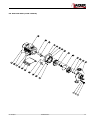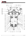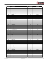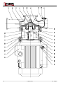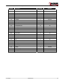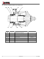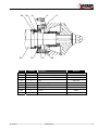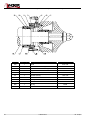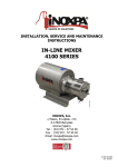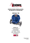
1
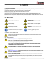
INSTALLATION, SERVICE AND
MAINTENANCE INSTRUCTIONS
DIN-FOOD
INOXPA, S.A.
c/Telers, 54 Aptdo. 174
E-17820 Banyoles
Girona (Spain)
Tel. : (34) 972 - 57 52 00
Fax. : (34) 972 - 57 55 02
Email: [email protected]
www.inoxpa.com
01,110,30,03EN
ED. 2008/07
EC DECLARATION OF CONFORMITY
(In accordance with Directive 98/37/EC, annex II, part A)
We, the manufacturer:
INOXPA, S.A.
c/ Telers, 54
17820 Banyoles (Girona) - Spain
Hereby declare that the products
CENTRIFUGAL PUMP
DIN-FOOD
Name
Type
2008
2008
Year of
Manufacture
are in conformity with the provisions of the Council Directives:
Machine Directive 98/37/EC and comply with the essential requirements of said
Directive and the harmonised standards:
UNE-EN
UNE-EN
UNE-EN
UNE-EN
UNE-EN
UNE-EN
ISO 12100-1/2:2003
1050:1996
809/A1/AC:2001
294/A1/AC:1993
953:1997
563/A1/AC:2000
Low-Voltage Directive 2006/95/CE (replacing Directive 73/23/CE) and conform to
UNE-EN 60204-1:1997 and UNE-EN 60034-1/A11:2002.
Electromagnetic Compatibility Directive 2004/108/CE (replacing Directive
89/336/CE) and conform to UNE-EN 60034-1/A11:2002.
In conformity with Regulation (CE) No. 1935/2004 on materials and objects intended to
come into contact with foodstuffs (repealing 89/109/EEC), in accordance with which the
materials in contact with the product do not transfer its constituents to the foodstuffs in
quantities large enough to put human health at risk.
Declaration of Incorporation (Directive 98/37/EC, annex II, part B):
The aforementioned equipment shall not be commissioned until the
machine in which they will be incorporated has been declared as being in
conformity with the Machine Directive.
Banyoles, July
july 2008
2008
1. Safety
1.1. INSTRUCTIONS MANUAL
This manual contains information about the receipt, installation, operation, assembly, disassembly and maintenance of the DINFOOD pump.
The information published in the instruction manual is based on updated information.
INOXPA reserves the right to modify this instruction manual without prior notice.
1.2. START-UP INSTRUCTIONS
This Instructions Manual contains essential and useful information for properly operating and maintaining your pump.
Read these instructions carefully before starting up the pump; become familiar with the operation and use of your pump and
follow the instructions closely. These instructions should be kept in a safe location near the installation.
1.3. SAFETY
1.3.1. Warning symbols
Danger for persons in general
Danger of injury caused by rotating
equipment parts
Electrical danger
Danger! Caustic or corrosive agents
Danger! Suspended loads
Danger to the correct operation of the
equipment
Commitment to safety at the workplace
Protective goggles requirement
1.4. GENERAL SAFETY INSTRUCTIONS
Read this Instructions Manual carefully before installing the pump and starting it up. Contact
INOXPA in case of doubt.
1.4.1. During installation
The Technical Specifications of Chapter 8 should always be observed.
Never start up the pump before it has been connected to the pipeline.
Do not start up the pump if the pump cover is not placed.
Check that the motor specifications meet the requirements, especially when working under
conditions that involve the risk of explosion.
During the installation, all the electric work should be carried out by authorised personnel.
1.4.2. During operation
The Technical Specifications of Chapter 8 should always be observed. Under no circumstances can the
limit values specified be exceeded.
NEVER touch the pump or the pipes during operation when the pump is being used to decant hot
fluids or when it is being cleaned.
The pump contains moving parts. Never place your fingers inside the pump while the pump is in
operation.
ED. 2008/07
1.Maintenance
3
NEVER operate the pump with the suction and delivery valves closed.
NEVER spray the electrical motor directly with water. The standard protection of the motor is
IP-55: Protection against dust and sprayed water.
1.4.3. During maintenance
The Technical Specifications of Chapter 8 should always be observed.
NEVER dismantle the pump before the pipes have been emptied. Remember that some of the fluid
will always remain in the pump housing (when no drainage is provided). Note that the pumped fluid
may be dangerous or very hot. Consult the regulations in effect in each country for these cases.
Do not leave parts loose on the floor.
ALWAYS disconnect the pump from the power supply before starting maintenance work. Remove the
fuses and disconnect the cables from the motor terminals.
All electrical work should be carried out by authorised personnel.
1.4.4. Compliance with the instructions
Any non-fulfilment of the instructions may result in a risk for the operators, the environment and the machine, and may result
in the loss of your right to claim damages.
This non-fulfilment may result in the following risks:
•
Failure of important functions of the machines/plant.
•
Failure of specific maintenance and repair procedures.
•
Possibility of electric, mechanical and chemical risks.
•
Will place the environment in danger due to the release of substances.
1.4.5. Guarantee
Any warranty provided shall immediately be cancelled and void ipso jure, and INOXPA shall be compensated for any product
liability claim from third parties, if:
•
the service and maintenance work was not carried out in accordance with the service instructions, or the repair work
has not been carried out by our personnel or it has been conducted without our written authorization;
•
our equipment has been changed without prior written authorization;
•
the parts or lubricants used are not original INOXPA parts and products;
•
the materials were used incorrectly or negligently, or not in accordance with these instructions and their intended use;
•
pump parts were damaged by excessive pressure owing to the lack of a safety valve.
The General Delivery Terms already provided also apply.
No change can be made to the equipment without prior discussion with the manufacturer. For your
safety, please use original spare parts and accessories.
The use of other parts will exempt the manufacturer from any liability.
The service terms can only be changed with prior written authorisation from INOXPA.
Please do not hesitate to contact us in case of doubts or more complete explanations are required on specific data
(adjustments, assembly, disassembly, etc.).
4
1.Maintenance
ED. 2008/07
2. Table of Contents
1.
Safety
1.1. Instructions manual......................................................................................................... 3
1.2. Start-up instructions ........................................................................................................ 3
1.3. Safety............................................................................................................................. 3
1.4. General safety instructions ............................................................................................... 3
2.
Table of Contents
3.
Información General
3.1. Description...................................................................................................................... 7
3.2. Operating principle .......................................................................................................... 7
3.3. Application ...................................................................................................................... 7
4.
Installation
4.1. Pump reception ............................................................................................................... 9
4.2. Transport and storage ..................................................................................................... 9
4.3. Location.........................................................................................................................10
4.4. Coupling ........................................................................................................................10
4.5. Pipes ................................................................................¡Error! Marcador no definido.
4.6. Pressurisation tank .........................................................................................................11
4.7. Electrical installation .......................................................................................................11
5.
Start-up
5.1. Start-up .........................................................................................................................13
6.
Operating Problems
7.
Maintenance
7.1. General information ........................................................................................................15
7.2. Torque...........................................................................................................................15
7.3. Lubrication .....................................................................................................................15
7.4. Storage..........................................................................................................................15
7.5. Cleaning ........................................................................................................................16
7.6. Disassembly / assembly of the pump ...............................................................................17
8.
Technical Specifications
8.1. Technical specifications...................................................................................................25
8.2. Weights .........................................................................................................................25
8.3. DIN-FOOD dimensions (bare shaft) .................................................................................26
8.4. DIN-FOOD dimensions (bare shaft, with baseplate) ..........................................................27
8.5. DIN-FOOD dimensions (close-coupled) ............................................................................28
8.6. DIN-FOOD dimensions (close-coupled, with shroud) .........................................................29
8.7. DIN-FOOD pump (bare shaft)..........................................................................................30
8.8. DIN-FOOD pump (close-coupled) ....................................................................................31
8.9. DIN-FOOD pump (bare shaft) cross-section. ....................................................................32
8.10. DIN-FOOD (bare shaft). Parts list ..................................................................................33
ED. 2008/07
2.Maintenance
5
8.11. DIN-FOOD pump (close-coupled) cross-section.............................................................. 34
8.12. DIN-FOOD (close-coupled ). Parts list ........................................................................... 35
8.13. DIN-FOOD flushed mechanical seal (bare shaft) ............................................................ 36
8.14. DIN-FOOD flushed mechanical seal (close-coupled, size 160 and 180 motors) ................. 37
8.15. DIN-FOOD flushed mechanical seal (close-coupled, size 200 motors) .............................. 38
8.16. DIN-FOOD double mechanical seal (bare shaft) ............................................................. 39
6
2.Maintenance
ED. 2008/07
3. Información General
3.1. DESCRIPTION
INOXPA DIN-FOOD series centrifugal pumps are manufactured with a cold-stamped thicknplate and volute body. The parts in
contact with the product are manufactures in AISI 316L stainless steel, internal finish is n Ra 0.8.
The DIN-FOOD centrifugal pump is built with a bare shaft or close-coupled construction with a shrouded motor, axial suction
and radial discharge, connections with DIN-11864-2-B PN-10 flanges. The impeller is of a half-open design with double
curvature and manufactured in a single piece. The mechanical seal is balanced and completely sanitary; the springs are
protected to prevent contact with the product. The material of the wear surfaces is silicon carbide and graphite, with EPDM
gaskets in the standard version.
The motor complies with IEC standards, IP-55 protection, F-class insulation. Three-phase power 220-240 / 380-420 V or 380420 / 660 V at 50 Hz, depending on power supply. On demand, motors suitable for operating in explosive environments can be
provided. Depending on the environmental conditions, the motors can be flameproof (EExd) or enhanced-safety (EExe) motors.
The DIN-FOOD series model was developed specifically to meet all hygienic requirements required by the food industry.
In terms of hygiene, reliability and durability, the entire range meets all the requirements imposed by the aforementioned
industries. Its design enables the highest level of interchangeability of parts.
This equipment is suitable for use in the food-processing industry.
3.2. OPERATING PRINCIPLE
Housed inside the casing, the impeller rotates in conjunction with the pump shaft and it is comprised of varying number of
blades, depending on the pump model.
With this arrangement, the impeller blades convey energy to the fluid in the form of kinetic energy and pressure energy.
This pump is not reversible by simple reversal of the direction of rotation. The direction of rotation is clockwise when the pump
is viewed from the rear side of the motor.
3.3. APPLICATION
As a general rule, standard version DIN-FOOD pumps are mainly used in the food-processing industries for transferring fluids.
Various impeller diameters and speeds of the hydraulic specifications are provided for each pump type. The characteristics
charts also show the required absorbed power and NPSH.
Head (m)
3.3.1. Range of application
Flow
ED. 2008/07
3.Maintenance
7
Head (m)
Flow
Each pump has performance limits. The pump was selected for certain pumping conditions at the
time the order was placed. INOXPA shall not be liable for any damage resulting from the
incompleteness of the information provided by the purchaser (nature of the fluid, rpm, etc.).
8
3.Maintenance
ED. 2008/07
4. Installation
4.1. PUMP RECEPTION
INOXPA cannot be held responsible for the damage sustained by the equipment during transport or
unpacking. Visually check that the packaging is not damaged.
The pump will be accompanied by the following documents:
•
Dispatch notes.
•
Pump Instructions and Service Manual.7
•
Motor Instructions and Service Manual (*)
(*) when the pump is supplied with a motor by INOXPA.
Unpack the pump and check the following:
• The pump suction and delivery connections, remove the
remains of any packaging materials.
• Check that the pump and the motor have not suffered any
damage.
• If the equipment is not in good condition and/or any part is
missing, the carrier should draw up a report accordingly as
soon as possible.
4.1.1. Pump identification
Serial number
Pump plate
4.2. TRANSPORT AND STORAGE
DIN-FOOD pumps are often too heavy to be handled and stored manually.
Lift the pump as shown below:
ED. 2008/07
4.Maintenance
9
4.3. LOCATION
Place the pump as close as possible to the suction tank, and if possible below the product level.
Place the pump so as to allow sufficient space around it to access the pump and the motor. (See Chapter 8 Technical
Specifications for dimensions and weight).
Set up the pump on a flat, level surface.
The foundation must be rigid, horizontal, flat and vibration-proof.
Install the pump so as to allow sufficient ventilation.
If the pump is installed outdoors, it should be protected by a roof. Its location should enable easy
access for any inspection or maintenance operations.
4.4. COUPLING
For the selection and fitting of couplings, please refer to the supplier’s manual. In some cases, the starting torque of positivedisplacement pumps can be quite high. Therefore, the chosen coupling should be 1.5 to 2 times the recommended torque.
Alignment
The shafts of the pump unit and the pump transmission are aligned correctly when assembled at our factory.
Check the alignment of the pump unit after installation.
Place a straight-edge ruler (A) on the coupling: the ruler must be in contact with both halves of the coupling over its entire
length. See illustration.
Repeat the check, this time on both sides of the coupling, close to the shaft. For the sake of accuracy, this check should also be
performed using an outside calliper (B) on two diametrically opposed points on the exterior surfaces of the two halves of the
coupling.
Maximum alignment deviations:
Exterior diameter
of the coupling
(mm)
70 - 80
81 - 95
96 - 110
111 - 130
131 - 140
141 - 160
161 - 180
181 - 200
201 - 225
10
Minimum Va.
[mm]
2
2
2
2
2
2
2
2
2
Maximum Va. Max. Va. - Min. Va.
[mm]
[mm]
4
4
4
4
4
6
6
6
6
4.Maintenance
0,13
0,15
0,18
0,21
0,24
0,27
0,3
0,34
0,38
Var.
[mm]
0,13
0,15
0,18
0,21
0,24
0,27
0,3
0,34
0,38
ED. 2008/07
4.5. PIPES
• As a general rule, the suction and delivery pipes should be fitted in straight sections, with the least possible number of
bends and fittings, in order to minimise pressure loss caused by friction.
• Ensure that pump inlet and outlet fittings are properly aligned with the piping and of a similar diameter to the pump
connections.
• Place the pump as close as possible to the suction tank, if possible below the fluid level, or even below the tank, to achieve
the maximum static suction head.
• Place tpipesupports as close as possible to the pump suction inlet and delivery outlet.
4.5.1. Shut-off valves
The pump can be isolated for maintenance purposes. Shut-off valves should be fitted to the pump suction and delivery
connections.
These valves should ALWAYS be open when the pump is operating.
4.6. PRESSURISATION TANK
For models with a double mechanical seal, a pressurisation tank must be installed.
ALWAYS install a pressurisation tank 1 to 2 meters above the pump shaft. See Figure 4.6.1.
1...2m
ALWAYS connect the cooling fluid inlet to the lower connection of the seal chamber. Therefore, the
outflow of the cooling liquid will be through the upper connection of the chamber. See Figure 4.6.1.
Mechanical
Seal
Cierre mecánico
Figure 4.6.1: Pressurisation tank installation diagram
For more information on the pressurisation tank (installation, operation, maintenance, etc.), see the manufacturer’s instructions
manual.
4.7. ELECTRICAL INSTALLATION
The connection of the electrical motors must be performed by qualified personnel.
Take all necessary measures to prevent damage to connections and cables.
The electrical equipment, terminals and components of the control systems may still contain electric
current when switched off. Contact with them may be dangerous for operators or cause irreversible
damage to the equipment.
Before opening the pump, make sure that the electrical circuit is switched off.
ED. 2008/07
4.Maintenance
11
•
•
Connect the motor following the manufacturer’s instructions.
Check the direction of rotation (see the label on the pump).
Start up the pump motor briefly. Make sure, by looking at
the pump from the rear, that the motor fan is rotating in a clockwise direction.
ALWAYS check the direction of rotation of motor with fluid inside de pump.
For models with a seal chamber, ALWAYS make sure that the chamber is full of liquid before
checking the rotation direction.
12
4.Maintenance
ED. 2008/07
5. Start-up
Before starting the pump, thoroughly read the instructions provided in Chapter 4. Installation.
5.1. START-UP
Read Chapter 8 Technical Specification thoroughly . INOXPA cannot be held responsible for the
incorrect use of the equipment.
NEVER touch the pump or the pipes when hot fluid is being pumped.
5.1.1. Checks before starting up the pump
• Fully open the shut-off valves on the suction and delivery pipes.
• Check the pump oil level. Fill with the necessary amount of oil so that the level is in the centre of the sight glass (If starting
up for the first time: pumps are delivered with oil in the box. However, it is important to always remember to conduct this
check).
• If the fluid does not flow into the pump, prime the pump with fluid to be pumped.
The pump must NEVER be run dry.
• Check that the motor direction of rotation is correct.
5.1.2. Checks when starting up the pump
• Check that the pump is not making any unusual noises.
• Check that the absolute inlet pressure is high enough to avoid cavitation in the pump. See the curve to determine the
minimum pressure required above steam pressure (NPSHr).
• Check the flow pressure.
• Check that there are no leaks through the sealed areas.
A shut-off valve on the suction pipe must not be used to regulate flow. Shut-off valves must be fully
open during operation.
Check the motor power consumption to avoid electric overload.
Reduce the flow and the power consumed
by the motor:
• Regulating the flow to the pump delivery.
• Decreasing motor speed.
ED. 2008/07
5.Maintenance
13
6. Operating Problems
The following table provides solutions to problems that might arise during pump operation. The pump is assumed to have been
properly installed and correctly selected for the application.
Please contact INOXPA if technical assistance is required.
Operating Problems
Probable causes
Motor overload
The pump does not provide enough flow or pressure
No pressure on the delivery side
Uneven delivery flow / pressure
Noise and vibration
The pump gets clogged
Overheated pump
Abnormal wear
The mechanical seal is leaking.
8, 9, 13, 14, 20, 21, 22, 23, 24.
1, 2, 4, 5, 7, 9, 10, 17, 19.
2, 3, 6, 18.
1, 2, 4, 5, 6, 9.
2, 4, 5, 6, 7, 8, 9, 10, 13, 14,15, 20, 21, 22, 23, 24.
9, 10, 13, 14, 15, 20, 21, 22, 24.
8, 9, 10, 13, 14, 15, 20, 21, 22, 23, 24.
4, 5, 10, 14, 15, 20, 24.
11, 12, 16.
Probable causes
Solutions
1
2
Wrong direction of rotation
NPSH is not high enough
3
4
5
6
7
Pump not drained
Cavitation
Air is sucked in by the pump.
Clogged suction tube
Delivery pressure too high
8
Flow too high
9
10
11
12
13
Fluid viscosity too high
Fluid temperature too high
Mechanical seal damaged or worn.
O-rings unsuitable for the fluid.
The impeller scrapes.
14
15
16
17
18
19
Taught tubes
Foreign particles in the fluid
The mechanical seal spring tension is too low
Pump speed too low
The cut-off valve on the suction side is closed
Delivery pressure too low
20
21
22
23
24
Bearings are worn.
Insufficient lubricating oil
Unsuitable lubricating oil
Misaligned coupling
Pump and/or motor not attached to the bedplate.
Reverse the direction of rotation.
Increase the available NPSH:
- Place the suction tank higher
- Place the pump lower
- Reduce steam pressure
- Increase the diameter of the suction pipe
- Shorten and simplify the suction pipe
Drain or fill
Increase suction pressure (see also 2)
Check the suction pipe and all its connections
Check the suction pipe and all its filters, if any
If necessary, reduce pressure losses, e.g. by increasing the
diameter of the tube
Decrease the flow:
- Reduce the flow by means of a diaphragm.
- Partially shut off the delivery valve.
- Trim impeller.
- Reduce speed.
Reduce the viscosity, e.g. by heating the fluid
Reduce the temperature by cooling the fluid.
Replace the seal
Fit suitable O-rings after checking with the supplier.
- Reduce temperature
- Reduce suction pressure
- Adjust impeller / cover clearance.
Connect the tubing to the pump avoiding taughtness.
Fit a filter to the suction tube
Adjust as indicated in this Manual
Increase speed.
Check and open
Increase pressure:
- Increase impeller diameter.
-Increase the pump speed.
Replace bearings; service the pump
Refill with lubricating oil
Use suitable lubricating oil
Align the coupling
Attach the pump and/or motor and check that the tubes are
connected without taughtness and align the coupling
If the problems persist, stop using the pump immediately. Contact the pump manufacturer or their
representative.
14
6.Maintenance
ED. 2008/07
7. Maintenance
7.1. GENERAL INFORMATION
Like any other machine, this pump requires maintenance. The instructions contained in this manual cover the identification and
replacement of spare parts. The instructions have been prepared for maintenance personnel and for those responsible for the
supply of spare parts.
Please read Chapter 8 Technical Specification.
All replaced material should be duly eliminated/recycled according to the directives in effect in the
area.
ALWAYS disconnect the pump from the power supply before undertaking maintenance work.
7.1.1. Checking the mechanical seal
Regularly check that there are no leaks in the shaft area. If there are leaks through the mechanical seal, replace it following the
instructions given in the Assembly and Dismantling section.
7.2. TIGHTENING TORQUE
Material
Torque value [N.m.]
M5
M6
M8
M10
M12
M14
M16
M18
M20
8.8
6
10
25
49
86
135
210
290
410
A2
5
9
21
42
74
112
160
210
300
7.3. LUBRICATION
The bearings are lubricated by means of an oil bath.
The pumps are supplied with oil.
• Check the oil level regularly, e.g. weekly or after every 150 hours of service.
• The first oil change should be conducted after 150 hours of service.
• Following this, the oil should be changed after every 2,500 hours of service or at least once a year under normal operating
conditions.
When the oil is changed. the oil box should be filled up to the level in the centre of the sight-glass.
Do not overfill the support with oil.
Leave the pump in the stop position for a while and then check the oil level; if necessary, add a little more oil.
Oil for ambient temperatures of 5 to 50°C: ISO VG 68.
PUMP TYPE
Support oil
capacity [l.]
125-100-250
125-100-315
125-100-400
150-125-250
150-125-315
150-125-400
200-150-250
1,75
200-150-315
200-150-400
2
7.4. STORAGE
The pump must be completely emptied of fluid before storage. If possible, avoid exposing the components of the pump to
excessively damp environments.
ED. 2008/07
7.Maintenance
15
7.5. CLEANING
The use of aggressive cleaning products such as caustic soda and nitric acid may cause burns to the
skin.
Use rubber gloves during the cleaning process.
Always use protective goggles.
7.5.1. CIP process
If the pump is installed in a system with a CIP process, it is not necessary to dismantle the pump.
If there is no automatic cleaning process, dismantle the pump as indicated in the Assembly and Dismantling section.
Cleaning solutions for CIP processes.
Only use clear water (chlorine-free) to mix with the cleaning agents:
a) Alkaline solution:
1% by weight of caustic soda (NaOH) at 70ºC (150ºF)
1 Kg NaOH + 100 l. of water = cleaning solution
o
2.2 l. NaOH at 33% + 100 l. of water = cleaning solution
b) Acid solution:
0.5% by weight of nitric acid (HNO3) at 70ºC (150ºF)
0.7 litres HNO3 at 53% + 100 l. of water = cleaning
Check the concentration of the cleaning solutions to avoid damaging the pump seals.
To remove any remains of cleaning products, ALWAYS perform a final rinse with clean water on completion of the cleaning
process.
7.5.2. Automatic SIP
The steam sterilisation process is applied to all equipment including the pump.
DO NOT operate the equipment during the steam sterilisation process.
The parts/materials will not suffer damage provided the instructions set out in this manual are
followed.
Cold liquid cannot be introduced until the pump temperature is below 60oC (140oF).
The pump generates a substantial pressure loss through the sterilisation process; we recommend the
use of a bypass circuit provided with a discharge valve to ensure that the steam / overheated water
sterilises the entire circuit.
Maximum conditions during the steam or overheated water SIP process
a)
b)
c)
d)
16
Max. temperature:
140°C / 284°F
Max. time:
30 min.
Cooling:
Sterilised air or inert gas
Materials:
EPDM / PTFE (recommended)
FPM / NBR (not recommended)
7.Maintenance
ED. 2008/07
7.6. DISASSEMBLY / ASSEMBLY OF THE PUMP
7.6.1. Pump and impeller body
Disassembly
Remove the hexagonal screws (52) and washers (53) fixing the housing (01) to the lantern (04). Remove the blind nut (45)
and O-ring (80D), then take out the impeller (02).
Assembly
Slide the impeller (02) over the shaft (05) until making contact with the spacer (17), attach the O-ring (80D) in the slot of the
blind nut (45) and tighten the nut (45). Attach the housing (01) and fix it to the lantern (04) with hexagonal screws (52) and
washers (53).
ED. 2008/07
7.Maintenance
17
7.6.2. Single mechanical seal
Disassembly
Remove the rotary part of the mechanical seal (08).
Remove the screws (52E) fixing the cover (03) with the lantern (04).
Remove the pump cover (03), the fixed part of the mechanical seal (08A) will remain housed inside the cap.
Remove the fixed part of the mechanical seal (08).
Assembly
Check the location of the shaft (05) in relation to the pump cover (03). See section 7.6.7. Adjusting the pump shaft.
Attach the pump cover (03) to the lantern (04) and fasten with the screws (52E).
Place the fixed part of the mechanical seal in the cover housing (03) taking the knob into account.
Check that assembly measure used is that which is described below:
Slide the rotating part of the mechanical seal (08) over the shaft (05) till the
end.
18
ØD
A
51
34,5
58
37,5
CAUTION! When placing the new seal, assemble the parts and seals using
soapy water to ensure that they slide over each other, including the
stationary part and the rotary part of the shaft.
7.Maintenance
ED. 2008/07
7.6.3. Flushed mechanical seal (bare shaft)
Disassembly
Remove the rotary part of the mechanical seal (08).
Remove the screws (52E) fixing the cover (03) with the lantern (04).
Remove the pump cover (03) with the cap (10) and seal ring (30) still mounted. The fixed parts of the mechanical seals (08)
and (08B) remain housed in the group.
Remove the fixed part of the mechanical seal (08).
Remove the screws (52C) and detach the seal ring (30), the fixed part of the external mechanical seal (08B), the cap (10), and
the O-ring (80B).
Loosen the pins (55A) and extract the rotary part of the external mechanical seal (08A) with the sleeve (13).
Assembly
Check the location of the shaft (05) in relation to the pump cover (03). See section 7.6.7. Adjusting the pump shaft.
Attach the rotary part of the external mechanical seal (08A) with the gasket and spring on the sleeve (13) and fix the shaft
using the pins (55A).
Place the O-ring (80B) over the pump cover alignment (03).
Place the cap (10), the fixed part of the external mechanical seal (08B), and the seal ring (30), and fasten it all onto the pump
cover (03) using the screws (52C).
Carefully attach the entire assembly to the lantern (04) and fasten with the screws (52E). At the same time, both working
surfaces of the external mechanical seal (08A, 08B) will make contact with each other.
In order to fit the internal mechanical seal, see the section on assembling the simple mechanical seal.
CAUTION! When placing the new seal, assemble the parts and seals using
soapy water to ensure that these slide over each other, including the
stationary part and the rotary part of the shaft.
ED. 2008/07
7.Maintenance
19
7.6.4. Flushed mechanical seal (close-coupled, size 160 and 180 motors)
Disassembly
Remove the rotary part of the mechanical seal (08).
Remove the screws (52E) fixing the cover (03) with the lantern (04).
Remove the pump cover (03) with the cap (10) and seal ring (30) still mounted. The fixed parts of the mechanical seals (08)
and (08B) remain housed in the group.
Remove the fixed part of the mechanical seal (08).
Remove the screws (52C) and detach the seal ring (30), the fixed part of the external mechanical seal (08B), the cap (10), and
the O-ring (80B).
Remove the pins (55A) and extract the rotary part of the external mechanical seal (08A) with the gasket and spring.
Assembly
Check the location of the shaft (05A) in relation to the pump cover (03). See section 7.6.7. Adjusting the pump shaft.
Attach the rotary part of the external mechanical seal (08A) with the gasket and spring on the shaft (05A) and fasten using the
pins (55A).
Place the O-ring (80B) over the pump cover alignment (03).
Place the cap (10), the fixed part of the external mechanical seal (08B), and the seal ring (30), and fasten it all onto the pump
cover (03) using the screws (52C).
Carefully attach the entire assembly to the lantern (04) and fasten with the screws (52E). At the same time, both working
surfaces of the external mechanical seal (08A, 08B) will make contact with each other.
In order to fit the internal mechanical seal, see the section on assembling the simple mechanical seal.
-{}-
CAUTION! When placing the new seal, assemble the parts and seals using
soapy water to ensure that these slide over each other, including the
stationary part and the rotary part of the shaft.
20
7.Maintenance
ED. 2008/07
7.6.5. Flushed mechanical seal (close-coupled, size 200 motors)
Disassembly
Remove the rotary part of the mechanical seal (08).
Remove the screws (52E) fixing the cover (03) with the lantern (04).
Remove the pump cover (03) with the cap (10), back-cover (10A), and seal ring (30) still mounted. The fixed parts of the
mechanical seals (08) and (08B) remain housed in the group.
Remove the fixed part of the mechanical seal (08).
Remove the screws (52C) and detach the seal ring (30), the fixed part of the external mechanical seal (08B), the cap (10), and
the O-ring (80B).
Remove the screws (51) and detach the back-cover (10A) and the O-ring (80B).
Loosen the pins (55A) and extract the rotary part of the external mechanical seal (08A) with the sleeve (13).
Assembly
Check the location of the shaft (05A) in relation to the pump cover (03). See section 7.6.7. Adjusting the pump shaft.
Attach the sleeve (13) until making contact with the shaft (05A).
Attach the rotary part of the external mechanical seal (08A) with the gasket and spring on the sleeve (13) and fix the shaft
using the pins (55A).
Attach the O-ring (80B) with the back-cover (10A) on the pump cover alignment (03) and fasten the screws (51).
Place the O-ring (80B) on the cap alignment (10) and attach the fixed part of the external mechanical seal (08B), the seal ring
(30), and fasten it all onto the back-cover (10ª) using the screw (52C).
Carefully attach the entire assembly to the lantern (04) and fasten with the screws (52E). At the same time, both working
surfaces of the external mechanical seal (08A, 08B) will make contact with each other.
In order to fit the internal mechanical seal, see the section on assembling the simple mechanical seal.
CAUTION! When placing the new seal, assemble the parts and seals using
soapy water to ensure that these slide over each other, including the
stationary part and the rotary part of the shaft.
ED. 2008/07
7.Maintenance
21
7.6.6. Double mechanical seal (bare shaft)
Disassembly
Remove the spacer (17) together with the O-rings (80D).
Remove the screws (52C) leaving the external cover loose (10B) with the fixed part of the external mechanical seal (08A) and
the O-ring (80B).
Remove the screws (52E) fixing the pump cover (03A) with the lantern (04).
Remove the pump cover (03A) with the double seal cap (10A) and the internal cover (10C) still mounted. The fixed part of the
internal mechanical seal (08) remains housed in the assembly.
Remove the screws (52D) and detach the double seal cap (10A) with the O-ring (80B).
Remove the internal cover (10C) with the O-ring (80C) and the fixed part of the internal mechanical seal (08).
Loosen the pins of the rotary parts of the mechanical seals (08) and (08A), and remove them from the shaft (05A).
Remove the external cover (10B) with the fixed part of the external mechanical seal (08A) and the O-ring (80B).
Assembly
Check the location of the shaft (05A) in relation to the pump cover (03A). See section 7.6.7. Adjusting the pump shaft.
Place the fixed part of the external mechanical seal (08A) in the housing of the external cover (10B), taking the pivot into
account, and place the O-ring (80B) over the cover alignment.
Attach the whole assembly and leave it loose at the end of the shaft (05A).
Slide the rotary part of the external mechanical seal (08A) onto the shaft (05A). Fasten it according to dimension A in the table.
Attach the rotary part of the internal mechanical seal (08) as far as the rotary part of the external mechanical seal and fasten
it.
Place the fixed part of the internal mechanical seal (08) in the housing of the internal cover (10C), taking the pivot into
account, and place the O-ring (80B) in the cover groove.
Attach the whole assembly to the pump cover housing (03A) and align the fixing bores.
Attach the O-ring (80B) with the double seal cap (10A) on the internal cover alignment (10C) and fasten the screws (52D).
Carefully attach the entire assembly to the lantern (04) and fasten with the screws (52E). At the same time, both working
surfaces of the internal mechanical seal (08) will make contact with each other.
Carefully place the external cover (10B) with the fixed part of the external mechanical seal (08A) and the O-ring (80B) on the
double seal cap alignment (10A) and fasten with the screws (52C). At the same time, both working surfaces of the external
mechanical seal (08A) will make contact with each other.
22
7.Maintenance
Seal
diameter
53
62,5
60
68
A
ED. 2008/07
CAUTION! When placing the new seal, assemble the parts and seals using
soapy water to ensure that these slide over each other, including the
stationary part and the rotary part of the shaft.
7.6.7. Adjusting the pump shaft
Check that the shaft (05) assembly dimension in relation to the pump cover (03) is as indicated below:
Pump type
ØD
A
250
51
16
315/400
51
8
315/400
58
20
If not, adjust the dimension until it is as indicated below.
• For close-coupled type models, loosen the setbolts (55) and slide the shaft (05) until the dimension has been adjusted.
Finally, firmly tighten the setbolts.
• For bare shaft type models, loosen the hexagonal screws (52A) and nuts (54), and adjust the dimension using the pins (55).
Once adjusted, tighten the nuts (54) and screws (52A).
7.6.8. Lantern and motor (close-coupled)
Disassembly
Remove the hexagonal screws (52A), nuts (54), and washers (53) and (53A), to be able to take out the lantern (04).
Loosen the setbolts (55) and take out the shaft (05).
Remove the screws (52B), nuts (54A), and washers (53B). This will make it possible to remove the motor (93 from the
baseplate (38).
Assembly
Place the motor (93) onto the baseplate (38) and attach with screws (52B), nuts (54A), and washers (53B).
Slide the shaft (05) over the shaft of the motor (93) until coming to a stop, and fasten with the setbolts (55).
Place the lantern (04) in its assembly position and fix it to the motor (93) with hexagonal screws (52A), nuts (54), and washers
(53) and (53A).
ED. 2008/07
7.Maintenance
23
24
7.Maintenance
ED. 2008/07
8. Technical Specifications
8.1. TECHNICAL SPECIFICATIONS
50Hz
-1
60Hz
3
Maximum flow (1450 min ).....................................................
Maximum differential pressure ................................................
Maximum suction pressure ......................................................
Maximum working pressure ....................................................
Operating temperature ...........................................................
1000 m /h
6 bar (87 PSI)
14 bar (203 PSI)
20 bar (290 PSI)
-10ºC to +140ºC (EPDM)
14ºF to 284ºF (EPDM)
1450 min-1
DIN 11864-2 (standard)
Maximum speed ....................................................................
Suction / delivery connections ........................................…..
1000 m3/h
9 bar (131 PSI)
11 bar (160 PSI)
20 bar (290 PSI)
-10ºC to +140ºC (EPDM)
14ºF to 284ºF (EPDM)
1750 min-1
DIN 11864-2 (standard)
Use special protection when the noise level in the operation area exceeds 85 dB(A).
Materials
Parts in contact with product........................................
Other parts in stainless steel. .......................................
Gaskets in contact with product ...................................
Other materials for optional gaskets ......................................
Surface finish ......................................................................
Mechanical seal
Type of seal ..........................................................................
Flushed mechanical seal
Maximum pressure..................................................................
Flow rate................................................................................
Double mechanical seal
Operating pressure .................................................................
Mechanical seal
materials
AISI 316L
AISI 304
EPDM (standard)
Check with the supplier
Standard polishing
Single internal seal
1 bar (14.5 PSI)
6-10 l/min
1.5~2 bar (22~29 PSI) above the
operating pressure of the pump
Type of mechanical seal
Flushed
Double (atmosphere side)
Graphite
Silicon carbide
Single internal
Stationary part
Rotary part
Double (product side)
Silicon carbide
8.2. WEIGHTS
Pump type
- Bare shaft -
Weight
Weight
Pump type –
[Kg]
[lbs]
close-coupled
125-100-250
113
249
125-100-315
127
280
125-100-400
135
298
150-125-250
118
260
150-125-315
133
293
150-125-400
149
329
200-150-250
124
273
200-150-315
194
428
200-150-400
210
463
ED. 2008/07
125-100-250
150-125-250
200-150-250
8.Maintenance
Weight
Weight
[Kg]
[lbs]
160
204
449
180
239
526
160
210
462
180
256
563
180
263
579
200
360
792
MOTOR
25
8.3. DIN-FOOD DIMENSIONS (BARE SHAFT)
Flange dimensions DIN 11864-2-A
DN
D
k
d4
100
159
137
117
125
183
161
142
150
213
188
168
200
263
238
218
d2
8 x ∅11
8 x ∅14
-{}-
PUMP TYPE
DNa
DNi
d
l
125-100-250
125-100-315
125
100
42
110
a
121
125-100-400
130
150-125-250
128
150-125-315
150
125
42
110
150-125-400
140
200-150-250
200-150-315
200-150-400
26
137
42
200
150
48
142
110
153
f
h1
h2
522
250
316
280
352
330
402
250
355
280
372
330
422
537
250
375
670
280
402
667
330
452
510
530
518
8.Maintenance
b
m1
m2
90
160
120
100
200
90
100
90
100
n1
n2
440
350
490
400
150
550
450
23
160
120
440
350
18
200
150
490
400
550
450
440
350
490
400
550
450
200
150
n3
110
110
s1
18
23
110
140
s2
363
14
350
370
14
14
23
w
18
358
378
500
498
ED. 2008/07
8.4. DIN-FOOD DIMENSIONS (BARE SHAFT, WITH BASEPLATE)
PUMP TYPE
125-100-250
150-125-250
200-150-250
125-100-315
150-125-315
200-150-315
125-100-400
150-125-400
200-150-400
ED. 2008/07
MOTOR
160
160
180
160
160
180
180
160
180
180
200
160
160
180
180
200
160
180
180
200
225
160
180
200
225
250
280
200
225
250
280
225
250
280
280
315
225
250
280
280
315
315
315
M
L
M
M
L
M
L
L
M
L
L
M
L
M
L
L
L
M
L
L
L
M
L
DNa
125
150
200
125
150
200
DNi
100
125
150
100
125
150
a
121
128
142
121
137
153
M
S
L
M
S
M
S
M
S
M
S
M
S
M
L
125
150
200
100
125
150
130
140
153
f
1250
1290
1330
1265
1305
1345
1365
1330
1365
1385
1405
1240
1280
1315
1335
1355
1305
1340
1360
1380
1490
1470
1510
1550
1660
1725
1820
1365
1475
1540
1705
1495
1560
1725
1785
1790
1655
1720
1885
1945
1950
2090
2120
h1
h2
b
316
35
l
550
m1
m2
m3
n1
n2
1300
1020
620
565
1350
990
s
w
1335
565
550
355
40
1340
565
340
140
550
375
35
565
620
1335
580
352
35
595
1385
650
580
372
30
370
45
595
650
670
580
595
650
180
1380
23
1395
720
1545
1500
1140
1735
1700
1300
1370
1350
990
1520
1710
1380
1530
1500
1700
1350
1500
1140
1300
990
1140
870
1720
1700
1300
935
1820
1800
1400
720
1545
1500
1140
665
670
402
35
20
420
820
700
720
10
870
30
720
422
20
430
45
420
452
870
1735
1700
1300
935
1835
1800
1400
200
180
200
180
200
820
765
720
665
820
765
180
35
430
8.Maintenance
200
27
8.5. DIN-FOOD DIMENSIONS (CLOSE-COUPLED)
Flnge dimensions DIN 11864-2-A
DN
D
k
d4
100
159
137
117
125
183
161
142
150
213
188
168
200
263
238
218
PUMP TYPE
125-100-250
MOTOR DNa DNi
160
a
125 100 121
180
150-125-250
160
180
200
28
8 x ∅11
8 x ∅14
f
h1
850
h2
b
c
c1
150 125 128
865
l
475
250
90
68
355
965
1005 340
m1
m2
n1
n2
n3
n4
s1
s2
160 120
367
18
440 350 415 470
18
200
68
88
400 305 585 210
8.Maintenance
349
374
475
375
w
342
360 260 460
945
200 150 142
c2
460
316
930
180
200-150-250
d2
150
381
23
600 545 545 600
23
384
ED. 2008/07
8.6. DIN-FOOD DIMENSIONS (SHROUDED, CLOSE-COUPLED)
Flange
dimensions DIN 11864-2-A
DN
D
k
d4
100
159
137
117
125
183
161
142
150
213
188
168
200
263
238
218
125-100-250
160
125 100 121
d2
8 x ∅11
8 x ∅14
960
344
316
180
150-125-250
160
160 120
250
150 125 128
975
90
68
360 260 525
369
18
440 350 415 470
18
355
180
200-150-250
180
200
ED. 2008/07
351
376
200 150 142
995
1105 340
200
375
68
88
400 305 690 210
8.Maintenance
150
383
23
600 545 545 600
23
386
29
8.7. DIN-FOOD PUMP (BARE SHAFT)
54
55
12
88A
80
62
63
70
66
52A
85
80B
06
86
61A
05
61
70A
87
18
88
12A
51A
52
53
04
51
03
08
80A
52B
53A
02
07
80D
45
50A
47A
01
52E
91B
91
91A
30
8.Maintenance
ED. 2008/07
8.8. DIN-FOOD PUMP (CLOSE-COUPLED)
91B
91
91A
ED. 2008/07
8.Maintenance
31
8.9. DIN-FOOD PUMP (BARE SHAFT). CROSS-SECTION.
32
8.Maintenance
ED. 2008/07
8.10. DIN-FOOD (BARE SHAFT). PARTS LIST
Position
Description
Quantity
Material
01
Pump casing
1
AISI 316L
02
Impeller
1
AISI 316L
03
Pump cover
1
AISI 316L
04
Lantern
1
GG-15
05
Shaft
1
AISI 316L
06
Bearings support
1
GG-15
07
Rear leg
1
GG-15
08
Mechanical seal
1
-
12
Rear bearings cover
1
F-114
12A
Front bearings cover
1
F-114
18
Front cover gasket
1
Gasket cardboard
45
Cap nut
1
AISI 316L
47
Lantern protector
2
AISI 304
Screw
4
A2
51
Allen screw
6
8.8
51A
Allen screw
4
8.8
50A
52
Hexagonal screw
12
A2
52A
Hexagonal screw
6
8.8
52B
Hexagonal screw
2
A2
52E
Hexagonal screw
2
A2
53
Grower washer
12
A2
53A
Grower washer
2
A2
54
Hexagonal nut
3
8.8
55
Pin
3
8.8
61
Key
1
A2
61A
Key
1
F-114
Self-locking nut
1
Steel
63
Safety washer
1
Steel
66
Elastic ring
1
Steel
70
Angular double-contact bearings
1
Steel
Cylindrical roller bearings
1
Steel
80
O-ring
1
EPDM
80ª
O-ring
1
EPDM
80B
O-ring
1
NBR
80D
O-ring
1
EPDM
82
Splash ring
1
EPDM
85
Oil plug
1
AISI 303
86
Sight-glass
1
Plastic
87
Drain plug
1
Plastic
88
Lock
1
NBR
88A
Lock
1
NBR
91
Flange
1
AISI 304
91A
Bushing
1
AISI 316L
91B
O-ring
1
EPDM
62
70A
ED. 2008/07
8.Maintenance
33
8.11. DIN-FOOD PUMP (CLOSE-COUPLED). CROSS-SECTION
34
8.Maintenance
ED. 2008/07
8.12. DIN-FOOD (CLOSE-COUPLED). PARTS LIST
Position
Description
Quantity
Material
01
Casing
1
AISI 316L
02
Impeller
1
AISI 316L
03
Pump cover
1
AISI 316L
04
Lantern
1
GG-15
05
Shaft
1
AISI 316L
08
Mechanical seal
1
-
38
Bedplate
1
AISI 304
45
Cap nut
1
AISI 316L
47A
Lantern protector
2
AISI 304
50A
Screw
8
A2
52
Hexagonal screw
8
A2
52A
Hexagonal screw
4
A2
52B
Hexagonal screw
4
A2
52E
Hexagonal screw
2
A2
53
Grower washer
12
A2
Flat washer
4
A2
53A
53B
Flat washer
4
A2
54
Hexagonal nut
4
A2
54A
Hexagonal nut
4
A2
55
Pin
2
A2
61
Key
1
A2
80A
O-ring
1
EPDM
80D
O-ring
1
EPDM
82
Splash ring
1
EPDM
91
Flange
1
AISI 304
91A
cec bushing
1
AISI 316L
91B
O-ring
1
EPDM
93
Motor
1
-
ED. 2008/07
8.Maintenance
35
8.13. DIN-FOOD. FLUSHED MECHANICAL SEAL (BARE SHAFT)
36
Position
Quantity
Description
Material
08A
1
Mechanical seal - rotary part -
-
08B
1
Mechanical seal - stationary part
-
10
1
Cap
AISI 316L
13
1
Cooled seal sleeve
AISI 316L
30
1
Cooled seal ring
AISI 316L
52C
4
Hexagonal screw
A2
55A
3
Pin
A2
80B
1
O-ring
92
2
Connection elbow
EPDM
8.Maintenance
AISI 316
ED. 2008/07
8.14. DIN-FOOD. FLUSHED MECHANICAL SEAL (CLOSE-COUPLED, SIZE 160 AND 180 MOTORS)
Position
ED. 2008/07
Quantity
Description
Material
AISI 316L
05A
1
Shaft
08A
1
Mechanical seal - rotary part -
-
08B
1
Mechanical seal – stationary part
-
10
1
Cap
AISI 316L
30
1
Cooled seal ring
AISI 316L
52C
4
Hexagonal screw
A2
55A
3
Pin
A2
80B
1
O-ring
92
2
Connection elbow
EPDM
8.Maintenance
AISI 316
37
8.15. DIN-FOOD. FLUSHED MECHANICAL SEAL (CLOSE-COUPLED, SIZE 200 MOTORS)
Position
38
Quantity
Description
Material
AISI 316L
05A
1
Shaft
08A
1
Mechanical seal - rotary part -
-
08B
1
Mechanical seal – stationary part
-
10
1
Cap
AISI 316L
13
1
Cooled seal sleeve
AISI 316L
30
1
Cooled seal ring
AISI 316L
51
2
Allen screw
A2
52C
4
Hexagonal screw
A2
55A
3
Pin
A2
80B
1
O-ring
92
2
Connection elbow
EPDM
8.Maintenance
AISI 316
ED. 2008/07
8.16. DIN-FOOD DOUBLE MECHANICAL SEAL (BARE SHAFT)
ED. 2008/07
Position
Quantity
Description
Material
03A
1
Pump cover
AISI 316L
05A
1
Shaft
AISI 316L
08
1
Internal mechanical seal
-
08A
1
External mechanical seal
-
10A
1
Double seal cap
AISI 316L
10B
1
External cover
AISI 316L
10C
1
Internal cover
AISI 316L
17
1
Spacer
AISI 316L
52C
4
Hexagonal screw
A2
52D
4
Hexagonal screw
A2
80B
2
O-ring
EPDM
80C
1
O-ring
EPDM
80D
2
O-ring
EPDM
92
2
Connection elbow
8.Maintenance
AISI 316
39
INOXPA, S.A.
c/ Telers, 57 – PO Box 174
Tel: +34 972 575 200
Fax: +34 972 575 502
17820 BANYOLES – GIRONA
SPAIN
www.inoxpa.com
e-mail: [email protected]
BARCELONA – FLUAL, S.L.
Tel: 937 297 280
e-mail: [email protected]
MADRID – INOXFLUID, S.L
Tel: 918 716 084
e-mail: [email protected]
BILBAO – STA, S.L.
Tel: 944 572 058
e-mail: [email protected]
VALENCIA – INOXDIN, S.L.
Tel: 963 170 101
e-mail: [email protected]
VALLADOLID – ALTAFLUID, S.L.
Tel: 983 403 197
e-mail: [email protected]
CÁDIZ – CORFLUID, S.L.
Tel: 956 140 193
e-mail: [email protected]
ZARAGOZA – FLUAL, S.L.
Tel: 976 591 942
e-mail: [email protected]
LA RIOJA – STA, S.L.
Tel: 941 228 622
e-mail: [email protected]
SEVILLA – CORFLUID, S.L.
Tel: 954 296 852
e-mail: [email protected]
CÓRDOBA – CORFLUID, S.L.
Tel: 957 169 145
e-mail: [email protected]
LA MANCHA – INOXFLUID, S.L.
Tel: 926 514 190
e-mail: [email protected]
ASTURIAS – STA, S.L.
Tel: 985 267 553
e-mail: [email protected]
INOXPA FRANCE, S.A. - AGENCE NORD
2, Avenue Saint Pierre
59118 WAMBRECHIES (France)
Tél: 33(0)320 631000
Fax: 33(0)320 631001
e-mail: [email protected]
AGENCE LYON Z.A.C. D’EPINAY
69 Allée des Caillotières
GLEIZE 69400 (France)
Tél: 33(0)474 627100
Fax: 33(0)474 627101
e-mail: [email protected]
AGENCE SUD
Route d’Olonzac
11200 HOMPS (France)
Tél: 33(0)468 278680
Fax: 33(0)468 278681
e-mail: [email protected]
AGENCE OUEST
ZA des Roitelières
44330 LE PALLET (France)
Tél: 33(0)228 010172
Fax: 33(0)228 010173
e-mail: [email protected]
INOXPA SOLUTIONS FRANCE
Rue Henri Becquerel
F - 60230 CHAMBLY (France)
Tél: 33(0)130289100
Fax: 33(0)130289101
e-mail: [email protected]
INOXPA ITALIA S.R.L.
Via Olivetti, s.n.c., Z.I.
26010 VAIANO CREMASCO - Cr - (Italia)
Tel: 39(0)373 791076
Fax: 39(0)373 791113
e-mail: [email protected]
INOXPA SWEDEN
Laxfiskevägen 12
SE-43338 PARTILLE (Sweden)
Tel: 46 (0) 31 336 05 60
Fax: 46 (0 )31 336 05 61
e-mail: [email protected]
INOXPA SKANDINAVIEN A/S
H∅egh Guldbergsgade 27
HORSENS DK-8700 (Denmark)
Tel: (45) 76 28 69 00
Fax: (45) 76 28 69 09
e-mail: [email protected]
S.T.A. PORTUGUESA LDA.
Zona Industrial - Lugar do Guardal
ALGERIZ. 3730-266 VALE DE CAMBRA
(Portugal)
Tel: 351 256 472722
Fax: 351 256 425697
e-mail: [email protected]
INOXPA POLAND sp z o.o.
Ul. Arkonska, 54
80-392 Gdansk (Poland)
Tel. 48 58 511 00 05
Fax: 48 58 556 72 51
e-mail: [email protected]
INOXPA SOUTH AFRICA (PTY) LTD
HEAD OFFICE (PTY) Ltd.
Unit 4 Production Park, Epsom Ave
NORTHLANDS – NORTHRIDING
JOHANNESBURG – SOUTH AFRICA
PO Box 1464, Olivedale, 2158
Tel: 011-796-5170
Fax: 086-680-7756
e-mail: [email protected]
INOXPA DEUTSCHLAND GMBH
Kohlhammerstrasse, 6
D - 70771 LEINFELDEN
DEUTSCHLAND
Tel: 49 (0) 711 758 59 73
Fax: 49 (0) 711 758 59 750
e-mail: [email protected]
INOXPA USA, Inc
3715 Santa Rosa Avenue Suite A4
Santa Rosa, CA95407
(California)
Tel: 1 707 585 3900
Fax: 1 707 585 3908
e-mail: [email protected]
INOXPA REALM Ltd.
15, Omrside Way – Holmethorpe State
REDHILL – SURREY RH1 2QA
Tel: 44 2086895521
Fax: 44 2086890245
e-mail: [email protected]
BOMBAS IMCHISA, S.A
Calle dos, nº 9447
QUILICURA – SANTIAGO de CHILE
Tel: 56-2-7266945/6
e-mail: [email protected]
INOXRUS Ltd.
Промзона Парнас, ул.Верхняя 4
194292 Санкт-Петербург
Россия
Тел.: 7 812 622 16 26
Fax: 7 812 622 19 26
e-mail: [email protected]
INOXRUS Ltd.
ОСК Мидланд, офис 11
Химкинский район, квартал Клязьма
141400 Москва
Тел.: 495 223 04 11
e-mail: [email protected]
In addition to our branch offices, INOXPA operates with an independent distributor network which encompasses a total of more than 50
countries throughout the world. For more information consult our web page:
www.inoxpa.com